firelock nxt™ actuated valve with preaction trim 30.82
TRANSCRIPT
VNIIPO
FEATURES The valve allows the water to operate a water motor alarm and/or electric pressure alarms, which continue until the flow of water stops.
The valve is rated to 300 psi/2065 kPa water working pressure and is factory tested hydrostatically to 600 psi/4135 kPa for sizes 1 1/2 – 8"/40 – 200 mm. Required air pressure is 13 psi/90 kPa. The Series 769 is available grooved x grooved. Standard grooved dimensions conform to ANSI/AWWA C606.
Victaulic Series 769 Preaction valves do NOT require a separate check valve in the preaction system and feature a straight-through valve body design that provides superior flow and low-pressure drop. The valve body is tapped with a special drain for a complete system. The valve has simple access to all internal parts for easy maintenance. All internal parts are replaceable.
Maintenance and service can be performed from the installed position. The rubber clapper seal is replaced easily without removing the clapper from the valve. The body is tapped for main drain and all available trim configurations. The valve is painted inside and out to increase corrosion resistance.
The Victaulic FireLock NXT Series 769 Preaction valve trim includes an alarm test valve, which allows testing of the alarm system without reducing the system pressure. The Series 769 Preaction Valve must be located in an area maintained above 40°F (4°C), which is not subject to weather, freezing temperatures, or physical damage.
NOTE: The bare value carries the LPCB and VdS approvals for deluge applications only. There is no LPCB or VdS recognition of the preaction configurations.
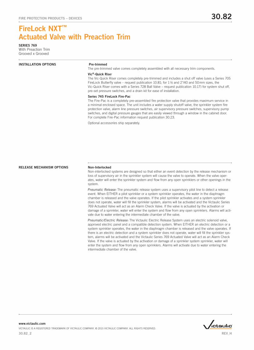
ClapperSeal
DiaphragmAssembly
LatchClapper
Seat
NOTE: VALVE IS SHOWN ABOVE IN THE “SET” POSITION
Exaggerated for Clarity
The patented Victaulic FireLock NXT Series 769 Preaction Valve controls the water supply entry into the Preaction system piping and sprinklers. The Preaction System is normally super-vised with pressurized air or nitrogen in order to detect any leaks in the system. The Series 769 is a low differential, latched clapper valve that uses a unique direct acting diaphragm to separate system water supplies from Preaction pipe sprinkler systems. The positive latching mechanism uses the supply water pressure from upstream (city side) of the main control valve to hold the clapper shut. When the water pressure in the diaphragm chamber is released the latch retracts from the clapper and the valve actuates. The low differential and unique latch and actuator design of the valve allows the valve to be self-resetting; therefore it is not neces-sary to remove the cover. The low differential design is not subject to water columns.
Exaggerated for Clarity
NOTE: Valve is shown in the “set” position
30.82_1
FireLock NXT™ Actuated Valve with Preaction TrimSERIES 769With Preaction TrimGrooved x Grooved
30.82FIRE PROTECTION PRODUCTS – DEVICES
JOB/OWNER CONTRACTOR ENGINEER
System No. __________________________ Submitted By ________________________ Spec Sect ____________ Para __________
Location ____________________________ Date ________________________________ Approved ___________________________
Date ________________________________
www.victaulic.comVICTAULIC IS A REGISTERED TRADEMARK OF VICTAULIC COMPANY. © 2015 VICTAULIC COMPANY. ALL RIGHTS RESERVED.
REV_H
MEA: 248-98-E CSFM: 7770-0531-117
Pre-trimmedThe pre-trimmed valve comes completely assembled with all necessary trim components.
Vic®-Quick RiserThe Vic-Quick Riser comes completely pre-trimmed and includes a shut off valve (uses a Series 705 FireLock Butterfly valve – request publication 10.81; for 1 1/2 and 2"/40 and 50 mm sizes, the Vic-Quick Riser comes with a Series 728 Ball Valve – request publication 10.17) for system shut off, pre-set pressure switches, and a drain kit for ease of installation.
Series 745 FireLock Fire-PacThe Fire-Pac is a completely pre-assembled fire protection valve that provides maximum service in a minimal enclosed space. The unit includes a water supply shutoff valve, the sprinkler system fire protection valve, alarm line pressure switches, air supervisory pressure switches, supervisory pump switches, and digital pressure gauges that are easily viewed through a window in the cabinet door. For complete Fire-Pac information request publication 30.23.
Optional accessories ship separately.
INSTALLATION OPTIONS
RELEASE MECHANISM OPTIONS Non-InterlockedNon-interlocked systems are designed so that either an event detection by the release mechanism or loss of supervisory air in the sprinkler system will cause the valve to operate. When the valve oper-ates, water will enter the sprinkler system and flow from any open sprinklers or other openings in the system.
The pneumatic release system uses a supervisory pilot line to detect a release event. When EITHER a pilot sprinkler or a system sprinkler operates, the water in the diaphragm chamber is released and the valve operates. If the pilot sprinkler activates and a system sprinkler does not operate, water will fill the sprinkler system, alarms will be activated and the Victaulic Series 769 Actuated Valve will act as an Alarm Check Valve. If the valve is actuated by the activation or damage of a sprinkler, water will enter the system and flow from any open sprinklers. Alarms will acti-vate due to water entering the intermediate chamber of the valve.
The Victaulic Electric Release System uses an electric solenoid valve, approved electric panel and a compatible detection system. When EITHER an electric detection or a system sprinkler operates, the water in the diaphragm chamber is released and the valve operates. If there is an electric detection and a system sprinkler does not operate, water will fill the sprinkler sys-tem, alarms will be activated and the Victaulic Series 769 Actuated Valve will act as an Alarm Check Valve. If the valve is actuated by the activation or damage of a sprinkler system sprinkler, water will enter the system and flow from any open sprinklers. Alarms will activate due to water entering the intermediate chamber of the valve.
30.82_2
30.82FIRE PROTECTION PRODUCTS – DEVICES
FireLock NXT™ Actuated Valve with Preaction TrimSERIES 769With Preaction TrimGrooved x Grooved
www.victaulic.comVICTAULIC IS A REGISTERED TRADEMARK OF VICTAULIC COMPANY. © 2015 VICTAULIC COMPANY. ALL RIGHTS RESERVED.
REV_H
Single InterlockedSingle interlocked systems are designed so that only an event detection by the release mechanism will cause the valve to operate. When the valve operates water will enter the sprinkler system and flow from any open sprinklers or other openings in the system.
The pneumatic release system uses a supervisory pilot line to detect a release event. Only when a pilot sprinkler operates will the water in the diaphragm chamber be released and the valve operate. Pneumatic pressure is maintained in the sprinkler system only for supervisory purposes and a low pressure alarm is installed in the sprinkler system in order to detect any leaks in the system. If the pilot sprinkler activates and a system sprinkler does not operate, water will fill the sprinkler system, alarms will be activated and the Victaulic Series 769 Actuated Valve will act as an Alarm Check Valve. If a system sprinkler is damaged or activates and there is no release mechanism detection the low pressure alarm in the system will activate but no water will flow until there is a release detection.
The Victaulic Electric Release System uses an electric solenoid valve, approved electric panel and a compatible detection system. Only when a release system event occurs, will the water in the diaphragm chamber be released and the valve operate. Pneumatic pressure is main-tained in the sprinkler system only for supervisory purposes and a low pressure alarm is installed in the sprinkler system in order to detect any leaks in the system. If there is an electric release activa-tion and a sprinkler system sprinkler does not operate, the valve will operate and water will fill the sprinkler system, alarms will be activated and the Victaulic Series 769 Actuated Valve will act as an Alarm Check Valve. If a system sprinkler is damaged or activates and there is no release mechanism detection, the low pressure alarm in the system will activate but the valve will not operate and no water will flow until there is a release detection.
Double InterlockedDouble interlocked systems are designed so that the valve will actuate only in the event of multiple fire detections by the release mechanisms. If a single release event occurs alarms will sound but the valve will not operate and water will not flow until a second release event is detected. Double inter-locked systems are commonly used in refrigerated systems and in systems where water entering the sprinkler system is critical as well as when accidental discharge of water is critical.
The electric/pneumatic preaction system uses both an electric release system, (composed of an approved solenoid valve, electric panel and an appropriate sensor), and pneumatically pressurized sprinkler system. The Victaulic Series 769 Actuated Valve will activate ONLY when there is a pressure loss in the sprinkler system AND the electric detection of a release event. In the event of a loss of pressure in the sprinkler system without an electric detection the valve will not actuate until a second release event is detected. In this way if there is accidental damage to the sprinkler system no water will flow. Additionally, if there is an electric detection and no pressure loss in the sprinkler system the valve will not actuate. Alarms will activate in both cases alerting the user of a detection condition.
SYSTEM DESCRIPTION
30.82_3
30.82FIRE PROTECTION PRODUCTS – DEVICES
FireLock NXT™ Actuated Valve with Preaction TrimSERIES 769With Preaction TrimGrooved x Grooved
www.victaulic.comVICTAULIC IS A REGISTERED TRADEMARK OF VICTAULIC COMPANY. © 2015 VICTAULIC COMPANY. ALL RIGHTS RESERVED.
REV_H
Electric (Electric-Pneumatic/Electric): The electric/pneumatic/electric release uses two electric detection devices, a fire detection device and a low pressure switch installed in the sprinkler system. Both electric detection devices are wired into an approved control panel in a “cross-zoned” configu-ration. The electric control panel controls a solenoid valve piped to the Victaulic Series 769 Actuated Valve piston. In the event of a fire detection device activation and no pressure loss in the sprinkler system the control panel will not trigger the solenoid valve and the valve will not actuate. If there is a loss of pressure in the sprinkler system due to damage or a sprinkler activating and no fire detection the control panel will not trigger the solenoid and the valve will not actuate. The valve will actuate ONLY when BOTH a fire detection event and loss of system pressure occurs. When BOTH signals are received by the control panel the panel triggers the solenoid valve. This allows the water supply pres-sure in the Series 769 diaphragm chamber to be released and the valve will actuate allowing water into the system.
The pneumatic/pneumatic system uses one Series 798 Double Pneumatic Actuator to control the Series 769 Actuated Valve. The system control valve will operate only when there are sprinklers activated in both the pilot line and the sprinkler system. If a sprinkler is activated in either the pilot line or the sprinkler system (without an accompanying open sprinkler in the other system) the system control valve will not operate. Since the pneumatic/pneumatic system uses two separate pneumatic detections, the need for an electric release panel is eliminated. In all cases, an open sprinkler will cause low-pressure supervisory alarm. Note: All Series 769 valves are approved and listed for double interlock pneumatic – electric with the Series 767. It is also approved for double interlock and pneumatic/pneumatic double interlock configurations with the Series 798.
SYSTEM DESCRIPTION
30.82_4
30.82FIRE PROTECTION PRODUCTS – DEVICES
FireLock NXT™ Actuated Valve with Preaction TrimSERIES 769With Preaction TrimGrooved x Grooved
www.victaulic.comVICTAULIC IS A REGISTERED TRADEMARK OF VICTAULIC COMPANY. © 2015 VICTAULIC COMPANY. ALL RIGHTS RESERVED.
REV_H
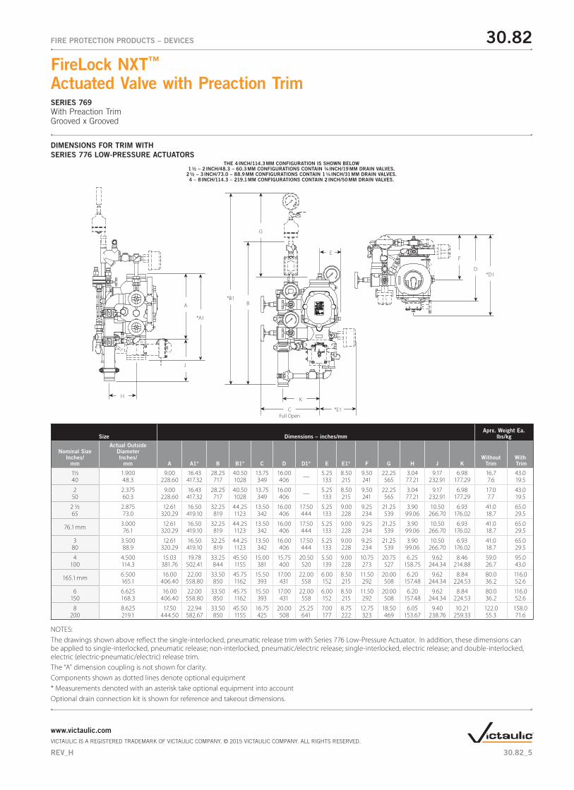
DIMENSIONS FOR TRIM WITH SERIES 776 LOW-PRESSURE ACTUATORS
THE 4 INCH/114.3 MM CONFIGURATION IS SHOWN BELOW1 ½ – 2 INCH/48.3 – 60.3 MM CONFIGURATIONS CONTAIN ¾ INCH/19 MM DRAIN VALVES.
2 ½ – 3 INCH/73.0 – 88.9 MM CONFIGURATIONS CONTAIN 1 ¼ INCH/31 MM DRAIN VALVES.4 – 8 INCH/114.3 – 219.1 MM CONFIGURATIONS CONTAIN 2 INCH/50 MM DRAIN VALVES.
Size Dimensions – inches/mmAprx. Weight Ea.
lbs/kg
Nominal SizeInches/
mm
Actual Outside DiameterInches/
mm A A1* B B1* C D D1* E E1* F G H J KWithout
TrimWith Trim
1½ 1.900 9.00 16.43 28.25 40.50 13.75 16.00 — 5.25 8.50 9.50 22.25 3.04 9.17 6.98 16.7 43.040 48.3 228.60 417.32 717 1028 349 406 133 215 241 565 77.21 232.91 177.29 7.6 19.5
2 2.375 9.00 16.43 28.25 40.50 13.75 16.00 — 5.25 8.50 9.50 22.25 3.04 9.17 6.98 17.0 43.050 60.3 228.60 417.32 717 1028 349 406 133 215 241 565 77.21 232.91 177.29 7.7 19.5
2 ½ 2.875 12.61 16.50 32.25 44.25 13.50 16.00 17.50 5.25 9.00 9.25 21.25 3.90 10.50 6.93 41.0 65.065 73.0 320.29 419.10 819 1123 342 406 444 133 228 234 539 99.06 266.70 176.02 18.7 29.5
76.1 mm 3.000 12.61 16.50 32.25 44.25 13.50 16.00 17.50 5.25 9.00 9.25 21.25 3.90 10.50 6.93 41.0 65.076.1 320.29 419.10 819 1123 342 406 444 133 228 234 539 99.06 266.70 176.02 18.7 29.5
3 3.500 12.61 16.50 32.25 44.25 13.50 16.00 17.50 5.25 9.00 9.25 21.25 3.90 10.50 6.93 41.0 65.080 88.9 320.29 419.10 819 1123 342 406 444 133 228 234 539 99.06 266.70 176.02 18.7 29.5
4 4.500 15.03 19.78 33.25 45.50 15.00 15.75 20.50 5.50 9.00 10.75 20.75 6.25 9.62 8.46 59.0 95.0100 114.3 381.76 502.41 844 1155 381 400 520 139 228 273 527 158.75 244.34 214.88 26.7 43.0
165.1 mm 6.500 16.00 22.00 33.50 45.75 15.50 17.00 22.00 6.00 8.50 11.50 20.00 6.20 9.62 8.84 80.0 116.0165.1 406.40 558.80 850 1162 393 431 558 152 215 292 508 157.48 244.34 224.53 36.2 52.6
6 6.625 16.00 22.00 33.50 45.75 15.50 17.00 22.00 6.00 8.50 11.50 20.00 6.20 9.62 8.84 80.0 116.0150 168.3 406.40 558.80 850 1162 393 431 558 152 215 292 508 157.48 244.34 224.53 36.2 52.6
8 8.625 17.50 22.94 33.50 45.50 16.75 20.00 25.25 7.00 8.75 12.75 18.50 6.05 9.40 10.21 122.0 158.0200 219.1 444.50 582.67 850 1155 425 508 641 177 222 323 469 153.67 238.76 259.33 55.3 71.6
NOTES:The drawings shown above reflect the single-interlocked, pneumatic release trim with Series 776 Low-Pressure Actuator. In addition, these dimensions can be applied to single-interlocked, pneumatic release; non-interlocked, pneumatic/electric release; single-interlocked, electric release; and double-interlocked, electric (electric-pneumatic/electric) release trim.The “A” dimension coupling is not shown for clarity.Components shown as dotted lines denote optional equipment* Measurements denoted with an asterisk take optional equipment into accountOptional drain connection kit is shown for reference and takeout dimensions.
A
J
*A1
B*B1
G
F
D*D1
CFull Open
K
*E1
E
H
30.82_5
30.82FIRE PROTECTION PRODUCTS – DEVICES
FireLock NXT™ Actuated Valve with Preaction TrimSERIES 769With Preaction TrimGrooved x Grooved
www.victaulic.comVICTAULIC IS A REGISTERED TRADEMARK OF VICTAULIC COMPANY. © 2015 VICTAULIC COMPANY. ALL RIGHTS RESERVED.
REV_H
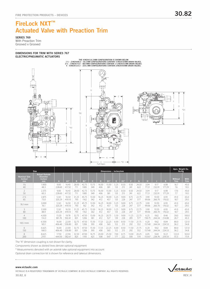
DIMENSIONS FOR TRIM WITH SERIES 767 ELECTRIC/PNEUMATIC ACTUATORS
THE 4 INCH/114.3 MM CONFIGURATION IS SHOWN BELOW1 ½ – 2 INCH/48.3 – 60.3 MM CONFIGURATIONS CONTAIN ¾ INCH/19 MM DRAIN VALVES.
2 ½ – 3 INCH/73.0 – 88.9 MM CONFIGURATIONS CONTAIN 1 ¼ INCH/31 MM DRAIN VALVES.4 – 8 INCH/114.3 – 219.1 MM CONFIGURATIONS CONTAIN 2 INCH/50 MM DRAIN VALVES.
Size Dimensions – inches/mmAprx. Weight Ea.
lbs/kg
Nominal Size Inches/
mm
Actual Outside Diameter Inches/
mm A A1* B B1* C D D1* E E1* F G H J KWithout
TrimWith Trim
1½ 1.900 9.00 16.43 28.00 42.75 13.75 16.00 15.00 5.25 8.50 9.50 24.50 3.04 9.17 6.98 16.7 43.040 48.3 228.60 417.32 711 1085 349 406 381 133 215 241 622 77.21 232.91 177.29 7.6 19.5
2 2.375 9.00 16.43 28.00 42.75 13.75 16.00 15.00 5.25 8.50 9.50 24.50 3.04 9.17 6.98 17.0 43.050 60.3 228.60 417.32 711 1085 349 406 381 133 215 241 622 77.21 232.91 177.29 7.7 19.5
2 ½ 2.875 12.61 16.50 31.25 45.75 13.50 16.25 18.00 5.25 9.00 9.75 22.75 3.90 10.50 6.93 41.0 65.065 73.0 320.29 419.10 793 1162 342 412 457 133 228 247 577 99.06 266.70 176.02 18.7 29.5
76.1 mm 3.000 12.61 16.50 31.25 45.75 13.50 16.25 18.00 5.25 9.00 9.75 22.75 3.90 10.50 6.93 41.0 65.076.1 320.29 419.10 793 162 342 412 457 133 228 247 577 99.06 266.70 176.02 18.7 29.5
3 3.500 12.61 16.50 31.25 45.75 13.50 16.25 18.00 5.25 9.00 9.75 22.75 3.90 10.50 6.93 41.0 65.080 88.9 320.29 419.10 793 1162 342 412 457 133 228 247 577 99.06 266.70 176.02 18.7 29.5
4 4.500 15.03 19.78 32.75 47.50 15.00 16.25 20.75 5.50 9.00 11.25 22.75 6.25 9.62 8.46 59.0 100.0100 114.3 381.76 502.41 831 1206 381 412 527 139 228 285 577 158.75 244.34 214.88 26.7 43.3
165.1 mm 6.500 16.00 22.00 32.75 47.50 15.50 17.25 22.25 6.00 8.50 11.50 21.75 6.20 9.62 8.84 80.0 121.0165.1 406.40 558.80 831 1206 393 438 565 152 215 292 552 157.48 244.34 224.53 36.2 54.8
6 6.625 16.00 22.00 32.75 47.50 15.50 17.25 22.25 6.00 8.50 11.50 21.75 6.20 9.62 8.84 80.0 121.0150 168.3 406.40 558.80 831 1206 393 438 565 152 215 292 552 157.48 244.34 224.53 36.2 54.8
8 8.625 17.50 22.94 32.50 47.00 16.75 20.00 25.50 7.00 8.75 13.00 20.25 6.05 9.40 10.21 122.0 163.0200 219.1 444.50 582.67 825 1193 425 508 647 177 222 330 514 153.67 238.76 259.33 55.3 73.9
The “A” dimension coupling is not shown for clarity.Components shown as dotted lines denote optional equipment* Measurements denoted with an asterisk take optional equipment into accountOptional drain connection kit is shown for reference and takeout dimensions.
A
*A1B
*B1
G
F
D
*D1
CFull Open
*E1
E
J
KH
30.82_6
30.82FIRE PROTECTION PRODUCTS – DEVICES
FireLock NXT™ Actuated Valve with Preaction TrimSERIES 769With Preaction TrimGrooved x Grooved
www.victaulic.comVICTAULIC IS A REGISTERED TRADEMARK OF VICTAULIC COMPANY. © 2015 VICTAULIC COMPANY. ALL RIGHTS RESERVED.
REV_H
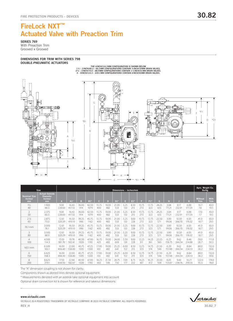
DIMENSIONS FOR TRIM WITH SERIES 798 DOUBLE-PNEUMATIC ACTUATORS
THE 4 INCH/114.3 MM CONFIGURATION IS SHOWN BELOW1 ½ – 2 INCH/48.3 – 60.3 MM CONFIGURATIONS CONTAIN ¾ INCH/19 MM DRAIN VALVES.
2 ½ – 3 INCH/73.0 – 88.9 MM CONFIGURATIONS CONTAIN 1 ¼ INCH/31 MM DRAIN VALVES.4 – 8 INCH/114.3 – 219.1 MM CONFIGURATIONS CONTAIN 2 INCH/50 MM DRAIN VALVES.
Size Dimensions – inches/mmAprx. Weight Ea.
lbs/kg
Nominal Size Inches/
mm
Actual Outside Diameter Inches/
mm A A1* B B1* C D D1* E E1* F F1* G H J KWithout
TrimWith Trim
1½ 1.900 9.00 16.43 36.00 42.50 15.75 19.00 21.00 5.25 8.50 10.75 12.75 24.25 3.04 9.17 6.98 16.7 43.040 48.3 228.60 417.32 914 1079 400 482 533 133 215 273 323 615 77.21 232.91 177.29 7.6 19.5
2 2.375 9.00 16.43 36.00 42.50 15.75 19.00 21.00 5.25 8.50 10.75 12.75 24.25 3.04 9.17 6.98 17.0 43.050 60.3 228.60 417.32 914 1079 400 482 533 133 215 273 323 615 77.21 232.91 177.29 7.7 19.5
2 ½ 2.875 12.61 16.50 39.25 45.75 15.75 19.00 21.00 5.25 9.00 10.75 12.75 22.50 3.90 10.50 6.93 41.0 65.065 73.0 320.29 419.10 996 1162 400 482 533 133 228 273 323 571 99.06 266.70 176.02 18.7 29.5
76.1 mm 3.000 12.61 16.50 39.25 45.75 15.75 19.00 21.00 5.25 9.00 10.75 12.75 22.50 3.90 10.50 6.93 41.0 65.076.1 320.29 419.10 996 1162 400 482 533 133 228 273 323 571 99.06 266.70 176.02 18.7 29.5
3 3.500 12.61 16.50 39.25 45.75 15.75 19.00 21.00 5.25 9.00 10.75 12.75 22.50 3.90 10.50 6.93 41.0 65.080 88.9 320.29 419.10 996 1162 400 482 533 133 228 273 323 571 99.06 266.70 176.02 18.7 29.5
4 4.500 15.03 19.78 40.50 47.00 16.75 19.00 24.00 5.50 9.00 12.25 14.25 22.25 6.25 9.62 8.46 59.0 111.0100 114.3 381.76 502.41 1028 1193 425 482 609 139 228 311 361 565 158.75 244.34 214.88 26.7 50.3
165.1 mm 6.500 16.00 22.00 40.75 47.25 17.00 19.00 25.25 6.00 8.50 12.75 14.75 21.50 6.20 9.62 8.84 80.0 132.0165.1 406.40 558.80 1035 1200 431 482 641 152 215 323 374 546 157.48 244.34 224.53 36.2 59.8
6 6.625 16.00 22.00 40.75 47.25 17.00 19.00 25.25 6.00 8.50 12.75 14.75 21.50 6.20 9.62 8.84 80.0 132.0150 168.3 406.40 558.80 1035 1200 431 482 641 152 215 323 374 546 157.48 244.34 224.53 36.2 59.8
8 8.625 17.50 22.94 40.50 47.00 18.25 21.50 28.75 7.00 8.75 14.25 16.25 20.00 6.05 9.40 10.21 122.0 174.0200 219.1 444.50 582.67 1028 1193 463 546 730 177 222 361 412 508 153.67 238.76 259.33 55.3 78.9
The “A” dimension coupling is not shown for clarity.Components shown as dotted lines denote optional equipment* Measurements denoted with an asterisk take optional equipment into accountOptional drain connection kit is shown for reference and takeout dimensions.
A
*A1
B
*B1
G
F *F1
D *D1
C *E1
E
J
KH
30.82_7
30.82FIRE PROTECTION PRODUCTS – DEVICES
FireLock NXT™ Actuated Valve with Preaction TrimSERIES 769With Preaction TrimGrooved x Grooved
www.victaulic.comVICTAULIC IS A REGISTERED TRADEMARK OF VICTAULIC COMPANY. © 2015 VICTAULIC COMPANY. ALL RIGHTS RESERVED.
REV_H
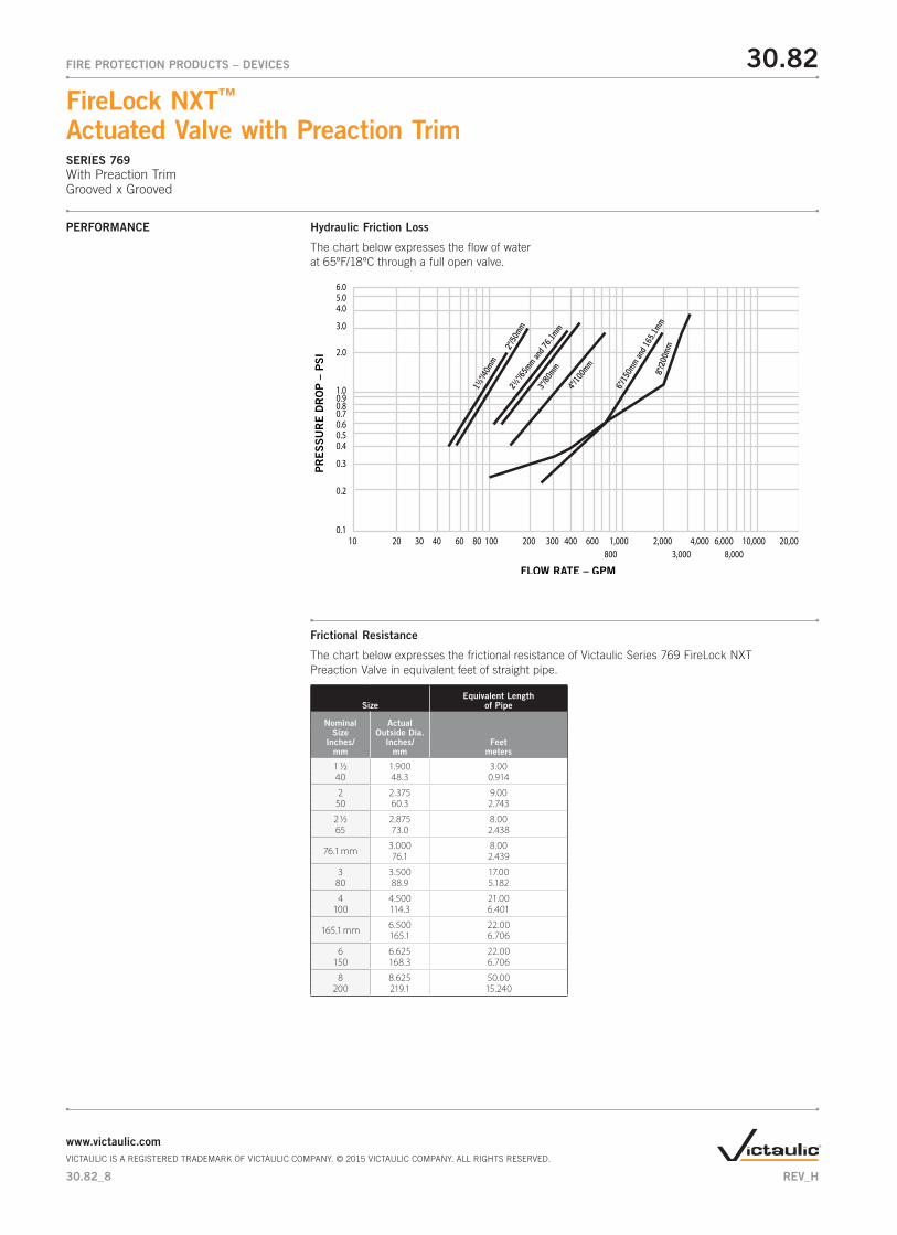
PERFORMANCE Hydraulic Friction Loss
The chart below expresses the flow of water at 65ºF/18ºC through a full open valve.
Frictional Resistance
The chart below expresses the frictional resistance of Victaulic Series 769 FireLock NXT Preaction Valve in equivalent feet of straight pipe.
SizeEquivalent Length
of Pipe
NominalSize
Inches/mm
ActualOutside Dia.
Inches/mm
Feetmeters
1 ½ 1.900 3.0040 48.3 0.914
2 2.375 9.0050 60.3 2.743
2 ½ 2.875 8.0065 73.0 2.438
76.1 mm 3.000 8.0076.1 2.439
3 3.500 17.0080 88.9 5.182
4 4.500 21.00100 114.3 6.401
165.1 mm 6.500 22.00165.1 6.706
6 6.625 22.00150 168.3 6.706
8 8.625 50.00200 219.1 15.240
PR
ES
SU
RE D
RO
P –
PSI
FLOW RATE – GPM
800 3,000 8,000
6.05.04.0
3.0
2.0
1.00.90.80.70.60.50.4
0.3
0.2
0.110 20 30 40 60 80 100 200 300 400 600 1,000 2,000 4,000 6,000 10,000 20,000
3"/80
mm
4"/10
0mm
6"/1
50mm
and 1
65.1
mm8"
/200
mm
2½"/6
5mm an
d 76.1
mm
1½"/4
0mm
2"/5
0mm
30.82_8
30.82FIRE PROTECTION PRODUCTS – DEVICES
FireLock NXT™ Actuated Valve with Preaction TrimSERIES 769With Preaction TrimGrooved x Grooved
www.victaulic.comVICTAULIC IS A REGISTERED TRADEMARK OF VICTAULIC COMPANY. © 2015 VICTAULIC COMPANY. ALL RIGHTS RESERVED.
REV_H
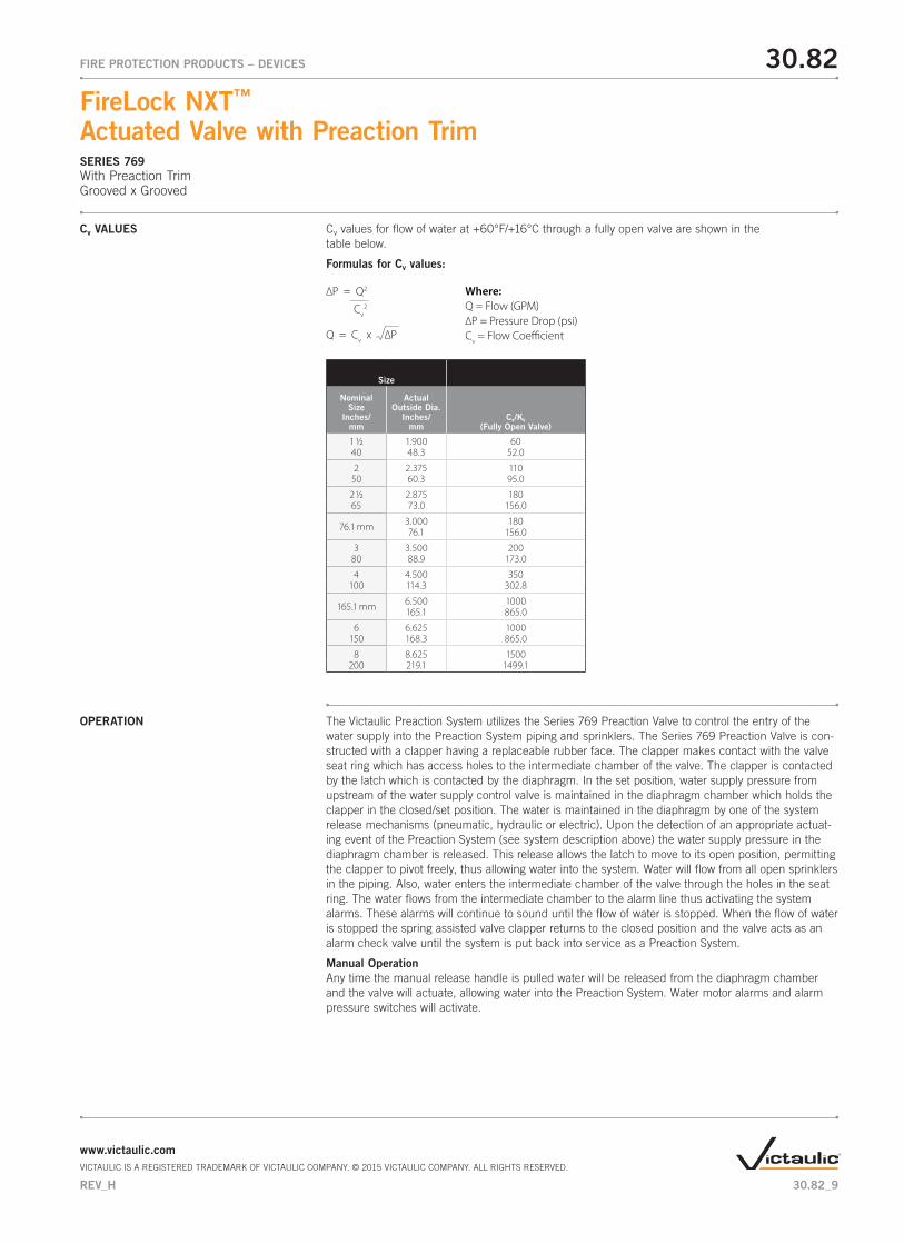
Cv VALUES Cv values for flow of water at +60°F/+16°C through a fully open valve are shown in the table below.
Formulas for Cv values:
Size
NominalSize
Inches/mm
ActualOutside Dia.
Inches/mm
Cv/Kv(Fully Open Valve)
1 ½ 1.900 6040 48.3 52.0
2 2.375 11050 60.3 95.0
2 ½ 2.875 18065 73.0 156.0
76.1 mm 3.000 18076.1 156.0
3 3.500 20080 88.9 173.0
4 4.500 350100 114.3 302.8
165.1 mm 6.500 1000165.1 865.0
6 6.625 1000150 168.3 865.0
8 8.625 1500200 219.1 1499.1
∆P = Q2
Cv2
Where:Q = Flow (GPM)∆P = Pressure Drop (psi)Cv = Flow Coe�cientQ = Cv x ∆P
OPERATION The Victaulic Preaction System utilizes the Series 769 Preaction Valve to control the entry of the water supply into the Preaction System piping and sprinklers. The Series 769 Preaction Valve is con-structed with a clapper having a replaceable rubber face. The clapper makes contact with the valve seat ring which has access holes to the intermediate chamber of the valve. The clapper is contacted by the latch which is contacted by the diaphragm. In the set position, water supply pressure from upstream of the water supply control valve is maintained in the diaphragm chamber which holds the clapper in the closed/set position. The water is maintained in the diaphragm by one of the system release mechanisms (pneumatic, hydraulic or electric). Upon the detection of an appropriate actuat-ing event of the Preaction System (see system description above) the water supply pressure in the diaphragm chamber is released. This release allows the latch to move to its open position, permitting the clapper to pivot freely, thus allowing water into the system. Water will flow from all open sprinklers in the piping. Also, water enters the intermediate chamber of the valve through the holes in the seat ring. The water flows from the intermediate chamber to the alarm line thus activating the system alarms. These alarms will continue to sound until the flow of water is stopped. When the flow of water is stopped the spring assisted valve clapper returns to the closed position and the valve acts as an alarm check valve until the system is put back into service as a Preaction System.
Manual OperationAny time the manual release handle is pulled water will be released from the diaphragm chamber and the valve will actuate, allowing water into the Preaction System. Water motor alarms and alarm pressure switches will activate.
30.82_9
30.82FIRE PROTECTION PRODUCTS – DEVICES
FireLock NXT™ Actuated Valve with Preaction TrimSERIES 769With Preaction TrimGrooved x Grooved
www.victaulic.comVICTAULIC IS A REGISTERED TRADEMARK OF VICTAULIC COMPANY. © 2015 VICTAULIC COMPANY. ALL RIGHTS RESERVED.
REV_H
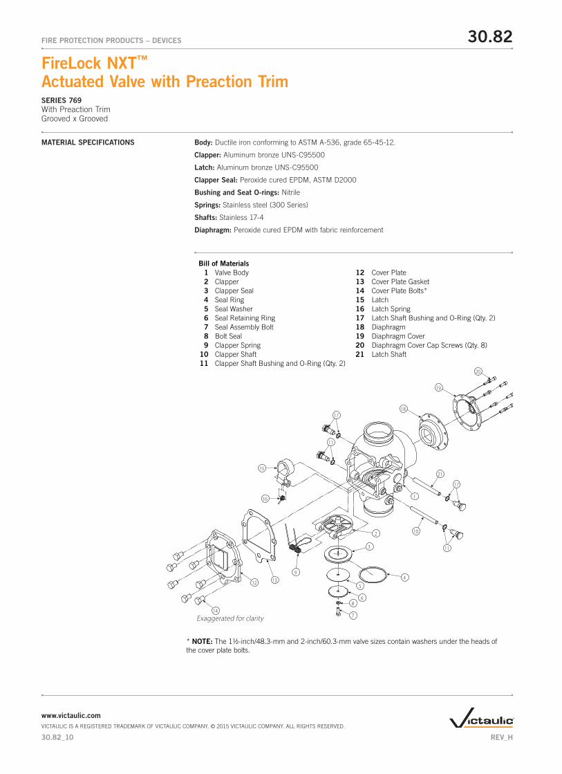
MATERIAL SPECIFICATIONS Body: Ductile iron conforming to ASTM A-536, grade 65-45-12.
Clapper: Aluminum bronze UNS-C95500
Latch: Aluminum bronze UNS-C95500
Clapper Seal: Peroxide cured EPDM, ASTM D2000
Bushing and Seat O-rings: Nitrile
Springs: Stainless steel (300 Series)
Shafts: Stainless 17-4
Diaphragm: Peroxide cured EPDM with fabric reinforcement
Bill of Materials 1 Valve Body 12 Cover Plate 2 Clapper 13 Cover Plate Gasket 3 Clapper Seal 14 Cover Plate Bolts* 4 Seal Ring 15 Latch 5 Seal Washer 16 Latch Spring 6 Seal Retaining Ring 17 Latch Shaft Bushing and O-Ring (Qty. 2) 7 Seal Assembly Bolt 18 Diaphragm 8 Bolt Seal 19 Diaphragm Cover 9 Clapper Spring 20 Diaphragm Cover Cap Screws (Qty. 8) 10 Clapper Shaft 21 Latch Shaft 11 Clapper Shaft Bushing and O-Ring (Qty. 2)
1
12
11
17
17
11
21
20
94
3
10
18
19
7
8
15
16
14
13
2
5
6
* NOTE: The 1½-inch/48.3-mm and 2-inch/60.3-mm valve sizes contain washers under the heads of the cover plate bolts.
Exaggerated for clarity
30.82_10
30.82FIRE PROTECTION PRODUCTS – DEVICES
FireLock NXT™ Actuated Valve with Preaction TrimSERIES 769With Preaction TrimGrooved x Grooved
www.victaulic.comVICTAULIC IS A REGISTERED TRADEMARK OF VICTAULIC COMPANY. © 2015 VICTAULIC COMPANY. ALL RIGHTS RESERVED.
REV_H
TRIM PACKAGES Trim Packages Options:
1 Non-Interlocked, Penumatic
2 Non-Interlocked, Pneumatic/Electric
3 Single-Interlocked, Pneumatic
4 Single-Interlocked, Electric or Double-Interlocked, Electric (Electric-Pneumatic/Electric)
5 Double-Interlocked, Electric/Pneumatic
6 Double-Interlocked, Pneumatic/Pneumatic
Trim packages include all required galvanized pipe and fittings. For trim package details and optional accessories, see pages 17-22
Actuators:
• Series 776 Low-Pressure Actuator – The Series 776 Low-Pressure Actuator is pneumati-cally actuated and requires only 13 psi/90 kPa minimum air pressure, regardless of the system supply pressure. This actuator allows the system to operate with a low air or gas pressure of 7 psi/48 kPa. Request submittal 30.65.
• Series 767 Electric/Pneumatic Actuator – The Series 767 Electric/Pneumatic Actuator provides a single trip point for the pneumatic event and an integral electric actuator. This actuator requires only 13 psi/90 kPa minimum air pressure, regardless of the system supply pressure. This actuator allows the system to operate with a low air or gas pressure of 7 psi/48 kPa. Request submittal 30.62.
• Series 798 Double-Pneumatic Actuator – The Series 798 Double-Pneumatic Actuator requires two separate pneumatic activations in order to actuate the system. This actuator requires only 13 psi/90 kPa minimum air pressure, regardless of the system supply pressure. This actuator allows the system to operate with a low air or gas pressure of 7 psi/48 kPa. Request submittal 30.61.
• Series 753-E Solenoid Valve – The Series 753-E Solenoid Valve is designed for use with systems that require electrical activation. Request submittal 30.63.
30.82_11
30.82FIRE PROTECTION PRODUCTS – DEVICES
FireLock NXT™ Actuated Valve with Preaction TrimSERIES 769With Preaction TrimGrooved x Grooved
www.victaulic.comVICTAULIC IS A REGISTERED TRADEMARK OF VICTAULIC COMPANY. © 2015 VICTAULIC COMPANY. ALL RIGHTS RESERVED.
REV_H
Optional accessories:
• Series 746-LPA Dry Accelerator – The Series 746-LPA Dry Accelerator can be used on pneumatic release systems to improve response time. Request submittal 30.64.
• Series 760 Water Motor Alarm – The Series 760 Water Motor Alarm is a mechanical device that sounds when a sustained flow of water occurs (such as with an open sprinkler). Request submittal 30.32.
• Series 75B Supplemental Alarm Device – The Series 75B Supplemental Alarm Device is designed to provide a continuous alarm for systems equipped with a mechanical device. Request submittal 30.33.
• Series 75D Water Column Kit – The Series 75D Water Column Kit is designed to minimize residual water in the riser from collecting above the clapper. Request submittal 30.34.
• Alarm Pressure Switch – Alarm Pressure Switches are designed to activate electrical alarms and control panels when a sustained flow of water occurs (such as with an open sprinkler).
• Air Supervisory Pressure Switch – Air Pressure Supervisory Switches are used to monitor system air pressure and are available as low-pressure and high-pressure sensitivity.
• Air Supply System – The air supply system contains all components for establishing and maintaining air in a pneumatic system. The compressor, low pressure alarms, ball valves, and required trim are included in the air supply system.
• Air Compressor (See page 14 for more on the Victaulic Series 7C7 Compressor Package)
• Air Maintenance Trim Assembly
• Alarm Panels
• Drain Connection Kit
TRIM PACKAGES
30.82_12
30.82FIRE PROTECTION PRODUCTS – DEVICES
FireLock NXT™ Actuated Valve with Preaction TrimSERIES 769With Preaction TrimGrooved x Grooved
www.victaulic.comVICTAULIC IS A REGISTERED TRADEMARK OF VICTAULIC COMPANY. © 2015 VICTAULIC COMPANY. ALL RIGHTS RESERVED.
REV_H
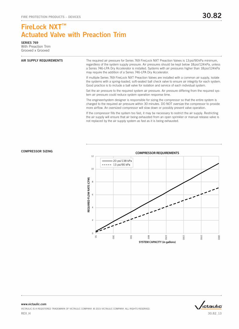
AIR SUPPLY REQUIREMENTS The required air pressure for Series 769 FireLock NXT Preaction Valves is 13 psi/90 kPa minimum, regardless of the system supply pressure. Air pressures should be kept below 18 psi/124 kPa, unless a Series 746-LPA Dry Accelerator is installed. Systems with air pressures higher than 18 psi/124 kPa may require the addition of a Series 746-LPA Dry Accelerator.
If multiple Series 769 FireLock NXT Preaction Valves are installed with a common air supply, isolate the systems with a spring-loaded, soft-seated ball check valve to ensure air integrity for each system. Good practice is to include a ball valve for isolation and service of each individual system.
Set the air pressure to the required system air pressure. Air pressure differing from the required sys-tem air pressure could reduce system operation response time.
The engineer/system designer is responsible for sizing the compressor so that the entire system is charged to the required air pressure within 30 minutes. DO NOT oversize the compressor to provide more airflow. An oversized compressor will slow down or possibly prevent valve operation.
If the compressor fills the system too fast, it may be necessary to restrict the air supply. Restricting the air supply will ensure that air being exhausted from an open sprinkler or manual release valve is not replaced by the air supply system as fast as it is being exhausted.
COMPRESSOR SIZING
0
2
4
6
8
10
12
SYSTEM CAPACITY (in gallons)
REQ
UIR
ED F
LOW
RAT
E (C
FM)
COMPRESSOR REQUIREMENTS
55
0
30
0
50
80
0
10
50
13
00
15
50
18
00
20 psi/138 kPa13 psi/90 kPa
30.82_13
30.82FIRE PROTECTION PRODUCTS – DEVICES
FireLock NXT™ Actuated Valve with Preaction TrimSERIES 769With Preaction TrimGrooved x Grooved
www.victaulic.comVICTAULIC IS A REGISTERED TRADEMARK OF VICTAULIC COMPANY. © 2015 VICTAULIC COMPANY. ALL RIGHTS RESERVED.
REV_H
BASE OR RISER-MOUNTED COMPRESSORS
For base or riser-mounted compressors, the recommended air pressure of 13 psi/90 kPa is the “on” or “low” pressure setting for the compressor. The “off” or “high” pressure setting should be 18 psi/124 kPa. Victaulic offers the Series 7C7 Compressor package for FireLock NXT devices which is riser-mounted and pre-set for the FireLock NXT pressure requirements as stated above. For information on the Series 7C7 package, consult publication 30.22. The Series 7C7 Compressor package is only available in North America.
When a base or riser-mounted air compressor supplies air to a Series 768 FireLock NXT Dry Valve, it is not necessary to install the Victaulic Series 757 Regulated Air Maintenance Trim Assembly (AMTA). In this case, the airline of the compressor connects to the trim at the fitting where the Series 757 Regulated AMTA is normally installed (refer to the applicable trim drawing). If the compres-sor is not equipped with a pressure switch, the Series 757P Air Maintenance Trim Assembly with Pressure Switch should be installed. For information on the Series 757 Regulated Air Maintenance Trim Assembly, see publication 30.35. For information on the Series 757P Air Maintenance Trim Assembly, see publication 30.36.
In the event a compressor becomes inoperative, a properly sized tank-mounted air compressor p rovides the the greatest protection for systems.
When shop air or a tank-mounted air compressor is used, the Series 757 Regulated AMTA must be installed. The Series 757 Regulated AMTA provides proper air regulation from the air reservoir to the sprinkler system.
For tank-mounted air compressors, the recommended air pressure of 13 psi/90 kPa should be used as the set point for the air regulator. The “on” pressure of the compressor should be at least 5 psi/34 kPa above the set point of the air regulator.
SHOP AIR OR TANK-MOUNTED AIR COMPRESSORS
30.82_14
30.82FIRE PROTECTION PRODUCTS – DEVICES
FireLock NXT™ Actuated Valve with Preaction TrimSERIES 769With Preaction TrimGrooved x Grooved
www.victaulic.comVICTAULIC IS A REGISTERED TRADEMARK OF VICTAULIC COMPANY. © 2015 VICTAULIC COMPANY. ALL RIGHTS RESERVED.
REV_H
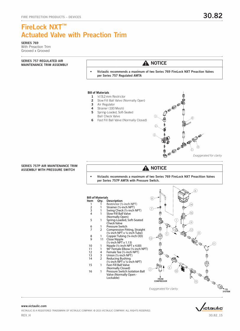
SERIES 757 REGULATED AIR MAINTENANCE TRIM ASSEMBLY
16
54
2
3
Bill of Materials 1 1⁄8"/3.2 mm Restrictor 2 Slow Fill Ball Valve (Normally Open) 3 Air Regulator 4 Strainer (100 Mesh) 5 Spring-Loaded, Soft-Seated Ball Check Valve 6 Fast Fill Ball Valve (Normally Closed)
SERIES 757P AIR MAINTENANCE TRIM ASSEMBLY WITH PRESSURE SWITCH
NOTICE
• Victaulic recommends a maximum of two Series 769 FireLock NXT Preaction Valves per Series 757 Regulated AMTA
NOTICE
• Victaulic recommends a maximum of two Series 769 FireLock NXT Preacttion Valves per Series 757P AMTA with Pressure Switch.
Exaggerated for clarity
Exaggerated for clarity
5
2
12
7
8
15
10
16
9
6
4
1
13
3
14
11
TOSYSTEM
FROM COMPRESSOR
Bill of MaterialsItem Qty. Description 1 1 Restrictor (½-inch NPT) 2 1 Strainer (½-inch NPT) 3 1 Swing Check (½-inch NPT) 4 1 Slow-Fill Ball Valve (Normally Open) 5 1 Spring-Loaded, Soft-Seated Check Valve 6 1 Pressure Switch 7 2 Compression Fitting, Straight (¼-inch NPT x ¼-inch Tube) 8 1 Copper Tubing (¼-inch OD) 9 11 Close Nipple (½-inch NPT x 1.13) 10 1 Nipple (½-inch NPT x 4.00) 11 1 90° Female Elbow (½-inch NPT) 12 4 Female Tee (½-inch NPT) 13 3 Union (½-inch NPT) 14 2 Reducing Bushing (½-inch NPT x ¼-inch NPT) 15 1 Fast-Fill Ball Valve (Normally Closed) 16 1 Pressure Switch Isolation Ball Valve (Normally Open - Lockable)
30.82_15
30.82FIRE PROTECTION PRODUCTS – DEVICES
FireLock NXT™ Actuated Valve with Preaction TrimSERIES 769With Preaction TrimGrooved x Grooved
www.victaulic.comVICTAULIC IS A REGISTERED TRADEMARK OF VICTAULIC COMPANY. © 2015 VICTAULIC COMPANY. ALL RIGHTS RESERVED.
REV_H
COMPRESSOR REQUIREMENTS Compressor Requirements and Settings for Series 769 FireLock NXT Preaction Valves Installed with Series 746-LPA Dry Accelerators
Set the air regulator of the Series 757 Regulated AMTA to 13 psi/90 kPa.
THE SERIES 757P AIR MAINTENANCE TRIM ASSEMBLY WITH PRESSURE SWITCH MUST NOT BE USED ON A SERIES 769 FIRELOCK NXT PREACTION VALVE INSTALLED WITH A SERIES 746-LPA DRY ACCELERATOR.
When a Series 769 FireLock NXT Preaction Valve is installed with a Series 746-LPA Dry Accelerator, the Series 757 Regulated AMTA must be used. NOTE: The use of an air regulator with a base or riser-mounted compressor could cause short cycling, resulting in premature wear of the compressor.
In the event a compressor becomes inoperative, a properly sized tank-mounted air compressor provides the greatest protection for systems installed with a Series 746-LPA Dry Accelerator. In this situation, air can be supplied continuously to the sprinkler system for an extended time period. NOTE: The Series 757 Regulated AMTA must be used with a tank-mounted air compressor that supplies air to a Series 769 FireLock NXT Preaction Valve installed with a Series 746-LPA Dry Accelerator.
The air regulator of the Series 757 Regulated AMTA is a relief-type design. Any pressure in the system that is above the set point of the air regulator will be released. Therefore, charging the air reg-ulator above the set point could cause premature operation of a valve installed with a Series 746-LPA Dry Accelerator. NOTE: The Series 746-LPA should not be used above 30 psi/207kPa. If higher pres-sures are required, the Series 746 should be used.
Settings for Air Supervisory Pressure Switches and Alarm Pressure Switches
Air supervisory pressure switches are required for preaction systems and must be set according to the following instructions. NOTE: Switches for Vic-Quick Risers are pre-set at the factory.
Wire the air supervisory pressure switches to activate a low-pressure alarm signal. NOTE: In addition, the local authority having jurisdiction may require a high-pressure alarm. Contact the local authority having jurisdiction for this requirement.
Set the air supervisory pressure switches to activate at 2 – 4 psi/14 – 28 kPa below the minimum air pressure required, but not lower than 10 psi/69 kPa.
Wire the alarm pressure switch to activate a water flow alarm.
Set the alarm pressure switch to activate on a pressure rise of 4 – 8 psi/28 – 55 kPa.
Remote System Test Valve Requirements
The remote system test valve (inspector’s test connection) should contain a UL Listed and/or FM Approved valve (normally closed), which can be opened to simulate the operation of a sprinkler.
The remote system test valve (inspector’s test connection) should be located at the most hydrauli-cally demanding location in the release system. NOTE: Multiple restrictions on the remote system test valve (inspector’s test connection) may slow the air decay rate and cause the system to respond slower than required.
The remote system test valve (inspector’s test connection) should terminate with an orifice equal to the smallest orifice in the releasing system.
The remote system test valve (inspector’s test connection) is used to ensure that water reaches the most remote part of the system within 60 seconds.
30.82_16
30.82FIRE PROTECTION PRODUCTS – DEVICES
FireLock NXT™ Actuated Valve with Preaction TrimSERIES 769With Preaction TrimGrooved x Grooved
www.victaulic.comVICTAULIC IS A REGISTERED TRADEMARK OF VICTAULIC COMPANY. © 2015 VICTAULIC COMPANY. ALL RIGHTS RESERVED.
REV_H
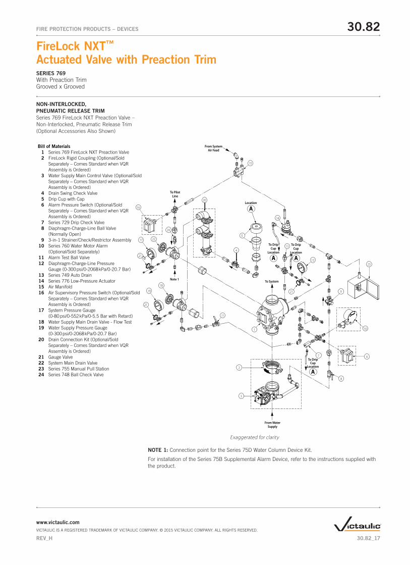
NON-INTERLOCKED, PNEUMATIC RELEASE TRIMSeries 769 FireLock NXT Preaction Valve – Non-Interlocked, Pneumatic Release Trim(Optional Accessories Also Shown)
Exaggerated for clarity
NOTE 1: Connection point for the Series 75D Water Column Device Kit.
For installation of the Series 75B Supplemental Alarm Device, refer to the instructions supplied with the product.
From WaterSupply
2
3
1
11
20
22
24
14
13
21
16
19
21
17
18
21
15
6
10
2312
8
4
7
9
From SystemAir Feed
To System
To PilotLine
5
ALocation
A
To DripCup
Location
A
To DripCup
Location
A
To DripCup
Location
Bill of Materials 1 Series 769 FireLock NXT Preaction Valve 2 FireLock Rigid Coupling (Optional/Sold Separately – Comes Standard when VQR Assembly is Ordered) 3 Water Supply Main Control Valve (Optional/Sold Separately – Comes Standard when VQR Assembly is Ordered) 4 Drain Swing Check Valve 5 Drip Cup with Cap 6 Alarm Pressure Switch (Optional/Sold Separately – Comes Standard when VQR Assembly is Ordered) 7 Series 729 Drip Check Valve 8 Diaphragm-Charge-Line Ball Valve (Normally Open) 9 3-in-1 Strainer/Check/Restrictor Assembly 10 Series 760 Water Motor Alarm (Optional/Sold Separately) 11 Alarm Test Ball Valve 12 Diaphragm-Charge-Line Pressure Gauge (0-300 psi/0-2068 kPa/0-20.7 Bar) 13 Series 749 Auto Drain 14 Series 776 Low-Pressure Actuator 15 Air Manifold 16 Air Supervisory Pressure Switch (Optional/Sold Separately – Comes Standard when VQR Assembly is Ordered) 17 System Pressure Gauge (0-80 psi/0-552 kPa/0-5.5 Bar with Retard) 18 Water Supply Main Drain Valve - Flow Test 19 Water Supply Pressure Gauge (0-300 psi/0-2068 kPa/0-20.7 Bar) 20 Drain Connection Kit (Optional/Sold Separately – Comes Standard when VQR Assembly is Ordered) 21 Gauge Valve 22 System Main Drain Valve 23 Series 755 Manual Pull Station 24 Series 748 Ball Check Valve
Note 1
30.82_17
30.82FIRE PROTECTION PRODUCTS – DEVICES
FireLock NXT™ Actuated Valve with Preaction TrimSERIES 769With Preaction TrimGrooved x Grooved
www.victaulic.comVICTAULIC IS A REGISTERED TRADEMARK OF VICTAULIC COMPANY. © 2015 VICTAULIC COMPANY. ALL RIGHTS RESERVED.
REV_H
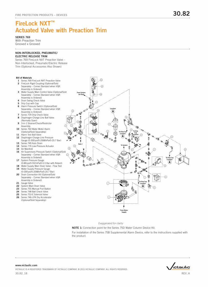
NON-INTERLOCKED, PNEUMATIC/ELECTRIC RELEASE TRIMSeries 769 FireLock NXT Preaction Valve – Non-Interlocked, Pneumatic/Electric Release Trim (Optional Accessories Also Shown)
Exaggerated for clarity
NOTE 1: Connection point for the Series 75D Water Column Device Kit.
For installation of the Series 75B Supplemental Alarm Device, refer to the instructions supplied with the product.
2
3
From WaterSupply
1
11
20
22
24
14
13
21
16
19
21
17
18
21
15
6
10
23
26
1225
8
4
7
9
From SystemAir Feed
To System
5
ALocation
A
To Drip CupLocation
A
To Drip CupLocation
A
To Drip CupLocation
A
To DripCup
Location
Bill of Materials 1 Series 769 FireLock NXT Preaction Valve 2 FireLock Rigid Coupling (Optional/Sold Separately – Comes Standard when VQR Assembly is Ordered) 3 Water Supply Main Control Valve (Optional/Sold Separately – Comes Standard when VQR Assembly is Ordered) 4 Drain Swing Check Valve 5 Drip Cup with Cap 6 Alarm Pressure Switch (Optional/Sold Separately – Comes Standard when VQR Assembly is Ordered) 7 Series 729 Drip Check Valve 8 Diaphragm-Charge-Line Ball Valve (Normally Open) 9 3-in-1 Strainer/Check/Restrictor Assembly 10 Series 760 Water Motor Alarm (Optional/Sold Separately) 11 Alarm Test Ball Valve 12 Diaphragm-Charge-Line Pressure Gauge (0-300 psi/0-2068 kPa/0-20.7 Bar) 13 Series 749 Auto Drain 14 Series 776 Low-Pressure Actuator 15 Air Manifold 16 Air Supervisory Pressure Switch (Optional/Sold Separately – Comes Standard when VQR Assembly is Ordered) 17 System Pressure Gauge (0-80 psi/0-552 kPa/0-5.5 Bar with Retard) 18 Water Supply Main Drain Valve - Flow Test 19 Water Supply Pressure Gauge (0-300 psi/0-2068 kPa/0-20.7 Bar) 20 Drain Connection Kit (Optional/Sold Separately – Comes Standard when VQR Assembly is Ordered) 21 Gauge Valve 22 System Main Drain Valve 23 Series 755 Manual Pull Station 24 Series 748 Ball Check Valve 25 Series 753-E Solenoid Valve 26 Series 746-LPA Dry Accelerator (Optional/Sold Separately)
Note 1
26b
26a
30.82_18
30.82FIRE PROTECTION PRODUCTS – DEVICES
FireLock NXT™ Actuated Valve with Preaction TrimSERIES 769With Preaction TrimGrooved x Grooved
www.victaulic.comVICTAULIC IS A REGISTERED TRADEMARK OF VICTAULIC COMPANY. © 2015 VICTAULIC COMPANY. ALL RIGHTS RESERVED.
REV_H
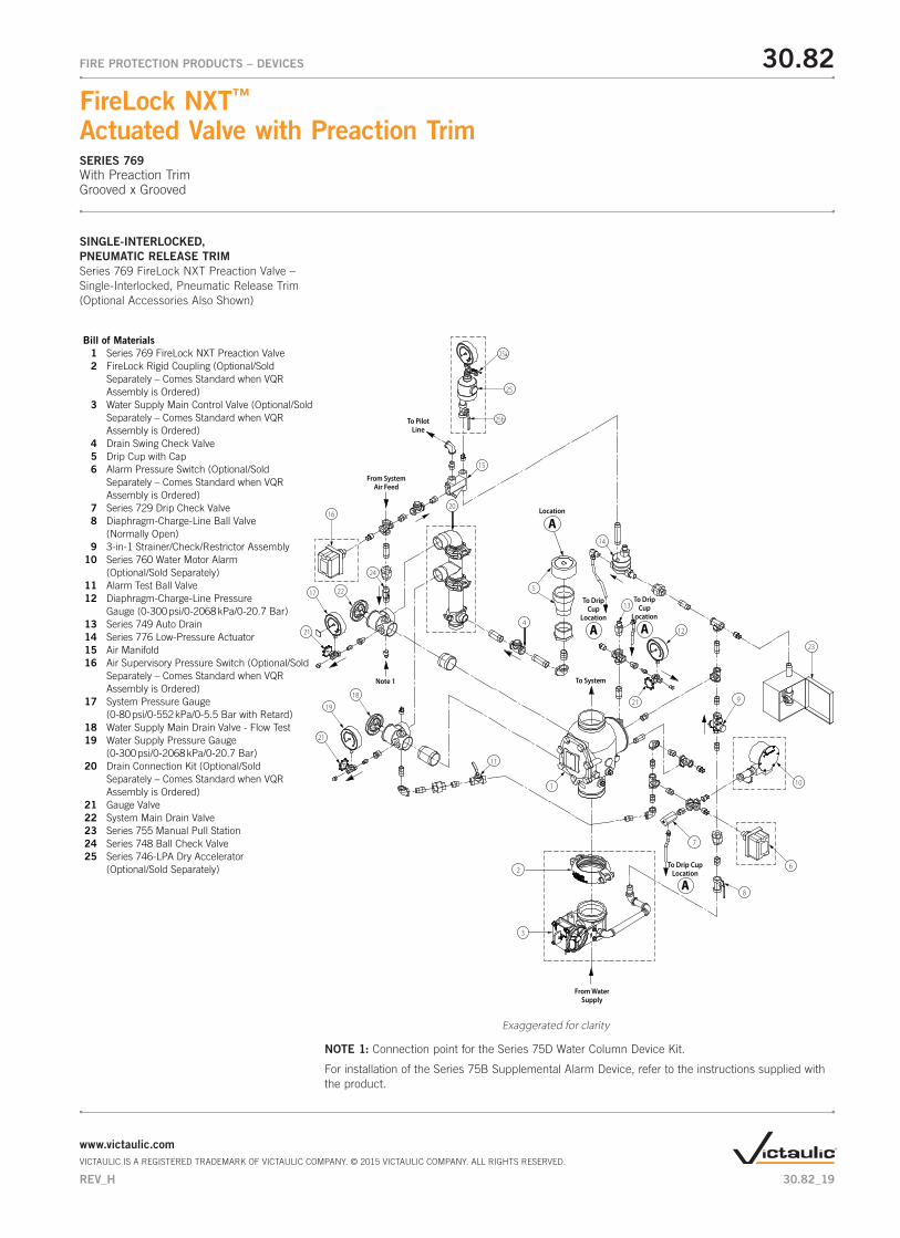
SINGLE-INTERLOCKED, PNEUMATIC RELEASE TRIMSeries 769 FireLock NXT Preaction Valve – Single-Interlocked, Pneumatic Release Trim(Optional Accessories Also Shown)
Exaggerated for clarity
NOTE 1: Connection point for the Series 75D Water Column Device Kit.
For installation of the Series 75B Supplemental Alarm Device, refer to the instructions supplied with the product.
ALocation
2
3
From WaterSupply
1
11
20
22
14
13
21
16
19
21
17
18
5
21
15
6
10
23
25
12
8
4
7
9
To PilotLine
From SystemAir Feed
To System
24
A
To DripCup
Location
A
To DripCup
Location
A
To Drip CupLocation
Bill of Materials 1 Series 769 FireLock NXT Preaction Valve 2 FireLock Rigid Coupling (Optional/Sold Separately – Comes Standard when VQR Assembly is Ordered) 3 Water Supply Main Control Valve (Optional/Sold Separately – Comes Standard when VQR Assembly is Ordered) 4 Drain Swing Check Valve 5 Drip Cup with Cap 6 Alarm Pressure Switch (Optional/Sold Separately – Comes Standard when VQR Assembly is Ordered) 7 Series 729 Drip Check Valve 8 Diaphragm-Charge-Line Ball Valve (Normally Open) 9 3-in-1 Strainer/Check/Restrictor Assembly 10 Series 760 Water Motor Alarm (Optional/Sold Separately) 11 Alarm Test Ball Valve 12 Diaphragm-Charge-Line Pressure Gauge (0-300 psi/0-2068 kPa/0-20.7 Bar) 13 Series 749 Auto Drain 14 Series 776 Low-Pressure Actuator 15 Air Manifold 16 Air Supervisory Pressure Switch (Optional/Sold Separately – Comes Standard when VQR Assembly is Ordered) 17 System Pressure Gauge (0-80 psi/0-552 kPa/0-5.5 Bar with Retard) 18 Water Supply Main Drain Valve - Flow Test 19 Water Supply Pressure Gauge (0-300 psi/0-2068 kPa/0-20.7 Bar) 20 Drain Connection Kit (Optional/Sold Separately – Comes Standard when VQR Assembly is Ordered) 21 Gauge Valve 22 System Main Drain Valve 23 Series 755 Manual Pull Station 24 Series 748 Ball Check Valve 25 Series 746-LPA Dry Accelerator (Optional/Sold Separately)
Note 1
25b
25a
30.82_19
30.82FIRE PROTECTION PRODUCTS – DEVICES
FireLock NXT™ Actuated Valve with Preaction TrimSERIES 769With Preaction TrimGrooved x Grooved
www.victaulic.comVICTAULIC IS A REGISTERED TRADEMARK OF VICTAULIC COMPANY. © 2015 VICTAULIC COMPANY. ALL RIGHTS RESERVED.
REV_H
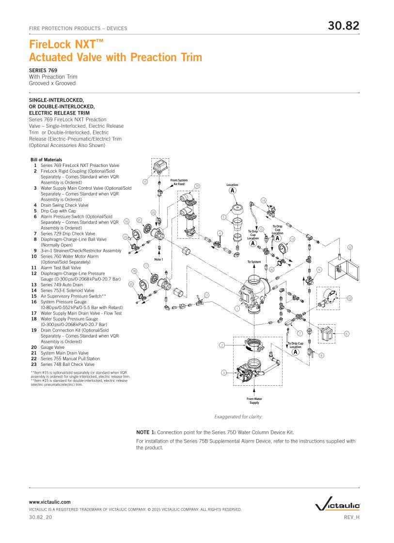
SINGLE-INTERLOCKED, OR DOUBLE-INTERLOCKED,ELECTRIC RELEASE TRIMSeries 769 FireLock NXT Preaction Valve – Single-Interlocked, Electric Release Trim or Double-Interlocked, Electric Release (Electric-Pneumatic/Electric) Trim (Optional Accessories Also Shown)
Exaggerated for clarity
NOTE 1: Connection point for the Series 75D Water Column Device Kit.
For installation of the Series 75B Supplemental Alarm Device, refer to the instructions supplied with the product.
2
3
From WaterSupply
1
15
11
21
23
14
13
20
18
20
16
17
5
20
19
6
10
22
12
8
4
7
9
From SystemAir Feed
To System
ALocation
A
To DripCup
Location A
To DripCup
Location
ATo Drip Cup
Location
Note 1
Bill of Materials 1 Series 769 FireLock NXT Preaction Valve 2 FireLock Rigid Coupling (Optional/Sold Separately – Comes Standard when VQR Assembly is Ordered) 3 Water Supply Main Control Valve (Optional/Sold Separately – Comes Standard when VQR Assembly is Ordered) 4 Drain Swing Check Valve 5 Drip Cup with Cap 6 Alarm Pressure Switch (Optional/Sold Separately – Comes Standard when VQR Assembly is Ordered) 7 Series 729 Drip Check Valve 8 Diaphragm-Charge-Line Ball Valve (Normally Open) 9 3-in-1 Strainer/Check/Restrictor Assembly 10 Series 760 Water Motor Alarm (Optional/Sold Separately) 11 Alarm Test Ball Valve 12 Diaphragm-Charge-Line Pressure Gauge (0-300 psi/0-2068 kPa/0-20.7 Bar) 13 Series 749 Auto Drain 14 Series 753-E Solenoid Valve 15 Air Supervisory Pressure Switch** 16 System Pressure Gauge (0-80 psi/0-552 kPa/0-5.5 Bar with Retard) 17 Water Supply Main Drain Valve - Flow Test 18 Water Supply Pressure Gauge (0-300 psi/0-2068 kPa/0-20.7 Bar) 19 Drain Connection Kit (Optional/Sold Separately – Comes Standard when VQR Assembly is Ordered) 20 Gauge Valve 21 System Main Drain Valve 22 Series 755 Manual Pull Station 23 Series 748 Ball Check Valve
**Item #15 is optional/sold separately (or standard when VQR assembly is ordered) for single-interlocked, electric release trim.**Item #15 is standard for double-interlocked, electric release (electric-pneumatic/electric) trim.
30.82_20
30.82FIRE PROTECTION PRODUCTS – DEVICES
FireLock NXT™ Actuated Valve with Preaction TrimSERIES 769With Preaction TrimGrooved x Grooved
www.victaulic.comVICTAULIC IS A REGISTERED TRADEMARK OF VICTAULIC COMPANY. © 2015 VICTAULIC COMPANY. ALL RIGHTS RESERVED.
REV_H
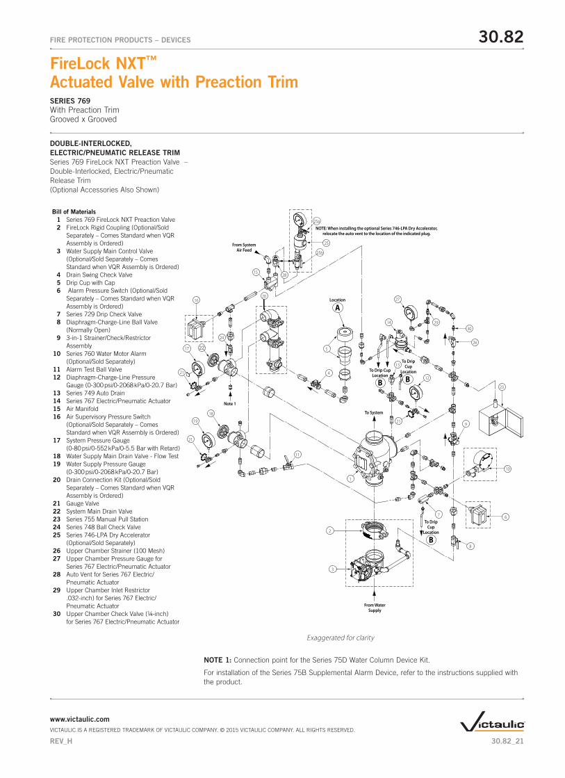
DOUBLE-INTERLOCKED, ELECTRIC/PNEUMATIC RELEASE TRIMSeries 769 FireLock NXT Preaction Valve – Double-Interlocked, Electric/Pneumatic Release Trim(Optional Accessories Also Shown)
Exaggerated for clarity
NOTE 1: Connection point for the Series 75D Water Column Device Kit.
For installation of the Series 75B Supplemental Alarm Device, refer to the instructions supplied with the product.
2
3
From WaterSupply
30
1
11
20
22
24
14
27
13
21
16
19
21
17
18
5
21
15
6
10
23
26
25
12
8
4
29
28
7
9
From SystemAir Feed
To System
NOTE: When installing the optional Series 746-LPA Dry Accelerator, relocate the auto vent to the location of the indicated plug.
ALocation
B
To Drip CupLocation B
To DripCup
Location
B
To DripCup
Location
25a
25b
Bill of Materials 1 Series 769 FireLock NXT Preaction Valve 2 FireLock Rigid Coupling (Optional/Sold Separately – Comes Standard when VQR Assembly is Ordered) 3 Water Supply Main Control Valve (Optional/Sold Separately – Comes Standard when VQR Assembly is Ordered) 4 Drain Swing Check Valve 5 Drip Cup with Cap 6 Alarm Pressure Switch (Optional/Sold Separately – Comes Standard when VQR Assembly is Ordered) 7 Series 729 Drip Check Valve 8 Diaphragm-Charge-Line Ball Valve (Normally Open) 9 3-in-1 Strainer/Check/Restrictor Assembly 10 Series 760 Water Motor Alarm (Optional/Sold Separately) 11 Alarm Test Ball Valve 12 Diaphragm-Charge-Line Pressure Gauge (0-300 psi/0-2068 kPa/0-20.7 Bar) 13 Series 749 Auto Drain 14 Series 767 Electric/Pneumatic Actuator 15 Air Manifold 16 Air Supervisory Pressure Switch (Optional/Sold Separately – Comes Standard when VQR Assembly is Ordered) 17 System Pressure Gauge (0-80 psi/0-552 kPa/0-5.5 Bar with Retard) 18 Water Supply Main Drain Valve - Flow Test 19 Water Supply Pressure Gauge (0-300 psi/0-2068 kPa/0-20.7 Bar) 20 Drain Connection Kit (Optional/Sold Separately – Comes Standard when VQR Assembly is Ordered) 21 Gauge Valve 22 System Main Drain Valve 23 Series 755 Manual Pull Station 24 Series 748 Ball Check Valve 25 Series 746-LPA Dry Accelerator (Optional/Sold Separately) 26 Upper Chamber Strainer (100 Mesh) 27 Upper Chamber Pressure Gauge for Series 767 Electric/Pneumatic Actuator 28 Auto Vent for Series 767 Electric/ Pneumatic Actuator 29 Upper Chamber Inlet Restrictor .032-inch) for Series 767 Electric/ Pneumatic Actuator 30 Upper Chamber Check Valve (¼-inch) for Series 767 Electric/Pneumatic Actuator
Note 1
30.82_21
30.82FIRE PROTECTION PRODUCTS – DEVICES
FireLock NXT™ Actuated Valve with Preaction TrimSERIES 769With Preaction TrimGrooved x Grooved
www.victaulic.comVICTAULIC IS A REGISTERED TRADEMARK OF VICTAULIC COMPANY. © 2015 VICTAULIC COMPANY. ALL RIGHTS RESERVED.
REV_H
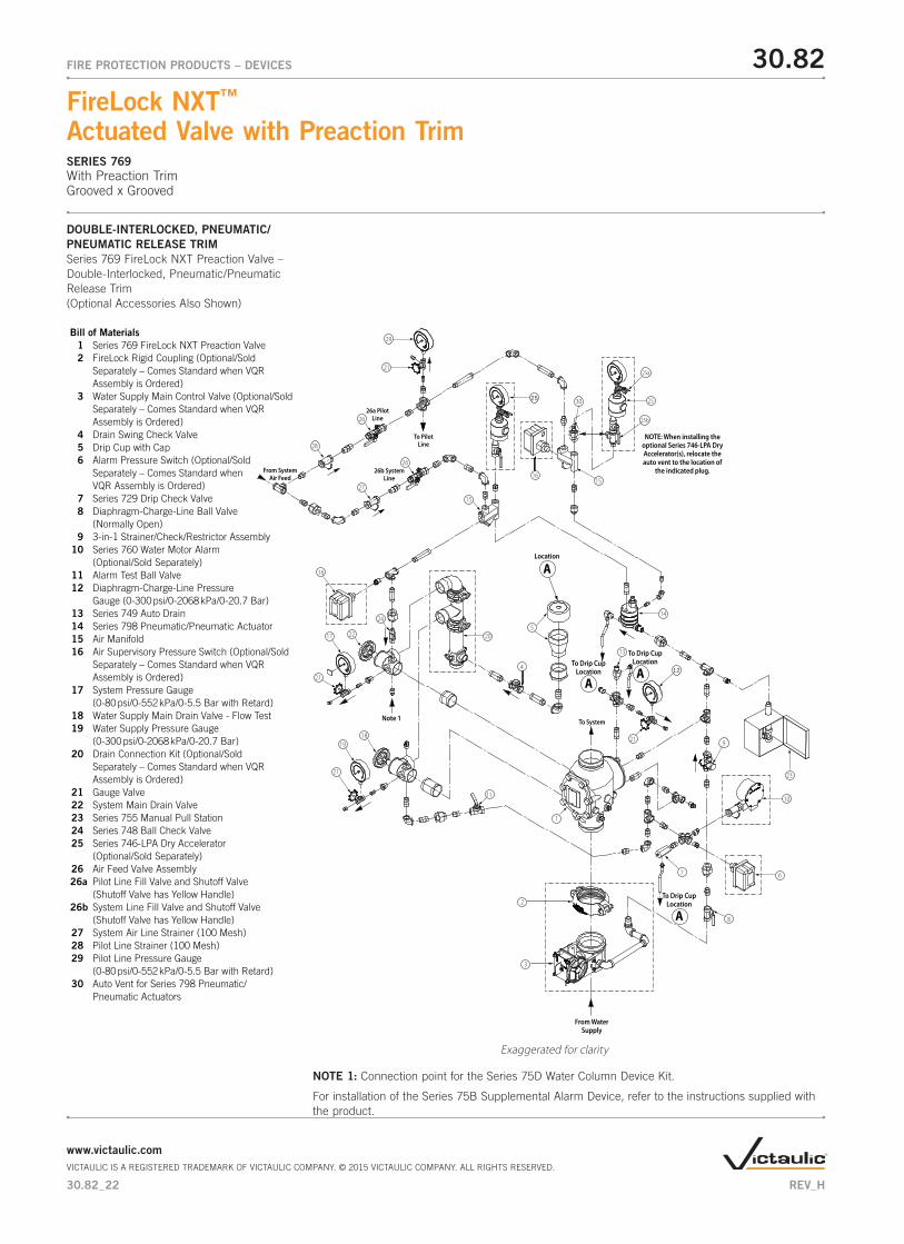
DOUBLE-INTERLOCKED, PNEUMATIC/PNEUMATIC RELEASE TRIMSeries 769 FireLock NXT Preaction Valve – Double-Interlocked, Pneumatic/Pneumatic Release Trim(Optional Accessories Also Shown)
Exaggerated for clarity
NOTE 1: Connection point for the Series 75D Water Column Device Kit.
For installation of the Series 75B Supplemental Alarm Device, refer to the instructions supplied with the product.
A
To Drip CupLocation
From WaterSupply
NOTE: When installing the optional Series 746-LPA Dry Accelerator(s), relocate the auto vent to the location of
the indicated plug.
1
21
11
16
22
24
26
28
27
26
13
21
16
19
21
21
17
18
5
15
6
10
23
14
20
29
25
15
3025
12
8
4
7
9
From SystemAir Feed
To PilotLine
To System
26a PilotLine
26b SystemLine
2
3
A
To Drip CupLocation
A
To Drip CupLocation
25a
25b
ALocation
Bill of Materials 1 Series 769 FireLock NXT Preaction Valve 2 FireLock Rigid Coupling (Optional/Sold Separately – Comes Standard when VQR Assembly is Ordered) 3 Water Supply Main Control Valve (Optional/Sold Separately – Comes Standard when VQR Assembly is Ordered) 4 Drain Swing Check Valve 5 Drip Cup with Cap 6 Alarm Pressure Switch (Optional/Sold Separately – Comes Standard when VQR Assembly is Ordered) 7 Series 729 Drip Check Valve 8 Diaphragm-Charge-Line Ball Valve (Normally Open) 9 3-in-1 Strainer/Check/Restrictor Assembly 10 Series 760 Water Motor Alarm (Optional/Sold Separately) 11 Alarm Test Ball Valve 12 Diaphragm-Charge-Line Pressure Gauge (0-300 psi/0-2068 kPa/0-20.7 Bar) 13 Series 749 Auto Drain 14 Series 798 Pneumatic/Pneumatic Actuator 15 Air Manifold 16 Air Supervisory Pressure Switch (Optional/Sold Separately – Comes Standard when VQR Assembly is Ordered) 17 System Pressure Gauge (0-80 psi/0-552 kPa/0-5.5 Bar with Retard) 18 Water Supply Main Drain Valve - Flow Test 19 Water Supply Pressure Gauge (0-300 psi/0-2068 kPa/0-20.7 Bar) 20 Drain Connection Kit (Optional/Sold Separately – Comes Standard when VQR Assembly is Ordered) 21 Gauge Valve 22 System Main Drain Valve 23 Series 755 Manual Pull Station 24 Series 748 Ball Check Valve 25 Series 746-LPA Dry Accelerator (Optional/Sold Separately) 26 Air Feed Valve Assembly 26a Pilot Line Fill Valve and Shutoff Valve (Shutoff Valve has Yellow Handle) 26b System Line Fill Valve and Shutoff Valve (Shutoff Valve has Yellow Handle) 27 System Air Line Strainer (100 Mesh) 28 Pilot Line Strainer (100 Mesh) 29 Pilot Line Pressure Gauge (0-80 psi/0-552 kPa/0-5.5 Bar with Retard) 30 Auto Vent for Series 798 Pneumatic/ Pneumatic Actuators
Note 1
30.82_22
30.82FIRE PROTECTION PRODUCTS – DEVICES
FireLock NXT™ Actuated Valve with Preaction TrimSERIES 769With Preaction TrimGrooved x Grooved
www.victaulic.comVICTAULIC IS A REGISTERED TRADEMARK OF VICTAULIC COMPANY. © 2015 VICTAULIC COMPANY. ALL RIGHTS RESERVED.
REV_H
30.82
FireLock NXT™ Actuated Valve with Preaction TrimSERIES 769With Preaction TrimGrooved x Grooved
30.82FIRE PROTECTION PRODUCTS – DEVICES
For complete contact information, visit www.victaulic.com30.82 4220 REV H UPDATED 11/2011VICTAULIC IS A REGISTERED TRADEMARK OF VICTAULIC COMPANY. © 2015 VICTAULIC COMPANY. ALL RIGHTS RESERVED.
WARRANTY Refer to the Warranty section of the current Price List or contact Victaulic for details.
This product shall be manufactured by Victaulic or to Victaulic specifications. All products to be installed in accordance with current Victaulic installation/assembly instructions. Victaulic reserves the right to change product specifications, designs and standard equipment without notice and without incurring obligations.
NOTE
WARNING
• This product must be installed by an experienced, trained installer, in accordance with the instructions provided with each valve. These instructions contain important information.
Failure to follow these instructions may result in serious personal injury, property damage, or valve leakage.
If you need additional copies of this product literature or the valve installation instructions, or if you have any questions about the safe installation and use of this device, contact Victaulic Company, P.O. Box 31, Easton, PA 18044-0031 USA, Telephone: 001-610-559-3300.
WARNING