first experience with plc, opc and bridgeview in the context of
TRANSCRIPT
1
ALICE/99-14
Internal note-DCS
First experience with PLC, OPC and BridgeVIEW in the contextof the HMPID liquid distribution prototype
G. Lecoeur CERN EP-TA2, Geneva, SwitzerlandE. Määtta CERN IT-CO, Geneva, Switzerland/Kayaani Polytechnic, Kayaani, FinlandH. Milcent CERN IT-CO, Geneva, Switzerland D. Swoboda CERN EST-LEA, Geneva, Switzerland
Abstract The TESt (Test and Evaluation Station)[3] project consists in the construction of astand alone unit for a specific sub-system of an ALICE detector in order to gain firstexperience with commercial products for detector control. Although the controlsystem includes only a small number of devices and is designed for a particularapplication, it covers nevertheless all layers of a complete system and can beextended or used in different applications.
The control system prototype has been implemented for the Perfluorohexane(C6F14) liquid distribution of the ALICE-HMPID (High-Momentum ParticleIDentification)[5].
This report presents the experience acquired while developing the control systemwith off the shelf items: National Instruments BridgeVIEW[6] supervisionsoftware, SIEMENS PLC S7-300[7] and the programming tool STEP 7. The OPCstandard (OLE[12] for Process Control)[8] was used for the communicationbetween BridgeVIEW and the PLC.
Keywords: Control system, SCADA, STEP 7, BridgeVIEW, PLC, OPC.
1 Introduction
The JCOP (Joint COntrol Project)[4] has been set up at the beginning of 1998 to look forcommon solutions for the detector control of the future LHC experiments. Until a completeproposal can be submitted, it will be necessary to implement already now some controlequipment for R&D and test beam runs.
The TESt project was setup in ALICE, it includes the hardware and software configurationof a basic control assembly ready to control the operation of the liquid distribution for theALICE-HMPID[5] prototype with off the shelf components complying with the currentlyproposed standards (Fieldbuses[9], PLC[10])
The ALICE HMPID (High-Momentum Particle IDentification) detector is a RICH (RingImaging CHerenkov) detector. A prototype has been developed by the EP-TA1 group. TheIT-CO group has been requested in the framework of the JCOP to participate in thedevelopment of the control system of the liquid distribution of this prototype. Although thisapplication is provisionally limited to the detector prototype, the experience gained isvaluable for the control of the LHC experiments. It allows to acquire knowledge in

2
industrial technologies such as PLCs, programming tools and OPC for data exchange withthe supervisory software.
The technologies selected will be described in detail and an appreciation of thedevelopment will be given.
2 HMPID liquid distribution prototype
The liquid distribution of the prototype (Figure 1) is a simplified version of the systemrequired for the final HMPID detector.
Figure 1: The HMPID C6F14 liquid distribution prototype.
The software architecture for the HMPID prototype includes two distinct layers:
• the process control level at which the actuator and sensor hardware are accessed andthe automatic control (closed loop control system) for the liquid distribution isperformed
• the supervisory level including Human Machine Interface (HMI), logging, archiving,security and trending.
Both layers can be operated completely independent from each other.
P6VrrVv
Vrd
P2
P4
P9
T1
T2
T3
T4
Pump
Tank
HEADER
RADIATOR
To the vent

3
3 Selected technologies
The purpose of the TESt project was to look at off the shelf components to implement thisprocess and supervisory control. The following technologies were used in the HMPIDliquid distribution prototype:
• BridgeVIEW for the supervisory layer
• SIEMENS PLC for process control layer
• OPC as a standard interface.
3.1 BridgeVIEW
BridgeVIEW is a SCADA (Supervisory Control And Data Acquisition) software tool thatincludes real-time process monitoring, alarm handling, event logging, real-time andhistorical trending, on-line configuration and also control interfaces in form of OPC clients.A graphical programming language is provided for the development of the SCADAapplication and the HMI (Human Machine Interface) interface.
BridgeVIEW has a tag-based architecture. A tag is a connection to a physical I/O point or aderived parameter and is acquired by Servers. An event is anything that happens to a tagor to the BridgeVIEW engine in general (Figure 2).
Figure 2: BridgeVIEW architecture.
The BridgeVIEW Engine is the heart of the system. It is the interface between the Serversand the HMI. The Engine exchanges tags with the user process and parameter values withthe Servers via input/output queues. It updates a RTDB (Real-Time Data Base) each time atag value changes by more than its dead-band (Figure 8) and logs possible events (alarmevents or operator events). The engine, runs as a separate task completely independent fromthe HMI application and the Servers.
BridgeVIEW contains a large number of VIs (Virtual Instruments) to implement theregistration of the Server and the communication between the Server and the engine. Thisallows an easy development of VI-based Servers in G code. The VI-based Server and theengine share the same thread in the run-time environment.
OPC Other (including DDE)

4
3.1.1 Configuration
The information about the servers (OPC, VI-based, etc.) is stored in the CommonConfiguration Database file (.ccdb) (Figure 3). The tag configuration used by the engine andthe user process is kept in the SCADA Configuration File (.scf) and is edited with the tagconfigurator tool. This information is loaded into the RTDB when the engine is started. Tagsare linked to OPC items or to an item declared in the .ccdb file by the Device Servers. Severaltags can be linked to the same item. A tag (Figure 4) is assigned to a unique group (Figure 5).
Figure 3: BridgeVIEW configuration environment
A typical development activity with BridgeVIEW includes the:
• declaration and configuration of items, which will be handled by a device server
• declaration and configuration of tags
• configuration / modification of HMI front panel and block diagram.

5
Figure 4: The BridgeVIEW tag definition panel
Figure 5: The BridgeVIEW group definition panel
3.1.2 Alarms
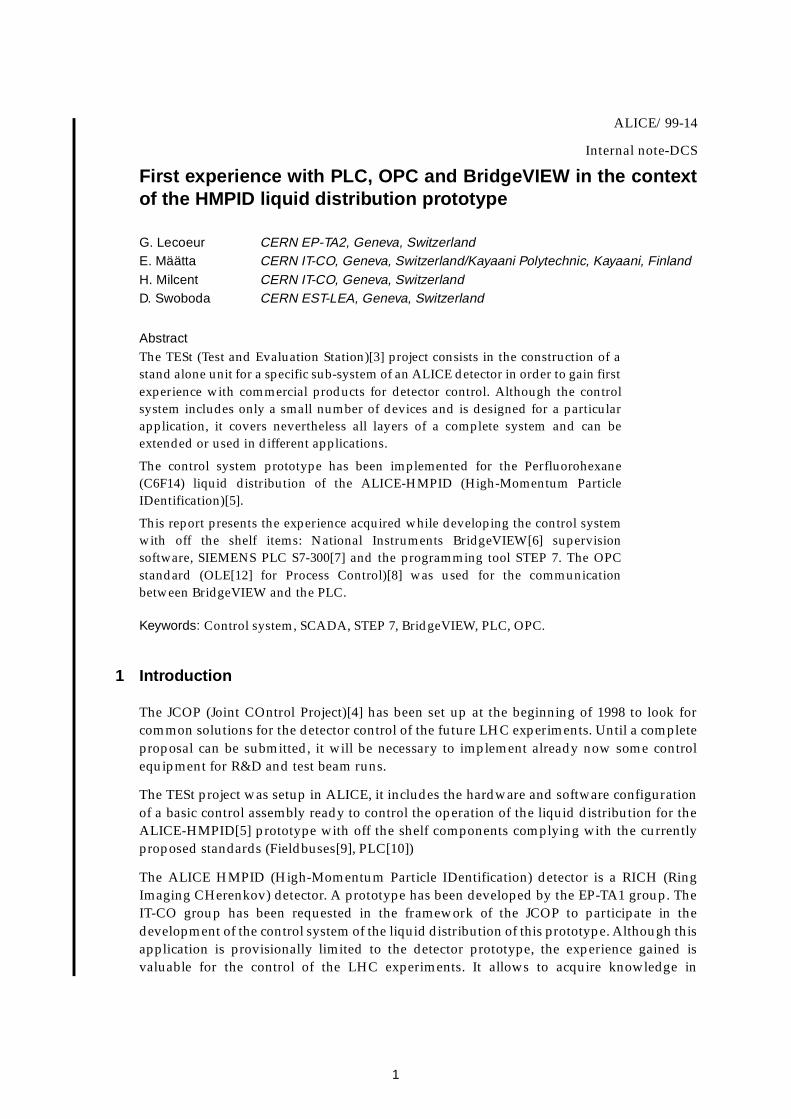
The definition of alarms is attached to tags in BridgeVIEW. Four thresholds and a bad statealarm can be defined for every tag. Alarms are generated by the Engine when a tag value isoutside the thresholds. Thresholds are absolute values and have a priority level whichcharacterizes the severity of an alarm state.
Alarms are configured with the tag configuration editor (Figure 6)
6
Figure 6: The alarm configuration editor
An alarm is acknowledged either manually or automatically when the tag value goes backto normal.
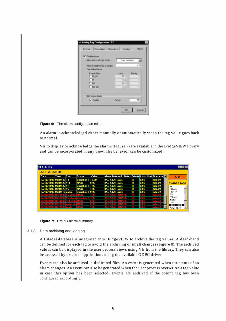
VIs to display or acknowledge the alarms (Figure 7) are available in the BridgeVIEW libraryand can be incorporated in any view. The behavior can be customized.
Figure 7: HMPID alarm summary.
3.1.3 Data archiving and logging
A Citadel database is integrated into BridgeVIEW to archive the tag values. A dead-bandcan be defined for each tag to avoid the archiving of small changes (Figure 8). The archivedvalues can be displayed in the user process views using VIs from the library. They can alsobe accessed by external applications using the available ODBC driver.
Events can also be archived in dedicated files. An event is generated when the status of analarm changes. An event can also be generated when the user process overwrites a tag valuein case this option has been selected. Events are archived if the source tag has beenconfigured accordingly.

7
Logged events can be displayed in user process views with the Event History VI from thelibrary. This VI is similar to the Alarm summary VI.
Figure 8: Engine, Archiving and logging setting panel.
Archiving and logging can be globally controlled from a VI or by setting start-uppreferences from the Engine Manager.
3.1.4 Access control
BridgeVIEW allows to protect the operation environment and the process (launching of theEngine, start and stop of archiving, etc.). The protection is based on user privileges whichare granted by the system administrator to each user.
The process is protected by restricting operation and visibility of HMI items.Administrators may define levels (or groups of users) and give each user a level. A level hasa value and a name. The visibility and/or the operation of any HMI item can be restrictedby specifying in the G code the minimum level value required to view and/or operate theitem. Users of the application have to log in when access control is used.
3.1.5 HMI
HMI in BridgeVIEW consists of two parts, the front panel and the block diagram.
The front panel contains the graphical views. The BridgeVIEW objects library includes alarge selection of objects to construct the views (VI). Graphics, Real-time and historicaltrends can also be integrated in the front panel.
A block diagram with the necessary G code to control the behavior is required for eachcontrol panel. A rather large library of VIs covering HMI, mathematics, data analysis,networking, on-line configuration facilities is provided with the G language developmentenvironment.The HMI wizard allows to generate G code automatically. This is provided formost graphical items and creates an item specific behavior. The automatically generatedcode can subsequently be customized by the developer.

8
3.2 PLC
An increasing number of industrial system is now implementing PLCs (ProgrammableLogic Controller) for process control. PLCs are compact computers including all thenecessary hardware interfaces to the process level. They are generally used for automaticcontrol applications (closed loop control, etc.) either stand-alone or networked throughfieldbuses or most recently on industrial ethernet connections.
A PLC includes a power supply, a CPU and input/output modules mounted in a rack.Modules and CPU can be connected through a SIEMENS proprietary backplane bus(Figure 9) or distributed by using a fieldbus such as PROFIBUS[11].
Figure 9: PLC with local input/output module.
The control program for the PLC is set up in a special development environment and thendownloaded to the CPU. A user program is composed of the following items:
• OB: Organization Block. OBs are called by the operating system. Three kinds of OBsexist: OBs executed at the start-up of the CPU; OBs executed under definedconditions or at periodic intervals, OBs executed on interrupts or errors detected bythe CPU. The available OBs are a function of the CPU type. Each OB has a priority andthe highest priority OB is executed before the lowest priority OB. Table 1 shows thedifferent OBs.
• SFC: System Function. This is a function like a system call in the C programminglanguage.
• FC: User Function. It consists of a user supplied function with inputs and outputs butwithout memory block.
• FB: Function Block. This is similar to a FC with a block of memory (DI) associated to it.
• SFB: System Function Block.
• DB: Data Block. This is a memory area containing data of the user program. DBs canbe opened and closed dynamically.
• DI: Instance Data Block. This is a DB associated with a FB. One FB can have multipleDIs.
powersupply CPU input/output modules
S7-300

9
Table 1: Types of OBs and its priority.
The PLC memory is divided in different areas shown in Table 2.
Table 2: Memory area of a PLC.
3.2.1 User program
A user program is composed of OBs edited by the user and downloaded in the CPU. TheOBs call FBs, FCs, SFCs and SFBs. FBs and FCs can call SFBs, SFCs and other FBs and FCs.
Type of interrupt (CPU clock, hard-ware/software interrupts, etc.) OB Priority
main program scan OB1 1
time-of-day interrupt OB10 to OB17 2
time-delay interrupt OB20 to OB23 3 to 6
cyclic interrupt OB30 to OB38 7 to 15
hardware interrupt OB40 to OB47 16 to 23
multicomputing interrupt OB60 25
asynchronous error interrupts OB80 to OB87 26
background cycle OB90 0.29
synchronous error interrupts OB120, OB122 Priority of the OB that caused the error.
memory area description
Process-image input: I The CPU reads the digital input modules and records in this area the values.
Process-image output: Q The CPU sends the values stored in this area to the connected digi-tal output modules.
Bit memory: M Memory storage for interim result used by the user program.
Timer: T Storage area for timers.
Counter: Z Storage area for counters.
Data Block: DB Data Block containing user data for the user program. A DB is like a shared memory.
Data Block: DI Instance Data Block assigned for FBs (Functional Block) or SFBs (System Function Block)
Local (temporary) data: L This area contains the temporary data of the block while the block is being executed.
Peripheral input: PI Direct access to the data of the local or distributed input modules
Peripheral output: PQ Direct access to the data of the local or distributed output modules

10
FBs, FCs and OBs can read and write data in the DBs. FBs can read and write data in DIs(Figure 10). The user program has access to the following CPU memory areas: I, Q, PI, PQ,M, T, DB and Z. There is a set of predefined data types including integer, boolean, etc., it isalso possible to define new data types that can be used as template for creating DB blocks.
Figure 10: User program module organization.
The number of blocks that can be nested and the number of FCs, FBs and DBs depends onthe type of CPU. Figure 11 shows the sequence of a block call within a user program. Theinstructions of the block are executed when it is called by the program. After the executionof the block, the execution of the previously interrupted block that made the call is resumedat the operation following the block call. Before creating a block, it is necessary to create thevariables that are used:
• input and output variables of the block
• static variables which are used in the DI block and preserved after the end ofexecution of the FB
• dynamic variables which are available during the execution of the block and releasedwhen the block is completed.
Figure 11: Calling a block.
SFCDB
FC
FC
SFC
SFB
FC
FBSFB
read/writesystem calluser callO
pera
ting
syst
em
OB
jump toreturn to
FB
DI
Programexecution
Programexecution
Programexecution
Block end
Instruction thatcalls another block
Calling Block(OB, FB or FC)
called block(FB, FC, SFB or SFC)

11
The SIEMENS PLC operates in polling mode with defined execution cycles. Figure 12illustrates the phases of the cyclic program execution:
• the operating system starts the cycle monitoring time.
• the operating system copies the value of the digital input module mounted in theCPU rack to the I-memory area of the CPU.
• the operating system processes the user program (OBs) and executes the instructionscontained in the user program. The user program has to read/write the analog valueof the analog module mounted in the CPU rack and the value of the digital or analogmodules distributed via a fieldbus to/from DB- or M- memory area. The userprogram has read and write access to the I- and Q- memory area.
• the operating system writes the values from the Q- memory area to the digital outputmodules mounted on the CPU rack.
• at the end of the cycle, the operating system executes any tasks that are pending, forexample loading and deleting blocks, receiving or sending data to remote PLC, etc.
• the operating system returns to the start of the cycle and restarts the cycle monitoringtask.
Figure 12: PLC program scan
The cycle time of the CPU is the time to execute the cyclic program and all the programsections resulting from interrupts during the cycle and the time required for systemactivities. For the S7-300 PLC, OB80 is the block called in the case the cycle time is too smallto execute the user program.
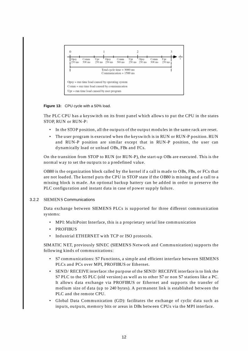
The communication load is the load added by the communication to the cycle and impiedson the run time of the user program. Figure 13 illustrates a worst case example with a cycletime set to 1 sec, a user program with a total execution time equal to 750 msec, 250 msec percycle time for the operating system and a communication load set to 50%. A load set to 50%means that half of each cycle can be used by communication. In this example, the total CPUcycle is tripled. During configuration, the default maximum cycle time and the load can bemodified.
Startup program
start of the cycle time monitoring
read the digital input modulesand update the process image input table (I)
execute the user program (OBs)
write the process image outputtable to the digital output module (Q)
operating system tasks
ma
in p
rog
ram
sca
n
12
Figure 13: CPU cycle with a 50% load.
The PLC CPU has a keyswitch on its front panel which allows to put the CPU in the statesSTOP, RUN or RUN-P:
• In the STOP position, all the outputs of the output modules in the same rack are reset.
• The user program is executed when the keyswitch is in RUN or RUN-P position. RUNand RUN-P position are similar except that in RUN-P position, the user candynamically load or unload OBs, FBs and FCs.
On the transition from STOP to RUN (or RUN-P), the start-up OBs are executed. This is thenormal way to set the outputs to a predefined value.
OB80 is the organization block called by the kernel if a call is made to OBs, FBs, or FCs thatare not loaded. The kernel puts the CPU in STOP state if the OB80 is missing and a call to amissing block is made. An optional backup battery can be added in order to preserve thePLC configuration and instant data in case of power supply failure.
3.2.2 SIEMENS Communications
Data exchange between SIEMENS PLCs is supported for three different communicationsystems:
• MPI: MultiPoint Interface, this is a proprietary serial line communication
• PROFIBUS
• Industrial ETHERNET with TCP or ISO protocols.
SIMATIC NET, previously SINEC (SIEMENS Network and Communication) supports thefollowing kinds of communications:
• S7 communications: S7 Functions, a simple and efficient interface between SIEMENSPLCs and PCs over MPI, PROFIBUS or Ethernet.
• SEND/RECEIVE interface: the purpose of the SEND/RECEIVE interface is to link theS7 PLC to the S5 PLC (old version) as well as to other S7 or non S7 stations like a PC.It allows data exchange via PROFIBUS or Ethernet and supports the transfer ofmedium size of data (up to 240 bytes). A permanent link is established between thePLC and the remote CPU.
• Global Data Communication (GD): facilitates the exchange of cyclic data such asinputs, outputs, memory bits or areas in DBs between CPUs via the MPI interface.
13
Not all the SIEMENS CPUs support all S7 functions. For example a S7 CPU 3xx can onlyinitiate SEND/RECEIVE connection to the remote partners, but it can receive S7communication calls. The number of SEND/RECEIVE link and GD (Global DataCommunication) depends on the CPU type.
The SIEMENS S7 PLC supports multicomputing that is simultaneous and/or synchronizedoperation on different CPUs in the same rack. A maximum of four CPUs can be mounted inthe same rack.
The SAPI-S7 (Simple Application Programmers Interface) is the S7 functions for the PC toexchange data between a PC and a S7 PLC. It is a connection oriented transport protocolwhich provides a virtual channel for the user. The communication consists of the following:
• logon
• connection establishment
• data exchange
• connection termination.
In the PC, using the COML S7 tool, a S7 database has to be created where the name of thevirtual device (VFD), the address of the device (IP number, Ethernet address or PROFIBUSaddress) and the name of the connection are defined.
3.2.3 Development tool set environment
STEP 7 is the development software used to configure and program the S7 PLCs. It is a setof tools for:
• setting up and managing a project
• configuring and assigning parameters to hardware
• configuring communication links
• creating the control programs for the PLC
• downloading and testing the programs in the target system.
STEP 7 includes three languages of the IEC 1131-3 (International ElectrotechnicalCommission’s standard) set:
• LADder logic (LAD). The syntax for the instructions is similar to a relay ladder logicdiagram. Ladder allows to track the power flow between power rails as it passesthrough various contacts, complex elements and output coils (Figure 14).

14
Figure 14: LAD programming.
• STatement List (STL) is similar to machine code. The instructions of a STL programcorrespond to the steps of the program executed by the CPU (Figure 15).
Figure 15: STL programming.
• Function Block Diagram (FBD). The syntax uses logic boxes, like AND, OR fromboolean algebra to represent the logic (Figure 16).

15
Figure 16: FBD programming.
Other programming languages are available as optional packages:
• S7 Structured Control Language (SCL). It contains language constructs similar tothose found in the PASCAL and C programming languages. It can be used incombination with STL, LAD and FBD.
• S7 GRAPH. This is used to program sequential controls. The process sequence isdivided into steps which contain action to control the outputs. The transition fromone step to another one is controlled by switching conditions (Figure 17). An OB orFB written in STL, FBD or LAB calls the sequencer.

16
Figure 17: S7 GRAPH example.
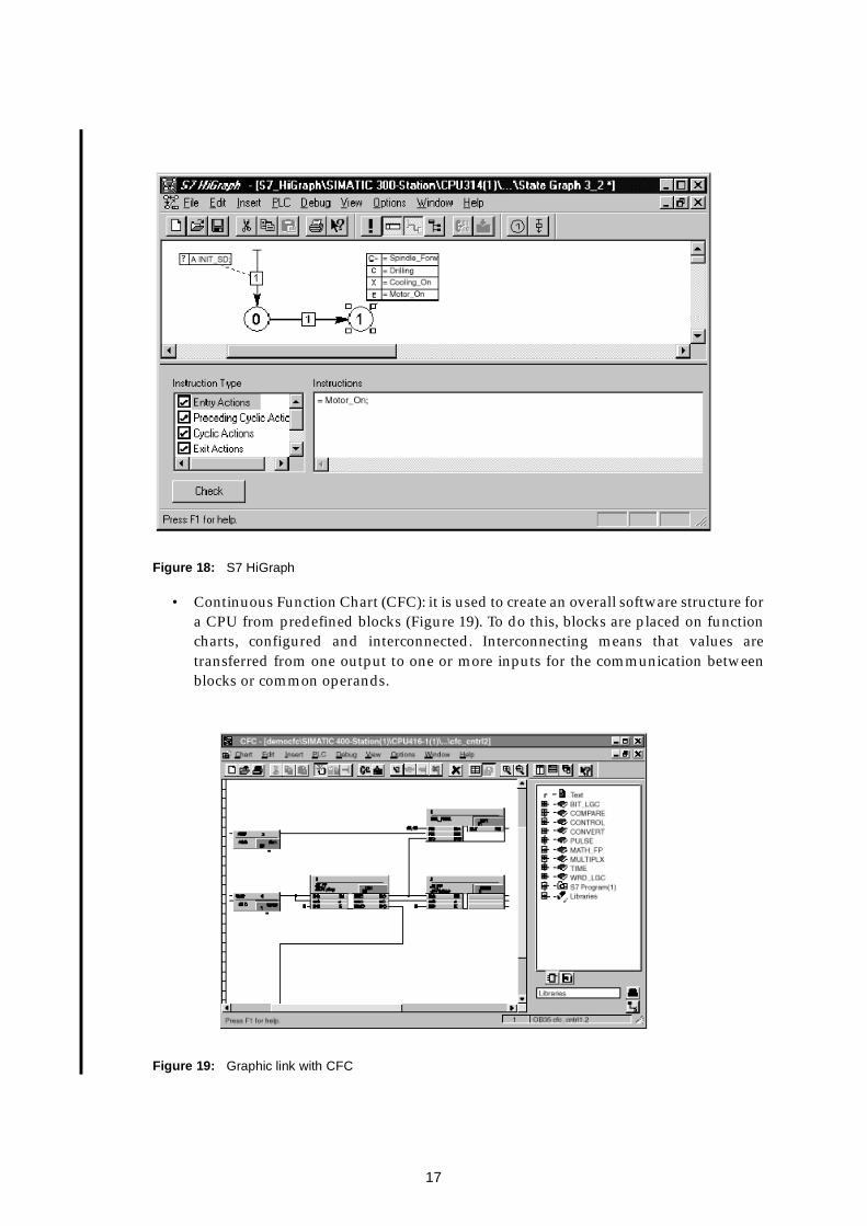
• S7 HiGraph. This is used to describe asynchronous, non-sequential processes in theform of state graphs (Figure 18). Messages can be exchanged between differentgraphs to do synchronization. The graph has to be called by a cyclic OB. The graphcan call FCs, FBs written in STL, LAD, FBD and SCL.
17
Figure 18: S7 HiGraph
• Continuous Function Chart (CFC): it is used to create an overall software structure fora CPU from predefined blocks (Figure 19). To do this, blocks are placed on functioncharts, configured and interconnected. Interconnecting means that values aretransferred from one output to one or more inputs for the communication betweenblocks or common operands.
Figure 19: Graphic link with CFC

18
Library functions like the SEND/RECEIVE interface, or system functions like JUMP,MOVE, etc. are included in STEP 7 and accessible from all the languages.
Projects in STEP 7 represent the sum of all the data and programs within the scope of anautomation task. They are used to store the data and programs in an organized manner. Thedata collected in a project include:
• configuration data for the hardware structure and the parameters of the moduleswhere you drag and drop the desired hardware module (Figure 20)
• configuration data for communication on the networks (Figure 22): Ethernet,PROFIBUS, MPI
• programs for the PLC (Figure 21).
STEP 7 supports two modes: off-line and on-line from which one can use the same tools. Inoff-line one can download the software to the PLC, and in on-line mode, one can upload therunning software from the PLC.
Figure 20: The STEP 7 tool to configure the hardware.

19
Figure 21: Blocks and functions of the HMPID PLC user program.
Figure 22: The STEP 7 tool to configure the networks.
The user program and the PLC configuration can be downloaded with STEP 7 by MPI,PROFIBUS or Ethernet. In the case of Ethernet, the IP number of the card has to be enteredfirst by MPI bus.
A Graphical debugger is available in STEP 7. The variables: inputs, outputs, bit memory,counters, peripheral outputs and elements of DB can be displayed (monitored) and
20
modified. In STL language, the program is debugged via step by step execution and settingbreakpoint or by displaying the content of the registers of the statements. FBD and LADprograms are debugged by showing the signal flow within the network of a block.
The CPU and I/O module diagnostic buffer in which are stored the online warnings orerrors during execution is accessible within STEP 7.
3.3 OPC
OPC is an acronym for OLE for Process Control and is used as a standard interface forcommunication in automation engineering. OLE includes the component model ofMicrosoft. The OPC interface is the specification of a uniform and vendor independentsoftware interface based on OLE. It was developed as an industrial standard by leadingfirms in the field of automation with the support of Microsoft.
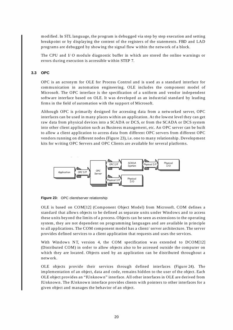
Although OPC is primarily designed for accessing data from a networked server, OPCinterfaces can be used in many places within an application. At the lowest level they can getraw data from physical devices into a SCADA or DCS, or from the SCADA or DCS systeminto other client application such as Business management, etc. An OPC server can be builtto allow a client application to access data from different OPC servers from different OPCvendors running on different nodes (Figure 23), i.e. one to many relationship. Developmentkits for writing OPC Servers and OPC Clients are available for several platforms.
Figure 23: OPC client/server relationship
OLE is based on COM[12] (Component Object Model) from Microsoft. COM defines astandard that allows objects to be defined as separate units under Windows and to accessthese units beyond the limits of a process. Objects can be seen as extensions to the operatingsystem, they are not dependent on programming languages and are available in principleto all applications. The COM component model has a client/server architecture. The serverprovides defined services to a client application that requests and uses the services.
With Windows NT, version 4, the COM specification was extended to DCOM[12](Distributed COM) in order to allow objects also to be accessed outside the computer onwhich they are located. Objects used by an application can be distributed throughout anetwork.
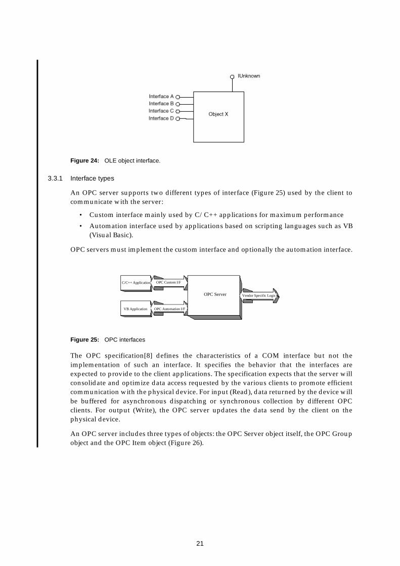
OLE objects provide their services through defined interfaces (Figure 24). Theimplementation of an object, data and code, remains hidden to the user of the object. EachOLE object provides an “IUnknown” interface. All other interfaces in OLE are derived fromIUnknown. The IUnknown interface provides clients with pointers to other interfaces for agiven object and manages the behavior of an object.
21
Figure 24: OLE object interface.
3.3.1 Interface types
An OPC server supports two different types of interface (Figure 25) used by the client tocommunicate with the server:
• Custom interface mainly used by C/C++ applications for maximum performance
• Automation interface used by applications based on scripting languages such as VB(Visual Basic).
OPC servers must implement the custom interface and optionally the automation interface.
Figure 25: OPC interfaces
The OPC specification[8] defines the characteristics of a COM interface but not theimplementation of such an interface. It specifies the behavior that the interfaces areexpected to provide to the client applications. The specification expects that the server willconsolidate and optimize data access requested by the various clients to promote efficientcommunication with the physical device. For input (Read), data returned by the device willbe buffered for asynchronous dispatching or synchronous collection by different OPCclients. For output (Write), the OPC server updates the data send by the client on thephysical device.
An OPC server includes three types of objects: the OPC Server object itself, the OPC Groupobject and the OPC Item object (Figure 26).
C/C++ Application
VB Application
OPC Custom I/F
OPC Automation I/F
OPC Server Vendor Specific Logic

22
Figure 26: OPC object relationship.
3.3.2 OPC Item
The OPC Item object represents the connections to data sources within the server. An OPCitem is not directly accessible as an object by an OPC Client. Therefore, there is no externalinterface defined for an OPC Item object. All access to an OPC Item passes via the OPCGroup object that contains the OPC Item. Associated with each item is a Value, Quality(quality of the value) and Time Stamp attribute. The value is of type VARIANT (OLEterminology): real (VT_R4), signed char (VT_I1), unsigned char (VT_UI1), etc.
3.3.3 OPC Group
An OPC Group object includes the group object information and OPC items. Figure 27 is asummary of the OPC Objects and their interfaces. Some of the interfaces are optionalindicated by [ ].
Figure 27: OPC Group object
OPC GroupOPC Server
OPC Itemrelation 1 to many.
23
The OPC Group has many attributes. Three of them are of particular interest:
• ActiveState
An OPC Server can not only read and write the values of process variables but alsomonitor specific conditions. Monitoring means that the OPC Server checks whetherthe value of the process variable has crossed a deadband (see PercentDeadBand) aftera time interval (see UpdateRate) has elapsed. In which case the value is automaticallysent to the OPC Clients. Each OPC Group and each OPC Item have an ActiveStateattribute. An OPC Client can disable or enable the ActiveState of an OPC item or anOPC Group.
• UpdateRate
The UpdateRate is the interval at which the OPC Server checks the value of an OPCItem that is monitored.
• PercentDeadBand
This deadband applies only to an OPC Item of type analog. The monitored value isonly sent to the client if it has changed by more than the specified percentage of range(minimum and maximum of the value).
3.3.4 OPC Server
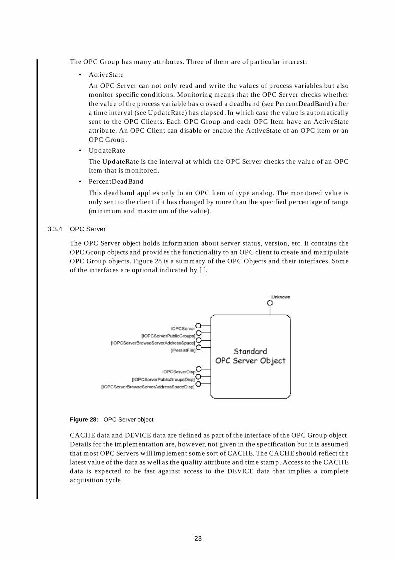
The OPC Server object holds information about server status, version, etc. It contains theOPC Group objects and provides the functionality to an OPC client to create and manipulateOPC Group objects. Figure 28 is a summary of the OPC Objects and their interfaces. Someof the interfaces are optional indicated by [ ].
Figure 28: OPC Server object
CACHE data and DEVICE data are defined as part of the interface of the OPC Group object.Details for the implementation are, however, not given in the specification but it is assumedthat most OPC Servers will implement some sort of CACHE. The CACHE should reflect thelatest value of the data as well as the quality attribute and time stamp. Access to the CACHEdata is expected to be fast against access to the DEVICE data that implies a completeacquisition cycle.

24
Each client application is responsible for storing persistently the relevant clientconfiguration information (OPC Group and OPC item definitions). It is important todistinguish the address space of the server or server configuration like the OPC Item list andsubsets of this space that a particular client may be interested in at a particular time (OPCGroup and OPC Item). The implementation of the server address space will depend on theapplication and could be:
• entirely fixed (e.g. dedicated interface to a particular device)
• configured entirely outside of the OPC environment (e.g. interface to an existingexternal system)
• automatically configured at start-up by a server which can poll the existing system toinquire about installed hardware or interfaces
• automatically configured on the fly by a server based on the names of the data itemsthe client applications are currently requesting.
It is assumed that the server address space is managed within the server.
3.3.5 OPC Client
An OPC Client directs the server to create, manage and delete the OPC Groups. The OPCClient can define one or more OPC Items in each OPC Group in order to access the desireddata and to subscribe to a list of items. Public groups are treated like server defined groupsor used for persistent storage by an OPC server. The concept allows to share configurationdata information across multiple client applications. Public groups can be created whereonly one client application defines the OPC Items and other client applications access theinformation by connecting to the public groups.
Synchronization is the ability of a client to read or write multiple values and attributes in asingle transaction. Serialization is the ability of a client to control the order in which writetransactions are executed.
3.3.6 Access Security
OPC access security is based on the COM/DCOM scheme. There is no security specificcoding inside the DCOM client/server application. Developers and administratorsconfigure the security setting for each component using the NT configuration tooldcomcnfg. The three main parameters are:
• configuration: normally left to the administrator of Windows NT
• launch: defines which user or group of users is allowed to launch the server andretrieve objects
• access: defines which user or group of users is allowed to issue calls on the objectswhen the connection between a client and a server has been established.
No permissions can be defined for OPC Groups or OPC Items for different users within anOPC Server. If the OPC Server computer and the OPC Client computer are not in the samenetwork domain (like the CERN domain for NICE) then users defined in the access andlaunch permission should be declared in the OPC Client computer. DCOM transmits theusername of the calling client application to the remote computer where the correspondingcomponent is running.

25
DCOM maintains a background ping between a client and a server. If a client connection islost Windows NT will detect this within 6 minutes and all the interfaces the client hadrequested from the server will be released.
3.3.7 Integration of OPC in BridgeVIEW
BridgeVIEW can communicate with any server implementing the OPC server interface. Itdetects automatically all OPC Servers installed on the own PC and searches the network forOPC Servers on other computers. Unlike Device Servers, OPC Servers do not storeinformation in the Common Configuration Database but the client needs to read allavailable information about server capabilities and items from the server directly.
Each BridgeVIEW I/O group (Figure 5) created in the Tag Configuration Editor isautomatically mapped to an OPC Group in the OPC Server with the same attributes. TheItem name of the BridgeVIEW tag (Figure 4) is the OPC ItemID (Item IDentificator).
BridgeVIEW uses intensively the Active mechanism (See ActiveState) of OPC. The OPCGroups and OPC Items are saved in the .scf file. It is not possible with the BridgeVIEW OPCClient to request a “Read” on OPC Items.
3.3.8 SIEMENS OPC Server
SIEMENS provides an OPC Server for SIMATIC NET on Windows NT. This server allowssimple access to SIMATIC NET networks for any Windows application that supports thecustom or automation OPC interface. The SIEMENS OPC Server connects to the PLC viaPROFIBUS or Ethernet using the S7 database configured by the COML S7 tool(Section 3.2.2). The ItemID is the identificator of the OPC Item. It is a string with thefollowing structure: [Protocol-ID:<connection-name>]variable-name. The Protocol-ID is DPfor PROFIBUS and S7 for S7 communication over PROFIBUS or Ethernet. The managementof the connection is handled by the OPC Server and is hidden from the user. The connectionname consists of three parts separated by the character “|”:
• the specified name of the S7 connection (e.g.: AL-PLC) defined in the S7 database
• the VFD at which the OPC Server will log on (e.g.: VFD) defined in the S7 database
• the name of the communication processor (e.g.: S7ONLINE when using the SOFTNETpackage for connection via an Ethernet PC card)
The OPC Server allows access to the following data: data blocks (DB), inputs (I), outputs(Q), peripheral inputs (PI), peripheral output (PQ), memory bit (M), timers (T) and counters(C). Three other items are defined for handling the communication and connections:
• &identify(): provides information about the attributes of a device
• &status(): provides the status of the device
• &statepath(connection-name): provides information on the status of the connectionwith the remote device.
OPC Items which are not in the address space of the OPC Server (OPC Item list) aredynamically created when an OPC Client connects to them.
The OPC Server for SIMATIC NET can support simultaneous operation on the DP and S7protocol. The S7 OPC Server can use two different procedures of the S7 protocol to obtainthe value of a process variable. It can poll the values of the variables at a selected interval
26
by sending read requests to the remote partner devices or use the “Remote from PartnerDevice” mode. The partner reports the values of the required variables automatically to theOPC Server at selectable intervals. This reduces the load on the OPC Server. However, thenumber of variables that a remote partner can report is limited by the resources of the PLC.
4 Comments on Hardware and Development tools
The hardware and software environment was entirely new to the team. The followingcomments reflect, therefore, also the experience gained during the learning phase.
4.1 PLC and input/output
PLCs are well adapted to a two level architecture where the control process must beindependent of the supervisory system and where the system (I/O readout, closed loopcontrol, etc.) needs to be reliable and independent from the communication network or aremote computer.
The installation of the PLC and the input/output modules is straight forward and fast.Accessing the IOs does not require any programming. The analog input modules areconfigurable for a wide range of parameters like voltage, current, resistor, pt100, etc. Theconnectors are state of the art technology and are specific for each module type. The valuesat the analog inputs are continuously read and converted to digital. Different filters for noiserejection can be selected with the configuration tools.
The number of input/output modules connected to the CPU bus is limited and depends onCPU type. A maximum of 8 modules can be connected in the same chassis and up to 32 witha rack extension. A wide range of analog readout modules exist. But SIEMENS digitalinput/output modules with a CPU bus connection are restricted to 0-24V or 220V/130V. NoTTL input/output modules are available. Without the optional battery backup the userprogram has to be downloaded after every power off.
Detailed knowledge of the PLC architecture and functionality is required to develop a userprogram. Initially the people involved had no knowledge of SIEMENS PLC S7. Thedocumentation on the PLC and a “quick start” manual are a good help to shorten thelearning time. Only half a day was necessary to configure correctly the input/outputmodules and to read/write digital and analog values. But the documentation on writing auser program, calling FCs or FBs or to use the return value of the calling block, etc. isincomplete and unsatisfactory.
The SIEMENS PLC operates in polling mode with defined execution cycles. The OBs andthe number of blocks (FBs, FCs and DBs) which can be created and the programminglanguages depend on the CPU type but all S7-300 CPUs support STL, LAD and FBD. To readanalog and digital inputs at different scan rates requires complex programming. The digitalinputs are read before every CPU cycle, and the digital outputs are written after every cycle.The analog inputs are not automatically read by the CPU, the user program must access thePI with the corresponding address to get the analog values and PQ to write analog values.Data read through Ethernet or read from PROFIBUS have to be transferred into the CPUmemory through SFC or SFB blocks. The Ethernet connection seems stable but no tests weremade for PLC to PLC communications.

27
4.2 STEP 7, languages and tools
STEP 7 is the SIEMENS development software to configure and program the S7 PLCs. It isan intuitive graphical tool. The FBD, STL and LAD languages are include in the basicversion. Other languages are optional and must be purchased. They are not recommendedfor small S7-300 CPUs. STEP 7 allows to archive and retrieve projects and to create sharedlibraries. The tool is powerful and easy to use. There is also a utility to connect to the PLCand debug the hardware.
Starting to work with STEP 7 is easy and fast. Two weeks only were needed to communicatewith the PLC and understand how it works, use STEP 7 and its tools, write a small programin the FBD language, run it, debug it and test it. A one day initiation from a person withsome experience of STEP 7 helped, however, significantly.
The library provided with the languages are quite extensive. However, documentation onfunctions and on the CPU registers is incomplete. Dynamic checking of the connection typeis performed during the writing of user programs with FBD. Symbolic addressing ofvariables used in any block inside a project can be used instead of direct memory access.Step by step debugging is only available for the STL language. A FBD program can bedebugged by analyzing the signal flow inside the network of a block. Unfortunately, thedebugger shows just the signal flow of the block which is visible in the open window. A“step into” facility when calling a block from another block is missing. However, therun-time diagnostic buffer of the CPU and the I/O modules can be accessed for debugging.
The S7 database in the PC for PC to PLC communication is created with the COML S7 tool.The relevant documentation has, unfortunately, be found to be not very clear.
4.3 OPC
The SIEMENS OPC Server polls the PLC. Fast polling rate and PC CPU load have to bebalanced for best system use. The OPC Items are dynamically created in the Server when anOPC Client requests an “AddItem” for an Item which does not exist. Unfortunately, theycannot be deleted. One solution is to re-start the OPC Server with a new S7 database.
In the HMPID prototype, the OPC Server and the OPC Client run in the same PC. Successfultests were made in the laboratory to access the OPC Server from another computer.
The OPC Server seems to be reliable. It is able to detect and recover from a connection failurewith the PLC. No tests on performance, reliability, etc. were done in the context of thisproject but information is available from the OPC foundation WEB site[8].
4.4 BridgeVIEW
The fundamentals of BridgeVIEW are rather easy to learn, but for more advanced featuresmore detailed documentation would be desirable. The development of a HMI (HumanMachine Interface) is straight forward. A majority of the supervisory facilities are readilyimplemented, but the collection of supplied front panel objects for animation is ratherrestricted. Adjusting the size of objects in the front panel is very tedious especially for smallobjects, e.g. when the size of an object needs to be related to the size of some other object.Moreover, resizing the panel window does not resize the objects as well.

28
The configuration tools (tag configuration editor, server explorer) are user friendly.Exporting and importing configurations is simple and was used to run a copy of theapplication on a remote OPC Server.
During the development, a VI Test Server developed for the TRT Gas prototype was used tosimulate the SIEMENS OPC Server. The BridgeVIEW program could therefore bedeveloped faster without direct link to the PLC.
Wizards, inside BridgeVIEW, allow to create the G programs for the HMI. They are veryhelpful to connect front panel controls or indicators with tags and to create diagrams toopen and close panels. A control, in BridgeVIEW terms, is an object that can receive a valueand can be connected to an input/output tag. The underlying G code periodically checks ifthe value of a control is different from the last value sent to the BridgeVIEW server (OPCClient) of the tag. In this case the new value is sent to the server and written into the RTDBwhen the BridgeVIEW server reads it. If the BridgeVIEW server is unable to send this valueto the hardware, the same value can only be sent again after modifying the wizard code orby setting a different value first and then subsequently the initial one.
The BridgeVIEW panel, i.e. the graphical interface including the control object is executedperiodically even if the value has not changed which is very inefficient since BridgeVIEWneeds to evaluate each time the value of the control and to execute the G code connected tothis control.
BridgeVIEW provides also a wizard for creating the G code for the alarm panel. However,the generated G code had to be edited to include also the acknowledgment of the alarms.
Similarly, tags that are not already initialized when the engine is started do not generatealarms. Therefore, the code generated by the wizard was modified in order to showuninitialized values to the operator.
4.4.1 BridgeVIEW and OPC
The OPC Client of BridgeVIEW is using the Active mechanism of OPC (See ActiveState). Itis not possible to read periodically an OPC Item. In the “OPC DCOM White Paper”[8]available on the OPC foundation web site, it is written that an OPC Client can detect afailure of the OPC Server by periodical calls like ‘IOPCServer->GetStatus()’. BridgeVIEWdoes not implement that protocol and therefore it is unable to detect OPC Server failure. Analarm error status on the tag is only raised, as soon as the client tries to write to an OPC Itemotherwise no alarms are generated. In addition, BridgeVIEW can only connect again to theOPC Server after the engine is re-started.
5 Conclusion
PLCs are a suitable solution where the control process must be independent of thesupervisory system and where the system (I/O readout, closed loop control, etc.) needs tobe reliable and independent from the communication network or a remote computer. Theprogramming tools are intuitive and easy to use.
BridgeVIEW is adequate for the development of supervisory applications for smallprototypes. It is flexible enough to develop the user interface required for the prototypeHMPID liquid distribution.

29
OPC looks promising as a common interface between systems, especially as it allows at alater stage to migrate smoothly to another supervisory system. Whereas somedocumentation exists on the OPC foundation web page[8], more investigation will benecessary to study reliability, performance and general capabilities.
The ALICE-HMPID liquid distribution prototype application has a modular structure thatwill allow expansion to the full HMPID detector. The software at the level of the controlfunctions in the PLC and also the supervisory level has been designed to be adaptable todifferent control strategies and is scalable to larger applications. The system has been testedto the full satisfaction of the users from the point of view of control functionality and theuser interface. Improvements and extensions to the functionality are foreseen and will beimplemented as result of operational experience.
Although the application developed was provisionally limited to a detector prototype, theexperience gained will be valuable for the control of the LHC experiments.
Acronyms
OPC. OLE for Process Control
SCADA. Supervisory Control And Data Acquisition
DCS. Distributed Control System
PLC. Programmable Logic Controller
HMPID. High-Momentum Particle IDentification
RICH. Ring Imaging CHerenkov
References
1 ALICE URL:http://www.cern.ch/ALICE/
2 ALICE DAQ, DCShttp://www.cern.ch/ALICE/Projects/Detector_Control_System/http://aldwww.cern.ch/
3 Test and Evaluation Station (TESt), A control system for the ALICE-HMPID liquiddistribution prototypeALICE/99-13 Internal note-DCS
4 JCOP home page URL:http://itcowww.cern.ch/jcop/
5 ALICE HMPID TDR URL:http://www.cern.ch/ALICE/TDR/HMPID/
6 National Instrument home page URL:http://www.natinst.com/
7 SIEMENS:http://www.siemens.de/en/
8 OPC foundation:http://www.opcfoundation.org/http://www.opcfoundation.org/opc_public_tech.htm
9 Fieldbuses recommendation

30
http://itcowww.cern.ch/fieldbus/report1.html
10 PLC recommendationprivate communication
11 PROFIBUS:http://www.profibus.com/
12 OLE-COM-DCOM:http://www.microsoft.com/activex/default.asp
Acknowledgment
We would like to thank F. Michaud (IT/CO), P. Baehler (I/CO) who helped us withBridgeVIEW, R. Barillere (IT/CO) for his useful comments on BridgeVIEW and J.R. Sendondel Rio (IT/CO) for the help and advice on OPC.