first issue:an exciting new electronics magazine! icd … · 2019-07-17 · first issue:an exciting...
TRANSCRIPT

FIRST ISSUE:AN EXCITING NEW ELECTRONICS MAGAZINE! ICD 08559
RN ELECTRONICS
OCTOBER 1984 $1.95
THE MAGAZINE FOR ELECTRONICS & COMPUTER ENTHUSIASTS
* Easy Steps to Add Electronic Ignition Systems to Cars & Boats * Heath's New " Hero Jr. " * Controlling a VCR with a Flashlight * Getting Started in the World of Hobbyist Electronics * How Far Did Apple Ilc Computers Fall from the Tree? * Lower Fuel Bills with Simple Furnace
Add -On * Coil Tester Detects Shorted Turns * Epson's New Pocket Color TV * Latest News in the Electronics Field
o
74820 08559
Plus: Testing Luxman's Compact -Disc Player /JVC's New Stereo HiFi VCR /Star Micronics's "Powertype" Computer Printer /Heath's Component Tester Electronic Experimenting with Forrest Mims
Technical Book Reviews International Shortwave Listings
www.americanradiohistory.com
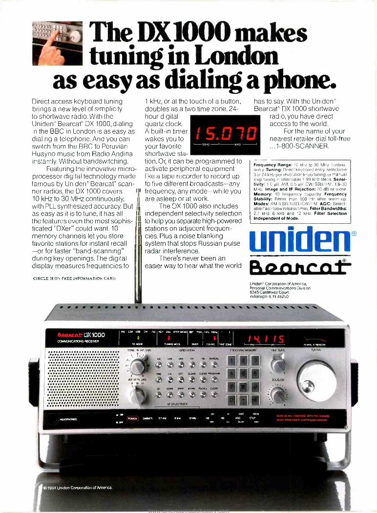
The DX1000 makes tuning in London
as easy as dialing a phone. Direct access keyboard tuning brings a new level of simplicity to shortwave radio. With the Uniden" Bearcat" DX 1000, dialing in the BBC in London is as easy as dialing a telephone. And you can switch from the BBC to Peruvian Huayno music from Radio Andina instantly. Without bandswitching.
Featuring the innovative micro- processor digital technology made famous by Uniden' Bearcat" scan- ner radios, the DX 1000 covers j
10 kHz to 30 MHz continuously, with PLL synthesized accuracy. But as easy as it is to tune, it has all the features even the most sophis- ticated "DXer" could want. 10 memory channels let you store favorite stations for instant recall -or for faster "band- scanning" during key openings.The digital display measures frequencies to
CIRCLE 28 ON FREE INFORMATION CARD
1 kHz, or at the touch of a button, doubles as a two time zone, 24- hour digital quartz clock. A built -in timer wakes you to your favorite shortwave sta- tion. Or, it can be programmed to activate peripheral equipment like a tape recorder to record up to five different broadcasts -any frequency, any mode -while you are asleep or at work.
The DX 1000 also includes independent selectivity selection to help you separate high -powered stations on adjacent frequen- cies. Plus a noise blanking system that stops Russian pulse radar interference.
There's never been an easier way to hear what the world
has to say. With the Uniden Bearcat" DX 1000 shortwave
radio, you have direct access to the world.
For the name of your nearest retailer dial toll -free ...1- 800 -SCANNER.
Frequency Range: 10 kHz to 30 MHz continu- ously. Tuning: Direct keyboard entry, selectable 3 or 24 kHz per revolution knob tuning, or manual step tuning in selectable 1 -99 kHz steps. Sensi- tivity: 1.0 NV AM, 0.5 pV CW /SSB /FM. 1.6 -30 MHz. Image and IF Rejection: 70 dB or more Memory: 10 frequency capacity. Frequency Stability: Better than 100 Hz after warm -up. Modes: AM /LSB /USB /CW /FM. AGC: Select- able Fast /Slow release times. Filter Bandwidths: 2.7 kHz, 6 kHz and 12 kHz. Filter Selection Independent of Mode.
unideno Bacutaar Uniden" Corporation of America, Personal Communications Division 6345 Castleway Court, Indianapolis, IN 46250
DX KW COMMON CATONS RECEIVER
1.1111111111111111 11 111.1.1.111.1..11
11011111 111.11.1.1..11.111 O 4100111..........1...1.1. a
......1.1e....... ::::.:::ï:....e ............ .. 11.0000.11000110018100001111 O 110..04.00...1.10000000...0. 111111..0.00011111101118110. 1 .......................... 00....11.00.....1.001..1..1. 111..1.1111..1.1..1.11.11/1 . 011.1001111101110141010..... 11.0010001.0.100.111.101100 1101100.4.00101111110001.111 100.0100011.1111101011011.1 111100111.100110001100010011 1111111111.1.1.11...1111..1 111.1111..111..111.11.1111./ 111011110101010010118101111 11/1111.11/.1111.11111..111.
AM LSB uSB CW
A
RA MODE
TONE --AFOAR
FM KE V M, STEP MEMO
TUING MODE
SE- TOM
WER
OPERATIW
1"Mi 188Mi
Y IRS WS Ct RV 4'
IF SELECT/RV
2
14,115 _. PROGRAM/MEMORY
-_.
®tt 1 '1 1111Cl111
-SOUELCH
I('B{1::E.t-I r
1III RrtAIE CIIM :
FINE
SIGNK SIRENSTM
1984 Uniden Corporation of America.
www.americanradiohistory.com
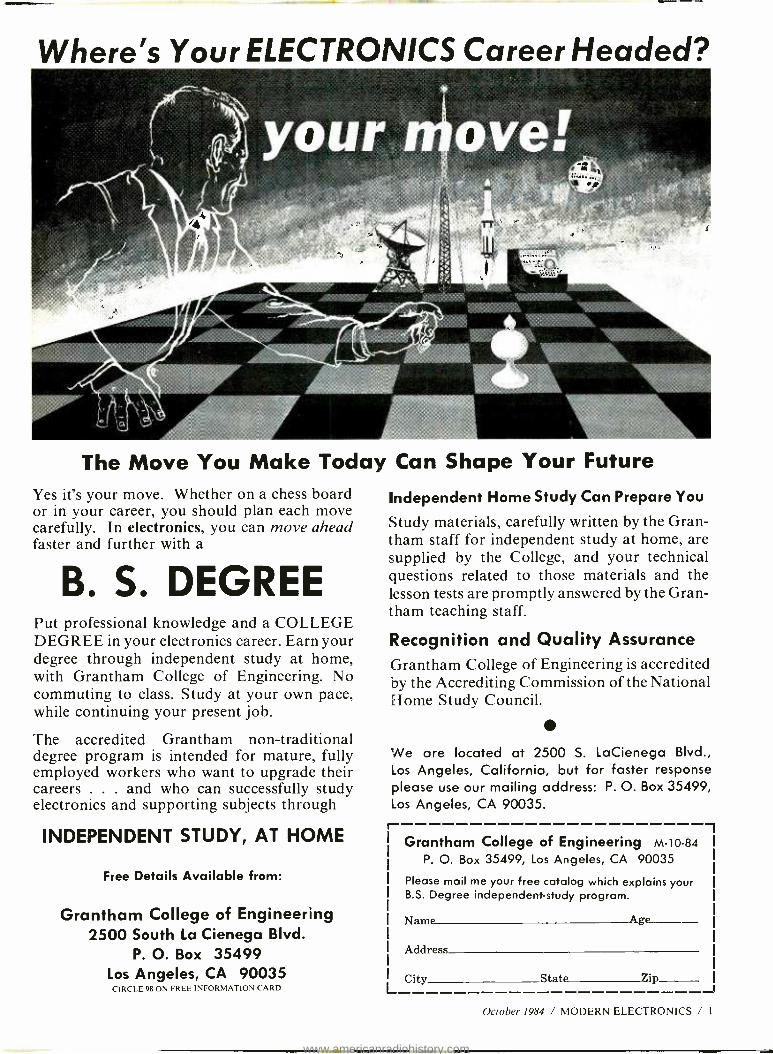
Where's Your ELECTRONICS Career Headed?
The Move You Make Today Can Shape Your Future Yes it's your move. Whether on a chess board or in your career, you should plan each move carefully. In electronics, you can move ahead faster and further with a
B. S. DEGREE Put professional knowledge and a COLLEGE DEGREE in your electronics career. Earn your degree through independent study at home, with Grantham College of Engineering. No commuting to class. Study at your own pace, while continuing your present job.
The accredited Grantham non -traditional degree program is intended for mature, fully employed workers who want to upgrade their careers . . . and who can successfully study electronics and supporting subjects through
INDEPENDENT STUDY, AT HOME
Independent Home Study Can Prepare You
Study materials, carefully written by the Gran- tham staff for independent study at home, are supplied by the College, and your technical questions related to those materials and the lesson tests are promptly answered by the Gran- tham teaching staff.
Recognition and Quality Assurance Grantham College of Engineering is accredited by the Accrediting Commission of the National Home Study Council.
We are located at 2500 S. LaCienega Blvd., Los Angeles, California, but for faster response please use our mailing address: P. O. Box 35499, Los Angeles, CA 90035.
r Grantham College of Engineering M -10 -84
Free Details Available from: P. 0. Box 35499, Los Angeles, CA 90035
Please mail me your free catalog which explains your B.S. Degree independent -study program.
Grantham College of Engineering Name Age
Address 2500 South La Cienega Blvd.
P. O. Box 35499 Los Angeles, CA 90035 City State Zip CIRCLE 98 ON FREE INFORMATION CARD
October 1984 / MODERN ELECTRONICS / 1
www.americanradiohistory.com
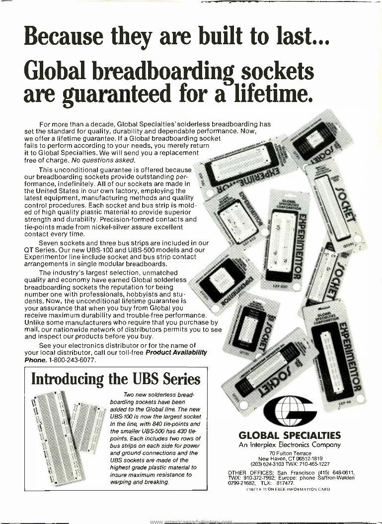
Because they are built to last...
Global breadboarding sockets are guaranteed for a lifetime.
For more than a decade, Global Specialties'solderless breadboarding has set the standard for quality, durability and dependable performance. Now, we offer a lifetime guarantee. If a Global breadboarding socket fails to perform according to your needs, you merely return it to Global Specialties. We will send you a replacement free of charge. No questions asked.
This unconditional guarantee is offered because our breadboarding sockets provide outstanding per- formance, indefinitely. All of our sockets are made in the United States in our own factory, employing the latest equipment, manufacturing methods and quality control procedures. Each socket and bus strip is mold- ed of high quality plastic material to provide superior strength and durability. Precision -formed contacts and tie -points made from nickel -silver assure excellent contact every time.
Seven sockets and three bus strips are included in our QT Series. Our new UBS -100 and UBS -500 models and our Experimentor line include socket and bus strip contact arrangements in single modular breadboards.
The industry's largest selection, unmatched quality and economy have earned Global solderless breadboarding sockets the reputation for being number one with professionals, hobbyists and stu- dents. Now, the unconditional lifetime guarantee is your assurance that when you buy from Global you receive maximum durability and trouble -free performance. Unlike some manufacturers who require that you purchase by mail, our nationwide network of distributors permits you to see and inspect our products before you buy.
See your electronics distributor or for the name of your local distributor, call our toll -free Product Availability Phone. 1-800-243-6077.
Introducing the UBS Series Two new solderless bread-
boarding sockets have been added to the Global line. The new UBS -100 is now the largest socket in the line with 840 tie -points and the smaller UBS -500 has 430 tie - points. Each includes two rows of bus strips on each side for power and ground connections and the UBS sockets are made of the highest grade plastic material to insure maximum resistance to warping and breaking.
GLOBAL SPECIALTIES An Interplex Electronics Company
70 Fulton Terrace New Haven, CT 06512 -1819
(203) 624 -3103 TWX: 710 -465 -1227
OTHER OFFICES: San Francisco (415) 648 -0611, TWX: 910 -372 -7992; Europe: phone Saffron- Walden 0799 -21682, TLX: 817477.
CIRCLE 35 ON FREE INFORMATION CARD
www.americanradiohistory.com

EDITORIAL STAFF Art Salsberg
Editor -in -Chief
Alexander W. Burawa Managing Editor
Dorothy Kehrwieder Production Manager
Elizabeth Ryan Art Director
Pat Le Blanc Phototypographer
Hal Keith Illustrator
Larry Mulvehill Photographer
Leonard Feldman Glenn Hauser
Forrest Mims III Stan Prentiss
Charles Rubenstein Contributing Editors
BUSINESS STAFF Richard A. Ross
Publisher Art Salsberg
Associate Publisher Dorothy Kehrwieder
General Manager Anthony C. Sparacino Newsstand Sales Director
Arlene Caggiano Accounting
Cheryl Chomicki Subscriber Services
SALES OFFICES Modern Electronics 76 North Broadway Hicksville, NY 11801
(516) 681-2976
Eastern Advertising Representative Paul McGinnis Company
60 East 42nd Street New York, NY 10017
(212) 490-1021
Western Advertising Representative JE Publishers Representatives
6855 Santa Monica Blvd., Suite 200 Los Angeles, CA 90038
(213) 467-2266 Jay Eisenberg, Director
San Francisco: (415) 864 -3252 Denver: (303) 595 -4331
Offices: 76 North Broadway, Hicksville, NY 11801. Tel- ephone: (516) 681 -2976. Modern Electronics (ISSN 0748- 9889) is published monthly by Modern Electronics, Inc. Application to mail at second class rates pending at Hicksville, NY and other points. Subscription prices (payable in US Dollars only): Domestic - one year $ 16.97, two years $31.00, three years $45.00; Canada /Mexico -
one year $19.00, two years $35.00, three years $51.00; Foreign - one year $21.00, two years $39.00, three years $57.00. Foreign Air Mail - one year $74.00, two years $145.00, three years $216.00. Entire contents copyright 1984 by Modern Electronics, Inc. Modern Electronics or Modern Electronics, Inc. as- sumes no responsibility for unsolicited manuscripts. Al- low six weeks for delivery of first issue and for change of address. Printed in the United States of America. Postmaster: Please send change of address notice to Modern Electronics, Inc., 76 North Broadway, Hicks- ville, NY 11801.
11111111/MODERN ,1Cs THE MAGAZINE FOR ELECTRONICS B COMPUTER ENTHUSIASTS
OCTOBER 1984
72
so
.e2 47K
J Te /8
6
'2
7
.P3
it 4 7X
/ 017r
VOLUME 1, NUMBER 1
FEATURES 18 Electronic Ignition
Aftermarket electronic ignition systems for automobiles. By Ron Cogan
28 Does the Apple IIc Computer Fall Far From The Tree? Comparing the new Apple "transportable" with the Apple IIe. By Charles Rubenstein
34 A New Era of Go- Anywhere Color TV Epson's novel, pocketable color TV receiver By Alexander W. Burawa
44 How To Get Started in Electronics, Part I Fundamentals of electronics theory By Forrest Mims III
54 The Versatile 555 IC How it works; how to use it. By Duane M. Perkins
64 Will the Real "Father of Personal Computers" Please Stand Up An interview with H. Edward Roberts, who developed the Altair computer. By Art Salsberg
68 "I Am Hero Jr., Your Personal Robot" The Heath Company's new robot product By Alexander W. Burawa
72 Heating Costs Too High? Try a Fuel Miser Project for reducing gas or oil furnace operating costs. By Anthony J. Caristi
76 A Universal Coil Tester Project details plans for a useful instrument By TJ Byers
80 VCR Wireless Remote Pause Switch Project for converting a wired remote videocassette recorder to wireless. By Rich Vettel
PRODUCT EVALUATIONS 10 Luxman DX -103 Compact -Disc Player
Deluxe A CD record player with bells and whistles. By Len Feldman
11 JVC VHS Hi -Fi Videocassette Recorder A new VHS VCR with hi -fi audio provisions. By Len Feldman
12 Heath IT -2232 Component Tracer Heath's new component tester kit By Alexander W. Burawa
16 Star Micronics "PowerType" Daisywheel Printer Low -cost letter -quality printer By Fred Blechman
DEPARTMENTS 4 Editorial
A Warm Welcome. By Art Salsberg
6 Modern Electronics News 9 New Products
86 Electronics Notebook How Lightwaves are Changing Communications. By Forrest Mims III
90 Communications 50 Countries for Shortwave. By Glenn Hauser
102 Books and Literature 108 Advertisers Index
October 1984 / MODERN ELECTRONICS / 3
www.americanradiohistory.com
LETTERS A New Electronics Magazine
Just learned you are starting a new elec- tronics magazine, a real need since Popu- lar Electronics became just another com- puter magazine. Really do miss a good nuts and bolts electronics publication. Please direct this to your circulation de- partment so that I can subscribe. I'm a ham radio operator, but have two and one -half computers (one is in the building stage), and do a lot of electronic construc- tion. I hope you will balance coverage be- tween computers and electronics. There are a "zillion" computer magazine out now, and I subscribe to close to a dozen. David D. Holtz Eastman Kodak Company Rochester, IVY
I just read about your new Modern Electronics and I'm excited about it. Af- ter subscribing to Popular Electronics for the past 25 years, I was very dismayed over the switch to a 100% computer magazine. F. Hoffart Santa Clara, CA
Delighted to hear about launching of Modern Electronics. There's a great need for a replacement for the Popular Elec- tronics of old. Many of us feel left out in the cold. Harold Wright Ontario, Canada
The following letters are representative of reader responses that came across my desk when Popular Electronics changed its editorial thrust.
What are you doing? I found your mag- azine very enjoyable in the past, but you dropped all the projects. Now you're just another product magazine. Anoy Prigge Bromalea, Ontario, Canada
I mainly subscribed for overall cover- age of the electronics field. The articles I
liked best, such as those by Forrest Mims, were dropped. Cancel my subscription. Ricky Huegel Allentown, PA
Thanks for many years of enjoyable reading. I'm not renewing my subscrip- tion because of your new magazine for- mat. I enjoyed the construction articles you used to have. I haven't built many, but seeing other peoples' designs is always informative. Robert Blick Fort Bragg, CA
IIi// EDITORIA L A Warm Welcome
Welcome to Volume 1, Number 1, the very first issue of our new monthly maga- zine, Modern Electronics. As you digest its contents, you'll observe that it is a veritable one -stop source of "hard" in- formation for electronics and computer enthusiasts: stereo, video, computers, hobbyist electronics, communications, servicing, technology, and electronic ex- perimenting. All in one neat package.
Directed to enthusiasts like yourselves, who savor learning more about the latest developments in electronics and comput- er hardware, Modern Electronics shows you what's new in the world of electron- ics /computers, how this equipment works, how to use them, and construction plans for useful electronic devices.
Many of you probably know of me from my decade -long stewardship of Popular Elec- tronics magazine, which changed its name and editorial philosophy last year to distance it- self from active electronics enthusiasts who move fluidly across electronics and computer product areas. In a sense, then, Modern Electronics is the successor to the original concept of Popular Electronics, providing a virtual continuum in catering to the needs of technic- ally oriented people who thirst for ongoing knowledge about all the innovative happen- ings in the electronics /computer field, stressing what's happening inside the enclosure and presenting this information in an inviting manner.
We've gathered a galaxy of fine writers to cover the myriad fields that make up "elec- tronics." Forrest Mims III, for example, the leading star in electronic experimenting to- day, will regularly illustrate how to work with a variety of devices and circuits, every one of which he has personally built and checked out. His "Electronics Notebook" column will explore this area with you every month. Stan Prentiss will cover the video waterfront, starting next month. From videocassette recorders to satellite TV systems, his biting com- ments will give you new perspectives in every area of "sight" equipment. Len Feldman, a distinguished audio authority and author, will do the same for audio, while Dr. Charles Rubenstein will dissect computers, as will other computer specialists. And a host of leading electronics authors will add their creative efforts to the battery of exciting articles we will continually present.
Who reads Modern Electronics? Past experience indicates that the typical reader will be male with a median age in the mid -thirties. More than two -thirds can be expected to be professional, managerial, business owner, or technical people, most of them allied in one manner or another to the electronics field. Largely college trained, our readers will likely be intelligent, inquisitive, elitist, and have a special affinity for technical matters and high - tech products of every sort. About 15% of our readers will probably be college or high - school teachers of engineering, science, computers, or math and students in these areas.
As a participating type of reader, many of you would like to write for us we know. To do so, you should send a brief summary of your proposed article and your background to- gether with a stamped /self- addressed envelope. Construction project proposals also should be accompanied by a schematic or block diagram and the approximate builder's cost. Payment is made upon acceptance.
We'll be starting a "Reader Assistance" department to help you locate hard -to -find parts, equipment, and schematics, and to list used equipment you'd like to sell. This will be published once on a first in, first listed basis at no charge.
Naturally, your letters will be received with great pleasure. Interestingly, our first issue has a "Letters" department, below. They came from people who learned that we were starting Modern Electronics and from readers who objected to the elimination of electron- ics in the magazine I formerly edited.
As part of the publishing group that produces CQ Amateur Radio and Popular Com- munications magazines, Modern Electronics has the underpinning support that's usually necessary to produce a high -circulation magazine today. So we're here to stay.
Looking forward to your comments and suggestions as we grow. n /MT
4 / MODERN ELECTRONICS / October 1984
www.americanradiohistory.com

RCA is one source for the best of everything in servicing parts and components - to give you a better payoff with less effort.
No need to run from supplier to supplier. Your RCA Distributor has all the replacement prod- ucts you need. RCA exact replacement parts. VCR parts for all makes of video tape recorders. Receiving tubes. Picture tubes. SK /MRO replace- ment semiconductors. Video accessories. Indus- trial tubes. And all the rest. All bearing the RCA pedigree.
Nobody offers more or better products for electronics servicing and repair than RCA.
With everything you need from a single, dependable source, there's a lot less paperwork for you. There's the assurance of RCA quality all the way. And you get the extra profits that come with simplified operations.
To make your repair work even easier, RCA offers the latest cross- reference guides, service manuals, directories, catalogs, and other valu- able literature.
What's more, you're backed by RCA's top brand recognition and solid promotional programs.
Contact your RCA Parts, Tubes and SK /MRO Distributor. Or write RCA Distributor and Special Products Division, 2000 Clements Bridge Road, Deptford, N.J. 08096, Attn: Sales Promotion Services. Please specify the products of interest to you.
RC,'
CIRCLE 45 ON FREE INFORMATION CARD
October 1984 / MODERN ELECTRONICS / 5
www.americanradiohistory.com
11111/ MODERN ELECTRONICS NEWS IIIIN
HELPING SOFTWARE DEVELOPERS. Apple Computer introduces a new "school" for computer software (and hardware) developers. It's called "MacCollege," a three -day session for developers who want to put finishing touches on their Macintosh -computer products. Classes held at Apple's Macintosh Software Mill in Cupertino, CA are open 24 -hours a day. Features direct contact with Mac software engineers, and covers subjects such as user interface, program design, and real -time debugging. Call (408) 973 -4897 to register. Sessions end mid- November.
ELECTRONIC DROPOUTS. Giving up is never easy. Among the recent dropouts in the electronics /computer business is RCA's benching of its videodisk player, launched in March 1981. The company sold "only" about 500,000 units in three years, racking up a
$580 -million loss. That's about $1,100 per player, which started life at a suggested retail of $499 and dropped down to $199. . . .
The Postal Service signed off, too, running away from its computer -mail business, E -COM. First -year mail projection of 20 million was in reality only 7 million. What could one expect when a minimum of 200 pieces with different addresses were required, and communication links to other cities could not be established? . . . .The Direct Broadcasting System (DBS) satellite -to -home TV transmissions took some knocks when CBS decided to drop out of the embryonic business. Included in its early plans was a high - definition video channel. Western Union killed its DBS plans on the heels of CBS's announcement, while RCA cut back its invest- ment. Will we ever see those anticipated 21 -ft. antenna dishes marring the skyline? . . . .Pac -Man notwithstanding, Warner Communications "sold" its Atari unit to former Commodore Computer chief exec Jack Tramiel, who recently separated from Commodore. Interestingly, it was Tramiel who led computer price -cutting at Commodore that induced Atari to follow suit, that appears to have been Atari's downfall, that. . .oh, well.
COMPUTER HEALTH INSURANCE. More and more insurance companies are excepting computers from fire /theft policies, just as they generally do now with stereo and VCR's. For protection, you'll need a separate policy. Industry has a similiar problem- - computer- controlled equipment such as robots are not covered by most machinery insurance policies. So Kemper Insurance has stepped in with a machinery repair and lost -time protection policy for such "iron- collar" workers.
COMPUTER SEXISM. With the drive to pronounce women equal to men, it's interesting to observe that a software company's startup premise is that there are no uncomplicated programs written especially for women. Neon Software, Middletown, CN intends to fill this gap, though, with its "Women's Ware" line for the IBM PC and PCjr, starting with a bevy of programs from BUDGET to CALENDAR to CHECKBOOK.
NEW AM -RADIO BAND CHURNING. The National Association of Broad- casters is pressing the FCC for utilization of the unused 1605 to 1705 -kHz band for AM broadcast use.
6 / MODERN ELECTRONICS / October 1984
www.americanradiohistory.com
A NATIONWIDE PAGING SERVICE. To speed up introducing a nation- wide wireless paging system, the FCC plans to use a lottery to select three network organizers from among the companies respond - to its invitation to construct such a system. Satellite or phone facilities will be used to link local paging companies around the country. With this system in place, which applicants had to pledge would be constructed within two years, a Californian business- person travelling in New York could be "beeped" there any time and place.
BETTING ON CD PLAYERS. Audio companies and dealers feel that the sales success of CD players will grow markedly. Prices are still too high, even though dramatic reductions have been made to as low as $300. Furthermore, the catalog of CD records is still rather skimpy, and Compact Discs don't come cheap (about twice the price of vinyl LP records). Nonetheless, more audio companies have a CD player in their line than ever. They're moving into automobiles, too, with Sony showing two models and Mitsubishi and Fujitsu Ten promising them. Sharp Electronics demonstrated an impressive junior -size "jukebox" that selects from among 100 Compact Discs. About 100,000 CD players have been reportedly sold so far, which is some distance away from being a mass -market product.
SMARTER WRISTWATCHES. Both Casio and Seiko introduced real smart wristwatches at a recent electronics tradeshow. Casio's is a data -bank watch that stores 50 information elements with up to six letters and 12 numbers each. Seiko's is an honest - to- goodness wristwatch terminal. The terminal part can hold up to 80 pages of data with 24 characters each page. Notes such as phone numbers can be entered into the terminal and displayed on command.
CARTOONS FOR COCO. A new program for Radio Shack's TRS -80 Color Computer, "The Animator" from Triad Pictures Corp., Sequim, WA, is said to turn COCO into a Hollywood cartoon studio. The three - cassette $35 package comes with a library of character positions, sample sequences, sound effects, and a course in the art of animation. Positions can be cycled and recycled to give the illusion of motion. The frame rate is reportedly about equal to an average "Bugs Bunny" -type cartoon, and yields a smooth pro- fessional look.
SHOOT LIKE A PRO. Sony is offering a new 44- minute Beta- format videocassette titled, "Home Video: Shoot like a Pro." The cassette, which includes an instruction booklet, illustrates how to make good sound recordings, sequencing of shots to tell a story, and how to incorporate camera movement into video shoots. $29.25. Sony trumpets that Betamax BCR owners now have more than 6,000 prerecorded software titles available for their use, with more than 450 Beta HiFi titles. VHS prerecordings have a lot of catching up to do in this area, though some 70% of VCR machines sold have been VHS types.
October 19&4 / MODERN ELECTRONICS / 7
www.americanradiohistory.com

Willi!! NEW PRODUCTS /111111
A Talking Wristwatch If you're accustomed to "read-
ing" the time from your wristwatch, maybe it's time you had a change of pace and bought a watch that tells you the time. That's just what the Sa- toki Talking Watch from Z.I. Talk- ing Technologies is designed to do. Just touch a button and the watch an- nounces the time in a synthesized voice. If you prefer to be alerted to the time automatically, the watch can be programmed with interval voice alerts, with a final "please hurry up" signal. But if you can't break the reading habit or need more informa- tion than just the time, the watch has a conventional LCD panel that dis- plays time in hours, minutes and sec- onds; day and date; and elapsed -time in its stopwatch function.
The watch is programmed in the standard 12 -hour format, with AM and PM voice and visual indication. A built -in alarm function sounds a monotone chime and features a snooze function (with buzzer) with
5- and /or 10- minute intervals. The watch is available in black, beige, and khaki colors. $59.95. Address: Z.I. Talking Technologies, 8619 Reseda Blvd., Northridge, CA 91324.
CD Player for Cars Now you can have all the advan-
tages of the home CD (Compact Disc) player in your car with Sony's Model CDX -5 CD player. Designed to fit into the dashboard slot in DIN - size cars, this ruggedized player's mechanism is made to provide reli- able operation even in the extreme environments inside the typical car. It is claimed to deliver the full mea- sure of performance, including a 90 -dB dynamic range, 0.007% THD, and flat frequency response across the entire audio spectrum.
Automatic disc loading and feath- er -touch controls make the player easy to use. Featured are an Auto- matic Music Sensor (AMS) button for skipping directly from selection to selection in either direction; Music Scan that runs through the entire disc in either direction at 10 times normal speed and produced normal -pitched sound at reduced volume; and sepa- rate repeat modes for any individual track and the entire disc. A fluores- cent display keeps track of either track number or elapsed time.
Sony also offers the Model CDX - R7, which teams a CD player with an
AM /FM- stereo tuner, all in the same size package as the CDX -5.
CIRCLE NO. 102 ON FREE INFORMATION CARD
PCjr Expansion Card Microsoft has a hardware option
for PCjr owners who wish to make their computers more compatible with the existing base of software. Called the PCjr Booster with Mouse, it adds 128K of RAM to the memory in the computer as well as mouse con- trol to programs. With the card in- stalled, the PCjr can run larger, more sophisticated programs, including Microsoft's World, Lotus 1 -2 -3, and Microsoft FORTRAN and Pascal. As a bonus, the card is said to double the speed of programs that require 128K or less of memory. A battery- backed clock /calendar is also included.
Software supplied with the PCjr Booster with Mouse includes a mouse driver and Mouse Menu, Pi- ano, Life, Doodle, RAMDrive, Clock /Calendar, Example Configu- ration Files, and JBASIC. The last is
a software enhancement for the Mi- crosoft BASIC cartridge sold for the PCjr. With the mouse, users have the option of developing and customiz- ing menus to fit individual needs, rather than having to adapt to the predefined sequences of each appli- cation program. $295 without RAM; $495 with 128K of RAM.
CIRCLE NO. 101 ON FREE INFORMATION CARD
8 / MODERN ELECTRONICS / October 1984
www.americanradiohistory.com

Telephone Line Analyzer Calling the telephone company for
repair service can prove to be costly if the problem you are having is with your home instrument and not the in- coming line. A good way to avoid this expense is with B &K Precision's inex- pensive, compact, portable Model 1042 telephone line analyzer. This easy -to -use accessory tests basic line parameters that can affect telephone operation. It verifies line polarity, ring, and line voltage levels and checks the condition of the line from the central office to your home. In addition, it can be used to verify basic telephone instrument functions and the condition of the telephone line cord. This is a handy item to have around if you repair consumer elec- tronics equipment or install tele- phone systems, too. $19.95.
CIRCLE NO. 105 ON FREE INFORMATION CARD
Satellite -TV Products A pair of products designed to
make satellite -TV reception more at- tractive to a larger segment of US viewers is now being offered by KLM Electronics. One is the high- perfor- mance, synthesized -tuned SSD sin- gle- conversion receiver equipped with a unique downconverter that is claimed to prevent signal drift over a - 40 ° to + 140 ° F temperature range. It features an illuminated signal - strength meter, tunable 5.5- to -7.5-
MHz audio control, polarity skew control, polarity select switch, for- mat select switch, and detented chan- nel selector. Connectors on the rear panel provide for: 70 -MHz input; LNA dc power input; r -f output for an optional modulator; audio and video outputs; and an interface for a Polarotor I. Dimensions are 12.6 "W x 8.1 "D x 2.1 "H.
The other product is KLM's Mini - X 8 -ft. modular satellite TV dish an- tenna that gives people with limited room an opportunity to join the satel- lite-TV revolution. The 85 -lb. (ex- cluding motorized mount) antenna is available with an optional automatic - tracking polar mount) can be assem- bled and mounted by two people in about 111 /z hrs. It is designed to with- stand 100 -mph winds and features gold -zinc plating to resist corrosion. Efficiency is rated at 55 %, the same as KLM's 11 -ft. dish.
CIRCLE NO. 110 ON FREE INFORMATION CARD
The "Ultimate" Turntable Looking for the "ultimate" in rec-
ord turntables for your home audio system? Kyocera may have just what you want in its new Model PL -910
belt- driven turntable. This massive 52.75-lb . turntable features a brush - less dc servo motor that drives a com- bination ceramic /cast -aluminum platter that weighs more than 11 lbs. and is designed for rock -solid stabil- ity. Only $2000 takes it all (tonearm is
extra, of course.) It also has a three -point dual sus-
pension system and adjustable shock -absorbing feet, plus a unique ceramic -compound resin base that is claimed to have essentially zero reso- nance to virtually eliminate micro - phonics and acoustical feedback problems. Built in are a strobo -scope
Continued on page 96
October 1984 / MODERN ELECTRONICS / 9
www.americanradiohistory.com
Ill/li PRODUCT EVALUATIONS imi Luxman's New DX -103: A CD Player Deluxe
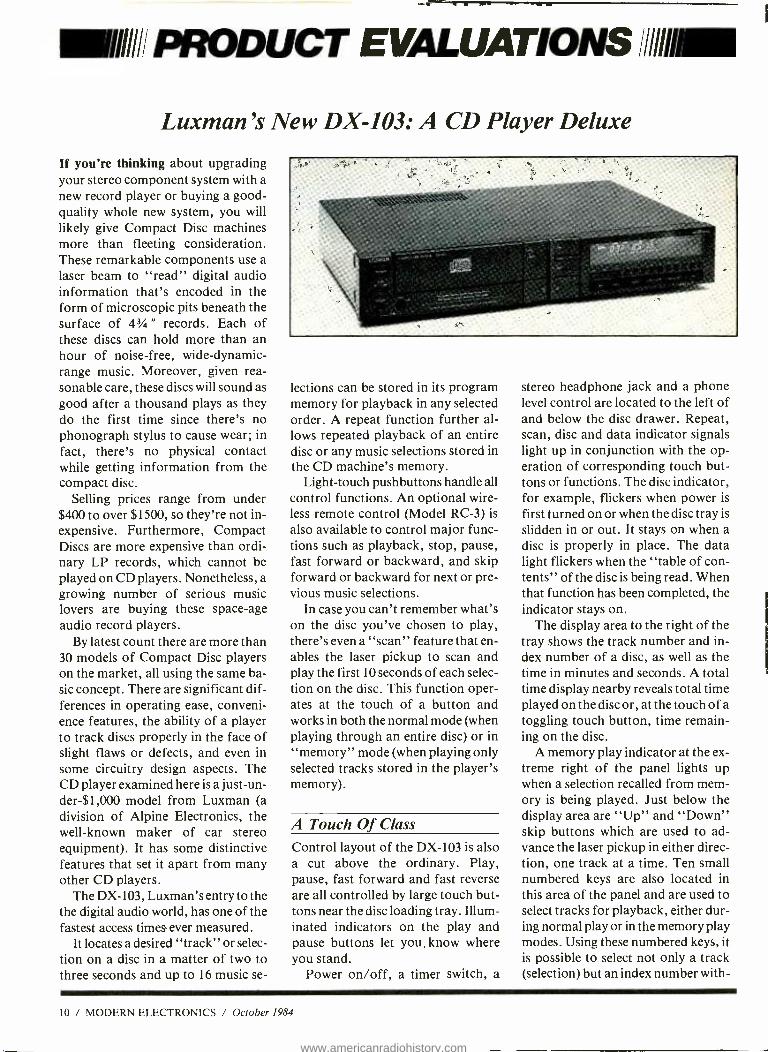
If you're thinking about upgrading your stereo component system with a new record player or buying a good - quality whole new system, you will likely give Compact Disc machines more than fleeting consideration. These remarkable components use a laser beam to "read" digital audio information that's encoded in the form of microscopic pits beneath the surface of 43A " records. Each of these discs can hold more than an hour of noise -free, wide- dynamic- range music. Moreover, given rea- sonable care, these discs will sound as good after a thousand plays as they do the first time since there's no phonograph stylus to cause wear; in fact, there's no physical contact while getting information from the compact disc.
Selling prices range from under $400 to over $1500, so they're not in- expensive. Furthermore, Compact Discs are more expensive than ordi- nary LP records, which cannot be played on CD players. Nonetheless, a growing number of serious music lovers are buying these space -age audio record players.
By latest count there are more than 30 models of Compact Disc players on the market, all using the same ba- sic concept. There are significant dif- ferences in operating ease, conveni- ence features, the ability of a player to track discs properly in the face of slight flaws or defects, and even in some circuitry design aspects. The CD player examined here is a just -un- der- $1,000 model from Luxman (a division of Alpine Electronics, the well -known maker of car stereo equipment). It has some distinctive features that set it apart from many other CD players.
The DX -103, Luxman's entry to the the digital audio world, has one of the fastest access times ever measured.
It locates a desired "track" or selec- tion on a disc in a matter of two to three seconds and up to 16 music se-
lections can be stored in its program memory for playback in any selected order. A repeat function further al- lows repeated playback of an entire disc or any music selections stored in the CD machine's memory.
Light -touch pushbuttons handle all control functions. An optional wire- less remote control (Model RC -3) is also available to control major func- tions such as playback, stop, pause, fast forward or backward, and skip forward or backward for next or pre- vious music selections.
In case you can't remember what's on the disc you've chosen to play, there's even a "scan" feature that en- ables the laser pickup to scan and play the first 10 seconds of each selec- tion on the disc. This function oper- ates at the touch of a button and works in both the normal mode (when playing through an entire disc) or in "memory" mode (when playing only selected tracks stored in the player's memory).
A Touch Of Class
Control layout of the DX -103 is also a cut above the ordinary. Play, pause, fast forward and fast reverse are all controlled by large touch but- tons near the disc loading tray. Illum- inated indicators on the play and pause buttons let you, know where you stand.
Power on /off, a timer switch, a
stereo headphone jack and a phone level control are located to the left of and below the disc drawer. Repeat, scan, disc and data indicator signals light up in conjunction with the op- eration of corresponding touch but- tons or functions. The disc indicator, for example, flickers when power is
first turned on or when the disc tray is
slidden in or out. It stays on when a disc is properly in place. The data light flickers when the "table of con- tents" of the disc is being read. When that function has been completed, the indicator stays on.
The display area to the right of the tray shows the track number and in- dex number of a disc, as well as the time in minutes and seconds. A total time display nearby reveals total time played on the disc or, at the touch of a toggling touch button, time remain- ing on the disc.
A memory play indicator at the ex- treme right of the panel lights up when a selection recalled from mem- ory is being played. Just below the display area are "Up" and "Down" skip buttons which are used to ad- vance the laser pickup in either direc- tion, one track at a time. Ten small numbered keys are also located in this area of the panel and are used to select tracks for playback, either dur- ing normal play or in the memory play modes. Using these numbered keys, it is possible to select not only a track (selection) but an index number with-
10 / MODERN ELECTRONICS / October 1984
www.americanradiohistory.com

in a given selection if the disc being played has such subdivisions encoded within it.
The lower row of touch buttons on the front panel includes a memory call button; a memory clear button; a memory write button (for storing de- sired selections to be played); the "Repeat" button; the "Scan" but- ton, whose function was described earlier, and the "Time" button that causes the display to toggle between "time played" and "time remaining" on the disc being played.
The rear panel of the Luxman DX -103 is equipped with two sets of output jacks -one at fixed level and the other variable in level, the latter controlled by means of the front - panel headphone control.
Lab Performance There is very little point in quoting lab measurements when it comes to Compact Disc players. Just about every one of them exhibits signal-to- noise and dynamic range capabilities in excess of 90 dB. Distortion levels are so low they can be ignored. They have no measurable wow- and -flutter
and stereo separation is usually so high (approaching 90 dB) that all talk of crosstalk between channels be- comes meaningless, too.
Of extreme importance, though, in measuring a CD Player on the test bench is its error correction and servo tracking ability -i.e., its ability to stay "on track" even if the laser misses parts of the digital audio code because of opaque scratches on the surface of the disc or any other reason.
For these tests, we use a special test disc that is deliberately flawed in measurable, controlled amounts. The Luxman DX -103 played com- pletely through our special "defects" disc without ever mistracking or mut- ing. That means if you have a disc with as long an opaque scratch as 900 microns (slightly less than 1 milli- meter), the player will probably ig- nore it completely. Similarly, dust particles as great as 800 microns in diameter, lodged on the surface of any disc, would also be ignored.
The player was also very acceptably resistant to any external shock or vi- bration, remaining "on track" even when tapped lightly on the top and
side surface of the machine while discs were being played.
Sound Tests
The Luxman DX -103 is one of those select machines that has a great num- ber of features but remains relatively easy to use. As for the sound quality it delivers, that is beyond reproach. Luxman has taken the trouble to in- corporate its highly regarded "duo - beta" feedback circuitry into the final, analog stage of the player (which is, after all, an analog signal rather than digital, or we couldn't feed it to our amplifiers).
Some experts have suggested that the chief differences between sounds produced by different CD players may well be caused by differences in that final stage of the player -where digital signals have been converted back to analog signals and then must be amplified by analog audio circuitry much as they would be in any audio equipment. If that is the case, then the Luxman's analog circuitry ironically goes a long way towards making this one of the best sounding CD digital players we have yet tested. -Len Feldman.
CIRCLE 82 ON FREE INFORMATION CARD
Hearing is Believing: JVC's New VHS Hi -Fi Video Cassette Recorder
Video products have not generally been noted for their high -quality audio. Indeed, television sets are of- ten equipped with tiny, unbaffled loudspeakers no better than those found in small radios. Furthermore, connecting the audio signals from a TV receiver to inputs on a stereo component system only underscores how little attention TV makers give to audio.
Good audio quality is not a hall- mark of video cassette recorders ei- ther. In addition to emulating a TV
October 1984 / MODERN ELECTRONICS / I I
www.americanradiohistory.com
PRODUCT EVALUATIONS . ..
set's restricted audio frequency re- sponse, the audio track on video tape typically delivers a high level of tape hiss that's immediately apparent if the VCR's audio outputs are con- nected to a good stereo component system's high -level inputs.
The first company to respond to audio shortcomings of VCRs was Sony, which introduced video ma- chines that incorporate the innova- tive Beta HiFi audio system. Its ex- tended frequency response captures the entire audible range. Further- more, its signal -to -noise ratio -or more importantly, dynamic range (the difference between the softest and loudest sounds that could be recorded and played back) -was im- proved from the unacceptably noisy 40 dB of a standard VCR's audio out- put to an impressive 80 dB. More- over, wow -and -flutter (the wavering of pitch that can be so disturbing when viewing a music video, espe- cially at lower tape speed) was reduc- ed from high levels of more than 0.3% to an inaudible 0.005%.
By retaining the conventional long- itudinal audio track, owners of older Beta -format machines could listen to video tapes made on or for the new Beta HiFi VCRs. (They would play in "low -fi" in this case, of course.) With these advantages, Sony was in effect challenging the dominant VCR - format machines in this country -the VHS system that accounts for more than 70% of VCR sales today.
The Beta HiFi system had barely reached the market, however, when JVC, originator of the VHS format, announced development of -you guessed it -VHS HiFi!
The first VHS HiFi units recently became available, and we were able to acquire JVC's Model HR -D725U and put it through its paces. The VCR's video performance is just about the same as that of any other good VHS machine. Therefore, we concentrated on its audio perfor-
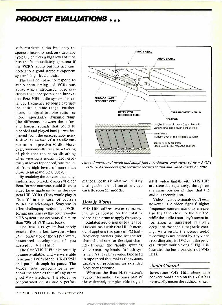
VIDEO SIGNAL
AUDIO SIGNAL
SURFACE LAYER: RECORDED VIDEO
DEEP LAYER: RECORDED AUDIO
TAPE MAGNETC MEDIUM
TAPE BASE
. - Longitudinal audio track (right channel)
Control track
Longitudinal audio track (left channel)
Video track (surface layer of the magnetic coating)
Stereo hi -fi audio track (deep layer of the magnetic coating)
Three -dimensional detail and simplified two -dimensional views of how JVC's VHS Hi -Fi videocassette recorder records sound and video tracks on tape.
mance since this is what would likely distinguish the unit from other video cassette recorder models.
How It Works VHS HiFi utilizes two extra record- ing heads located on the rotating video -head drum to apply frequency - modulated audio signals to the tape. This contrasts with Beta HiFi's meth- od of applying two pairs of FM high - frequency carriers (one for the left channel and one for the right chan- nel) through the rapidly spinning video recording heads. In both sys- tems, it's the relative video tape head to tape speed that makes the systems capable of producing an extended frequency response.
Whereas the Beta HiFi system's audio information becomes part of the wideband, complex video signal
itself, video signals with VHS HiFi are recorded separately, though on the same portion of tape that the audio is recorded on.
Video and audio signals don't mix, however. The video signals' higher frequency content can only magne- tize the tape close to the surface, while the audio recording's stereo in- formation is impressed relatively deep into the tape's magnetic coat- ing. As a result, the deeper audio recording is not erased by any video recording atop it. JVC calls the proc- ess "depth multiplexing." Fig. 1 il- lustrates the basic principle of VHS HiFi.
Audio Control Integrating VHS HiFi along with conventional stereo on this VCR has necessarily meant the addition of sev-
12 / MODERN ELECTRONICS / October 1984
www.americanradiohistory.com
eral front -panel and sub -panel con- trols that ordinarily would not be needed. Two slider controls to the right of the panel are used to adjust recording levels for the HiFi tracks. (Automatic Level Control, or ALC, is used on the conventional tracks, so there has never been a need before to manually adjust audio record level controls.) Calibrated record -level meters (in the form of two rows of light- emitting diodes or LEDS) are located near these slider controls.
Behind a drop -down door near the bottom of the front panel is a sub - panel containing a pair of micro- phone inputs, a stereo phone jack, a Dolby noise reduction on -off switch (used for the conventional audio tracks only, since VHS HiFi is noise - free), an audio dubbing selector switch, and an audio output monitor switch and control.
Audio dubbing is possible only on the conventional tracks. If you were to try to over -record on the VHS HiFi tracks, you would erase the picture as well. But this allows for an interesting feature. The output monitor control will let your hear only the VHS HiFi sound if it is rotated fully in one di-
rection, or conventional sound alone if it is rotated fully in the other direc- tion. If set to a mid -position, you will hear a mixture of both.
This was done in order to allow you to listen to a dubbed narration (recorded after the video recording was made), while at the same time al- lowing you to enjoy the high quality of VHS HiFi sound emanating from the mixed audio outputs.
Test Results
Frequency response in the HiFi mode extended all the way out to 20 kHz, with no more than a ± 2.0 dB devia- tion over the entire audio spectrum. Results were the same at either of the two available tape speeds. (Compare this with the conventional audio re- sponse which, at slowest tape speed, covered a range of from 90 Hz to 3.5 kHz!)
Harmonic distortion at "0 dB" record level was only 0.07% in the HiFi mode, increasing to about 2% at a ± 10 dB recording level. Signal - to -noise measured precisely 80 dB as claimed, whereas using the conven- tional audio tracks it measured no
more than 39 dB without Dolby; 46 dB with it turned on. Wow- and -flut- ter measured 0.006% in the VHS HiFi mode, as against 0.25% using conventional audio.
These lab tests certainly tell the story. But to appreciate fully the significance of VHS HiFi, you have to listen to the playback of a record- ing using this new technology, and then compare it with the type of sound you will get from the conven- tional audio tracks of this or any other VCR. The difference is astound- ing. Suddenly, the sound delivered by the VCR is as high in quality as that of any of your favorite hi -fi sources (good audio tape recordings, your finest LP records, live stereo FM broadcasts, etc.). You will find it, in fact, only marginally inferior to the sound produced from those fan- tastic laser -read Compact Discs.
With Beta HiFi and now VHS - HiFi available on VCRs, there's no longer any reason to settle for poor sound quality with your video enter- tainment. Happily, the cost of these remarkable new systems will add no more than $100 or so to the price of a conventional VCR. -Len Feldman.
CIRCLE 96 ON FREE INFORMATION CARD
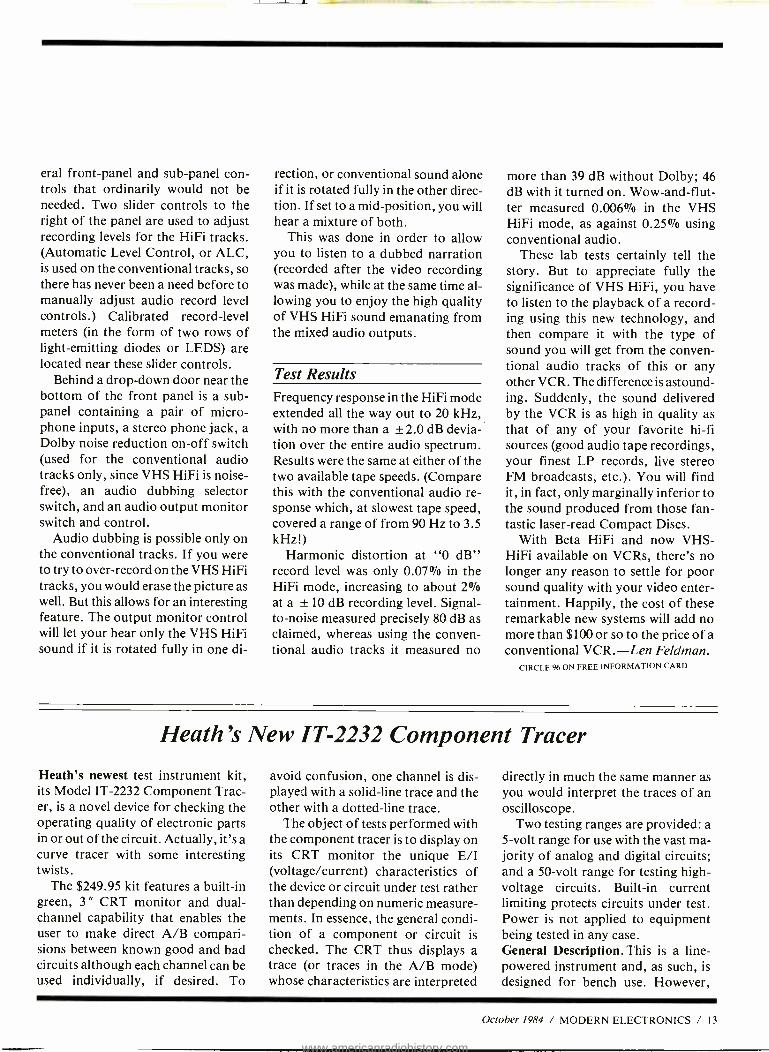
Heath's New IT -2232 Component Tracer
Heath's newest test instrument kit, its Model IT -2232 Component Trac- er, is a novel device for checking the operating quality of electronic parts in or out of the circuit. Actually, it's a curve tracer with some interesting twists.
The $249.95 kit features a built -in green, 3 " CRT monitor and dual - channel capability that enables the user to make direct A/B compari- sions between known good and bad circuits although each channel can be used individually, if desired. To
avoid confusion, one channel is dis- played with a solid -line trace and the other with a dotted -line trace.
The object of tests performed with the component tracer is to display on its CRT monitor the unique E/I (voltage /current) characteristics of the device or circuit under test rather than depending on numeric measure- ments. In essence, the general condi- tion of a component or circuit is checked. The CRT thus displays a trace (or traces in the A/B mode) whose characteristics are interpreted
directly in much the same manner as you would interpret the traces of an oscilloscope.
Two testing ranges are provided: a 5 -volt range for use with the vast ma- jority of analog and digital circuits; and a 50 -volt range for testing high - voltage circuits. Built -in current limiting protects circuits under test. Power is not applied to equipment being tested in any case. General Description. This is a line - powered instrument and, as such, is designed for bench use. However,
October 1984 / MODERN ELECTRONICS / 13
www.americanradiohistory.com
PRODUCT EVALUATIONS ...
since it has a low, flat silhouette di- mensions are 12.5 " deep by 10 " wide by 4 "high and weighs 8.4 lbs., it can easily be tucked under or on top of other bench instruments. Through internal wiring, the component trac- er can be adjusted for either 117- or 220 -volt operation. Power consump- tion is just 22 watts.
The component tracer is designed to be very easy to operate and use. To this end, its front panel contains con- trols only for focus, intensity, verti- cal position, and horizontal position, plus switches for power on /off, test volts (5V and 50V), and mode (A, A /B, B). All other controls for set- ting it up and adjusting it are buried inside the instrument, where they are set once and forgotten.
The component tracer operates in almost the same manner as an or- dinary curve tracer. When it applies a 2.6 test -voltage to a component or circuit during a test, the voltage across and the current through the device or circuit are displayed hori- zontally and vertically, respectively,
on the CRT. If the current flow is
positive, it is displayed in an upward direction. A positive voltage is simi- larly indicated to the right of the CRT screen. The greater the current and /or voltage, the wider the deflec- tion upward and to the right.
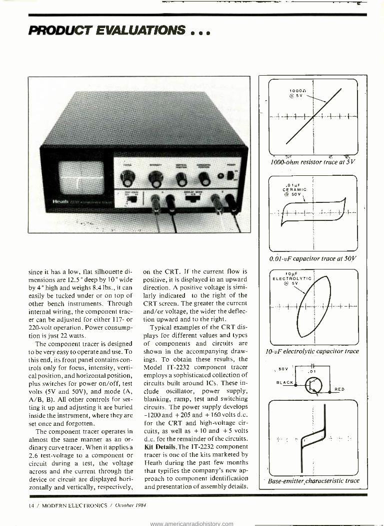
Typical examples of the CRT dis- plays for different values and types of components and circuits are shown in the accompanying draw- ings. To obtain these results, the Model IT -2232 component tracer employs a sophisticated collection of circuits built around ICs. These in- clude oscillator, power supply, blanking, ramp, test and switching circuits. The power supply develops -1200 and + 205 and + 160 volts d.c. for the CRT and high -voltage cir- cuits, as well as + 10 and + 5 volts d.c. for the remainder of the circuits. Kit Details.The IT -2232 component tracer is one of the kits marketed by Heath during the past few months that typifies the company's new ap- proach to component identification and presentation of assembly details.
1000 -ohm resistor trace at 5V
.01µF CERAMIC @ 50V
0.01 -vF capacitor trace at 50 ! "
10µF ELECTROLYTIC
@ 5V
10 -vF electrolytic capacitor trace
Base- emitter characteristic trace
14 / MODERN ELECTRONICS / October 1984
www.americanradiohistory.com
111141...
Until very recently, Heath packag- ed resistors, miniature capacitors with axial leads, and diodes in separate envelopes, usually by type but without regard to value or coding. These components -espe- cially resistors -were tedious to iden- tify. Heath's solution to the problem is to arrange all resistors, miniature capacitors and diodes in taped - together strips (very similar to those used by automatic -insertion equip- ment for assembling printed- circuit cards in factories).
The person who assembles the kit tapes the component strips over the outlines printed on accompanying Taped Component Charts, and has a no -error means for identifying each component as it is called for. The values of the components are printed along the left side of the drawings along with any special coding used to identify them. As you need a com- ponent, all you do is look it up on the charts and snip it from the tape.
In some kits, the components are arranged in ascending order of value and /or according to tolerance and type. In other kits, particularly the IT -2232, Heath has gone one step further by arranging the components in the order in which they are used in the assembly process. The result of this new approach is that kit assem- bly time is considerably reduced, since you don't have to waste time lo- cating each component.
Heath also has take a welcome new tack in the way in which it presents assembly instructions. Up till now, if you built a Heath kit in which one or more printed- circuit board assem- blies had to be wired, a multiplicity of drawings were incorporated into this Assembly Manual proper, with box- ed step -by -step details for compon- ent installation arranged along one or both sides of the drawings. For large, densely populated boards, these drawings had to be presented in partial detail, which meant you'd
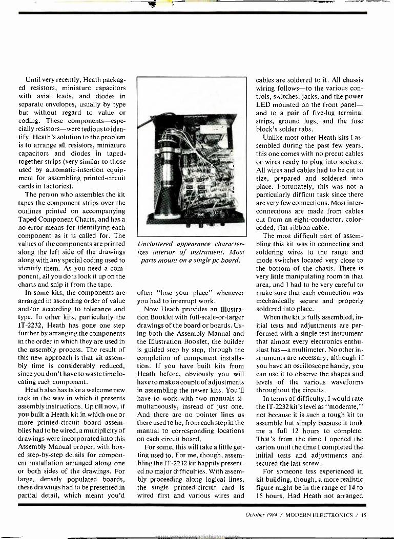
Uncluttered appearance character- izes interior of instrument. Most parts mount on a single pc board.
often "lose your place" whenever you had to interrupt work.
Now Heath provides an Illustra- tion Booklet with full -scale -or- larger drawings of the board or boards. Us- ing both the Assembly Manual and the Illustration Booklet, the builder is guided step by step, through the completion of component installa- tion. If you have built kits from Heath before, obviously you will have to make a couple of adjustments in assembling the newer kits. You'll have to work with two manuals si- multaneously, instead of just one. And there are no pointer lines as there used to be, from each step in the manual to corresponding locations on each circuit board.
For some, this will take a little get- ting used to. For me, though, assem- bling the IT -2232 kit happily present- ed no major difficulties. With assem- bly proceeding along logical lines, the single printed- circuit card is wired first and various wires and
cables are soldered to it. All chassis wiring follows -to the various con- trols, switches, jacks, and the power LED mounted on the front panel - and to a pair of five -lug terminal strips, ground lugs, and the fuse block's solder tabs.
Unlike most other Heath kits I as- sembled during the past few years, this one comes with no precut cables or wires ready to plug into sockets. All wires and cables had to be cut to size, prepared and soldered into place. Fortunately, this was not a particularly difficut task since there are very few connections. Most inter- connections are made from cables cut from an eight- conductor, color - coded, flat -ribbon cable.
The most difficult part of assem- bling this kit was in connecting and soldering wires to the range and mode switches located very close to the bottom of the chasis. There is very little manipulating room in that area, and I had to be very careful to make sure that each connection was mechanically secure and properly soldered into place.
When the kit is fully assembled, in- itial tests and adjustments are per- formed with a single test instrument that almost every electronics enthu- siast has -a multimeter. No other in- struments are necessary, although if you have an oscilloscope handy, you can use it to observe the shapes and levels of the various waveforms throughout the circuits.
In terms of difficulty, I would rate the IT -2232 kit's level as "moderate," not because it is such a tough kit to assemble but simply because it took me a full 12 hours to complete. That's from the time I opened the carton until the time I completed the initial tests and adjustments and secured the last screw.
For someone less experienced in kit building, though, a more realistic figure might be in the range of 14 to 15 hours. Had Heath not arranged
October 1984 / MODERN ELECTRONICS / 15
www.americanradiohistory.com
PRODUCT EVALUATIONS
the smaller components in taped strips in the order in which they're us- ed, that figure could easily have been swelled another hour. Conclusion. With the Model IT -2232 Component Tracer, Heath has brought to the professional elec- tronics technician, as well as the serious experimenter, an additional troubleshooting tool that could speed up servicing. With patient use,
a service technician can whip through a circuit more quickly than with the conventional multimeter, oscillo- scope, or logic probe to isolate a de- fective component without removing it from the circuit. Getting used to the waveshapes will take some time, though, before it becomes second na- ture. Also, with the wide use of inte- grated circuits today, not being able to check out these devices leaves the
instrument only partially useful. In essence, the Component Tracer
is a fine new test instrument that can be a most useful companion to the standard complement of instruments commonly used. As such, its $250 price tag limits its likely purchase to those who make a living servicing electronic equipment, where minutes saved are money made. -Alexander W. Burawa.
CIRCLE 99 ON FREE INFORMATION CARD
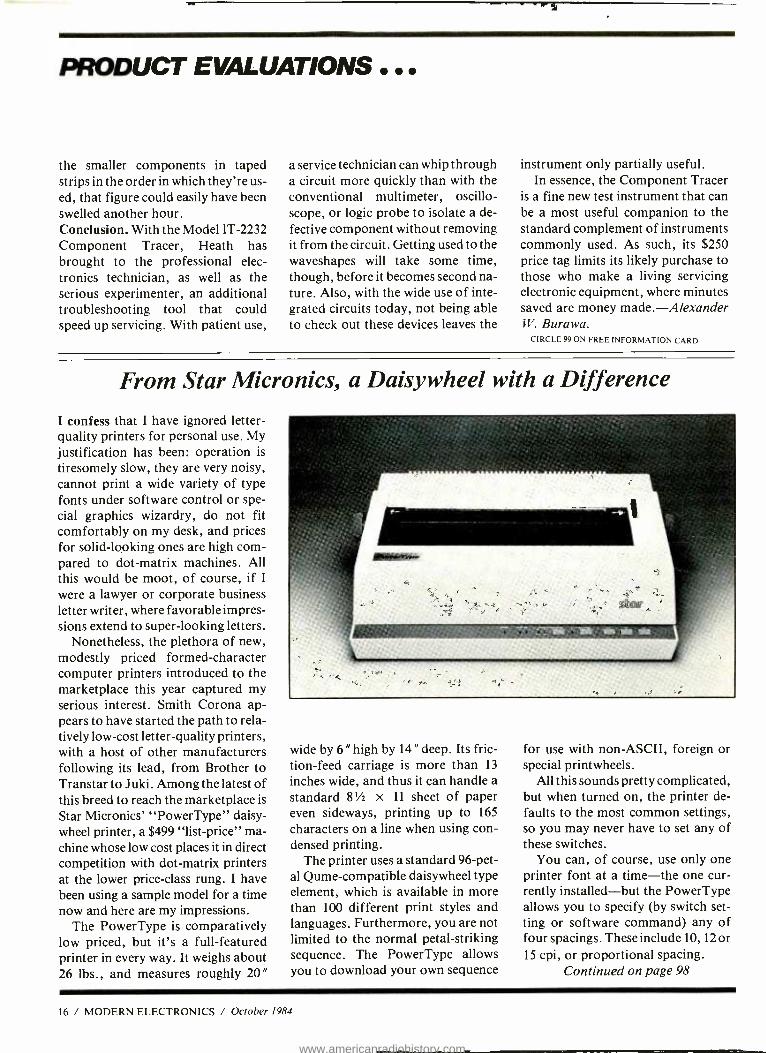
From Star Micronics, a Daisywheel with a Difference
I confess that I have ignored letter - quality printers for personal use. My justification has been: operation is
tiresomely slow, they are very noisy, cannot print a wide variety of type fonts under software control or spe- cial graphics wizardry, do not fit comfortably on my desk, and prices for solid -looking ones are high com- pared to dot -matrix machines. All this would be moot, of course, if I
were a lawyer or corporate business letter writer, where favorable impres- sions extend to super -looking letters.
Nonetheless, the plethora of new, modestly priced formed -character computer printers introduced to the marketplace this year captured my serious interest. Smith Corona ap- pears to have started the path to rela- tively low -cost letter -quality printers, with a host of other manufacturers following its lead, from Brother to Transtar to Juki. Among the latest of this breed to reach the marketplace is
Star Micronics' "PowerType" daisy- wheel printer, a $499 "list- price" ma- chine whose low cost places it in direct competition with dot -matrix printers at the lower price -class rung. I have been using a sample model for a time now and here are my impressions.
The PowerType is comparatively low priced, but it's a full- featured printer in every way. It weighs about 26 lbs., and measures roughly 20"
wide by 6 "high by 14 "deep. Its fric- tion -feed carriage is more than 13
inches wide, and thus it can handle a standard 8'/ x 11 sheet of paper even sideways, printing up to 165
characters on a line when using con- densed printing.
The printer uses a standard 96 -pet- al Qume -compatible daisywheel type element, which is available in more than 100 different print styles and languages. Furthermore, you are not limited to the normal petal- striking sequence. The PowerType allows you to download your own sequence
for use with non -ASCII, foreign or special printwheels.
All this sounds pretty complicated, but when turned on, the printer de- faults to the most common settings, so you may never have to set any of these switches.
You can, of course, use only one printer font at a time -the one cur- rently installed -but the PowerType allows you to specify (by switch set- ting or software command) any of four spacings. These include 10, 12 or 15 cpi, or proportional spacing.
Continued on page 98
16 / MODERN ELECTRONICS / October 1984
www.americanradiohistory.com
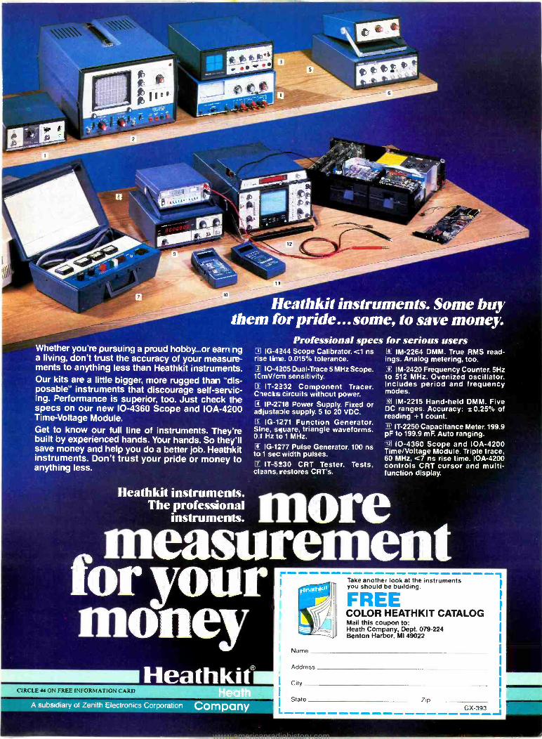
Heathkit instruments. Some buy them for pride... some, to save money:
Professional specs for serious users Whether you're pursuing a proud hobby...or earn ng a living, don't trust the accuracy of your measure- ments to anything less than Heathkit instruments. Our kits are a little bigger, more rugged than "dis- posable" instruments that discourage self- servic- ing. Performance is superior, too. Just check the specs on our new 10 -4360 Scope and IOA -4200 Time -Voltage Module. Get to know our full line of instruments. They're built by experienced hands. Your hands. So they'll save money and help you do a better job. Heathkit instruments. Don't trust your pride or money to anything less.
C IG -4244 Scope Calibrator. <1 ns rise time. 0.015% tolerance. C 10 -4205 Dual -Trace 5 MHz Scope. 1CmVIc-n sensitivity. C IT-2232 Component Tracer. Ciecks circuits without power. C IP -2718 Power Supply. Fixed or adjusta3le supply. 5 to 20 VDC.
C 1G -1271 Function Generator. Sine. square, triangle waveforms. 0.1 Hz to 1 MHz.
C IG -1177 Pulse Generator. 100 ns to 1 sec width pulses. C IT -5230 CRT Tester. Tests, cleans, restores CRT's.
O IM -2264 DMM. True RMS read- ings. Analog metering, too. C IM -2420 Frequency Counter. 5Hz to 512 MHz. Ovenized oscillator. Includes period and frequency modes. â IM -2215 Hand -held DMM. Five DC ranges. Accuracy: ±0.25 of reading +1 count.
IT -2250 Capacitance Meter.199.9 pF to 199.9 mF. Auto ranging. 12, 10 -4360 Scope and IOA -4200 Time /Voltage Module. Triple trace. 60 MHz. <7 ns rise time. IOA -4200 controls CRT cursor and multi- function display.
Heathkit instruments. The professional
instruments.
CIRCLE 44 ON FREE INFORMATION CARD
A Subsidiary of Zenith Electronics Corporation Company
Take another look at the instruments you should be building.
FREE COLOR HEATHKIT CATALOG Mail this coupon to: Heath Company, Dept. 079 -224 Benton Harbor, MI 49022
Name
Address
I City
I State Zip GX-393
www.americanradiohistory.com
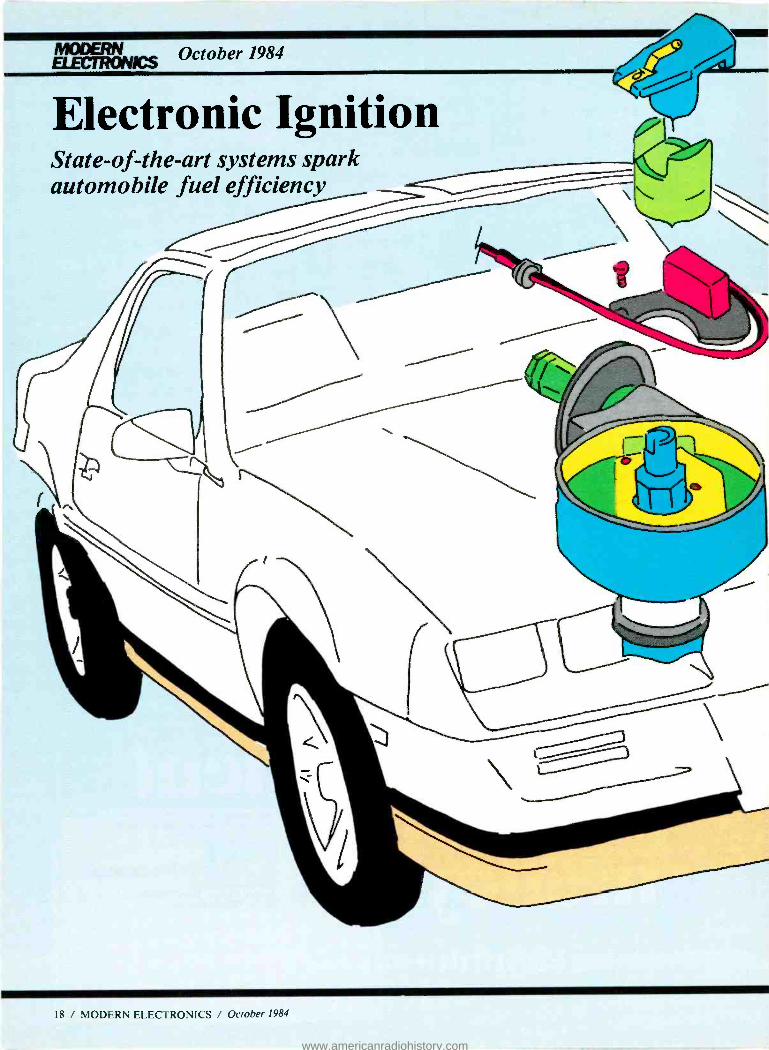
MODERN October 1984 ELECTRONICS
Electronic Ignition State -of -the -art systems spark automobile fuel efficiency
1R / MODERN ELECTRONICS / October 1984
www.americanradiohistory.com
By Ron Cogan
Mention automotive electron- ics and many of us think only of the more exotic ap-
plications in the modern automobile: automatic interior climate control, synthesized vocalized warning sys-
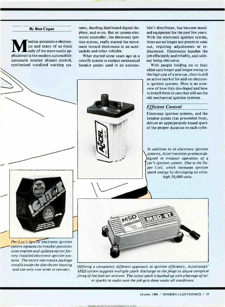
Per -Lux's Igni orronic ignition system replaces the breaker points on most engines and updates earlier fac- tory- installed electronic ignition sys- tems. The entire electronics package installs inside the distributor housing and has only two wires to connect.
tems, dazzling dashboard digital dis- plays, and so on. But an unseen elec- tronic controller, the electronic igni- tion system, really started the move- ment toward electronics in an auto- mobile and other vehicles.
What started some years ago as a retrofit system to replace mechanical breaker points used in an automo-
bile's distributor, has become stand- ard equipment for the past few years. With the electronic ignition system, there are no longer any points to wear out, requiring adjustments or re- placement. Electronics handles the job efficiently and reliably, and with- out being obtrusive.
With people holding on to their older cars longer and longer owing to the high cost of a new car, there is still an active market for add -on electron- ic ignition systems. Here is an over- view of how they developed and how to install them in cars that still use the old mechanical ignition systems.
Efficient Control Electronic ignition systems, and the breaker points that preceeded them, deliver an appropriately -timed spark of the proper duration to each cylin-
In addition to its electronic ignition systems, Accel has other products de- signed to enhance operation of a car's ignition system. One is the Su- per Coil, which increases ignition spark energy by developing an ultra-
high 50,000 volts.
Offering a completely different approach to ignition efficiency, Autotronics' MSD system supplies multiple -spark discharge to the plugs to assure complete firing of the fuel /air mixture. The initial spark is backed up with a barrage of lat-
er sparks to make sure the job gets done under all conditions.
October 1984 / MODERN ELECTRONICS / 19
www.americanradiohistory.com
der's spark plug. In turn, this fires the air /fuel mixture in the combus- tion chambers to produce the horse- power that ulitmately drives the car's wheels. The sequence of events is an impressive orchestration of fuel /air intake, firing, and exhuast of the wastes resutling from ignition. The ignition system must work with split - second timing to make the engine work with peak efficiency and thus provide maximum economy.
The electronic ignition system is
unquestionably technologically su- perior to the mechanical points sys- tem. To begin with, the electronic ig- nition does not wear out, nor does its performance degrade with time. Breaker points never work better than when they are first installed, since they are mechanical devices that immediately begin a slow wear- ing process as soon as the engine is brought to life. Since there are no moving parts subject to fatigue in it, the electronic ignition does its job with full efficiency as soon as it is in- stalled and will continue to do so just as efficiently years later.
Another advantage of the elec- tronic ignition system is that it saves time and money during tune -ups. Since there are no mechanical parts to wear, there are none to replace during routine maintenance. A tune - up simply consists of changing spark plugs and occasionally replacing the rotor, distributor cap, and plug wires as they wear after many thousands of miles. Your engine's timing does not change once it has been initially set during installation of the electronic ignition system.
Enter the Electronics Age In an effort to eke maximum perfor- mance from their powerplants, the hot rodders of the 1960s began ex- perimenting with electronic ignition and, unknowingly, brought the auto- mobile into the electronics age. By
1972, Chrysler recognized the bene- fits of electronic ignition and began installing systems of its own manu-
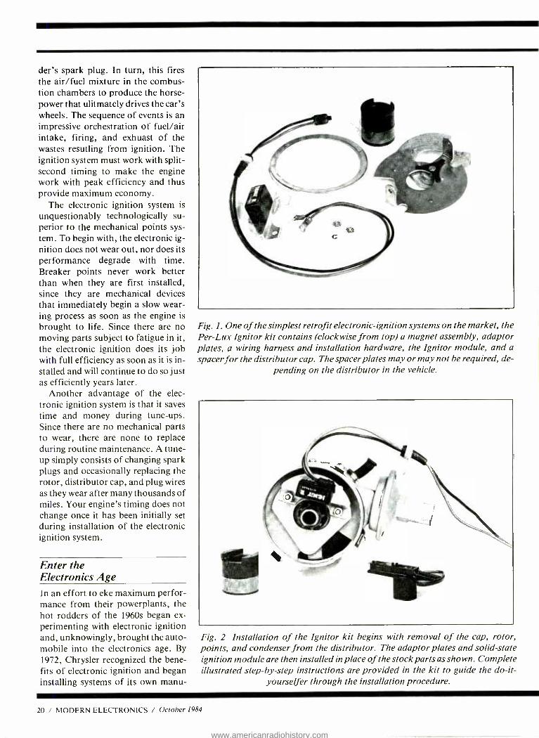
Fig. 1. One of the simplest retrofit electronic- ignition systems on the market, the Per -Lux Ignitor kit contains (clockwise from top) a magnet assembly, adaptor plates, a wiring harness and installation hardware, the Ignitor module, and a spacer for the distributor cap. The spacer plates may or may not be required, de-
pending on the distributor in the vehicle.
Fig. 2., Installation of the Ignitor kit begins with removal of the cap, rotor, points and condenser from the distributor. The adaptor plates and solid -state ignition module are then installed in place of the stock parts as shown. Complete illustrated step -by -step instructions are provided in the kit to guide the do-it -
yourselfer through the installation procedure.
20 / MODERN ELECTRONICS / October 1984
www.americanradiohistory.com
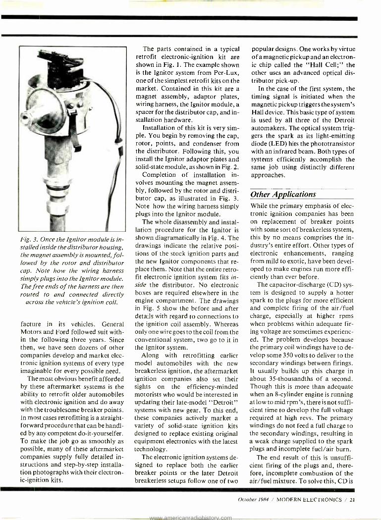
Fig. 3. Once the Ignitor module is in- stalled inside the distributor housing, the magnet assembly is mounted, fol- lowed by the rotor and distributor cap. Note how the wiring harness simply plugs into the Ignitor module. The free ends of the harness are then routed to and connected directly
across the vehicle's ignition coil.
facture in its vehicles. General Motors and Ford followed suit with- in the following three years. Since then, we have seen dozens of other companies develop and market elec- tronic ignition systems of every type imaginable for every possible need.
The most obvious benefit afforded by these aftermarket systems is the ability to retrofit older automobiles with electronic ignition and do away with the troublesome breaker points. In most cases retrofitting is a straight- forward procedure that can be handl- ed by any competent do- it- yourselfer. To make the job go as smoothly as possible, many of these aftermarket companies supply fully detailed in- structions and step -by -step installa- tion photographs with their electron- ic- ignition kits.
The parts contained in a typical retrofit electronic- ignition kit are shown in Fig. 1. The example shown is the Ignitor system from Per -Lux, one of the simplest retrofit kits on the market. Contained in this kit are a magnet assembly, adaptor plates, wiring harness, the Ignitor module, a spacer for the distributor cap, and in- stallation hardware.
Installation of this kit is very sim- ple. You begin by removing the cap, rotor, points, and condenser from the distributor. Following this, you install the Ignitor adaptor plates and solid -state module, as shown in Fig. 2.
Completion of installation in- volves mounting the magnet assem- bly, followed by the rotor and distri- butor cap, as illustrated in Fig. 3. Note how the wiring harness simply plugs into the Ignitor module.
The whole disassembly and instal- lation procedure for the Ignitor is shown diagramatically in Fig. 4. The drawings indicate the relative posi- tions of the stock ignition parts and the new Ignitor components that re- place them. Note that the entire retro- fit electronic ignition system fits in- side the distributor. No electronic boxes are required elsewhere in the engine compartment. The drawings in Fig. 5 show the before and after details with regard to connections to the ignition coil assembly. Whereas only one wire goes to the coil from the conventional system, two go to it in the Ignitor system.
Along with retrofitting earlier model automobiles with the new breakerless ignition, the aftermarket ignition companies also set their sights on the efficiency- minded motorists who would be interested in updating their late -model "Detroit" systems with new gear. To this end, these companies actively market a variety of solid -state ignition kits designed to replace existing original equipment electronics with the latest technology.
The electronic ignition systems de- signed to replace both the earlier breaker points or the later Detroit breakerless setups follow one of two
popular designs. One works by virtue of a magnetic pickup and an electron- ic chip called the "Hall Cell;" the other uses an advanced optical dis- tributor pick -up.
In the case of the first system, the timing signal is initiated when the magnetic pickup triggers the system's Hall device. This basic type of system is used by all three of the Detroit automakers. The optical system trig- gers the spark as its light- emitting diode (LED) hits the phototransistor with an infrared beam. Both types of systems efficiently accomplish the same job using distinctly different approaches.
Other Applications While the primary emphasis of elec- tronic ignition companies has been on replacement of breaker points with some sort of breakerless system, this by no means comprises the in- dustry's entire effort. Other types of electronic enhancements, ranging from mild to exotic, have been devel- oped to make engines run more effi- ciently than ever before.
The capacitor- discharge (CD) sys- tem is designed to supply a hotter spark to the plugs for more efficient and complete firing of the air /fuel charge, especially at higher rpms when problems within adequate fir- ing voltage are sometimes experienc- ed. The problem develops because the primary coil windings have to de- velop some 350 volts to deliver to the secondary windings between firings. It usually builds up this charge in about 35- thousandths of a second. Though this is more than adequate when an 8- cylinder engine is running at low to mid rpm's, there is not suffi- cient time to develop the full voltage required at high revs. The primary windings do not feed a full charge to the secondary windings, resulting in a weak charge supplied to the spark plugs and incomplete fuel /air burn.
The end result of this is unsuffi- cient firing of the plugs and, there- fore, incomplete combustion of the air /fuel mixture. To solve this, CD is
October 1984 / MODERN ELECTRONICS / 21
www.americanradiohistory.com
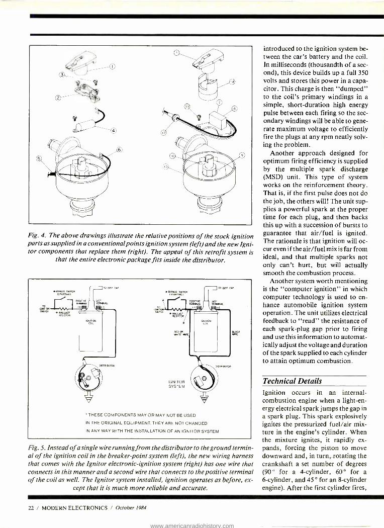
Fig. 4. The above drawings illustrate the relative positions of the stock ignition parts as supplied in a conventional points ignition system (left) and the new Igni- tor components that replace them fright). The appeal of this retrofit system is
that the entire electronic package fits inside the distributor.
TO IGNITION SIBTCM
w BYPASS SWITCH (STARTINGI
BALULST RESISTOR
POSITIVE TEIMUL
TO OST UP
OIST TERMINAL
IGNITION COIL
TO AIWA SWITCH
BYPASS SWITCH ( STARTING
BALLAST RESISTOR
TO DST CAP
POSITIVE TERMINAL
+1'T'¡
PST LT AL
r (-1
RED OR BLOC, PRATE WIRE WIRE
IGNITOR SYSTEM
THESE COMPONENTS MAY OR MAY NOT BE USED
IN THE ORIGINAL EQUIPMENT. THEY ARE NOT CHANGED
IN ANY WAY WITH THE INSTALLATION OF AN IGNITOR SYSTEM
Fig. 5. Instead of a single wire running from the distributor to the ground termin- al of the ignition coil in the breaker point system (left), the new wiring harness that comes with the Ignitor electronic- ignition system (right) has one wire that connects in this manner and a second wire that connects to the positive terminal of the coil as well. The Ignitor system installed, ignition operates as before, ex-
cept that it is much more reliable and accurate.
introduced to the ignition system be- tween the car's battery and the coil. In milliseconds (thousandth of a sec- ond), this device builds up a full 350 volts and stores this power in a capa- citor. This charge is then "dumped" to the coil's primary windings in a simple, short -duration high energy pulse between each firing so the sec- ondary windings will be able to gene- rate maximum voltage to efficiently fire the plugs at any rpm neatly solv- ing the problem.
Another approach designed for optimum firing efficiency is supplied by the multiple spark discharge (MSD) unit. This type of system works on the reinforcement theory. That is, if the first pulse does not do the job, the others will! The unit sup- plies a powerful spark at the proper time for each plug, and then backs this up with a succession of bursts to guarantee that air /fuel is ignited. The rationale is that ignition will oc- cur even if the air /fuel mix is far from ideal, and that multiple sparks not only can't hurt, but will actually smooth the combustion process.
Another system worth mentioning is the "computer ignition" in which computer technology is used to en- hance automobile ignition system operation. The unit utilizes electrical feedback to "read" the resistance of each spark -plug gap prior to firing and use this information to automat- ically adjust the voltage and duration of the spark supplied to each cylinder to attain optimum combustion.
Technical Details Ignition occurs in an internal - combustion engine when a light-en - ergy electrical spark jumps the gap in a spark plug. This spark explosively ignites the pressurized fuel /air mix- ture in the engine's cylinder. When the mixture ignites, it rapidly ex- pands, forcing the piston to move downward and, in turn,.rotating the crankshaft a set number of degrees (90 ° for a 4- cylinder, 60 ° for a 6- cylinder, and 45 ° for an 8- cylinder engine). After the first cylinder fires,
22 / MODERN ELECTRONICS / October 1984
www.americanradiohistory.com
spark energy is applied to the second, then the third, and so forth until all cylinders have fired and the crank- shaft had made one complete rota- tion. To keep the engine going, this sequence is repeated over and over.
From the foregoing, it should be obvious that the timing sequence is of critical importance. Precision con- trol is essential for maximum power to be developed, best fuel economy, and mimimum generation of air pol- lutants.
With a conventional electrome- chanical ignition system (Fig. 6), tim- ing is controlled by elements that are prone to fatigue and wear. This de- terioration begins the moment the mechanical elements are installed and steadily increases as time goes by.
As the parts fatigue and wear, the spark can lead or lag the optimum moment in time when it should oc- cur. (This optimum time is called "top dead center," commonly ab- breviated TDC.) If a spark does not occur when the piston is at its mini- mum distance from the spark plug, (top of the cylinder chamber), the fuel /air mixture burn will be incom- plete. In terms of performance, this will result in reduced torque (reduced horsepower). Furthermore, unburn- ed fuel will exit the exhaust, resulting in higher operating cost and increas- ed air pollution. If this condition is allowed to continue, deterioration will accelerate, until the engine runs rough and begins "lugging" (turning over slower and slower even with in- creased pressure on the accelerator pedal).
To keep an internal- combustion engine that uses electromechanical ignition in reasonable operating or- der, it is necessary to have it relatively frequently tuned and almost as fre- quently have the points replaced.
The move to electronic ignition (Fig. 7) brings some obvious and not so obvious benefits. Though this sys- tem does not do away with the need for periodic tuneups, it does have the advantage of providing near -optimal performance for a longer period of time with little or no maintenance.
Return spring
Breaker points
Vehicle ground - ( -V from battery)
Rotating distributor cam
n
+12V from battery
To > distributor
Ignition coil
Vehicle ground
Fig. 6. In the electromechanical ignition system, timing is controlled by a points /cam arrangement that is subject to wear and fatigue. The cam rotates so that its peaks close the breaker points in synchronism with the firing require- ments of the cylinders in the engine. Constant opening and closing of and spark-
ing across the contacts of the points leads to deterioration.
L_ -__ Sensor coil
Rotating ferromagnetic wheel
1+ Battery
To distributor
1V
Ignition coil
Control circuit
F'(r,ver nrlifie
ELECTRONIC IGNITION CONTROL MODULE
Switching amplifier
J-
Fig. 7. The all -electronic ignition system presents a sharp contrast to the electro- mechanical system. The cam assembly is replaced by a ferromagnetic- wheel /sen- sor -coil assembly, while the points are replaced by a compact electronic control module. Instead of opening and closing mechanical contacts, the electronic -igni- tion system turns on and off a switching transistor. There are no moving parts to
wear out in this all- electronic system.
You will still have to replace spark plugs and cables, though not as fre- quently as with the traditional system.
An electronic ignition system does not completely change how things are done in the internal- combustion powerplant. In fact, it changes very little. The basic ignition element - the ignition coil- remains the same. However, in place of the rotating
breaker cam, the electronic- ignition system uses a rotating ferromagnetic wheel, which has the same number of "cogs" on it as there are cylinders in the engine. This cogged wheel serves as an angular -position generator that tells the system when to fire any given cylinder's fuel /air mixture.
Replacing the actual breaker points in the electronic- ignition system is an
October 1984 / MODERN ELECTRONICS / 23
www.americanradiohistory.com
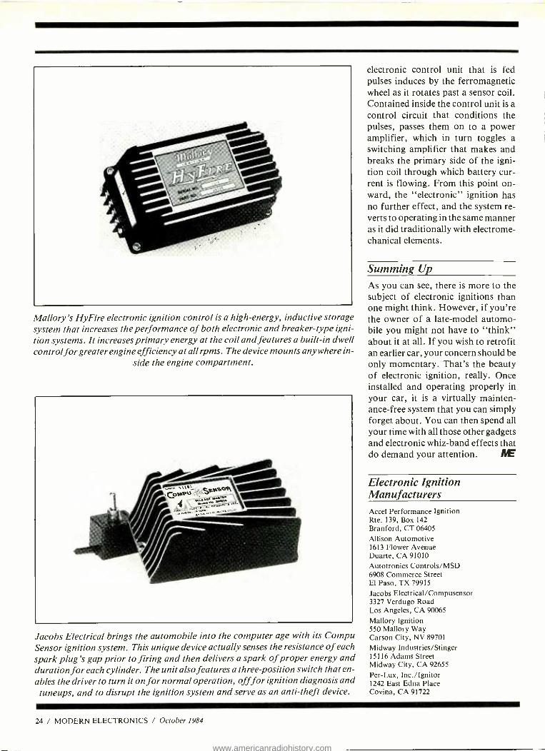
Mallory's HyFire electronic ignition control is a high- energy, inductive storage system that increases the performance of both electronic and breaker -type igni- tion systems. It increases primary energy at the coil and features a built -in dwell control for greater engine efficiency at all rpms. The device mounts anywhere in-
side the engine compartment.
Jacobs Electrical brings the automobile into the computer age with its Compu Sensor ignition system. This unique device actually senses the resistance of each spark plug's gap prior to firing and then delivers a spark of proper energy and duration for each cylinder. The unit also features a three position switch that en- ables the driver to turn it on for normal operation, off for ignition diagnosis and
tuneups, and to disrupt the ignition system and serve as an anti -theft device.
24 / MODERN ELECTRONICS / October 1984
electronic control unit that is fed pulses induces by the ferromagnetic wheel as it rotates past a sensor coil. Contained inside the control unit is a control circuit that conditions the pulses, passes them on to a power amplifier, which in turn toggles a switching amplifier that makes and breaks the primary side of the igni- tion coil through which battery cur- rent is flowing. From this point on- ward, the "electronic" ignition has no further effect, and the system re- verts to operating in the same manner as it did traditionally with electrome- chanical elements.
Summing Up
As you can see, there is more to the subject of electronic ignitions than one might think. However, if you're the owner of a late -model automo- bile you might not have to "think" about it at all. If you wish to retrofit an earlier car, your concern should be only momentary. That's the beauty of electronic ignition, really. Once installed and operating properly in your car, it is a virtually mainten- ance -free system that you can simply forget about. You can then spend all your time with all those other gadgets and electronic whiz -band effects that do demand your attention. IYE
Electronic Ignition Manufacturers Accel Performance Ignition Rte. 139, Box 142 Branford, CT 06405
Allison Automotive 1613 Flower Avenue Duarte, CA 91010 Autotronics Controls /MSD 6908 Commerce Street El Paso, TX 79915
Jacobs Electrical /Compusensor 3327 Verdugo Road Los Angeles, CA 90065
Mallory Ignition 550 Mallory Way Carson City, NV 89701
Midway Industries /Stinger 15116 Adams Street Midway City, CA 92655
Per -Lux, Inc. /Ignitor 1242 East Edna Place Covina, CA 91722
www.americanradiohistory.com
03 MASTER THE NEW ELECTRONICS WITH McGRAW- HILL'S
Ele etral le S S die S The fast, easy and low cost way to
meet the challenges of today's electronic innovations. A unique
learning series that's as innovative as the circuitry it explains, as
fascinating as the experiments you build and explore.
From digital logic to the latest 32 -bit microprocessor, the McGraw - Hill Contemporary Electronics Series puts you into the electronic picture one easy step at a time. Twelve unique Concept Modules, sent to you one every 4-6 weeks, give you a handle on subjects like optoelectron- ics, transistors, integrated circuits, logic circuits, and more.
Each Concept Module goes right to the heart of the matter. You waste no time on extraneous material or outdated history. It's a fast, efficient, and lively learning experience. .. a non -traditional approach to the most modern of subject matter.
Unique Interactive Instruction With each module, you receive
a McGraw -Hill Action Audio Cassette. Each tape is a dynamic discussion that drives home the key facts about the subject. Your learning With your first module, you get this solderless breadboarding system. You'll use it through- out the series to build elec- tronic circuits and bring concepts to life.
experience is reinforced through interaction with vividly illustrated text, audio cassettes, and actual electronic experiments. Indexed binders preserve backup material, notes, and tapes for convenient referral.
Perform Experiments
in Contemporary Electronics Throughout your series, lab-
oratory experiments reinforce every significant point. This essential experience ...dynamic, hands -on demonstrations of theory in practice.. .
will help you master principles that apply all the way up to tomorrow's latest VLSI (Very Large Scale Integrated) circuitry.
In your very first module, you'll use integrated circuits to build a digital oscillator, verifying its operation with a light emitting diode (LED). You'll learn to identify passive and active components, understand concepts common to all electronic circuits.
For Anyone Interested in Electronics The Contemporary Electronics
Series is designed for anyone from hobbyist to professional. It's for you if you're looking for new fields of interest...if you're a teacher who
Ca
.. ..;,
wx.
wants an update in con-
temporary circuits...a manager or supervisor in an electronics plant...a doctor, an engineer, a chemist who fmds electronics playing an increasingly important role in your work. It's even for electronics engineers or technicians who feel their training needs freshening up. It's the quickest,
most convenient, -° t probably least
expensive way to r do it. And the only one that gives you hands -on experience.
15 -Day No -Risk Trial To order your first module with-
out risk, send the postage -paid card today. Examine it for 15 days under the terms of the order form and see how the Contemporary Electronics Series gets you into today's electronics. If card has been used, write us for ordering information.
F/ McGraw -Hil1
Continuing Education Center T 3939 Wisconsin Ave. 11 Washington, D.C. 20016
CIRCLE 17 ON FREE INFORMATION CARD
www.americanradiohistory.com
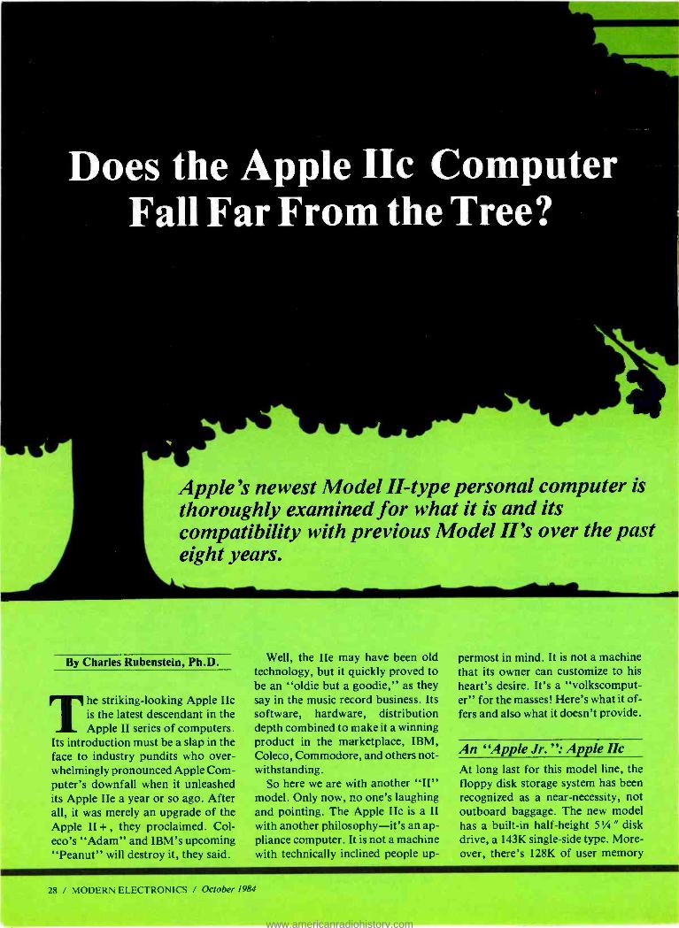
Does the Apple IIc Computer Fall Far From the Tree?
Apple's newest Model II -type personal computer is thoroughly examined for what it is and its compatibility with previous Model II's over the past eight years.
By Charles Rubenstein, Ph.D.
The striking -looking Apple IIc is the latest descendant in the Apple II series of computers.
Its introduction must be a slap in the face to industry pundits who over- whelmingly pronounced Apple Com- puter's downfall when it unleashed its Apple IIe a year or so ago. After all, it was merely an upgrade of the Apple II + , they proclaimed. Col - eco's "Adam" and IBM's upcoming "Peanut" will destroy it, they said.
Well, the IIe may have been old technology, but it quickly proved to be an "oldie but a goodie," as they say in the music record business. Its software, hardware, distribution depth combined to make it a winning product in the marketplace, IBM, Coleco, Commodore, and others not- withstanding.
So here we are with another "II" model. Only now, no one's laughing and pointing. The Apple IIc is a II with another philosophy -it's an ap- pliance computer. It is not a machine with technically inclined people up-
permost in mind. It is not a machine that its owner can customize to his heart's desire. It's a "volkscomput- er" for the masses! Here's what it of- fers and also what it doesn't provide.
An "Apple Jr.": Apple IIc At long last for this model line, the floppy disk storage system has been recognized as a near -necessity, not outboard baggage. The new model has a built -in half- height 5'/4 " disk drive, a 143K single -side type. More- over, there's 128K of user memory
28 / MODERN ELECTRONICS / October 1984
www.americanradiohistory.com
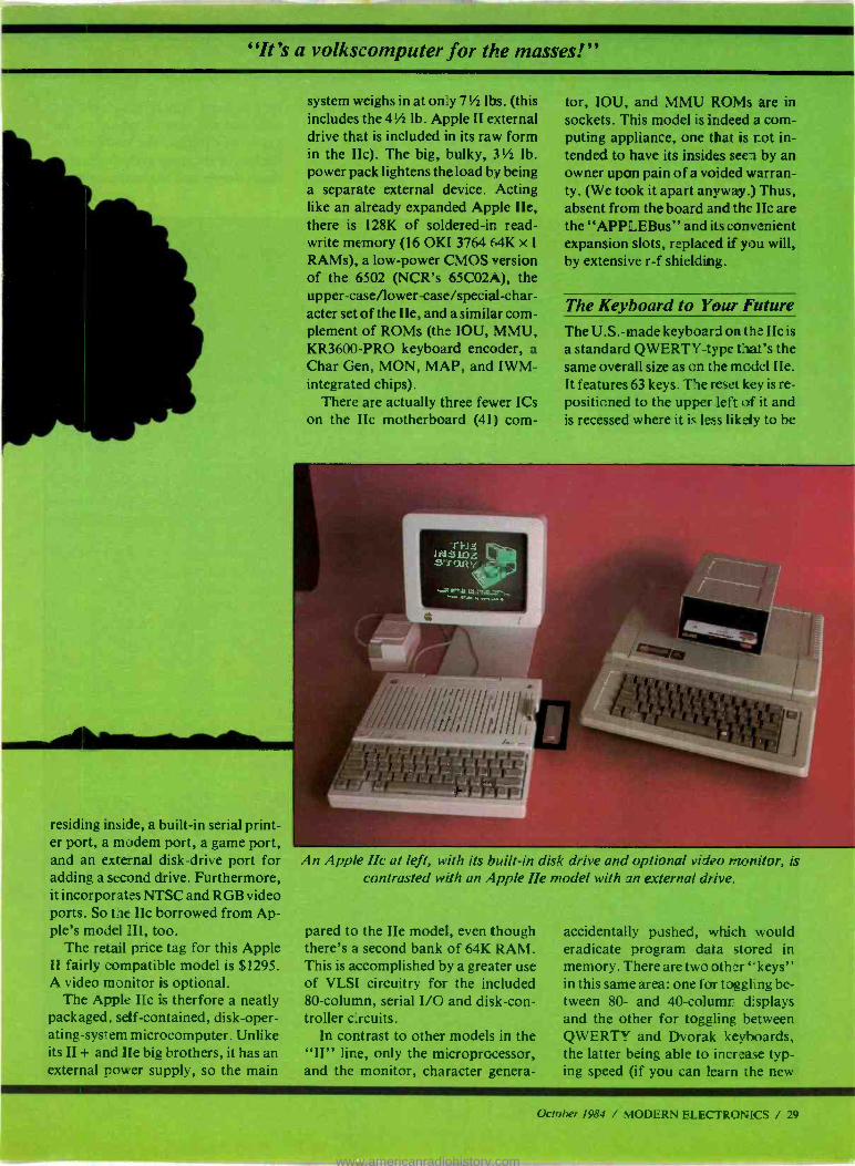
"It's a volkscomputer for the masses!
system weighs in at only 7'h lbs. (this includes the 4'h lb. Apple II external drive that is included in its raw form in the Ilc). The big, bulky, 3'h lb. power pack lightens the load by being a separate external device. Acting like an already expanded Apple IIe, there is 128K of soldered -ir read - write memory (16 OKI 3764 64K x 1
RAMs), a low -power CMOS version of the 6502 (NCR's 65CO2A), the upper- case /lower -case /special -char- acter set of the IIe, and a similar com- plement of ROMs (the IOU, MMU, KR3600 -PRO keyboard encoder, a Char Gen, MON, MAP, and IWM- integrated chips).
There are actually three fewer ICs on the Be motherboard (41) corn-
tor, IOU, and MMU ROMs are in sockets. This model is indeed a corn - puting appliance, one that is not in- tended to have its insides seen by an owner upon pain of a voided warran- ty. (We took it apart anyway.) Thus, absent from the board and the lIc are the "APPLEBus" and its convenient expansion slots, replaced if you will, by extensive r -f shielding.
The Keyboard to Your Future The U.S. -made keyboard on the llc is
a standard QWERTY -type that's the same overall size as on the model IIe. It features 63 keys. The reset key is re- positioned to the upper left of it and is recessed where it is less likely to be
residing inside, a built -in serial print- er port, a modem port, a game port, and an external disk -drive port for adding a second drive. Furthermore, it incorporates NTSC and RGB video ports. So the IIc borrowed from Ap- ple's model III, too.
The retail price tag for this Apple II fairly compatible model is $1295. A video monitor is optional.
The Apple Idc is therfore a neatly packaged, self- contained, disk -oper- ating -system microcomputer. Unlike its II + and Ile big brothers, it has an external power supply, so the main
An Apple IIc at left, with its built -in disk drive and optional video monitor, is contrasted with an Apple Ile model with an external drive.
pared to the IIe model, even though there's a second bank of 64K RAM. This is accomplished by a greater use of VLSI circuitry for the included 80- column, serial I/O and disk -con- troller circuits.
In contrast to other models in the "II" line, only the microprocessor, and the monitor, character genera-
accidentally pushed, which would eradicate program data stored in memory. There are two other ` °keys" in this same area: one for toggling be- tween 80- and 40- column displays and the other for toggling between QWERTY and Dvorak keyboards, the latter being able to increase typ- ing speed (if you can learn the new
Oc!ober 1984 / MODERN ELECTRONICS / 29
www.americanradiohistory.com
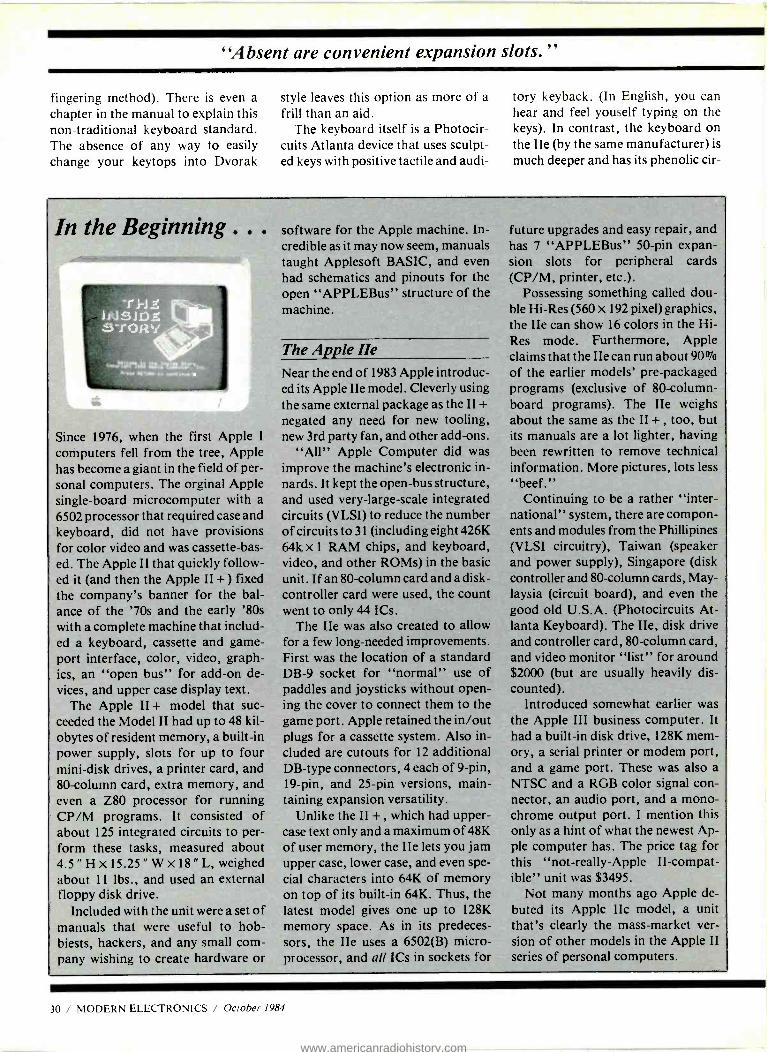
"Absent are convenient expansion slots."
fingering method). There is even a chapter in the manual to explain this non -traditional keyboard standard. The absence of any way to easily change your keytops into Dvorak
style leaves this option as more of a frill than an aid.
The keyboard itself is a Photocir- cuits Atlanta device that uses sculpt- ed keys with positive tactile and audi-
tory keyback. (In English, you can hear and feel youself typing on the keys). In contrast, the keyboard on the IIe (by the same manufacturer) is
much deeper and has its phenolic cir-
In the Beginning .. .
..SYrlaa .
...tor who ..s.,,,
Since 1976, when the first Apple I
computers fell from the tree, Apple has become a giant in the field of per- sonal computers. The orginal Apple single -board microcomputer with a
6502 processor that required case and keyboard, did not have provisions for color video and was cassette -bas- ed. The Apple II that quickly follow- ed it (and then the Apple II + ) fixed the company's banner for the bal- ance of the '70s and the early '80s with a complete machine that includ- ed a keyboard, cassette and game - port interface, color, video, graph- ics, an "open bus" for add -on de- vices, and upper case display text.
The Apple II + model that suc- ceeded the Model II had up to 48 kil- obytes of resident memory, a built -in power supply, slots for up to four mini -disk drives, a printer card, and 80- column card, extra memory, and even a Z80 processor for running CP /M programs. It consisted of about 125 integrated circuits to per- form these tasks, measured about 4.5 "Hx15.25 "Wx18 "L,weighed about 11 lbs., and used an external floppy disk drive.
Included with the unit were a set of manuals that were useful to hob - biests, hackers, and any small com- pany wishing to create hardware or
software for the Apple machine. In- credible as it may now seem, manuals taught Applesoft BASIC, and even had schematics and pinouts for the open "APPLEBus" structure of the machine.
The Apple Ile Near the end of 1983 Apple introduc- ed its Apple IIe model. Cleverly using the same external package as the II +
negated any need for new tooling, new 3rd party fan, and other add -ons.
"All" Apple Computer did was improve the machine's electronic in- nards. It kept the open -bus structure, and used very -large -scale integrated circuits (VLSI) to reduce the number of circuits to 31 (including eight 426K 64k x 1 RAM chips, and keyboard, video, and other ROMs) in the basic unit. If an 80- column card and a disk - controller card were used, the count went to only 44 ICs.
The Ile was also created to allow for a few long- needed improvements. First was the location of a standard DB -9 socket for "normal" use of paddles and joysticks without open- ing the cover to connect them to the game port. Apple retained the in /out plugs for a cassette system. Also in- cluded are cutouts for 12 additional DB -type connectors, 4 each of 9 -pin, 19 -pin, and 25 -pin versions, main- taining expansion versatility.
Unlike the II + , which had upper- case text only and a maximum of 48K of user memory, the IIe lets you jam upper case, lower case, and even spe- cial characters into 64K of memory on top of its built -in 64K. Thus, the latest model gives one up to 128K
memory space. As in its predeces- sors, the IIe uses a 6502(B) micro- processor, and all ICs in sockets for
future upgrades and easy repair, and has 7 "APPLEBus" 50 -pin expan- sion slots for peripheral cards (CP /M, printer, etc.).
Possessing something called dou- ble Hi -Res (560 x 192 pixel) graphics, the IIe can show 16 colors in the Hi- Res mode. Furthermore, Apple claims that the Ile can run about 90% of the earlier models' pre -packaged programs (exclusive of 80- column- board programs). The IIe weighs about the same as the II + , too, but its manuals are a lot lighter, having been rewritten to remove technical information. More pictures, lots less
"beef." Continuing to be a rather "inter-
national" system, there are compon- ents and modules from the Phillipines (VLSI circuitry), Taiwan (speaker and power supply), Singapore (disk controller and 80- column cards, May - laysia (circuit board), and even the good old U.S.A. (Photocircuits At- lanta Keyboard). The IIe, disk drive and controller card, 80- column card, and video monitor "list" for around $2000 (but are usually heavily dis- counted).
Introduced somewhat earlier was the Apple III business computer. It had a built -in disk drive, 128K mem- ory, a serial printer or modem port, and a game port. These was also a
NTSC and a RGB color signal con- nector, an audio port, and a mono- chrome output port. I mention this only as a hint of what the newest Ap- ple computer has. The price tag for this "not- really -Apple II- compat- ible" unit was $3495.
Not many months ago Apple de- buted its Apple IIc model, a unit that's clearly the mass -market ver- sion of other models in the Apple II
series of personal computers.
30 / MODERN ELECTRONICS / October 1984
www.americanradiohistory.com

cuit board fortified by having the keys pressfit in a metal retainer. In the lighter IIc, the phenolic is rein- forced by a 'h "plastic strut across its bottom. This is important because phenolic can easily bow out about '/ " without much force applied. The other Apple boards are all made from the more rigid greenish epoxy- fibre- glass material.
The IIc has a plastic handle on the back, which is easily folded under to create a very comfortable (15 degree) typing angle, and also provides con- vection cooling for the bottom of the circuit board.
A Built -in Disk Drive The half- height disk drive for the IIc is made in Japan by ALPS Electric Co., LTD., and can store 143K on a single -sided 5 " disk. The drive is
opened by pressing in the spring - loaded "door," which pops up and ejects any disk already inserted. Disks are inserted "face up," slid in until they can go no further, and then the "door" is pressed down.
As noted previously, if you knew what the pinouts were, one could merely plug a second drive into the DB -19 connector to have convenient backup and data -transfer capability. It might have been nicer to use the same 20 -pin inline connector for both the interal and external connec- tions so that Apple Disk II drives could be plugged in without adapter or modifications.
The combination of an improved VLSI controller and the Alps drive make for a much smoother and quiet- er- running disk -drive system than the Apple IIe with Disk II in spite of its half -size. In fact, the IIC's system is
even more accurate than Disk II's, which although helpful to the user, is
a drawback for some of the copy - protected software, that relies on the Disk II's higher error rate.
A Color -Coordinated Monitor Although not part of the standard package, the "Monitor IIc" (about
Taking apart a Model IIc is not an easy task (and voids a warranty). Here you see the integrated disk drive that is normally positioned over the main pc board.
Apple's Model He is designa for easy access to its innards. Simply flip off the top cover and everything is exposed, including the expansion slots for adding
boards vertically.
$250) fits neatly around the com- puter, as you can see in an accom- panying photo. It has an approx- imately 8 " x 10 " face with a 9 "
diagonal (5.5 " x 7.5 ") screen, and is
mounted on a stand that allows the viewing angle to be adjusted from about 15 degrees above horizontal to about 20 degrees below horizontal.
The monitor and IIc combination stand less than 14 " high and occupy roughly one square foot of desk space. It is styled modernistically, and color coordinated to the IIc line with its cream color and green mono- chrome screen.
The monitor's 40- column 5 x 7
dot -created -text is easy to read and
October 1984 / MODERN ELECTRONICS / 31
www.americanradiohistory.com
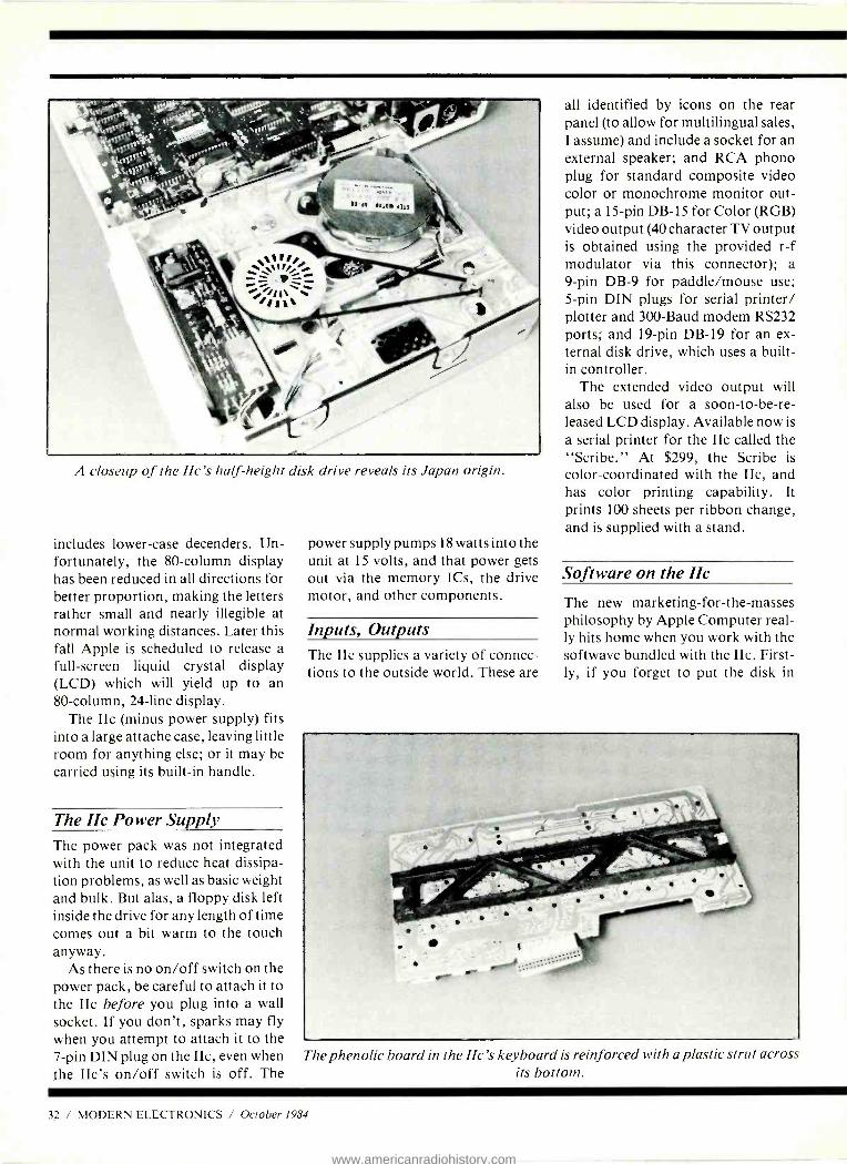
I closeup of the He's half -height disk drive reveals its Japan origin.
includes lower -case decenders. Un- fortunately, the 80- column display has been reduced in all directions for better proportion, making the letters rather small and nearly illegible at normal working distances. Later this fall Apple is scheduled to release a full- screen liquid crystal display (LCD) which will yield up to an 80- column, 24 -line display.
The IIc (minus power supply) fits into a large attache case, leaving little room for anything else; or it may be carried using its built -in handle.
The IIc Power Supply The power pack was not integrated with the unit to reduce heat dissipa- tion problems, as well as basic weight and bulk. But alas, a floppy disk left inside the drive for any length of time comes out a bit warm to the touch anyway.
As there is no on /off switch on the power pack, be careful to attach it to the llc before you plug into a wall socket. If you don't, sparks may fly when you attempt to attach it to the 7 -pin DIN plug on the IIc, even when the IIc's on /off switch is off. The
power supply pumps 18 watts into the unit at 15 volts, and that power gets out via the memory ICs, the drive motor, and other components.
Inputs, Outputs The IIc supplies a variety of connec- tions to the outside world. These are
all identified by icons on the rear panel (to allow for multilingual sales, I assume) and include a socket for an external speaker; and RCA phono plug for standard composite video color or monochrome monitor out- put; a 15 -pin DB -15 for Color (RGB) video output (40 character TV output is obtained using the provided r -f modulator via this connector); a 9 -pin DB -9 for paddle /mouse use; 5 -pin DIN plugs for serial printer/ plotter and 300 -Baud modem RS232 ports; and 19 -pin DB -19 for an ex- ternal disk drive, which uses a built - in controller.
The extended video output will also be used for a soon- to- be -re- leased LCD display. Available now is
a serial printer for the IIc called the "Scribe." At $299, the Scribe is color- coordinated with the IIc, and has color printing capability. It prints 100 sheets per ribbon change, and is supplied with a stand.
Software on the IIc
The new marketing- for -the -masses philosophy by Apple Computer real- ly hits home when you work with the softwave bundled with the IIc. First- ly, if you forget to put the disk in
The phenolic board in the lie's keyboard is reinforced with a plastic strut across its bottom.
32 / MODERN ELECTRONICS / October 1984
www.americanradiohistory.com
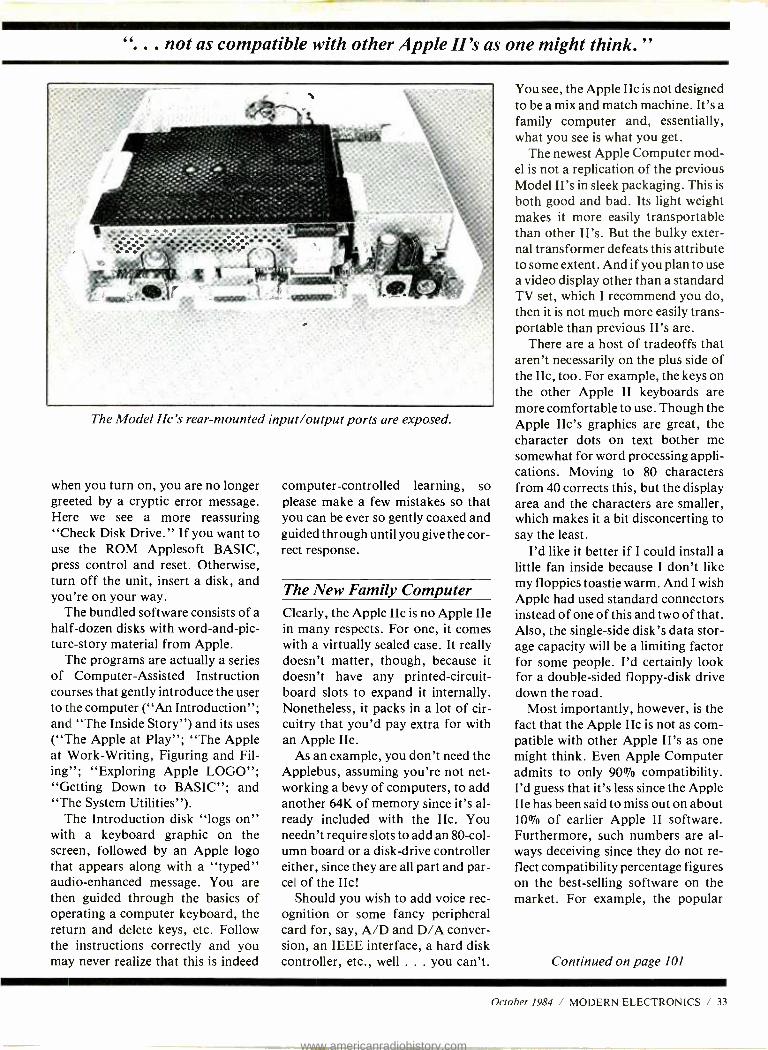
... not as compatible with other Apple II's as one might think."
The Model IIc's rear -mounted input /output ports are exposed.
when you turn on, you are no longer greeted by a cryptic error message. Here we see a more reassuring "Check Disk Drive." If you want to use the ROM Applesoft BASIC, press control and reset. Otherwise, turn off the unit, insert a disk, and you're on your way.
The bundled software consists of a half -dozen disks with word- and -pic- ture -story material from Apple.
The programs are actually a series of Computer- Assisted Instruction courses that gently introduce the user to the computer ( "An Introduction "; and "The Inside Story ") and its uses ( "The Apple at Play "; "The Apple at Work -Writing, Figuring and Fil- ing"; "Exploring Apple LOGO "; "Getting Down to BASIC "; and "The System Utilities ").
The Introduction disk "logs on" with a keyboard graphic on the screen, followed by an Apple logo that appears along with a "typed" audio -enhanced message. You are then guided through the basics of operating a computer keyboard, the return and delete keys, etc. Follow the instructions correctly and you may never realize that this is indeed
computer -controlled learning, so please make a few mistakes so that you can be ever so gently coaxed and guided through until you give the cor- rect response.
The New Family Computer Clearly, the Apple IIc is no Apple IIe in many respects. For one, it comes with a virtually sealed case. It really doesn't matter, though, because it doesn't have any printed- circuit- board slots to expand it internally. Nonetheless, it packs in a lot of cir- cuitry that you'd pay extra for with an Apple IIe.
As an example, you don't need the Applebus, assuming you're not net- working a bevy of computers, to add another 64K of memory since it's al- ready included with the IIc. You needn't require slots to add an 80 -col- umn board or a disk -drive controller either, since they are all part and par- cel of the IIc!
Should you wish to add voice rec- ognition or some fancy peripheral card for, say, A/D and D/A conver- sion, an IEEE interface, a hard disk controller, etc., well ... you can't.
You see, the Apple Iic is not designed to be a mix and match machine. It's a family computer and, essentially, what you see is what you get.
The newest Apple Computer mod- el is not a replication of the previous Model II's in sleek packaging. This is both good and bad. Its light weight makes it more easily transportable than other II's. But the bulky exter- nal transformer defeats this attribute to some extent. And if you plan to use a video display other than a standard TV set, which I recommend you do, then it is not much more easily trans- portable than previous II's are.
There are a host of tradeoffs that aren't necessarily on the plus side of the IIc, too. For example, the keys on the other Apple II keyboards are more comfortable to use. Though the Apple lic's graphics are great, the character dots on text bother me somewhat for word processing appli- cations. Moving to 80 characters from 40 corrects this, but the display area and the characters are smaller, which makes it a bit disconcerting to say the least.
I'd like it better if I could install a little fan inside because I don't like my floppies toastie warm. And I wish Apple had used standard connectors instead of one of this and two of that. Also, the single -side disk's data stor- age capacity will be a limiting factor for some people. I'd certainly look for a double -sided floppy -disk drive down the road.
Most importantly, however, is the fact that the Apple IIc is not as com- patible with other Apple II's as one might think. Even Apple Computer admits to only 90% compatibility. I'd guess that it's less since the Apple IIe has been said to miss out on about 10% of earlier Apple II software. Furthermore, such numbers are al- ways deceiving since they do not re- flect compatibility percentage figures on the best -selling software on the market. For example, the popular
Continued on page 101
October 1984 / MODERN ELECTRONICS / 33
www.americanradiohistory.com

Technology
A New Era of Go- Anywhere Color TV Has Arrived!
New developments in LCD technology bring to market a lightweight color TV receiver you can slip into your pocket
By Alexander W. Burawa
Long awaited, the era of color viewing in a TV receiver small enough to be comfortably car-
ried around in a pocket is finally here! And the surprise is that it is not being manufactured and sold by one of the traditional video giants, but by a company that has made a world- wide name for itself in personal com- puter products. The company is Ep- son America, and the product is the Epson "Elf," a tidy little receiver that offers a 2 "diagonal color picture
in a package that measures only 6.3 "W x 3.15 "H x 1.22 "D and weighs a mere 1.1 lb. Suggested retail price for this nifty little wonder is
about $500, and availability is pro- jected for early October, not long af- ter you read this.
Groundbreaking Technology In designing the Elf pocketable color TV receiver, new design ground in liquid -crystal technology had to be broken. Since traditional LCD panels, like those used in wrist- watches and calculators (see "What
Went Before" box), were not really suited to the action sequences nor- mally encountered in TV programs. The SUWA Seiko -sha Company in Japan, to which Epson belongs, set about designing a fast -responding li- quid crystal. What emerged from the design labs is a marvel in miniaturiza- tion, as shown in an accompanying drawing.
The LCD panel that makes up the display area of the Epson Elf is com- posed of a matrix of thousands of picture elements, known in TV and computer jargon as "pixels," that are selectively turned "on" and
34 / MODERN ELECTRONICS / October 1984
www.americanradiohistory.com

"off" by signals demodulated from the TV broadcast program. There are 52,800 of these pixels, arranged 240 horizontally by 220 vertically. Theor- etically, the display is capable of re- solving 220 lines, which is not as much as is theoretically possible with a standard CRT system but is plenty for the tiny picture displayed on the LCD's 2 -inch diagonal screen.
The twisted nematic liquid crystal material used in the display panel does not in itself have color characteristics. Instead, the display assembly employs color filters to develop the actual col- ors you see when viewing the Elf. Just as there are only red, green, and blue primary colors in the color CRT pic- ture tube, there are only red, green, and blue filters used in the Elf's LCD panel assembly. Technically speak- ing, though the Elf has a total of 52,800 pixels, this figure must be divided by three to take into account the RGB arrangement whose colors are combined to produce any but the three primary colors. The net result is a display consisting of 17,600 color points for displaying full -color pic- tures, which is more than sufficient for the tiny display area.
Images are displayed on the screen area of the LCD panel by light pass- ing through from behind the panel. Hence, the LCD panel is of the trans- missive variety (as opposed to the re- flective variety used in most digital timepieces, calculators, and test in- struments). Light for displaying viewable pictures on the screen of the Epson Elf can come from either of two sources. For indoor viewing, where light is usually subdued or lights are turned out altogether, the Elf has a built -in user -replaceable fluorescent lamp that backlights the display area. Outdoor viewing uses natural sunlight as the light source. When viewing outdoors, the internal fluorescent lamp is disabled and the receiver's rear panel is swung open to permit entry of light. The stronger the light, the more brillant the colors and the better the picture.
The lattice structure of the nematic liquid crystal used in the Epson Elf's
LCD panel is designed so that it twists into a helix -like spiral when an electrical charge is applied between the two electrodes that back and face the material. When the material is at rest -that is, no electrical potential is applied across it -the liquid crystal material is twisted into a helix -like spiral that orients the light passing through to permit maximum bright- ness when the LCD panel is viewed from the front. Applying an increas- ing potential to the electrodes causes the material to untwist and allow less and less light to pass, until at maxi- mum potential the amount of light
getting through is, for all practical purposes, nil and that particular pix- el's color does not enter into forming of the picture on the screen.
Until last year, nematic liquid cry- stals were relatively slow to respond to electrical signals applied to them. This limited their efficiency as a medium for displaying action video pictures, and only passable -quality monochrome TV receivers were avail- able using this technology. With Seiko's new fast -responding LCD panel, much of the difficulty has been countered. The LCD panel used in the Elf responds twice as fast to
Epson E f
LCD circuit board Thin film transistor
Gloss Output Liquid Common electrode crystal electrode
Polarize
Enlarged portion of screen
Colored filters
Glass Polar¢er
Red filter
Green filter
Details of the seven layers that make up the elf's LCD panel arrangement are shown upper right. Remainder of drawing shows progressively larger magnifica-
tions of the matrix arrangement of pixels in the matrix.
October 1984 / MODERN ELECTRONICS / 35
www.americanradiohistory.com
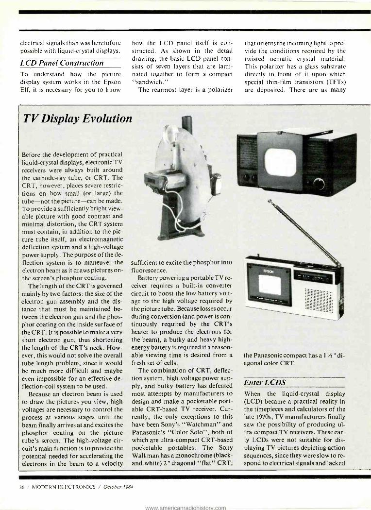
electrical signals than was heretofore possible with liquid- crystal displays.
LCD Panel Construction To understand how the picture display system works in the Epson Elf, it is necessary for you to know
how the LCD panel itself is con- structed. As shown in the detail drawing, the basic LCD panel con- sists of seven layers that are lami- nated together to form a compact "sandwich."
The rearmost layer is a polarizer
that orients the incoming light to pro- vide the conditions required by the twisted nematic crystal material. This polarizer has a glass substrate directly in front of it upon which special thin -film transistors (TFTs) are deposited. There are as many
TV Display Evolution
Before the development of practical liquid- crystal displays, electronic TV receivers were always built around the cathode -ray tube, or CRT. The CRT, however, places severe restric- tions on how small (or large) the tube -not the picture -can be made. To provide a sufficiently bright view- able picture with good contrast and minimal distortion, the CRT system must contain, in addition to the pic- ture tube itself, an electromagnetic deflection system and a high -voltage power supply. The purpose of the de- flection system is to maneuver the electron beam as it draws pictures on- the screen's phosphor coating.
The length of the CRT is governed mainly by two factors: the size of the electron gun assembly and the dis- tance that must be maintained be- tween the electron gun and the phos- phor coating on the inside surface of the CRT. It is possible to make a very short electron gun, thus shortening the length of the CRT's neck. How- ever, this would not solve the overall tube length problem, since it would be much more difficult and maybe even impossible for an effective de- flection -coil system to be used.
Because an electron beam is used to draw the pictures you view, high voltages are necessary to control the process at various stages until the beam finally arrives at and excites the phosphor coating on the picture tube's screen. The high -voltage cir- cuit's main function is to provide the potential needed for accelerating the electrons in the beam to a velocity
sufficient to excite the phosphor into fluorescence.
Battery powering a portable TV re- ceiver requires a built -in converter circuit to boost the low battery volt- age to the high voltage required by the picture tube. Because losses occur during conversion (and power is con- tinuously required by the CRT's heater to produce the electrons for the beam), a bulky and heavy high - energy battery is required if a reason- able viewing time is desired from a fresh set of cells.
The combination of CRT, deflec- tion system, high -voltage power sup- ply, and bulky battery has defeated most attempts by manufacturers to design and make a pocketable port- able CRT -based TV receiver. Cur- rently, the only exceptions to this have been Sony's "Watchman" and Panasonic's "Color Solo ", both of which are ultra- compact CRT -based pocketable portables. The Sony Walkman has a monochrome (black - and- white) 2" diagonal "flat" CRT;
the Panasonic compact has a 1'h "di- agonal color CRT.
Enter LCDS When the liquid -crystal display (LCD) became a practical reality in the timepieces and calculators of the late 1970s, TV manufacturers finally saw the possibility of producing ul- tra- compact TV receivers. These ear- ly LCDs were not suitable for dis- playing TV pictures depicting action sequences, since they were slow to re- spond to electrical signals and lacked
36 / MODERN ELECTRONICS / October 1984
www.americanradiohistory.com
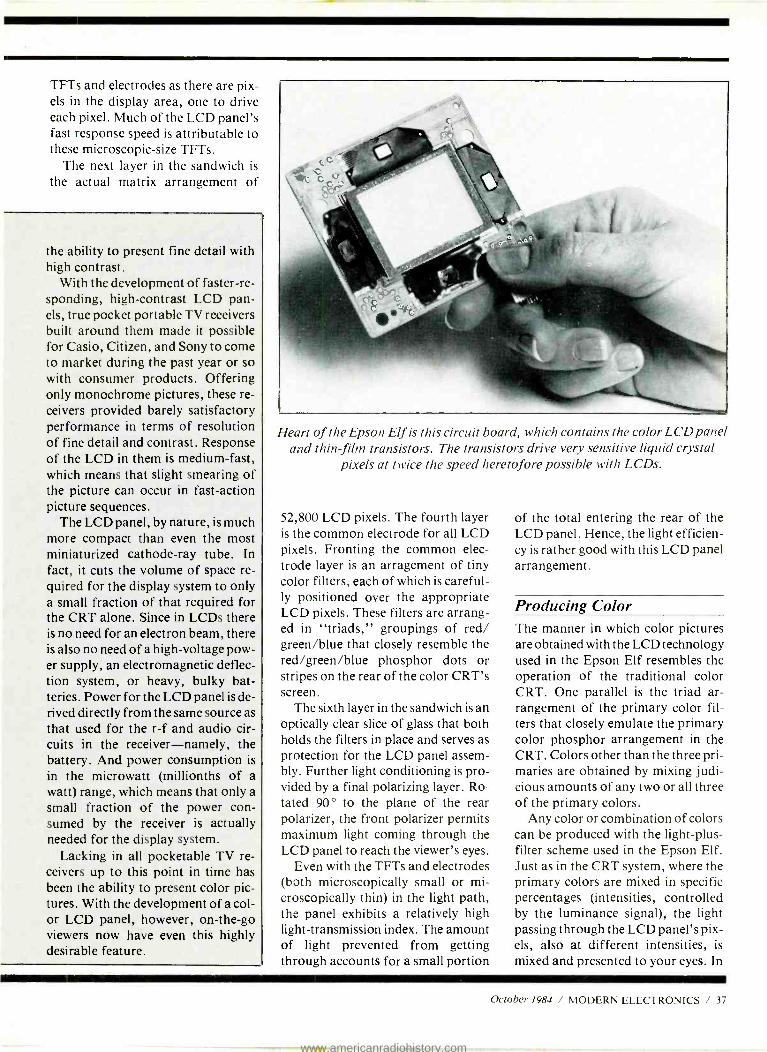
TFTs and electrodes as there are pix- els in the display area, one to drive each pixel. Much of the LCD panel's fast response speed is attributable to these microscopic -size TFTs.
The next layer in the sandwich is
the actual matrix arrangement of
the ability to present fine detail with high contrast.
With the development of faster -re- sponding, high- contrast LCD pan- els, true pocket portable TV receivers built around them made it possible for Casio, Citizen, and Sony to come to market during the past year or so with consumer products. Offering only monochrome pictures, these re- ceivers provided barely satisfactory performance in terms of resolution of fine detail and contrast. Response of the LCD in them is medium -fast, which means that slight smearing of the picture can occur in fast -action picture sequences.
The LCD panel, by nature, is much more compact than even the most miniaturized cathode -ray tube. In fact, it cuts the volume of space re- quired for the display system to only a small fraction of that required for the CRT alone. Since in LCDs there is no need for an electron beam, there is also no need of a high -voltage pow- er supply, an electromagnetic deflec- tion system, or heavy, bulky bat- teries. Power for the LCD panel is de- rived directly from the same source as that used for the r -f and audio cir- cuits in the receiver- namely, the battery. And power consumption is in the microwatt (millionths of a watt) range, which means that only a small fraction of the power con- sumed by the receiver is actually needed for the display system.
Lacking in all pocketable TV re- ceivers up to this point in time has been the ability to present color pic- tures. With the development of a col- or LCD panel, however, on- the -go viewers now have even this highly desirable feature.
Heart of the Epson Elf is this circuit board, which contains the color LCD panel and thin-film transistors. The transistors drive very sensitive liquid crystal
pixels at twice the speed heretofore possible with LCDs.
52,800 LCD pixels. The fourth layer is the common electrode for all LCD pixels. Fronting the common elec- trode layer is an arragement of tiny color filters, each of which is careful- ly positioned over the appropriate LCD pixels. These filters are arrang- ed in "triads," groupings of red/ green /blue that closely resemble the red /green /blue phosphor dots or stripes on the rear of the color CRT's screen.
The sixth layer in the sandwich is an optically clear slice of glass that both holds the filters in place and serves as protection for the LCD panel assem- bly. Further light conditioning is pro- vided by a final polarizing layer. Ro- tated 90 ° to the plane of the rear polarizer, the front polarizer permits maximum light coming through the LCD panel to reach the viewer's eyes.
Even with the TFTs and electrodes (both microscopically small or mi- croscopically thin) in the light path, the panel exhibits a relatively high light- transmission index. The amount of light prevented from getting through accounts for a small portion
of the total entering the rear of the LCD panel. Hence, the light efficien- cy is rather good with this LCD panel arrangement.
Producing Color The manner in which color pictures are obtained with the LCD technology used in the Epson Elf resembles the operation of the traditional color CRT. One parallel is the triad ar- rangement of the primary color fil- ters that closely emulate the primary color phosphor arrangement in the CRT. Colors other than the three pri- maries are obtained by mixing judi- cious amounts of any two or all three of the primary colors.
Any color or combination of colors can be produced with the light -plus- filter scheme used in the Epson Elf. Just as in the CRT system, where the primary colors are mixed in specific percentages (intensities, controlled by the luminance signal), the light passing through the LCD panel's pix- els, also at different intensities, is
mixed and presented to your eyes. In
October 1984 / MODERN ELECTRONICS / 37
www.americanradiohistory.com
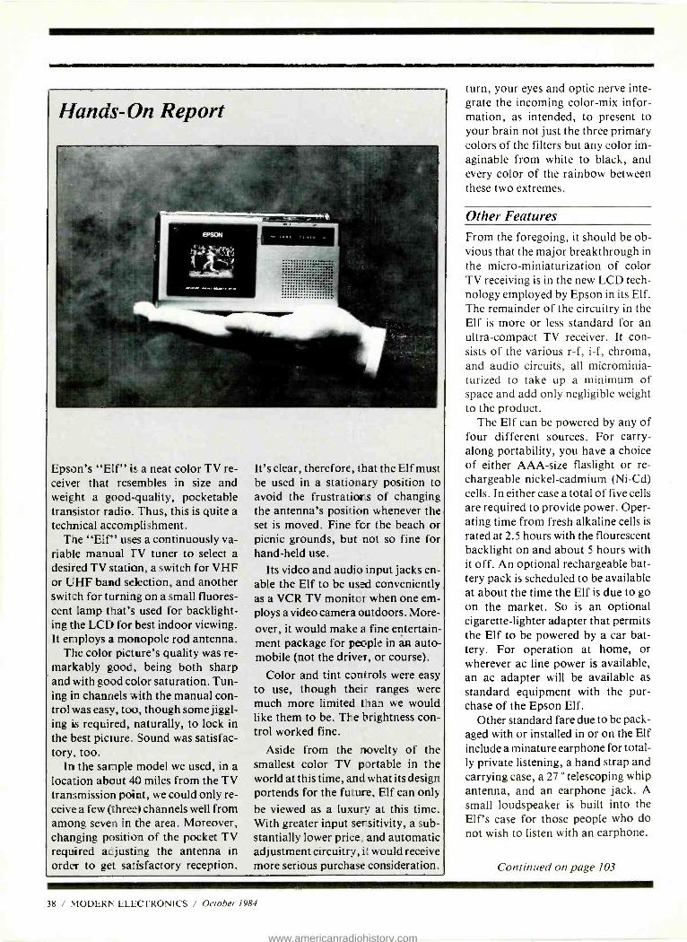
Hands -On Report
Epson's "Elf" is a neat color TV re- ceiver that resembles in size and weight a good- quality, pocketable transistor radio. Thus, this is quite a technical accomplishment.
The "Elf" uses a continuously va- riable manual TV tuner to select a desired TV station, a switch for VHF or UHF band selection, and another switch for turning on a small fluores- cent lamp that's used for backlight- ing the LCD for best indoor viewing. It employs a monopole rod antenna.
The color picture's quality was re- markably good, being both sharp and with good color saturation. Tun- ing in channels with the manual con- trol was easy, too, though some jiggl- ing is required, naturally, to lock in the best picture. Sound was satisfac- tory, too.
In the sample model we used, in a location about 40 miles from the TV transmission point, we could only re- ceive a few (three) channels well from among seven in the area. Moreover, changing position of the pocket TV required adjusting the antenna in order to get satisfactory reception.
It's clear, therefore, that the Elf must be used in a stationary position to avoid the frustrations of changing the antenna's position whenever the set is moved. Fine for the beach or picnic grounds, but not so fine for hand -held use.
Its video and audio input jacks en -
able the Elf to be used conveniently as a VCR TV monitor when one em- ploys a video camera outdoors. More- over, it would make a fine entertain- ment package for people in an auto- mobile (not the driver, or course).
Color and tint controls were easy to use, though their ranges were much more limited than we would like them to be. The brightness con- trol worked fine.
Aside from the novelty of the smallest color TV portable in the world at this time, and what its design portends for the future, Elf can only
be viewed as a luxury at this time. With greater input sensitivity, a sub- stantially lower price, and automatic adjustment circuitry, it would receive more serious purchase consideration.
turn, your eyes and optic nerve inte- grate the incoming color -mix infor- mation, as intended, to present to your brain not just the three primary colors of the filters but any color im- aginable from white to black, and every color of the rainbow between these two extremes.
Other Features From the foregoing, it should be ob- vious that the major breakthrough in the micro -miniaturization of color TV receiving is in the new LCD tech- nology employed by Epson in its Elf. The remainder of the circuitry in the Elf is more or less standard for an ultra- compact TV receiver. It con- sists of the various r -f, i -f, chroma, and audio circuits, all microminia- turized to take up a minimum of space and add only negligible weight to the product.
The Elf can be powered by any of four different sources. For carry - along portability, you have a choice of either AAA -size flaslight or re- chargeable nickel- cadmium (Ni -Cd) cells. In either case a total of five cells are required to provide power. Oper- ating time from fresh alkaline cells is
rated at 2.5 hours with the flourescent backlight on and about 5 hours with it off. An optional rechargeable bat- tery pack is scheduled to be available at about the time the Elf is due to go on the market. So is an optional cigarette- lighter adapter that permits the Elf to be powered by a car bat- tery. For operation at home, or wherever ac line power is available, an ac adapter will be available as standard equipment with the pur- chase of the Epson Elf.
Other standard fare due to be pack- aged with or installed in or on the Elf include a minature earphone for total- ly private listening, a hand strap and carrying case, a 27 " telescoping whip antenna, and an earphone jack. A small loudspeaker is built into the Elf's case for those people who do not wish to listen with an earphone.
Continued on page 103
38 / MODERN ELECTRONICS / October 1984
www.americanradiohistory.com

EXPAND YO
' -irr- ;7 IME--ANIM_ --_ _ --
START WITH CIE. Microprocessor Technology. Satellite Communications. Robotics. Wherever you want to go in electronics
start first with CIE. Why CIE? Because we're the leader in :eaching
electronics through independent study. Consider this. We teach over 25,000 students from all over the United States and in over 70 foreign countries. And we've been doing it for over 50 years, helping thou- sands of men and women get started in electronics careers.
We offer flexible training to meet your needs. You can start at the beginner level or, if you already know something about electronics, you may want to start at a higher level. But wherever you start, you can go as far as you like. You can even earn your Associate in Applied Science Degree in Electronics.
CIRCLE 36 ON FREE INFORMATION CARD
r
The CIE Microprocessor Trainer helps you to learn how circuits with microprocessors function in computers.
Let us get you started today. Just call toll -free 1- 800 -321 -2155 (in Ohio, 1-800-362-2105) or mail in the handy coupon.
ED3Cleveland Institute of Electronics 1776 East 17th St., Cleveland, Ohio 44114
YES. .1 want to get started! Send me my FREE CIE school catalog . including details about the Associate Degree program ... plus my FREE package of home study information.
Print Name
Address Apt.
City State Zip
Age Area Code /Phone No.
Check box for G.I. Bill bulletin on Education Benefits Veteran Active Duty
MAIL TODAY! MO-20
www.americanradiohistory.com
d PHILIPS KEITHLEY WESTON Non -Linear Systems LEADER
77 0.3% Accuracy Manual or Autorange
10A + mA Range Beeper
"Touch- Hold" Function
41/2 DIGIT
MULTIMETERS
' , MODEL 8060A
$349 00
+1( PRf ClSION
$1290°
WE CARRY A FULL LINE OF FLUKE MULTI -METERS. IN STOCK NOW
FLUKE Frequency measuements to 200KHz dB measurements Basic dc accuracy 0.4 %; 10µV, 10 nA and 10 mir sensitivity Relative measurements True RMS High-speed Beeper
POWER SUPPLIES
529995 M 601 ODEL
Isolated 0.50VDC, continuously variable; 0-2A in four ranges Fully automatic shutdown, adjustable current limit Perfect for solid state servicing
$32995 MODEL 1650
Functions as three separate supplies Exclusive tracking circuit Fixed output 5VDC, 5A Two 0 to 25VDC outputs at 0.5A Fully automatic, current -limited overload protection
FUNCTION GENERATORS
$31995
Sine, square and triangle output Variable and fixed TTL outputs 0.1 Hz to 1MHz in six ranges Push button range and function selection Typical sine wave distortion under 0.5% from 1 Hz to 100kHz
MODEL 3020
SWEEP FUNCTION Four instruments in one package - sweep generator, function generator, pulse generator, tone - burst generator Covers 0.02Hz -2MHz 1000:1 tuning range Low -distortion high- accuracy outputs
FLUKE SERIES MULTIMETERS
Analog Display Rotary Knob Volts AC & DC Resistance to 32 Mfl 10 Amps Diode Test 3200 Counts Fast Autoranging Function Annunciators in Display Power -Up Self Test
2000+ Hour Battery Life w/ Power Down "Sleep Mode" New Test Leads VDE & UL Approval
0.5% Accuracy Manual or Autorange 10A + 300 mA Range Beeper
:4K PRE CIS/ON INDUSTRIAL
TRANSISTOR TESTER
$19995
MODEL 5208
Now with HI /LO Drive
Works in- circuit when others won't Identifies all three tran- sistor leads
Random lead connection Audibly and visually in- dicates GOOD transistor
MODEL 830
$8500
73 ---ter
0.7% Accuracy Autorange Only 10 Amp Only
70 MHz Dual Time Base SCOPE MODEL
1570
PRICE DOES NOT
INCLUDE PROBES
lmV /division sensitivity to 70 MHz 500 µ V /division cascade sensitivity Four -input operation provides trigger view on 4 separate inputs Alternate time base operation Switching power supply delivers best efficiency and regulation at lowest weight
CAPACITANCE METERS
519995 $15995
Automatically mea- sures capacitance from 0.1 pF to 200mF
0.1pF resolution 0.2% basic accuracy 31/2 digit LCD display
MODEL 820
Resolves to 0.1 pF
4 digit easy -to -read LED display Fuse protected against charged capacitors Overrange indication
www.americanradiohistory.com
*HITACHI PATA PRECISION TRIPLETT
FLUKE rAtS ()CRC HICKOK VI Z wòw
r..,ry _ ; U.,,
V222
HI- PERFORMANCE PORTABLE OSCILLOSCOPES ALL FEATURE 6" RECTANGULAR CRT Full 2 year parts & labor warranty.
HITACHI
V -422 DC to 40 MHz, 1 mV /div, dual- trace, DC offset function
$599 95
V-222 449 9 95
DC to 20 MHz, 1 mV /div, dual- trace, DC off. func., Alt. magnify function
'439 5 V-212 DC to 20 MHz, 1mV /div, dual -trace
BECKMAN'S CIRCUITMATE ALL UNDER $100 AVAILABLE NOW.. .
$64" Circuitmate DM 20- 31/2 -digit, pocket -size multimeter; 0.8% Vdc accuracy, diode test,
FE test, conductance, 10 amps AC and DC
ranges, auto -polarity auto -zero, auto -
decimal
$79" Circuitmate DM-25- 31/2 digit, pocket -size multimeter; 0.5% Vac accuracy, diode test,
apacitance, continuity beeper, conductance,
10 amps AC and DC ranges, auto -polarity,
auto -zero, auto - decimal
$69" Circuitmate DM -40 - 3' /z -digit multimeter; 0.8% Vdc accuracy,
diode test, auto - polarity, auto -zero,
auto- decimal
TOLL FREE HOT LINE
$8995 Circuitmate DM 45 -
31/2-digit multimeter; 0.5% Vdc accuracy,
diode test,continuity beeper, 10 amps AC
and DC ranges, auto - zero, auto -polarity,
auto -decimal
w.
V-1050
$1,249 95
V -1050F 100 MHz Quad Trace w /delay sweep
V -650F 939 95
60 MHz Dual Trace w /delay sweep
PRICE DOES NOT INCLUDE PROBES. PROBES $50. A PAIR WHEN PURCHASED WITH SCOPE $15 SHIPPING WITHIN CONTINENTAL U.S.
The DM73 is the smallest digital multimeter on the market. Its
probe -style design makes it ideal for taking measurements in hard -
to-reach test areas.
s63 ss
$76" The DM 77 gives you
the convenience of autoranging plus 10
amps ac /dc measurement
capability. You simply select the function you want, and the
DM 77 automatically sets the required
range.
Small Size Complete Autoranging
"Touch Hold' Audible continuity checking
800 -223 -0474 THE TEST EQUIPMENT SPECIALISTS aval_V
26 WEST 46th STREET. NEW YORK, N.Y. 100:6 ELECTRONIC 212- 730 -7030
CIRCLE 38 ON FREE INFORMATION CARD
www.americanradiohistory.com

How To Get Started In Electronics
Part I: Inside Semiconductors
By Forrest M. Mims III
The material for this article is extracted from the author's book Getting Started in Electron- ics, published by Radio Shack. Copyright 1983
by Forrest M. Mims III.
Flectronics experimenting is re- warding, and challenging.
J There are few other pursuits that are more satisfying, especially when you finish building a project, turn it on, and find you've created from a meaningless pile of compon- ents something really useful. Thus, you've become a creator with an end - product to show for your efforts.
Electronics experimenters often have different objectives. You might wish to simply convert an idea for a circuit into a finished project just for the fun of seeing it take shape and op- erate as you designed it to do. Or you might have a need for a device that isn't available commercially, or you might want to make something that is
available commercially but you feel you can build at lower cost.
Whatever your reasons for want- ing to build projects or experiment with your own circuit ideas, you'll need some idea of how to use the various elements available to create practical circuits. To be able to do this, you must understand how these devices work and how they interact.
As the title of this series implies, the objective of this series is to in- troduce you to these elements star- ting with semiconductors.
Silicon Recipes There are many different semicon- ducting materials, but silicon, the
main ingredient of sand, is the most popular ingredient.
A silicon atom has only four elec- trons in its outermost shell, but it would like to have eight. Therefore, a silicon atom will link up with four of its neighbors to share electrons as follows:
A cluster of silicon atoms sharing outer electrons forms a regular ar- rangement called a crystal. To keep things simple, in the above drawing of a silicon crystal, only the outer electrons are shown.
Pure silicon isn't very useful. That's why silicon makers spice up their silicon recipes with a dash of phosphorous, boron, or other goodies. This is called "doping" the silicon. Then silicon has very useful electrical properties indeed!
PandN Spiced Loaf.. Boron, phos- phorous, and certain other atoms can join with silicon atoms to form crys- tals. Here's the catch: A boron atom has only three electrons in its outer shell, while a phosphorus atoms has five electrons. Silicon with extra phosphorus electrons is called n -type silicon (n = negative). Silicon with electron- deficient boron atoms is called p -type (p= positive) silicon.
P -type Silicon. A boron atom in a cluster of silicon atoms leaves a va- cant electron opening called a "hole." It's possible for an electron from a nearby atom to "fall" into the hole. Therefore, the hole has moved to a new location. Remember, holes can move through silicon (just as bubbles move through water).
N -Type Silicon. A phosphorus atom in a cluster of silicon atoms do- nates an extra electron that can move through the crystal with comparative
44 / MODERN ELECTRONICS / October 1984
www.americanradiohistory.com

ease. In other words, n -type silicon can carry an electrical current. But so can p -type silicon! Holes are what "carry" the current.
The Diode Both n- and p -type silicon conduct electricity. The resistance of both types is determined by the proportion of holes or surplus electrons. There- fore, both types can function as resis- tors. And they will conduct electrici- ty in any direction.
By forming somep -type silicon in a chip of n -type silicon, electrons will flow through the silicon in only one direction. This is the principle of the diode. The p -n interface is called the pn junction.
How the Diode Works Here's a simplified explanation of how a diode conducts electricity in one direction (forward) while block- ing the flow of current in the opposite direction (reverse).
REVERSE LIA S
N P
0 o oo
NO CuRRENr ri_ow
In A, the charge from the battery repels holes and electrons toward the junction. If the voltage exceeds 0.6 volt (silicon), electrons will cross the junction and combine with holes, allowing a current to flow.
In B, the charge from the battery attracts holes and electrons away from the junction. Under this condi- tion, no current can flow.
Diodes are commonly enclosed in small glass cylinders. A dark band around one end of the cylinder identi-
EHEN ANOOE IS
MORE P051TivE THAN CATHODE.
fies the cathode terminal. The op- posite terminal is the anode. The above drawing illustrates both the physical packaging of the diode and its schematic symbol.
You already know from the fore- going discussion that a diode is like an electronic one -way valve. It's im- portant to understand some addi- tional aspects of diode operation. Here are some key ones:
1. A diode will not conduct until the forward voltage reaches a certain threshold point. For silicon diodes, this is about 0.6 volt.
2. If the forward current becomes excessive, the semiconductor chip may crack or melt! And the contacts may separate. If the chip melts, the diode may suddenly conduct in both directions. The resulting heat may vaporize the chip!
3. Too much reverse voltage will cause a diode to conduct in the wrong direction. Since this voltage is fairly high, the sudden current surge may zap the diode.
Diode Types & Uses
Many different kinds of diodes are
available. Here are some of the major types in common usage:
Small Signal. These diodes trans- form low- current ac to dc, detect (de- modulate) radio signals, multiply voltage, perform logic operation, ab- sorb voltage spikes, etc.
Power Rectifier. Functionally identical to small -signal diodes, pow- er rectifiers can handle much more current. They are installed in large metal packages that soak up excess heat and transfer it to a metal heat sink. They are used mainly in power supplies.
Zener Diode. This specialty rectifi- er is designed to have a specific re- verse breakdown (conduction) volt- age. This means zener diodes can function like a voltage- sensitive switch. Zener diodes having break- down voltages (Vz of from 2 to 200 volts are available.
Light -Emitting Diode. All diodes emit some electromagnetic radiation when forward baised. Diodes made from certain semiconductors (like gallium arsenide phosphide) emit considerably more radiation than silicon diodes. They're called light - emitting diodes (LEDs).
Photodiode. All diodes also re- spond to some degree when illumin- ated by light. Diodes designed speci- fically to detect light are called photodiodes. They include a glass or plastic window through which the light enters. Often they have a large, exposed junction region. Silicon makes good photodiodes.
Various types of diodes are used in many applications. For now, here are two of the most important roles for small -signal diodes and rectifiers:
The first is a single -wave rectifier circuit in which an undulating (ac) signal or voltage is rectified into a single -polarity (dc) signal or voltage.
The second is the full -wave rec- tifier circuit in which a four -diode "network" (or bridge rectifier) rec- tifies both halves of an ac signal.
Note the difference in output from the two circuits. In the half -wave cir- cuit only one alternation of the input generates an output, while both alter-
October 1984 / MODERN ELECTRONICS / 45
www.americanradiohistory.com
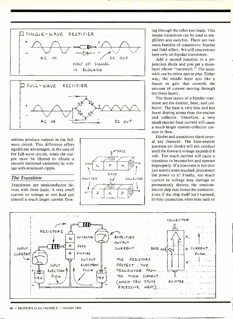
SINGLE - WAVE fZECTII`IER
c==( {4=.
AC IN Dc 'ouT HALF oF SIGNAL
IS BLOCKED
FULL- WAVE RECTIFIER
AC IN DC. CuT
nations produce outputs in the full - wave circuit. This difference offers significant advantages, in the case of the full -wave circuit, when the out- put must be filtered to obtain a smooth (minimal- variation) dc volt- age with minimum ripple.
The Transistor Transistors are semiconductor de- vices with three leads. A very small current or voltage at one lead can control a much larger current flow-
ing through the other two leads. This means transistors can be used as am- plifiers and switches. There are two main families of transistors: bipolar and field- effect. We will concentrate here only on bipolar transistors.
Add a second junction to a pn- junction diode and you get a three - layer silicon "sandwich." The sand- wich can be either npn or pnp. Either way, the middle layer acts like a faucet or gate that controls the amount of current moving through the three layers.
The three layers of a bipolar tran- sistor are the emitter, base, and col- lector. The base is very thin and has fewer doping atoms than the emitter and collector. Therefore, a very small emitter -base current will cause a much larger emitter -collector cur- rent to flow.
Diodes and transistors share sever- al key features: The base -emitter junction (or diode) will not conduct until the forward voltage exceeds 0.6 volt. Too much current will cause a transistor to become hot and operate improperly. If a transistor is hot (not just warm) when touched, disconnect the power to it! Finally, too much current or voltage may damage or permanently destroy the semicon- ductor chip that forms the transistor. Even if the chip itself isn't harmed, its tiny connection wires may melt or
INPUT
CuRKENr
RES STO RS LTh AfrIPLI PIED
OUT PUT
CuRREto BASE
THE REStsrogs PRorEcr THE TRRJJS1Sro &. FROM
TOO _ h+ucri CVRRENI.
(WHICH CAN CAUSE
aXCE.SSIvE NEAT)
Cou_ EcrOR
Et-11T TER.
p CURRENT
PLOW
N
46 / MODERN ELECTRONICS / October 1984
www.americanradiohistory.com
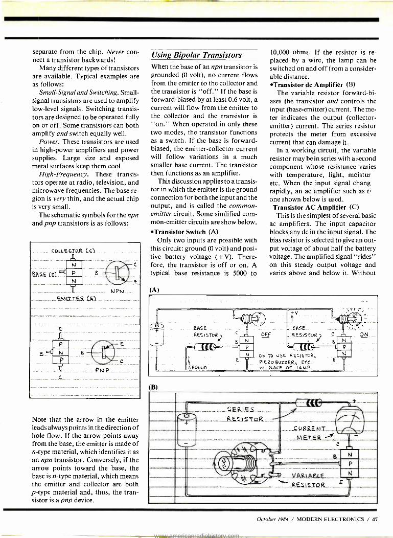
separate from the chip. Never con- nect a transistor backwards!
Many different types of transistors are available. Typical examples are as follows:
Small- Signal and Switching. Small - signal transistors are used to amplify low -level signals. Switching transis- tors are designed to be operated fully on or off. Some transistors can both amplify and switch equally well.
Power. These transistors are used in high -power amplifiers and power supplies. Large size and exposed metal surfaces keep them cool.
High- Frequency. These transis- tors operate at radio, television, and microwave frequencies. The base re- gion is very thin, and the actual chip is very small.
The schematic symbols for the npn and pnp transistors is as follows:
_ .COLLesI9_R LCI.
FIASEí61
C
TE.K LEI
Note that the arrow in the emitter leads always points in the direction of hole flow. If the arrow points away from the base, the emitter is made of n -type material, which identifies it as an npn transistor. Conversely, if the arrow points toward the base, the base is n -type material, which means the emitter and collector are both p -type material and, thus, the tran- sistor is a pnp device.
Using Bipolar Transistors When the base of an npn transistor is grounded (0 volt), no current flows from the emitter to the collector and the transistor is "off." If the base is forward- biased by at least 0.6 volt, a current will flow from the emitter to the collector and the transistor is
"on." When operated in only these two modes, the transistor functions as a switch. If the base is forward - biased, the emitter -collector current will follow variations in a much smaller base current. The transistor then functions as an amplifier.
This discussion applies to a transis- tor in which the emitter is the ground connection for both the input and the output, and is called the common - emitter circuit. Some simlified com- mon- emitter circuits are show below.
*Transistor Switch (A) Only two inputs are possible with
this circuit: ground (0 volt) and posi- tive battery voltage (+ V). There- fore, the transistor is off or on. A typical base resistance is 5000 to
(A)
10,000 ohms. If the resistor is re- placed by a wire, the lamp can be switched on and off from a consider- able distance. *Transistor dc Amplifier (B)
The variable resistor forward -bi- ases the transistor and controls the input (base- emitter) current. The me- ter indicates the output (collector - emitter) current. The series resistor protects the meter from excessive current that can damage it.
In a working circuit, the variable resistor may be in series with a second component whose resistance varies with temperature, light, moistur etc. When the input signal chang rapidly, an ac amplifier such as 0 one shown below is used. Transistor AC Amplifier (C) This is the simplest of several basic
ac amplifiers. The input capacitor blocks any dc in the input signal. The bias resistor is selected to give an out- put voltage of about half the battery voltage. The amplified signal "rides" on this steady output voltage and varies above and below it. Without
- EASE RES ISToR -
. r
1, E
031
GRODUD
BASE _ --- RESISTOR } Ç.
g
\rt
(Illl r
,
P - OK TO V5E RESI.STOR, N
PiEZoguZzER, ETC. E. IN PLACE OF LAMP.
ON
(B)
1
E1 r r S. (
...RRE.NtT ..iZ... ME,TERA 1 -
L. C fr' ' VARAFLF N
-.--- E RES Is7QR._
October 1984 / MODERN ELECTRONICS / 47
www.americanradiohistory.com
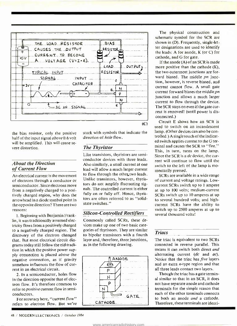
1 __.'AiE..___I,OA.R.__g.ES 1 STOR.._-_... _. u T H F TPu T ß)A.S.._._ ! RtSIS : ,s
IN I l.oAU_
._,.._
._
_._ I I 10
.CAUSES ,_-Q
çuRRE uIS__ IO__ BEc oM F . vaLz..ACZE. (V=ixR.1.- Ill
OUT PUT_}
L 1 A.. J(sl.PIJS_ RESI STQB
--.
.Ef
I SiolAl*. lA1PuT
i
CAPAC.tTQR I
Il
I q
` P
_1)L..-Irai__.51GNAL_ _ .-_.__-___..E. _,__.._.
the bias resistor, only the positive half of the input signal above 0.6 volt will be amplified. This will cause se- vere distortion.
About the Direction of Current Flow An electrical current is the movement of electrons through a conductor or semiconductor. Since electrons move from a negatively charged to a posi- tively charged region, why does the arrowhead in a diode symbol point in the opposite direction? There are two reasons:
1. Beginning with Benjamin Frank- lin, it was traditionally assumed elec- tricity flows from a positively charged to a negatively charged region. The discovery of the electron changed that. But most electrical circuit dia- grams today still follow the old tradi- tion in which the positive power sup- ply connection is placed above the negative connection, as if gravity somehow influences the flow of cur- rent in an electrical circuit.
2. In a semiconductor, holes flow in the direction opposite that of elec- tron flow. It's therefore common to refer to positive current flow in semi- conductors.
For accuracy here, "current flow" refers to electron flow. But we're
(C)
stuck with symbols that indicate the direction of hole flow.
The Thyristor Like transistors, thyristors are semi- conductor devices with three leads. Also similarly, a small current at one lead will allow a much larger current to flow through the othe ;two leads. Unlike transistors, however, thyris- tors do not amplify fluctuating sig- nals. The controlled current is either fully on or fully off. Hence, thyris- tors are often referred to as "solid - state switches."
Silicon- Controlled Rectifiers Commonly called SCRs, these de- vices make up one of two basic cate- gories of thyristors. They are similar to bipolar transistors with a fourth layer and, therefore, three junctions, as in the following drawing.
The physical construction and schematic symbol for the SCR are shown in (D). Frequently, single -let- ter designations are used to identify the leads: A for anode, K (or C) for cathode, and G for gate.
If the anode (A) of an SCR is made more positive than the cathode (K), the two outermost junctions are for- ward biased. The middle pn junc- tion, however, is reverse biased, and current cannot flow. A small gate current forward biases the middle pn junction and allows a much larger current to flow through the device. The SCR stays on even if the gate cur- rent is removed! (until power is dis- connected.)
Circuit E shows how an SCR is
used to switch on an incandescent lamp. (Other devices can also be con- trolled.) A single touch of the indicat- ed switch applies current to the G ter- minal and causes the SCR to "fire." This, in turn, turns on the lamp. Since the SCR is a dc device, the cur- rent will continue to flow until the switch to the left of the lamp is mo- mentarily pressed.
SCRs are available in a wide range of current and voltage ratings. Low - current SCRs switch up to 1 ampere at up to 100 volts; medium- current SCRs switch up to 10 amperes at up to several hundred volts; and high - current SCRs have the ability to switch up to 2500 amperes at up to several thousand volts!
Triacs The triac is equivalent to two SCRs connected in reverse parallel. This means it can switch both direct and alternating current (dc and ac). Notice that the triac has five layers and an extra n -type region and that all three leads contact two layers.
Though the triac has a gate termin- al similar to that in an SCR, it does not have separate anode and cathode terminals for the simple reason that each of the other terminals connects to both an anode and a cathode. Therefore, these terminals are identi-
48 / MODERN ELECTRONICS / October 1984
www.americanradiohistory.com
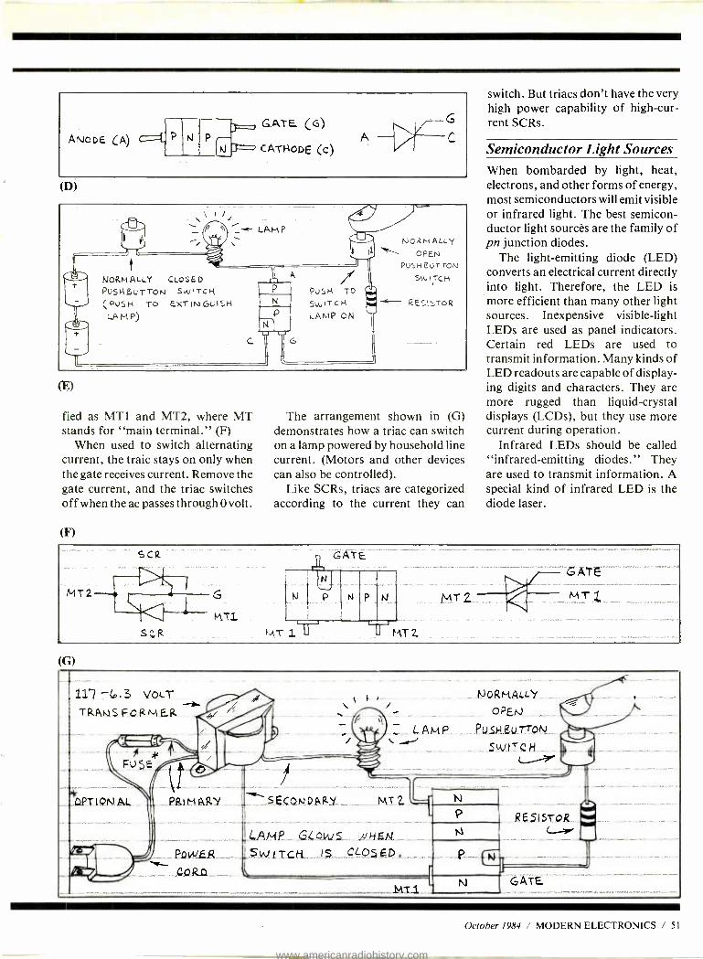
AN- NODE (A) 11111=.11 P --_.. - GATE (G)
CATHODE (c) C
(D)
1
1/411-1r
NORMA4.LY CLQSED PuSHBurrON Sw TCI{ (PUSH To EXTINGUISH
L.A M P)
N
N
PUSH TO
SWITCH LAMP ON
NORM ALLst
OPEN PUSH UT TOIU
SWITCH - RESI5TOR
(E)
fied as MT1 and MT2, where MT stands for "main terminal." (F)
When used to switch alternating current, the traic stays on only when the gate receives current. Remove the gate current, and the triac switches off when the ac passes through 0 volt.
(F)
The arrangement shown in (G) demonstrates how a triac can switch on a lamp powered by household line current. (Motors and other devices can also be controlled).
Like SCRs, triacs are categorized according to the current they can
switch. But triacs don't have the very high power capability of high -cur- rent SCRs.
Semiconductor Light Sources When bombarded by light, heat, electrons, and other forms of energy, most semiconductors will emit visible or infrared light. The best semicon- ductor light sources are the family of pn junction diodes.
The light- emitting diode (LED) converts an electrical current directly into light. Therefore, the LED is more efficient than many other light sources. Inexpensive visible -light LEDs are used as panel indicators. Certain red LEDs are used to transmit information. Many kinds of LED readouts are capable of display- ing digits and characters. They are more rugged than liquid -crystal displays (LCDs), but they use more current during operation.
Infrared LEDs should be called "infrared- emitting diodes." They are used to transmit information. A special kind of infrared LED is the diode laser.
MT2
SçR
G
MT1
GATE
N P
171-1r1T2
MT2
Are
M T_
(G)
11.? -(0.3 VOLT
SECONDARY_ _.,.. MT 2
rLAMP_ __GLóALS.e.._...2,JALN.
_ Pa .w.FR__.< _ SIGti. . .._ LO5 E p .__
_....___._ i
LAMP .
N
-tLi
_MT1 GATE
October 1984 / MODERN ELECTRONICS / 51
www.americanradiohistory.com
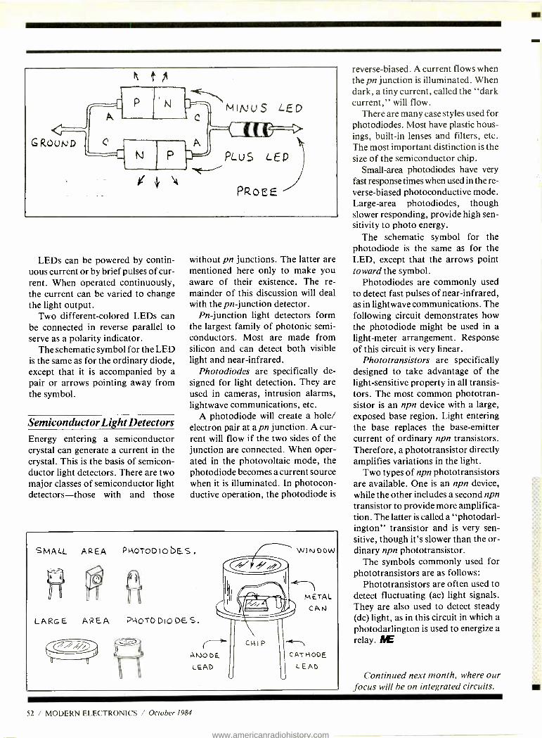
LEDs can be powered by contin- uous current or by brief pulses of cur- rent. When operated continuously, the current can be varied to change the light output.
Two different- colored LEDs can be connected in reverse parallel to serve as a polarity indicator.
The schematic symbol for the LED is the same as for the ordinary diode, except that it is accompanied by a pair or arrows pointing away from the symbol.
Semiconductor Light Detectors Energy entering a semiconductor crystal can generate a current in the crystal. This is the basis of semicon- ductor light detectors. There are two major classes of semiconductor light detectors -those with and those
without pn junctions. The latter are mentioned here only to make you aware of their existence. The re- mainder of this discussion will deal with the pn- junction detector.
Pn- junction light detectors form the largest family of photonic semi- conductors. Most are made from silicon and can detect both visible light and near -infrared.
Photodiodes are specifically de- signed for light detection. They are used in cameras, intrusion alarms, lightwave communications, etc.
A photodiode will create a hole/ electron pair at a pn junction. A cur- rent will flow if the two sides of the junction are connected. When oper- ated in the photovoltaic mode, the photodiode becomes a current source when it is illuminated. In photocon- ductive operation, the photodiode is
SMALL AREA PIAOTODIObES.
LARGE AREA
II NOTO DIO DES.
( i CHIP
ANODE LEAD
WINDOW
METAL
CAN
tTh
CATHODE
LEAD
reverse- biased. A current flows when the pn junction is illuminated. When dark, a tiny current, called the "dark current," will flow.
There are many case styles used for photodiodes. Most have plastic hous- ings, built -in lenses and filters, etc. The most important distinction is the size of the semiconductor chip.
Small-area photodiodes have very fast response times when used in the re- verse- biased photoconductive mode. Large -area photodiodes, though slower responding, provide high sen- sitivity to photo energy.
The schematic symbol for the photodiode is the same as for the LED, except that the arrows point toward the symbol.
Photodiodes are commonly used to detect fast pulses of near -infrared, as in lightwave communications. The following circuit demonstrates how the photodiode might be used in a light -meter arrangement. Response of this circuit is very linear.
Phototransistors are specifically designed to take advantage of the light- sensitive property in all transis- tors. The most common phototran- sistor is an npn device with a large, exposed base region. Light entering the base replaces the base -emitter current of ordinary npn transistors. Therefore, a phototransistor directly amplifies variations in the light.
Two types of npn phototransistors are available. One is an npn device, while the other includes a second npn transistor to provide more amplifica- tion. The latter is called a "photodarl- ington" transistor and is very sen- sitive, though it's slower than the or- dinary npn phototransistor.
The symbols commonly used for phototransistors are as follows:
Phototransistors are often used to detect fluctuating (ac) light signals. They are also used to detect steady (dc) light, as in this circuit in which a photodarlington is used to energize a relay. AIE
Continued next month, where our focus will be on integrated circuits.
52 / MODERN ELECTRONICS / October 1984
www.americanradiohistory.com

NEW!
Scanners Communications Electronics;"
the world's largest distributor of radio scanners, introduces new models with special savings on all radio scanners. Chances are the police, fire and weather emergencies you'll read about in tomorrows paper are coming through on a scanner today.
We give you excellent service be- cause CE distributes more scanners worldwide than anyone else. Our ware- house facilities are equipped to pro- cess thousands of scanner orders every week. We also export scanners to over 300 countries and military installations. Almost all items are in stock for quick shipment, so if you're a person who prefers fact to fantasy and who needs to know what's really happening around you, order your radio today from CE.
NEW! Regency/ MX5000 -E List price $599.95/CE price $359.00 Multi -Band, 20 Channel No- crystal scanner Search Lockout Priority AC /DC Selectable AM -FM modes LCD display World's first continuous coverage scanner Frequency range: 25 -550 MHz continuous coverage Never before have so many features come in such a small package. The Regency MX5000 mobile or home scanner has continuous cover- age from 25 to 550 MHz. That means you can hear CB, Television audio, FM broadcast sta- tions, all aircraft bands including military and the normal scanner bands, all on your choice of 20 programmable channels.
Regency® MX3000 -E List price $319.95/CE price $179.00 6-Band, 30 Channel No- crystal scanner Search Lockout Priority AC /DC Bands: 30-50, 144-174, 440 -512 MHz. The Regency Touch MX3000 provides the ease of computer controlled, touch -entry program- ming in a compact -sized scanner for use at home or on the road. Enter your favorite public service frequencies by simply touching the numbered pressure pads. You'll even hear a "beep" tone that lets you know you've made contact.
In addition to scanning the programmed channels, the MX3000 has the ability to search through as much as an entire band for an active frequency. The MX3000 includes channel 1
priority, dual scan speeds, scan or search delay and a brightness switch for day or night operation.
Regency® Z30 -E List price $279.95/CE price $169.00 6-Band, 30 Channel No-crystal scanner Bands: 30 -50, 144 -174, 440 -512 MHz. Cover your choice of over 15,000 frequencies on 30 channels at the touch of your finger.
Regency MX5000
Regency° C403 -E List price $99.95/CE price $59.00 5 -Band, 4 Channel Crystal scanner Channel indicator LED AC only Low cost Bands: 30 -50, 148.174, 450 -470 MHz Regency's basic scanner, the C403 gives you the excitement of police, fire and emergency calls at a budget price. It can tune in to any of five public service bands and brings the signal in loud and clear...on any of four possible channels. It comes with detachable telescope antenna and AC power cord. Order one crystal certificate for each channel you want to receive.
Regency° HX1000 -E List price $329.95/CE price $209.00 6 -Band, 30 Channel No Crystal scanner Search Lockout Priority Scan delay Sidelit liquid crystal display Digital Clock Frequency range: 30 -50, 144-174, 440 -512 MHz. The new handheld Regency HX1000 scanner is fully keyboard programmable forthe ultimate in versatil- ity. You can scan up to 30 channels at the same time. When you activate the priority control, you automat- ically override all other calls to listen to your favorite frequency. The LCD display is even sidelit for night use. A die -cast aluminum chasis makes this the most rugged and durable hand -held scanner avail- able. There is even a backup lithium battery to main- tain memory for two years. Includes wall charger, carrying case, belt clip, flexible antenna and nicad battery. Order your Regency HX1000 now.
Regency® R106 -E Lost price $159.95/CE price $92.00 5 -Band, 10 Channel Crystal scanner AC /DC Frequency range: 30 -50, 146 -174, 450 -512 MHz. Aversatile scanner, The Regency R -106 is built to provide maximum reception at home or on the road. Rugged cabinet protects the advanced design circuitry allowing you years of depend- able listening.
NEW! Regency® R1050 -E Lost price $179.95/CE price $109.00 6 -Band, 10 Channel Crystalless AC only Frequency range: 30 -50, 144 -174, 440 -512 MHz. Now you can enjoy computerized scanner ver- satility at a price that's less than some crystal units. The Regency R1050 lets you in on all the action of police, fire, weather, and emergency calls. You'll even hear mobile telephones.
Programming the R1050 is easy. Merely touch the keyboard and enter any of over 15,000 frequencies on your choice of 10 channels.
Regency® HX650 -E Lost price $129.95/CE price $79.00 5 -Band, 6 Channel Handheld crystal scanner Bands: 30 -50, 146 -174, 450 -512 MHz. Now you can tune in any emergency around town, from wherever you are, the second it happens. Advanced circuitry gives you the world's smallest scanner. Our low CE price in- cludes battery charger /A.C. adapter.
NEW! Regency° HX- 650P -E List Price $189.95/CE price $104.00 Now, Communications Electronics offers a special packaged price on the Regency HX -650 scanner and the following items foronly$104.00. You get the Regency H X -650 scanner, a set of 4 AAA ni -cad batteries, the MA -506 carrying case, six crystal certificates, AC adapter /charger and flexible rubber antenna for only $104.00 per package plus $10.00 shipping /handling. To order this special package, use CE special order number HX- 650P -E.
QUANTITY DISCOUNTS AVAILABLE Order two scanners at the same time and deduct 1 %, for three scanners deduct 2 %, four scanners deduct 3 %, five scanners deduct 4% and six or more scanners purchased at the same time earns you a 5% discount off our super low single unit price.
Regency HX1000
Regency HX65O
uuu
NEW! Regency° MX7000 -E List price $699.95/CE price $449.00 10 -Band, 20 Channel Crystalless AC /DC Frequencyrange: 25 -550 MHz continuous coverage and 800 MHz. to 1.2 GHz. continuous coverage In addition to normal scanner listening, the MX7000 offers CB, VHF, and UHF TV audio, FM Broadcast, all aircraft bands (civil and military), 800 MHz communications, cellular telephone, and when connected to a printer or CRT, satellite weather pictures.
The Regency Touch MX7000 provides the ease of computer controlled, touch -entry pro- gramming in a compact -sized scanner for use at home or on the road. Enter your favorite fre- quencies by simply touching the numbered pressure pads. You'll even hear a "beep" tone that lets you know you've made contact.
In addition to scanning the programmed chan- nels, the MX7000 has the ability to search through as much as an entire band for an active frequency. When a call is received, the frequency will appear on the digital display.
Regency° Z10 -E List price $239.95/CE price $138.00 6-Band, 10 Channel No-crystal scanner Priority control Search/Scan AC /DC Bands: 30 -50, 140-174, 440 -512 MHz. Cover your choice of over 15,000 frequencies on 10 channels at the touch of your finger.
OTHER RADIO ACCESSORIES B-4 -E 1.2 V MA Ni -Cad batteries (set of four) $9.00 A- 135C -E Crystal certificate $3.00 A60-E Magnet mount mobile antenna $35.00 A70-E Base station antenna $35.00 Add $3.00 shipping for all accessories ordered at the same time. Add $3.00 shipping per scanner antenna.
BUY WITH CONFIDENCE To get the fastest delivery from CE of any scanner, send or phone your order directly to our Scanner Distribution Center" Be sure to calculate your price using the CE prices in this ad. Michigan residents please add 4% sales tax or supply your tax I.D. number. Written pur- chase orders are accepted from approved gov- ernment agencies and most well rated firms at a 10% surcharge for net 10 billing. All sales are subject to availability, acceptance and verifica- tion. All sales on accessories are final. Prices, terms and specifications are subject to change without notice. All prices are in U.S. dollars. Out of stock items will be placed on backorder automatically unless CE is instructed differ- ently. A $5.00 additional handling fee will be charged for all orders with a merchandise total under $50.00. Shipments are F.O.B. Ann Arbor, Michigan. No COD's. Most products that we sell have a manufacturer's warranty. Free copies of warranties on these products are available prior to purchase by writing to CE. International orders are invited with a $20.00 surcharge for special handling in addition to shipping charges. Non -certified checks require bank clearance.
Mail orders to: Communications Electron- ics,- Box 1002, Ann Arbor, Michigan 48106 U.S.A. Add $7.00 per scanner for U.P.S. ground shipping and handling in the continental U.S.A. For Canada, Puerto Rico, Hawaii, Alaska, or APO /FPO delivery, shipping charges are three times continental U.S. rates. If you have a Visa or Master Card, you may call and place a credit card order. Order toll -free in the U.S. Dial 800 -521 -4414. In Canada, order toll -free by calling 800 -221 -3475. WUI Telex CE anytime, dial 671 -0155. If you are outside the U.S. or in Michigan dial 313- 973 -8888. Order today. Scanner Distribution Center" and CE logos are trade- marks of Communications Electronics Inc. # Regency is a federally registered trademark of Regency Electronics Inc. AD *080384 -E
Copyright e 1984 Communications Electronics
Order Toll Free... call 1- 800 -521 -4414
iM
//COMMUNICATIONS ELECTRONICS"
Consumer Products Division 818 Phoenix O Box 1002 O Ann Arbor, Michigan 48106 U.S.A. Call TOLL -FREE 800.5214414 or outside U.S.A. 313. 9734888
CIRCLE 37 ON READER SERVICE CARD
www.americanradiohistory.com
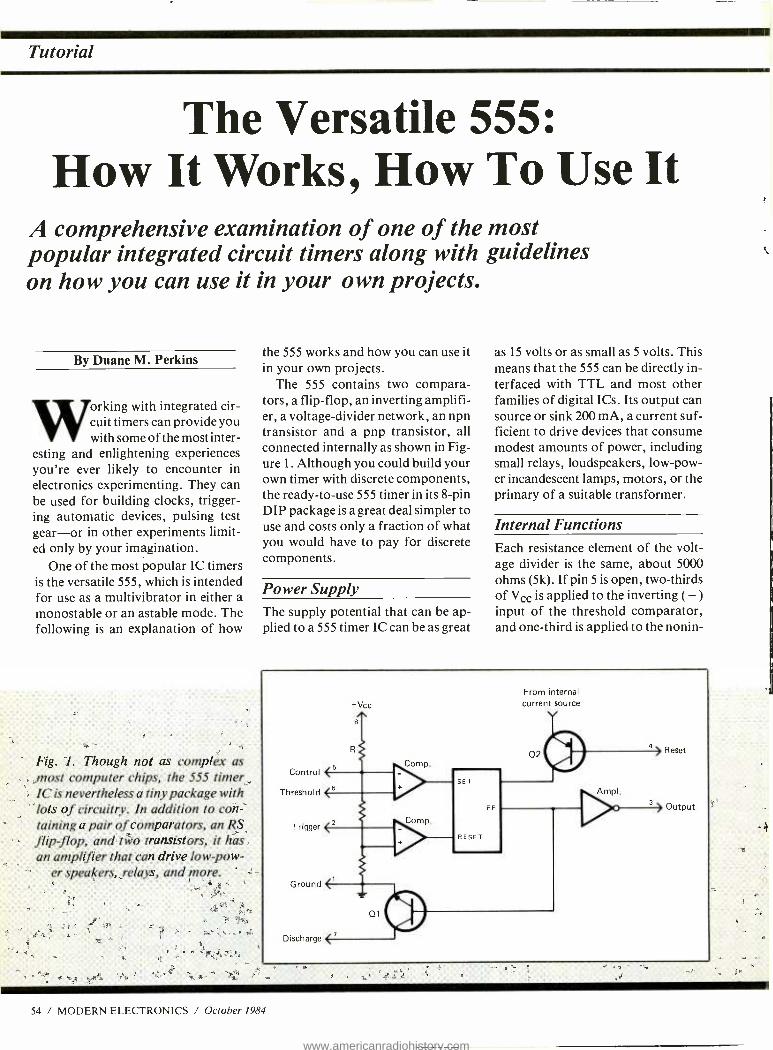
Tutorial
The Versatile 555: How It Works, How To Use It
A comprehensive examination of one of the most popular integrated circuit timers along with guidelines on how you can use it in your own projects.
By Duane M. Perkins
orking with integrated cir- cuit timers can provide you with some of the most inter-
esting and enlightening experiences you're ever likely to encounter in electronics experimenting. They can be used for building clocks, trigger- ing automatic devices, pulsing test gear -or in other experiments limit- ed only by your imagination.
One of the most popular IC timers is the versatile 555, which is intended for use as a multivibrator in either a monostable or an astable mode. The following is an explanation of how
Fig. 1. Though not as complex as most computer chips, the 555 timer IC is nevertheless a tiny package with lots of circuitry. In addition to con- taining a pair of comparators, an RS flip-flop, and two transistors, it has an amplifier that can drive low -pow-
er speakers, relays, and more.
the 555 works and how you can use it in your own projects.
The 555 contains two compara- tors, a flip -flop, an inverting amplifi- er, a voltage- divider network, an npn transistor and a pnp transistor, all connected internally as shown in Fig- ure 1. Although you could build your own timer with discrete components, the ready -to -use 555 timer in its 8 -pin DIP package is a great deal simpler to use and costs only a fraction of what you would have to pay for discrete components.
Power Supply The supply potential that can be ap- plied to a 555 timer IC can be as great
as 15 volts or as small as 5 volts. This means that the 555 can be directly in- terfaced with TTL and most other families of digital ICs. Its output can source or sink 200 mA, a current suf- ficient to drive devices that consume modest amounts of power, including small relays, loudspeakers, low -pow- er incandescent lamps, motors, or the primary of a suitable transformer.
Internal Functions Each resistance element of the volt- age divider is the same, about 5000 ohms (5k). If pin 5 is open, two -thirds of Vcc is applied to the inverting (- ) input of the threshold comparator, and one -third is applied to the nonin-
Control ( 5
Threshold <6
Trigger < 2
Ground
+Vcc
8
Discharge <
Q1
SE,
RESET
From internal current source
Q2 4) Reset
Output
54 / MODERN ELECTRONICS / October 1984
www.americanradiohistory.com
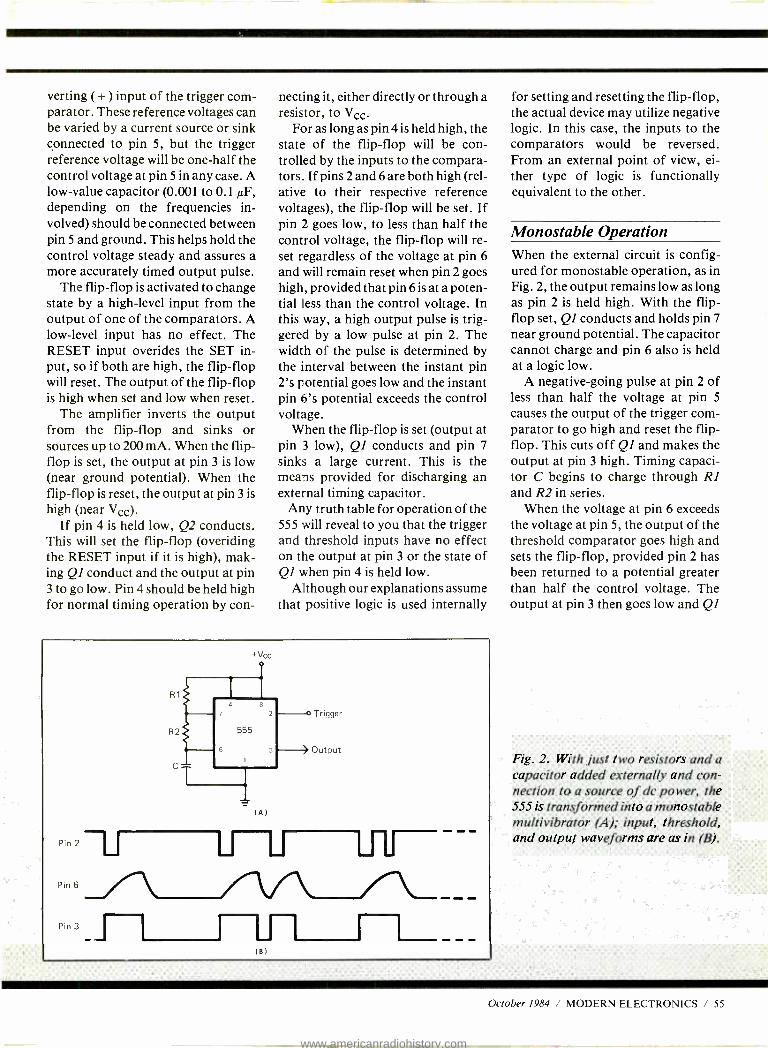
verting ( + ) input of the trigger com- parator. These reference voltages can be varied by a current source or sink connected to pin 5, but the trigger reference voltage will be one -half the control voltage at pin 5 in any case. A low -value capacitor (0.001 to 0.1 µF, depending on the frequencies in- volved) should be connected between pin 5 and ground. This helps hold the control voltage steady and assures a more accurately timed output pulse.
The flip -flop is activated to change state by a high -level input from the output of one of the comparators. A low -level input has no effect. The RESET input overides the SET in- put, so if both are high, the flip -flop will reset. The output of the flip -flop is high when set and low when reset.
The amplifier inverts the output from the flip -flop and sinks or sources up to 200 mA. When the flip - flop is set, the output at pin 3 is low (near ground potential). When the flip -flop is reset, the output at pin 3 is
high (near Vcc). If pin 4 is held low, Q2 conducts.
This will set the flip -flop (overiding the RESET input if it is high), mak- ing Ql conduct and the output at pin 3 to go low. Pin 4 should be held high for normal timing operation by con-
necting it, either directly or through a resistor, to Vcc.
For as long as pin 4 is held high, the state of the flip -flop will be con- trolled by the inputs to the compara- tors. If pins 2 and 6 are both high (rel- ative to their respective reference voltages), the flip -flop will be set. If pin 2 goes low, to less than half the control voltage, the flip -flop will re- set regardless of the voltage at pin 6
and will remain reset when pin 2 goes high, provided that pin 6 is at a poten- tial less than the control voltage. In this way, a high output pulse is trig- gered by a low pulse at pin 2. The width of the pulse is determined by the interval between the instant pin 2's potential goes low and the instant pin 6's potential exceeds the control voltage.
When the flip -flop is set (output at pin 3 low), Ql conducts and pin 7
sinks a large current. This is the means provided for discharging an external timing capacitor.
Any truth table for operation of the 555 will reveal to you that the trigger and threshold inputs have no effect on the output at pin 3 or the state of QI when pin 4 is held low.
Although our explanations assume that positive logic is used internally
P. r' í:
PI
li
+Vcc
Trigger
Output
-L_ _ _ _
for setting and resetting the flip -flop, the actual device may utilize negative logic. In this case, the inputs to the comparators would be reversed. From an external point of view, ei- ther type of logic is functionally equivalent to the other.
Monostable Operation When the external circuit is config- ured for monostable operation, as in Fig. 2, the output remains low as long as pin 2 is held high. With the flip - flop set, QI conducts and holds pin 7
near ground potential. The capacitor cannot charge and pin 6 also is held at a logic low.
A negative -going pulse at pin 2 of less than half the voltage at pin 5
causes the output of the trigger com- parator to go high and reset the flip - flop. This cuts off QI and makes the output at pin 3 high. Timing capaci- tor C begins to charge through RI and R2 in series.
When the voltage at pin 6 exceeds the voltage at pin 5, the output of the threshold comparator goes high and sets the flip -flop, provided pin 2 has been returned to a potential greater than half the control voltage. The output at pin 3 then goes low and QI
Fig. 2. With just two resistor's and a capacitor added externally and con- nection to a source of dc power, the 555 is transformed into a monostable multivibrator (A); input, threshold, and output waveforms are as in (B).
October 1984 / MODERN ELECTRONICS / 55
www.americanradiohistory.com

A. tc = C(R1 + R2)[In(1
B. Vd=Vice - td
CR2
Vd)-ln(1- Vc
'cc Vcc
C. tc = C(R1+R2) [ - ln(i
D.
E.
tc = C(Vc - Vd)
2Vcc
3 Vcc
= CR2( -1n.5) = 0.693 CR2
F. fo
) = 1.1 C(R1+R2)
C(R1 + R2) [1n(1 - Vc ) - ln(1 VC ) + .693CR2 2Vcc Vcc
G. tc = C(R1 + R2) [In(1 - -)- In(1 - 2 )[ = 0.693 C(R1 + R2 )
3 3
H. fo - 1 1.44
.693C(R1 +2R2) C(R1 +2R2)
1.44 I. fo = = 0.0218 Hz
lO x 10-6 x (103 + 2 x 3.3 x 106)
Fig. 3. By adding a constant -current source -the transistor shown in (A) -you can design and build a timer circuit that generates a sawtooth waveform, as in (B), that can be used to drive the horizontal amplifier of an oscilloscope, other applications.
begins to conduct. The capacitor will discharge through R2.
When the voltage at pin 6 drops to less than voltage at pin 5, the output of the threshold comparator goes low. However, the flip -flop will re- main set, since its state can be changed only by a high input. The ca- pacitor will continue to discharge un- til another trigger pulse arrives.
The width of the output pulse is a function of the time required for the capacitor to charge to the voltage at pin 5. Variations in Vcc have little ef- fect because both the reference and charge voltages are equally affected, provided that Vcc is the source for both. Charge time is calculated from formula A (see "Formula" box), where tc is the charging interval; Vd is the voltage on the capacitor at the beginning of interval tc; Vc is the con- trol voltage at pin 5; and ln is the sym- bol in mathematics for the natural logarithm function.
The voltage on the capacitor at the instant the trigger pulse arrives can be calculated as in formula B. Here is the base of the natural logarithms,
Pin 2
Pin 6
Pin 3
+Vcc
(AÍ
Trigger
Output
(B)
56 / MODERN ELECTRONICS / October 1984
www.americanradiohistory.com

and tc is the interval between the ar- rival of the trigger pulse and the end of the preceding output pulse. If td is at least 5CR2, Vd can be assumed to be zero, in which case the term In [1 - (Vd /Vcc)] is zero. Assuming pin 5 is open and the control voltage is two -thirds Vcc, formula C gives the result calculated.
For example, if C = 0.1µF and RI + R2 = l k ohms, then tc = 1.1 x .1 x 10 - 6 x 10' = 110 microsec- onds.
In most applications, the discharge time should be made as short as pos- sible to allow the trigger pulses to be as close together as possible without affecting the width of the output pulse. This is accomplished by elimi- nating R2 and connecting the capaci- tor and pin 6 directly to pin 7. The discharge will then be as rapid as pos- sible, and the interval will depend only on the value of the capacitor.
By selecting the lowest value of ca- pacitance that will give the required pulse width in combination with R1, the discharge time will be minimized. Because the comparators have a very
high input resistance, the value of RI can be as great as 3.3 megohms.
Any trigger pulse that occurs dur- ing an output pulse is simply ignored, because the flip -flop is already reset. However, if pin 2 is held low beyond the end of the normal charging inter- val, the capacitor will continue to charge and the output will remain in the high state for the duration of the trigger pulse.
If the trigger pulse is generated by a mechanical momentary- contact switch, the multiple pulses resulting from contact bounce will have no ef- fect, provided the pulse width ex- ceeds the period of contact bounce. A clean pulse of constant width will be generated each time the switch is mo- mentarily closed.
If the charging rate is held con- stant, the voltage- versus -time curve will be linear and the charging inter- val will be linear with respect to the control voltage. This can be accom- plished by supplying the charging current from a constant -current source such as the transistor circuit shown in Fig. 3.
Charging rate can be controlled by varying base -bias current in the tran- sistor. When the circuit is triggered, the charge build -up results in a saw - tooth waveform voltage at pin 6. Such a waveform can be used to drive the horizontal amplifier of an oscil- loscope.
Since the sweep occurs only when the circuit is triggered, this current can be used as the basis for a trig- gered -sweep oscilloscope. The sweep time can be set by controlling the rate of charge.
With a constant rate of charge, the charging interval is given by formula D, where I is the charging current. For example, if Vc = 10 volts, Vd is
zero, C =0.1µF and I = 10mA, then
tc= 0.1x10 -6x10 10 x i0 -3
= 100 microseconds.
td is calculated as in formula E. Pulse width can be changed by
varying the voltage at pin 5. How- ever, the variation will not be linear unless the charging rate is constant.
Fig. 4. A slight modification of the Fig. 3 circuit, as shown in (A), pro- duces a timer circuit that can continu- ally be retriggered whenever a pulse is applied to the trigger in -out at the
base of the transistor.
October 1984 / MODERN ELECTRONICS / 57
www.americanradiohistory.com

With the constant -current charging source shown in Fig. 3, charging rate can be varied by coupling a signal to the base of the transistor . Pulse width will vary linearly with signal voltage variation. The charging interval must be shorter than the triggering inter- val, and the trigger pulse should be short to prevent holding the output high beyond the length of the charg- ing interval.
Voice- frequency signals can also be transmitted on the pulses with good results, but only if the carrier frequency (input at pin 2) is many times the highest audio frequency component of the signal.
If the output of a monostable cir- cuit is used to actuate a voltmeter (or a milliameter in series with a suitable resistance), the meter reading will be proportional to the trigger frequen- cy. Since pulse width is fixed, the ra- tio of pulse width to triggering period will increase with frequency. The me- ter will respond to the average volt- age level because of the inertia of the pointer's movement.
At low frequencies, a capacitor can be used to integrate the pulses and prevent vibration of the meter's pointer. To prevent the meter read- ing from being affected by supply voltage variations, regulate either the supply voltage or the output current. A circuit like this can be the basis for a frequency meter or tachometer.
If there is a provision in the exter- nal circuit that allows the timing ca- pacitor to discharge whenever a trig- ger pulse arrives, the circuit can be continually retriggered during the charging interval. Such a circuit is
shown in Fig. 4. The output remains high as long as the interval between trigger pulses is shorter than the charging interval set by the timing ca- pacitor and resistors. The circuit functions as a missing -pulse detec- tor, since the output goes low if a trig- ger pulse does not arrive before the charging interval has elapsed.
One possible use for the Fig. 4 cir- cuit would be to start and stop a cas- sette recorder under voice control. An amplified signal from the micro-
phone provides the trigger pulses, and the output could be used to oper- ate a relay that opens or closes a cir- cuit to the remote control jack of the cassette recorder.
Astable Operation In its astable mode, the 555's circuit is free -running. To obtain free -run- ning operation simply connect pin 2
to pin 6. When the charge on the ca- pacitor drops to less than half the voltage at pin 5, the trigger compara- tor output goes high, resetting the flip -flop. The timing capacitor then begins to charge. When the charge voltage exceeds the potential at pin 5, the threshold comparator goes high and sets the flip -flop. The cycle re- peats continuously.
The frequency of oscillation can be determined by calculating the sum of the charge and discharge times, and taking the reciprocal of the result. The charge on the capacitor will vary between the two limits set by the ref- erence voltages on the comparators. The charging interval can be calculat- ed using the formula given above for the monostable circuit, recognizing that Vd will be one -half of Vc.
The discharge interval is calculated from formula F, and the frequency of oscillation with formula G.
If pin 5 is open, the charging inter- val is determined using formula H, and the frequency will be calculated as in formula I.
The maximum possible frequency is limited by two considerations. At- tempts to reduce the value of the tim- ing capacitor below about 0.001 µF will be significantly affected by inter- nal capacitance. The device can sometimes be made to oscillate on in- ternal capacitance alone, but if the frequency is to be determined by the value of the timing capacitor, it should not be less than 0.001 F.
Attempts to reduce the resistance of 121+ R2 will increase the current through QI during the discharge in- terval. This current is the sum of Vcc
divided by RI plus the instantaneous discharge current. While the value of
R2 can be safely reduced to zero, the value of RI must be high enough to avoid swamping Ql or even destroy- ing it with excessive current. A cur- rent of 15 mA is within the safe range. Frequencies well beyond 100 kHz are attainable.
The minimum possible frequency is limited only by the value of the tim- ing capacitor, but care must be taken to assure that the current through QI is not excessive. With a high -value ca- pacitor and a low value for R2, the high discharge current could destroy Ql. However, the resistance of RI +R2 should not exceed about 3.3 megohms and should be low corn - pared to the actual leakage of the tim- ing capacitor used.
If RI = lk,R2 = 3.3M,C =10µF and there is no leakage, then formula J applies and the period will be one cycle every 45.9 seconds.
The astable circuit can be triggered at any time during the discharge in- terval. This can be accomplished by connecting a resistor between pins 2
and 6 and coupling the trigger pulse to pin 2 through another resistor. The resistances must be chosen so that the potential at pin 2 will go below the trigger reference level while pin 6 is
high. In this way, the circuit can be made to lock -in on a frequency that is
somewhat greater than the free -run- ning frequency.
If the trigger frequency is slightly greater than a multiple of the free - running frequency, the trigger pulses that occur during the charging inter- val will be ignored and the circuit will lock -in on a submultiple of the trig- ger frequency. The circuit then acts as a frequency divider. The monosta- ble circuit will act in the same manner but will not be free running in the ab- sense of trigger pulses.
The astable circuit is not capable of generating a symmetrical square wave. The charging interval must ex- ceed the discharge interval because the capacitor charges through RI and
Continued on page 100
58 / MODERN ELECTRONICS / October 1984
www.americanradiohistory.com
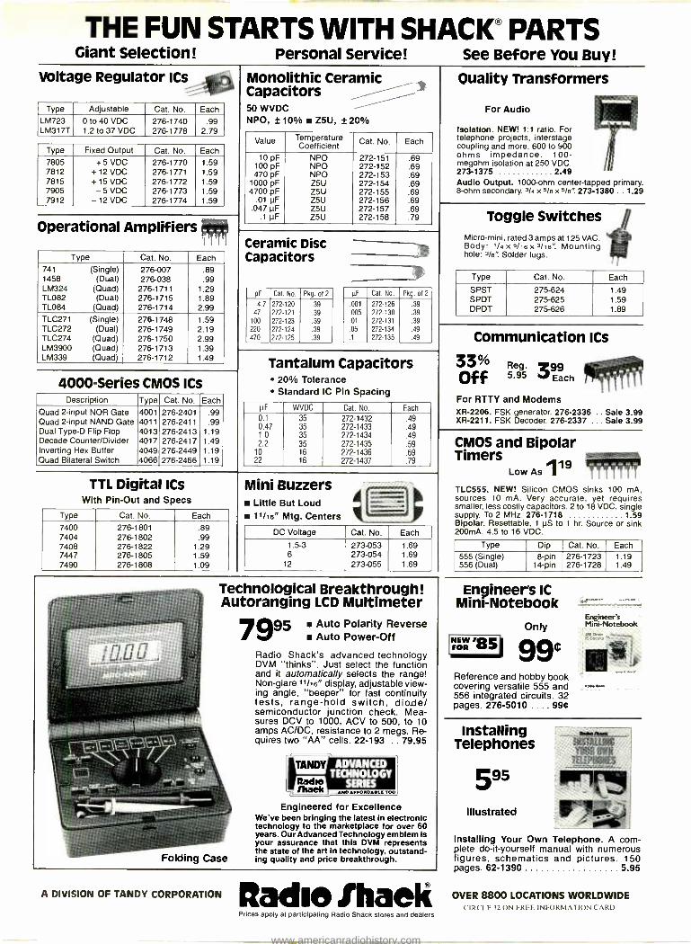
THE FUN STARTS WITH SHACK® PARTS Giant Selection! Personal Service! See Before You Buy!
Voltage Regulator ICs
Type Adjustable Cat. No. Each LM723 LM317T
0 to 40 VDC 1.2 to 37 VDC
276 -1740 276 -1778
.99 , 2.79
Type Fixed Output Cat. No. Each 7805 +5 VDC 276 -1770 1.59 7812 + 12 VDC 276 -1771 1.59 7815 + 15 VDC 276 -1772 1.59 7905 -5 VDC 276 -1773 1.59 7912 -12 VDC 276 -1774 1.59
Operational Amplifiers
Type Cat. No. Each
741 (Single) 276 -007 .89 1458 (Dual) 276 -038 .99 LM324 (Quad) 276 -1711 1.29 TL082 (Dual) 276 -1715 1.89 TL084 (Quad) 276 -1714 2.99 TLC271 (Single) 276 -1748 1.59 TLC272 (Dual) 276 -1749 2.19 TLC274 (Quad) 276 -1750 2.99 LM3900 (Quad) 276 -1713 1.39 LM339 (Quad) 276 -1712 1.49
Monolithic Ceramic Capacitors 50 WVDC WVDC NPO, ±10% Z5U, ±20%
Value Temperature Coefficient Cat. No. Each
10 pF NPO 272 -151 .69 100 pF NPO 272 -152 .69 470 pF NPO 272 -153 .69
1000 pF Z5U 272 -154 .69 4700 pF Z5U 272 -155 .69
.01 pF Z5U 272 -156 .69 .047 pF Z5U 272 -157 .69
.1 pF Z5U 272 -158 .79
Quality Transformers
For Audio
Isolation. NEW! 1:1 ratio. For telephone projects, interstage coupling and more. 600 to 900 ohms impedance. 100 - megohm isolation at 250 VDC. 273 -1375 2 49 Audio Output. 1000 -ohm center -tapped primary. 8 -ohm secondary. 3/4 x 5/e x 5 /e" 273 -1380 . . 1.29
Ceramic Disc Capacitors
pF Cat. No. Pkg. of 2
4.7 272 -120 .39 47 272 -121 .39
100 272 -123 .39 220 272 -124 .39 470 272 -125 .39
µF Cat. No. Pkg. of 2
.001 272 -126 .39
.005 272 -130 .39
.01 272 -131 .39
.05 272 -134 .49
.1 272 -135 .49
Toggle Switches Micro -mini, rated 3 amps at 125 VAC. Body 1/4x5 /16X3//6' Mounting hole: Na': Solder lugs.
Type Cat. No. Each
SPST 275 -624 1.49 SPDT 275 -625 1.59 DPDT 275 -626 1.89
4000 -Series CMOS ICs Description Type Cat. No. Each
Quad 2 -input NOR Gate 4001 276 -2401 .99 Quad 2 -input NAND Gate 4011 276 -2411 .99 Dual Type -D Flip Flop 4013 276 -2413 1.19 Decade Counter /Divider 4017 276 -2417 1.49 Inverting Hex Buffer 4049 276 -2449 1.19 Quad Bilateral Switch 4066 276 -2466 1.19
Tantalum Capacitors 20% Tolerance Standard IC Pin Spacing
pF WVDC Cat. No. Each
0.1 35 272 -1432 .49 0.47 35 272 -1433 .49 1.0 35 272 -1434 .49 2.2 35 272 -1435 .59
10 16 272 -1436 .69 22 16 272 -1437 .79
Communication ICs
33% 5.95 3 Each Off
For RTTY and Modems XR -2206. FSK generator. 276 -2336 .. Sale 3.99 XR -2211. FSK Decoder. 276 -2337 ... Sale 3.99
TTL Digital ICs With Pin -Out and Specs
Type Cat. No. Each
7400 276 -1801 .89 7404 276 -1802 .99 7408 276 -1822 1.29 7447 276 -1805 1.59 7490 276 -1808 1.09
Mini Buzzers Little But Loud 11/16" Mtg. Centers
MOVE _
DC Voltage Cat. No. Each
1.5 -3 273 -053 1.69 6 273 -054 1.69
12 273 -055 1.69
Technological Breakthrough! Autoranging LCD Multimeter
7995 Auto Polarity Reverse Auto Power -Off
Radio Shack's advanced technology DVM "thinks ". Just select the function and it automatically selects the range! Non -glare 11/16" display, adjustable view- ing angle, "beeper" for fast continuity tests, range -hold switch, dio.de/ semiconductor junction check. Mea- sures DCV to 1000, ACV to 500, to 10 amps AC /DC, resistance to 2 megs. Re- quires two "AA" cells. 22 -193 . 79.95
Folding Case
ADVANCED TECHNOLOGY
EaSERIES ... MOT TiOIIGLE TOO
Engineered for Excellence We've been bringing the latest in electronic technology to the marketplace for over 60 years. Our Advanced Technology emblem is your assurance that this DVM represents the state of the art in technology, outstand- ing quality and price breakthrough.
A DIVISION OF TANDY CORPORATION it adle Ihaelt Prices apply at participating Radio Shack stores and dealers
CMOS and Bipolar Timers 119
Low As !FM TLC555. NEW! Silicon CMOS sinks 100 mA, sources 10 mA. Very accurate, yet requires smaller, less costly capacitors. 2 to 18 VDC, single supply. To 2 MHz. 276 -1718 1 59 Bipolar. Resettable, 1 NS to 1 hr. Source or sink 200mA. 4.5 to 16 VDC.
Type Dip Cat. No. Each
555 (Single) 556 (Dual)
8 -pin 14 -pin
276 -1723 276 -1728
1.19 1.49
Engineer's IC Mini- Notebook
NEW /0 FOR vi
Only
99e Reference and hobby book covering versatile 555 and 556 integrated circuits. 32 pages. 276 -5010 .... 99¢
Engineer's Mini - Notebook
Installing Telephones
595
Illustrated
NTAIItSIC 1rdAl INN_
Installing Your Own Telephone. A com- plete do- it- yourself manual with numerous figures, schematics and pictures. 150 pages. 62 -1390 5 95
OVER 8800 LOCATIONS WORLDWIDE CIRCLE 32 ON FREE INFORMATION CARD
www.americanradiohistory.com

Diskette Users... When you've heard from all the animals in the diskette zoo, but you need fast delivery and high quality diskettes...
Call Communications Electronics Diskette order desk
800 -USA -DISK In Canada 800 -CA1 -DISK
Choose your brand
Choose your price Product Description
8" SSSD IBM Compatible 128B/S, 26 Sector 8" SSSD Shugart Compatible, 32 Hard Sector 8" SSDD IBM Compatible(128 B /S, 26 Sectors)
8" DSDD Soft Sector (Unformated) 8" DSDD Soft Sector (256 B /S, 26 Sectors) 8" DSDD Soft Sector (51 2 B /S, 15 Sectors) 8" DSDD Soft Sector (1024 B /S, 8 Sectors) 51/4" SSSD Soft Sector w /Hub Ring
51/4" SSSD Same as above but bulk product
51/4" SSSD 10 Hard Sector w /Hub Ring
51/4" SSDD Soft Sector w /Hub Ring
51/4" SSDD Same as above, but bulk product
51/4" SSDD Soft Sector Flippy (use both sides)
51/4" SSDD 10 Hard Sector w /Hub Ring
51/4" DSDD Soft Sector w /Hub Ring
51/4" DSDD Same as above, but bulk product
51/4" DSDD 10 Hard Sector w /Hub Ring
51/4" DSDD 16 Hard Sector w /Hub Ring
51/4" DSDD Soft Sector w /Hub Ring (96 TPI)
31/2" SSDD Soft Sector micro-floppy
Super Disk
A BASF .
Super Disk
diskettes l $0.94 each
CE put Sau Dlak 100 Pria
Pirt # pur lhk (SI
Wabash
diskettes tt.. $0.99 each
CE quail 19akuik 100 Pria Part # per disk (S)
BASF
diskettes t p
$1.44 each CE quiet
BASF 100 Pria Part # Per Ilsk (S)
FIII-P 1.59
F31 A-P 1.79
FI31-P 1.89
FI4A-P 2.09
Fl 44-P 2.09
FI45-P 2.09
F147-P 2.09 -- 6431 -P 1.14 M11A-P 1.19
6437 -P 0.94 MIIAB-P 0.99
M41 A-P 1.19
6461 -P 1.29 M13A-P 1.34 54974 -P 1 44
6467 -P 1.09 M13AB-P 1.14
M18A-P 1.99
M435-P 1.34
6491 -P 1.54 M14A-P 1.59 54990 -P 1.79
6497 -P 1.34 M1409-P 1.39
M44A-P 1.59
M54A-P 1.59
6501 -P 2.44 M160-P 2.49 54992 -P 2.99 -- 54112 -P 2.74
For more information Lifetime warranty
hr rn ldr n brpr 9bY cull
800 -USA -DISK about this brand call: luMlcklaaa313- 913 -1111
6 year warranty Lifetime warranty Fn Mn III as N uiI For Mn Idr a lADF call
800 -323 -9868 800- 343 -4600 la Illlula 312-593-6363 Ia Mauaaautta 611-271-4000
CIRCLE b2 ON READER SERVICE CARD
3M diskettes tß.ú
$1.44 each
3M Part #
BOSSO-P
888DD-P
8DSD0-P
8D800-1024-P
CE gout 100 Pries
Per Ilsk (S)
1.94
2.39
2.89
2.89
58800 -RH -P 1.64
5SSDD -BL -P 1.44
5DSD0 -RH -P
5DS00- 96RH -P
3SSMD -P
2.19
3.09
3.74
Lifetime warranty Fir Mn ldr n 3M cull
800 -328 -9438 Is Mluasda 612-736-9524
www.americanradiohistory.com
CE...your best source for diskettes For you the diskette buyer, it's a jungle out there. There are so many different brands to choose from, you need to go on a safari to find a good brand at a reasonable cost. Fortunately, CE has already hunted for the best diskettes and offers you an excellent choice at a CE price. To save you even more, CE also offers bulk product where 100 diskettes are packed in the same box without envelopes or labels. Since we save packaging costs, these savings are passed on to you. Diskette envelopes are also available from CE. These super strong and tear resistant Tyvek° envelopes are only $15.00 per 100 pack. Use order# TE -5 for a 100 pack of 51/4" diskette envelopes.
Quantity Discounts Available Our diskettes are packed 10 disks to a carton and 5 or 10 cartons to a case. The economy bulk pack is packaged 100 disks to a case without envelopes or labels. Please order only in increments of 100 units for quantity 100 pricing. With the exception of bulk pack, we are also willing to accommodate your smaller orders. Quantities less than 100 units are available in increments of 10 units at a 20% surcharge above our 100 unit price. Quantity discounts are also available. Order 300 or more disks at the same time and deduct 1%; 500 or more saves you 2%; 1,000 or more saves 3%; 2,000 or more saves 4%; 5,000 or more saves 5%; 10,000 or more saves 6%; 50,000 or more saves 7%, 100,000 or more saves 8%, 500,000 or more saves 9% and 1,000,000 or more disks earns you a 10% discount off our super low quantity 100 price. Almost all our diskettes are immediately available from CE. Our efficient warehouse facilities are equipped to help us get you the quality product you need, when you need it. If you need further assistance to find the flexible diskette that's right for you, call the appropriate manufacturers compatibility hotline telephone number listed at the bottom of this ad. Dealer inquiries invited.
Verbatim diskettes u $1.59 each
CE gant Verbatim 100 Pria Pert # per disk IS)
28820 -P 1 59
28821 -P 2.54
28823 -P 3.39
Memorex diskettes p $1.59 each
Memorex Pert #
HI11111 11NIt UI1,1
ULTRA
Ultra diskettes t p
$1.59 each CE punt CE gant 100 Pria Ultra 100 price
per disk 15) Part # per disk IS)
3062 -P 1.94
3015 -P 1.94
3090 -P 2.39
3102 -P 2.89
3104-P 2.89
3481 -P 1.59
3491 -P 2.19
3501 -P 2.99
6100 -P 3.74
Lifetime warranty 5 year warranty For mare into on Verbatim call Fer man Ide II Mamoru call
800 -538 -8589 In California 408- 245 -4400
800-448-1422 Mn1ay-Friday Baro-4Pa ET
81726-P 1.94
82701-P 2.89
82708-P 2.89
51401 -P 1.59
52402 -P 1.99
52401 -F 2.19
52801 -P 2.99
Lifetime warranty Fer mart Ide n Ultra call
408-728-7777 Mn1tY-Friday 9 ae-4 Pa PT
CIRCLE 63 C);
Buy your diskettes from CE with confidence To get the fastest delivery of your diskettes, phone your order directly to our order desk and charge it to your credit card. Written purchase orders are accepted from approved government agencies and most well rated firms at a 10% surcharge for net 10 billing. For maximum savings, your order should be prepaid. All sales are subject to availability, accept- ance and verification. All sales are final. All prices are in U.S. dollars. Prices, terms and specifications are subject to change without notice. Out of stock items will be be placed on backorder or substituted for equivalent product at no extra cost to you unless CE is instructed differently. A$5.00 additional handling fee will be charged for all orders with a merchandise total under $50.00. All shipments are F.O.B. CE warehouse in Ann Arbor, Michigan. COD terms are available, in U.S. UPS areas for$5.00 extra, and are payable with cash or certified check
For shipping charges add $8.00 per 100 diskettes and /or any fraction of 100 8 -inch diskettes, or $6.00 per 100 diskettes and /or any fraction of 100 51/4 -inch or31 /2-inch diskettes for U.P.S. ground shipping and handling in the continental U.S. UPS 2nd day air rates are three times continental U.S. rates. For Canada, Puerto Rico, Hawaii, Alaska, or APO /FPO delivery, shipping is three times the continental U.S. rate.
Mail orders to: Communications Electronics, Box 1045, Ann Arbor, Michigan 48106 U.S.A. If you have a Visa or Master Card, you may call and place a credit card order. Order toll -free in the U.S. Dial 800 -USA -DISK In Canada, order toll -free by calling 800-CA1 -DISK If you are outside the U.S. or in Michigan dial 313-973-8888. WUI telex anytime 671-0155. Order today. Copyright e 1984 Communications Electronics Inc. Ad #080284
"'COMMUNICATIONS ELECTRONICS"
Computer Products Division Box 1045 O Ann Arbor, Michigan 48106 -1045 U.S.A. Call toll -free 800 -USA -DISK or outside U.S.A. 313 -973-8888
-IÑ2DX's f TDK
diskettes $1.59 each
CE gant
Fuji diskettes $1.59 each
CE quit TON 100 price Fall 100 price
Part # per disk IS) Pert # per disk (SI
F1-S-P 2.34 FOIS-1289-P 1.94
F2D-S-P 2.89 FD2D -P 2.89
F2041024- P 2.89 FD2D- 1024 -P 2.89
M1 D-S-P 1.59 MDI D-P 1.59
M20-S-P 2.19 MD2D-P 2.19
M2 DX- S-P 2.99 M02 D-96TPI- P 2.99
MFl 0-P 2.99
Lifetime warranty Fer earl Ide ca TOE call
o Dy /n Diskette
Dyson diskettes tr.I.
$1.94 each CE quit 100 price
Per disk (SI
Daum Pert #
800501 -P 2.49
800605 -P 2.69
800803 -P 3.14
800839 -P 3.14
801187 -P 1.94
802060-P 2.64
802067 -P 3.99
Lifetime warranty Lifetime warranty Far earl loll ca Fuk call Fer man lee ca OTcae call
800- 645 -6571 800 -223 -6535 800 -552 -2211 in New York 516-625-0100 la Nn York 212-736-3335 la Cdllmle 408-970-6096
RE AUER SERVICE CARD
www.americanradiohistory.com
Will The Real "Father Of Personal Computers" Please Stand Up .. .
H. Edward Roberts By Art Salsberg
The first time I met Ed Roberts I was struck by two of his attri- butes: he was a soft -spoken
person and he was a big man in stature, towering over me. What wasn't immediately evident was the foresight and business courage he would display in the near future as
the developer of of the first powerful, modestly priced small computer that paved the way for the entire personal computer industry.
While still on active duty with the U.S. Air Force in New Mexico, and armed with an electrical engineering degree from Oklahoma State, he started a little part -time business, MITS (Micro Instrumentation and Telemetry Systems), in his garage to
make model- rocketry devices. He had three partners, one of whom was Forrest Mims III, who writes Mod- em Electronics' monthly "Electron- ics Notebook" column. Ed bought them out by the end of 1970 and transferred his full -time energy to other areas, such as developing and marketing electronic kits. His main competitor at that time was South- west Technical Products Corp.
64 / MODERN ELECTRONICS / October 1984
www.americanradiohistory.com

In a few short years, he was to launch the personal computer with his Altair model, the first BASIC lan- guage for personal computers, the first computer retail store, and the first national microcomputer con- vention. Here, the "Father of the personal computer" tells how he ac- complished all this.
Modern Electronics: What gave you the idea to develop and market a small computer for "consumers ?" Ed Roberts: My interest in comput- ers didn't start with the Altair com- puter, which was first publicized when you published a cover -story ar- ticle on it in December 1974.
I look upon my first personal corn - puter as the Model 816 desktop calcu- lator I had presented in January 1973. It had a programmer- device option that could be attached to it. I
did look at Intel's 8008 CPU in '73, but concluded that it wasn't power- ful enough to do anything with it in terms of a real computer.
I got sidetracked with smaller cal- culators, but in 1974 I developed a video terminal with an acoustic coup- ler to support a time -sharing service I was selling. At this time I was exam- ining Intel's new 8080 CPU.
Coinciding with this, the calcula- tor business went bad. Dealers were unloading calculators below what they paid for them. With this part of my business declining, I concentrat- ed on designing a computer using the 8080 microprocessor.
Q: This meant investing a large sum of money. Since you were evidently taking a beating in your calculator business, how did you manage this? Roberts: Well, this was a labor of love for me, beyond making money. So I decided to risk all and met with my bankers, who agreed to extend me a line of credit to $65,000. I told them that I expected to sell 800 computers that year. I really guessed it would be around 200. The way it turned out, once I started shipping the computer,
it never went below 1500 units per month. Q: What kind of technical support did you receive? Roberts: Very little. I was the only double -E in the company. Bill Yates, however, had an MS in Aeronautical Engineering from RPI, and helped immensely. Insofar as product con- cept was concerned, the only one I
discussed this with in the formulating period was the late Larry Lekash- man, the then president of Olson Electronics, since I respected his marketing acumen. Q: Didn't Intel give you plenty of tech support? Roberts: Regrettably, they weren't any help at all beyond their literature. In the Spring of 1975 I hired Paul Allen as Director of Software, and then part -time at first, a college stu- dent named Bill Gates. Bill was about 19 years old when I put him on the payroll, but he had lots of computer experience and was very bright.
They developed Altair BASIC while working for me, which became Microsoft BASIC when Bill and Paul went into business for themselves. In essence, MITS built Microsoft, whose BASIC is the most widely used pro- gramming language today. Q: What was Dave Bunnell's (now publisher of PC World magazine) role in all this? When I met him in Al- buquerque he was working on a MITS advertising program. Roberts: Dave started as a tech writer with me, then took over advertising responsibilities. Dave is the one, by the way, who proposed the Altair Convention, the first national com- puter convention. We invited people from all over the country. Frankly, he was much more excited about this than I was. I didn't think it was feasi- ble to draw many people beyond our immediate area. How many people would spend all that transportation and living- expense money to come to New Mexico for a computer meeting? But I wound up with egg on my face because droves showed up. Dave was right. It was a great success.
Q: Yes, it was. I was surprised at the large attendance myself. The dinner hall was packed. I don't think many people appreciated the Altair bus line at the time, which became known as the S -100 bus and then adopted as a standard (IEEE -696) by the Institute of Electrical and Electronic Engine- ers. How did you choose 100 connec- tions, a nice round number? Roberts: We designed the bus around October 1974. At the time it had 85 contacts. Searching around for an in- dustrial- spec -quality connector, we decided to purchase new connectors introduced by AMP that had a glass - composite construction and 100 con- nectors. They cost me $7'h each, while lesser -quality ones were priced at $15. By the time production was rolling, 96 or 97 connections were committed. Q: How come you didn't get a patent on the bus? Roberts: Hindsight is always 20/20. It was called the Altair bus, of course, but other computer makers who used the same bus conveniently called it something else. The name S -100 was a disservice to us, but there wasn't much we could do about it. Q: MITS was selling the complete Al- tair computer that included the 8080 CPU and a costly cabinet for about the same price as a single -quantity 8080 was selling for. Rumors went round that you were able to do this by buying 8080 "rejects." Would you comment on this? Roberts: We never used 8080 CPU's that were deficient in specifications or even had so- called "cosmetic" de- fects. Out purchase orders plainly in- dicated that the devices were for full - spec parts. This is what we contracted for with the device maker, Intel, and this is what we received from them. Intel wasn't doing all that much busi- ness with the 8080 at that time, so our large order earned us a much lower price. Distributors and dealers, how- ever, had fits. They complained to Intel, I was told, who tried to explain away the lower price by telling them that my microprocessors were defi-
October 1984 / MODERN ELECTRONICS / 65
www.americanradiohistory.com
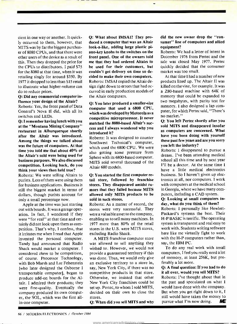
cient in one way or another. It quick- ly occurred to them, however, that MITS was by far the biggest purchas- er of 8080 CPUs, and that there were other users of the device as a result of this. Then they dropped the price for the CPUs to distributors. I paid $75 for the 8080 at that time, when it was retailing singly for around $350. By
1977 it dropped to less than $15 retail to illustrate what higher -volume can do to reduce prices. Q: Did any commercial computer in- fluence your design of the Altair? Roberts: Yes, the front panel of Data General's Nova II did, with all its switches and LEDs. Q: I remember having lunch with you at the "Montana Mining Company" restaurant in Alburquerque shortly after the Altair was introduced. Among the things we talked about was the future of computers. At that time you told me that about 40% of the Altair's sold were being used for business purposes. We also discussed competition. Looking back, do you think your views then held true? Roberts: We were selling Altairs to purists. Lots of them were using them for business applications. Business is
still the biggest market in terms of dollars, though purists account for only a small percentage now.
Apple at the time was just starting out with boards. It was a garage oper- ation. In fact, I wondered if they were "for real" at that time and cer- tainly did not look upon them as com- petition. That's why, I confess, that it irritates me when I read that Apple invented the personal computer. Tandy had announced that Radio Shack would market a computer. I
considered them to be competition, of course. Processor Technology, with Bob Marsh and Lee Felsenstein [who later designed the Osborne I
transportable computer], began to produce add -on boards for the Al- tair. I admired their products; they were fine -quality. Eventually the company produced its own comput- er, the SOL, which was the first all - in -one computer.
Q: What about IMSAI? They pro- duced a computer that was an Altair look -a -like, adding large plastic pi- ano -key knobs to the switches on the front panel. One of the owners told me that they had ordered Altairs to be used for their customers, but couldn't get delivery on time so de- cided to make their own computers. Roberts: IMSAI copied the Altair de- sign right down to errors that had oc- curred in early production models of the Altair computers.
Q: You later produced a smaller -size computer that used a 6800 CPU, which was developed by Motorola as a
competitive microprocessor. It never matched the 8080 -based Altair's suc- cess and I always wondered why you introduced it? Roberts: It was designed to counter Southwest Technical's computer, which used the 6800 CPU. We were also getting some pressure from Sphere with its 6800 -based computer. MITS sold several thousand of the Altair 680 models.
Q: You started the first computer re- tail store, followed by franchise stores. They disappeared amidst ru- mors that they failed because MITS allowed only MITS products to be sold in such stores. Roberts: As a matter of record, the stores were very successful. They were a valuable asset to the company, enabling us to sell many machines. In 1977 more than 80% of the retail stores in the U.S. were MITS stores, excluding Radio Shack.
A MITS franchise computer store was allowed to sell anything they wished to. However, we would not provide a guaranteed territory if this was done. Thus, we would only give an exclusive territory to a store in, say, New York City, if there was no competitive products in that store. Otherwise, we insisted that other New York City franchises could be set up. Pertec, to whom I sold MITS, decided on their own to close the stores. Q: When did you sell MITS and why
did the new owner drop the "con- sumer" line of computers and allied equipment? Roberts: We had a letter of intent in December 1976 from Pertec and the sale was closed May 1977. Pertec quickly decided that the consumer market was too small.
At that time I had a number of new products lined up. The Altair II was killed on the vine, for example. It was a Z80 -based machine with 64K of memory that could be expanded to two megabytes, with parity test for memory. I also designed a lap com- puter, for which Pertec said, "There's no market." Q: You left Pertec shortly after you sold MITS and disappeared insofar as computers are concerned. What have you been doing with yourself these past few years and are you sorry you left the industry? Roberts: I disappeared to pursue a dream. I've been attending medical school all this time and by next year I'll be a doctor. At the same time I
have a little medical electronics business. So I haven't given up elec- tronics at all, nor computers. I work with computers at the medical school in Georgia, where we have many com- puters, including a CAD system. Q: Looking at small computers to- day, what do you think of them? Roberts: I personally like Hewlett - Packard's systems the best. Their H -P BASIC is terrific. The operating system is transparent and real easy to work with. Students writing software here like me virtually fight to work with the H -P computers rather than, say, the IBM PC.
To do any real work with small computers, I feel you really need a lot of memory, at least 256K, but pre- ferably a lot more. Q: A final question: If you had to do it all over, would you sell MITS? Roberts: I've thought about that in the past and speculated on what I
would have done with the company. But when you get right down to it, I
still would have taken the money to pursue what I'm now doing. t
66 / MODERN ELECTRONICS / October 1984
www.americanradiohistory.com

j ELETUFJE BOOK CHUB The Best Source for Hobbyists and Professionals
for Over 18 Years!
Time- and Money- Saving Advice . . .
Practical Troubleshooting & Repair Tips . .
State -of- the -art Technology ... Hundreds of Projects ... Plus, Exceptional Savings
Select 5 Books for Only $
95
FIEEROPTIGS & wsv..m+rc ¿A _,p.lî HANDBOOK PERSONA
COMPUIFhS
List $17.95
COMPUTER
rHAT YOU CAN BUILD
1665 List $21.95
1632 List $16.95
List $19.95
` aaema r,a.4a
V1DECìCASSETT RECORDERS
1507 List $15.95
` Understanding
1531 List $17.95
RADIO
EYe.ctr©t1iC5 JMBMECüEáCEkSONS
7<,.. Ì
1671 List $21.95
TELEPHONES
1539 List $19.95
Print dv iniae At1yHa11 tfJN,
1685 List $17.95
IRIr 1ItnttftVh
t f i4(I.,ri t. Iw
1503 List $21.95
50 PRACTICAL ELECTRONIC
CIRCUITS
1537 List 516.95
MINN( I,.nmt TO
READING SCHEMATICS
1577 List $19.95
HOW TQMO
FM IBt(n ' r
5QN94101
1465 List $15.95
1536 List $14.95
1128 List $12.95 List 910.95
1499 List $21.95
I
1493 List $21.95
1473 List $19.95
rMO'& FP IIt`I I
F! 1 dJ. n. a
1451 List $18.95
MASTER HANDBOOK OF
MICROPROCESSOR CHIPS
1529 List $21.95
.TUSá$1 tt Sar,- k % ttet a>7 Oe iqn r CInetruct;un
EMI
1565 List $16.95
HALO A PERSONAL
4RT0 STATION ,. H
7O:9 WORLDWIDE SATELLITE T4. V'->
IE£HEPTIBA'
1299 1409 List $18.95
FREE When You Join Now 7 very good reasons to join the Electronics Book Club Big Savings. Save 20% to 75% on bcoks sure to increase
your electronics know -how No -Risk Guarantee. All books returnable within 10 days
without obligation Club News Bulletins. All about current selections-mains,
alternates, extras -plus bonus offers. Comes 13 times a year with hundreds of up -to- the -minute titles you can pick from
"Automatic Order." Do nothing, and the Main selection will be shipped automatically! But ... if you want an Alternate selection -or no books at all -we'll follow the instructions you give on the reply form provided with every News Bulletin
Bonus Books. Immediately get a Dividend Certificate with every book purchased and qualify for big discounts of 60% to 80%
Extra Bonuses. Take advantage of added -value promo- tions, plus special discounts
Exceptional Quality. All books are first -rate publisher's edi- tions selected by our Editorial Board and filled with useful, up -to- the -minute information
CIRCLE 26 ON
List $15.95
1113 List $12.95
VIDEO ELECTPONfCS TECHNOLOGY
1393 List $19.95
1474 List $15.95
1604 List $21.95
FREE guide to mail order sources for electronic parts and components
A $6.95 Value! -4:4.
-ffrS SIC,
ELECTFi0NJC5 Bah CLUB P.O. Box 10 Blue Ridge Summit, PA 17214
IPlease accept my membership in the Electronics Book Club and send the 5 volumes circled below, plus, my FREE copy of The Electronics Buyer's Guide, billing me $2.95 plus shipping and handling charges. If not satisfied, I may return the books within ten
Idays without obligation and have my membership canceled. I agree to purchase 3 or more books at reduced Glop prices (plus shipping/handling) during the next 12 I months, and may resign any time thereafter.
t,'
I I I I Name Phone
1113 1128 1218 1299 1337 1393 1409 1449 1451 1465 1473 1474 1493 1499 1503 1507 1529 1531 1536
1537 1539 1565 1577 1604 1632 1665 1671 1685
I Address
City
' State Zip MDNE1084 ' Valid for new members only. Foreign applicants will receive special ordering instructoons. Canada
L must remit in U S. currency. TI-is order subject to acceptance by the Electronics Book Club. ---- -------------- - ---t
FREE INFORMATION CARD October 1984 / MODERN ELECTRONICS / 67
www.americanradiohistory.com
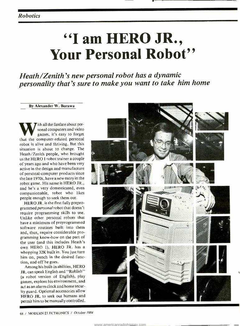
Robotics
"I am HERO JR. Your Personal Robot"
Heath /Zenith's new personal robot has a dynamic personality that's sure to make you want to take him home
By Alexander W. Burawa
With all the fanfare about per- sonal computers and video games, it's easy to forget
that the computer -related personal robot is alive and thriving. But this situation is about to change. The Heath /Zenith people, who brought us the HERO 1 robot trainer a couple of years ago and who have been very active in the design and manufacture of personal- computer products since the late 1970s, have a new entry in the robot game. His name is HERO JR., and he's a very domesticated, even companionable, robot who likes people enough to seek them out.
HERO JR. is the first fully prepro- grammed personal robot that doesn't require programming skills to use. Unlike other personal robots that have a minimum of preprogrammed software routines built into them and, thus, require considerable pro- gramming know -how on the part of the user (and this includes Heath's own HERO 1), HERO JR. has a whopping 32K built in. You just turn him on, punch in the desired func- tion, and off he goes.
Among his built -in abilities, HERO JR. can speak English and "Roblish" (a robot version of English), play games, explore his environment, and act as an alarm clock and home secur- ity guard. Optional accessories allow HERO JR. to seek out humans and permit him to be manually controlled.
68 / MODERN ELECTRONICS / October 1984
www.americanradiohistory.com

"He can sing you a song, tell you a nursery rhyme, or scare off a burglar."
Plans for marketing HERO JR. are two -pronged. Assembled units will be sold through "high- tech" de- partment stores that sell personal computers and related products and retail stores that sell computer games and software. A kit version will also be available through authorized Heath Electronic Centers and by mail order directly from the Heath factory in Benton Harbor, MI. The pricing schedule puts a $1000 tag on the wired version and about a $600 tag on the kit version.
The Externals Standing just 19" tall and weighing 21.4 lbs. HERO JR. resembles Heath's HERO 1 robot, but not too closely. HERO JR. is not a clone of HERO 1. In fact, it has been newly designed from the ground up. And since HERO JR. is meant for the home market, its design doesn't in- clude plans for retrofitting the op- tional articulated arm offered for the HERO 1 trainer robot, nor are there plans to offer a different version of the arm in the future.
Three wheels, including the steer - able wheel at the rear, give the robot its mobility. With the drive system used, HERO JR. can carry loads of up to 10 pounds on the tray built into the top of his head. Behind this tray is a slot into which optional program cartridges can be plugged.
The head section of the robot is also equipped with a 17 -key keypad that provides the means for modify- ing HERO JR's personality or initiat- ing a special task. Eight data LEDs flash in time with what HERO JR. says and indicate sound levels when he's listening.
A window for an optional infrared motion detector, an ultrasonic sonar receiver, and a light sensor make up HERO JR.'s "face." Other trans- ducers provide synthesized speech output and sound sensing.
On the rear of the head assembly are a jack for connecting the battery charger, a power switch, a sleep switch (set to sleep when the batteries
are being recharged), and an RS -232 serial computer interface connector.
Sensors For sound sensing, HERO JR. uses a pickup system with a 256 -bit resolu- tion, adjustable range, and a 200 -to- 5000 -Hz bandwidth. The robot's light sensor also has a 256 -bit resolu- tion, adjustable range, and a 25 -de- gree reception angle. The Polaroid ultrasonic sonar system can accurate- ly measure distances from 4" to about 25 ft. It's the same system Po- laroid uses in its auto -focus "One - Step" instant camera.
HERO JR's standard motion -de- tection sensor also uses his ultrasonic sonar. However, his optional six - field infrared sensor provides supe- rior heat /motion detection and im- proves his ability to seek out human company.
The speech section includes a Votrax SC -01 IC synthesizer system that offers four pitch levels and 64 phonemes. This permits HERO JR. to articulate just about any vocaliz- ing sound imaginable. The timekeep- ing system consists of a CMOS proc- essor that contains a clock with a 100 -year calendar and automatic cor- rection twice a year for Daylight Sav- ings and Standard time changes.
The RS -232 serial computer inter- face provides a convenient means for HERO JR. to accept an assembler and for loading data into and dump- ing data from memory. A HERO JR. BASIC cartridge permits programm- ing through the RS -232 interface.
Software HERO JR.'s software consists of a preprogrammed (built -in) personality that requires no user input. If you wish, however, you can shape the robot's personality by increasing or decreasing the prioriorities of each of the six personality traits. Or you can select any individual task or demon- stration mode separately.
The software program consists of four special task commands. The
"Setup" command is used for changing HERO JR.'s personality. "Guard" commands the robot to protect a specific area or to act as a se- curity device while randomly explor- ing his environment. "Alarm" com- mands HERO JR. to wake his owner at a predesigned time. And "Plan" permits you to set HERO JR. for a future activity, such as reminding you of a birthday or an anniversary.
True multitasking is built into the software programming. That is, the software permits HERO JR. to do more than one thing at a time, such as move and speak simultaneously.
Electronic Specifications HERO JR. is built around a Motorola 6806 microprocessor. He has 32K of monitor ROM, 8K of RAM and on- board provisions for up to 16K of ad- ditional RAM or ROM for future ex- pansion. Provision is also made for plugging in ROM cartridges.
Three printed- circuit cards accom- modate all the electronics. One board is for the microprocessor and ROM/ RAM system, the second is for the power supply and sensors, and the third is for the keyboard. Standard elements in the electronics package include two Motorola 6821 parallel interface adapters (PIAs) and the Motorola 146818 CMOS clock chip.
A stepper -type motor with 180 -de- gree rotation is used for steering the rear wheel, while a 12 -volt dc motor supplies the driving power that allows HERO JR. to move about. One idler wheel features an optical chopper feedback system that detects and keeps track of distance traveled. The alphanumeric keypad has clearly labeled function keys that provide access to HERO JR.'s Sing, Play, Gab, Alarm, Guard, Help, Demo, Plan, Set Up, and Enter functions.
The power supply in HERO JR. consists of two rechargeable jelled - electrolyte lead -acid batteries ("gel - cells"). Two optional batteries can
Continued on page 101
October 1984 / MODERN ELECTRONICS / 71
www.americanradiohistory.com
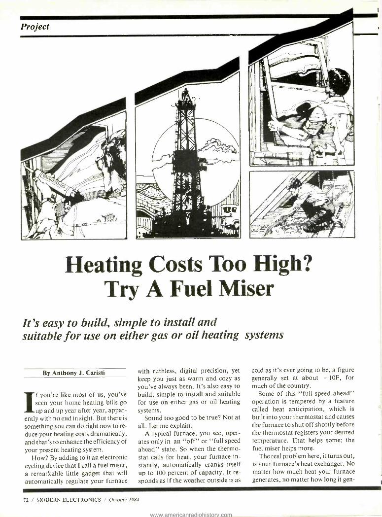
Project
Heatin g High? Costs Too Try A Fuel Miser
It's easy to build, simple to install and suitable for use on either gas or oil heating systems
By Anthony J. Caristi
If you're like most of us, you've seen your home heating bills go up and up year after year, appar-
ently with no end in sight. But there is
something you can do right now to re-
duce your heating costs dramatically, and that's to enhance the efficiency of your present heating system.
How? By adding to it an electronic cycling device that I call a fuel miser, a remarkable little gadget that will
automatically regulate your furnace
with ruthless, digital precision, yet keep you just as warm and cozy as you've always been. It's also easy to build, simple to install and suitable for use on either gas or oil heating systems.
Sound too good to be true? Not at all. Let me explain.
A typical furnace, you see, oper- ates only in an "off" or "full speed ahead" state. So when the thermo- stat calls for heat, your furnace in- stantly, automatically cranks itself up to 100 percent of capacity. It re- sponds as if the weather outside is as
cold as it's ever going to be, a figure generally set at about - 10F, for much of the country.
Some of this "full speed ahead" operation is tempered by a feature called heat anticipation, which is
built into your thermostat and causes the furnace to shut off shortly before the thermostat registers your desired temperature. That helps some; the fuel miser helps more.
The real problem here, it turns out, is your furnace's heat exchanger. No matter how much heat your furnace generates, no matter how long it gen-
72 / MODERN ELECTRONICS / October 1984
www.americanradiohistory.com

erates it, your heat exchanger can transfer just so many BTUs of heat energy jnto your hot water, steam or warm air system in a given amount of time. After the heat exchanger has reached a certain temperature level, any further burner operation simply results in more heat loss up the chim- ney. Enter the fuel miser.
It enables you to select a "duty cy- cle" for your burner that can range from 10 percent to 100 percent of ca- pacity, selectable in increments of 10 percent- nothing more. But once set, it will allow the thermostat circuit of your heating system to operate normally only for the duty cycle you have selected.
The rest of the time, your thermo- stat will be prevented from turning on your burner. However, residual heat from the heat exchanger will continue to flow into your heating
system. The on -off cycle of the fuel miser is so fast, in fact, that the heat exchanger will always have sufficient heat, just as it would with a full - speed, lower- efficiency, non -con- trolled furnace.
Gas- operated furnaces respond es- pecially well to relatively short bursts of demand. The fuel miser has thus been designed so that each 10 percent increment of heating time here is 45 seconds, with a complete cycle taking 450 seconds, or 7 Y2 minutes.
Oil furnaces are more restrictive in their cycling requirements; each sys- tem must be permitted a short cool- ing period each time the burner turns off. For oil systems then, the timing cycle of the fuel miser is set at 3 min- utes for each 10 percent increment of duty cycle. The total time for one complete cycle for an oil burner sys- tem is therefore 30 minutes.
The selection of either of these tim- ing cycles is accomplished merely by connecting one jumper wire in the fuel miser's circuit board.
How It Works As you can see from the schematic di- agram and the timing chart shown in Figs. 1 and 2, the fuel miser is simply a clock dedicated to performing a specific task.
ICI, a 555 timer chip, operates as an astable multivibrator at a frequen- cy of about 22.7 Hertz. This frequen- cy is divided by IC2, a 12 -stage binary divider, to provide a frequency of 0.022 Hertz for gas systems or 0.006 Hertz for oil systems. These frequen- cies represent periods of 45 seconds and 160 seconds (each period is the reciprocal of its frequency).
The selected output of IC2 feeds a
F1
1A
115V ac
60 Hz
Fig. 1. Schematic diagram shows that Fuel Miser is simply a clock performing a specific task.
T1
R8 10
5V o
C.2
O.1Pr a e
IC1 7
555
01
203904
R1
330K
R4 4.7K
H3 330
LED1
5V o
C1
1000 - 3FiV
CR5 = 1N5523
A GAS
OIL B
R2
100K
C3 0.4µF
2 4 13 12 14 15 1
1C2
C D4040B
11 8
MT1
Q3 T2302B
'.112
02 2N3904
100%
4 7 10 1 5
15
1C3
CD4017B
16
9 11
12
O B+
C4 0.0 1 µ F
R7
100K
October 1984 / MODERN ELECTRONICS / 73
www.americanradiohistory.com
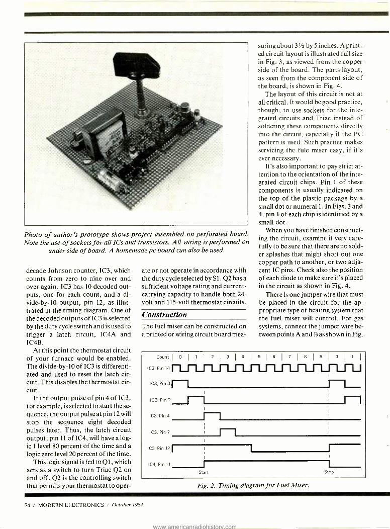
Photo of author's prototype shows project assembled on perforated board. Note the use of sockets for all ICs and transistors. All wiring is performed on
under side of board. A homemade pc board can also be used.
decade Johnson counter, IC3, which counts from zero to nine over and over again. IC3 has 10 decoded out- puts, one for each count, and a di- vide-by-10 output, pin 12, as illus- trated in the timing diagram. One of the decoded outputs of IC3 is selected by the duty cycle switch and is used to trigger a latch circuit, IC4A and IC4B.
At this point the thermostat circuit of your furnace would be enabled. The divide -by -10 of IC3 is differenti- ated and used to reset the latch cir- cuit. This disables the thermostat cir- cuit.
If the output pulse of pin 4 of IC3, for example, is selected to start the se- quence, the output pulse at pin 12 will stop the sequence eight decoded pulses later. Thus, the latch circuit output, pin 11 of IC4, will have a log- ic 1 level 80 percent of the time and a logic zero level 20 percent of the time.
This logic signal is fed to Q 1, which acts as a switch to turn Triac Q2 on and off. Q2 is the controlling switch that permits your thermostat to oper-
ate or not operate in accordance with the duty cycle selected by S I. Q2 has a sufficient voltage rating and current - carrying capacity to handle both 24- volt and 115 -volt thermostat circuits.
Construction The fuel miser can be constructed on a printed or wiring circuit board mea-
suring about 3 % by 5 inches. A print- ed circuit layout is illustrated full size in Fig. 3, as viewed from the copper side of the board. The parts layout, as seen from the component side of the board, is shown in Fig. 4.
The layout of this circuit is not at all critical. It would be good practice, though, to use sockets for the inte- grated circuits and Triac instead of soldering these components directly into the circuit, especially if the PC pattern is used. Such practice makes servicing the fule miser easy, if it's ever necessary.
It's also important to pay strict at- tention to the orientation of the inte- grated circuit chips. Pin 1 of these components is usually indicated on the top of the plastic package by a small dot or numeral I . In Figs. 3 and 4, pin 1 of each chip is identified by a small dot.
When you have finished construct- ing the circuit, examine it very care- fully to be sure that there are no sold- er splashes that might short out one copper path to another, or two adja- cent IC pins. Check also the position of each diode to make sure it's placed in the circuit as shown in Fig. 4.
There is one jumper wire that must be placed in the circuit for the ap- propriate type of heating system that the fuel miser will control. For gas systems, connect the jumper wire be- tween points A and B as shown in Fig.
Fig. 2. Timing diagram for Fuel Miser.
74 / MODERN ELECTRONICS / October 1984
www.americanradiohistory.com
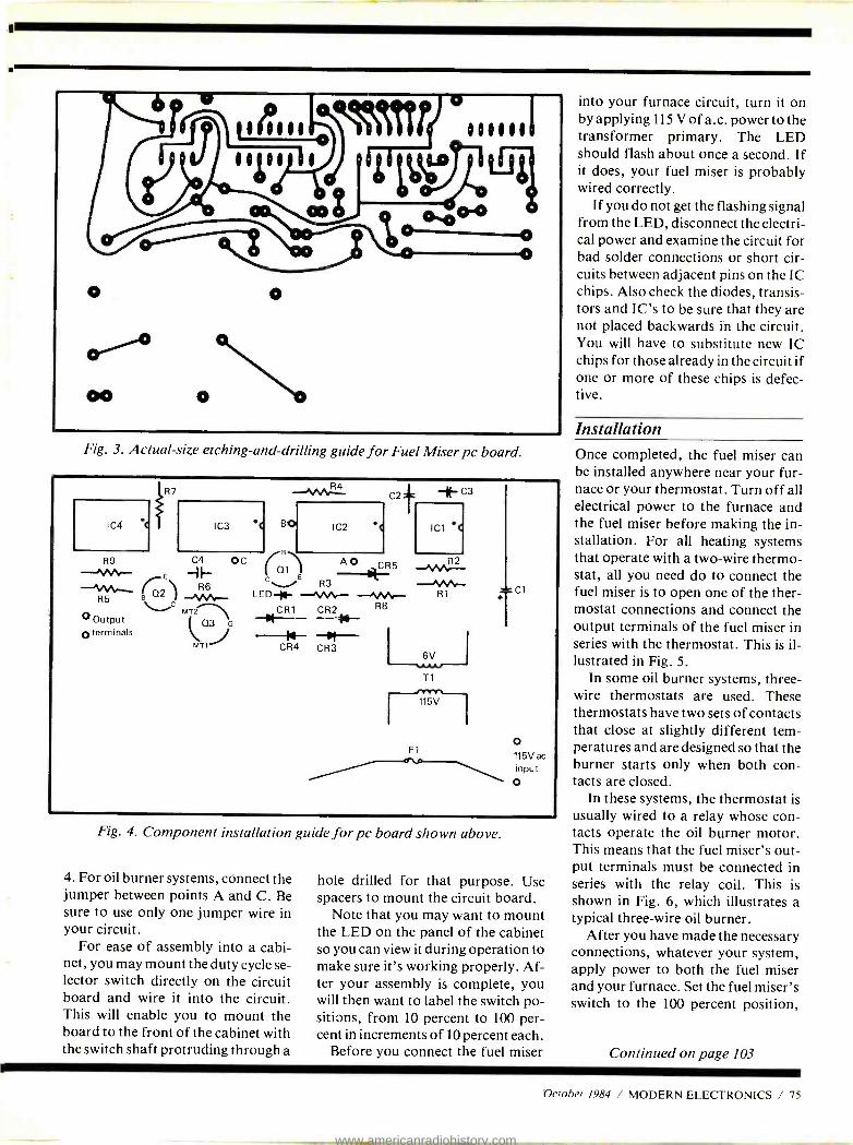
O
00
O
°d'iLU 0.. co:
Fig. 3. Actual -size etching -and -drilling guide for Fuel Miser pc board.
into your furnace circuit, turn it on by applying 115 V of a.c. power to the transformer primary. The LED should flash about once a second. If it does, your fuel miser is probably wired correctly.
If you do not get the flashing signal from the LED, disconnect the electri- cal power and examine the circuit for bad solder connections or short cir- cuits between adjacent pins on the IC chips. Also check the diodes, transis- tors and IC's to be sure that they are not placed backwards in the circuit. You will have to substitute new IC chips for those already in the circuit if one or more of these chips is defec- tive.
Installation Once completed, the fuel miser can be installed anywhere near your fur- nace or your thermostat. Turn off all electrical power to the furnace and the fuel miser before making the in- stallation. For all heating systems that operate with a two -wire thermo- stat, all you need do to connect the fuel miser is to open one of the ther- mostat connections and connect the output terminals of the fuel miser in series with the thermostat. This is il- lustrated in Fig. 5.
In some oil burner systems, three - wire thermostats are used. These thermostats have two sets of contacts that close at slightly different tem- peratures and are designed so that the burner starts only when both con- tacts are closed.
In these systems, the thermostat is usually wired to a relay whose con- tacts operate the oil burner motor. This means that the fuel miser's out- put terminals must be connected in series with the relay coil. This is shown in Fig. 6, which illustrates a typical three -wire oil burner.
After you have made the necessary connections, whatever your system, apply power to both the fuel miser and your furnace. Set the fuel miser's switch to the 100 percent position,
1C4 {
R9
R5
O Output
o terminals
7
IC3 .(
C4
E r OC
,R - IC2
2
rQ1 1 A 5 / R3 LED-*- --fs/VV-
R8 çR1 CR2
CR~ CR3
-if- C3
LJ Ti
r_Jli 5V"1
0 F 1
115V ac input o
Fig. 4. Component installation guide for pc board shown above.
4. For oil burner systems, connect the jumper between points A and C. Be sure to use only one jumper wire in your circuit.
For ease of assembly into a cabi- net, you may mount the duty cycle se- lector switch directly on the circuit board and wire it into the circuit. This will enable you to mount the board to the front of the cabinet with the switch shaft protruding through a
hole drilled for that purpose. Use spacers to mount the circuit board.
Note that you may want to mount the LED on the panel of the cabinet so you can view it during operation to make sure it's working properly. Af- ter your assembly is complete, you will then want to label the switch po- sitions, from 10 percent to 100 per- cent in increments of 10 percent each.
Before you connect the fuel miser Continued on page 103
October 1984 / MODERN ELECTRONICS / 75
www.americanradiohistory.com
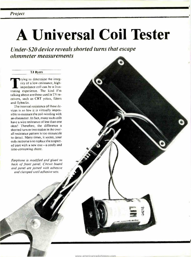
Project
A Universal Coil Tester Under -$20 device reveals shorted turns that escape ohmmeter measurements
TJ Byers
Trying to determine the integ- rity of a low- resistance, high - impedance coil can be a frus-
trating experience. The kind I'm talking about are those used in TV re- ceivers, such as CRT yokes, filters and flybacks.
The internal resistance of these de- vices is so low it is virtually impos- sible to measure the coil- winding with an ohmmeter. In fact, many such coils have a wire resistance of less than one ohm! Therefore, the difference a shorted turn or two makes in the over- all resistance pattern is too minuscule to detect. Many times, it seems, your only recourse is to replace the suspect- ed part with a new one -a costly and time -consuming chore.
Earphone is modified and glued to back of front panel. Circuit board and panel are joined with adhesive
and clamped until adhesive sets.
www.americanradiohistory.com
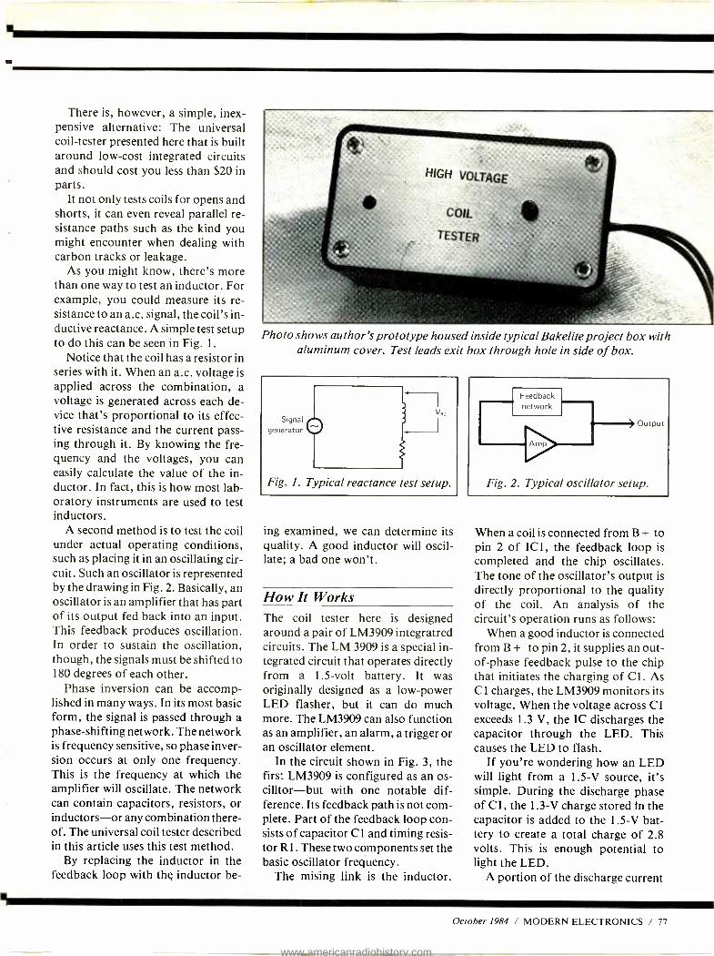
There is, however, a simple, inex- pensive alternative: The universal coil- tester presented here that is built around low -cost integrated circuits and should cost you less than $20 in parts.
It not only tests coils for opens and shorts, it can even reveal parallel re- sistance paths such as the kind you might encounter when dealing with carbon tracks or leakage.
As you might know, there's more than one way to test an inductor. For example, you could measure its re- sistance to an a.c. signal, the coil's in- ductive reactance. A simple test setup to do this can be seen in Fig. 1.
Notice that the coil has a resistor in series with it. When an a.c. voltage is applied across the combination, a voltage is generated across each de- vice that's proportional to its effec- tive resistance and the current pass- ing through it. By knowing the fre- quency and the voltages, you can easily calculate the value of the in- ductor. In fact, this is how most lab- oratory instruments are used to test inductors.
A second method is to test the coil under actual operating conditions, such as placing it in an oscillating cir- cuit. Such an oscillator is represented by the drawing in Fig. 2. Basically, an oscillator is an amplifier that has part of its output fed back into an input. This feedback produces oscillation. In order to sustain the oscillation, though, the signals must be shifted to 180 degrees of each other.
Phase inversion can be accomp- lished in many ways. In its most basic form, the signal is passed through a phase- shifting network. The network is frequency sensitive, so phase inver- sion occurs at only one frequency. This is the frequency at which the amplifier will oscillate. The network can contain capacitors, resistors, or inductors -or any combination there- of. The universal coil tester described in this article uses this test method.
By replacing the inductor in the feedback loop with the inductor be-
Photo shows author's prototype housed inside typical Bakelite project box with aluminum cover. Test leads exit box through hole in side of box.
Signal generator
Fig. 1. Typical reactance test setup.
ing examined, we can determine its quality. A good inductor will oscil- late; a bad one won't.
How It Works The coil tester here is designed around a pair of LM3909 integratred circuits. The LM 3909 is a special in- tegrated circuit that operates directly from a 1.5 -volt battery. It was originally designed as a low -power LED flasher, but it can do much more. The LM3909 can also function as an amplifier, an alarm, a trigger or an oscillator element.
In the circuit shown in Fig. 3, the first LM3909 is configured as an os- cilltor -but with one notable dif- ference. Its feedback path is not com- plete. Part of the feedback loop con- sists of capacitor Cl and timing resis- tor RI. These two components set the basic oscillator frequency.
The mising link is the inductor.
Fig. 2. Typical oscillator setup.
When a coil is connected from B + to pin 2 of IC1, the feedback loop is completed and the chip oscillates. The tone of the oscillator's output is directly proportional to the quality of the coil. An analysis of the circuit's operation runs as follows:
When a good inductor is connected from B + to pin 2, it supplies an out - of -phase feedback pulse to the chip that initiates the charging of C1. As Cl charges, the LM3909 monitors its voltage. When the voltage across Cl exceeds 1.3 V, the IC discharges the capacitor through the LED. This causes the LED to flash.
If you're wondering how an LED will light from a 1.5 -V source, it's simple. During the discharge phase of Cl, the 1.3 -V charge stored In the capacitor is added to the 1.5 -V bat- tery to create a total charge of 2.8 volts. This is enough potential to light the LED.
A portion of the discharge current
October 1984 / MODERN ELECTRONICS / 77
www.americanradiohistory.com
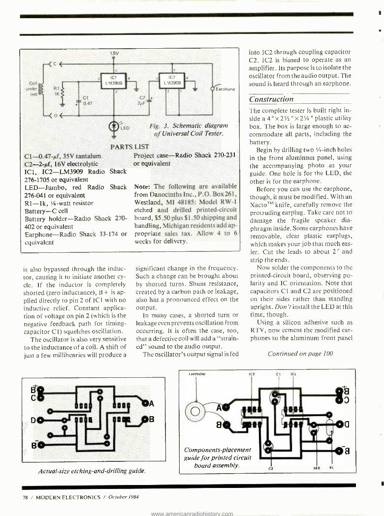
Coil under
test
1.5V o
R1
1K Cl
+ 0.47
5
1 Ic1 a
LM3909
2
C2 +
2N F
LED
PARTS LIST
C1- 0.47 -µf, 35V tantalum C2 -2 -µf, 16V electrolytic IC1, IC2- LM3909 Radio Shack 276 -1705 or equivalent LED- Jumbo, red Radio Shack 276 -041 or equivalent RI -1k, '/ -watt resistor Battery -C cell Battery holder -Radio Shack 270- 402 or equivalent Earphone -Radio Shack 33 -174 or equivalent
15
IC2
LM3909 4
Earphone
Fig. 3. Schematic diagram of Universal Coil Tester.
Project case -Radio Shack 270 -231
or equivalent
Note: The following are available from Danocinths Inc., P.O. Box 261, Westland, MI 48185: Model RW -1
etched and drilled printed- circuit board, $5.50 plus $1.50 shipping and handling, Michigan residents add ap- propriate sales tax. Allow 4 to 6
weeks for delivery.
is also bypassed through the induc- tor, causing it to initiate another cy-
cle. If the inductor is completely shorted (zero inductance), B + is ap- plied directly to pin 2 of ICI with no inductive relief. Constant applica- tion of voltage on pin 2 (which is the negative feedback path for timing - capacitor C1) squelches oscillation.
The oscillator is also very sensitive to the inductance of a coil. A shift of just a few millihenries will produce a
significant change in the frequency. Such a change can be brought about by shorted turns. Shunt resistance, created by a carbon path or leakage, also has a pronounced effect on the output.
In many cases, a shorted turn or leakage even prevents oscillation from occurring. It is often the case, too, that a defective coil will add a "strain- ed" sound to the audio output.
The oscillator's output signal is fed
-g 00
B
L-H7--Nm
o a ftlifB
Actual -size etching- and -drilling guide.
into IC2 through coupling capacitor C2. IC2 is biased to operate as an amplifier. Its purpose is to isolate the oscillator from the audio output. The sound is heard through an earphone.
Construction The complete tester is built right in- side a 4 " x 2'/2 " x 2' /a " plastic utility box. The box is large enough to ac- commodate all parts, including the battery.
Begin by drilling two '/a -inch holes in the front aluminum panel, using the accompanying photo as your guide. One hole is for the LED, the other is for the earphone.
Before you can use the earphone, though, it must be modified. With an XactoTM knife, carefully remove the protruding earplug. Take care not to damage the fragile speaker dia- phragm inside. Some earphones have removable, clear plastic earplugs, which makes your job that much eas- ier. Cut the leads to about 2 " and strip the ends.
Now solder the components to the printed- circuit board, observing po- larity and IC orientation. Note that capacitors Cl and C2 are positioned on their sides rather than standing upright. Don't install the LED at this time, though.
Using a silicon adhesive such as RTV, now cement the modified ear- phones to the aluminum front panel
Continued on page 100
EARPHONE IC C1 ICI
Components placement guide for printed circuit
board assembly. C2 L D R]
78 / MODERN ELECTRONICS / October 1984
1
www.americanradiohistory.com

MN
HB-1000 HB-0100 HB-1110
To all these add: Long Life, low resistance
and wide range contacts that accept combinations of
resistors, capacitors, diodes, ransistors, I.C.s, etc. with leads
#rom .012 - .032" or 20 - 29 AWG. Clear, easy -to- read -and- identify
contact markings simplify layout, and documentation. Socket
(rows are labeled 1 -to- 64, and columns / are marked A -to -E and F -to -J. Mating 'buss strip rows are labeled A -to -D and consist of 25 contacts each. Bold red and blue lines show where contact strips begin and end.
Finally, we have a full line of breadboard- ing equipment, from discrete sockets and buss strips to multi -board assemblies, available at comparable lower- than -low
rices.
iinirestritO
Just look at all these EXTRAS built into every HANDY test socket and buss strip...
Total contact labeling... simplifies circuit design /layout Self -adhesive backing...for one -step simplified alignment and mounting Full 9 14-Pin I.C. Capacity Expands both horizontally and vertically...interlocks can't break or twist off High temperature plastic housing... to 80° C... no warping or melting ever!
Prices always up to 25% less than other leading brands
z
Here's how to order... HANDY Sockets and Buss Strips
Part Socket Buss Ground Tie 14 pin Number Strips Strips Plate Points IC's Price
HB -0100 N/A 1 no 100 N/A 2.25 HB -1000 1 N/A no 640 9 9.95 HB -1110 1 1 yes 740 9 11.95 HB -1210 1 2 yes 840 9 13.95
HANDY Breadboard Assemblies
Part Socket Buss Binding Tie 14 pin Number Strips Strips Posts Points IC's Price HB-2112 HB-2312 HB-3514 HB-4714
2 1 2 1380 18 24.95 2 3 3 1980 18 31.00 3 5 4 2420 27 47.95 4 7 4 3260 36 63.95
Mall Orders: Please add $3 (Canada & Intl add $5) to cover cost of shipping /handling. Charge Cards: (Min. $15). Please include Acct. No.. Exp. Date. Bank No (M /C only) and your signature. Checks: Drawn in U S. Dollars on U.S. banks only. Connecticut Residents: Add 71/2%SalesTax.
To order...call 1- 800 -34 -HANDY ...charge with VISA or MasterCard. All items off- the -shelf for Immediate Shipment!
111110. vrsa
MUM
a division of RSP Electronics Corp.
7 Business Park Drive P.O. Box 699 Branford, CT 06405 (203) 488 -6603 TWX: (910) 997 -0684 Easy Link Mail Box: 62537580 CompuServe: 71346, 1070 U.S. and Canadian Distributor inquiries welcomed.
CIRCI. P 49 ON FREE INFORMATION CARI)
www.americanradiohistory.com

Project
VCR Wireless Remote Pause Control
Photograph illustrates how project neatly nests inside a plastic videocas- sette case. Note particularly details of how the photocell mounts so that
most room lighting is excluded.
By Rich Vettel
robably the most frequently used control on a video cas- sette's remote controller is the
PAUSE function. It's used to stop video recording of a TV program when the commercial goes on or when you're interrupted for one rea- son or another. If you have a wired - type remote control, and you're tired of tripping over its wire, the project presented here will delight you.
It replaces the wired control with a light- activated control unit. Using a flashlight, you can then activate and shut off the PAUSE function while anywhere in a typical room. More- over, this project does not require opening up a VCR's chassis.
How it Works When a light beam hits the photocell on the control unit, the resistance de- creases to approximately 100 ohms, applying a negative pulse to the flip - flop input. The relatively slow reac- tion time of the photocell acts as a de- bounce circuit, eliminating false trig-
80 / MODERN ELECTRONICS / October 1984
i
1
www.americanradiohistory.com
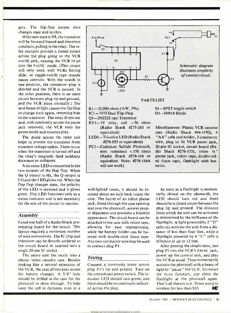
gers. The flip -flop output then changes state and latches.
If the new state is HI, the transistor will be forward biased and therefore conducts, pulling in the relay. The re- lay contacts provide a closed circuit across the plug going to the VCR PAUSE jack, causing the VCR to go into the PAUSE mode. (This circuit will only work with VCRs having slide- or toggle- switch type remote pause controls. With the switch in one position, the connector plug is
shorted and the VCR is paused. In the other position, there is an open circuit between plug tip and ground, and the VCR plays normally.) The next beam of light causes the flip flop to change state again, removing bias to the transistor. The relay drops out and, with continuity across the pause jack removed, the VCR exits the pause mode and resumes play.
The diode across the relay coil helps to protect the transistor from transient voltage spikes. These occur when the transistor is turned off and the relay's magnetic field suddenly decreases or collapses.
A tri -color LED is connected to the two outputs of the flop flop. When the Q output is HI, the Q output is LO and the LED glows red. When the flop flop changes state, the polarity of the LED is reversed and it glows green. This LED functions only as a status indicator and is not necessary for the rest of the circuit to operate.
Assembly I used one half of a Radio Shack pro - totyping board for the circuit. This layout required a minimum number of wire connections. The IC chip and transistor can be directly soldered to the circuit board or inserted into a single 20 -pin IC socket.
The entire unit fits nicely into a plastic video cassette case. Besides looking like a natural extension of the VCR, the case allows easy access for battery changes. A 5/8" hole should be drilled in the case for the photocell to show through. To help keep the cell in darkness even in a
6Vdc
NO
RY1
Nc I
1
01 PC1
GREEN
LED1
PARTS LIST
R1- 10,000 ohms ('/ W, 5 07o)
IC 1 -7473 Dual Flip -Flop Q1- 2N2222 npn Transistor RY1 -5V relay, coil >50 ohms
(Radio Shack #275 -243 or equivalent)
LED 1 -Tri -color LED (Radio Shack #276 -035 or equivalent)
PC1- Cadmium Sulfide Photocell, min. resistance < 150 ohms (Radio Shack #276 -116 or equivalent. Note: #276 -116A will not work)
Schematic diagram illustrates simplicity of control circuit.
Sl -SPST toggle switch D1 -IN914 Diode
P1
Miscellaneous: Plastic VCR cassette case (Radio Shack #44- 1192), 4 "AA" cells and holder, 2- conductor wire, plug to fit VCR pause jack, 20 -pin IC socket, circuit board (Ra- dio Shack #276 -153), inline '/ "
phone jack, velcro tape, double -sid- ed foam tape, flashlight with bat- teries.
well- lighted room, it should be re- cessed about an inch back inside the case. The barrel of an inline phone jack, fitted through the case opening and over the photocell, assures prop- er alignment and provides a finished appearance. The circuit board can be attached to the case with velcro tape, allowing for easy repositioning, while the battery holder can be fas- tened with double -stick foam tape. Any two- conductor wire may be used to connect plug P 1.
Testing
Connect a continuity tester across plug Pl's tip and ground. Turn on the control unit power switch. The in- dicator LED should turn green, and there should be no continuity indicat- ed across the plug.
As soon as a flashlight is momen- tarily shined on the photocell, the LED should turn red and there should be a closed circuit between the plug tip and ground. The distance from which the unit can be activated is determined by the brilliance of the flashlight. A light powered by 2 "D" cells can activate the unit from a dis- tance of less than four feet, while a flashlight powered by 4 "C" cells is
effective at up to 12 feet. After passing the simple tests, just
plug PI into the VCR's PAUSE jack, power up the control unit, and play the VCR as usual. Then momentarily activate the photocell with a beam of light to "pause" the VCR. To restart the PLAY function, just shine the flashlight at the photocell again. That's all there is to it. From wired to wireless for less than $10. RE
October 1984 / MODERN ELECTRONICS / 81
www.americanradiohistory.com
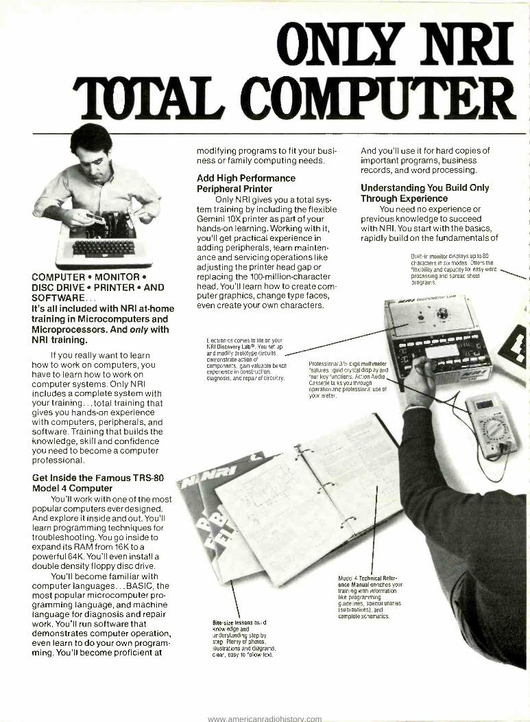
ONLY NR! IUFAL COMPUTER
AMP COMPUTER MONITOR DISC DRIVE PRINTER AND SOFTWARE... It's all included with NRI at -home training in Microcomputers and Microprocessors. And only with NRI training.
If you really want to learn how to work on computers, you have to learn how to work on computer systems. Only NRI includes a complete system with your training...total training that gives you hands -on experience with computers, peripherals, and software. Training that builds the knowledge, skill and confidence you need to become a computer professional.
Get Inside the Famous TRS -80 Model 4 Computer
You'll work with one of the most popular computers ever designed. And explore it inside and out. You'll learn programming techniques for troubleshooting. You go inside to expand its RAM from 16K to a powerful 64K. You'll even install a double density floppy disc drive.
You'll become familiar with computer languages... BASIC, the most popular microcomputer pro- gramming language, and machine language for diagnosis and repair work. You'll run software that demonstrates computer operation, even learn to do your own program- ming. You'll become proficient at
modifying programs to fit your busi- ness or family computing needs.
Add High Performance Peripheral Printer
Only NRI gives you a total sys- tem training by including the flexible Gemini 10X printer as part of your hands -on learning. Working with it, you'll get practical experience in adding peripherals, learn mainten- ance and servicing operations like adjusting the printer head gap or replacing the 100 -million- character head. You'll learn how to create com- puter graphics, change type faces, even create your own characters.
Electronics comes to life on your NRI Discovery Lab ®. You set up and modify prototype circuits, demonstrate action of components, gain valuable bench experience in construction, diagnosis, and repair of circuitry.
And you'll use it for hard copies of important programs, business records, and word processing.
Understanding You Build Only Through Experience
You need no experience or previous knowledge to succeed with NRI. You start with the basics, rapidly build on the fundamentals of
Built -in monitor displays up to 80
characters in six modes. Offers the flexibility and capacity for easy word processing and spread sheet programs.
4
Professional 31/2 digit multimeter features liquid crystal display and four key functions. Action Audio Cassette talks you through operation and professional use of
your meter.
Bite -size lessons build knowledge and understanding step by step. Plenty of photos, illustrations and diagrams, clear, easy -to- follow text.
Model 4 Technical Refer- ence Manual enriches your training with information like programming guidelines, special utilities (subroutines), and complete schematics.
www.americanradiohistory.com
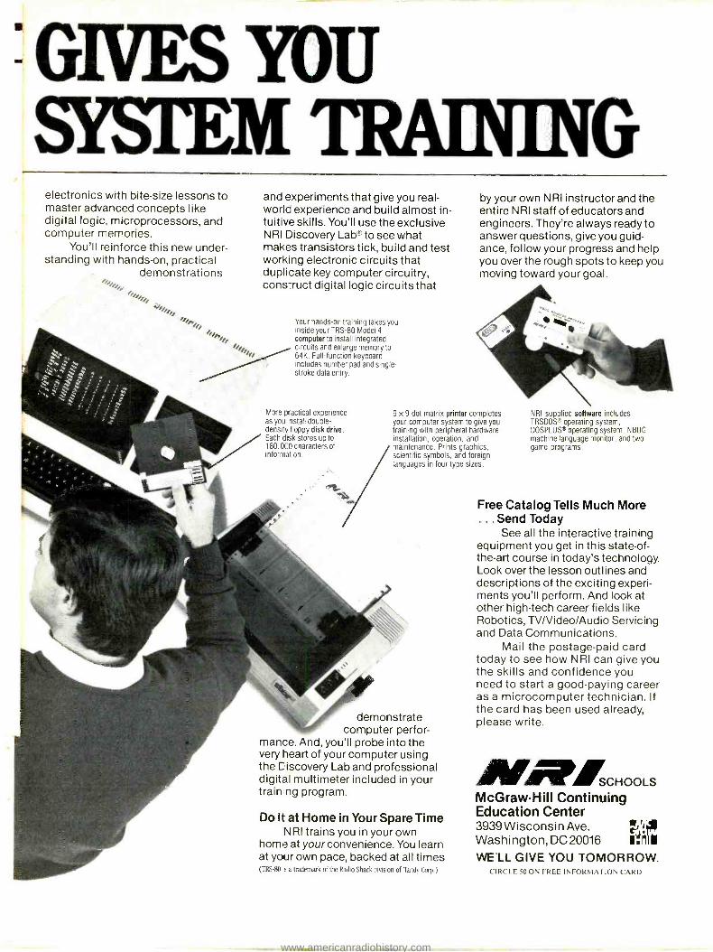
GIVES YOU SYgI'EM TRAINING
electronics with bite -size lessons to master advanced concepts like digital logic microprocessors, and computer memories.
You'll reinforce this new under- standing with hands -on, practical
demonstrations
and experiments that give you real - world experience and build almost in- tuitive skills. You'll use the exclusive N RI Discovery Lab® to see what makes transistors tick, build and test working electronic circuits that duplicate key computer circuitry, construct digital logic circuits that
Your hands -on training takes you inside your TRS -80 Model 4
computer to install integrated circuits and enlarge memory to 64K. Full- function keyboard includes number pad and single - stroke data entry.
More practical experience as you nstall double - density floppy disk drive. Each disk stores up to 180,000 characters of information.
by your own NRI instructor and the entire NRI staff of educators and engineers. They're always ready to answer questions, give you guid- ance, follow your progress and help you over the rough spots to keep you moving toward your goal.
9 x 9 dot matrix printer completes your computer system to give you training with peripheral hardware installation, operation, and maintenance. Prints graphics, scientific symbols, and foreign languages in four type sizes.
\
demonstrate computer perfor-
mance. And, you'll probe into the very heart of your computer using the Discovery Lab and professional digital multimeter included in your train ng program.
Do It at Home in Your Spare Time NRI trains you in your own
home at your convenience. You learn at your own pace, backed at all times (TRS -80 s a trademark of the Radio Shack dìsisìon of Tandy Corp . I
NRI- supplied software includes TRSDOS operating system, DOSPLUSu operating system, NBUG machine language monitor, and two game programs.
Free Catalog Tells Much More ... Send Today
See all the interactive training equipment you get in this state -of- the -art course in today's technology. Look over the lesson outlines and descriptions of the exciting experi- ments you'll perform. And look at other high -tech career fields like Robotics, TV /Video /Audio Servicing and Data Communications.
Mail the postage -paid card today to see how NRI can give you the skills and confidence you need to start a good -paying career as a microcomputer technician. If the card has been used already, please write.
MCH 00 LS
McGraw-Hill Continuing Education Center 3939 Wisconsin Ave. Washington, DC 20016
WE'LL GIVE YOU TOMORROW. ( IRCI t-suoN fRl-.r iNroRnlnrION CnRn
www.americanradiohistory.com
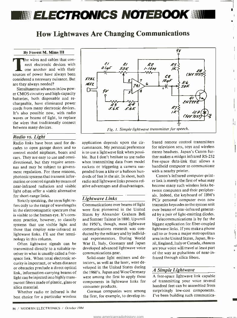
1111/,: ELECTRONICS NOTEBOOK /1//liM
How Lightwaves Are Changing Communications
By Forrest M. Mims III
The wires and cables that con- nect electronic devices with one another and with their
sources of power have always been considered a necessary nuisance. But are they always needed?
Simultaneous advances in low pow- er CMOS circuitry and high -capacity batteries, both disposable and re- chargeable, have eliminated power cords from many electronic devices. It's also possible now, with radio waves or beams of light, to replace the wires that traditionally connect between many devices.
Radio vs. Light Radio links have been used for de- cades to open garage doors and to control model airplanes, boats and cars. They are easy to use and omni- directional, but they require anten- nas and may be subject to govern- ment regulation. For these reasons, photonic systems that transmit infor- mation or control signals by means of near -infrared radiation and visible light often offer a viable alternative for short -range links.
Strictly speaking, the term light re- fers only to the range of wavelengths in the electromagnetic spectrum that is visible to the human eye. It's com- mon practice, however, to classify systems that use visible light and those that employ near -infrared as lightwave links. I'll use that termi- nology in this column.
Often lightwave signals can be transmitted directly to a suitable re- ceiver in what is usually called a free - space link. When total electronic se- curity is important, or when distance or obstacles preclude a direct optical link, information -carrying beams of light can be injected into highly trans- parent fibers made of plastic, glass or silica material.
Whether radio or infrared is the best choice for a particular wireless
.YTAL
Mr[
9V
A'? /- /ONJ
R3 .R f.6K s6.0
4;7/ tN1??
,Pj /fo
(fee- 74t7 ÿ
Fig. 1. Simple light wave transmitter for speech.
application depends upon the cir- cumstances. My personal preference is to use a lightwave link when possi- ble. But I don't hesitate to use radio when transmitting data from model rockets or triggering a camera sus- pended from a kite or a balloon hun- dreds of feet in the air. In short, both radio and lightwave links possess rel- ative advantages and disadvantages.
Lightwave Links Communications over beams of light were first pioneered in the United States by Alexander Graham Bell and Sumner Tainter in 1880. Up until the 1950's, though, most lightwave communications research was con- ducted by the military and by individ- ual experimenters. During World War II, Italy, Germany and Japan developed advanced lightwave voice communications gear.
Solid -state light emitters and de- tectors, as well as the laser, were de- veloped in the United States during the 1960's. Japan and West Germany were among the first to apply these components in lightwave links for consumer products.
German companies were among the first, for example, to develop in-
frared remote control transmitters for television sets, toys and wireless stereo headsets. Japan's Canon fur- ther makes a midget infrared RS -232 free -space data -link that allows a handheld computer to communicate with a nearby printer.
Canon's infrared computer- print- er link is merely the first of what may become many such wireless links be- tween computers and their peripher- als. Indeed, the keyboard of IBM's PCjr personal computer even now transmits keycodes to the system unit over beams of near -infrared generat- ed by a pair of light- emitting diodes.
Telecommunications is by far the biggest application for fiber -coupled lightwave links. If you make a phone call to or from a major metropolitan area in the United States, Japan, Bra- zil, England, Italy or Canada, chances are your voice will travel at least part of the way as pulsations of near -in- frared through silica fibers.
A Simple Lightwave A free -space lightwave link capable of transmitting your voice several hundred feet can be assembled from surprisingly low -cost components. I've been building such communica-
86 / MODERN ELECTRONICS / October 1984
www.americanradiohistory.com
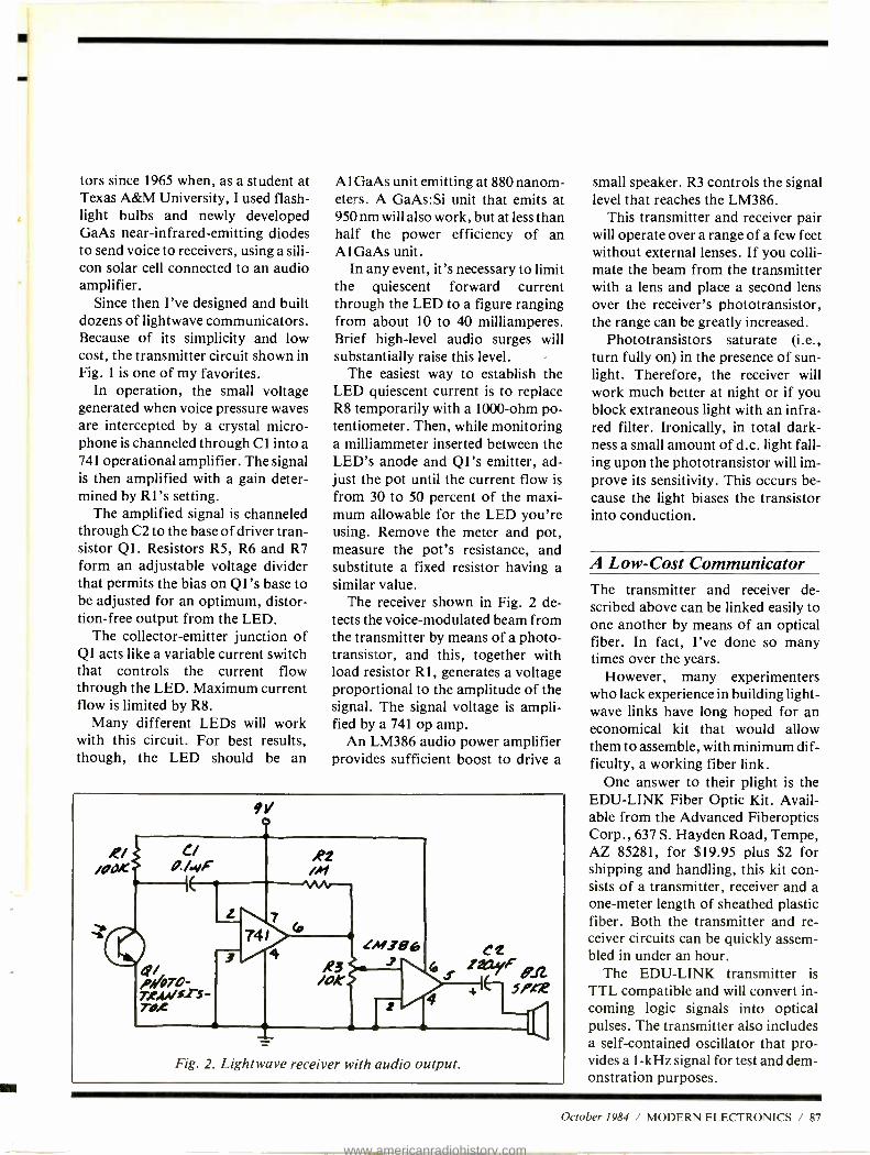
y
tors since 1965 when, as a student at Texas A &M University, I used flash- light bulbs and newly developed GaAs near -infrared -emitting diodes to send voice to receivers, using a sili- con solar cell connected to an audio amplifier.
Since then I've designed and built dozens of lightwave communicators. Because of its simplicity and low cost, the transmitter circuit shown in Fig. 1 is one of my favorites.
In operation, the small voltage generated when voice pressure waves are intercepted by a crystal micro- phone is channeled through CI into a 741 operational amplifier. The signal is then amplified with a gain deter- mined by RI's setting.
The amplified signal is channeled through C2 to the base of driver tran- sistor Q1. Resistors R5, R6 and R7 form an adjustable voltage divider that permits the bias on Q1's base to be adjusted for an optimum, distor- tion -free output from the LED.
The collector- emitter junction of Q1 acts like a variable current switch that controls the current flow through the LED. Maximum current flow is limited by R8.
Many different LEDs will work with this circuit. For best results, though, the LED should be an
A 1 GaAs unit emitting at 880 nanom- eters. A GaAs:Si unit that emits at 950 nm will also work, but at less than half the power efficiency of an A1GaAs unit.
In any event, it's necessary to limit the quiescent forward current through the LED to a figure ranging from about 10 to 40 milliamperes. Brief high -level audio surges will substantially raise this level.
The easiest way to establish the LED quiescent current is to replace R8 temporarily with a 1000 -ohm po- tentiometer. Then, while monitoring a milliammeter inserted between the LED's anode and Q1's emitter, ad- just the pot until the current flow is from 30 to 50 percent of the maxi- mum allowable for the LED you're using. Remove the meter and pot, measure the pot's resistance, and substitute a fixed resistor having a similar value.
The receiver shown in Fig. 2 de- tects the voice -modulated beam from the transmitter by means of a photo - transistor, and this, together with load resistor R1, generates a voltage proportional to the amplitude of the signal. The signal voltage is ampli- fied by a 741 op amp.
An LM386 audio power amplifier provides sufficient boost to drive a
9
Fig. 2. Lightwave receiver with audio output.
small speaker. R3 controls the signal level that reaches the LM386.
This transmitter and receiver pair will operate over a range of a few feet without external lenses. If you colli- mate the beam from the transmitter with a lens and place a second lens over the receiver's phototransistor, the range can be greatly increased.
Phototransistors saturate (i.e., turn fully on) in the presence of sun- light. Therefore, the receiver will work much better at night or if you block extraneous light with an infra- red filter. Ironically, in total dark- ness a small amount of d.c. light fall- ing upon the phototransistor will im- prove its sensitivity. This occurs be- cause the light biases the transistor into conduction.
A Low -Cost Communicator The transmitter and receiver de- scribed above can be linked easily to one another by means of an optical fiber. In fact, I've done so many times over the years.
However, many experimenters who lack experience in building light - wave links have long hoped for an economical kit that would allow them to assemble, with minimum dif- ficulty, a working fiber link.
One answer to their plight is the EDU -LINK Fiber Optic Kit. Avail- able from the Advanced Fiberoptics Corp., 637 S. Hayden Road, Tempe, AZ 85281, for $19.95 plus $2 for shipping and handling, this kit con- sists of a transmitter, receiver and a one -meter length of sheathed plastic fiber. Both the transmitter and re- ceiver circuits can be quickly assem- bled in under an hour.
The EDU -LINK transmitter is TTL compatible and will convert in- coming logic signals into optical pulses. The transmitter also includes a self- contained oscillator that pro- vides a 1 -kHz signal for test and dem- onstration purposes.
October 1984 / MODERN ELECTRONICS / 87
www.americanradiohistory.com

STATE OF THE ART KITS
EXCEL DRILL TITAN MINI DRILL $39.95 RELIANT MINI DRILL KIT 529.95 EXCEL MINI -DRILLS ARE HIGH. PERFORMANCE. COMPACT AND LIGHTWEIGHT FOR ALL THE DELICATE AND MINUTE WORK INVOLVED WITH ELECTRONICS, ENGRAVING. MODEL MAKING AND OTHER CRAFTS THE PRECI SION DESIGN MAKES THEM AS EFFICIENT
As DRILLS MANY TIMES THEIR SIZE. EACH DRILL KIT COMES COMPLETE WITH CASE AND 20 PIECE
ACCESSORY MINI TOOLS SUCH AS DRILLS. BURRS, BURCHES AND DISCS NOTE: RUNS ON 12 VOLTS D C
DRILL STAND FOR ABOVE 519.95
EXCEL PRINTED CIRCUIT BOARD KITS CIRCUIT BOARD KITS 524.95 COMPLETE KIT WITH POSITIVE RESIST PC BOARDS. ETCHANT, DEVELOPER. GRAPHICS 5 TRAY
CARBIDE P.C. DRILLS A SPECIAL PURCHASE MADE IT POSSIBLE TO PASSA SAVINGS ONTO YOU THESE DRILLS NORMALLY SELL FOR AS MUCH AS $3 95. ALL DRILLS HAVE A STANDARD 11B INCH SHANK
.033 DEC. SIZE 51.50 EA. OR 4155.00
.043 DEC. SIZE .$1.50 EA. OR 4/55.00
.OBI DEC. SIZE $1.50 EA. OR 4/55.00
LOGIC PROBE KIT ONLY 55.95 NEEDED BY ANYONE WORKING WITH LOGIC IN THEIR PRO,
JECTS. HAS A RANGE. CONSISTS OF SMALL G.10 P.C. BOARD MEASURING 2118" . 3/4" AND PRE -DRILLED. ONE SEVEN SE MENT READOUT. ONE I.C., TWO DIODES. THREE RESISTORS AND ONE TRANSISTOR. WORKS OFF 5 VOLTS AND MAY BE TAKEN FROM THE CIRCUIT BEING TESTED. INDICATES (R HIGH. IO) LOW NORMAL. AND (P) PULSING EXCELLENT STUDENT PROJECT
PRE-SCALER KITS HAL 300 PRE 514.95 PC BOARD AND ALL COMPONENTS
HAL300NPRE ..... .. ...924.95 PC BOARD AND ALL COMPONENTS WITH PRE.AMP ONBOARD
HAL IMO PRE .929.95 PC BOARD AND ALL COMPONENTS
HAL 500 AIPRE 439.95 PC BOARD AND ALL COMPONENTS WITH PRE.AMP ONBOARD
HAL 1.2 GHZ PRE .SCALER 919.95 BUILT AND TESTED . REQUIRES 5 VOLTS D.C.
SHIPPING INFORMATION: ORDERS OVER 525 WILL BE SHIPPED POSTPAID EXCEPT ON ITEMS WHERE ADDITIONAL CHARGES ARE REQUESTED. ON ORDERS LESS THAN 525, PLEASE INCLUDE ADDITIONAL 52.50 FOR HANDLING AND MAILING CHARGES. MICHIGAN RESIDENTS ADD 4% SALES TAX. SEND DO STAMP OR SASE FOR FREE FLYER.
.AP,E .ND N,HY N,N P HL , T Y ' HALTRONIX, INC. P.O. BOX 1101
SOUTHGATE. MICH. 48195 PHONE (313) 285.1182 HA1 H W4zH
HOWLAND
CIRCLE 43 ON FREE INFORMATION CAR IJ
FREE 1
1 MAIL ORDER CATALOG
1
1
1
1
1
1
1
1
1
1
Tuners, amplifiers, effects, keyboards studio equ drum corn easy to assemble kits, books & more.... name
address
I city state _ zip
1 Iniik Electronics, Inc. Dept.ME , 1020 W. Wilshire Blvd.
I Oklahoma City, OK 73116 1
800 - 654 -8657 9AM-5PM CST M -F
L - - --- - - --
1
1
1
1
1
1
1
1
1
1
1
1
ELECTRONICS NOTEBOOK
0,5E o
/
IC /A
FRS 0K
/3
/2
R4 30K
rei= cP40938E
Rb TxD S 0 0 4.7K
re /g> // /4
roc
7P/
/0
RI Jet
R2 3. 9K
2N4401
Fig. 3. TTL- compatible EDU -LINK transmitter schematic.
Fig. 3 is the transmitter's circuit di- agram. IC1 (CD4093) is a quad of two -input NAND gates, each of which exhibits Schmitt -trigger opera- tion on both inputs. Two of the gates (a and b) are connected as an astable oscillator that's enabled when the OSE (OScillator Enable) and TXD (Transmit Data) inputs are both high (logic level 1).
A third gate (c) steers the signal from the built -in oscillator or an ex- ternal source to driver transistor Q1. R2 and R3 supply base bias to Q 1,
and R1 limits the current through the LED to about 40 mA.
The LED is a Siemens GaAsP visi- ble red (665 nm) emitter. Since the re- ceiver's silicon photodiode is much more sensitive to near infrared at about 800 -950 nm, the wavelength range of the powerful near -infrared LEDs I specified for the free -space transmitter in Fig. 1, you may be wondering why the EDU -LINK transmitter uses a less powerful, red - emitting LED.
The principal reason is that plastic
ighe DI
200K
R2 4.7K
S
SV o
RIO 7
Sv
RS 4.7K
Our
R6 y. 7K VV\r--T
OfCF I 43
Fig. 4. EDU -LINK receiver accurately reconstructs incoming pulses.
i
CIRCLE 42 ON FREE INFORMATION CARD
88 / MODERN ELECTRONICS / October 1984
www.americanradiohistory.com

fibers transmit near -infrared radia- tion very poorly. On the other hand, they transmit visible red wavelengths quite well.
The simple circuit in Fig. 2 will de- tect signals from the EDU- LINK'S transmitter. The EDU -LINK receiv- er, however, employs a clever design optimized specifically for the ampli- fication and accurate reconstruction of incoming pulses.
The circuit of the EDU -LINK re- ceiver is shown in Fig. 4. ICI is an LM324N quad op amp, and D1 is a high speed PIN photodiode. In oper- ation, D1 is reverse biased and con- nected to one of the amplifiers (a) to form a voltage -to- current converter or, as it is commonly known, a trans - impedance amplifier. The operation of the remainder of the circuit is more complex than it might at first appear.
Amplifier d is connected as a unity gain follower that provides, at pin 8, a buffered version of the voltage gen- erated by the divider made from R5 and R6. Amplifier b, together with Q 1 and C 1, forms a peak detector that stores the amplitude of the in- coming pulses. According to the EDU -LINK instructions, "This stored reference signal allows one to sample the incoming signal at its point of minimum distortion, there- by reducing pulse width distortion."
The output from the peak detector is halved, relative to the reference voltage, by the divider formed from R3 and R4. This signal, along with the amplified signal from the photo - diode, is then applied to the output comparator (c).
The neatest features of the EDU - LINK kit are the plastic connectors into which the LED and photodiode are installed. Each of these connec- tors is attached to its respective cir- cuit board by a pair of mounting screws.
Only a few minutes are required to terminate the plastic optical fiber supplied with the kit. After a quarter-
inch of sheathing is removed from each end, the ends of the fiber are in- serted into plastic ferrules. The ex- posed fiber emerging from the end of each ferrule is then cut with a hobby knife. The link between transmitter and receiver is completed when the plastic ferrules at each end of the fi- ber are snapped into the LED and photodiode connectors.
All that's necessary to test the link is a 5 -volt power supply and an audio amplifier or oscilloscope. I powered the unit I assembled with a pair of 6 -volt batteries. (I dropped the volt- age from the transmitter battery to about 5.4 volts by connecting a 1N914 diode between the positive battery terminal and the circuit.)
You can hear the test tone by con- necting the output from the receiver to a small audio amplifier. Or you
can monitor the signal with an oscil- loscope as described in the instruc- tions supplied with the kit.
Going Further If you would like to learn more about lightwave communications, you may want to read my book, A Practical Introduction to Lightwave Commu- nications (Howard W. Sams, 1982). For a variety of both amplitude and pulse -modulated circuits, see The Forrest Mims Circuit Scrapbook (McGraw -Hill, 1983).
In the meantime, be sure to stay tuned. Along with many other topics to be covered in "Electronics Note- book," I'll include additional tips on free -space and optical fiber light - wave communication circuits in fu- ture columns.
Quick charge cordless scldering iron. Up tc 125 electronics joints pe- charge. Total recharge in less then 4 hours. Isolated tip design. One of more than 2 dczen ISO -TIP an i ORYX irons available. Write for free catalog and name of nearest d stributor
A Hot Tip on Cordless Soldering
No. 7700 QUICK CHARGE
Cordless Soldering Iron
IS TIP ORYX"
WAHL CLIPPER CORPORATION S-erling, Illino s 61381 (81e) o25.6525
CIRCLE 15 CN FREE LJFORMATION CARD October 1984 / MODERN ELECTRONICS / 89
www.americanradiohistory.com

1E11111 COMMUNICATIONS IN
50 Countries For Shortwave Listening
By Glenn Hauser
The world is on the air. Yet, most Americans are blissfully unaware that there's a gaping
chasm between the frequency bands on their radios, where international shortwave broadcasting takes place. Much of it is especially beamed to North America, in English. Now it's easier than ever to get a shortwave radio with digital- frequency readout, even keyboard entry, so that once you have access to the broadcast times and frequencies as presented here later, it's a simple matter to ex- pand your radio listening horizons beyond your local stations to the countries of your choice.
Keep in mind some important dif- ferences between international and local radio. Shortwave stations sel- dom have only one frequency they use all the time. Nor can you neces- sarily hear them at any hour of the day or night. With a few exceptions, English broadcasts typically last one hour or half an hour, perhaps aired twice each evening for eastern and western time zones. Frequencies change, too, from time to time, de- pending on the sunspot cycle, the sea- son of the year, time of day, and in- terference. Stations seldom change all their frequencies at once, so be sure to try all frequencies we men- tion, and listen for announcements; changes are sometimes made with lit- tle or no advance notice. Further- more, if you don't hear a certain sta- tion the first time you try, don't give up. Reception conditions can vary drastically from one day to the next, since shortwave signals come to us via the fluctuating ionosphere.
In general, European and African stations are heard better in eastern North America, while Asian and Pa- cific stations are received better in the west, but there is a great deal of over- lap. More and more stations are es- tablishing relay bases in Latin
RADIO FREE EUROPE - RAUIO 1.11iLR
M:<)NI7C tlt I A°, I?:MN PL HOP
Radio Free Europe /Radio Liberty sends out this QSL to interested
listeners.
America to improve reception relia- bility throughout North America.
Among the first things shortwave listeners must learn is the 24 -hour UTC time system. Once you know how Coordinated Universal Time re- lates to your local clock, you won't have to bother with converting times or figuring out what time it is in the originating country. During DST, until the last Sunday in October, UTC is 4 hours ahead of EDT, 5
hours ahead of CDT, 6 hours ahead of MDT, 7 hours ahead of PDT, and so on. And the next day of the week starts the previous evening in North America. So to convert UTC to local time, subtract the appropriate num- ber of hours. If the result is still 1300 or higher, you want to use the 12- hour clock, subtract another 12
hours and call it p.m. For example: in Denver, when would you listen for a broadcast at 2300 UTC? 23 minus 6 is
17; 17 minus 12 is 5 p.m. MDT. Once you're familiar with the system, you won't even have to think about con- verting- you'll know that 9 p.m. MDT is the same as 0300 UTC the next day.
Ready? Let's go through the al- phabet with a sampling of what's to be heard on shortwave -in English unless otherwise specified. Broadcast frequencies are noted after the UTC time in kiloHertz. To convey to
megaHertz, simply move three deci- mal places to the left (thus, 9750 is 9.750 megahertz (MHz).
Albania. Let's plunge right into the culture shock of Radio Tirana, the "Voice of Marxism -Leninism," at 0000 -0025 on 9750 and 7065; 0130 -0155 and 0230 -0255 on 9750 and 7120; and 0330 -0355 on 7300 and 6200. Frequencies vary up to ± 5
kHz. Algeria. Radio Algiers punctuates
its newscasts with musical stingers. Listen at 2000 -2030 on 17745, 15215, 9685, and do not believe this station's frequency announcements.
Argentina. RAE can be heard best when southern conditions are "up," and northern conditions are "down" -at 0200 -0300 on 11710 and 15345.
Australia. Despite its great dis- tance, ABC's station in Perth, in- tended to cover the Outback, puts a good signal into North America at 1000 -1600 on 9610. Even more reli- able is the overseas service, Radio Australia, from Melbourne. Main frequency is 9580 between 0800 and 1400. Many others are announced each half hour. After 0200 UTC try 15320 and 15395. Unlike the United Kingdom's BBC, Radio Australia has news on the hour every hour; there's lots of pop music and, especially on weekends, feature programs.
Austria. The Austrian Radio, ORF, has a polished and cultured pro- gram well worth hearing, at 0130- 0155 and 0330 -0355 on 5945 and 9770; 0430 -0455 on 5945 and 11665; 1230 -1255 on 15320. The 0330 and 1230 broadcasts start 25 minutes earlier on UTC Sundays. "Shortwave Panorama" appears on the Sunday 1230 and UTC Monday 0430 trans- missions. If you listen before and after the times given, you'll hear ORF mostly in German with lots of fine music from folk to classical.
Belgium. BRT broadcasts at 0030- 0115 on 9925 and 11620, repeated Mon. -Fri. at 1400 -1445 on 17610.
90 / MODERN ELECTRONICS / October 1984
www.americanradiohistory.com
Brazil. RNB, Brasalia coinciden- tally competes with Argentina, also in English, at 0200 -0300 on 15290, but generally has a better signal. The emphasis here is on music.
Bulgaria. Radio Sofia can be heard at 2130 -2200 on 11850, 11750 and 9700; 2230 -2330 and 0000 -0100 on 11870 and 9700; 0400 -0500 on 11750.
Canada. Radio Canada Interna- tional is easily audible here whether broadcasting to Europe, Africa, the Caribbean or the U.S.A., both with its own programs and relays from the domestic CBC Radio. "Sunday Morning" is an excellent review of the week's world and Canadian events, at 1310 -1600 on 17820 and 11955. A widely respected and thorough evening newscast is "The World At Six" at 2200 -2230 Mon. - Fri. on 15325, 11960, 9755 and 5960, and at 0100 -0130 on 9755 and 5960. RCI's own programs include broad- casts at 0000 -0030, 0200 -0230 and 0300- 0330 on at least 5960 and 9755. The middle program UTC Mondays carries "SWL Digest," which will help you update information here. Private low- powered shortwave sta- tions CFCX in Montreal on 6005, and CRFX in Toronto on 6070 repre- sent the only signals to be heard in the daytime on 49 meters in the north- eastern U.S.
China. Radio Beijang is our major window on this country, and is quite responsive to listeners. Tune in at 1100 -1155 on 15520; 1200 -1255 on 15520 and 11650; 0000 through 0455 on two or three of: 17795, 15520, 15385.
Cuba. Radio Havana Cuba is too close to be heard well in Florida (its higher shortwave frequencies skip over) but it's regular in more distant parts of North America; program cycles are basically a sesquihour long, whatever the lengths of trans- mission may be: 2010 -2140 on 17885; 2050 -2140 on 17750, 17705; 0100 -0450 on 11930, 15300; 0330-
0600 on 11760; 0450 -0600 on 15300; 0630 -0800 on 11725. At other times of day, 17750, 17705, 11760 and several others are in Spanish with lots of good music.
Czechoslovakia. Radio Prague gives you two chances to hear the same program -0100 -0155 & 0300- 0355 on 11990, 9740, 9540, 7345, 5930.
Egypt: Radio Cairo is a very low - key station, making us suspect the wee hours over ther during the 0200- 0330 broadcast are taking their toll; on 9475 and 9675.
Finland. Radio Finland battles BBC /Ascension on 15400, and Deutsche Welle on 17800, but some- times they come out on top -at 1100- 1125, 1200 -1225, 1300 -1325 and 1400 -1425; except Sundays when "Sunday Best" repeats the best of the preceding week at 1230 -1425.
France. R. France International still restricts English to Africa, but fortunately we can hear it without too much trouble. At 1605 -1655 on 15315 and 17620; 0315 -0330 and 0345 -0400 on 15440 and 15180 (via French Guiana), 9790 (via Gabon), 9550, 9545, 7135 (direct); and at 0415 -0430 & 0445 -0500 on 15155, 11995, 11875, 11705, 9790, 9550, 7135.
Germany, East. Radio Berlin In- ternational is heard best with pro- grams for Africa beamed to the Caribbean, at 2215 -2300 on 9620 and 9600; 0200 -0245 on 9620. Also try the Western North America ser- vice (even in the East) at 0230 -0315 and 0530 -0615 on 9560, 11975. All these shift an hour later from the last Sunday in September.
Germany, West. Radio Deutsche Welle, the Voice of Germany, is a bit heavy on politics, but at least not the leaden East German variety. Several relay bases assure reliable reception. At 0100 -0150, Malta on 11785, 9590 and 6085; Antigua on 9545 and 6040; direct on 9565 and 6145. At 0500-
0550 via Antigua /Montserrat on 11705 and 9545; direct on 9690, 6120, 5960 (subject to change). DW has a more extensive schedule of German - language broadcasts, repeating in 4- hour cycles throughout the daytime and nightime hours.
Greece. Voice of Greece broad- casts more than five hours a day to North America, mostly in Greek with lots of music, but with English news at 1235 and 1540 on 9815, 11645, 15635;0130 and 0340 on 9420, 9865, 11645.
Guyana. You may well overlook GBC unless you're a night owl. It's on 5950 from around 0730 until local sunrise fades it out. Listen for the "Early Birdie Show."
Hungary. On any given night, the two Radio Budapest broadcasts have different content: 0100 -0139 (except UTC Mondays), and 0200 -0230 (dai- ly) on 12000, 11910, 9835, 9520, 6025.
Indonesia. Voice of Indonesia is on 11790 at 1500 -1600; best in the West.
Iran. Voice of the Islamic Republic of Iran is at 1930 -2030 on 9022 and 11930- reception is difficult.
Iraq. Radio Baghdad uses 9610 at 2030 -2125; one hour later in the winter.
Israel. Israel Radio, when its jour- nalists are not on strike, is heard very well at 0000 -0030, 0100 -0125 and 0200 -0225 on 11655, 9815, 9440 (one hour earlier during summer time). Also at 0500 -0515 on 11655 and others.
Italy. RAI has a token English ser- vice with dreary news and music fill at 0100 -0120 on 11800 and 9575.
Japan. Radio Japan is planning a relay in Panama; until then it's spotty except along the West Coast, though the Gabon relay helps some. Hour broadcasts are at 0500 on 15300; 0700, 1300 and 1500 on 9505; 1500 on 21695 (Gabon); 0000 on 17825, 15300; 0145 on 21640, 21610, 17825,
October 1984 / MODERN ELECTRONICS / 91
www.americanradiohistory.com
COMMUNICATIONS . .
A bumper sticker from Super Rock station KYOI in Japan.
15195. And for half an hour at 0900 and 1100 on 9505.
Korea, North. Radio Pyongyang is
always deep in the mire of the per- sonality cult of Kim -Il Sung, but it
can be amusing for a while -1100- 1250 on 9977 and 9745.
Korea, North. Radio Korean often sounds American, but has its own hard line to follow, in a country where people owning shortwave radios are suspected of being spies. Hour -long programs are at 0145 on 15575; 11810; 0330 on 15575, 18820, 9570; 1100 on 15575; 1400 on 15575, 9750, 9570; 1600 on 11810, 9870. Quarter hour news is at 1715 and 1745 on 15575; 2345 on 7550 and 15575; 0815 and 0845 on 9570; 1345 on 15575.
Libya: Radio Jamahiriyah is
rather slipshod in its timing, approx- imately 1800 -1930 on 15450 and 2130 -2300 on 11815; about one hour later from Oct. 1. Listening to it might change your conception of Murmar Qaddhafi.
Mongolia. We include this diffi- cult -to -hear station for the sake of exotica: Radio Ulan Bator, Mon. - Sat. at 1200 -1235 in 12015.
Netherlands. Radio Netherlands is
highly reliable, thanks to its Bonaire relay; new 500- kilowatt transmitters in Holland are coming on this year, and changes in program timing and content are expected. Listen at 1030-
1125 in 9650; 2030 -2120 on 17605, 15560, 11730, 9715 9540 (the last two via Madagascar); 0230 -0325 on 9590, 6165; 0530 -0625 on 9715, 6165. During the last two, 9895 has been testing direct from Holland.
New Zealand. Though low- power- ed at 7'h kW, Radio New Zealand is
worth seeking out for its home ser- vice relays. Before 0330 try 17710, afterwards 11960 until 1215; before 0530 try 15485, afterwards 9620 until 1215.
Nicaragua. Voice of Nicaragua seems to be patterned after Radio Habana Cuba, but unlike it, hardly a broadcast goes by without several an- nouncements deliniating the pro- cedure of American to Nicaragua. At 0100 -0200 and 0400 -0500 on 6017.5; could change back to former fre- quencies of 6100 or 5950, or move again.
Nigeria. Voice of Nigeria has three separate English programs at 0500, on 7255, 15119 and 15185; at 0530 they merge for a common newscast.
Poland. Radio Polonia is at a dis- advantage because of low power and geographical position in northeast- ern Europe (so more of its signal has to pass through the auroral zone); keep trying at 0200 -0355 on 15120, 11815, 9525, 7270, 7145, 6095.
Portugal. By contrast, Radio Port- ugal can generally be heard further west, and holds up longer during propagational disturbances owing thanks to its favorable location in southwestern Europe -0300 -0330 on 11925 and 6060; 0530 -0600 on 9575 and 6075. It it's missing from one of these channels, mix up the numbers and try again -like 6750.
Romania. Radio Bucharest has two separate programs at 0200 -0255 and 0400 -0430, but both on 11940, 11830, 11810, 9570, 9510, 6155, 5990.
South Africa. Radio RSA is an- other station with a western sound, but a peculiar line to propagate. Listen at 2100 -2157 on 11900 and
9585; 0200 -0257 on 9615, 6020, 5980. Spain. Spanish Foreign Radio is
one the brighter voices in western Europe, but sometimes suffers from too -literal translation from Spanish. At 0000, 0100, and 0500 on 9630 and 11880.
Sweden. Radio Sweden has recep- tion like Finland and Poland, but do give it a try, especially on Tuesdays for "Sweden Calling DXers " -at 1400 -1430 on 15190; 2300 -2330 on 11710 and 9695; 0230 -0300 on 11705 and 9695.
Switzerland. Swiss Radio Interna- tional concentrates on current events, weekdays; feature programs on week- ends, with a generally reliable signal, now that it's out of band, even though lacking relays. At 1315 -1345 on 17765; 1815 -1845 on 12035; 2145- 2215 on 9885, 12035, 15570; 0145- 0215 on 12035, 9885, 9725, 6135; 0430 -0500 on 12035 and 9725.
Taiwan. Voice of Free China still broadcasts direct, but reception is so much better via relays in Florida: 0100 -0200 and 0150 -0610 on 5985; one hour later after DST.
Turkey. Voice of Turkey is an- other station enjoyed for its music; preoccupation with the Aremenian question mars its talk portions. Listen at 2200 -2250 & 0300 -0350 on 11755.
United Arab Emirates. UAE Ra- dio, Dubai, is putting this Gulf state on the map with unbiased news and features on Arab culture, at 0330- 0400 or later on 17775, 15430, 11730.
United Kingdom. If you listened to no other shortwave station besides BBC World Service, your purchase of a shortwave radio would still be a bargain. BBC serves all tastes in music, has the world's most reliable and respected news (most hours on the hour), and eclipses all other stations, including VOA, in its entertaining and informative feature programming. Though on the air 24 hour, only cer- tain times are received well in North
92 / MODERN ELECTRONICS / October 1984
www.americanradiohistory.com

America. At 1100 -1330 on 15215-di- rect, 11775- Antigua, 5965 -Sackville, Canada; 1300 -1330 also on 9510 - Sackville; 1330 -1600 on 21600 -As- cension; 1600 -1709 (1500 -1745 on weekends) on 15260 and 11775 (both Sackville); 2000 -2430 on 15070 -di- rect; 2200 -2430 on 9590 -Sackville; 2300 -0330 on 9915, 7325, 5975 (all direct), 6175- Antigua; 0330 -0730 on 6175 -Antigua; 0430 - 0915 on 9510 - Antigua. To keep track of BBC pro- grams and their repeat cycles, you'll need a detailed schedule which ap- pears in Review of International Broadcasting.
United Nations. UN Radio now has Monday- Friday broadcasts; dur- ing other times of the year when the General Assembly is not in session, it cuts back to once a week on Fridays. Facilities of VOA are used. 1930 -2000 on 2170, and 15120; on SSB via 20060 and 18782.5. At 2100 -2145 on 17730 and 15120.
U.S.A. With its reliance on over- seas relays, Voice of America is not the cinch to hear in the daytime you might think. At 1100 -1330 try the Philippines on 9760 and 11715. At 1600 -2300 tune the African service via liberia on 15600. No problem at night, with U.S. transmitters serving Latin America at 0000 -0400- 17730, 15375, 15205, 11740, 9650, 9455, 6130, 5995. During the first half hour or so, 9455 and 6130 are separate with Caribbean programs.
WRNO. New Orleans, has a peak signal toward Montreal, but recep- tion is good in most parts of North America except the extreme south- west and southeast. On weekdays be- tween 1700 and 0500, transmissions have been originating from the World's Fair site. WRNO has one transmitter, changing frequencies as follows -1700 -2200 on 15420, 2200- 0100 on 9705, 0100 -0300 on 7355, 0300 -0500 on 6185. Rock music is the format, except for lengthy blocks, especially on weekends, with relig-
Here is a very attractive QSL issued by Radio Korea.
ions programs in a variety of lan- guages and two programs of special interest, "World of Radio," in which you are kept up to date on developments in international broad- casting, UTC Saturdays 0430 on 6185 repeated UTC Sundays 0130 on 7355 and 1300 on 9715; and "The World" from Radio Earth, an inde- pendent station buying time from WRNO, nightly at 0300 -0400 on 6185. Radio Earth is a commercial entity hoping to set up its own trans- mitter; dedicated to giving shortwave listeners the programming and per- sonalities they enjoy most, and in great variety; musical emphasis is Caribbean with Rudy Espinal in San- to Domingo.
AFRTS operates 22 hours a day in a never- ending cycle of mostly de- commercialized network radio news and features. It's a good way to keep up with domestic U.S. radio in re- mote areas of our own country, and the only way to do so overseas. AFRTS also carries the two major news vehicles of National Public Radio, minus local interruptions so many other affiliates insert- "Morn- ing Edition" at 1000 -1200 Mon. - Fri.; and "All Things Considered" at 2100 -2230. But sports always comes first at AFRTS, with a heavy schedule of play -by -play coverage pre -empting anything in its way; plans are announced in advance
Mon. -Fri. at 1735 and Tue. -Sat. at 9535. All UTC times are none hour later after DST. Exact times of fre- quency vary from season, but this was the summer lineup: 0900 -1100 on 9590; 0900 -1200 on 6030; 1100- 1700 on 15430, 15330, 11805, 9700; 1700 -1800 on 15430, 15345, 15330, 9700; 1800 -2200 on 17765, 15430, 15345, 15330; 2200 -2300 on 21570, 17765, 15430, 15345, 15330; 2300- 0100 on 21570, 17765, 15430, 15330, 11790; 0100 -0200 on 21570, 17765, 15330, 11790, 6030; 0200 -0430 on 21570, 17765, 11790, 6030; 0430- 0700 on 17765, 15330, 11790, 6030.
U.S.S.R. Radio Moscow likes to use a dozen frequencies at once, or even more -and believe it or not, be- cause of the polar path, sometimes only one or none make it through. But the Havana realy is extremely re- liable propagationally, although au- dio quality can be quite poor. This is on 11840 between 1000 and 2200; 9600 at 0000 -0500. Tune around the 11- and 9 -MHz bands at 2200 to hear Radio Moscow's opening frequency announcements, which you can fol- low throughout the evening. If you look for them, you'll find programs about Soviet culture; without look- ing, you'll always be made aware of the party line. Between 2200 and 0700 there are only two hours of original programming that is repeated over and over.
Several regional Soviet station also broadcast in English, not necessarily from within their own borders.
RCTVDubai's location is on its QSL.
October 1984 / MODERN ELECTRONICS / 93
www.americanradiohistory.com

New Television Converter Book
VIDEO
SCRAMBLING
TECHNIQUES
ACCESS
CIRCUITS, THEORY, WAVEFORMS, Subscription TV Reference Manual
This information packed book de- tails the methods used by subscrip- tion TV companies to scramble and descramble video signals. Covers the Sinewave, Gated Pulse, SSAVI system, and the methods used by most cable companies. Includes circuit schematics, theory, wave- forms and trouble shooting hints. Only $12.95 plus $2.00 first class P
& H. Information $2.00, refundable. Foreign orders please remit in U.S. funds only.
RANDOM ACCESS Box 41770 -G, Phoenix, AZ 85080
( I R l I I :- I)C I RI I I \ I UI.AI A I IU\ ARI)
Radio Kiev is on at 2330 -2400 on 17860, 15405, 15180, 11720, 9800, 9688; at 0200 -0230 on 17860, 15405, 15180, 11720, 9800; Radio Vilnius at 2200 -2230 mostly on the same fre- quencies at Kiev's first broadcast; Radio Yerevan at 0253 -0256 (the shortest daily English broadcast to North America) on 17860, 15405, 15180. In all cases, these three fre- quencies are from the Soviet Far East; the lower ones from Europe. Radio Tashkent broadcasts direct from Uzbekistan for an evening au- dience in India, but we're off the back in the morning -at 1200 -1230 and 1400 -1430 on 15460, 11785, 9715, 9650, 7340. All except Tash- kent and the World Service shift one hour later Oct. 1, with frequency changes too.
Vatican. Overlapping RAI's Eng- lish broacast, Vatican Radio is usual- ly more interesting, at 0050 -0110 on 11845, 9605, 6015.
Yugoslvia. Radio Yugoslavia can
be heard at 2115 -2130 on 9620; one hour later from October.
There are many other English
QSL of Ecos del Torbes of Venezuela.
broadcasts beyond these 50 coun- tries, but reception is generally more difficult. We've also omitted here missionary stations, some with very strong signals, which are devoted to propagating Christianity rather than the culture of their host country. We already have plenty of gospel broad- casting on local radio. RE
Computer problems?
DON'T BLAME THE SOFTWARE! Isolators prevent:
CPUlprinter /disk interaction Lightning or spike damage AC power line disturbances RFI -EMI interference
Pat. # 4,259,705
Commercial Grade Isolators ISO -1 3 Isolated Sockets ISO-2 2 Isolated Socket Banks, 6 Sockets
Industrial Grade Isolators I50 -3 3 Double Isolated Sockets ISO -11 2 Double Isolated Banks, 6 Sockets
Laboratory Grade Isolators ISO- 17 4 Quad Isolated Sockets ISO -18 2 Quad Isolated Banks, 6 Sockets
Circuit Breaker, any model (Add -CB)
Remote Switch, any model (Add -RS)
$ 81.95 $ 81.95
$122.95 $122.95
$213.95 $180.95
Add $ 11.00 Add $ 20.00
AEZ Electronic Specialists, Inc. 171 S. Main St., Box 389, Natick, Mass. 01780 (1317) 855.1532
Toll Free Order Desk 1- 800 -225 -4878 MasterCard, VISA, American Express
CIRCLE 46 ON FREE INFORMATION CARD
94 / MODERN ELECTRONICS / October 1984
COUNTRIES USING U.S. VIDEO STANDARD With the advent of small, lightweight TV receivers, international travellers might think they can carry one of them and simply plug it in to the foreign country's a.c. outlet to get local television recep- tion. One can't be assured of this, of course, since many countries have different electricity standards. Furthermore, even video for- mats aren't standardized, so battery -powered models may not work either.
Though many countries do use the U.S.'s NTSC video standard (525 -line system with 110 V /60 Hz electric power), many others em- ploy the PAL standard (625 -line system on 220 V /50 Hz) or SECAM (another 625 -line system used in the U.S.S.R., among other coun- tries). Obviously, a TV receiver designed to receive one video sys- tem's transmissions cannot operate with another broadcast stan- dard.
Here is a listing of the countries that do indeed use the same video standard as in the U.S. Note that Europe is not the place to take along your U.S. TV portable.
Azores Bahamas Barbados Bermuda Canada Chile Columbia Costa Rica Cuba Curacao Dominican Rep. Ecuador
EI Salvador Philippines Greenland Puerto Rico Guam Samoa Guatemala St. Kitts Honduras Surinam Japan Taiwan So. Korea Trinidad Mexico Tobago Antilles Venezuela Nicaragua Vietnam Panama Virgin Is. Peru
As previously cited, the three major color TV standards in the world are not compatible with each other. This was true at the onset of black -and -white TV, when two different systems were developed.
These same standards were carried over when color TV systems were adopted by respective countries. The two systems emerged as the U.S.'s NTSC (National Television Systems Committee) and the PAL (Phase Alternate By Line) designed by Germany's Telefunken. A third major color video system, designed in France, is SECAM (Sequential with Memory).
www.americanradiohistory.com

NEW! UD1EIE!fl® Aonwcnt
Products Communications Electronics;
the world's largest distributor of radio scanners, is pleased to announce that Bearcat brand scanner radios have been acquired by Uniden Corp- oration of America. Because of this acquisition, Communications Elec- tronics will now carry the complete line of Uniden Bearcat scanners, CB radios and Uniden Bandit radar detectors. To celebrate this acqui- sition, we have special pricing on the Uniden line of electronic products.
Bearcat°300 -E List price $549.95/CE price $339.00 7 -Band, 50 Channel Service Search No- crystal scanner AM Aircraft and Public Service bands. Priority Channel AC /DC Bands: 32 -50, 118 -136 AM, 144 -174, 421 -512 MHz. The Bearcat 300 is the most advanced automatic scanning radio that has ever been offered to the public. The Bearcat 300 uses a bright green fluo- rescent digital display, so it's ideal for mobile applications. The Bearcat 300 now has these added features: Service Search, Display Intensity Control, Hold Search and Resume Search keys, Separate Band keysto permit lock -in /lock -out of any band for more efficient service search.
Bea rcat° 20/20-E List price $449.95/CE price $269.00 7 -Band, 40 Channel Crystalless Searches AM Aircraft and Public Service bands AC /DC Priority Channel Direct Channel Access Delay Frequency range 32-50,118-136 AM, 144 -174, 420-512 MHz Find an easy chair. Turn on your Bearcat 20/20 and you're in an airplane cockpit. Listening to all the air -to-ground conversations. Maybe you'll pick up an exciting search and rescue mission on the Coast Guard channel. In a flash, you're back on the ground listening as news crews report a fast breaking story. Or hearing police and fire calls in your own neighborhood, in plenty of time so you can take precautions. You can even hear ham radio transmission, business phone calls and govern- ment intelligence agencies. Without leaving your easy chair. Because you've got a Bearcat 20/20 right beside it.
The Bearcat 20/20 monitors 40 frequencies from 7 bands, including aircraft. A two-position switch, located on the front panel, allows monitoring of 20 channels at a time.
Bearcat° 210XL-E List price $349.95/CE price $209.00 8 -Band, 18 Channel Crystalless AC /DC Frequency range 32 -50, 144 -174, 421 -512 MHz. The Bearcat 210XL scanning radio is the second gener- ation scanner that replaces the popular Bearcat 210 and 211. It has almost twice the scanning capacity of the Bearcat 210 with 18 channels plus dual scanning speeds and a bright green fluorescent display. Auto- matic search finds new frequencies. Features scan delay, single antenna, patented track tuning and more.
Bearcat° 260 -E List price $399.95/CE price $249.00 8 -Band, 18 Channel Priority AC /DC Frequency range 30 -50, 138 -174, 406 -512 MHz. Keep up with police and fire calls, ham radio operators and other transmission while you're on the road with a Bearcat 260 scanner. Designed with police and fire department cooperation, its unique, practical shape and special two-position mounting bracket makes hump mounted or under dash installation possible in any vehicle. The Bearcat 260 is so ruggedly built for mobile use that it meets military standard 810c, curve y for vibration rating. Incorporated in its rugged, all metal case is a specially positioned speaker delivering 3 watts of crisp, clear audio.
NEW! Bearcat° 201 -E List price $279.95/CE price $179.00 9 -Band, 18 Channel Crystalless AC only Priority Scan Delay One Key Weather Frequency range 30-50, 118 -136 AM, 146-174, 420 -512 MHz The Bearcat 201 performs any scanning function you could possibly want. With push button ease, you can program up to 16 channels for automatic monitoring. Push another button and search for new frequencies. There are no crystals to limit what you want to hear.
NEW! Bearcat® 180 -E List orice $249.95/CE price $149.00 8 -Band, 18 Channel Priority AC only Frequency range: 30 -50, 138 -174, 406 -512 MHz Police and fire calls. Ham radio transmissions. Business and government undercover operations. You can hear it all on a Bearcat 180 scanner radio. Imagine the thrill of hearing a major news event unfold even before the news organizations can report it. And the security of knowing what's happening in your neighborhood by hearing police and fire calls in time to take precautions. There's nothing like scanning to keep you in- the -know, and no better way to get scanner radio performance at a value price than with the Bearcat 180.
Bearcat® 100-E The first no-crystal programmable handheld scanner. List price $449.95LCE price $234.00/ SPECIAL! 8 -Band, 16 Channel Liquid Crystal Display Search Limit Hold Lockout AC /DC Frequency range: 30 -50, 138 -174, 406 -512 MHz. The world's first no-crystal handheld scanner has compressed into a 3" x 7" x 11/4" case more scanning power than is found in many base or mobile scanners. The Bearcat 100 has a full 16 channels with frequency coverage that includes all public service bands (Low, High, UHF and "T' bands), the 2 -Meter and 70 cm. Amateur bands, plus Military and Federal Government frequencies. It has chrome -plated keys for functions that are user controlled, such as lockout, manual and automatic scan. Even search is provided, both manual and automatic. Wow...what a scanner!
The Bearcat 100 produces audio power output of 300 milliwatts, is track -tuned and has selectivity of better than 50 dB down and sensitivity of 0.6 microvolts on VHF and 1.0 microvolts on UHF. Power consumption is kept extremely low by using a liquid crystal display and exclusive low power integrated circuits.
Included in our low CE price is a sturdy carrying case, earphone, battery charger /AC adapter, six AA ni -cad batteries and flexible antenna. The Bearcat 100 is in stock for quick shipment, so order your scanner today.
Bearcat° DX1000-E List price $649.95/CE price $489.00 Frequency range 10 kHz to 30 MHz. The Bearcat DX1000 shortwave radio makes tuning in London as easy as dialing a phone. It features PLL synthesized accuracy, two time zone 24 -hour digital quartz clock and a built -in timer to wake you to your favorite shortwave station. It can be programmed to activate peripheral equipment like a tape recorder to record up to five different broadcasts, any frequency, any mode, while you are asleep or at work. It will receive AM, LSB, USB, CW and FM broadcasts.
There's never been an easier way to hear what the woad has to say. With the Bearcat DX1000 shortwave receiver, you now have direct access to the world.
Uniden® PC22-E Lis: price $159.95/CE price $99.00 The Uniden PC22 isa40 channel AM remote mobile CB radio. It's the answer for today'ssmallercarswhich don't always provide adequate space for mounting. Since all the controls are on the microphone, you can stash the "guts" in the trunk. The microphone has up /down channel selector, digital display, TX/RX indicator and external speaker jack. Dimensions: 53/4" W x 77/e" D x 1' /' H. 13.8 VDC, positive or negative ground.
QUANTITY DISCOUNTS AVAILABLE Order two scanners at the same time and deduct 1 %, for three scanners deduct 2 %, four scanners deduct 3 %, five scanners deduct 4% and six or more scanners purchased at the same time earns you a 5% discount off our super low single unit price.
:ay ::sews.
aaaaaaaaaaaaaMai
Both Banda" radar detectors feature E.D.LT,- the Electronic Data Interference Termtnatur that edits -out false alarm signals.
CIRCLE 33 ON READER SERVICE CARD
Uniden° PC33-E List price $59.95/CE price $44.00 The Uniden PC33 boasts a super- compact case and front -panel mike connector to fit comfortably in today's smaller cars. Controls: Power 8 Volume, Squelch; Switches: ANL. Other features of the PC33 include Graduated LED "S " /RF Meter, Digital channel indicator. Dimensions: 6" W x 6" D x 1 "e" H. ±13.8 VDC.
Uniden° PC55-E List price $89.95/CE price $59.00 The full featured Uniden PC55 front-panel mike con- nector makes installation easier when space is a factor. It has ANL, PA -CB, Channel 9 and RF Gain switches. LED "S " /RF meter, TX lite, PAR. external speaker jacks. Dimensions: 6" W x 6" D x 1 r /e" H. ±13.8 VDC.
BanditTM Radar Detectors Now that everyone else has taken their best shot at radar detection, the Uniden Bandit' has done them one better...with E.D.I.T." the Electronic Data Interference Terminator that actually edits -out false alarm signals.
The Bandit 55, features a convenient brightness/ dimmer control for comfortable day or night driving, plus a handy highway /city control for maximum flexibility wherever you drive. The Bandit 95 Remote, is a two-piece modular unit that lets you mount the long -range radar antenna behind the grill, out of view. The ultra- compact control unit can then be inconspicuously tucked under the dash or clipped to the visor.Order Bandit 55 -E for$1 19.00 each or the Bandit 95 -E Remote for $139.00 each.
OTHER RADIOS AND ACCESSORIES FB -E -E Frequency Directory for Eastern U.S A $12.00 FB -W -E Frequency Directory for Western U.S.A.... $12.00 BC -WA -E Bearcat Weather Alert" $35.00 A60 -E Magnet mount mobile antenna $35.00 A70 -E Base station antenna $35.00 Add $3.00 shipping for all accessories ordered at the same time. Add $3.00 shipping per scanner antenna.
BUY WITH CONFIDENCE To get the fastest delivery from CE of any product in this ad, send or phone your order directly to our Scanner Distribution Center:" Michigan residents please add 4% sales tax or supply your tax I. D. number. Written purchase orders are accepted from approved govern- ment agencies and most well rated firms at a 10% surcharge for net 10 billing. All sales are subject to availability, acceptance and verifica- tion. All sales on accessories are final. Prices, terms and specifications are subject to change without notice. All prices are in U.S. dollars. Out of stock items will be placed on backorder automatically unless CE is instructed differ- ently. A $5.00 additional handling fee will be charged for all orders with a merchandise total under$50.00. Shipments are F.O.B. Ann Arbor, Michigan. No COD's. Most products that we sell have a manufacturer's warranty. Free copies of warranties on these products are available prior to purchase by writing to CE. International orders are invited with a $20.00 surcharge for special handling in addition to shipping charges. Non -certified checks require bank clearance.
Mail orders to: Communications Electron- ics" Box 1002, Ann Arbor, Michigan 48106 U.S.A. Add$7.00 per scanner, radar detector or CB or $12.00 per shortwave receiver for U. P.S. ground shipping and handling in the continental U.S.A. For Canada, Puerto Rico, Hawaii, Alaska, or APO /FPO delivery, shipping charges are three times continental U.S. rates. If you have a Visa or Master Card, you may call and place a credit card order. Order toll -free in the U.S. Dial 800- 521 -4414. In Canada, order toll -free by calling 800-221-3475. WUI Telex CE anytime, dial 671 -0155. If you are outside the U.S. or in Michigan dial 313-973-8888. Order today. Scanner Distribution Center" and CE logos are trade- marks of Communications Electronics Ad* 070184-E t Bearcat is a registered trademark of Uniden Corporation. Copyright() 1984 Communications Electronics
Order Toll Free ... call 1- 800 -521 -4414
Txl
MICOMMUNICATIONS ELECTRONICS"'
Consumer Products Division 818 Phoenix O Box 1002 0 Ann Arbor. Michigan 48106 U.S.A. cell TOLL -FREE 800-521.4414 or outside U.S.A. 313-973-8888
www.americanradiohistory.com

NEW PRODUCTS ... from page 9
and pitch control with a ± 6% range. Wow and flutter are rated at a very low 0.02% wrms or less. Other fea- tures include a 33'/ - and 45 -rpm speed selector, power switch, and re- movable tinted plastic dust cover. The PL -910, supplied without tone - arm, will accommodate most add -on tonearms.
CIRCLE NO. 104 ON FREE INFORMATION CARD
Modular -System With release of its MTX512,
Memotech offers an under -$600 per- sonal computer that you can struc- ture to match your level of expertise and needs. It features Z80A (4 -MHz) and TI 9928 8 -bit coprocessors, 80K of user RAM (optionally expandable under program control to 512K), and an additional 16K or dedicated video RAM. Programmed into 24K of on- board ROM are MTX BASIC, MTX
NODDY, an assembler /disassem- bler, and MTX Graphics Language.
The computer can display 40 col- umns of text as is or 80 columns with an optional plug -in card. It can also display high -resolution graphics in a 256 x 192 -pixel screen arrangement in up to 16 colors. The system also supports up to 32 user -defined move-
able graphics characters (sprites) for smooth animation. Standard inter- faces include: Centronics -style paral- lel printer port; provision for an op- tional RS -232C serial port; separate TV and composite -video monitor ports; an uncommitted I/O port; 2400 -baud cassette port; three -voice sound with hi -fi output port; white-
Over 75,000 active amateurs in over 125 countries throughout the world read and enjoy a different kind of ham magazine every month. They read CQ.
It's more than just a magazine. It's an institution.
SUBSCRIBE TODAY!
4. ?.7NU._-
tv/.0,
d r N 7 ÿ o
cU
U
U
96 / MODERN ELECTRONICS / October 1984
www.americanradiohistory.com

noise output; and games cartridge slot. The built -in keyboard boasts full -travel keys and a separate nu- meric /cursor -control cluster. An op- tional DMX80 dot -matrix printer and MTX512S 500K floppy -disk sys- tem are available. The latter is a sin- gle 500 KB Qume drive with disk con- troller, power supply, and expand- able (second- drive) disk cage.
CIRCLE NO. III ON FREE INFORMATION CARD
Variable ac Power Source There's no substitute for a good
variable ac power source for many applications on the electronic work- bench and other uses where precise control of power input is of critical importance for proper operation of electrical devices. One product that fills these needs is the Model WP -29A variable- output, isolated ac power source from VIZ Test Equipment. This product is designed to provide 0 to 150 volts ac at up to 2.25 amperes continuously from the 117 -volt ac, 60 -Hz line. Input and isolated output voltages can be monitored on a taut - band meter, whose accuracy is rated at ±2 %. The unit measures 9'/ "x 8%"x3%" and weighs 15 lbs. $167.
CIRCLE NO. 106 ON FREE INFORMATION CARD
Modem Protector
If you are on edge from having data altered by electrical noise when trans- mitting and /or receiving through your modem, relief is just a purchase away. What you need is Electronic Specialists' "Kleen Line" Modem protector. The device is designed to
suppress telephone and power -line spikes caused by lightning, spherics, and phone office switching gear. It uses modern semiconductor, metal - oxide varistor, and gas- discharge tube suppression techniques. Two models are available. The Model PDS- 45P -36A /SUP has a modular 8 -pin connector with phone -grade suppression on the red and green
lines (pins 4 and 5) and data -grade suppression on the yellow and black lines (pins 3 and 6). A 6500- ampere suppressor protects the ac power line. The other Model, PDS -11, is similar, except that it is designed for single -line phones with 4 -pin modu- lar connectors. $130.95 for PDS- 45P -36A /SUP; $65.95 for PDS -11.
CIRCLE NO. 103 ON FREE INFORMATION CARD
A QUALITY TRIPLE -REGULATED POWER SUPPLY AT A LOW, LOW PRICE!! NOT A
KIT!
This DC triple regulated variable power supply has all the features you could ask for plus a full 1
year guarantee. Fully adjustable from 1 yx VDC to 35 VDC! Three completely independent supplies that offer many advantages! They can be either a pos. supply or a neg. supply...they can also be stacked in series so that a 5V and two 15V sup- plies can total a 35 VDC supply or any combina- tion of the three...(after one of the terminals is grounded to give it a reference)...forthe first time you can now purchase this American made fully adjustable power supply at a price that is one - half of what you'd expect to pay!
SPECIFICATIONS
MODEL PS101 FULLY ASSEMBLED & TESTED!
1 88 FULL 1
YEAR REPLACE-
MENT WARRANTY
- Made In The United States - 3 outputs:
Fixed 5 VDC t 0.2V 2 variable .11h V to 215 VDC Polarity- floating: can be used as pos. or neg.
Ripple less than 10mV at full load, Regulation <1% no load to full load, Line Regulation <0.2% 108 VAC to 135 VAC.
Current: Fixed supply 1.0 amp max. Variable supplies 0.5 amp max.
Protection built in, current limiting, with thermal shutdown.
Power: 108 -135 VAC. Dimensions: 81/4" x 31/4" x 7y." (WxHxD) Wood grain finished metal case. Weight: 4 lbs., 9 ozs. Lighted on /off power switch, easy -to -read
Voltmeter and large binding posts. Warranty: one year full replacement
warranty from date of purchase.
DISTRIBUTOR AND REPRESENTATIVE INQUIRIES INVITED
i_ NMI
E. W. ENGINEERING, INC.
VISA, MASTERCARD, AMEX TELEPHONE ORDERS ACCEPTED! 6 Herman Drive, E. Granby, CT06026 203/651 -0285
CIRCLE 24 ON FREE INFORMATION CARD
October 1984 / MODERN ELECTRONICS / 97
www.americanradiohistory.com
PRODUCT EVALUATIONS from page 16
To change printwheels, all you have to do is remove the ribbon car- tridge, tilt back the hammerhead as- sembly, remove the old printwheel, and slip in a new one. This can be done in less than 10 seconds. You can further specify (by switch setting) ei- ther a normal ASCII PM (Printer Mode) or a WP (Word Processing) mode that is compatible with a wide assortment of commercial software.
Interfaces The PowerType has been list- priced at under $500. Surprisingly, though (at these prices) it includes both a Centronics -compatible parallel in- terface and an RS- 232C/20 mA cur- rent -loop interface.
Although Centronics parallel is certainly the most popular printer in- terface, it is significant that a major computer maker such as Apple has abandoned it and its computers now support only an RS -232C serial inter- face. This is also true of Radio Shack's Color Computer and its MC -10.
The major advantage of the serial interface is that it allows you to have long cables between the computer and the printer, whereas 20 ft. or so is
the safe limit with a parallel inter- face. The PowerType uses a standard DB -25 female connector, so it can be used with regular RS -232C cables. On other printers, the addition of a serial interface might cost anywhere from $100 to $200; here, it's built in.
The PowerType's serial word length, parity and bit (or baud) rate are controlled by front -mounted switches. Baud rates from 150 to 19,200 are supported.
User Comments The PowerType is reasonably fast at its price -for a letter -quality print- er -with a printing speed of 18 char- acters per second. (Better, much costlier formed -letter impact printers
can whiz along at 40 and 50 cps, of course.) Its "throughput" is further enhanced by bidirectional printing (unless intentionally disabled), which eliminates time -consuming carriage returns. This means it will print to the right until it reaches the end of a line, then drop down to the next line and continue printing "backwards " -in other words, from right to left as op- posed to the normal left to right.
The PowerType "looks" at the length of each line before actually printing it out, adjusting its right margin automatically wherever nec- essary. This results in faster overall printing speed. I ran a test of the PowerType's throughput and found it to be roughly 16 or 17 characters per second, depending on line lengths.
The PowerType has a friction roll- er that allows you to use single- sheet, roll or perforated pin -feed paper (up to 13 inches wide, as noted earlier). No roll paper holder is supplied, which is one shortcoming of this printer, but it's easy enough to make your own out of wood, wire or sheet - metal materials.
A tractor (price not yet an- nounced) will soon be available for the PowerType, allowing you the op- tion of using pin -feed paper of vari- ous widths.
Switches and software commands allow you to specify vertical tabs, top and bottom margins, vertical paper movement (up or down in increments ranging from 1/48 -inch to 2.65 inches), line feed, form feed, set top of form. Another switch sets the page length to 11 or 12 inches. You can also set a switch for carriage return plus line feed, or carriage return only, as you wish.
The PowerType also boasts a "self - test" feature that's activated by put- ting in a sheet of 11 -inch wide paper and holding down the LF (line feed) button while turning on the power. This will give you a three -line print-
out of the machine's entire 96 charac- ters in regular, bold and shadow print styles at 10 characters per inch (cpi).
Using another switch or software command, you can print up to 110
characters on a line in pica pitch (10 cpi), 132 characters in elite pitch (12 cpi), or 165 characters in condensed pitch (15 cpi).
If you wish, you can specify pro- portional printing, where each char- acter space is a width based on the specific character being printed. With proportional printing, i and 1
are given less horizontal space than standard letters like b and c, while ex- tra -wide letters like m and w are given still more space. You can also set print pitch to any value from 1/120 to 126/120 inch to obtain "overlay" characters for graphics effects.
In addition to its text modes, the PowerType offers two graphics modes in which 1/60 or 1/120 inch horizontal movement can be speci- fied with a space or backspace code, and vertical movement is in 1 /48 -inch increments. This enables you to print up to 1320 dots (120 x 11 on an 11-
inch line, or 5760 dots (120 x 48) in a 1 -inch square. Consequently, this let- ter- quality printer is capable of pro- ducing extremely high -resolution graphics printouts!
Of course, you can specify left and right margins, horizontal tabs, and backspacing. You can also specify bold printing, shadow printing (dou- ble- strike with a slight horizontal off- set), underlining, subscripts and su- perscripts. The PowerType Users Manual I re- ceived, though a preliminary version, was very good. It contained many de- tailed illustrations, plus all the neces- sary charts and instructions you need to set the switches and effectively use this printer. A Final User's Manual was to be sent to all owners who re- turned the manufacturer's 180 -day warranty card.
I found the preliminary manual
98 / MODERN ELECTRONICS / October 1984
www.americanradiohistory.com

sufficient to allow me to test all the modes of operation I've described. Frankly, about all that needed to be added to my preliminary manual were some specific programming ex- amples and additional details on graphics and downloading a special printwheel sequence.
Now the bad news I mentioned earlier some minor an- noyances with this printer. The most annoying to me, primarily because I
am a roll -paper user, is the lack of a tear -off bar above the platen. I use a straight -edge for this purpose, but the omission of a tear -off bar seems to me a glaring oversight. Sadly, many printers also ignore this need.
Slightly annoying, but understand-
able, is the noise level when the Pow - erType is printing. It makes a racket - although nothing like the loud tap - dancing noise of an ADAM printer. Also, there is noticeable vibration, especially if the printer is mounted on a flimsy table. Much of this can be al- leviated by placing a thick foam pad, like those designed for typewriters, under the printer.
Surprisingly, there is no "out -of- paper" switch, so single -sheet opera- tion must be watched closely. Also, when inserting paper, it is necessary to turn off the printer and manually move the print head to the center of the platen. Otherwise, the left paper edge catches in the ribbon guard. This is minor -unless turning off the printer zaps some special commands you have installed.
Another item you may have come to accept as a "standard" feature in printers, but is curiously lacking in the PowerType, is a print buffer. There are no provisions for installing a buffer inside the printer. So if you want the convenience offered by a buffer, you will have to use an exter- nal model.
These reservations aside, though, the PowerType has more features than I have even seen before in a low - cost letter -quality printer, though some features are absent, as cited ear- lier. As a letter -quality printer in the very modest price class, Star Micron - ics' new entry is a worthy challenger to the handful of other competitive brands on the market, and may even become the standard against which others are measured. -Fred Blechman
CIRCLE 97 ON FREE INFORMATION CARD
QUALITY COMPONENTS - NOT MAIL ORDER "SECONDS"* IC.KOOLERS -from Stock No Pins UNIIRACK dissipate No. In IC Price ,ar+i
2 warts of heat from 22225 14 $.29 Ig,C,ag. ¡core,, á° g 22229 16 .29 Jost op.n lcKOOlar on- 22228 18.20 .29
Mat a collected Iron top M bosom 01 IC and
Quoated wont shake moss'
ARIES ZERO INSERTION FORCE SOCKETS - cam actuated, true zero insertion - tin plated solder tail pins - capable of being plugged into dip sockets, including wire wrap.
Stock No. of No. Pine 1 -9 10 -49 50
now 24 498 $4.35 53.90 1105e 29 5.15 4.50 4.05 11057 40 6.81 5.95 5.35 11058 94 12.02 10.50 945
SCREW MACHINED SOCKET PINS, loose. packaged In bags of 100. Stock No. 11310 Iss solder tall with gold collet tin shell. Stock No. 11311 is wire wrap with gold collet
T gold Shell.
Mo il ' -11-a eke
No 0a%dgbn 1 Bea s Bea. IO Mtge M310 Op 01100
11311 pNW bap. s 4.95 s tea 53.95
wiire tarp pins 11.95 10.75 9.So pw. I
3 X 4 Elastomertc Keyboards - board. anic pad a e d, a 14z with contacta.ABS sus x d., ®all bodies and double shot a - ' to izwidd keys u rating:
O 1 d COntact Res: .s than Stock immune orlw 500 ohms Bounce: less t 1 ail 1 ó,-ió9 2 m as ss so than 10 m sec 1101 2 Poe.. 1. St 5mm
WILD ROVER Touch switch capsule. Operating
otion IS 005" without the use of a levered arm Extremely last on v and o6 with low noise. Normally open - raled 115 VAC. 1.6 amp-30 milliohm re- 5151ance - 615 radius by 160 thick
Stock No. 1 -9 108 Up 12098 51.42 51.28
42!)
SUB CUB I and SUE 6 Digit LSI Counter Modules with LCD Readouts CUB 11 are high and Associated Stock No. D.aCrl quality, complete Ptlon Price Counter Modules with th Mounting Assemblies sl o7D Complete Function µ5.0p LCD readout. Modules -- plug to p.c. board (Stock No. 51071). SUB CUB I Complete function evaluation kit (Stock No. 51070) contains: O.c. board, 4.5V battery and variable frequency oscillator to supply train of count pulses. Stock No. 51070 has LATCH, RESET and TEST functions (3 buttons). P.C. board unplugs for bread-
SUB CUB 11
The Battery Just Wrap' Tool New bartery powered fool wraps insulated wee around 025" square posts without need
f fe pe cuttirro aM pre'shppnq. Complete / a. lOO Pine.
Stock Description AKe h33010
and j
11 30 dl
end h. win s10.3a 13342 Red bluetit bit t 7.54 13342 1OO It due tit wire 7.54 13343 loon. white replacement wire 7.54 13345 100 h yeller wire 7.54 13345 100 11 red repl3cemenl wire 7,014
OK MACHINE AND TOOL IC INSERTION/ EXTRACTION KIT Includes DIP IC extractors and lnserterstoaosommodate all ICS from 14 to 40 pins. Tools that enoa7.00.0 Ctrve surf aces are CMOS safe and include ground ing lugs
13309 No
$41 34
Casasiarr.a
51071
51072
51073
51074
51075
includes batteries t does not include
display counter) Mounting P.C. Board only SUB -CUB 1 display counter module only SUB-CUB 1I display counter module only Panel Bezel Evaluation Kit for SUB -CUB II (does not include SUB-CUB II counter module) DATA SHEET
MICRO Charts - colonel 8'i1 11 " charts eliminate the need to stumble through manuals and summaries. Fully decoded . instant access ! totally comprehensive - gives pin outs, cycle timee buy notes/11C. etc. Stock No_ RNanec Rice
35.95
7.50
16.00
24.00
12.00
SINGLE ROW SOCKETS
41443/10. Both styles break, able to any number of contact positions wanted
Send Si (RI postage and handling for FREE COMPLETE CATALOG which includes coupon for SI OÒ OFF purchase
TI WIRE TI LOW PROFILE WRAP SOCKETS SOCKETS Tin plated Tin plated p copper alloy phosphor bronze 688 contact pins contact -3 wrap PPP
with gas tight seal. Stock 100 Stock 100 - No. No pin. 1.99 -499 500 No. No Pin. 1 -24 25-99 999
11301 a $.40 $.38 $.30 11201 a $.10 3.09 8.08 11302 1 .59 .54 .45 11202 14 .14 .13 .12 1 1303 I6 .64 .58 .48 11203 16 .18 .15 .14 11304 18 .73 .88 .55 11204 18 .18 .17 .15 11305 20 .99 .90 .75 11205 20 .20 .18 .16 11308 22 1.12 1.02 .85 11205 22 .22 .20 .18 11307 24 1.25 1.14 .95 11207 24 .24 .22 .20 11308 28 1.52 1.38 1.15 11206 28 .28 .28 .25 11309 40 2.05 1.88 1.55 11209 40 .40 .37
OPCOA
Strip of 25 collet sockets/pins - mount odd- center components easily. Gold plated contacts.
Stock No. 1-24 25 50 10240 51.70 $1.50 $1.30
23011 90304/a0a5a 23012 Mo21a5Aq 23013 8048 and relative. 23014 e Tr Meows
Basic 23015 Basic Algorithm 2301a rosa /a0s0a
5.95 5.95 5.95 5.95
23017 How to 5.95
230fa Wore.benenll:.00muamole.s.95 5QR
Strip of 40 Pins with single beam sockets. Tin plated contacts.
Stock No. 1 -99 100 500 1000 10850 $1.09 9.90 8.82 5.72
PIN FORMING TOOL puts Cs on their true row row r - y sparing. One side is _
for .300 centers, Flip tool ONE TOOL DOES over .600
fordevtces centers. Put device
8 thru 40 PINS!
in tool and squeeze. Stock No. Price Hand Tool 11059 $12.95
NEW ANTI- STATIC MODEL 10200 $14.95
Single Digit Displays - Common Cathode Stock Na Color 1 100 12082 Red $1.12 S .99 12085 Green 1.84 1.83 12087 Yellow 1.92 1.70 12089 Orange 2.08 1.84
Right Angle Socket for Above
6
Displays Stock No 1 100 11010 $1.245.99
OPTEL LCD's with pins Stock No. 47005 Stock
1 10 No DesCnshOn 47005 3Ve dg, 5" s 5.95$ 5.50 47006 4 dog, .5'- 5.95 5.50
Stock No. 47008 47007 4 dig., 55.90 11.00
8 8.8 8 Stock No. 47007
8.8:8.8
SINTE
SOCKET WRAP ID cim with no numbered holess
in pin knlfore
bone Slip onto socket batons. Also write ones to Monody tios IC
rtiteen teem for bastion. prix number.
wire etc.
Simplifies initial vend repair troubleshoot and repair
132% 16 pin 1329) Iron 132943 20 pm 13299 22 on
On 13300 24 pin U301-2epin t J302 .O P 11301 96 pin
.95Per Pa
C28 8th St.. Box 410 CO. Frenchtowll. NJ 08825
THERMOPROBE: Identifies Dead Components- Replaces Voll Meters!
Identify dead Components which do not emit heat Just point thermistor probe,- within 1/16" of board - move over components and see Which are
Sfoek Prlc° deed. 22300 521.95 `
CND
Scotchtlao Breadboard Systems Basic kit comes with 24 venous Dual Sockets. 40 various Plug Strips, wire and tools. Kit can be used with any of the six boards.
Stock No. Dascdpswn 03500 Basic Kit 03511 Basic board. 4.5 x 5 5 03506 Intel SBC -8010 Board, 12 x 6.75 03507 Motorola M -6800 Board. 975 x 6 03508 5100 Board. 10 x 5.3 03509 Z-80 Board. 7 7 x 7.5 03510 Eurocard Board, 6 3 x 3 9
TOLL 800-526-5960
Price 579.95
19.50 6495 42.95 38.95 39.95 21 95
We a6ce01 VISA MC C O D CHECK or M INCLUDE SHIPPING CHARGES
FREE in NJ (201) 998 -400105100 5300
93 CIRCLE 37 ON FREE INFORMATION CARD
October 1984 / MODERN ELECTRONICS / 99
www.americanradiohistory.com

The Versatile 555 from page 58
R2 in series but discharges through R2 alone. The output pulse must be wider than half the period of oscilla- tion. If the output of an astable cir- cuit is used to trigger a monostable circuit, the pulse width of the mono - stable circuit can be adjusted to any fraction of the period that is at least the width of the trigger pulse. The astable circuit will establish the fre- quency, and the monostable circuit will determine the pulse width.
In the circuit shown in Fig. 3, con- necting pin 2 to pins 6 and 7 will result in an astable oscillator. The frequen- cy can be varied by changing the charging rate. A signal coupled to the base of the transistor causes the fre- quency to vary linearly with the sig- nal. As with pulse -width modula- tion, the carrier frequency should be many times greater than the highest - frequency component of the signal. If the output is used to trigger a monostable circuit with pulse -width modulation, as discussed earlier, two independent signals can be transmit- ted on the same carrier.
The average voltage over the peri- od of one cycle of the carrier frequen- cy will vary in proportion to the sum of the two signals. The FM compo- nent can be separated by a phase - locked loop (PLL). If this compo- nent is subtracted from the sum of the two signals, the difference will be the signal resulting from pulse -width modulation.
If pin 4 is momentarily held low, the circuit will reset (output low) and remain that way for the duration of the reset pulse. As soon as pin 4 goes high, the capacitor begins to charge and the output goes high. Since the capacitor may be fully discharged during the reset pulse, the first charg- ing interval may be longer than nor- mal, but oscillation resumes at the free -running frequency after that.
If the circuit generating the reset pulses is operating at a much lower frequency, the output from the high- er- frequency oscillator will be in
bursts that are synchronized with the reset pulses. Such a circuit could be the basis for a sonar device, such as a depth finder, that generates short bursts of sonic or supersonic waves and listens for the echo during the in- terval between bursts.
Limitations
While the range of potential applica- tions for the 555 is very broad, it does have its limitations. Temperature changes cause less than 0.005 percent change in the timing interval or fre- quency per degree celsius. Slow
changes in the supply voltage also have little or no effect.
However, the effect of voltage and temperature changes on the external circuit components must be consid- ered. Rapid supply voltage variations that occur during the timing interval will affect the operation of the cir- cuit. The supply voltage should be held constant by regulation and /or suitable decoupling where accuracy is an important requirement.
Even with these measures, alterna- tives should be considered if an ac- curacy of better than one percent or a frequency of greater than 100 kHz is required. ASE
A Universal Coil Tester
directly under one of the '/ " holes. Make sure the diaphragm is pointing outwards, facing the outside world.
The LED can be installed in the cir- cuit board as soon as the glue has set. First, push the dome of the LED through the front panel and glue it in place. Now adjust the length of the leads so that one end of the PC board rests against the earphone, all the while keeping the board parallel to the front panel. Solder the LED in place and then attach the PC board to the back of the earphone with a dab of glue.
While the assembly is drying, drill a hole in one end of the plastic case large enough to accommodate a pair of wires. These wires will serve as the test leads for the coil- tester. You may make a nifty pair of test leads by cut- ting a jumper clip lead in half and pushing the cut ends through the hole. Tie a knot in the wires and sol- der them to the PC board so that they can't be pulled back through the hole.
Using The Tester Your instrument is now ready for use. All you need do is insert the bat- tery into its holder. No provision has been made for an on /off switch; it really isn't necessary. The circuit draws very little power, so a fresh battery will provide many months of service.
from page 78
Here are some helpful hints, though, that will make your coil -test- er even more useful. Your coil- tester is extremely frequency sensitive, so you must make a good connection to the inductor. Just a couple of ohms of series resistance make a big dif- ference in how audio sounds.
Shunt resistance also plays an im- portant role in the quality of the sound. If the coil has a short -even if it's just a couple of turns -there is a noticeable change in the tone. It may sound very strained or not be audible at all. The LED will probably light under these conditions, however, in- dicating that you are making proper connection to the coil. In this man- ner, leakage resistance as large as 100 ohms is easily detected with this tester. Try that with your ohmmeter!
If you happen to have an identical coil on hand, you can even be more critical in your testing. Test the good coil first, then the suspect coil. Listen for a difference in the sound. The questionable coil should produce an identical sound it it's good. This same technique can be used to iden- tify unmarked coils in your junk box.
Other uses include the testing of in- duction motors, auto ignition coils and power transformers. Although this is not the most sophisticated coil - tester around, it is extremely ver- satile, portable for field work, and costs very little when compared to commercial models. AE
www.americanradiohistory.com
"I am HERO JR:' from page 71
also be installed to double HERO JR.'s normal 4 -to -6 -hour operating time. A 12 -volt wall charger provides full recharging of the batteries over- night (about 6 hrs.) while HERO JR. is in the sleep mode.
What he Does According to Wayne Wilson, Prod- uct Manager of the General Consum- er Products division of the Heath Company, HERO JR. is "... senti- mental, sophisticated, and at times a real ham." For example, HERO JR. wakes up his owners with a person- alized alarm and can sense whether of not they awaken. To boot, he even permits a 10- minute snooze period to elapse before making a second at- tempt at waking you.
Another thing HERO JR. can be made to do is greet you with such phrases as: "I am HERO JR., your personal robot" and "I am your friend, companion, and security guard." If you really want to person- alize the greetings, you can have HERO JR. identify you by name.
If you have to justify to your wife the money you plan to spend for a HERO JR., you can point out his very practical ability of being able to guard your home against intruders. Even with optional add -ons, he can issue a verbal warning and request a password. With an optional Heath GDA- 2800 -3 security transmitter, HERO JR. can even activate the Heath burglar alarm when an intrud- er is detected and fails to give the ap- propriate security code.
HERO JR. is a kid at heart. He en- joys playing games like "Cowboys and Robots," "Let's Count," and "Tickle Robot." (Other game cart- ridges are also available.) And when he's hamming it up, HERO JR. can sing "Daisy" and "America" from his preprogrammed software and other songs from optional cartridges.
The show topper is HERO JR.'s "Robot Variety Show," in which he demonstrates the numerous person- able tasks he can perform.
Parting Remark While HERO JR. is certainly no Positronic robot like those in Isaac Asimov's "robot- series" of science - fiction novels, he's much more than just a sophisticated toy. With all his abilities -both built in and optional- ly available -he gives a greater di- mension to the meaning of the term "robot" than may of the much more expensive robots you might see in de- partment stores or roaming around consumer electronics shows. True,
HERO JR. has his lighter side, which certainly puts him in the "toy" category, but he also has a very prac- tical serious side that makes him an attractive addition to your home as a premises protector.
The lack of an articulated arm pre- vents HERO JR. from pouring you a drink or fetching your newspaper and slippers. But the companionable way he follows you around and en- gages you in all sorts of activities makes up for this deficiency.
If HERO JR. sounds like the kind of friend and companion you'd like to have, look for him around the holiday gift- buying season in depart- ment and speciality retail stores or in Heath Electronic Centers. NE
CIRCLE 94 ON FREE INFORMATION CARD
Apple IIc Computer from page 33
PFS File, VisiTerm, Bank Street Writer, Dow Jones Market Analyz- er, Multiplan, Visicalc, and a host of others do not run or do not perform perfectly on the IIc. Some are avail- able in separate versions for the IIc, but then they are not interchangeable with the IIe's or other II's. With the immense library of Apple II Software, however, this still leaves an Apple IIc owner with an enormous choice.
In addition, the absence of a paral- lel port on the IIc eliminates the use of some hardware attachments. More- over, there aren't many printers or disk drives that can be operated with the IIe that work with the IIc.
Is this nitpicking? I think not. The Apple IIc is simply not a precise up- grading of a Model IIe with new clothes. For the general buyer who isn't much interested in having a choice of a zillion peripherals, it real- ly doesn't matter much. For the first - time buyer, just be sure that the soft- ware being purchased is the Apple IIc version or indeed works with the IIc. Compensating for this in the future will be software that takes advantage of the fuller memory contained in the
IIc, enabling it to run more sophis- ticated software (though it won't handle much of the memory- hungry software designed for full -time busi- ness applications).
The truth is that there isn't much competition in its price class for the IIc if you want color as well as black - and -white and lots of software (that's carefully chosen). The IIc is still an old friend that's been repack- aged for family use with more stand- ard facilities that a model II- series ever had. It's friendlier, too. In line with Apple's recent not- necessarily- for- tech -people philosophy, no one should even have any difficulty set- ting up the machine. Connecting cables are labeled with mistake -proof icons. Together with simplified oper- ating instructions, it promises one a fast start in computing.
With upcoming options such as a battery power -supply, connection fa- cilities to an automobile's cigar light- er, and an LCD screen, it promises easy transportability should one wish to buy the extras.
So the Apple IIc did not fall too far from the original tree. For a novice with no technical inclinations, it is in- deed a fine family computer. For more adventuresome people, how- ever, I'd recommend they take a closer look at the older Apple IIe. ASE
CIRCLE 93 ON FREE INFORMATION CARD
October 1984 / MODERN ELECTRONICS / 101
www.americanradiohistory.com

VIII BOOK REVIEWS111111
Understanding Digital Trouble- shooting by Don L. Cannon. (Texas Instruments Learning Center, 272 pages, $6.95.)
Another in TI's marvelous series of "Understanding" books on elec- tronics, this one leads off with the fundamentals of digital logic sys- tems, segues into functions, and then, in the remainder of the text, il- lustrates how to approach trouble- shooting techniques. The latter in- cludes logic problems, memory prob- lems, input /output problems, basic timing problems, and advanced tech- niques. Amply illustrated and clearly written, this makes a fine underpin- ning for anyone interested in digital repair work. Each chapter concludes with a quiz, with answers in the back of the book, providing readers with an easy self -study program.
Computer Programs for Amateur Radio by Wayne Overbeck and James A. Steffen. (Hayden Book Co.; 327 pp.; $16.95.)
More and more hams are using personal computers to reinforce their communications hobby. Since many aspects of radio amateur work are data -intensive, this is a natural mar- riage. There are 60 program listings, written in Microsoft BASIC, in this book. They're designed for use with TRS -80, Apple, Commodore, IBM - PC, and CP /M microcomputers. The majority of programs involve data base management, latitude -lon- gitude, contest logging and dupe - checking, antenna design and evalua- tion, and earth -moon -earth work.
This is more than a program -list- ing book, though. Chapters 1
through 5 cover the evolution of mi- crocomputers, hardware, and lan- guage, all in a brisk, friendly manner. What follows are applications pro- grams with notes by experienced hams who are also into computers. As a result, the writers apparently empathize with hams who need a hand in merging the hobbies. The re- sult is a welcome book that should
make working a station more enjoy- able than ever.
Build Your Own Laser, Phaser, Ion Ray Gun & Other Working Space - Age Projects by Robert E. Iannini. (Tab Books Inc., 390 pages, $14.50.)
This over -size book with its 14 -word title promises a lot and, in- deed, delivers a lot of electronic building plans. Though it doesn't really provide you with plans to emu- late the space -age weapons in Star Trek, it does present some off -beat projects. The material is divided into four sections: lasers, ultrasonics, high voltage and scientific, and wire- less transmitting. Each section com- mences with some theory to lay the groundwork for what's to come. Each project includes operational theory, fabrication, assembly steps, and troubleshooting. They're unusu- ally complete, too, with nice big illus- trations to guide the way, from pc foil patters to schematics to sketches. So if you want to build an infrared laser gun, a rodent and pest control- ler, a Tesla coil, a long -range FM voice transmitter, and a host of other projects in these categories, here's your opportunity.
Microprocessors In Industry by Michael F. Hordeski. (Van Nostrand Reinhold Company; hard cover; 523 pp.; $49.50.)
This is a fine book that covers the use of microprocessors in a valued manner. It illustrates in down -to- earth discussions how microproces- sors are used in a variety of industrial applications. Covered are a wide va- riety of control systems, such as em- ploying microprocessors with vari- ous sensors, for data acquisition, and with different motors. Additionally, interfacing methods and an overview of other commercial applications of microprocessors are presented.
Mixing hardware and software in as non -technical a manner as possi- ble, and citing how it is employed in
practical terms, offers a reader more of an education on using micropro- cessors than the standard texts on the subject that might bore one to tears can do. The book is nicely supported with drawings, too.
NEW LITERATURE
Free Catalog of tools, computer ac- cessories, and test equipment. A full - color, 130 -page catalog from Jensen Tools covers more than 2,000 items of interest to technicians, field engi- neers, and electronic hobbyists. In- cludes test instruments, soldering equipment, circuit board equipment, and a variety of precision tools. Write: Jensen Tools Inc., 7815 S. 46th St., Phoenix, AZ 85040. Catalog Describes Eight New Instru- ments. VIZ Test Equipment offers a free 20 -page catalog that presents more than 50 test instruments in the company's line, including new fre- quency- counter and isolated a.c. power sources. Technical specifica- tions are listed. Write: VIZ Manufac- turing Co., Test Equipment Divi- sion, 335 E. Price St., Philadelphia, PA 19144. Latest Heath Catalog. Heath's color- ful 104 -page catalog of electronic and computer products in kit form features more than 400 products. New -product offerings includes per- sonal computers, color television re- ceivers, test instruments, computer software, and home security prod- ucts. For free copy, write: Heath Company, Dept. 150 -385, Benton Harbor, MI 49022. Tools and Equipment. Davle Tech's new catalog 84 -DTI -3 features 80 pages of tools and equipment for ser- vicing, laboratory, and hobbyist use. The full -color catalog includes wire - wrapping tools, test and trouble- shooting tools, and low -cost tools. Write: Davle Tech Inc., 2-05 Banta Place, Fair Lawn, NJ 07410.
102 / MODERN ELECTRONICS / October 1984
i
www.americanradiohistory.com

Heating Costs Too High? from page 75
Existing 24V furnace transformer
Gas valve or relay coil
To 115V
60 Hz
Fuel miser
2 -wire thermostat
Fig. 5. Installation details for two -wire thermostat heating system.
Existing 24V furnace transformer
Fig. 6. Installation details for three -wire thermostat heating system.
PARTS LIST
C1- 1000 -µF 35 -V electrolytic capa- citor
C2,C3- 0.1 -µF ceramic capacitor C4 -0.01 µF ceramic capacitor CRI thru CR4 silicon diode, 1N2069
or similar. CR5 -5.1 -V zener diode, 1N4733 or
similar Fl -1 -A fuse IC1 -555 timer IC2- CD4040B 12 -stage binary
counter IC3- CD4017B Johnson counter IC4- CD4011 B Quad 2- input, NOR
gate LEDI -Light-emitting diode Q1 ,Q2- 2N3904 transistor or similar
Q3- T2302B triac (RCA or similar) S1- Rotary switch, 10- position 1 pole TI -6-V transformer
All resistors 1/4-W, 10% RI -330 ohms R2,R7 -100k R3 -330 ohms R4,R5 -4.7k R6 -100 ohms Rg -10 ohms R9 -10k Note: The following parts are avail- able from A. Caristi, 69 White Pond Rd., Waldwick, NJ 07463: pc board, $4.75; triac T2302B, $3.75; CD 4040B, $3.75. Please include 50 cents for postage.
and check your furnace for normal operation when heat is called for.
Next, set the fuel miser's switch to the 10 percent position. Now set your thermostat to its highest setting and time the cycle of burner operation.
For gas systems the burner should operate about 45 seconds and be off for about 7 minutes. For oil systems, the burner should operate about 3
and be off for about 27 minutes. When you've checked out your fuel
miser, it's time, of course, to set it in- to operation. It is suggested that you start with a setting of 70 percent for a day or two. With some experiment- ing, you will quickly settle on a duty cycle that provides you with suffi- cient comfort while substantially re- ducing your heating bill.
You will probably find that during severe winter weather, your pre- ferred setting will normally approach the higher end of your new heating scale. During milder weather, though, you'll probably find you can take full advantage of the lower settings -and lower costs. NE
Color TV from page 38
The Epson Elf receives all standard broadcast VHF and UHF TV chan- nels. Tuning is via a VHF /UHF band switch and separate VHF and UHF dial controls. The remainder of the control complement consists of brightness, color, and tint controls.
Looking Ahead The big question on many peoples' minds, now that flat -screen video dis- plays measuring only a fraction of an inch deep are available in portable color TV receivers, is whether or not we can expect to see home TV receiv- ers employing this new technology.
Optimistic predictions in this area do see a large picture -frame TV screen for the home in the future. However, these same optimists are quick to point out that the process for manufacturing them is very complex and expensive, and neither it nor the technique for producing it have been perfected for large, flat, color TV displays. IUE
October 1984 / MODERN ELECTRONICS / 103
www.americanradiohistory.com
VQeP-a4 a5 NGoao .
- $95 0ó3*------: I p ode $559
Sp Nou Mode Sm\e. SR
NoV
MCed\Pÿ, V
\ghdtes9t
o0p0$ teGOt
s\de 0\ A he`tgù\t \ e\.
o a\ oa9 0 «oò olce
depe s \G\teß`a\,80
teat\tp0ü0\,,KpC
otete Ft\shed a`Np 1O
Gasse o\Ò
::;: E P\\ e PNts ects`écotá \1ed.
SZA. ov
state d
tape h00e
ts tcG P 5
lack aB whep ha0g Up
Op01. cota y c
gtoPs *AO 1 ZE paWst-
VDGE co°\av0e ot
0thet
E \\ VOces te ad SO vOd 5\ate v\tyca
ace`va te- ea.
So\e eton`at\ Uses tS1495 vox tsP, só as aeGOtdet' R°`Ke PdaPe u,à 5kiet\a" ósO c00te<\
ot temothd\9 Pese aK Ga a Fee ,U óG
Gpad tot
p Móne J`eys \o`Qe `M93Gwt\eY é
P otdecs
s 0\k- r`4 tNC g28OA pbo0
PeoMIG aaA. pMC SpESt ß012131 9.8`'59
CIRCLE 31 ON FREE INFORMATION CARD
electronics ORGAN & PIANO KITS
ALPHA DX 300
. awirialmemmosilb- 11::=21.
ItCY o , I.F,eitt R
fully DIGITAL RS 232 Interface
For Free Demo Tape Call 1- 800 -233 -3865
or send in the Coupon
Please send me Free Demo Tape and Info about the Alpha DX 300
Name:
Address:
City: State
Zip: Phone
WERSI electronics, Inc. Dept. ME 1
P.O. Box 5318, Lancaster PA 17601
MODERN ELECTRONICS MART
Classified Commercial Rates: 90C per word, 15 -word minimum ($13.50) prepaid. (Word count includes name and address.) First word only is set boldface caps at no charge. Add 20% for additional boldface words.
Mart Display Rates: 1 "x 1 col., $120; 2 "x 1 col., $230; 3 "x 1 col., $330. Prepayment dis- count 5% for 6 issues; 10% for 12 issues prepaid at once. (All advertisers with PO Box addresses must supply permanent address and telephone number. Copy is subject to publisher approval.)
Mailing Information: Copy must be received by the publisher by the 20th of the third month preceding the cover date. Send Advertising material with check or money order to: Modern Electronics, Classified Department, 76 North Broadway, Hicksville, NY 11801.
REVERBERATION FOR ORGANS
Solid state with controls for rever- beration and room size. EVERY ORGAN SHOULD OWN ONE. Send for free flyer -
DEVTRONIX ORGANS, INC. 6101 WAREHOUSE WAY
SACRAMENTO, CALIFORNIA 95826
SATELLITE TELEVISION Unscramble se- cret satellite channels watch all the good stuff. Plans $19.95 -kits $169.95- complete units $395.00 -Details and order forms $3.00. SCRAMCO, 8688 Royal Dr., Noblesville, IN 46060.
TI -99/4A OWNERS. Get your free catalog of new, exciting, low -cost software. DYNAMIC, Box 690, Hicksville, N.Y. 11801.
ENJOY SATELLITE TELEVISION. Save money with easy, guaranteed, do- it- yourself antenna plans /kits. Send $1.00 for catalog or $8.95 for "Consumer Guide to Satellite Tele- vision." GFI -44, Box 9108, Missoula, MT 59807.
BUY DIRECT FROM FAR EAST: Send $3.95 for list of 250 electronics manufactur- ers. ASHTON ENTERPRISES, Box 19081, Minneapolis, MN 55419.
STAINED GLASS! Supplies, books, tools, patterns, etc. for moneymaking hobby. Whittemore, Box 2065KC, Hanover, MA 02339.
APPLE OWNERS: Hard -sided carrying cases for Macintosh $100, Macintosh and external drive $130, and IIc $100. Send check or money order, or MC /Visa accepted. Justin Case Manufacturing Corp., 334 Main Street, Port Washington, NY 11050 (or telephone 516- 883- 2299).
FREE catalog featuring scanner accessories, carrier /subcarrier detectors, voice scram- blers, unusual kits. Capri Electronics, Route 1E, Canon, GA 30520, (404) 376 -3712.
SECURITY ALARM BUSINESS BOOM- ING. Easily learned. Employment- Business TERRIFIC. Write: SECURITY, P.O.B. 1456 -ME Grand Rapids, Michigan 49501.
Order Form Please print in block letters.
1 2 3 4 5
6 7 8 9 10
11 12 13 14 15
16 17 18 19 20
21 22 23 24 25
26 27 28 29 30
31 32 33 34 35
CIRCLE 100 ON FREE INFORMATION CARD 104 / MODERN ELECTRONICS / October 1984
www.americanradiohistory.com

WE HAVE QUALITY PARTS, DISCOUNT PRICES AND FAST SHIPPING! TRANSFORMERS
120 polt prlmarles wit
5.6 VOLTS @ 750 MA 6 VOLTS @ 150 MA 12 VCT @200 MA
18 V. @650 MA 18 VOLTS @ 1 AMP 24 VOLTS @ 250 MA 24 VCT @1 AMP 42 VCT @1.2 AMP
$3.00 $1.25 $2.00
$3.50 $4.50 $2.50 54.50 $4.50
WALL TRANSFORMER ALL ARE 115 VAC
PLUG IN
4 VDC @70 MA 6 VDC @ 100 MA 6 VDC@ 500 MA
15 VAC @300 MA 16.5 VAC @10 VA 17 VAC @ 500 MA
$2.00 $2.50 55.00
$3.00 $3.50 $4.00
SPRING LEVER TERMINALS
TWO COLOR CODED
eI
TERMINALS ON A STURDY 2 3/4" " 3 3/4' BAKELITE PLATE °
GREAT FOR SPEAKER ENCLOSURES OR POWER SUPPL ES.
$1.00 EACH 10 FOR 39.00
RS-232 EXTENTION
9 LINE COMIECTED. LINES 1 THRIJJGH 8 E 20. D825 MALE TO FEMALE. 10 FEET SHIELDED.
511.00 EACH
MULTI - SWITCHES
3 STATION NON -INTERLOCKING
3 - 2PDT SWITCHES. EACH OPERATES INDEPENDENTLY
13/4" BETWEEN MOUNTING CENTERS.
$1.75 EACH
5 STATION INTERLOCKING
MADE BY ALPS. 3 -2PDT AND \`-,, G 2 6PDT SWITCHES ON FULLY INTERLOCKING ASSEMBLY
31/4" BETWEEN MOUNTING CENTERS.
$2.50 EACH
5 STATION NON -INTERLOCKING
SAME AS ABOVE, EXCEPT EACH SWITCH OPERATES
INDEPENDENTLY $2.50 EACH
V&A .2
2 CHANNEL LIGHT ORGAN EASILY HOOKS INTO STEREO SPEAKERS AND ALLOWS 110 VAC LIGHTS TO DANCE WITH MUSIC. TWO SEPARATE 110 VAC OUTPUTS FOR HIGH AND LOW FREQUENCY AUDIO SIGNALS. USE TWO ORGANS FOR STEREO..
$6.50 PER UNIT
COLOR LIGHT STRING AVAILABLE $1.75 EA
MIKE CONNECTOR
5 CONDUCTOR IN -LINE PLUG AND CHASSIS MOUNT JACK TWIST LOCK STYLE, SAME AS SWIITCHCRAFT 12CLSM. $2.50 PER SET
METER 0 - 15 V.D.C.
THIS 2-1/4 SQUARE METER MEASURES 0 -15 VDC
$4.50 EACH
SUB -MINIATURE D TYPE
CONNECTOR
SOLDER TYPE SUB- MINIATURE CONNECTORS USED FOR COMPUTER HOOK UPS.
DB -15 PLUG $2.75 DB -15 SOCKET $4.00 DB -15 HOOD $1.50 DB -25 PLUG $2.75 DB -25 SOCKET $3.50 DB -25 HOOD $1.25
"PARALLEL" PRINTER
CONNECTOR SOLDER STYLE 36 PIN MALE USED ON PARALLEL"
DATA CABLES. 50 EACH
I.D.C. MALE WILL PRESS FIT ON
STANDARD RIBBON CABLE.
58.00 EACH
FREE! FREE! FREE! SEND FOR LINE CORDS
TWO WIRE 6' 18ga TWO WIRE
3 FOR $1.00
THREE WIRE 18 INCH 18ga THREE WIRE
2 for $1.00 8 FOOT 18ga THREE WIRE
$2.00 EACH
SPRING STEEL IRON HOLDER ON WEIGHTED BASE.
TRANSISTORS 2N706 2N2222A PN2222 2N2904 2N2905 2N2907
5 for $1.00 4 for $1.00 8 for $1.00 4 for 51.00 4 for 57.00 4 for S1.00
KEY ASSEMBLY
5 KEY $1.00
EACH
CONTAINS 5 SINGLE -POLE NORMALLY OPEN SWITCHES.
MEASURES 3 3/4" LONG
6 KEY A! °,l/. ar, r.gqt,
EACH
CONTAINS 6 SINGLE -POLE NORMALLY OPEN SWITCHES.
MEASURES 4 1/4 " LONG
BATTERY OPERATED
SMOKE DETECTOR
BRK MODEL #79R UL APPROVED 9 VOLT BATTERY OPERATION FOR CEILING OR WALL MOUNT
$8.00 EACH 2 FOR $1500
POWER SUPPLY W /PRE -AMP THIS SUPPLY WAS USED TO POWER
AN 8 TRACK /CASSETTE UNIT. IT WILL SUPPLY APPROX. 18 VDC AND
INCLUDES A SMALL PRE -AMP TO BOOST SIGNAL LEVEL. RCA PLUGS FOR LINE IN /OUT
$4.50 EACH
TOLL FREE ORDERS ONLY 1- 800 -826 -5432 (ORDER ONLY) (IN CALIFORNIA: 1 -800- 258 -6666) ALASKA, HAWAII, OR INFORMATION (2 13) 380-8000
7 CONDUCTOR RIBBON CABLE
)x d
SPECTRA -STRIP RED MARKER STRIP 28 GA STRANDED WIRF.
$5.00 PER ROLL (100 FT.)
COMMUNICATION MICROPHONE ' /1j1c-'
/ ¡. /'`llç\(\` / NEW C.B. STYLE MIKE WITH PUSH S. P.D.T SWITCH $5.00 EACH
PUSHBUTTON POWER SWITCH
DOUBLE POLE POWER SWITCH PUSH -ON, PUSH -OFF. $1.00 EACH
NEON W/ RESISTOR Qe DIRECT OPERATION
7 for $1.00 FROM 120 VOLT
120V INDICATOR
NEON INDICATOR RATED 120 V 1/3 W. MOUNTS IN 5/16" HOLE ... RED LENS.
754 EACH 10 FOR $7.00
100 FOR $65.00
ROTARY SWITCH
1 POLE 6 POSITION
DIA x 11/2" HIGH
754 EACH 10 for $6.00
RELAYS MINIATURE
6 VDC RELAY SUPER SMALL SPOT RELAY: GOLD COBALT CONTACTS.
RATED 1 AMP AT 30 VDC: HIGHLY SENSITIVE. TTL DIRECT DRIVE POSSIBLE. OPERATES FROM 4.3 TO 6 V, COIL RES. 220 OHM
1 3/16" 13/32" 7/16" AROMAT R RSD-6V
$1.50 EACH 10 FOR $13.50
13 VDC RELAY CONTACT: S.P.N.0 10 AMP @ 120 VAC ENERGIZE COIL TO OPEN CONTACT...
COIL: 13 VDC 650 OHMS SPECIAL PRICE $1.00 EACH
4 PDT RELAY 14 pin style
3 amp contacts 24 vol': d.c. or 120 vole a.c. coil Used but fully tested
$1.70 EACH specify coil voltage LARGE QUANTITIES AVAILABLE
SOCcETS FOR RELAY 504 each
8 TRACK RECORD /PLAY TAPE DECK
MORSE MODEL 94 -A
8 TRACK RECORD WITH AUTO STOP. NOT FULLY FUN( TIONAL. REMOVED FROM ASSEMBLY LINE FOR MINOR PROBLEMS. IDEAL FOR PARTS. EACH UNIT CONTAIN. SWITCHES, LIGHTS, TAPE MOTOR, BELT, WHEELS PULLEYS, PRE AMPS, TAPE HEADS, ETC. *SPECIAL PRICE* $4.00 EACH
10 for $35.00
2K 10 TURN MULTI -TURN POT
SPECTROL a MOD 534-7161
EACH EACH
EDGE
SWITCHES MINI -PUSH BUTTON S. P. S.T. MOMENTARY NORMALLY OPEN 1,4" BUSHING
354 EACH 10 FOR 53.25 CONNECTORS 100 FOR 53000
SPECIFY COLOR: RED. BLACK, WHITE. GREEN. YELLOW ALL ARE .156" SPACING
10 PIN EDGE CONNECTOR
TRW 550- 10 -A -20 $2.00 EACH
18/36 GOLD SOLDER EYELET $2.00 EACH
22/44 TIN PC. STYLE; NO MOUNTING EARS.
$1.S0 EACH 10 FOR $14.00
22/44 GOLD
PC. STYLE $2.00 EACH 10 FOR $18.00
28/56 GOLD 28/ 56 GOLD PLATED CONTACTS 156 CONTACT SPACING.
$2.50 EACH 10 FOR $22 00
SOLID STATE BUZZER
STAR =SMB -O6L T
TTL COMPATIBLE
$1.00 EACH v 10 FOR $9.00
SOLID STATE RELAY
HEINEMANN ELECTRIC 4101 -5A -140 -5 AMP CONTROL: 332VDC LOAD- 140VAC 5 AMPS SIZE. 2 "X 1 "X WHICH $5.00 10 FOR $45.00
48 PAGE CATALOG FREE! FREE! FREE!
COMPUTER GRADE `j
CAPACITORS 2,000 mfd. 200 VDC 1 3/4" DIA " 5" HIGH
3,600 mfd. 40 VDC 1 3/8" DIA. " 3 3/4" HIGH $1.00
6,400 mfd. 60 VDC 1 3/8" DIA. , 41/4 'HIGH $2.50
22,000 mfd. 40 VDC 2" DIA.. 6 "HIGH $3.00 31,000 mfd. 15 VDC 1 3/4" DIA . 4" HIGH $2.50
72,000 mfd. 15 VDC 2" DIA. - 4 3/8" HIGH $3.50
185,000 mfd. 6 VDC 2 1/2" DIA. - 4 1/2" HIGH $1.50
$2.00
CLAMPS TO FIT CAPACITORS Soi ea.
SLIDE a POTS
100K linear tape 2" LONG
1 5/8" TRAVEL 756 EACH 500K linear taper
2 7/8" LONG 1 3/4" TRAVEL 754 EACH
DUAL 100K audio taper 3 1/2" LONG 2 1/2" TRAVEL. $1.50 EACH
nCRYSTALS CASE STYLE HC33 /U
2 MHZ 3 507 905 4 5 KC T
$3.50 EACH $1.00 EACH
METAL OXID VARISTOR
G a V82ZA12 50 VOLTS. NOMINAL D.C. VOLTAGE. 5/8" DIAMETER.
2 FOR $1.50
MINIATURE TOGGLE SWITCHES ALL ARE RATED 5 AMPS @ 125 VAC
S.P.D.T. S.P.D.T. S.P.D.T. (on -on) n
(on -on) J (on-off-on)J SOLDER LUG TERMINALS $1.00 EACH 10 FOR 59.00 100 FOR $80 0
PC. STYLE. NON -THREADED BUSHING 754 EACH 10 FOR $700
S.P.D.T. (On- off -on) NON -THREADED PUSHING. P C. STYLE 754 EACH 10 FOR $7 00
S.P.D.T. (on -on)
P . LUGS. THREADED BUSHING 0V 81.00 EACH 10 FOR 59.00 ÜU 100 FOR $80 00
LE TR UER
SOLDER LUG TERMINALS. $1.00 EACH 10 FOR $9 00 1 100 FOR $80.00
D.P.D.T. (on-on) SOLDER LUG Imo-
TERMINALS $2.00 EACH 1 10 FOR $19.00 100 FOR $180 00
905 S. Vermont Ave. P O BOX 20406 Los Angeles, Calif. 90006
L.E.D.'S STANDARD JUMBO
DIFFUSED RED 10 FOR $1.50
GREEN 10 FOR $2.00 YELLOW 10 FOR $2.00
FLASHER LED 5 VOLT OPERATION
l' RED JUMBO SIZE $1.00 EACH
BI POLAR LED 2 FOR $1 70
SUB MINI LED
079" ".098" RED 10 FOR $1.00
200 FOR $18.00 GREEN 10 FOR 81.50
LED HOLDERS TWO PIECE HOLDER e Ipt FOR JUMBO LED F 10 FOR 654 200 FOR $10 00
CLEAR CLIPLITE HOLDER
MAKE LED A FANCY INDICATOR CLEAR 4 FOR $1.00
PHOTO -FLASH CAPACITORS
170 MFD 330 VOLT 1 1 8" - 7/8.
2 FOR $1.50 10 FOR $7 00
11t1 111i1 I
750 MFD 330 VOLT 2' HIGH - 1 1/4" DIA
$1.25 EACH 10 FOR $1100
QUANTITIES LIMITED MINIMUM ORDER $10.00 USA: 52.50 SHIPPING FOREIGN ORDERS:
INCLUDE SUFFICIENT SHIPPING
CALIF. RES. ADD 6 1/2 °0
NO C.O.D.!
VOA
1 CIRCLE 18 ON FREE INFORMATION CARD
October 1984 / MODERN ELECTRONICS / 105
www.americanradiohistory.com
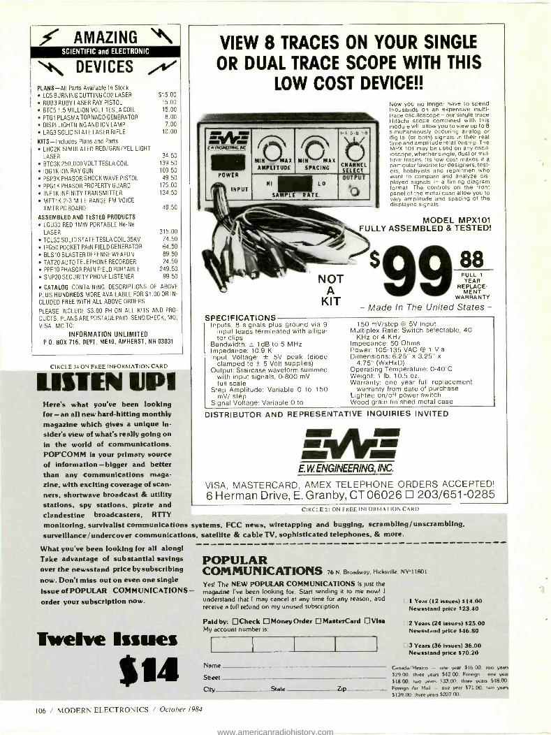
AMAZING NI\ SCIENTIFIC and ELECTRONIC
DEVICES A' PLANS -All Parts Available In Stock
LC5 BURNING CUTTING CO2 LASER
RUB3 RUBY LASER RAY PISTOL
BTC5 1.5 MILLION VOLT TESLA COIL
PTG1 PLASMA TORNADO GENERATOR
DISPI LIGHTNING AND ION LAMP
LRG3 SOLID STATE LASER RIFLE
KITS -Includes Plans and Parts
LHC2K SIMULATED RED /GRN /YEL LIGHT
LASER
BTC3K 250,000 VOLT TESLA COIL
IOG1K ION RAY GUN
PSP3K PHASOR SHOCK WAVE PISTOL
PPG1 K PHASOR PROPERTY GUARD
INF1 K INFINITY TRANSMITTER
MFT1K 2 -3 MILE RANGE FM VOICE
XMTR PC BOARD
$15.00 15.00 15.00 8.00 7.00
10.00
34.50 139.50 109.50 49.50
175.00 134.50
49.50
ASSEMBLED AND TESTED PRODUCTS
LGU30 RED 1MW PORTABLE He -Ne
LASER 315.00
TCL30 SOLID STATE TESLA COIL 35KV 74.50
IPG50 POCKET PAIN FIELD GENERATOR 64.50
BLS10 BLASTER DEFENSE WEAPON 89.50 TAT20 AUTO TELEPHONE RECORDER 24.50
PPF10 PHASOR PAIN FIELD PORTABLE 249.50
SNP20 SECURITY PHONE LISTENER 99.50
CATALOG CONTAINING DESCRIPTIONS OF ABOVE
PLUS HUNDREDS MORE AVAILABLE FOR $1.00 OR IN-
CLUDED FREE WITH ALL ABOVE ORDERS.
PLEASE INCLUDE $3.00 PH ON ALL KITS AND PRO-
DUCTS. PLANS ARE POSTAGE PAID. SEND CHECK, MO,
VISA, MC TO:
INFORMATION UNLIMITED P.O. BOX 716, DEPT. ME10, AMHERST, NH 03031
CIRCLE 34 ON FREE INFORMATION CARD
LIUE4 uni Here's what you've been looking for -an all new hard -hitting monthly magazine which gives a unique in- sider's view of what's really going on in the world of communications. POP'COMM is your primary source of information - bigger and better than any communications maga- zine, with exciting coverage of scan- ners, shortwave broadcast & utility stations, spy stations, pirate and clandestine broadcasters, RTTY
monitoring, survivalist communications systems, FCC news, wiretapping and bugging, scrambling /unscrambling, surveillance /undercover communications, satellite & cable TV, sophisticated telephones, & more.
VIEW 8 TRACES ON YOUR SINGLE
OR DUAL TRACE SCOPE WITH THIS
LOW COST DEVICE!!
WI II, MI EwerGlEHiNC.uC
POWER
INPUT
MIN M AX
AMPLITUDE MIN MAX
SPACING
1 -4 5 -8 1-8
CNANNEL SELECT
NI L0
S E
OUTPUT
w4
Now you no longer have to spend thousands on an expensive multi - trace oscilloscope - our single trace Hitachi scope combined with this module will allow you to view up to 8 simultaneously occuring analog or digital (or both) signals in their real time and amplitude relationship. The MPX 101 may be used on any oscil- loscope, whether single, dual or mul- tiple traces. Its low cost makes it a particular favorite for designers, test- ers, hobbyists and repairmen who want to compare and analyze dis- played signals in a timing diagram format. The controls on the front panel of the metal case allow you to vary amplitude and spacing of the displayed signals.
MODEL MPX101 FULLY ASSEMBLED & TESTED!
NOT A
KIT
SPECIFICATIONS Inputs: 8 signals plus ground via 9
input leads terminated with alliga- tor clips
Bandwidth: ± 1dB to 5 MHz Impedance: 10.9 K Input Voltage: ± 5V peak (diode
clamped to ± 5 Volt supplies) Output: Staircase waveform summed
with input signals, 0 -800 mV full scale
Step Amplitude: Variable 0 to 150 mV/ step
Signal Voltage: Variable 0 to
88 FULL 1
YEAR REPLACE-
MENT WARRANTY
- Made In The United States-
150 mV /step W 5V Input Multiplex Rate: Switch selectable, 40
KHz or 4 KHz Impedance: 50 Ohms Power: 105-135 VAC @ 1 V a Dimensions: 6.25" x 3.25" x
4.75 "(WxHXD) Operating Temperature: 0 -40'C Weight: 1 lb. 10.5 oz. Warranty: one year full replacement
warranty from date of purchase Lighted on /off power switch Wood grain finished metal case
DISTRIBUTOR AND REPRESENTATIVE INQUIRIES INVITED
E.W. ENGINEERING, INC.
VISA, MASTERCARD, AMEX TELEPHONE ORDERS ACCEPTED! 6 Herman Drive, E. Granby, CT 06026 203/651 -0285
C IRCI. L 21 ()N FREI- INFORMA LION CARD
What you've been looking for all along! Take advantage of sub stantial savings over the newsstand price by subscribing now. Don't miss out on even one single issue of POPULAR COMMUNICATIONS - order your subscription now.
Twelve Issues
106 MODERN LI_FCTRONICS October 1984
POPULAR COMMUNICATIONS 76 N Broadway. Hicksville, NY11801
Yes! The NEW POPULAR COMMUNICATIONS is just the magazine I've been looking for Start sending it to me now! I
understand that I may cancel at any time for any reason, aiad
receive a full refund on my unused subscription.
Paid by: OCheck D Money Order D MasterCard O Visa My account number is:
Name
Street
1 Year (12 issues) $14.00 Newsstand price $23.40
2 Years (24 issues) $25.00 Newsstand price $46.80
3 Years (36 Issues) 36.00 Newsstand price $70.20
Canada/Mexico - one year $16 00. two years
$29.00. three years $42.00. Forego - one year
sly. CO, two years $33.00. three years $48.00.
City State Zip Foreign Air Mail - one year $71 00. two years
$139.00. three years $207 00
www.americanradiohistory.com
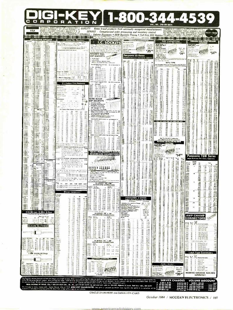
DIGI-KEY C O R P O R A T I O N
VISA
1-800-344-4539 AK., HI 218-681-66)4
NATIONAL SEMICONDUCTOR PANASONIC.; QUALITY - Name brand products from nationally recognized manufacturers. CHEMICALS ARIES PLESSEY MOLEX F. AAVID CHEMVVIK ATLANTIC DIODESI N. MACHINE DIAMOND TOOL. UNGAR GC CH ARIES PLES$EY IGOLEX AAVID E.-E. J1 SERVICE - Computerized order processing and inventory control AS HIKE DIAM D-TO AP PRODUCTS T CH OK MACHINE UNGAR GC CHEMICALS A. 2ND E&A
INSTRUMENTS GC CHEMICALS ARIES plot -K[r _ p
NATIONAL SEMICONDUCTOR PANASONIC SAVINGS - Volume Discounts OEM Quantity Pricing Toll Free BOO Number cHEMICALS ARIES PLESSEV MOLEX E. C2.2 -0101 K[ Y- 0101 -Nfr- 102_x!2 -0.12.- 0101.K[Y -pIp K[ pIGIxY - Or prOr Ker IO DI -K!Y - plGl KIY POI K27- 0101- K[Y -01 r K --. - .pr.7- pGI172Y- 17.4ír- .0101 -K_!Y
PTMASOÑIC RESIN INEETISTAWIKLUN CAPACITORS
0201 KEY -0 G1KEY - 0101 KEY - 0I01K.Y - 010, -Kfn - 0f01KEY - 0101 -FI - 011[x[ INTEGRATED CIRCUITS
U
LE
Mr
w N
,630146
WyN .73
513177
ia
m 33 ;33 P 12 2 52
54P 15 62
31..L36 6 62
4 14
3316 5 27
0297.
4.4.00
165246
I yr Oh c 1)11:1_Al: ) /Iixr r,"rrl r"rrAr. rr Big rin Nson IIMM7.1. . r{!f0lR. i1A1311 IN CAPACITORS
1 Metal Film R. .. 4000 CMOS
- . B Vohs. ys00oo 1 36
5 40 AAAAAA R00187014 yALUE 0100-13
71
as
40129
äi30
169146 2 42 ñ
®
ma6
5.7.15C7 03 007.06462 46
v¢ wu 7611160 .16
iñmi62CCT 94
LM791MC2 93 041731.164C2 60
M;99o20'oN
467807 90
411299 I 70 .04 .63 40340 FR
0400 1
MIA .20 .30 40448 a3
,...,,
,. ..
orn,.,
Is w.
404. .06 50 mw
s . u
.
Mk.. 4
ímon
ss `fó: -_
1.1s - - -WOK L.10KC 15 1.92
L.30,75 09 Call4705 .5 is trpS.
m
m 23w
-II ñ bw re93 -2 254 601006 6. 48
3tl -270K
-3yAl
LM N
1.123326 1 56 'n"w. 6.006 06.636 x.nndRT sa .. 5 4ach EA 73
L64390493 1 =""ma 42.0
;
B61W . kuwlse 50 .
:1:m 65C0306.1
1 1 I].I 6µy7.-
SM4Rr1orT 1 oSlamN S250 npl? Ivae:M esíiw .N 6M t
mom fro a mw g 3m
LC . Remember .au 1 e. lnna o. 106rv
A, M1411146-3,2.63 rorvpar.wreA3.WIVU.w.la0rvn300 ' 1 Iw2M.0DIV13.m;la for 416.00 rt. M Peei9 eNOw. rM MsQ74_ .....ae...,..r,.rw .........,_. LMMICE2 54
I>«n ,r.I,
H
L
H d
413= Z
LM14686 67 014014
LM11112N 10 29
17171.. 5 03 .11370 2 04
21621116 1 54
Leman+ as 11633206 0623046 77 1ao3613366
w7". 314
E66S7x 16.0665
.m
W163146 7.0 MAMMA. 3.00
70610N . 20
22r. 12
A)DE D)A
600410311617 32 40.6044044 53
6660312.1160 0.80.66.92
4 Aac®C04 5C0
7... 61DN 7484724N 5.76
74047666.
)4mlx
Pdoe /6110 151 1. 01110 MM MAI
ski ..s-oo 1,1500 w 1310 N ëwrMlOm B4M13 26N7.w
Silicon Transistors
12001633
7.335 ACC371.3 1377
Aomsl`c2DE1m 26404
°oñmmnC3ói 2
26039 4116 200 nsec. 16,38081 D Ram
41166 NO 52905 NO
,,.eEacn
PM. 6461.06 .817
SILICON RECTIFIERS - NC _L.. . II 15 1101 DAN 16001 eat .4 100 IN m
0041 ea 7:00 p e
0003 Am2mm 0041 00 7 50 3403 563 00 1.9 raw 041 16 7
114005 .600 PN 0641 1 00 00 14 00 636 00 ems 6,NM 041 1 00 053 110 0 661 00 woe .lam 994 NIM
OW 0041 60 SW 3200 21660 Dn.
3pAMP SILICON RECTIFIER
Pure
OoMIO. Pis. I 16 10 IS MAWá
á.N2v I Pra°e a II90 199
NNW Nsa3 Amp 20anv Pmu
240 2 Nsm4 3 Amp 400Prv Ptnt :.D 1: 2310 66a é Ano tla19V Pun
5 2Rm 245.00
73Anp6001952 PNnu .40 30 N6tpe 60 2.000 m
6763.
1 10 140
GO 106 00 N 2 70 18 90 23 2 70 1690
23 770 1090
24 7 72 20 On
67 5 70 54 CO
78 7 75 63 0 711 7 35 63E0
73 7 70 19 30 73 73 2 76 .93 173 73 10 90 173
160 03 28 2 62 27 50 206 26
73 7 20 18 90 03 25 73 2N 16 90 03 26
747 9/
A IN TRUMENT I.C. SOCKETS
AMv eon..
npn v
SOLDER TAIL DIP SOCKETS -ee.
TIN PLATED 80100 TAIE smw wrw R4908 6 pin tionler MI. tin .13 5 1099 .14 r rarn odes tad un 15 1.45 11.00 .6 16 orn adder tarl. on 17 60 13.00
48920 20pn solder 1.1. tin 23 2.10 20 00
C8940 40 pm 0198 61.. 40 410 a.m M LAY BNUR TAR W. ee...eee
.11434173463rT OF 16 90.564
Cat. N. P8200-Kh
ONLY
63595
Panasonic LS Series Miniature Aluminum EMmrolyKc Capacitors
2.261
rAF Ç i
A.0 149
Di6i .)4 i1. .14 1.16 1.'2A1
4 11200 /6.3 000 /61
0300 6ó 1:
P. M. I Is m 011336 pa. .w.. 320 3100 C3814 14 rm 62044 W. 0.1 .44 m.3 09318 18 pin soklor
7TA r. wx 93.w2d.
470 43N
w,wx. 5N 67.W 300
csen a pxd IaaO°Wp
Na. gold OMB 28 pin solder yrr. gala 79 7 50 730 ä
gold 1 12 9 90 97.00
WIRE WRAP
prom DIP SOCKETS - ,
Yolverael mom.. er. Cam. mcommoM4
ewm`iw : °PMwOp.r ä ® e..wa m. M a`oeó
TM PLATED 61116 wRAP an
áIw 1 18 IN
ne Iew.vn w. 4 60 6W
0024 24 pin mre wm. 11 8.90 0 03
ñ1ñ nn wo" 0.00 134001.07 WRAP eea.e
114.
mP. ewe 03114 p 9. um 16 cm .vxd
01120 20 pin ,o4 :á: go. 19 11 93 117.03 C3112 .1. woe wrap. 6010
1 29 12.00 127.00 W124 pn win won gold 1.79 13.01 177.0 .128 28 T9!b wPn.,r.ro:á :. .
TEXASINSTRUMEN LD EDGESOARD CONNECTORS
Au, 40 J1JJ ...__ 1313=,µiN,
Ne tEÑTES .LOP x.200. EDOEBOARD CONNECTORS
C616 4.50 43 43 C515 3_40 31 50
16/36 C6 18 4.80 0.40 C518 4 33.90 20/ 40 C6-20 5.30 4930 C520 3.90 37 40
C673 5.60 63.0 C6.22 4 33 400
06-213 5.30 61 40 C520 66 0.03 C633 6.40 62 60 C530 4.96 48.
CO 76 7.50 73.80 C630 5 70 56.50 C6. 9.60 131 10
CO 43 3.33 93 20 6.30 61 70
Ce. 10 60 00 C649 7 80 76.93
IN SERIES .125" .2811- EDOEBOARD CONNECTORS
C4-10 4 36 023 C3-10 2.95 2130 C415 5.33 49 60 C315 3.40 33 40
3.95 36 70 94
m G II 510 93.10 03.3
6479 6 70 .30 C3.28 4.56 47 40
04.31 7 30 70 60 63.11 5.25 51 70
eY^, IN SERIES .1511- .200"ns , EDOEBOARDCONNECTORS
11230 CI 10 2.55
624 Cl 16
10 a.t1 99a .
1324 C1 12 2 0 77.50 1
I8/36 ¢le 6.07 4362
2
. ..
p..
. . _. . .,.
r
a m
$14.95
370 470 IOW
330ßw0
4700
2i 7a
IB1 .n 1.
199
/595 17 63
1003
4700 2
233 333 /35
1 83
w 6
m0 r n. 00 4700 /36
17
83 14.17 118 03
4.
103
ID 1000 2a
0.47
10
445
DISC CAPACITORS
NEW,tKIT y 'I 310 DISC CAPACITORS ..
qev m. in Pai b er,vq
titi. won 63304171117 11
.618600 01101.
CAT. NO OH KIT MlY
B24ee 'S-451350
. 1:
MN ...:- 2951 14614 new
.0E400...3.3 Cv e.pamm iw ®nt of Penamt
oOm
NPO TYPE FwOw............/2919014137 epaewPl.plwlSbaMl1.v1ox
E'rkp_
M No w aP N W 1^ 64003 . of 500 6.40 N.)I
Ná1 é D 401 PI 01
4een P4.5 n q 60
Pa 33 q N.)1 5407
64008 pf 602
N N.71
B82
..71 ®W
ro 9 54.
P4011 p 6 723 6U 72
w100 60q wR 4 q m0 6.43 40.73
ffiñ 933 6.43 0.72
70 pf
mq s:á 43.72
BM pf ®
p á m0vf 1500 Pf 60 84.35 1800 pi SW 1 31 11 23 0 37 ®q 1D3 0 501 37.57
144.702 Smq 100 .0 a00g 0i POW 3303 of ICO 59 e01 37.5
243343 000 q ion 56 501 57 éáó 03
P4707 .7 uf 25 u 25 I 79 1537 11631
P4431 10 pf 500 n 6 28 47 13 64402
is á 600 81 6 97
IIq 33 600 703 6 80 05 71
1.407 30 61 606 6461 47 9 500 12.7 17 BO 88 53
1.410 má n 6W 2.4 17.50 u1. 96
I..rDaTME Pnm op ̀w axepNw. PANASONIC METALLIZED POLYESTER
CA PACITORI
NEW KIT
'W" PA 01 0 Ps III
En. M
II
]
53 2.12
140 rs
103 IS .17
21224 : 170 56 2.N 16 2U
á
ß II .n 190 63
M
b DIN .N 3.44 28 85 257.6
47 40 33.46 301 Im Itl b n 1
s W . 0 i tN
41 PO 13 30 s E 48.50 . 3340:12 )0 _ - .. 1 1.01 8M 71.99 647.M
4 33
16tB i64 i I !.Á i.
.120.73
m , 187.0 75643 10
31. 1075
21103 250 19 1 64 13.00 123.09
3m.T2 - F21tl 250
63333 260 033 19 1 04 13.0 173 0 62331 .0 037 .19 1 64 13.66 123.08 .73 1.63 250 066 .22 1.6 160
4v 30.00
.:0N
ÁN
275.6 4.02 33.0
Ñá non
3204 250
á65 767.06
2 :13 2:13 ME 7 89 67.40
0 0018 11 91 m
0 0023
:
.
ltá S 9M T aÑÓ 0 0016 11
A.4 6891 Ha 15
0 0038 .11 91 7.0 57 40 F4223 400 Or
0.0056 11 91 7 0 57 40 64333 400 .03
64823'' `
0 03 SS 90 II 96 8 47 51 GO mq
9.15 66.83 01184 . 10 m
4.66 36.96 360.78
0 033 13 1 19 10 23 74 40 Ú D w1 64.N
16 I 42 1120 99.20 64004 . 66
U 0 18 N 2 31 19.00 139.20
/52_186 7376.55
0 22 27 2 42 20.63 151 SO
0 27 30 2.70 23 n 169 00
0 33 13 3 00 25.73 107 00
46 4.21 76 N 103.80
6 32 0.78 333 CO
PANASONIC V- SERIES
.603
.504
64507 6406
144.0
6.12 64613 64514
64610 .517 24516 6019
645. 6.23
2.6 0.33 0.30 6409
.533
404C to áÉ
00ú506956 é.Pe
men.. Met film
IN w.103416 pa 44
60.41.807 OF
CAT. NO. 3050P-RI
ONLY
63595
354g5
- 1 B.! 3.16 .31 fr. tit ñ°s:m
0.36 Paos a 3.16
PI,01007V9
3:16 IL )5 26 60a.ä
.6 2i tlS 19RB INB.S
}
'i2i ro
2
í453 i
1
ñ26m
N
tl 6
R E ñi6s1T
60 7.@áx:.:
ó
i411
Pt
á
Pam 3.3
1
Á160 em:
116.81
ñ 731.51 06.75
ii
26193
4311
PiPam
®ÿ
152031 P6332 I
Pam 1.6
Pús 11
Pmn
6200 .16 I
IMI Y
a 4421142
0204 22046
PmD
9 SA
r0.m
220.60 267.00
10 00 MO 00 62.63 1462 50
187 60 1777.50
em
11 E 0 60 202 50
á 1'1 E
:m 720 SO
14 a 752 W
620413 6 .2.50 0200 10 26 53)75
75 1155 7: 50 NM 60 . 1916 50 2050
2m.60
RE 0.15 36
71057 0.47 35 P2059 0.08 36 PEW 1 0 36 00013 1 6 36
2.2 15 .
é r]4 s 64100 3 mm
P2°s 3 15 50 2.79 72.60 202.60
14509 s 0.72 50 1 170 22.60 2020 62070 0 33 50 .31 2 70 72.50 621371 0,47 50 3) 3.30 28.32 254
62077 1.0 50 .64 4.66 38.75 >; ° 61074 1.5 50 .63 540 46.00 40.00
62076 2.2 60 .74 0.36 63 00 :® ]6 P0 A 1.01 N 1. 172.M 60 1327.á
Panasonic TSW Series terge *15017um (1e01001000 Capaortors
0600
6002 60603 PR01
65135
6166 PamB 4060 6610
61612
N617
01316
66617 166111
NAM
1.521
Pam .50 e431
xx spa y on.
WI I 1 IN 3350 11.20 15N 4 MOO 400 1.46 11.17 101.00 Nm 131 14.73 132E0 Iam 00
S 2200 1.27 9.tl 4W a00 4.W
WO 20 1913 173.00 IOöO 722 .16 700 16000 4.14 7161 76.00
003 1.50 7. 7203
1ñm 4700 230 11541 14W ;
Y 0
33.01 Aro I0000 36.511
60 1101 1.15 0. 4m ON W 3y 1N.W 4a 3N 25.61
4.b1 M. 701 00
IW 470 1.41 11.14 14W 100.69
m0 mm 723 181 II.b 40
m 40
AMP CHAMP CONNECTORS
26.111 233.00
18.0 1711.130
20.00 1000 23. 3310 300 I0.OL
Min aeP
e M alertioe.erre N Cable Saew Lo, 36 Cable 09. Look
A15. 36 Cable .1Le.
41508 . 6607 6508 61609 30
Caine Sow L. CNN Scant 1.4. Cade Soarn 0619 Ca. Smin .61
41579 !Mande W. Insertion Too1
2.21 P1515 36
w PC 6 PC ros p e PC p 9.1 Arp. PC N. 1961 Anie
3 57
fi
Latch Type Connectors
MBn sA
Fib 4N..w1 oe,.r
41362 36 P Screw 9
41563 36 P 6441.1 9 27
9 62
MOUNTING HARDWARE AVAILABLE SEPARATELY.
The DigeKey volume discount and service charges are simple to apply. MOST items sold by Dei-Key may be combined for a volsne discount. Items ihot ore not discountable are identified by the SERVICE CHARGES VOLUME DISCOUNT suffix -ND following the pan number. After writing your order, total all of the discountable items and apply the appropriate discount. To this subtotal, add the non -discountable items. Then add Ae service charge. We pay all shipping and insurance to addresses in the U.S.A.. Canada on Mexico when shed or money order aceompoAes order. f 0.00 4 9.99.... Add 52.00 5 0.00 -5 99.99 NET Max OWNING IT PMes[, CALL 1000 -1 {{- {379 (M., Ak., RI., ate 218.6314574) By moll 00M 5 10.00.525.00 Add $0.50 S 100.00. 5249.99.... Less 10.0 your mho" tot DIGI -MT, Nigkry 32 South, Thief Rimy Fall, MR 56701 t 23.00 -549.99 Add 20.50 5 250.00.5499.99. Less 33.0 You may pay by check. money order. Master Charge, VISA or C.O.D. DIGS -KEY GUARANTEE: Ally pans or products purchased from Digi.Key Mot 0rp0e .c be 30100ä0e will be f 50.00.599.99 Add 50.23 S 500.00 -5999.99 ...less 20. placed or refunded if returned within 90 days from receipt with a copy of your invoice. S100.00 8 Up No Change $1000.00 6 Up Less 251.
CIRCLE 23 ON FREE INFORMATION CARD
October 1984 / MODERN ELECTRONICS / 107
www.americanradiohistory.com

DON'T LET THE ELECTRONICS REVOLUTION PASS YOU BY
BECOME A CHARTER SUBSCRIBER TO
Now you can reach out every month and learn about the latest innovations in consumer electronics and personal computers -what's new, how products and circuits work, and what leading authorities think of them.
*Stereo *Video *Home & Car Electronics *Test Instruments *Circuitry & Devices *Servicing
*Personal Computers *Communications *Construction Projects In every issue, authors lucidly explain how exciting, new electronics ideas are
applied ... issue forthright buying counsel ... present complete plans to build electronic devices to enhance products, even unique ones that are not yet being sold in the marketplace.
Feature articles, tutorials, and construction projects are the hallmarks of MODERN ELECTRONICS, the new monthly magazine for electronics and computer enthusiasts. Covering the entire spectrum of these fields, you'll gather insights in every important area to help you make buying decisions for work and play purposes ... improve performance of your present equipment ... increase your electronics competence ... and add to your practical and intellectual knowledge of electronics and computers.
To be sure you get this valuable information delivered to you regularly, and share the experiences of our writers and editors -Forrest Mims, Len Feldman, Stan Prentis, Charles Rubenstein, Glenn Hauser, and many others -you can subscribe to MODERN ELECTRONICS today. As a Charter Subscriber, you'll save 45% off the newsstand price when you buy a one -year subscription for only $12.97. Or save 51% when you subscribe for two years at $22.97.
Acting now you won't miss any of our exciting upcoming features, such as the "Circuit Designing From Scratch" series starting in November that will show you, step by step, how to create your own circuits to perform tasks you dream up; "Solving the Extension Speaker Impedance Matching Puzzle," "Delayed- Action Auto Theft Deterrent" Project, and more.
Just fill out the coupon and mail with your check, money order, or credit card information (Visa or MasterCard) to enter your Charter Subscription. Do it today to ensure earliest delivery!
MODERN ELECTRONICS 76 North Broadway, Hicksville, NY 11801
Please send me Modern Electronics for 2 Years 1 Year
Name
Street
City
State Zip
Charge My Order To: Payment Enclosed $ 2 Years (24 issues) $22.97
MasterCard
VISA
My account number is: 1 Year (12 issues) $12.97 IIIIIIIII IIIII 108 / MODERN ELECTRONICS / October 1984
ADVERTISERS' INDEX
AMC Sales, Inc 104
AP Products Coy. IV
Advance Electronics 42,43 All Electronics Corp 105
Cleveland Institute of Electronics 41
Communications Electronics .. 53, 62, 63, 95 Contemporary Electronics Series 27
Digi -Key Corp. 107
Electronic Specialists 94 Electronics Book Club 67
E.W. Engineering, Inc. 97, 106
Global Specialties 2
Grantham College of Engineering 1
Haltronix, Inc 88
Handy Products 79
Heath Co 17
Information Unlimited 106
Memotech Corp. Cov. III NRI Schools 82,85 Paia 88
RCA Distributor 5
Radio Shack 61
Random Access 94
Sintec Co 99
Uniden Bearcat Cov. II Wahl Clipper Corp. 89
Wersi Electronics 104
Free Product Information Readers can obtain free information on products advertised by the above com- panies, as well as for some editorially mentioned products. Simply circle the appropriate number printed below an advertisement onto the Modern Elec- tronics "Free Information Service" card bound into this issue. After filling in your name and address, just mail the postpaid card. Your request will be for- warded directly to the advertiser with a mailing label prepared by our reader - service department to ensure speedy re- sponse.
www.americanradiohistory.com

A WORLD APART FROM THE ORDINARY Introducing the MTX512
Step into a new realm of microcom- puter technology.
Where computers are housed in sleek black metal cases. Computer languages work in interactive harmony. And com- puter owners finally move up to a system they won't outgrow.
Step into the extraordinary world of the MTX512.
Interactive Software: An MTX Exclusive
This is the way all micros should perform. Interactively.
With the MTX, you can create and manipulate programs using four different languages in dynamic interaction, all coordinated through the FRONT PANEL DISPLAY. And the languages housed in the MTX's 24K ROM will satisfy the needs - and desires - of both novice and highly advanced pro- grammers. In addition to powerful MTX BASIC and MTX GRAPHICS languages, you get NODDY, an 11- command "easy learn" language, and MTX ASSEMBLER, which enables sophisticated programming in assembly language.
Serious programmers will also appreciate our ASSEMBLER/ DISASSEMBLER, tied to BASIC, which gives them unprecedented display and keyboard access to Z80 CPU storage locations, memory and program.
64K to 512K USER RAM, And So Much More
Never has so much performance been designed into a single microcomputer. With 64K user RAM, and expansion capabilities that can take you up to 512K, the MTX is the perfect micro for a wide range of applications.
Graphics capabilities? The MTX starts off where other micros usually end up. Delivering 16- color, 256 x 192 high resolution graphics. In a format powered by 32 easily movable, user -defined sprites.
The MTX also gives you eight definable windows, to operate in- dependently or in tandem. And still maintain full screen capabilities. We call them Virtual Screens. You'll call them extraordinary.
Far from ordinary as well are the built - in systems outputs that come standard on the MTX. The Centronics parallel printer port. The two industry- standard joystick ports. The uncommitted parallel I/O port. The 2400 baud Cassette port. Separate TV and Video Monitor ports. The 4- channel sound hifi output. We've even installed a ROM cartridge port for Word Processing and other dedicated programs.
Word Processing for $999 This is word processing the way it
should be. Quick. Easy. Professional. For a limited time, you can purchase a package that includes the MTX512S; the powerful NewWord, word processing ROM board; and the Memotech DMX80 correspondence quality printer *. An exceptional value!
A Computer That Grows Into a System
The MTX was designed to grow, and to keep on growing. With a full line of Memotech system peripherals that will answer your growing needs. The MTX's Z80A processor, running at 4MHz, enables you to expand into the MTX hard disc, MTX Silicon and Floppy Disc CP /M operated systems. Systems that could provide up to 160 megabyte storage capacity. That's power you might one day need; considering that the MTX can be used in an interactive com- munications network (OXFORD RING° ) linking up to 255 units.
Now, The Bottom Line The more engineering you put into
designing a computer, the less it will cost to produce. Which is why we can sell it for $299* *.
And why we can confidently back it up with a full one -year warranty.
See the MTX512 at your computer dealer now or contact Memotech Corporation, 99 Cabot Street, Needham, MA 02194; or phone (617) 449 -6614.
Toll Free Number 1 -800- 247 -5570
MEMOTECH CORPORATION
CIRCLE 51 ON FREE INFORMATION CARD
NewWord TM is a trademark of NewStar Software Inc. CP /M is a trademark of Digital Research. Inc. *DMX80 suggested retail price $395. "Suggested retail price.
DEALER INQUIRIES INVITED
www.americanradiohistory.com
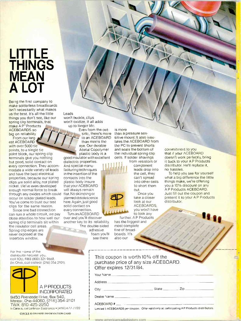
LITTLE THINGS MEAN A LOT Being the first company to make solderless breadboards isn't necessarily what makes us the best. It's all the little things you don't see, like our spring clip terminals, that make A P` Products ACEBOARDS so big on reliability.
From our larg- est ACEBOARD with over 5000 tie points, to a single tie point block, our spring clip terminals give you nothing but good, solid contact on every connection. They accom- modate a wide variety of leads and have the best electrical properties, because our spring clips are solid alloy, not plated nickel. We've even developed enough normal force to break through any oxides which could occur on solder plated leads. You've come to trust our test clips for the same reason.
Since one bad connection can ruin a whole circuit, we pay close attention to how well our spring clip terminals sit within the insulator cell areas. Spring clip edges are never exposed at the insertion window.
Leads won't buckle, clips won't oxidize, it all adds
up to longer life. Even from the out-
side, there's more to an ACEBOARD than meets the
eye. Our durable Acetal Copolymer plastic body is a
good insulator with excellent dielectric properties. And special manu- facturingtechniques in the insertion of the contacts into the plastic body insure that your ACEBOARD will always remain flat. No skimping or planned obsolescence here.Again, just good solid contact on every connection.
Turn an ACEBOARD over and you'll discover another key to its reliability.
The double -sided adhesive
foam you'll see there
For the name of the distributor nearest you, call TOLL FREE (800) 321 -9668. (In Ohio, call collect: (216) 354 -2101).
is more than a pressure sen- sitive mount.lt also insu- lates the ACEBOARD from the PC to prevent shorts and seals the bottom of the individual spring clip cells. If solder shavings
from resistors or component leads drop into the cell, they can't spread into other cells to short them out.
Once you take a closer look at our ACEBOARDS, you won't have to look any
further. A P Products has the biggest and most complete line of bread- boards. It's also our
A P PRODUCTS INCORPORATED
9450 Pineneedle Drive, Box 540, Mentor, Ohio 44060, [216] 354 -2101 TWX: 810 -425 -2250 In Canada, call Lenbrook Electronics (416) 477 -7722
CIRCLE 83 ON FREE INFORMATION CARD
r
commitment to you that if your ACEBOARD doesn't work perfectly, bring it back to your A P Products distributor. He'll replace it, no hassles.
To help you see for yourself what a big difference the little things make, we're offering you a 10% discount on any A P Products ACEBOARD. Just fill out the coupon and present it to your A P Products distributor.
This coupon is worth 10% off the purchase price of any size ACEBOARD. Offer expires 12/31/84.
Your Name
Address
City State Zip
Dealer Name
ACEBOARD #
Limited 5 ACEBOARDS per coupon. Offer valid only at participating A P Products distributors.
www.americanradiohistory.com