first order transient circuits in circuits with inductors and capacitors voltages and currents...
TRANSCRIPT

FIRST ORDER TRANSIENT CIRCUITS
IN CIRCUITS WITH INDUCTORS AND CAPACITORS VOLTAGES AND CURRENTSCANNOT CHANGE INSTANTANEOUSLY. EVEN THE APPLICATION, OR REMOVAL, OF CONSTANT SOURCES CREATES ATRANSIENT BEHAVIOR
FIRST ORDER CIRCUITSCircuits that contain a single energy storing elements.Either a capacitor or an inductor

THE CONVENTIONAL ANALYSIS USING MATHEMATICAL MODELS REQUIRES THE DETERMINATION OF (A SET OF) EQUATIONS THAT REPRESENT THE CIRCUIT.ONCE THE MODEL IS OBTAINED ANALYSIS REQUIRES THE SOLUTION OF THE EQUATIONS FOR THE CASES REQUIRED.
FOR EXAMPLE IN NODE OR LOOP ANALYSIS OF RESISTIVE CIRCUITS ONE REPRESENTS THECIRCUIT BY A SET OF ALGEBRAIC EQUATIONS
WHEN THERE ARE INDUCTORS OR CAPACITORS THE MODELS BECOME LINEAR ORDINARY DIFFERENTIAL EQUATIONS (ODEs). HENCE, IN GENERAL, ONE NEEDS ALL THOSE TOOLS IN ORDER TO BE ABLE TO ANALYZE CIRCUITS WITH ENERGY STORING ELEMENTS.
ANALYSIS OF LINEAR CIRCUITS WITH INDUCTORS AND/OR CAPACITORS
THE GENERAL APPROACH CAN BE SIMPLIFIED IN SOME SPECIAL CASES WHEN THE FORMOF THE SOLUTION CAN BE KNOWN BEFOREHAND. THE ANALYSIS IN THESE CASES BECOMES A SIMPLE MATTER OF DETERMINING SOMEPARAMETERS.TWO SUCH CASES WILL BE DISCUSSED IN DETAIL FOR THE CASE OF CONSTANT SOURCES. ONE THAT ASSUMES THE AVAILABILITY OF THE DIFFERENTIAL EQUATION AND A SECOND THAT IS ENTIRELY BASED ON ELEMENTARY CIRCUIT ANALYSIS… BUT IT IS NORMALLY LONGER
A METHOD BASED ON THEVENIN WILL BE DEVELOPED TO DERIVE MATHEMATICAL MODELSFOR ANY ARBITRARY LINEAR CIRCUIT WITH ONE ENERGY STORING ELEMENT.
WE WILL ALSO DISCUSS THE PERFORMANCE OF LINEAR CIRCUITS TO OTHER SIMPLE INPUTS
THE MODEL

AN INTRODUCTIONINDUCTORS AND CAPACITORS CAN STORE ENERGY. UNDER SUITABLE CONDITIONS THIS ENERGYCAN BE RELEASED. THE RATE AT WHICH IT IS RELEASED WILL DEPEND ON THE PARAMETERSOF THE CIRCUIT CONNECTED TO THE TERMINALS OF THE ENERGY STORING ELEMENT
With the switch on the left the capacitor receivescharge from the battery.
Switch to the rightand the capacitordischarges throughthe lamp

dxxfetxetxet
tTH
xtt
)(1
)()(0
0
0
GENERAL RESPONSE: FIRST ORDER CIRCUITS
0)0(; xxfxdt
dxTH
Including the initial conditionsthe model for the capacitorvoltage or the inductor current will be shown to be of the form
Solving the differential equationusing integrating factors, one tries to convert the LHS into anexact derivative
t
TH efxdt
dx 1/*
TH
ttt
fexedt
dxe
11
TH
tt
fexedt
d
1
t
t0
dxxfetxetxt
t
TH
xttt
)(1
)()(0
0
0
0)0();()()( xxtftaxt
dt
dx
THIS EXPRESSION ALLOWS THE COMPUTATIONOF THE RESPONSE FOR ANY FORCING FUNCTION.WE WILL CONCENTRATE IN THE SPECIAL CASEWHEN THE RIGHT HAND SIDE IS CONSTANT
t
e
/*
circuit
the of speed reaction the on ninformatio
tsignifican provide to shown be willit
constant." time" the called is
.switchings sequentialstudy
to used be can expression general
The arbitrary. is , time, initial The ot

FIRST ORDER CIRCUITS WITHCONSTANT SOURCES
dxxfetxetxt
tTH
xttt
)(1
)()(0
0
0
0)0(; xxfxdt
dxTH
If the RHS is constant
dxef
txetxt
t
xtTH
tt
0
0
)()( 0
xtxt
eee
dxeef
txetxt
t
xtTH
tt
0
0
)()( 0
t
t
xtTH
tt
eef
txetx0
0
)()( 0
00
)()( 0
ttt
TH
tt
eeeftxetx
0
)()( 0
tt
THTH eftxftx
0tt The form of the solution is
021 ;)(0
tteKKtxtt
Any variable in the circuit is ofthe form
021 ;)(0
tteKKtytt
Only the values of the constants K_1, K_2 will change
TRANSIENT
TIMECONSTANT

EVOLUTION OF THE TRANSIENT AND INTERPRETATION OF THE TIME CONSTANT
A QUALITATIVE VIEW:THE SMALLER THE THE TIMECONSTANT THE FASTER THETRANSIENT DISAPPEARS
With less than 2% errortransient is zerobeyond this point
Drops 0.632 of initialvalue in one time constant
Tangent reaches x-axis in one time constant

CRTH
THE TIME CONSTANT
The following example illustratesthe physical meaning of timeconstant
vS
R S a
b
C
+
vc
_
Charging a capacitor
THCC
TH vvdt
dvCR
The model
0)0(, CSS vVv
Assume
The solution can be shown to be
t
SSC eVVtv
)(
CRTH
transientFor practical purposes thecapacitor is charged when thetransient is negligible
0067.0
0183.00498.0135.0
5
432
368.0
t
et
With less than 1%error the transientis negligible afterfive time constants
dt
dvC C
S
SC
R
vv
0
S
SCc
R
vv
dt
dvC
: KCL@a

1. THE CIRCUIT HAS ONLY CONSTANT INDEPENDENT SOURCES
THE DIFFERENTIAL EQUATION APPROACH
CIRCUITS WITH ONE ENERGY STORING ELEMENT
CONDITIONS
2. THE DIFFERENTIAL EQUATION FOR THE VARIABLE OF INTEREST IS SIMPLE TO OBTAIN. NORMALLY USING BASIC ANALYSIS TOOLS; e.g., KCL, KVL. . . OR THEVENIN
3. THE INITIAL CONDITION FOR THE DIFFERENTIAL EQUATION IS KNOWN, OR CAN BE OBTAINED USING STEADY STATE ANALYSIS
SOLUTION STRATEGY: USE THE DIFFERENTIAL EQUATION AND THE INITIAL CONDITIONS TO FIND THE PARAMETERS ,, 21 KK
( )
1 2
FACT: WHEN ALL INDEPENDENT SOURCES ARE CONSTANT
FOR ANY VARIABLE, ( ), IN THE CIRCUIT THE
SOLUTION IS OF THE FORM
( ) ,Ot t
O
y t
y t K K e t t

If the diff eq for y is knownin the form
Use the diff eq to find twomore equations by replacingthe form of solution into thedifferential equation
0
01
)0( yy
fyadt
dya
We can use thisinfo to find the unknowns
feKKaeK
att
2102
1
0110 a
fKfKa
0
120
1 0a
aeKa
at
t
eK
dt
dy 2
0,)( 21 teKKty
t
21)0( KKy
Use the initial condition to getone more equation
12 )0( KyK
SHORTCUT: WRITE DIFFERENTIAL EQ.IN NORMALIZED FORM WITH COEFFICIENTOF VARIABLE = 1.
00
101 a
fy
dt
dy
a
afya
dt
dya
1K
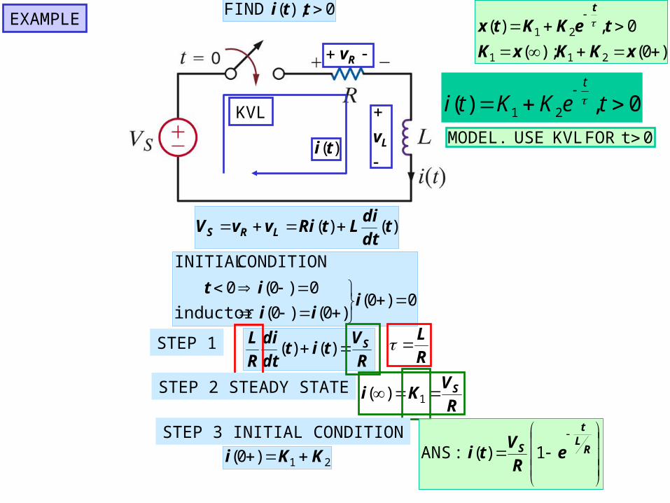
0),( tti FIND
0t FORKVL USE MODEL.
Rv
Lv)(ti
KVL
)()( tdt
diLtRivvV LRS
0)0()0()0(
0)0(0
iii
it
inductor
CONDITIONINITIAL
STEP 1R
Vtit
dt
di
R
L S )()( R
L
STEP 2 STEADY STATER
VKi S 1)(
STEP 3 INITIAL CONDITION
21)0( KKi
RLt
S eR
Vti 1)( :ANS
EXAMPLE
)0();(
0,)(
211
21
xKKxK
teKKtxt
1 2( ) , 0t
i t K K e t

0),( ttvO FIND
C
1R
2R
KCL USE 0.t FORMODEL
0)()(0)( 2121
cCCC vtdt
dvCRR
RR
vt
dt
dvC
sFCRR 6.0)10100)(106()( 6321 STEP 1
)(3
1)(
42
2)( tvtvtv CCO
STEP 2 0,)( 21 teKKtv
t
C 01 K
INITIAL CONDITIONS. CIRCUIT IN STEADY STATE t<0
)0(Cv V)12(9
6
][88)0( 221 VKKKvC STEP 3
0],[8)( 6.0
tVetvt
C
0],[3
8)( 6.0
tVetv
t
O
)(tvc DETERMINE
)0();(
0,)(
211
21
CC
t
C
vKKvK
teKKtv
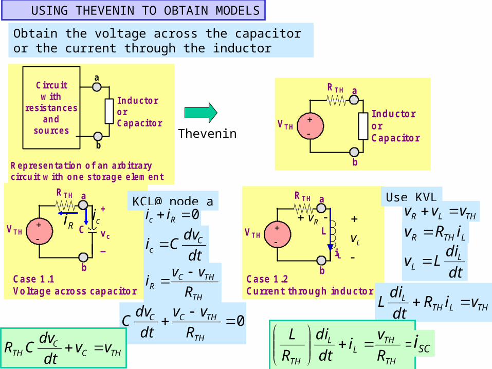
USING THEVENIN TO OBTAIN MODELS
Obtain the voltage across the capacitor or the current through the inductor
Circuitw ith
resistancesand
sources
I nductororCapacitor
a
b
R epresentation of an arbitrarycircuit w ith one storage elem ent
Thevenin VTH
R TH
I nductororCapacitor
a
b
VTH
R TH a
b
C
+
vc
_
Case 1.1Voltage across capacitor
VTH
R TH a
b
L
iL
Case 1.2Current through inductor
KCL@ node a
ciRi0 Rc ii
dt
dvCi C
c
TH
THCR R
vvi
0
TH
THCC
R
vv
dt
dvC
THCC
TH vvdt
dvCR
Use KVL
Rv
Lv
THLR vvv
LTHR iRv
dt
diLv L
L
THLTHL viRdt
diL
TH
THL
L
TH R
vi
dt
di
R
LSCi