first rf test results of two-cavities accelerating
TRANSCRIPT
FIRST RF TEST RESULTS OF TWO-CAVITIES ACCELERATING CRYOMODULE FOR ARIEL E-LINAC AT TRIUMF
Yanyun Ma†, Z. Ang, K. Fong, J. Keir, D. Kishi, D. Lang, R.E. Laxdal, R. Nagimov, Z.Y. Yao, B.S. Waraich, V. Zvyagintsev, TRIUMF, 4004 Wesbrook Mall, Vancouver B.C., V6T2A3, Canada
Abstract The Advanced Rare Isotope Laboratory (ARIEL) pro-
ject requires a 50 MeV, 10 mA continuous-wave (CW) electron linear accelerator (e-Linac) as a driver accelera-tor. Now the stage of the 30MeV portion of the e-Linac is under commissioning which includes an injector cry-omodule (ICM) and the 1st accelerator cryomodule (ACM1) with two cavities configuration. A single 290kW klystron is used to feed the two ACM1 cavities in vector sum closed-loop control. In this paper the initial commis-sioning results of the ACM1 RF system will be present.
INTRODUCTION TRIUMF is developing high intensity e-Linac driver to
produce RIBs through photo-fission [1]. A first phase of ARIEL consisting of injector cryomodule(ICM) and an accelerating cryomodule with just one accelerating cavity on board plus a `dummy’ cavity that occupies the second cavity space in the cryomodule (ACMuno) was installed for initial technical and beam tests up to 22.9 MeV in 2014 [2].
The ACMuno cryomodule was removed from the vault. The hermetic unit was updated with the 2nd cavi-ty(ARIEL4), 2nd pair of power couplers, HOM dampers, scissor tuner, RF pick-up and diagnostics. The ACM1 high-power RF distribution system and LLRF system were updated for 2 cavities configuration. Now ACM1 is under testing to meet the operational goal of 3mA at 30MeV which is shown in Fig. 1 for first science applica-tion from ARIEL ISOL targets [3,4].
Figure 1: The present configuration of the e-Linac.
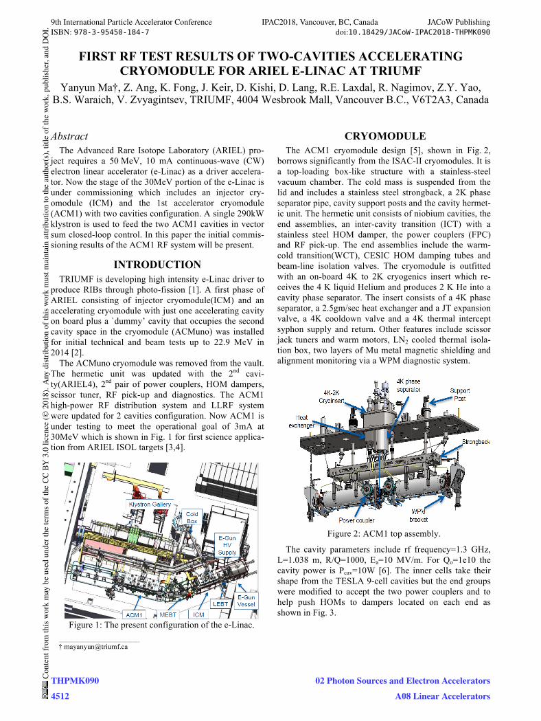
CRYOMODULE The ACM1 cryomodule design [5], shown in Fig. 2,
borrows significantly from the ISAC-II cryomodules. It is a top-loading box-like structure with a stainless-steel vacuum chamber. The cold mass is suspended from the lid and includes a stainless steel strongback, a 2K phase separator pipe, cavity support posts and the cavity hermet-ic unit. The hermetic unit consists of niobium cavities, the end assemblies, an inter-cavity transition (ICT) with a stainless steel HOM damper, the power couplers (FPC) and RF pick-up. The end assemblies include the warm-cold transition(WCT), CESIC HOM damping tubes and beam-line isolation valves. The cryomodule is outfitted with an on-board 4K to 2K cryogenics insert which re-ceives the 4 K liquid Helium and produces 2 K He into a cavity phase separator. The insert consists of a 4K phase separator, a 2.5gm/sec heat exchanger and a JT expansion valve, a 4K cooldown valve and a 4K thermal intercept syphon supply and return. Other features include scissor jack tuners and warm motors, LN2 cooled thermal isola-tion box, two layers of Mu metal magnetic shielding and alignment monitoring via a WPM diagnostic system.
Figure 2: ACM1 top assembly.
The cavity parameters include rf frequency=1.3 GHz, L=1.038 m, R/Q=1000, Ea=10 MV/m. For Qo=1e10 the cavity power is Pcav=10W [6]. The inner cells take their shape from the TESLA 9-cell cavities but the end groups were modified to accept the two power couplers and to help push HOMs to dampers located on each end as shown in Fig. 3.
____________________________________________
9th International Particle Accelerator Conference IPAC2018, Vancouver, BC, Canada JACoW PublishingISBN: 978-3-95450-184-7 doi:10.18429/JACoW-IPAC2018-THPMK090
THPMK0904512
Cont
entf
rom
this
wor
km
aybe
used
unde
rthe
term
soft
heCC
BY3.
0lic
ence
(©20
18).
Any
distr
ibut
ion
ofth
isw
ork
mus
tmai
ntai
nat
tribu
tion
toth
eau
thor
(s),
title
ofth
ew
ork,
publ
isher
,and
DO
I.
02 Photon Sources and Electron AcceleratorsA08 Linear Accelerators
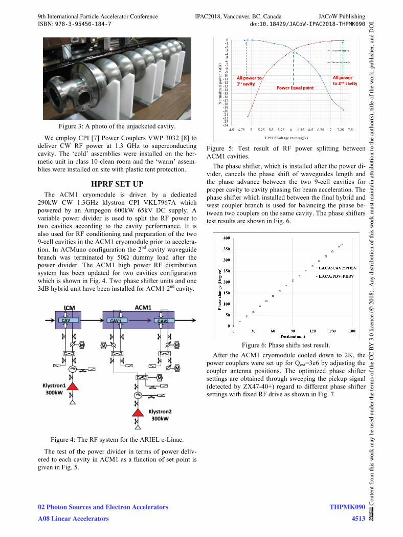
Figure 3: A photo of the unjacketed cavity.
We employ CPI [7] Power Couplers VWP 3032 [8] to deliver CW RF power at 1.3 GHz to superconducting cavity. The ‘cold’ assemblies were installed on the her-metic unit in class 10 clean room and the ‘warm’ assem-blies were installed on site with plastic tent protection.
HPRF SET UP The ACM1 cryomodule is driven by a dedicated
290kW CW 1.3GHz klystron CPI VKL7967A which powered by an Ampegon 600kW 65kV DC supply. A variable power divider is used to split the RF power to two cavities according to the cavity performance. It is also used for RF conditioning and preparation of the two 9-cell cavities in the ACM1 cryomodule prior to accelera-tion. In ACMuno configuration the 2nd cavity waveguide branch was terminated by 50Ω dummy load after the power divider. The ACM1 high power RF distribution system has been updated for two cavities configuration which is shown in Fig. 4. Two phase shifter units and one 3dB hybrid unit have been installed for ACM1 2nd cavity.
Figure 4: The RF system for the ARIEL e-Linac.
The test of the power divider in terms of power deliv-ered to each cavity in ACM1 as a function of set-point is given in Fig. 5.
Figure 5: Test result of RF power splitting between ACM1 cavities.
The phase shifter, which is installed after the power di-vider, cancels the phase shift of waveguides length and the phase advance between the two 9-cell cavities for proper cavity to cavity phasing for beam acceleration. The phase shifter which installed between the final hybrid and west coupler branch is used for balancing the phase be-tween two couplers on the same cavity. The phase shifters test results are shown in Fig. 6.
Figure 6: Phase shifts test result.
After the ACM1 cryomodule cooled down to 2K, the power couplers were set up for Qext=3e6 by adjusting the coupler antenna positions. The optimized phase shifter settings are obtained through sweeping the pickup signal (detected by ZX47-40+) regard to different phase shifter settings with fixed RF drive as shown in Fig. 7.
9th International Particle Accelerator Conference IPAC2018, Vancouver, BC, Canada JACoW PublishingISBN: 978-3-95450-184-7 doi:10.18429/JACoW-IPAC2018-THPMK090
02 Photon Sources and Electron AcceleratorsA08 Linear Accelerators
THPMK0904513
Cont
entf
rom
this
wor
km
aybe
used
unde
rthe
term
soft
heCC
BY3.
0lic
ence
(©20
18).
Any
distr
ibut
ion
ofth
isw
ork
mus
tmai
ntai
nat
tribu
tion
toth
eau
thor
(s),
title
ofth
ew
ork,
publ
isher
,and
DO
I.

Figure 7: Couplers phase balance.
LLRF SET UP The two ACM1 cavities are driven by one power am-
plifier and controlled by a single SEL loop in Vector sum [4] as shown in Fig. 8. The loop phases for both cavities will be kept to a multiple of 2π, irrespective of the actual phasing between the two cavities. Furthermore, the cavi-ties could be running at different gradients based on cavi-ty performance issues. For these reasons an additional attenuator and phase shifter are added to the second cavity feedback path to provide independent control of the loop phase and amplitude.
The two cavities each with individual tuner have to be set up separately before switching to Vector Sum. The power divider will be set up as one cavity mode separate-ly and the tuners position will be optimized and fixed. The power divider will be moved to the optimized posi-tion based the cavities performance. Then adjust each cavity feedback loop phase to meet 2�n condition with the other cavity pick up signal disconnected. φA in Fig. 8 will be adjusted for 1st cavity and φE and Att will be ad-justed for 2nd cavity.
Figure 8: The ACM1 LLRF diagram.
After both loops have the required SEL loop condition and the feedback loops can be connected. The SEL opera-tion with the two cavities and a single source has been
established and the vector sum of the two cavities in the ACM1 has been locked as shown in Fig. 9.
Figure 9: The ACM1 2 cavities locked.
Once the Vector Sum SEL is established the exact phase relationship between cavity 1 rf and cavity 2 rf for optimal acceleration can be achieved by walking the for-ward loop2 phase (φD) and countering with the loop2 feedback phase (ϕE) to maintain the SEL criterion until the correct rf phase is reached.
DISCUSSION Cavity quality factors Q0 are measured based on calo-
rimetric measurements. After RF conditioning both ACM1 cavities Q0=1*1010 was achieved at an accelera-tion gradient Ea=10 MV/m meeting the design goal. In preparation for beam operation the beam will be acceler-ated through the ICM and through the ACM1 cavities individually to get the correct phase relation between the rf and the beam for peak acceleration.
REFERENCES [1] S.R. Koscielniak et al., “Electron Linac photo-fission
driver for the Rare Isotope Program at TRIUMF”, in Proc. IPAC’12, NewOrleans, Louisiana, USA, May 2012, paper MOOBC01, pp.64-66.
[2] M. Marchetto et al., “Commissioning and operation of the ARIEL electron LINAC at TRIUMF”, in Proc. IPAC’15, Richmond, VA, USA, paper WEYC3, pp. 2444–2449.
[3] S. Koscielniak et al., “TRIUMF ARIEL e-Linac Ready for 30 MeV”, in Proc. IPAC’17, Copenhagen, Denmark, May.2017, paper TUPAB022, pp 1361-1364.
[4] R.E. Laxdal et al., “The 30MeV stage of the ARIEL e-Linac”, in Proc. SRF’17, Lanzhou, China, July 2017, paper MOXA03.
[5] N. Muller et al., “TRIUMF’S injector and accelerator cryomodules”, in Proc. SRF’15, Whistler, BC, Cana-da, Sep. 2015, paper THPB115, pp. 1409-1412.
[6] V. Zvyagintsev et al., “Nine-cell elliptical cavity development at TRIUMF”, in Proc. SRF2011, Chi-cago, IL, USA, July.2011, paper MOPO020, pp.107-109.
9th International Particle Accelerator Conference IPAC2018, Vancouver, BC, Canada JACoW PublishingISBN: 978-3-95450-184-7 doi:10.18429/JACoW-IPAC2018-THPMK090
THPMK0904514
Cont
entf
rom
this
wor
km
aybe
used
unde
rthe
term
soft
heCC
BY3.
0lic
ence
(©20
18).
Any
distr
ibut
ion
ofth
isw
ork
mus
tmai
ntai
nat
tribu
tion
toth
eau
thor
(s),
title
ofth
ew
ork,
publ
isher
,and
DO
I.
02 Photon Sources and Electron AcceleratorsA08 Linear Accelerators

[7] http://www.cpii.com/ [8] http://www.cpii.com/docs/datasheets/132/
VWP3032.pdf
9th International Particle Accelerator Conference IPAC2018, Vancouver, BC, Canada JACoW PublishingISBN: 978-3-95450-184-7 doi:10.18429/JACoW-IPAC2018-THPMK090
02 Photon Sources and Electron AcceleratorsA08 Linear Accelerators
THPMK0904515
Cont
entf
rom
this
wor
km
aybe
used
unde
rthe
term
soft
heCC
BY3.
0lic
ence
(©20
18).
Any
distr
ibut
ion
ofth
isw
ork
mus
tmai
ntai
nat
tribu
tion
toth
eau
thor
(s),
title
ofth
ew
ork,
publ
isher
,and
DO
I.