first step-by-step guide for new qa-cad user · (another example: if your drawing requires iso...
TRANSCRIPT
1
First step-by-step guide for new QA-CAD user Vol.5.2:
how to create a FAI report from PDF drawings in QA-CAD 2019
© 2019 Guthrie CAD/GIS Software Pty Ltd.
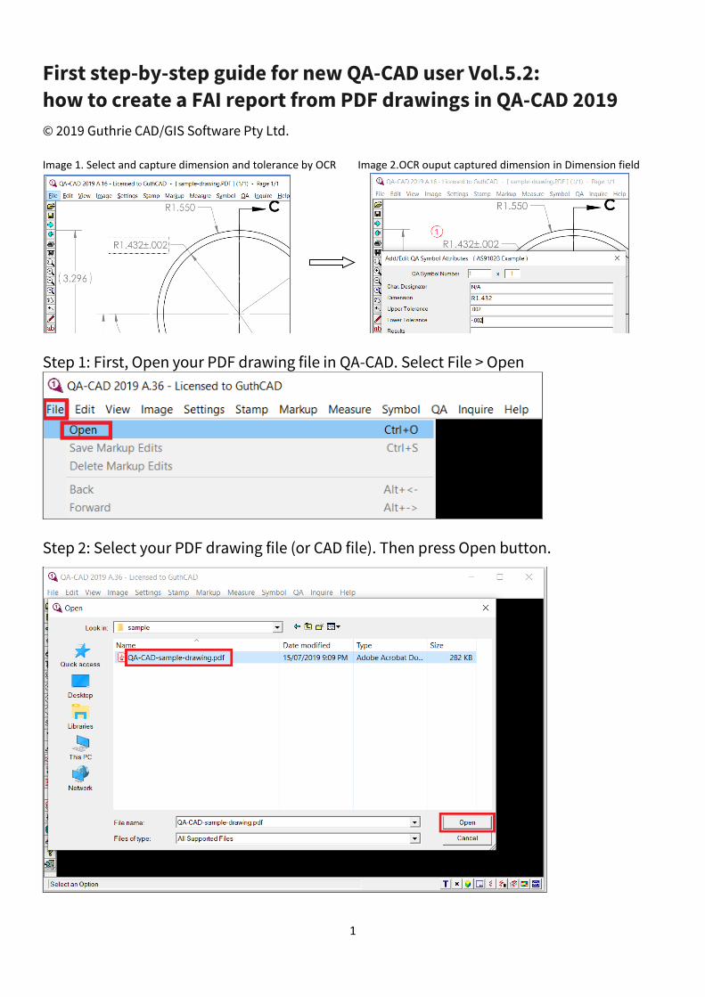
Image 1. Select and capture dimension and tolerance by OCR Image 2.OCR ouput captured dimension in Dimension field
Step 1: First, Open your PDF drawing file in QA-CAD. Select File > Open
Step 2: Select your PDF drawing file (or CAD file). Then press Open button.

2
Step 3: Next, click 'QA' from top menu and select 'QA Settings'.
Step 4: Then ‘QA Settings’ window open. QA-CAD can capture dimension and its specified
tolerance together from your drawing if the dimension and the tolerance are drawn together (for example: ‘.174 ±0.02’). However, if tolerance is unspecified in your drawing
(for example: ‘.174’), QA-CAD can enter tolerance automatically based on dimension in
the drawing. In QA-CAD, there are three automatic tolerance entry methods in case of unspecified tolerance.
Method 1: Select tolerance standard from a built-in QA-CAD tolerance table database.
or
If you find tolerance requirement like the above images in your drawing, you can select required tolerance standard in Gen Tolerance 1 drop-down menu (for example: you can
select 2768-m, which is ISO 2768 General tolerances and its medium(m) tolerance class designation). Then press OK button and proceed to Step 5.
3
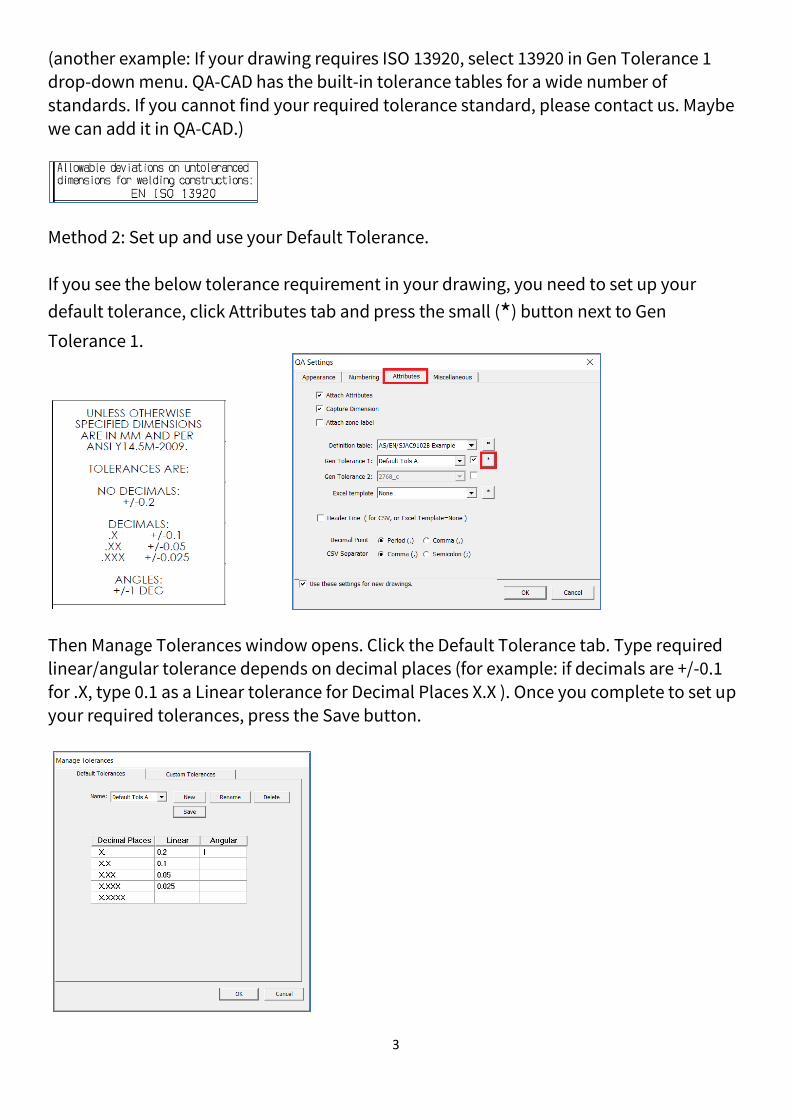
(another example: If your drawing requires ISO 13920, select 13920 in Gen Tolerance 1 drop-down menu. QA-CAD has the built-in tolerance tables for a wide number of
standards. If you cannot find your required tolerance standard, please contact us. Maybe
we can add it in QA-CAD.)
Method 2: Set up and use your Default Tolerance.
If you see the below tolerance requirement in your drawing, you need to set up your
default tolerance, click Attributes tab and press the small (*) button next to Gen
Tolerance 1.
Then Manage Tolerances window opens. Click the Default Tolerance tab. Type required linear/angular tolerance depends on decimal places (for example: if decimals are +/-0.1
for .X, type 0.1 as a Linear tolerance for Decimal Places X.X ). Once you complete to set up
your required tolerances, press the Save button.
4
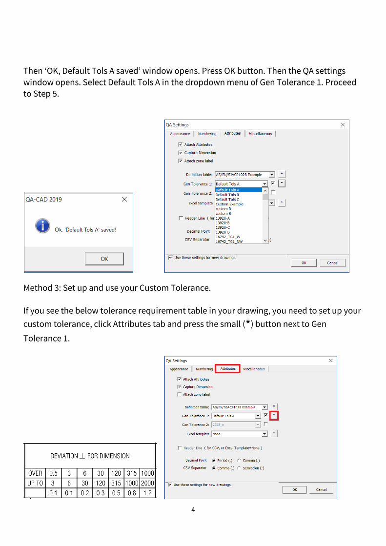
Then ‘OK, Default Tols A saved’ window opens. Press OK button. Then the QA settings
window opens. Select Default Tols A in the dropdown menu of Gen Tolerance 1. Proceed to Step 5.
Method 3: Set up and use your Custom Tolerance.
If you see the below tolerance requirement table in your drawing, you need to set up your
custom tolerance, click Attributes tab and press the small (*) button next to Gen
Tolerance 1.

5
Then Manage Tolerances window opens. Click Custom Tolerances Tab. Input the whole
tolerance requirement table (for example: if OVER 3, UP TO 6 is 0.1, type 3 in Above column and type 6 in Up to column. Then type -0.1 as a lower tolerance and type 0.1 as an
upper tolerance). Please note that the largest ‘Up to’ cell needs to be blank when we
create and save a custom tolerance set. Once you complete to input your required
tolerance table, press Save button.
Then ‘OK, Custom Example saved’ window opens. Press OK button. Then the QA settings
window opens. Select Custom Example in the dropdown menu of Gen Tolerance
1. Proceed to Step 5.

6
Step 5: Tick 'Attach Attributes', 'Capture Dimension', and 'Attach zone label'. Select 'AS/EN/SJAC9102B Example' in Definition table and ''AS/EN/SJAC9102B' in Excel
Template (If you want to output to PPAP Dimensional Test Results form, select PPAP example in Definition table and EXCEL template). Press OK.
Step 6: Select QA > Set/View Zones (If you do not need to reference location, proceed to
step 11).

7
Step 7: A Reference Zones window opens. Press 'Get coordinates from drawing'.
Step 8: Select whole edge of the drawing from left top to right bottom (actually you select
edges with black line in QA-CAD. The red lines in the below image are for your reference.) Then left click once.

8
Step 9: Go back to Reference Zones window. Change Rows, Columns, Letters reference and Origin depends on your drawing (In this same drawing, Rows: 6, Columns:8, Origin is
Bottom Right ). Adjust x1, y1, x2, y2 and press Apply until the grid lines align with the
drawing zone (In this same drawing, x1: 8, y1:7, x2:855, y2:550). Then press OK.
Step 10: Press ‘Zoom In’ button (the red rectangle in the below image). Then move a
mouse pointer to the drawing. When you left-click, you can zoom in your drawing.

9
Then press left-click and hold it. The mouse pointer appearance changes to hand symbol.
Then you can move the drawing (up or down, left or right).
Step 11: Before capturing dimension values from your drawing, let’s check your PDF
drawing to select the best capture method. Select Text from Inquire menu. Then move
the mouse pointer (cross shape) on top of one of the dimensions and left-click once.
If you see the below pop-up window (Drawing does not have any Text/Shapes), your PDF
is image-only type PDF. To capture dimension, tolerance, notes, and GD&T from image-only type PDF, you need to use the OCR feature in QA-CAD. Proceed to Step 16.

10
Alternatively, if you see dimension information in the pop-up window (the below example
images shows “ 3.41” in the red rectangle), your PDF drawing stores dimension, tolerance,
and notes as PDF text data. QA-CAD can extract PDF text data at 100% accuracy (If you need to capture GD&T, please use the OCR method, as GD&T is not text data but image
data in PDF drawing). Proceed to Step12.
Step 12. Now click 'Add QA symbols' from QA menu.
Step 13: Tick Attach Attributes and Capture Dimension Value (Do not tick OCR/GD&T
Capture). Press OK button.

11
Step 14: Your mouse pointer changes and looks like a circle with a plus sign on the
software (as you can see the circle inside the red rectangle in the below image). In this
mode, you can draw balloons on the drawing. Move the circle to where you would like to
place a balloon and left-click once. Then the circle is placed.
Step 15: You can move the plus sign to a dimension value (or text) you would like to
capture (in this example, the plus sign moved towards 3.296). Left-click twice. The target
value is captured and displayed in Dimension field on Add/Edit QA Symbol Attribute
window. Press OK button (complete one balloon and its attributes setting).
Image 15-1. Move the plus sign to a dimension value (or text) you want to capture. Left-click once.

12
Image 15-2. The red ballon is displayed. Left-click once again.
Image 15-3. The target value is captured and displayed in Dimension field on Add/Edit QA Symbol Attribute window.
Press OK button. The upper and lower tolerances are automatically entered by your tolerance settings. (In the below
image, the Upper and Lower Tolerances were filled from 2768_m, one of QA-CAD’s ISO standard tolerance tables).
Proceed to Step 23.

13
Step 16: Now click 'Add QA symbols' from QA menu.
Step 17: Tick Attach Attributes, Capture Dimension and OCR/GD&T Capture. Then press
OK button. The default OCR language setting is eng (English). You can choose deu
(German), fra(French), jpn(Japanese). You can add other language like Chinese, Korean,
Italian, Dutch, etc.
Step 17: Move a mouse pointer to where you want to place a balloon (bubble) and left-click.

14
Then the red balloon is placed.
Step 18: Move the plus sign close to your OCR target. Press a left-click button and hold it.
Now you can draw a rectangle to enclose target (7.10 is the target in the below image).
Once you complete to draw the rectangle, left click twice.

15
Step 19: After that, 'Add/ Edit QA symbol attributes' window opens. You can see the
dimension you selected in Step 13 is inserted in the attributes table. The upper and lower
tolerances are automatically entered by your tolerance settings. (In the below image, the
Upper and Lower Tolerances were filled from Default Tols A set).
Step 20: Then place another balloon and repeat the same step to capture dimension or
text note.

16
Tips: If you would like to capture dimension and tolerance, capture them together.
Tips: You can capture dimension, tolerance, note or GD&T vertically in QA-CAD.
You can also capture max/ min dimension limits, diameter limits and radius limits.

17
Step 21: When you capture the GD&T features control frame, select the whole rectangle of
the GD&T features control frame as you can see from the below image.
Double left-click, once you complete to draw the rectangle as you can see from the above image. The captured GD&T control frame was inserted in dimension field (You can also
select Ture Position in Character designator field).
(If you cannot capture GD&T, check Font Settings if our GD&T font file, GuthCAD-GDT.ttf, has been installed in your PC. If not find the font, re-install QA-CAD and reboot your PC.)

18
Step 22: If the OCR result is not correct, press GD&T input button (if the result is
dimension, tolerance or text note, you can type to correct).
GD&T Data input window opens. Press correct symbol button or type correct numbers
from keyboard (The above OCR result, $52.2, was not correct. So $ was replaced by ⌀ ).
Then press OK button.

19
Step 23. Keep repeating this operation until you finish placing all required balloons on the
drawing.
Step 24. Now choose 'export attributes' from QA menu.

20
Then select AS9102B EXCEL template file and press OK button.
Type your new EXCEL file name and press Save button.
Then press Yes button here.

21
Step 25. As you can see, all values in the balloons are exported to the AS9102 Rev. B
Form3 template.
Step 26. Select File > Save Markup Edits to save the work ballooned drawing (This
operation generates a CVM file which stores all overlaid balloons and markup information.
The original drawing is untouched).

22
Step 27. You can also publish the ballooned drawing to PDF. Select File >> Publish to PDF
Select PDF printer program (e.g. ’PDF-Xchange 3.0’ or ‘Microsoft prints to PDF’) and
proceed PDF output.
Once you publish to PDF, you can see the ballooned PDF in your PDF reader software.
# QA-CAD Purchase Link with Special Discount Coupon (Only available to purchase in our online shop web page) https://guthcad.cleverbridge.com/525/uurl-dcyzvd1e6d
# Other QA-CAD tutorials are available at the below URL. https://www.guthcad.com/tutorials/qa-cad/QA-CAD-download-tutorial.html © 2019 Guthrie CAD/GIS Software Pty Ltd.