qa for helical tomotherapy: report of the aapm task group … · 2010-06-24 · qa for helical...
TRANSCRIPT

1
QA for Helical Tomotherapy: Report of the AAPM Task Group 148
Members:
Katja Langen (Co-chair) Niko Papanikolaou (Co-chair) Walter Grant Richard Crilly Murty Goddu
Chengyu Shi David Followill Chester Ramsey John Balog Gustavo Olivera
Conflict of Interest:
Dr. John Balog owns TomoTherapy stock.
Dr. Katja Langen holds a research agreement with TomoTherapy, Inc.
Dr. Gustavo Olivera is an employee of TomoTherapy Inc. and has a financial interest in TomoTherapy, Inc.
TG-148 overview Introductory chapters. Define TomoTherapy specific terminology. Cover unique aspects of technology and clinical implementation.
Provide QA guidelines for treatment delivery, imaging, and treatment planning system. Recommendations on what to test. Provide examples of how to test.
Provide summary of QA aspects according to frequency.
System Overview
Front view Lateral view
System Overview- MLC System Overview-Operation
Front view Relative opening
time
MLC leaf

2
Three QA chapters
• Treatment Delivery
• Imaging
• Treatment planning system
Three QA chapters
• Treatment Delivery
• Imaging
• Treatment planning system
Treatment Delivery QA
- Mechanical alignments
- Beam parameters
- Synchronicity tests
- Miscellaneous Aspects
- Calibration
Treatment Delivery QA
- Mechanical alignments
- Beam parameters
- Synchronicity tests
- Miscellaneous Aspects
- Calibration
Annual
Treatment Delivery QA - Alignment of Linac
-in x-direction against MLC
-in y-direction against Y-jaw
Look for symmetry
Look for center
Treatment Delivery QA -beam divergence is perpendicular to axis of rotation

3
Mechanical alignment QA
Treatment field centering: test that all fields have common center
Y-Jaw is parallel to plane of rotation
MLC centering and twist: test that MLC is centered and parallel to plane of rotation
Mechanical alignment QA MLC centering and twist: test that MLC is centered and parallel to plane of rotation
Film
Film
Treatment Delivery QA
- Mechanical alignments
- Beam parameters
- Synchronicity tests
- Miscellaneous Aspects
- Calibration
Fan Beam
400 mm 10, 25, or 50 mm
X-direction
Y-direction
no flattening filter
Beam parameter QA X-direction beam profile:
Monthly: consistency
Annual: agreement with model
TG-142 tolerance: 1% (av. difference within 80% of field)
Beam parameter QA Longitudinal beam profile:
Monthly: consistency
Annual: agreement with model
1% FWHM tolerance
4
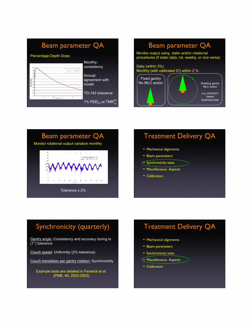
Beam parameter QA Percentage Depth Dose:
Monthly: consistency
Annual: agreement with model
TG-142 tolerance:
1% PDD10 or TMR 10 20
Beam parameter QA Monitor output using static and/or rotational procedures (if static daily, rot. weekly, or vice versa)
Daily (within 3%) Monthly (with calibrated IC) within 2 %
Fixed gantry No MLC action Rotating gantry
MLC action
e.g. phantom-based
treatment plan
Beam parameter QA Monitor rotational output variation monthly
Tolerance ± 2%
Treatment Delivery QA
- Mechanical alignments
- Beam parameters
- Synchronicity tests
- Miscellaneous Aspects
- Calibration
Synchronicity (quarterly)
Gantry angle: Consistency and accuracy during tx (1°) tolerance
Couch speed: Uniformity (2% tolerance)
Couch translation per gantry rotation: Synchronicity
Example tests are detailed in Fenwick et al. (PMB, 49, 2933-2953)
Treatment Delivery QA
- Mechanical alignments
- Beam parameters
- Synchronicity tests
- Miscellaneous Aspects
- Calibration

5
Miscellaneous (monthly)
Interrupted procedure = Uninterrupted procedure (tolerance 3% in delivered dose)
Couch travel: actual distance = digital readout (tolerance 1 mm)
Misc. couch aspects (level, sag, travel perpendicular to treatment plane)
Miscellaneous
Lasers:
Stationary (green)
Movable (red)
Miscellaneous
Lasers:
Daily: Red=Green at initialization
Monthly: Red laser movement=planned movement
Annual (green): Virtual iso to treatment plane = 70 cm x and z location cross in center of imaging plane
Treatment Delivery QA
- QA of mechanical alignments
- QA of beam parameters
- Synchronicity tests
- Miscellaneous Aspects
- Calibration
Calibration
TG-51 equivalent static beam calibration:
Problem: kQ values in TG-51 are a function of PDD @ 100 cm SSD for 10 by 10 cm field
>> not achievable on Tomo (85 cm SSD, max field length 5 cm)
>> IAEA/AAPM joint committee proposed non-compliant beam calibration formalism
(Alfonso et al., Med Phys, 35, 5179-86, 2008)
Calibration Allow two calibration routes:
Machine-specific reference field: msr
Plan class specific reference field: pcsr
(Alfonso et al., Med Phys, 35, 5179-86, 2008)

6
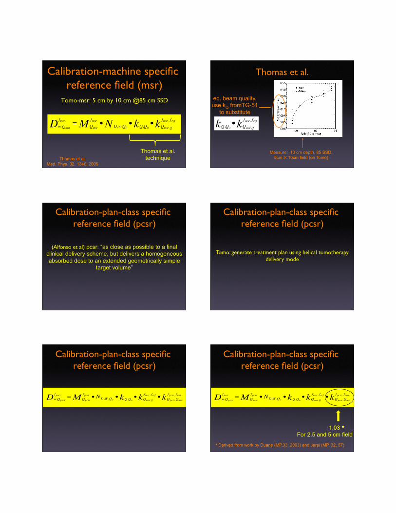
Calibration-machine specific reference field (msr)�
Tomo-msr: 5 cm by 10 cm @85 cm SSD�
Calibration-machine specific reference field (msr)�
Tomo-msr: 5 cm by 10 cm @85 cm SSD�
Corrected reading in msr-field
Calibration-machine specific reference field (msr)�
Tomo-msr: 5 cm by 10 cm @85 cm SSD�
Chamber calibration factor
Calibration-machine specific reference field (msr)�
Tomo-msr: 5 cm by 10 cm @85 cm SSD�
kQ under standard conditions
Calibration-machine specific reference field (msr)�
Tomo-msr: 5 cm by 10 cm @85 cm SSD�
kQ under standard conditions
Calibration-machine specific reference field (msr)�
Tomo-msr: 5 cm by 10 cm @85 cm SSD�
Correction for IC response from standard to msr field
7
Calibration-machine specific reference field (msr)�
Tomo-msr: 5 cm by 10 cm @85 cm SSD�
Thomas et al. technique Thomas et al.
Med. Phys. 32, 1346, 2005
Thomas et al.
Measure: 10 cm depth, 85 SSD, 5cm ✕ 10cm field (on Tomo)
eq. beam quality, use kQ fromTG-51
to substitute
�
Q,Q0k • Qmsr ,Q
fmsr , frefk
Calibration-plan-class specific reference field (pcsr)�
(Alfonso et al) pcsr: “as close as possible to a final clinical delivery scheme, but delivers a homogeneous absorbed dose to an extended geometrically simple
target volume”
Calibration-plan-class specific reference field (pcsr)�
Tomo: generate treatment plan using helical tomotherapy delivery mode
Calibration-plan-class specific reference field (pcsr)�
Calibration-plan-class specific reference field (pcsr)�
�
w,Qpscr
f pscrD = Qpcsr
f pcsrM • ND,W ,Qo• Q,Qok • Qmsr ,Q
fmsr , frefk • Qpcsr ,Qmsr
f pcsr , fmsrk
1.03 ★
For 2.5 and 5 cm field ★ Derived from work by Duane (MP,33, 2093) and Jerai (MP, 32, 57)

8
Calibration
Of the two calibration routes, the calibration via
pcsr-field (rotational delivery) is the relevant
route for tomotherapy.
(Alfonso et al., Med Phys, 35, 5179-86, 2008)
Three QA chapters
• Treatment Delivery
• Imaging
• Treatment planning system
Imaging QA
- Geometry Tests
- Image Quality Tests
- MVCT Dosimetry
Geometry Tests - Image registration and alignment (Daily)
Image misaligned phantom, check registration and
automatic alignment
- MVCT Image Distortions (Monthly)
image phantom, check dimensions and orientation
- Imaging/treatment coordinate coincidence (Annual)
phantom based end-to-end test
1) Scan 2 ) Register -compare to known offsets
3) Align -test automatic couch setup
Example daily imaging test - Test imaging, registration, alignment chain
Tolerance: Consistency within 1 mm
Image Quality (monthly)
- Noise
- Uniformity
- Spatial resolution
- CT-number

9
Image Quality (monthly)
- Noise (SD of HU unit in uniform phantom)
- Uniformity (HU of central vs. peripheral ROI)
- Spatial resolution
- CT-number
Spatial resolution
Resolution of high contrast object:
Tolerance: 1.6 mm object should be resolved
CT number
Important if MVCT is used for dose calculations
Monitor HU for water, lung, bone equivalent
material
MVCT Dosimetry
Measure multiple slice average dose (MSAD) in
Phantom during MVCT scan, IC based
Three QA chapters
• Treatment Delivery
• Imaging
• Treatment planning system
Treatment Planning QA
Geometric validation tests
Dosimetric validation test
Annual phantom-based end-to-end test
Plan specific QA

10
TPS- Geometric test (Annual)
Test CT data import- dimensions, orientation, text
Test integrity of imported structure set -volume and
dimension
TPS- Dosimetric tests (Annual)
Generate phantom-based plans
test with IC measurements
Generate plans for on- and off-axis targets
Generate plans for each commissioned field size
Tolerance: 3%/3 mm
TPS- Patient Plan QA (DQA) Recalculate plan in phantom geometry:
Expectation: 90% of measurements pass 3%/3mm test
Example: “Cheese” phantom,
IC and Film
Summary Chapter:�
Reorganize QA test by frequency
Provide daily, monthly, quarterly and annul QA tables
Provide tables for what to do after major component replacement
Summary Chapter:�Daily
Monthly

11
Quarterly Annual
Component repl. Component repl. After Major Component
Replacement
Component repl. Magnetron/
SSM
Component repl.
Jaw

12
Component repl.
MLC
Where is TG-148 now ?
- Accepted for publication in Med Phys (June 2010)
- Scheduled for August 2010 issue