first year of operational experience with a solar process ...elib.dlr.de/108393/1/2016 shc solsteam...
TRANSCRIPT

1876-6102 © 2016 The Authors. Published by Elsevier Ltd. This is an open access article under the CC BY-NC-ND license (http://creativecommons.org/licenses/by-nc-nd/4.0/).Peer-review by the scientific conference committee of SHC 2015 under responsibility of PSE AGdoi: 10.1016/j.egypro.2016.06.209
Energy Procedia 91 ( 2016 ) 591 – 600
ScienceDirect
SHC 2015, International Conference on Solar Heating and Cooling for Buildings and Industry
First year of operational experience with a solar process steam system for a pharmaceutical company in Jordan
Michael Berger a,*, Mirko Meyer-Grünefeldt b, Dirk Krüger c, Klaus Hennecke c, Marwan Mokhtar a, Christian Zahler a
aIndustrial Solar GmbH, Emmy-Noether-Str. 2, 79110 Freiburg, Germany. bGerman Aerospace Center (DLR), Institute of Solar Research, Plataforma Solar de Almería, Carretera de Senés s/n (km
5),04200,Tabernas,Spain. cGerman Aerospace Center (DLR), Institute of Solar Research, Linder Höhe, 51147 Köln,Germany.
Abstract
Industrial energy consumption represents one third of the total energy used worldwide, significant amount of which is thermal energy. This paper presents details of the recent installation of a linear Fresnel collector to provide saturated steam at 6 bar gauge (166 °C) through Direct Steam Generation (DSG) on the supply level for process heat usage in the Jordanian pharmaceutical manufacturing company RAM Pharma, where first solar steam has been provided in March 2015. This commercial DSG project also represents the first solar DSG plant in MENA. © 2015 The Authors. Published by Elsevier Ltd. Peer-review by the scientific conference committee of SHC 2015 under responsibility of PSE AG.
Keywords: Solar thermal; solar-hybrid; linear Fresnel collector; process heat; supply level; process steam; industrial application; direct steam generation; Jordan; pharmaceutical industry; Industrial Solar
* Corresponding author. Tel.: +49-761-767111-0; fax: +49-761-767111-99.
E-mail address: [email protected]
Available online at www.sciencedirect.com
© 2016 The Authors. Published by Elsevier Ltd. This is an open access article under the CC BY-NC-ND license (http://creativecommons.org/licenses/by-nc-nd/4.0/).Peer-review by the scientific conference committee of SHC 2015 under responsibility of PSE AG

592 Michael Berger et al. / Energy Procedia 91 ( 2016 ) 591 – 600
1. Technical description
1.1. Location and application
RAM Pharmaceutical Industries Co. Ltd is a pharmaceutical manufacturing company with a large variety of pharmaceutical products in Sahab, an industrial area in Amman (Jordan). RAM Pharma decided to install a solar process heat system, with the goal to reduce the fuel consumption of their diesel fired steam boiler by more than 30.000 l diesel annually.
1.2. The solar collector field
In late 2014 Industrial Solar installed 18 LF-11 Fresnel modules [6] for direct steam generation. Industrial Solar’s first commercial direct steam generating system was installed on the roof of the factory in two strings with a total aperture area of 396 m² and a peak capacity of 222 kWth and had been directly connected to the steam supply of the factory. The collector modules have been arranged in two parallel strings of 9 modules each, connected with a cross-over pipe on one side, and thus forming a loop with inlet and outlet on the other side. Each module contains one 4 m long absorber pipe, and 11 primary mirror segments underneath. To form a string out of several modules, the absorber pipes are being welded together, while the primary mirrors are connected by couplings (see Fig. 1).
Fig. 1. Schematic drawing of 3 connected modules of the Industrial Solar's Linear Fresnel Collector LF-11.
1.3. Hydraulic concept
The solar collectors provide saturated steam on the supply level at 6 bar gauge (166 °C) directly to the steam network of RAM, which is mainly used for pill drying in the factory. The direct steam generation has been realized applying the so-called recirculation concept, where the solar field is supplied with a surplus of feed water, so that only a part of the water is evaporated in the absorbers, while the remaining liquid is being recirculated back to the collector inlet [1-4]. This secures enough cooling of the absorbers to avoid overheating, which would occur at a dry-out of the absorbers. Coming from the collector field the water/steam mixture enters a steam drum. In the steam drum the two-phase flow is being separated. Steam leaving at the upper side of the drum is supplied to the RAM factory’s steam network, while the liquid water content is being recirculated into the solar field. The supplied steam is being replaced in the solar collector circuit by feeding in treated water from the RAM makeup water system.
1.4. The steam drum
Apart from its function as a separator the steam drum buffers changes in water content in the piping due to variation of the solar thermal power input. Furthermore the drum with a fill volume of 2000 l has been designed large enough to work as a steam accumulator with a gliding operation pressure range currently between 7 barg and 13.5 barg. With this size and gliding pressure range, the steam accumulator can provide enough storage capacity to

Michael Berger et al. / Energy Procedia 91 ( 2016 ) 591 – 600 593
cover 20 minutes of full load steam production. During phases of missing solar power due to clouds, the steam drum still supplies steam to the steam network by evaporating water.
During discharge of the steam accumulator, the pressure drops until reaching a lower threshold, where the controlled steam valve shuts off the steam supply from the solar collector system to the steam network. The closing point for the valve currently is 1 bar above the operation pressure in the steam network of the industrial process.
Furthermore the drum buffers changes in water content in the piping due to variation of the solar thermal power input. For example while a cloud passes over the solar field, the absorber pipes fill up with liquid water and the drum fill level drops. After the cloud clears away, the liquid water is driven out of the absorber pipes by the developing steam volume, rapidly rising the fill level of the steam drum back to the same state as before. The functionality of the steam drum is described in more detail in [6].
1.5. Piping and instrumentation diagram
Fig. 2. Simplified Piping and Instrumentation Diagram (P&ID) of the DSG plant with recirculation design in Jordan.
2. First year of operation
2.1. Commissioning and general experience from operation
The commissioning of the solar plant has been finished end of March 2015. First steam has been generated and supplied to the steam network on March 17th (photograph see Fig. 3). Since then, the plant is continuously operational. On sunny days during summer and autumn, over the day the conventional steam boiler was not needed, staying in standby, while in the evening it takes over and replaces the solar collector in operation. Due to the steam accumulator, a high stability in operation has been achieved and the installation can be controlled well. The pressure control of the solar system was stable within ±0.05 bar during phases of constant load, while within phases of strong load fluctuations, like due to batch processes, the solar generated steam pressure could be controlled within ±0.5 bar. Due to different production processes, the factory has varying load profiles during the year, so that experience could
594 Michael Berger et al. / Energy Procedia 91 ( 2016 ) 591 – 600
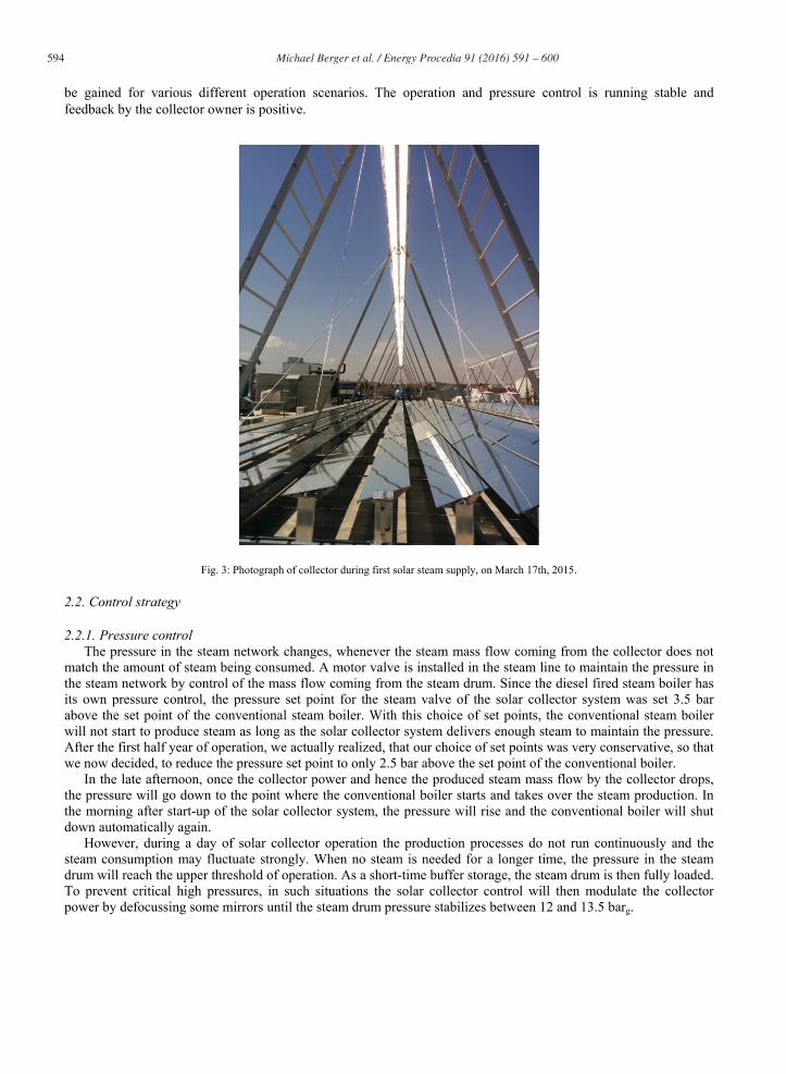
be gained for various different operation scenarios. The operation and pressure control is running stable and feedback by the collector owner is positive.
Fig. 3: Photograph of collector during first solar steam supply, on March 17th, 2015.
2.2. Control strategy
2.2.1. Pressure control The pressure in the steam network changes, whenever the steam mass flow coming from the collector does not
match the amount of steam being consumed. A motor valve is installed in the steam line to maintain the pressure in the steam network by control of the mass flow coming from the steam drum. Since the diesel fired steam boiler has its own pressure control, the pressure set point for the steam valve of the solar collector system was set 3.5 bar above the set point of the conventional steam boiler. With this choice of set points, the conventional steam boiler will not start to produce steam as long as the solar collector system delivers enough steam to maintain the pressure. After the first half year of operation, we actually realized, that our choice of set points was very conservative, so that we now decided, to reduce the pressure set point to only 2.5 bar above the set point of the conventional boiler.
In the late afternoon, once the collector power and hence the produced steam mass flow by the collector drops, the pressure will go down to the point where the conventional boiler starts and takes over the steam production. In the morning after start-up of the solar collector system, the pressure will rise and the conventional boiler will shut down automatically again.
However, during a day of solar collector operation the production processes do not run continuously and the steam consumption may fluctuate strongly. When no steam is needed for a longer time, the pressure in the steam drum will reach the upper threshold of operation. As a short-time buffer storage, the steam drum is then fully loaded. To prevent critical high pressures, in such situations the solar collector control will then modulate the collector power by defocussing some mirrors until the steam drum pressure stabilizes between 12 and 13.5 barg.
Michael Berger et al. / Energy Procedia 91 ( 2016 ) 591 – 600 595
2.2.2. Water mass balance Whenever the solar collector systems supplies steam to the steam network, it loses water, which has to be
replaced by treated feed water. The feed water is taken from the existing feed water treatment plant which also produces the feed water for the conventional steam boiler.
A level meter in the steam drum measures the fill level continuously. The fill level is controlled by the feed water pump, which is currently switched on and off according to the measured fill level. The feed water with a temperature of around 90 °C is directly fed into the steam drum.
Fluctuations in the fill level of the steam drum are caused by changing steam content in the absorber pipes. When steam generation in the solar collector starts i.e. in the morning, the developing steam (low density) in the absorber pipes displaces liquid water (high density), which is driven out towards the steam drum, causing a flush of up to 260 l volume. When, on the other hand, steam generation is interrupted i.e. by a cloud, the absorber pipes will be filled up with liquid water by the recirculation pump, thereby drawing up to 260 l out of the steam drum. By measuring the direct solar irradiation, clouds are detected and the set point of the fill level is adapted according to the current solar steam generation.
In a similar way, the fill level set point is adapted according to the changes in operation temperature due to the gliding pressure in the steam accumulator, to account for water volume expansion in the solar collector system.
The ion concentration is regulated by simple manual blow-down, which is handled manually on schedule. The interval for blow-down is calculated based on the amount of delivered steam. In the beginning, a blow-down ratio of 1:100 has been assumed to be sufficient. After the first year of operation, the ratio can be adapted according to the results of a visual inspection.
2.3. First measurement results
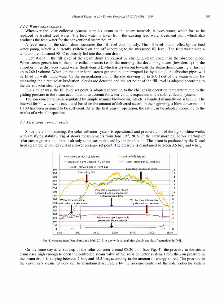
Since the commissioning, the solar collector system is operational and pressure control during sunshine works with satisfying stability. Fig. 4 shows measurements from June 19th, 2015. In the early morning, before start-up of solar steam generation, there is already some steam demand by the production. The steam is produced by the Diesel fired steam boiler, which runs at a lower pressure set point. The pressure is maintained between 3.5 barg and 4 barg.
Fig. 4. Measurement Data from June 19th, 2015. A day with several high clouds and thus fluctuations in DNI.
On the same day after start-up of the solar collector around 08:20 a.m. (see Fig. 4), the pressure in the steam drum rises high enough to open the controlled steam valve of the solar collector system. From then on pressure in the steam drum is varying between 7 barg and 13.5 barg according to the amount of energy stored. The pressure in the customer’s steam network can be maintained accurately by the pressure control of the solar collector system

596 Michael Berger et al. / Energy Procedia 91 ( 2016 ) 591 – 600
within a range from 5.95 barg to 6.05 barg. This control is mainly achieved by the position of the steam outlet motor valve, which is also shown as percentage of opening in Fig. 4.
The power control of the collector defocusses some of the mirrors, once the steam accumulator is fully charged. This can be seen in Fig. 5., which shows measurement data from May 13th, 2015. In the diagram the green curve shows the steam mass flow supplied to the steam grid, while the red curve displays the potential solar collector steam generation, which is calculated from measured DNI, optical efficiency, biaxial incidence angle modifier, current heat loss and current required preheating power. Whenever the green curve is below the red curve, the steam accumulator is charged, or after it is fully charged, mirrors are defocussed. When the green curve is above the red curve, the pressure in the steam drum drops, because more steam is being needed than the collector can provide at this moment. The blue curve shows the requested collector power, which was modulated in steps of 25%. Around 10 a.m. the demand is so low compared to the potential steam generation in the collector that the requested power modulates between 50% and 75%. In the afternoon around 2 p.m., more steam is needed than the collector can provide, so the steam drum as a buffer storage provides the difference.
Fig. 5. Measurement Data from May 13th, 2015. The collector power is actively reduced, once the steam accumulator is fully charged.
3. Installation of an alternative steam separation concept and enhanced monitoring system within the research project “SolSteam”
In the R&D project “SolSteam” [5], funded by the German Federal Ministry for Economic Affairs and Energy (BMWi), and executed by the partners Industrial Solar and the German Aerospace Center (DLR), various designs to integrate solar generated steam into steam networks with a conventional boiler on the supply level have been investigated. To the project DLR is adding its experience from more than 20 years of research with concentrating solar thermal technologies and direct steam generation. The project SolSteam aims to answer the basic technical questions of combining a direct steam generating solar collector with a fossil fuel fired steam generator, thereby laying the foundation for the development of a standard package for hybrid solar-fossil fuel systems, and thus reducing engineering cost in future projects. The project officially started in August 2013 and will continue till mid of 2017. After identifying market requirements, a wide screening of different concepts for a standard hybrid system was realized and the three most promising integration concepts have been chosen [5] for further investigation.
One of these concepts is the system with a steam drum as buffer storage, which had already been realized for RAM Pharma in Jordan. Due to funding from the project SolSteam, that system could now be equipped with a bypass to the steam drum and a second operation concept using a simpler steam separator, a startup vessel and a strong steam trap to swiftly and reliably get rid of slugs after startup or cloud clearance. A level sensor in the

Michael Berger et al. / Energy Procedia 91 ( 2016 ) 591 – 600 597
recirculation line is used to control the feed water pump. View glasses have been added to the piping before and after the steam separator, to observe the two phase flow and the quality of the simpler separator. Two motor three way valves allow to switch between the two operation concepts, so that both concepts can be compared on the same site.
Within the frame of the SolSteam research project, the modified system has now been equipped with additional sensors to allow for a comprehensive monitoring in 2016 and the first half of 2017. The German Aerospace Center (DLR) as scientific partner in cooperation with Industrial Solar adapted sections of the direct steam generation system to improve the monitoring data and to allow for tests of the alternative control strategy. With this improved data acquisition, the steam generation by a solar collector at RAM Pharma can be used as study case during the years 2016 and 2017. Detailed and comprehensive data will be acquired. Also we installed a flow meter in the diesel supply line of the steam boiler, to determine the load profile of the factory.
Fig. 6. Simplified P&ID of the alternative setup with a separator and level meter instead of a steam drum.
Thanks to this research project, 9 Pt100, 8 pressure transmitters, 4 flow meters, 3 differential pressure transmitters, 2 level transmitters and one DNI transmitter are now installed in total, and measurement data are taken with a time step of one second to see effects of transient operating conditions, like for example due to passing clouds. The lessons, which we will certainly learn from this comprehensive monitoring campaign, we will report in future publications.
The adjustments have been installed in October and commissioned in early November 2015. DLR will carry out an evaluation of the collector field optical and thermal performance to provide reliable and precise input data for the detailed modelling of the operation. Steady-state operation and robust start-up and shutdown strategies will be tested. With load changes, the dynamic behavior of the collector field and boiler will be examined so that operation and control strategies can be optimized.
The system behavior under various conditions will be tested in both system configurations. This includes extreme temperatures, power failure, and failure of individual components, such as the tracking system or pump. After demonstration of safe operation of the new separator under all relevant conditions, further process variations will be tested. The process optimization will also take into account the influence of different demand profiles induced by the steam consumption. On completion of the testing phase, the improved routine operation will be monitored to verify the anticipated fuel savings.

598 Michael Berger et al. / Energy Procedia 91 ( 2016 ) 591 – 600
4. Assessing the two phase flow pattern in the absorber pipe during direct steam generation
One focus of any control strategy for direct steam generation is on the two-phase flow in the absorber. In the past Industrial Solar had developed a control strategy avoiding situations like local dryouts or high temperature gradients in the cross section of the absorber pipe wall. Within the research project SoProW, also funded by the BMWi, Industrial Solar is now in co-operation with Fraunhofer ISE for the first time able to validate its calculation models for two phase flow patterns at its R&D system in Freiburg in small scale in summer 2015.
In order to see two-phase flow patterns, Industrial Solar and Fraunhofer ISE temporarily installed a wire mesh sensor, developed and owned by the Helmholtz Zentrum Dresden Rossendorf [8], at the end of the absorber pipe section of Industrial Solar’s test collector in Freiburg. It is not possible to measure the steam quality of the two-phase flow with this kind of sensor in realtime, but during steam generation of the collector, it was possible to determine the slip and the slug or plug frequency as well as the expected flow pattern itself.
Fig. 7: Photographs of the wire mesh sensor by Helmholtz Zentrum Dresden Rossendorf. Inside view (left) and outside view (right side), flanged to the absorber tube outlet.
The sensor consists of a mesh of 16 vertical and 16 horizontal wires. The horizontal and vertical planes of wires have a distance of 2 mm, so that the conductivity at each crossing point is measured and evaluated as “liquid water” or “steam”. The measurement principle and sensor design is described in detail by H. Pietruske and H.-M. Prasser in their publication [8]. As a result, pictures of 16 x 16 pixels are obtained in a very high time resolution. By extrusion of the pictures (see Fig. 8, right side), the flow pattern over time becomes visible.
Fig. 8: Measurement single frame (left side), and extrusion of a frame series over time (right side). The y-axis shows the pixel number (1-16), the
x-axis on the left side picture is the pixel number, on the right side picture it is the frame number with a time resolution of 1 ms per frame. The colour scale ranges from blue=0 (high conductivity, liquid) to red=1 (low conductivity, void or steam).

Michael Berger et al. / Energy Procedia 91 ( 2016 ) 591 – 600 599
The flow patterns in the small system in Freiburg are not representative for bigger commercial systems, but after this successful first experience with such a sensor, we are looking forward to use a wire mesh sensor again in the future in a bigger system like the one in Jordan. First results of evaluation are shown in Fig. 8. Industrial Solar performed measurements at two different levels of operation pressure, 5 barg and 10 barg, varying the mass flow rate from 1,200 kg/h to 2,400 kg/h. In the small system in Freiburg, a slip of 13.0 at 5 barg operation pressure, and 6.6 at 10 barg operation pressure have been evaluated. The collector steam production in the small test facility of 60-80 kg/h had resulted in a rather low steam quality accordingly. The flow pattern was hence mostly stratified/wavy, with occasional plugs. Hence the plug frequency was very little (see Fig. 9).
Fig. 9: Measured plug frequency at the two pressure levels 5 barg and 10 barg.
Through the experiments with the wire mesh sensor, Industrial Solar has been able to validate the results from flow pattern maps of two phase flows. Namely the results match the outcomes of the models by Kattan-Thome-Favrat [9] and that of Steiner [10]. This gives Industrial Solar the confidence to use those models as a basis for their control strategies. For larger, commercial systems, Industrial Solar will always try to avoid the stratified flow regime by going to higher flow velocities.
Acknowledgements
The development partnership for the assembly of the solar steam system in late 2014 with Industrial Solar was part of the develoPPP.de program that Deutsche Gesellschaft für Internationale Zusammenarbeit (GIZ) implements on behalf of the German Federal Ministry for Economic Cooperation and Development (BMZ).
The modification and monitoring of the plant in 2015 to 2017 within the frame of the project “SolSteam” is funded by the German Federal Ministry for Economic Affairs and Energy (BMWi) on the basis of a decision by the German Bundestag (Funding reference number: FKZ 0325545A-C).
The use of the wire mesh sensor to measure two phase flow patterns within the frame of the project “SoProW” was also funded by the German Federal Ministry for Economic Affairs and Energy (BMWi) (Funding reference number: FKZ 0325999B).
References
[1] E. Zarza, L.Gonzalez, A. Morales, E. Rojas, K. Hennecke, M.Eck, O.Goebel, P. Geskes, S. Zunft, F. Lippke, U. Hermann and J. Langenkamp. “DISS Project - Phase I”, Technical Report JOR3-CT95-0058, CIEMAT, DLR, ZSW, PILKINGTON, 1998.
0,020,040,060,080,0100,0120,0140,0160,0
1000 1300 1600 1900 2200
plug
freq
uency[m
Hz]
absorberflow [kg/h]
Frequency of plugs over absorberflow
10barg
5barg

600 Michael Berger et al. / Energy Procedia 91 ( 2016 ) 591 – 600
[2] M. Eck, E. Zarza, M. Eickhoff, J. Rheinländer, and L. Valenzuela. “Applied research concerning the direct steam generation in parabolic troughs”, in Solar Energy, 74(4), pp. 341-351 (2003).
[3] E. Zarza, L. Valenzuela, J. Leon, K. Hennecke, M. Eck, H. Weyers, M. Eickhoff, et al.. “Direct steam generation in parabolic troughs: Final results and conclusions of the DISS project”, in Energy, 29(5), pp. 635-644 (2004).
[4] M. Eck and T. Hirsch, “Dynamics and control of parabolic trough collector loops with direct steam generation”, in Solar Energy, 81(2), pp. 268-279 (2007).
[5] H. Schenk, S. Dieckmann, M. Berger, C. Zahler, O. Stoppok, D. Schulz D. Krüger. “SolSteam - Innovative integration concepts for solar-fossil hybrid process steam generation”, Energy Procedia (69), Elesevier (2015). DOI: doi: 10.1016/j.egypro.2015.03.117. ISSN 1876-6102.
[6] M. Mokhtar, M. Berger, C. Zahler, D. Krüger, H. Schenk and R. Stieglitz. “Direct steam generation for process heat using Fresnel collectors”, in Proceedings of the International Conference of Young Scientists on Innovative Applied Renewable Energy Researches, May 2015, Amman, Jordan
[7] C. Zahler, M. Berger, J.W. Louw. “Industrial Solar Fresnel collectors powering the largest solar cooling system in the middle east for a football stadium”, Solar Paces, 2011.
[8] H. Pietruske, H.-M. Prasser. “Wire-mesh sensors for high-resolving two-phase flow studies at high pressures and temperatures”, Flow Measurement and Instrumentation 18 (2007) 87–94.
[9] John R Thome. Engineering data book iii. Wolverine Tube Inc, 2004. [10] D. Steiner. VDI-Wärmeatlas (VDI Heat Atlas), Section Hbb. Technical Report, Verein Deutscher Ingenieure - Gesellschaft
Verfahrenstechnik und Chemieingenieurwesen, 2006