fitting and feedthrough assembly instructions€¦ · fitting and feedthrough assembly instructions...
TRANSCRIPT

Fitting and Feedthrough Assembly Instructions
+1 716 684 4500 | +1 800 223 2389 | [email protected]
CAUTION: Conax Technologies seal fittings should be installed by suitably qualified personnel in accordance with relevant safety rules and with proper regard to safe working practices.
Conax Technologies seal fittings have lubricant applied at the factory. Substitution of factory-supplied lubricant will affect seal integrity. Lubrication prevents thread galling and minimizes friction between mating metallic components to maximize seal fitting performance when a catalog-specified torque is applied. Weld mount models should be relubricated after the body is welded in place. If the fitting has been cleaned before assembly, it should also be relubricated prior to assembly.
Lubricant should be used any time a seal fitting assembly is opened for replacement or adjustment of the probe(s), wires or sealant. By re-lubricating the fitting body threads and load bearing surface of the cap, proper load transfer (sealant compression) can be achieved. See page 15 for lubrication instructions.
Conax Technologies recommends the use of thread sealant tape or dopant on NPT threads during installation of the fitting to the vessel.
Flange mounted fittings should be assembled prior to mounting to the vessel.
A note on B Caps:
When using a seal fitting assembly with a B Cap, it is sometimes easy to confuse which NPT thread screws into the process side. If installed backwards, leakage will occur between the cap and body straight thread.
A hex notch (as shown below) has been added to the cap to simplify identification. When properly installed, the hex notch will appear on the non-process side of the assembly.
Guidelines for Sealant ReplacementConax Technologies recommends the following procedures to facilitate sealant replacement:
1. Ensure that all system pressurization has been removed before beginning sealant replacement.
2. Untorque and remove the seal fitting cap.
3. Remove the follower and sealant. Depending on the application, the element may also need to be removed.
Follower Removal: Tight manufacturing tolerances are used between the follower OD and the bore of the seal fitting body. As the follower is extracted, a vacuum can be created between the follower and sealant, making it difficult to remove the follower by hand. It may be necessary to clamp the exposed portion of the follower with pliers or a similar tool to gain the additional clamping force needed to remove the follower. If this is necessary, take care to avoid damage to the follower.
Sealant Removal: PTFE, Neoprene, and Viton sealants can generally be removed in one piece. Grafoil and Lava sealants must be removed in multiple pieces, using a rigid “picking” instrument to break apart the sealant. During this process, be careful to avoid damage to the seal fitting body. Deep scratches or gouges may result in potential leak paths during future use of the fitting assembly.
4. Thoroughly clean the internal configuration of the seal fitting body with de-ionized water or cleaning alcohol (depending on the application) to remove any sealant residue.
5. Reassemble per applicable assembly instructions.
A note on Followers with Pins: Many Conax fittings with multiple holes have followers with anti-rotation pins. In our Legacy products, the follower has a key way into which a separate pin (key) is inserted. Conax’s current product line has followers with integral pins. As you read the numbered assembly instructions throughout this document, numbered steps with a letter “a” suffix (14a for example) will explain the process for assembling a fitting with separate pin (key). If a step has a “b” suffix (14b for example), this step describes the assembly process when using a follower with integral pin.
Please Note: Fittings previously purchased may have “Conax” engraved on a cap hex surface in lieu of the hex notch. When properly installed the lettering will appear on the non-process side of the assembly (the cap). Please consult the factory with any questions before installing.
Follower with integral pin
Separate follower and pin

2 +1 716 684 4500 | +1 800 223 2389 | [email protected]
For Hex-Style PG/HPG Series Fittings
For assembly separate from the vessel:
1. Verify that the total probe length is sufficient for your desired immersion.
2. Thread the cap over the probe with the female thread facing the process (see diagram).
3. Thread the follower over the probe. For MPG and PG2 assemblies with bores smaller than 0.093”, the follower may have a larger bore on one side. The larger bore diameter must be adjacent to the cap and the smaller bore diameter adjacent to the sealant.
4. Be sure you are using the correct sealant for your working pressure and temperature. Thread the sealant over the probe with the cone facing the process.
5. Thread the fitting body over the probe.
6. Slide the sealant into the fitting body.
7. Slide the follower after the sealant.
8. Push on the follower until the sealant is firmly seated.
9. Thread the cap on finger tight.
10. Secure the fitting body into a vice.
11. Make the final adjustment of immersion length.
12. Using a torque wrench, tighten the cap to the specified torque (see chart).
13. The assembly is now ready for use. Apply a wrench to the fitting body flats – not the cap – for mounting to the vess.
For assembly directly into a vessel:
1. Verify that the total probe length is sufficient for your desired immersion.
2. Mount the fitting body into the vessel wall. This may be done by threading or welding, depending on the mounting style. When using a weld mount, the fitting must be disassembled prior to welding to protect the sealant.
3. Thread the cap over the probe with the female thread facing the process (see diagram).
4. Thread the follower over the probe so that the follower is between the cap and the process. For MPG and PG2 assemblies with bores smaller than 0.093”, the follower may have a larger bore on one side. The larger bore diameter must be adjacent to the cap and the smaller bore diameter adjacent to the sealant.
5. Be sure you are using the correct sealant for your work-ing pressure and temperature. Thread the sealant over the probe so that the sealant is between the follower and the process, and the cone of the sealant faces the process.
6. Insert the probe through the body into the process.
7. Slide the sealant into the fitting body.
8. Slide the follower after the sealant.
For Large Bore, Flange-Cap PG Series Fittings
For assembly separate from the vessel:
1. Verify that the total length of the cable/probe provides sufficient length for your desired immersion and leads.
2. Thread the flange/cap over the probe (see diagram).
3. Thread the follower over the probe.
4. Be sure you are using the correct sealant for your working pressure and temperature. Thread the sealant over the probe with the cone facing the process. (Sealant may be in more than one layer.)
5. Thread the fitting body over the probe.
6. Slide the sealant into the fitting body.
7. Slide the follower after the sealant.
8. Push on the follower until the sealant is firmly seated.
9. Push on the follower until the sealant is firmly seated.
10. Thread the cap on finger tight.
11. Make the final adjustment of immersion length.
12. Apply a backer wrench to the fitting body flats to prevent rotation during torquing.
13. While holding the backer wrench firmly in place, use a torque wrench to tighten the cap to the specified torque (see chart).
14. The assembly is now ready for use.
PG Series Torque RequirementsPart Number
Neoprene®/Viton® PTFE Lava® Grafoil®ft-lbs N-m ft-lbs N-m ft-lbs N-m ft-lbs N-m
MIC N/O N/O 7-9 in-lbs 0.8-1 45-50
in-lbs 5-5.6 45-50 in-lbs 5-5.6
MPG 55-60 in-lbs 6.2-6.7 55-60
in-lbs 6.2-6.7 75-80 in-lbs 8-9 55-60
in-lbs 6.2-6.7
PG2 30-35 40-48 15-20 20-27 40-45 54-61 35-40 48-54
PG4 55-60 74-82 55-60 74-81 125-140 170-190 90-100 122-136
PG5 55-60 74-82 90-100 122-136 200-220 272-299 180 244
PG6 165-170 224-231 300-325 408-442 N/O N/O N/O N/O
HPG Series Torque RequirementsPart Number
Neoprene®/Viton® PTFE Lava® Grafoil®ft-lbs N-m ft-lbs N-m ft-lbs N-m ft-lbs N-m
HPG2 30 40 7-9 in-lbs 0.8-1 45-50
in-lbs 5-5.6 45-50 in-lbs 5-5.6
HPG4 75 102 55-60 in-lbs 6.2-6.7 75-80
in-lbs 8-9 55-60 in-lbs 6.2-6.7
HPG5 180 244 15-20 20-27 40-45 54-61 35-40 48-54
N/O = Not Offered

3conaxtechnologies.com
9. Slide the flange/cap into place after the follower.
10. Insert the 6 cap screws in place and finger tighten.
11. Secure the fitting body into a vice.
12. Make the final adjustment of immersion length.
13. Using a torque wrench, tighten the cap screws to the specified torque (see chart). The cap screws should be progressively tightened in the order 1-4-2-5-3-6.
14. The assembly is now ready for use. Apply a wrench to the fitting body flats for mounting to the vessel.
For Hex-Style EG Series
EG series seal fittings are shipped from the factory already torqued to the correct value and ready for installation. These instructions are provided in the event you choose to disassemble and need to reassemble the fitting or if you provide your own electrode. Weld mount styles are shipped untorqued, as the fitting must be disassembled prior to welding to protect the sealant.
For assembly separate from the vessel:
1. Be sure you are using the correct sealant for your working pressure and temperature.
2. Thread one ceramic insulator over the electrode (see diagram).
3. Thread the sealant over the electrode. The tapered end of the sealant should face the process. Note: EG-375 and EG-500 Lava sealants use a two-piece cone and cup design. Insert the cup first with the tapered end facing away from the process. Then insert the cone so that the tapered end fits inside the cup. The cone must face the process.
4. Thread the second ceramic insulator over the electrode.
5. Insert the insulators, sealant and electrode as assembled into the fitting body until the ceramic insulator is stopped by the shoulder in the fitting. Hold the electrode to prevent it from dropping through.
6. Thread the follower over the insulator. Seat the undercut edge onto the insulator shoulder.
7. Thread the cap onto the body until finger tight.
8. Secure the fitting body into a vice.
9. Adjust the electrode to the correct position ensuring that the ceramic insulators are firmly seated and aligned.
10. Using a torque wrench, tighten the cap to the specified torque (see chart).
11. Install the nuts and washers on the non-process side of the assembly.
12. Mount the assembly to the vessel. Apply a wrench to the fitting body flats – not the cap – when mounting to the vessel.
13. Install the nuts and washers on the process side of the assembly.
14. Make the appropriate electrical connections to the electrode using ring-tongue, lug-type or spade terminals. These are positioned between the washers. The nuts should be tightened securely.
15. The assembly is now ready for use.
For assembly directly into a vessel:
1. Be sure you are using the correct sealant for your working pressure and temperature.
2. Mount the fitting body into the vessel wall. This may be done by threading or welding, depending on the mounting style. When using a weld mount, the fitting must be disassembled prior to welding to protect the sealant.
3. Thread one ceramic insulator over the electrode (see diagram).
4. Thread the sealant over the electrode. The tapered end of the sealant should face the process. Note: EG-375 and EG-500 Lava sealants use two-piece cone and cup designs. Insert the cup first with the tapered end facing away from the process. Then insert the cone so that the tapered end fits inside the cup. The cone must face the process.
5. Thread the second ceramic insulator over the electrode.
6. Insert the insulators, sealant and electrode as assembled into the cap thread end of the fitting body until the ceramic insulator is stopped by the shoulder in the fitting.
Large Bore PG Series Torque RequirementsPart Number
Viton® Lava® Grafoil® PTFEft-lbs N-m ft-lbs N-m ft-lbs N-m
Standard 1-1/4 NPT
PG7-50 35 48 35 48 35 48 CF
PG7-1000 14 19 35 48 35 48 CF
PG7-75P 35 48 35 48 35 48 CF
PG7-1250 14 19 35 48 35 48 CF
PG7-100P 35 48 35 48 35 48 CF
Weld Neck Mount (Weld Neck Length 1.01")
PG7(SWM7/S316L)-50P 35 48 35 48 35 48 CF
PG7(SWM7/S316L)-1000 14 19 35 48 35 48 CF
PG7(SWM7/S316L)-75P 35 48 35 48 35 48 CF
PG7(SWM7/S316L)-1250 14 19 35 48 35 48 CF
PG7(SWM7/S316L)-100P 35 48 35 48 35 48 CF
C/F = Consult Factory. For PG8 and PG9 torques, consult factory
4 +1 716 684 4500 | +1 800 223 2389 | [email protected]
Hold the electrode to prevent it from dropping through.
7. Thread the follower over the insulator. Seat the undercut edge onto the insulator shoulder.
8. Thread the cap onto the body until finger tight.
9. Adjust the electrode to the correct position ensuring that the ceramic insulators are firmly seated and aligned.
10. Apply a backer wrench to the fitting body flats to prevent rotation during torquing.
11. While holding the backer wrench firmly in place, use a torque wrench to tighten the cap to the specified torque (see chart).
12. Install the nuts and washers on the non-process side of the assembly.
13. Install the nuts and washers on the process side of the assembly.
14. Make the appropriate electrical connections to the electrode using ring-tongue, lug-type or spade terminals. These are positioned between the washers. The nuts should be tightened securely.
15. The assembly is now ready for use.
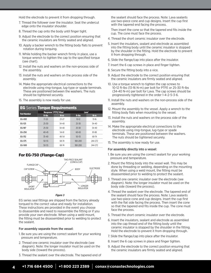
For EG-750 (Flange-Cap)
EG series seal fittings are shipped from the factory already torqued to the correct value and ready for installation. These instructions are provided in the event you choose to disassemble and need to reassemble the fitting or if you provide your own electrode. When using a weld mount, the fitting must be disassembled prior to welding to protect the sealant.
For assembly separate from the vessel:
1. Be sure you are using the correct sealant for your working pressure and temperature.
2. Thread one ceramic insulator over the electrode (see diagram). Note: the longer insulator must be used on the body side (toward the process).
3. Thread the sealant over the electrode. The tapered end of
EG Series Torque RequirementsPart Number
Neoprene®/PTFE/Viton® Lava®ft-lbs N-m ft-lbs N-m
EG-093 17-20 23-27 10-12 13-16
EG-125 25-30 34-40 25-30 34-40
EG-187 25-30 34-40 25-30 34-40
EG-250 40-45 54-61 60-65 81-88
EG-312 35-40 48-54 50-55 68-74
EG-375 50-55 68-74 180-200 244-272
EG-500 50-55 68-74 180-200 244-272
the sealant should face the process. Note: Lava sealants use two-piece cone and cup designs. Insert the cup first with the tapered end facing the process.
Then insert the cone so that the tapered end fits inside the cup. The cone must face the process.
4. Thread the short ceramic insulator over the electrode.
5. Insert the insulators, sealant and electrode as assembled into the fitting body until the ceramic insulator is stopped by the shoulder in the fitting. Hold the electrode to prevent it from dropping through.
6. Slide the flange/cap into place after the insulator.
7. Insert the 6 cap screws in place and finger tighten.
8. Secure the fitting body into a vice.
9. Adjust the electrode to the correct position ensuring that the ceramic insulators are firmly seated and aligned.
10. Use a torque wrench to tighten the cap screws to 10-12 ft-lbs (13-16 N-m) per bolt for PTFE or 25-30 ft-lbs (34-40 N-m) per bolt for Lava. The cap screws should be progressively tightened in the order 1-4-2-5-3-6.
11. Install the nuts and washers on the non-process side of the assembly.
12. Mount the assembly to the vessel. Apply a wrench to the fitting body flats when mounting to the vessel.
13. Install the nuts and washers on the process side of the assembly.
14. Make the appropriate electrical connections to the electrode using ring-tongue, lug-type or spade terminals. These are positioned between the washers. The nuts should be tightened securely.
15. The assembly is now ready for use.
For assembly directly into a vessel:
1. Be sure you are using the correct sealant for your working pressure and temperature.
2. Mount the fitting body into the vessel wall. This may be done by threading or welding, depending on the mounting style. When using a weld mount, the fitting must be disassembled prior to welding to protect the sealant.
3. Thread one ceramic insulator over the electrode (see diagram). Note: the longer insulator must be used on the body side (toward the process).
4. Thread the sealant over the electrode. The tapered end of the sealant should face the process. Note: Lava sealants use two-piece cone and cup designs. Insert the cup first with the flat side facing the process. Then insert the cone so that the tapered end fits inside the cup. The cone must face the process.
5. Thread the short ceramic insulator over the electrode.
6. Insert the insulators, sealant and electrode as assembled into the cap thread end of the fitting body until the ceramic insulator is stopped by the shoulder in the fitting. Hold the electrode to prevent it from dropping through.
7. Slide the flange/cap into place after the insulator.
8. Insert the 6 cap screws in place and finger tighten.
9. Adjust the electrode to the correct position ensuring that the ceramic insulators are firmly seated and aligned.
Figure 3

5conaxtechnologies.com
10. Use a torque wrench to tighten the cap screws to 10-12 ft-lbs (13-16 N-m) per bolt for PTFE or 25-30 ft-lbs (34-40 N-m) per bolt for Lava. The cap screws should be progressively tightened in the order 1-4-2-5-3-6.
11. Install the nuts and washers on the non-process side of the assembly.
12. Install the nuts and washers on the process side of the assembly.
13. Make the appropriate electrical connections to the electrode using ring-tongue, lug-type or spade terminals. These are positioned between the washers. The nuts should be tightened securely.
14. The assembly is now ready for use.
For Hex-Style EGT/HEGPK Series
EGT and HEGPK series seal fittings are shipped from the factory already torqued to the correct value and ready for installation. These instructions are provided in the event you choose to disassemble and need to reassemble the fitting or if you provide your own electrode. When using a weld mount, the fitting must be disassembled prior to welding to protect the PTFE sealant.
For assembly separate from the vessel:
1. Thread the PTFE/PEEK sealant/insulator over the electrode. The tapered end must face the process (see diagram).
2. Insert the sealant/insulator and electrode as assembled into the fitting body until the sealant/insulator is stopped by the shoulder in the fitting. Hold the electrode to prevent it from dropping through the body.
3. Insert the follower.
4. Thread the cap onto the body until finger tight.
5. Secure the fitting body into a vice.
6. Adjust the electrode to the correct position ensuring that the sealant/insulator is firmly seated.
7. Using a torque wrench, tighten the cap to the specified torque (see chart).
8. Install the nuts and washers on the non-process side of the assembly.
9. Mount the assembly to the vessel. Apply a wrench to the fitting body flats – not the cap – when mounting to the vessel.
10. Install the nuts and washers on the process side of the assembly.
11. Make the appropriate electrical connections to the electrode using ring-tongue, lug-type or spade terminals. These are positioned between the washers. The nuts should be tightened securely.
12. The assembly is now ready for use.
For assembly directly into a vessel:
1. Mount the fitting body into the vessel wall. This may be done by threading or welding, depending on the mounting style. When using a weld mount, the fitting must be disassembled prior to welding to protect the sealant.
2. Thread the PTFE sealant/insulator over the electrode. The tapered end must face the process (see diagram).
3. Insert the sealant/insulator and electrode as assembled into the cap thread end of the fitting body until the sealant/insulator is stopped by the shoulder in the fitting. Hold the electrode to prevent it from dropping through the body.
4. Insert the follower.
5. Thread the cap onto the body until finger tight.
6. Adjust the electrode to the correct position ensuring that the sealant/insulator is firmly seated and aligned.
7. Apply a backer wrench to the fitting body flats to prevent rotation during torquing.
8. While holding the backer wrench firmly in place, use a torque wrench to tighten the cap to the specified torque (see chart).
9. Install the nuts and washers on the non-process side of the assembly.
10. Install the nuts and washers on the process side of the assembly.
11. Make the appropriate electrical connections to the electrode using ring-tongue, lug-type or spade terminals. These are positioned between the washers. The nuts should be tightened securely.
12. The assembly is now ready for use.
EGT/HEGPK Series Torque Requirements
Part NumberEGT
PTFEHEGPK PEEK®
ft-lbs N-m ft-lbs N-m
EGT-093 5-6 6-8 – –
EGT/HEGPK-125 10-15 13-20 30 41
EGT/HEGPK-187 25-30 34-40 75 102
EGT/HEGPK-250 25-30 34-41 75 102
EGT/HEGPK-375 35-40 48-54 180 244
EGT/HEGPK-500 35-40 48-54 180 244
EGT-750 75-80 102-108 — —

6 +1 716 684 4500 | +1 800 223 2389 | [email protected]
For EGT-1000 (Flange-Cap)
EGT series seal fittings are shipped from the factory already torqued to the correct value and ready for installation. These instructions are provided in the event you choose to disassemble and need to reassemble the fitting or if you provide your own electrode. When using a weld mount, the fitting must be disassembled prior to welding to protect the PTFE sealant.
For assembly separate from the vessel:
1. Thread the PTFE sealant/insulator over the electrode. The tapered end must face the process (see diagram).
2. Insert the sealant/insulator and electrode as assembled into the fitting body until the sealant/insulator is stopped by the shoulder in the fitting. Hold the electrode to prevent it from dropping through the body.
3. Insert the follower.
4. Slide the flange/cap into place after the follower.
5. Thread the 6 cap screws in place and finger tighten.
6. Secure the fitting body into a vice.
7. Adjust the electrode to the correct position ensuring that the sealant/insulator is firmly seated.
8. Use a torque wrench to tighten the cap screws to 54-60 in-lbs (6-7 N-m) per bolt. The cap screws should be progressively tightened in the order 1-4-2-5-3-6.
9. Install the nuts and washers on the non-process side of the assembly.
10. Mount the assembly to the vessel. Apply a wrench to the fitting body flats when mounting to the vessel.
11. Install the nuts and washers on the process side of the assembly.
12. Make the appropriate electrical connections to the electrode using ring-tongue, lug-type or spade terminals. These are positioned between the washers. The nuts should be tightened securely.
13. The assembly is now ready for use.
For assembly directly into a vessel:
1. Mount the fitting body into the vessel wall. This may be done by threading or welding, depending on the mounting style. When using a weld mount, the fitting must be disassembled prior to welding to protect the sealant.
2. Thread the PTFE sealant/insulator over the electrode. The tapered end must face the process (see diagram).
3. Insert the sealant/insulator and electrode as assembled into the fitting body until the sealant/insulator is stopped
by the shoulder in the fitting. Hold the electrode to prevent it from dropping through the body.
4. Insert the follower.
5. Slide the flange/cap into place after the follower.
6. Insert the 6 cap screws in place and finger tighten.
7. Adjust the electrode to the correct position ensuring that the sealant/insulator is firmly seated and aligned.
8. Use a torque wrench to tighten the cap screws to 54-60 in-lbs (6-7 N-m) per bolt. The cap screws should be progressively tightened in the order 1-4-2-5-3-6.
9. Install the nuts and washers on the non-process side of the assembly.
10. Install the nuts and washers on the process side of the assembly.
11. Make the appropriate electrical connections to the electrode using ring-tongue, lug-type or spade terminals. These are positioned between the washers. The nuts should be tightened securely.
12. The assembly is now ready for use.
For MK Series
For assembly separate from the vessel:
1. Verify that the total length of the wire/probe provides sufficient length for your desired immersion and leads.
2. Thread the cap over the probe with the male thread facing the process (see diagram).
3. Thread the ferrule over the probe with the cone facing the process.
4. Thread the fitting body over the probe.
5. Slide the ferrule into the fitting body.
6. Thread the cap on finger tight.
7. Secure the fitting body into a vice.
8. Make the final adjustment of immersion length.
9. Using a torque wrench, tighten the cap to the specified torque (see chart).
10. The assembly is now ready for use. Apply a wrench to the fitting body flats for mounting to the vessel.
For assembly directly into a vessel:
1. Verify that the total length of the wire/probe provides sufficient length for your desired immersion and leads.
2. Mount the fitting body into the vessel wall.
3. Thread the cap over the probe with the male thread facing the process (see diagram).
4. Thread the ferrule over the probe with the cone facing the process.

7conaxtechnologies.com
MK Series Torque RequirementsPart Number
Torqueft-lbs N-m
MK-062-A 10 14
MK-125-A 12 16
MK-187-A 18 24
MK-250-A 30 41
MK-375-A 50 68
5. Insert the probe through the body into the process.
6. Insert the ferrule into the fitting body.
7. Thread the cap on finger tight.
8. Make the final adjustment of immersion length.
9. Apply a backer wrench to the fitting body flats to prevent rotation during torquing.
10. While holding the backer wrench firmly in place, use a torque wrench to tighten the cap to the specified torque (see chart).
11. The assembly is now ready for use.
For TG SeriesFor Models TG-14-1; TG-20, 2 & 4 hole; TG-24, 2 & 4 hole, all MTGs
For assembly separate from the vessel:
1. Verify that the total length of wire provides a sufficient length for your desired immersion and leads.
2. Thread the cap over the wires.
3. Thread the follower over the wires so that keyway faces the cap.
4. Thread on insulator #4 (see diagram).
5. Thread on insulator #3.
6. Be sure you are using the correct sealant for your working pressure and temperature. Thread on the sealant so that the cone of the sealant faces the process.
7. Thread on insulator #2.
8. Thread insulator #1 over the wire.
9. Pass the process side of the wires through the body.
10. Slide the insulators and sealant into the body.
11. Slide the follower on over insulator #4 and insulator #3 until it completely covers insulator #3.
12. Push on the follower until the sealant and insulators are firmly seated. Be careful not to crimp the wires between the insulators and sealant.
13a. Align the follower keyway and body keyway to create a full keyway, then place pin into keyway.
13b. Align follower with integral pin with body keyway, then insert follower/integral pin into the fitting body/keyway.
14. Thread the cap on finger tight.
15. Secure the feedthrough body into a vice.
16. Adjust the wires to the correct position.
17. Using a torque wrench, tighten the cap to the specified torque (see chart).
18. The assembly is now ready for use. Apply a wrench to the feedthrough body flats – not the cap – for mounting to the vessel.
For assembly directly into a vessel:
1. Verify that the total length of wire provides a sufficient length for your desired immersion and leads.
2. Mount the feedthrough body into the vessel wall. This may be done by threading or welding, depending on the mounting style. When using a weld mount, the feedthrough must be disassembled prior to welding to protect the sealant.
3. Thread the cap over the wires.
4. Thread the follower over the wires so that keyway faces the cap.
5. Thread on insulator #4 (see diagram).
6. Thread on insulator #3.
7. Be sure you are using the correct sealant for your working pressure and temperature. Thread on the sealant so that the cone of the sealant faces the process.
8. Thread on insulator #2.
9. Thread insulator #1 over the wire.
10. Pass the process side of the wires through the body.
11. Slide the insulators and sealant into the body.
12. Slide the follower on over insulator #4 and insulator #3 until it completely covers insulator #3.
13. Push on the follower until the sealant and insulators are firmly seated. Be careful not to crimp the wires between the insulators and sealant.
14a. Align the follower keyway and body keyway to create a full keyway, then place pin into keyway.
14b. Align follower with integral pin with body keyway, then insert follower/integral pin into the fitting body/keyway.
15. Thread the cap on finger tight.
16. Adjust the wires to the correct position.
17. Apply a backer wrench to the feedthrough body wrench flats to prevent rotation during torquing.
18. While holding the backer wrench firmly in place, use a torque wrench to tighten the cap to the specified torque (see chart).
19. The assembly is now ready for use.

8 +1 716 684 4500 | +1 800 223 2389 | [email protected]
For TG SeriesFor Models TG-8-2; TG-14, 2-8 hole; TG-18, 6 & 8 hole; TG-20, 6-16 hole
For assembly separate from the vessel:
1. Verify that the total length of wire provides a sufficient length for your desired immersion and leads.
2. Thread insulator #4 (see diagram) over the wire.
3. Thread the cap over the wire.
4. Thread the follower over the wires so that the keyway faces the cap.
5. Thread on insulator #3.
6. Be sure you are using the correct sealant for your working pressure and temperature. Thread on the sealant with the cone facing the process.
7. Thread on insulator #2.
8. Insert the wires and insulator assembly through the process end of the feedthrough body.
9. Thread insulator #1 over the wire until the insulator is stopped by the body shoulder.
10. Slide insulator #2 into the body until the insulator is stopped by the body shoulder.
11. Slide the sealant, followed by the follower, into the body.
12. Push on the follower until the sealant and insulators are firmly seated. Be careful not to crimp the wires between the insulators and sealant.
13. Slide insulator #4 so that it butts against the follower.
14a. Align the follower keyway and body keyway to create a full keyway, then place pin into keyway.
14b. Align follower with integral pin with body keyway, then insert follower/integral pin into the fitting body/keyway.
15. Thread the cap on finger tight.
16. Secure the feedthrough body into a vice.
17. Adjust the wires to the correct position.
18. Using a torque wrench, tighten the cap to the specified torque (see chart).
19. The assembly is now ready for use. Apply a wrench to the feedthrough body flats – not the cap – for mounting to the vessel.
For assembly directly into a vessel:
1. Verify that the total length of wire provides a sufficient length for your desired immersion and leads.
2. Mount the feedthrough body into the vessel wall. This may be done by threading or
welding, depending on the mounting style. When using a weld mount, the feedthrough must be disassembled prior to welding to protect the sealant.
3. Thread insulator #4 (see diagram) over the wire.
4. Thread the cap over the wire.
5. Thread the follower over the wires so that the keyway faces the cap.
6. Thread on insulator #3.
7. Be sure you are using the correct sealant for your working pressure and temperature. Thread on the sealant with the cone facing the process.
8. Thread on insulator #2.
9. Insert the wires and insulator assembly through the process end of the feedthrough body.
10. Thread insulator #1 over the wire from the inside of the vessel and through the process side of the feedthrough body until the insulator is stopped by the body shoulder.
11. Slide insulator #2 into the body until the insulator is stopped by the body shoulder.
12. Slide the sealant, followed by the follower, into the body.
13. Push on the follower until the sealant and insulators are firmly seated. Be careful not to crimp the wires between the insulators and sealant.
14. Slide insulator #4 so that it butts against the follower.
15a. Align the follower keyway and body keyway to create a full keyway, then place pin into keyway.
15b. Align follower with integral pin with body keyway, then insert follower/integral pin into the fitting body/keyway.
16. Thread the cap on finger tight.
17. Adjust the wires to the correct position.
18. Apply a backer wrench to the feedthrough body wrench flats to prevent rotation during torquing.
19. While holding the backer wrench firmly in place, use a torque wrench to tighten the cap to the specified torque (see chart).
20. The assembly is now ready for use.
TG Series Torque RequirementsPart Number Number
of HolesNeoprene® Viton® PTFE Lava®
ft-lbs N-m ft-lbs N-m ft-lbs N-m ft-lbs N-m
MTG-24 2,4 20-25 27-34 20-25 27-34 20-25 27-34 30-35 40-48
MTG-20 2,4 20-25 27-34 20-25 27-34 20-25 27-34 30-35 40-48
MTG-14 1 20-25 27-34 20-25 27-34 20-25 27-34 30-35 40-48
TG-24 2,4 25-30 34-40 25-30 34-40 30-35 40-48 40-45 54-61
TG-20 2,4 25-30 34-40 25-30 34-40 30-35 40-48 40-45 54-61
TG-20 6,8 45-50 61-68 45-50 61-68 50-55 68-74 125-140 170-190
TG-20 16 75-85 102-115 75-85 102-115 75-85 102-115 200-220 272-299
TG-18 6,8 45-50 61-68 45-50 61-68 50-55 68-74 125-140 170-190
TG-14 1 25-30 34-40 25-30 34-40 30-35 40-48 40-45 54-61
TG-14 2,3,4 45-50 61-68 45-50 61-68 50-55 68-74 125-140 170-190
TG-14 6,8 75-85 102-115 75-85 102-115 75-85 102-115 200-220 272-299
TG-8 2 75-85 102-115 75-85 102-115 75-85 102-115 200-220 272-299
TG-20 24 NA NA 95-100 129-136 95-100 129-136 300-310 408-422

9conaxtechnologies.com
Model TGF – TG Assembly with High Temperature Wire Model TG-24T – TG Assembly with 24AWG PTFE Insulated Wire
Model TGF and TG-24T series seal feedthroughs are shipped from the factory already torqued to the correct value and ready for installation. These instructions are provided for installation of the assembled feedthrough. In the event you choose to disassemble and need to reassemble the feedthrough, see the instructions for the MHC Series.
When using a weld mount, the feedthrough must be disassembled prior to welding to protect the sealant.
Recommended Method Using a Nipple-UnionRequired Materials: Pipe Nipple, Schedule 40, Carbon Steel or Stainless Steel Union, 150 lb., Carbon Steel or Stainless Steel.
For longer length lead wires, this mounting method eliminates additional stress and potential wire entanglement caused by the rotation of the wires during the mounting operation.
1. Install the nipple and half union assembly into the vessel wall.
2. Uncoil and straighten the leads on the pressure side of the feedthrough.
3. Thread the mating half of the union over the leads.
4. Assemble the union onto the mounting thread of the seal feedthrough. Use the feedthrough body flats to hold/secure the feedthrough while mating the feedthrough with the union.
5. Pass the leads through the nipple-union assembly mounted on the vessel wall.
6. Position the two parts of the union and assemble the nipple-union assembly.
7. Remove wire markers on the process side after installation, as the adhesive-backed material could contaminate the process (depending on the application).
Optional Method for TG-24T1. Uncoil and straighten the leads on the pressure side.
2. Pass the leads through the mounting thread port on the vessel.
3. Screw/tighten the feedthrough into the vessel. Apply the wrench to the feedthrough body flats, not the cap.
4. Remove wire markers on the process side after installation, as the adhesive-backed material could contaminate the process (depending on the application).
For High Density Assemblies – HD Series
1. HD feedthrough may be supplied preinstalled on fitting either factory-torqued or loose (HD held in place with temporary tape). If factory-torqued, the HD/feedthrough assembly is ready for installation into your process. If the fitting is not factory-torqued onto the HD(s), then you should turn to the installation instructions for the appropriate fitting to review the proper torque rate to apply following installation of the feedthrough to the process and the HD to the fitting by following the following steps.
2. Secure the feedthrough body into the vessel wall. The remaining feedthrough parts are best assembled on a flat surface such as a work table or a clean floor.
3. Install the seat and insulators if applicable, depending on the feedthrough type (see instructions for that feedthrough type).
4. Install the sealant.
5. Install the follower and pin if applicable.
6. Insert the leads through the feedthrough body and insert the high density assembly (as now assembled) into the body until the seat or insulator is firmly seated. Position the stainless steel sheath so that an approximately equal amount extends on each side of the feedthrough.
7. Thread the cap on finger tight.
8. Apply a backer wrench to the feedthrough body flats. Using a torque wrench, apply the appropriate torque for that feedthrough style.
9. The assembly is now ready for use.
TGF Series Torque RequirementsCatalog Number
Number of Holes
Viton®/PTFEft-lbs N-m
MTG-F 2,4 72-78 in-lbs 8-9
TG-24F 2,4 10-12 13-16
TG-20F 2,4 10-12 13-16
TG-20F-14 2,4 25-30 34-40
TG-20F 6,8 25-30 34-40
TG-20F 16 60-65 81-88
TG-20F 24 70-75 95-102
TG-24T Series Torque RequirementsCatalog Number
Number of Holes
Torque for PTFE Sealant w/ T/C Wire
Except Type T
Torque for Grafoil® Sealant and PTFE w/ Copper
or Type T Wireft-lbs N-m ft-lbs N-m
MTG-24T 2,4 20-25 24-34 72-78 in-lbs 8-9
TG-24T 2,4 30-35 40-48 10-12 13-16
TG-24T 6,8 50-55 67-74 25-30 34-40
TG-24T 12,16 75-85 102-115 60-65 81-88
TG-24T 24 95-100 129-136 70-75 95-102
SEAL FITTING

10 +1 716 684 4500 | +1 800 223 2389 | [email protected]
MHC Series
For assembly separate from the vessel:
1. Verify that the total length of wire/probes provides a sufficient length for your desired immersion and leads.
2. Thread the cap over the wires.
3. Thread the follower over the wires so that the keyway faces the cap.
4. Thread on insulator #2 (see diagram).
5. Be sure you are using the correct sealant for your working pressure and temperature. Thread on the sealant with the cone facing the process.
6. Thread on insulator #1.
7. Pass the process side of the wires/probes through the body.
8. Slide the insulators, sealant and follower into the body.
9. Push on the follower until the sealant and insulators are firmly seated. For wire assemblies, be careful not to crimp the wires between the insulators and sealant.
10a. Align the follower keyway and body keyway to create a full keyway, then place pin into keyway.
10b. Align follower with integral pin with body keyway, then insert follower/integral pin into the fitting body/keyway.
11. Thread the cap on finger tight.
12. Secure the feedthrough body into a vice.
13. Adjust the wires to the correct position.
14. Using a torque wrench, tighten the cap to the specified torque (see chart).
15. The assembly is now ready for use. Apply a wrench to the feedthrough body flats – not the cap – for mounting to the vessel.
For assembly directly into a vessel:
1. Verify that the total length of wire/probes provides a sufficient length for your desired immersion and leads.
2. Mount the feedthrough body into the vessel wall. This may be done by threading or welding, depending on the mounting style. When using a weld mount, the feedthrough must be disassembled prior to welding to protect the sealant.
3. Thread the cap over the wires.
4. Thread the follower over the wires so that the keyway faces the cap.
5. Thread on insulator #2 (see diagram).
6. Be sure you are using the correct sealant for your working pressure and temperature. Thread on the sealant with the cone facing the process.
PL Series
PL feedthroughs are shipped from the factory already torqued to the correct value and ready for installation. These instructions are provided in the event you choose to disassemble and reassemble the feedthrough. Weld mount styles are shipped untorqued as the feedthrough must be diassembled prior to welding to protect the sealant. PL feedthroughs are provided with PTFE sleeves on the body and cap to protect against wire chafing. Do not remove these sleeves. When using a Grafoil sealant, the insulators on PL feedthroughs are chamfered around the holes. Insulators for other sealants are not chamfered. Do not interchange. For assembly separate from the vessel:
1. Verify that the total length of wire provides a sufficient length for your desired immersion and leads.
2. Thread on insulator #1 (see diagram).
7. Thread on insulator #1.
8. Pass the process side of the wires/probes through the body.
9. Slide the insulators, sealant and follower into the body.
10. Push on the follower until the sealant and insulators are firmly seated. For wire assemblies, be careful not to crimp the wires between the insulators and sealant.
11a. Align the follower keyway and body keyway to create a full keyway, then place pin into keyway.
11b. Align follower with integral pin with body keyway, then insert follower/integral pin into the fitting body/keyway.
12. Thread the cap on finger tight.
13. Adjust the wires to the correct position.
14. Apply a backer wrench to the gland body wrench flats to prevent rotation during torquing.
15. While holding the backer wrench firmly in place, use a torque wrench to tighten the cap to the specified torque (see chart).
16. The assembly is now ready for use.
MHC Series Torque RequirementsCatalog Number
Neoprene® Viton® PTFE Lava® Grafoil®ft-lbs N-m ft-lbs N-m ft-lbs N-m ft-lbs N-m ft-lbs N-m
MHC1 20-25 27-34 20-25 27-34 20-25 27-34 30-35 40-48 25-30 27-34
MHC2-020 25-30 34-40 25-30 34-40 30-35 40-48 40-45 61-68 35-40 48-54
MCH2-032 25-30 34-40 25-30 34-40 30-35 40-48 40-45 61-68 35-40 48-54
MHC2-040 25-30 34-40 25-30 34-40 30-35 40-48 40-45 61-68 40-45 61-68
MHC2-062 25-30 34-40 25-30 34-40 30-35 40-48 40-45 61-68 40-45 61-68
MCH4 45-50 61-68 45-50 61-68 50-55 68-74 125-140 170-190 90-100 122-136
MHC5 75-85 102-115 75-85 102-115 75-85 102-115 200-220 272-299 150-165 204-224
MHC5-032-24 N/O N/O 95-100 129-136 95-100 129-136 300-310 408-422 250-265 340-360
11conaxtechnologies.com
3. Be sure you are using the correct sealant for your working pressure and temperature. Thread on the sealant with the cone facing the process.
4. Thread on insulator #2.
5. Slide on the follower, so that the keyway faces the cap.
6. Pass the process side of the wires through the body.
7. Push on the follower until the sealant and insulators are firmly seated. Be careful not to crimp the wires between the insulators and sealant.
8a. Align the follower keyway and body keyway to create a full keyway, then place pin into keyway.
8b. Align follower with integral pin with body keyway, then insert follower/integral pin into the fitting body/keyway.
9. Thread the cap on finger tight.
10. Secure the feedthrough body into a vice.
11. Adjust the wires to the correct position.
12. Using a torque wrench, tighten the cap to the specified torque (see chart).
13. The assembly is now ready for use. Apply a wrench to the feedthrough body flats – not the cap – for mounting to the vessel.
For assembly directly into a vessel:
1. Verify that the total length of wire/probes provides a sufficient length for your desired immersion and leads.
2. Mount the feedthrough body into the vessel wall. This may be done by threading or welding, depending on the mounting style. When using a weld mount, the feedthrough must be disassembled prior to welding to protect the sealant.
3. Thread on insulator #1 (see diagram).
4. Be sure you are using the correct sealant for your working pressure and temperature. Thread on the sealant with the cone facing the process.
5. Thread on insulator #2.
6. Slide on the follower, so that the keyway faces the cap.
7. Pass the process side of the wires through the body.
8. Push on the follower until the sealant and insulators are firmly seated. Be careful not to crimp the wires between the insulators and sealant.
9a. Align the follower keyway and body keyway to create a full keyway, then place pin into keyway.
9b. Align follower with integral pin with body keyway, then insert follower/integral pin into the fitting body/keyway.
10. Thread the cap on finger tight.
11. Adjust the wires to the correct position.
12. Apply a backer wrench to the feedthrough body flats to prevent rotation during torquing.
13. While holding the backer wrench firmly in place, use a torque wrench to tighten the cap to the specified torque (see chart).
14. The assembly is now ready for use.
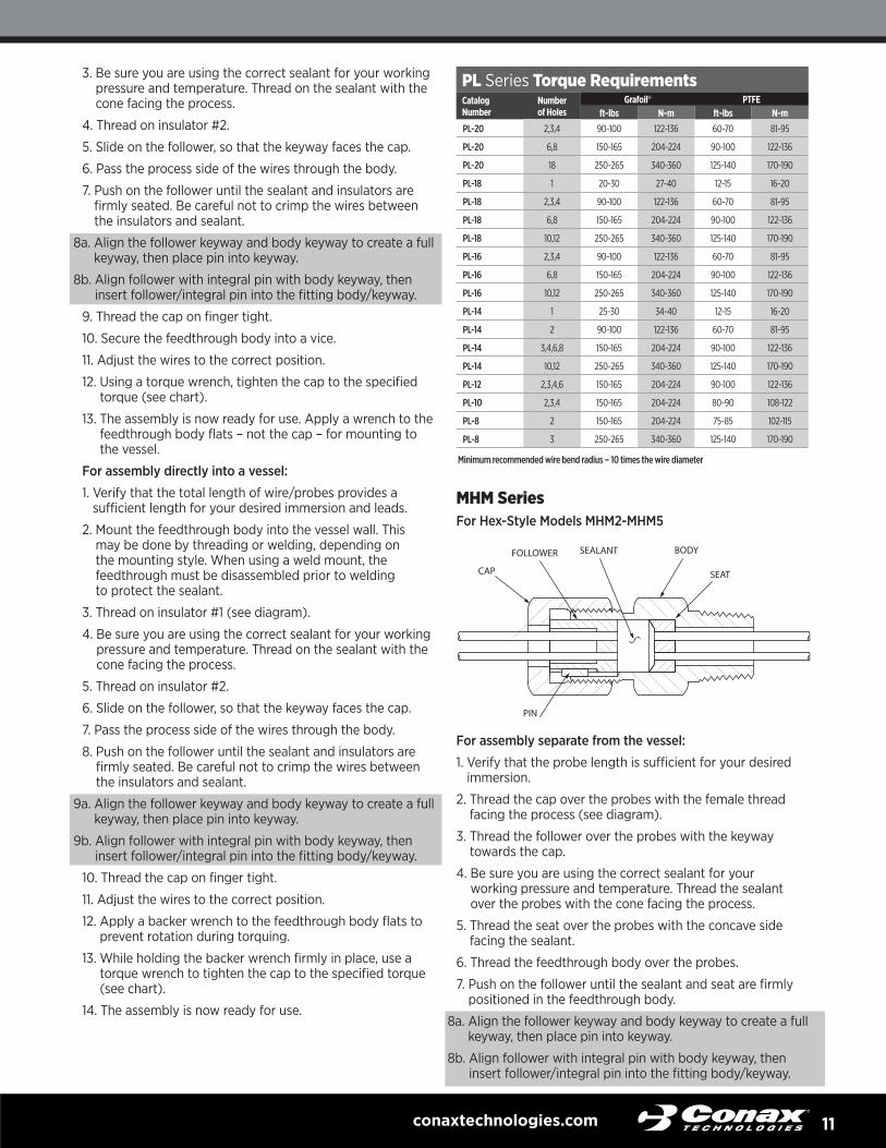
MHM SeriesFor Hex-Style Models MHM2-MHM5
For assembly separate from the vessel:
1. Verify that the probe length is sufficient for your desired immersion.
2. Thread the cap over the probes with the female thread facing the process (see diagram).
3. Thread the follower over the probes with the keyway towards the cap.
4. Be sure you are using the correct sealant for your working pressure and temperature. Thread the sealant over the probes with the cone facing the process.
5. Thread the seat over the probes with the concave side facing the sealant.
6. Thread the feedthrough body over the probes.
7. Push on the follower until the sealant and seat are firmly positioned in the feedthrough body.
8a. Align the follower keyway and body keyway to create a full keyway, then place pin into keyway.
8b. Align follower with integral pin with body keyway, then insert follower/integral pin into the fitting body/keyway.
PL Series Torque RequirementsCatalog Number
Number of Holes
Grafoil® PTFEft-lbs N-m ft-lbs N-m
PL-20 2,3,4 90-100 122-136 60-70 81-95
PL-20 6,8 150-165 204-224 90-100 122-136
PL-20 18 250-265 340-360 125-140 170-190
PL-18 1 20-30 27-40 12-15 16-20
PL-18 2,3,4 90-100 122-136 60-70 81-95
PL-18 6,8 150-165 204-224 90-100 122-136
PL-18 10,12 250-265 340-360 125-140 170-190
PL-16 2,3,4 90-100 122-136 60-70 81-95
PL-16 6,8 150-165 204-224 90-100 122-136
PL-16 10,12 250-265 340-360 125-140 170-190
PL-14 1 25-30 34-40 12-15 16-20
PL-14 2 90-100 122-136 60-70 81-95
PL-14 3,4,6,8 150-165 204-224 90-100 122-136
PL-14 10,12 250-265 340-360 125-140 170-190
PL-12 2,3,4,6 150-165 204-224 90-100 122-136
PL-10 2,3,4 150-165 204-224 80-90 108-122
PL-8 2 150-165 204-224 75-85 102-115
PL-8 3 250-265 340-360 125-140 170-190
Minimum recommended wire bend radius – 10 times the wire diameter

12 +1 716 684 4500 | +1 800 223 2389 | [email protected]
9. Thread the cap on finger tight.
10. Secure the feedthrough body into a vice.
11. Make the final adjustment of immersion length.
12. Using a torque wrench, tighten the cap to the specified torque (see chart).
13. The assembly is now ready for use. Apply a wrench to the feedthrough body flats – not the cap – for mounting to the vessel.
For assembly directly into a vessel:
1. Verify that the probe length is sufficient for your desired immersion.
2. Mount the feedthrough body into the vessel wall. This may be done by threading or welding, depending on the mounting style. When using a weld mount, the feedthrough must be disassembled prior to welding to protect the sealant.
3. Thread the cap over the probes with the female thread facing the process (see diagram).
4. Thread the follower over the probes with the keyway towards the cap.
5. Be sure you are using the correct sealant for your working pressure and temperature. Thread the sealant over the probes with the cone facing the process.
6. Thread the seat over the probes with the concave side facing the sealant.
7. Insert the probes through the body into the process.
8. Push on the follower until the sealant and seat are firmly positioned in the feedthrough body.
9a. Align the follower keyway and body keyway to create a full keyway, then place pin into keyway.
9b. Align follower with integral pin with body keyway, then insert follower/integral pin into the fitting body/keyway.
10. Thread the cap on finger tight.
11. Make the final adjustment of immersion length.
12. Apply a backer wrench to the feedthrough body flats to prevent rotation during torquing.
13. While holding the backer wrench firmly in place, use a torque wrench to tighten the cap to the specified torque (see chart).
14. The assembly is now ready for use.
MHM SeriesFlange-Cap Models
For assembly separate from the vessel:
1. Verify that the probe length is sufficient for your desired immersion.
2. Thread the flange/cap over the probes (see diagram).
3. Thread the follower over the probes with the counterbore towards the cap.
4. Be sure you are using the correct sealant for your working pressure and temperature. Thread the sealant over the probes with the cone facing the process. (Sealant may be in more than one layer.)
5. Thread the seat over the probes with the concave side facing the sealant.
6. Thread the feedthrough body over the probes.
7. Push on the follower until the sealant and seat are firmly positioned in the feedthrough body.
8. Slide the flange/cap into place after the follower.
9. Thread the 6 cap screws in place and finger tighten.
10. Secure the feedthrough body into a vice.
11. Make the final adjustment of immersion length.
12. Using a torque wrench, tighten the cap screws to 30-35 ft.-lbs. (40-47 N-m) per bolt. The cap screws should be progressively tightened in the order 1-4-2-5-3-6.
13. The assembly is now ready for use. Apply a wrench to the feedthrough body flats for mounting to the vessel.
For assembly directly into a vessel:
1. Verify that the probe length is sufficient for your desired immersion.
2. Mount the feedthrough body into the vessel wall. This may be done by threading or welding, depending on the mounting style. When using a weld mount, the feedthrough must be disassembled prior to welding to protect the sealant.
3. Thread the flange/cap over the probes (see diagram).
4. Thread the follower over the probes with the counterbore towards the flange/cap.
5. Be sure you are using the correct sealant for your working pressure and temperature. Thread the sealant over the
MHM Series Torque RequirementsCatalog Number
Neoprene® Viton® PTFE Lava® Grafoil®ft-lbs N-m ft-lbs N-m ft-lbs N-m ft-lbs N-m ft-lbs N-m
MHM2 25-30 34-40 25-30 34-40 25-30 34-40 25-30 34-40 25-30 34-40
MHM4 80-90 108-123 80-90 108-123 80-90 108-123 125-140 170-190 110-120 150-163
MHM5 120-130 163-176 120-130 163-176 150-165 204-224 200-220 272-299 175-190 238-258

13conaxtechnologies.com
probes with the cone facing the process. (Sealant may be in more than one layer.)
6. Thread the seat over the probes with the concave side facing the sealant.
7. Insert the assembly through the body.
8. Push on the follower until the sealant and seat are firmly positioned in the feedthrough body.
9. Slide the flange/cap into place to contact the follower.
10. Thread the 6 cap screws in place and finger tighten.
11. Make the final adjustment of immersion length.
12. Use a torque wrench to tighten the cap screws to 30-35 ft-lbs (40-47 N-m) per bolt. The cap screws should be progressively tightened in the order 1-4-2-5-3-6.
13. The assembly is now ready for use.
For Split Fittings – SPG and DSPG Series
For assembly separate from the vessel:
1. Verify that the probe length is sufficient for your desired immersion.
2. Secure the fitting body into a vice.
3. Thread the cap over the probes/wires with the female thread facing the process (see diagram).
4. Insert the probes/wires through the body.
5. Assemble the mating halves or quarters of the seat around the probes/wires with the concave side facing away from the process. (Note: only SPG Series have concave sides.)
6. Slide the assembled seat into the body.
7. Be sure you are using the correct sealant for your working pressure and temperature. Assemble the mating halves or quarters of the sealant around the probes/wires with the cone facing the process. Grafoil sealants are numbered sequentially and must be assembled in sequence.
8. Slide the assembled sealant into the body.
9. Assemble the mating halves or quarters of the follower around the probes/wires with the keyway facing the cap.
10. Slide the assembled follower into the body.
11. Push on the follower until the sealant and seat are firmly positioned in the fitting body.
12a. Align the follower keyway and body keyway to create a full keyway, then place pin into keyway.
12b. Align follower with integral pin with body keyway, then insert follower/integral pin into the fitting body/keyway.
13. Thread the cap on finger tight.
14. Make the final adjustment of immersion length.
15. Using a torque wrench, tighten the cap to the specified torque (see chart).
16. The assembly is now ready for use. Apply a wrench to the fitting body flats – not the cap – for mounting to the vessel.
For assembly directly into a vessel:
1. Verify that the probe length is sufficient for your desired immersion.
2. Mount the fitting body into the vessel wall. This may be done by threading or welding, depending on the mounting style. When using a weld mount, the fitting must be disas-sembled prior to welding to protect the sealant.
3. Thread the cap over the probes/wires with the female thread facing the process (see diagram).
4. Insert the probes/wires through the body.
5. Assemble the mating halves or quarters of the seat around the probes/wires with the concave side facing away from the process. (Note: only SPG Series have concave sides.)
6. Slide the assembled seat into the body.
7. Be sure you are using the correct sealant for your working pressure and temperature. Assemble the mating halves or quarters of the sealant around the probes/wires with the cone facing the process.
8. Slide the assembled sealant into the body.
9. Assemble the mating halves or quarters of the follower around the probes/wires with the keyway facing the cap.
10. Slide the assembled follower into the body.
11. Push on the follower until the sealant and seat are firmly positioned in the fitting body.
12a. Align the follower keyway and body keyway to create a full keyway, then place pin into keyway.
12b. Align follower with integral pin with body keyway, then insert follower/integral pin into the fitting body/keyway.
13. Thread the cap on finger tight.
14. Make the final adjustment of immersion length.
15. Apply a backer wrench to the fitting body flats to prevent rotation during torquing.
16. While holding the backer wrench firmly in place, use a torque wrench to tighten the cap to the specified torque (see chart).
17. The assembly is now ready for use.

14 +1 716 684 4500 | +1 800 223 2389 | [email protected]
SPG/DSPG Series Torque RequirementsCatalog Number
Viton® PTFE Lava® Grafoil®ft-lbs N-m ft-lbs N-m ft-lbs N-m ft-lbs N-m
SPG75 25-30 34-40 25-30 34-40 25-30 34-40 N/O N/O
DSPG75 25-30 34-40 25-30 34-40 25-30 34-40 N/O N/O
SPG100 80-90 108-122 80-90 108-122 125-140 170-190 110-120 150-163
DSPG100 80-90 108-123 80-90 108-123 125-140 170-190 110-120 150-163
SPG150 120-130 163-176 150-165 204-224 200-220 272-299 175-225* 238-306
DSPG150 120-130 163-176 150-165 204-224 200-220 272-299 175-225* 238-306
*When applying torque to SPG150 and DSPG150 models with 0.04” diameters or less containing Grafoil Sealants, torque to 200 ft.-lbs., then retorque to 225 ft.-lbs. after 24 hours.
For Split Fittings – PGS Series
For assembly separate from the vessel:
1. Verify that the probe length is sufficient for your desired immersion.
2. Secure the fitting body into a vice.
3. Thread the cap over the probe with the female thread facing the process (see diagram).
4. Insert the probe through the body.
5. Assemble the mating halves of the seat around the probe with the concave side facing away from the process.
6. Slide the assembled seat into the body.
7. Be sure you are using the correct sealant for your working pressure and temperature. Assemble the mating halves of the sealant around the probe with the cone facing the process.
8. Slide the assembled sealant into the body.
9. Assemble the mating halves of the follower around the probe with the counterbore facing the cap.
10. Slide the assembled follower into the body.
11. Push on the follower until the sealant and seat are firmly positioned in the fitting body.
12. Thread the cap on finger tight.
13. Make the final adjustment of immersion length.
14. Using a torque wrench, tighten the cap to the specified torque (see chart).
15. The assembly is now ready for use. Apply a wrench to the fitting body flats – not the cap – for mounting to the vessel.
For assembly directly into a vessel:
1. Verify that the probe length is sufficient for your desired immersion.
2. Mount the fitting body into the vessel wall. This may be done by threading or welding, depending on the mounting style. When using a weld mount, the fitting must be disassembled prior to welding to protect the sealant.
3. Thread the cap over the probe with the female thread facing the process (see diagram).
4. Insert the probe through the body.
5. Assemble the mating halves of the seat around the probe with the concave side facing away from the process.
6. Slide the assembled seat into the body.
7. Be sure you are using the correct sealant for your working pressure and temperature. Assemble the mating halves of the sealant around the probe with the cone facing the process.
8. Slide the assembled sealant into the body.
9. Assemble the mating halves of the follower around the probe with the counterbore facing the cap.
10. Slide the assembled follower into the body.
11. Push on the follower until the sealant and seat are firmly positioned in the fitting body.
12. Thread the cap on finger tight.
13. Make the final adjustment of immersion length.
14. Apply a backer wrench to the fitting body flats to prevent rotation during torquing.
15. While holding the backer wrench firmly in place, use a torque wrench to tighten the cap to the specified torque (see chart).
16. The assembly is now ready for use.
PGS Series Torque RequirementsCatalog Number
Viton® PTFE Lava® Grafoil®ft-lbs N-m ft-lbs N-m ft-lbs N-m ft-lbs N-m
PG2S 30-35 40-47 15-20 20-27 40-45 54-61 35-40 48-54
PG4S 55-60 74-81 55-60 74-81 125-140 170-190 90-100 122-136
PG5S 55-60 74-82 90-100 122-136 200-220 272-299 90-100 122-137

15conaxtechnologies.com
BSWS Series
1. Identify the type of fitting to be assembled. If the sensor leads have an outer jacket or braid, trim this back to the point where it will enter the fitting body when installed (see diagram). This will expose the individual insulated leads.
2. Install the sensor securely in its housing. Place the fitting body over the leads and mount it in the enclosure or bearing housing mounting thread.
3. Slide the sealant with the cone facing the process over the leads into the fitting body until seated. Individual holes are provided for each lead.
4. Slide the follower over the leads and insert it into the fitting body. Ensure that the wires are correctly positioned.
5. Place the cap over the leads and finger tighten.
6. Make the final adjustment of lead length.
7. Apply a backer wrench to the fitting body flats to prevent rotation during torquing.
8. While holding the backer wrench firmly in place, use a torque wrench to tighten the cap to the specified torque (see chart).
9. The assembly is now ready for use.
Lubricant Application InstructionsConax Technologies seal fittings have lubricant applied at the factory. Substitution of factory-supplied lubricant will affect seal integrity. Lubrication prevents thread galling and minimizes friction between mating metallic components to maximize seal fitting performance when a catalog-specified torque is applied. Lubrication should be used any time a seal fitting assembly is opened for replacement or adjustment of the probe(s), wires or sealant.
By re-lubricating the fitting body threads and load bearing surface of the cap, proper load transfer (sealant compression) can be achieved.
Lubricant kits are available from Conax Technologies in convenient, single application, disposable packages with the applicator included. Conax Technologies recommends use of this lubricant to ensure fitting performance.
Hex-Style Seal fittingsMK Series
1. Apply a small amount of lubricant, a tear drop equivalent, in two to three places, equally spaced, to the ferrule top. Refer to Figure 1.
2. Apply a single line of lubricant to the full length of the straight thread on the cap. Refer to Figure 1.
3. Assemble the seal fitting per MK seal fitting instructions.
PG, MHM, MHC, TG, PL, EG, EGT, SPG, DSPG, PGS and BSWS Series
1. Apply a small amount of lubricant, tear drop equivalent, in two to three places, equally spaced, to the top of the follower. Do not allow the lubricant to directly contact the sealant or the elements you are sealing. Refer to Figure 2.
2. Apply a single line of lubricant to the full length of the straight thread on the fitting body. Refer to Figure 2.
3. Assemble the seal fitting per applicable seal fitting instructions
Flange-Cap Style Seal fittings PG, MHM, EG and EGT Series
1. Apply a small amount of lubricant, tear drop equivalent, in two to three places, equally spaced, to the underside of the hex cap screw on each of the six (6) hex cap screws. Do not allow the lubricant to directly contact the sealant or the elements you are sealing. Refer to Figure 3.
2. Apply a single line of lubricant to the full thread length on each of the six (6) hex head screws. Refer to Figure 3.
3. Assemble the seal fitting. Apply torque per applicable fitting chart.
BSWS Series Torque RequirementsCatalog Number
Viton®ft-lbs N-m
BSWS4 3-5 4-6
BSWS5 12-15 16-20
Figure 1
Figure 2
Figure 3
CAUTION: Lubricant may cause mild eye irritation. Do not use for lubrication of aluminum or magnesium parts. This product is not an OSHA hazardous material, as defined in 29 CFR1910.120. This product contains CAS# 9002839, Ethene, chlorotrifluoro-homopolymer. 24-Hour Emergency Phone 1-800-733-3665. HMIS Rating System: Health 0, Flammability 0, Reactivity 1. For industrial use only.
Figure 3

Bulletin 6026, Rev F ©2020 Conax Technologies 1/20
conaxtechnologies.com
2300 Walden Avenue, Buffalo, New York 14225 +1 800 223 2389(P) | +1 716 684 7433(F)Made in U.S.A.
Conax Technologies is a registered trademark of Conax Technologies. Viton is a registered trademark of Dupont Dow Elastomers, LLC. Grafoil is a registered trademark of UCAR International, Inc. PEEK is a registered trademark of Victrex plc.
To view or request our latest catalog featuring all Conax Technologies’ compression seal fittings and feedthroughs, please visit conaxtechnologies.com.