fixed systems controller - gfg - us document and resource server
TRANSCRIPT

1194 Oak Valley Dr, Ste 20, Ann Arbor MI 48108 USA (800) 959-0329 • (734) 769-0573 • www.gfg-inc.com
Fixed Systems Controller
GMA 84
Operations Manual

Content Introduction 1
Application 1
GMA 84 A 1
For your Safety 1
Detection Mode 2Front View GMA 84 2 Function Description 2 Turning On 2 Detection Mode 2 Check of Display, Parameters and Relays 3 Alarm configuration 3 Fault 5
Relays 5
Service 6Display of Sensor Signal 6 Recognition of the service mode of a transmitter 6 Activation of Service Mode 6 Adjustments in Service Mode 7 Adjustments in service menu A 7 Adjustment of Alarm Thresholds 7 Check and Adjustment of Zero-point 8 Check and Adjustment of Sensitivity 8 Adjustments in service menu B 9 Alarm threshold hysteresis 9 Activation / Deactivation of different channels 10 Storing of Changed Parameters and Leaving the Service Mode 10 Maintenance 10 Service, Inspection, Calibration and Adjustment 11 Regular Function Test 11 Repair 11
P.C.Boards of GMA 84 12Changing of Relay Contacts 12
Influence of Interfering Gases and Oxygen 13
Instructions for Installation and Putting into Operation 13Transmitter Cable 13
Remarks concerning the Technical Safety of the GMA 84 13
Trouble Shooting 14
Spare parts 14
Service Address 14
GMA 84 - Gas List 15
Terminal Diagram - GMA 84 16
Technical Data 17Annex 18
Terminal Diagramm of Transmitter 18 EC-Type Examination Certificate 25

-1-
IntroductionEach detection point of your fixed gas monitoring system consists of up to 4 transmitters of the same type and a GMA 84 controller. The transmitters and GMA 84 are connected by means of a shielded cable. The GMA 84 provides the power supply for the connected transmitters and receives and processes the sensor signals. Depending on the transmitter type it monitors the ambient air for the presence of toxic or combustible gases and vapors or for its oxygen content.
The GMA 84 offers a variety of features, which allow adapting the gas monitoring system to your specific requirements:
3-digit display of the linearized measurement values of all channels. Menu display. 3 variably adjustable alarm thresholds. Adjustable relay functions: NC/NO contacts, closed circuit or open circuit operation. Alarm hysteresis prevents “relay flattering”.
The GMA 84 continuously provides information on the measured gas concentration, exceeded alarm thresholds and operational status. As soon as the gas concentration at one of the connected transmitters exceeds one of the three pre-set levels, the GMA 84 gives a warning by means of the LED displays and controls the relevant alarm relays.
The GMA 84 is easy to operate and maintenance-free. Should unexpected failures or system faults occur, the automatic failure recognition of the GMA 84 allows a quick and specific service.
ApplicationIn combination with up to four transmitters the GMA 84 forms a fixed gas warning system for “quasi-continuous” monitoring (see section detection mode) of gas concentrations in ambient air and warning from combustible gases and vapors in the LEL range, toxic gases and oxygen.
GMA 84A The GMA 84A provides an additional alarm buzzer and an alarm lamp for a collective alarm. In this manual the type GMA 84 stands as a reference for both models.
For your Safety According to § 3 of the law about technical working media, this manual points out the proper use of the product and serves to prevent dangers. This manual must be carefully read by all individuals who have or will have the responsibility for using, controlling and servicing this product. The warranties made by GfG with respect to the product are voided, if the product is not used and serviced in accordance with the instructions laid down in this manual. The warranty is also voided, if the adjustment of functions or parameters is changed without GfG’s permission. The above does not alter statements regarding GfG's warranties and conditions of sale and delivery.
!For the parameter setting of the supplied GMA 84 please refer to the test report. Modification of functions or parameters may affect the approval. GfG service is always at your disposal for adapting the monitoring system to your specific requirements.

-2-
Detection Mode Front View GMA 84
Display of measurement value Parameter (Service mode)
Channel display Menu display (Service mode)
LEDs for Alarm 1, 2 and 3
LED for operational status
LED for fault
Key for LED test
Key for alarm reset
Alarm buzzer (GMA 84 A)
Keys for parameter setting
Function Description
Turning On
According to UVV Gase, the GMA 84 has to be put in operation by an expert. After having turned the system on, allow a few minutes for:
the self test, which checks functions, memory (ROM and RAM) and parameter memory (approx. 10 seconds), the warm-up of the transmitters connected (for detailed information please refer to the operation manual for your transmitter).
During the warm-up period the GMA 84 displays the detection range, the detection unit and the alarm thresholds one after the other. The LED "ON" blinks and the LED "S F" is lit, i.e. the fault alarm is active. There are no gas alarms possible during the warm-up period. When the GMA 84 re-starts after a mains failure, the gas alarms are only evaluated once the warm-up is completed. Then the GMA 84 turns automatically to detection mode.
Detection Mode
During the detection mode the 3 digit LED display shows the current gas concentrations of the individual transmitters one after the other (alternatively the display of the current gas concentration can be deactivated. Please call GfG Service). The channel display indicates, which transmitter currently is displayed. All channels are monitored quasi-continuously. (VDE-dIN 50271 4.1.3 Detection mode: During the detection the maximum time between four successive actualizations of the detection value may not exceed the respective response time t90 of the gas monitor, or for pure warning devices, the time up to the activation of an alarm.).Exceeded thresholds are recognized and reported immediately. Electronic functions, like parameter memory and transmitters, are continuously monitored. In trouble-free detection mode the green LED "ON"is lit and the yellow LED "S F" is out.

-3-
Check of Display, Parameters and Relays
! During this check the measurement and warning function is not activated!
LED Test In detection mode, press key TEST
MENU shortly to activate the self-test of the GMA 84 controller.
Display of Detection Range and Alarm Thresholds Keep key TEST
MENU pressed for approx. 5 seconds. The LED “ON” blinks and the display reads the below mentioned parameters one after the other:
Display, e.g. LED ON - blinks, additionally lit:
Description of Display
1 100 Detection range 2 UEG, LEL, ppm, ppb Detection unit 3 CH4, NH3, O2
GfG-Gas No. Gas
4 20 (value in det. range) A1 1. Threshold alarm 5 40 (value in det. range) A2 2. Threshold alarm 6 40 (value in det. range) A3 3. Threshold alarm
Once these readings are complete, the GMA 84 turns to detection mode automatically.
Alarm configuration
The GMA 84 provides 3 threshold alarms.
Max. number of channels
Kind of alarm Alarm per channel
Assignment
4 Collective alarm 3
Alarm 1 Channel 1 Alarm 2 Channel 1 Alarm 3 Channel 1
Channel 2 Channel 2 Channel 2
Channel 3 Channel 3 Channel 3
Channel 4 Channel 4 Channel 4
The GMA 84 provides 3 threshold alarms, which are collective ones for all connected transmitters. An alarm is activated as soon as the gas concentration exceeds or falls below a pre-set alarm level. An alarm is indicated by means of the relevant alarm LED. By pressing the key QUIT
MENU the activated alarm is, after having passed all activated channels, acknowledged. During this time newly activated alarms get acknowledged too.

-4-
Alarm Relevant Alarm LED has been activated flashes
has been activated and acknowledged by pressing key QUITMENU lights permanently
Together with the alarm LEDs the GMA 84 activates the relevant alarm relay. The GMA 84 A provides an additional audible and visual warning by means of the buzzer and the alarm lamp. The standard setting for the switching functions is shown below:
Alarm Function Resettable duringAlarm
Resettableafter Alarm
GMA 84 A Alarm lamp / Buzzer
Remark
1 non-latching no self-reset flashes / - 2 latching no yes permanent light / - 3 latching yes yes permanent light- / sounds Same threshold as alarm 2
The switching functions of the three alarms can be set individually. Alarm thresholds and switch function are the same for all 4 channels. For settings which are different from the standard adjustment, please refer to the test report.
By pressing key during an alarm, the status of the corresponding channel can be seen from the LEDs.
! During this check the measurement and warning function is not activated!
Overrange Memory
In case the detection range is exceeded by more than 10 %, the GMA 84 activates the fault indication in addition to the 3 gas alarms. The display reads . If the GMA is operated with transmitters in the detection range of 0-100 % LEL all alarms and the overrange faultalarm are latching ones. Only if the gas concentration has fallen below the overrange value, the alarm can be acknowledged by pressing key QUIT
MENU .
The switching functions of the three alarms can be set individually. For settings which are different from the standard adjustment, please refer to the test report.
Remarks concerning Alarm Functions:
Exceeding / Deviating Alarm If the reduction of the measured gas concentration means a hazardous situation, e.g. oxygen deficiency, the alarm is a deviating one. Exceeding alarms indicate a dangerous situation caused by rising gas concentrations, e.g. toxic and combustible gases.
Latching / Non-latching Alarm A latching alarm remains valid until it is reset manually, e.g. by pressing key QUIT
MENU at the GMA 84. By pressing key QUIT
MENU an activated alarm gets acknowledged after having passed all activated channels. During this time newly activated alarms get acknowledged too. A non-latching alarm resets automatically, when the gas concentration falls below or exceeds the preset threshold.

-5-
Fault
In case of failure the yellow LED “S F“ lights up and the fault relay is activated. A fault is signalized:
if the cable between Transmitter and GMA 84 is cut; if the sensor or the circuit of the transmitter is faulty; if the zero point is deviated; if the detection range is exceeded (together with alarm activation); if the CPU self-monitoring is faulty.
As soon as the failure is over, the yellow LED “S F” goes out, the fault relay switches back and the controller turns to detection mode.
RelaysThe GMA 84 provides 4 relays:
3 alarm relays for controlling external alarm devices, 1 fault relay for signalizing of failures.
The switching behavior of the relays is the same as for alarm or fault signals. Every relay can be operated as NC or NO contact in closed or open circuit systems. For the switching functions as NC and NO relays you will find contact clamps. The alarm relays are standardly operated as open circuit system, the fault relay is a closed circuit.
In the standard setting the switching functions of the relays are as follows: The relay switches:
in during gas alarm after gas alarm in case of in case of in case of
Relay for: detection
mode (no gas)
not reset reset not reset reset mains failure failure gas alarm and failure
Alarm 1 ÖS
ÖS
ÖS
ÖS
ÖS
ÖS
ÖS
ÖS
Alarm 2 ÖS
ÖS
ÖS
ÖS
ÖS
ÖS
ÖS
ÖS
Alarm 3 ÖS
ÖS
ÖS
ÖS
ÖS
ÖS
ÖS
ÖS
Fault ÖS
ÖS
ÖS
ÖS
ÖS
ÖS
ÖS
ÖS
!It is essential to take note of the switching behavior of the relays when connecting external devices. In the standard setting alarm 3 (buzzer relay) can be reset even during gas alarm!
For special settings of the relay switching functions please contact your GfG service.

-6-
ServiceDisplay of Sensor Signal
Press key for approx. 2 seconds, and the GMA 84 display reads the signal coming from the transmitter in mA (0.2 .. 1 mA for transmitter with 0.2 – 1 mA output and 4 .. 20 for transmitters with 4 – 20 mA output). Only the channel, which was displayed when you pressed the key, will be displayed. This channel is kept until you release key . This function allows to check the zero point of the connected transmitters quickly and easily at the GMA 84.
Recognition of the service mode of a transmitter
!This function is only supported by the transmitters CC 24 EX (type 243x II), CS 24 EX (type 247xII) and EC 25 (type 250x).
The transmitter CC 24 EX, CS 24 EX, EC 25 all have a service switch. If this switch is pressed for service operations (see manual of the transmitter), the GMA 84 displays a fault alarm. No alarms are passed on.
Activation of Service Mode
The service menu allows for displaying and changing of all important parameters of the GMA 84.
A security code protects the service modes A and B from accidental maladjustment and unauthorized access. Adhere to the following procedure to enter the service mode:
1. Press key QUITMENU , then key TEST
MENU and keep both keys pressed, until "SER" is read in the display. 2. Use keys and to enter the security code.
Security Code AdjustmentsMenu A 11 Alarm thresholds and adjustment Menu B 222 Deactivation points of alarm thresholds
Activation / Deactivation of channels
3. Press key QUITMENU to confirm the entered security code.
The GMA 84 turns to service mode orPress key TEST
MENU to return to detection mode.
In the service mode active alarms stay active and new alarms cannot be activated. The GMA 84 switches to fault. The LEDs "ON" and "S F" light up, the fault relay is activated.
!The service mode switches into operation mode, if the keys TEST
MENU and QUITMENU are
simultaneously pressed and the service mode is left with storage or non-storage (see storage of changed parameters and leaving the service mode).

-7-
Adjustments in Service Mode The display of the GMA 84 reads the set parameters. The menu display indicates the menu point, where the displayed parameter value can be found. Use keys TEST
MENU and QUITMENU to scroll forward and back. For changing of
parameters use keys and .
Survey of Menu Points
Menu A Menus display Channel Description Parameter display Parameter Setting
r ¦ Relaytest r l
The menu starts with “G 1“ all Measurement units LEL, ppm Display only all Gas CH4, NH3, O2 or
GfG-Gas No. all Threshold alarm 1 Value in detection range all Threshold alarm 2 Value in detection range Adjustment with all Threshold alarm 3 Value in detection range and
/ , , ,1 to 4 Zero point adjustment 0 *
/ ,. , , .. 1 to 4 Sensitivity adjustment Value in detection range *
* Parameter display --- if channels are activated. Adjustment of parameters is not possible.
Menu B Menus display Channel Description Display, e.g. Parameter Setting
all Point of deactivation for alarm 1
Value in detection range
all Point of deactivation for alarm 2
Value in detection range Adjustment with
all Point of deactivation for alarm 3
Value in detection range and
/ , , ,1 to 4 Activation of channel on
/ ,. , , .. 1 to 4 Deactivation of channel off
Adjustments in service menu A
Adjustment of Alarm Thresholds 1. Activate the service mode A.
2. Use keys TESTMENU and QUIT
MENU to select menu point , or for the alarm threshold to be set. 3. Set the new alarm threshold by means of keys and .4. Store the parameters. (see page 13)

-8-
Check and Adjustment of Zero-point 1. Supply zero gas to the transmitter or make sure, that the ambient air is free from interfering gases.
Zero gas is a test gas, which is free from combustible or any other interfering components. For details about the gas supply please refer to the operation manual of your transmitter.
2. Wait until the display value is stable. Then press key for 2 seconds to check the sensor signal of the transmitter. An adjustment
of the zero point is only possible, if the sensor signal is within a tolerance band: For a transmitter with 0.2 - 1 mA: Tolerance of 0.15 - 0.34 mA
For a transmitter with 0.4 - 20 mA: Tolerance of 3 - 6.8 mA (Slightly different tolerances are possible).
If the signal is out of tolerance, the zero-point has to be adjusted at the transmitter first. Please read the manual of the transmitter.
3. Activate the service mode A.
4. Use keys TESTMENU and QUIT
MENU to select menu point of the current channel. 5. Press key for 3 seconds to adjust the zero point. The adjustment of the zero point was successful,
when the value „0“ is flashing in the display. If the display is not flashing, the sensor signal was out of tolerance and has to be adjusted at the transmitter first. Please refer to the operation manual of your transmitter.
6. Disconnect the zero gas from the transmitter. In case of transmitters for oxygen wait until the displayed gas concentration exceeds the threshold alarm.
7. Store the parameter (see page 13)
Check and Adjustment of Sensitivity
Note: Before checking the sensitivity, make sure that the zero point is set correctly.
The GMA 84 allows for the check and adjustment of sensitivity with the help of the peak value memory. The memory activates itself, after the menu setting of the respective channel has been activated for at least 2.5 minutes. The GMA 84 displays the activated peak value memory by a flashing display.
Sensitivity check and adjustment without peak value memory 1. Activate the service mode A. 2. Use keys TEST
MENU and QUITMENU to select menu point of the current channel.
3. Supply test gas to the transmitter. For details about the gas supply please refer to the operation manual of your transmitter.
4. Wait until the display value is stable. 5. Use keys and to set the parameter value to the concentration of your test gas. 6. Disconnect the test gas supply from the transmitter. In case of transmitters for toxic or combustible
gases wait until the displayed gas concentration falls below the threshold alarm. 7. Store the parameter (see page 13)

-9-
Check and adjustment of the sensitivity with peak value memory
This adjustment method uses the possibility of the GMA 84, to store the highest signal value, which has been measured during the test gas supply. The stored maximum values can be used as sensitivity point. Figure 2 shows this procedure:
Time
Signal
stored
Clearmemory
Gas supply Calibrationat controllerto MWG
peak signal
Exposition end
= test gas concentration
Figure 2
1. Activate service menu A.2. Use keys TEST
MENU and QUITMENU to select menu point of the respective channel.
3. After 1.5 minutes supply test gas to the transmitter and make sure that the gas is supplied constantlyfor at least 3 minutes.
!The test gas supply needs to be done timely before the starting the storage. Thereby wrong measurement values through the increase in pressure when opening the pressure gauge of the test gas bottle are avoided. For further detail concerning the gas supply of the transmitter please refer to the manual of the connected transmitter.
4. Disconnect the test gas source from the transmitter. 5. Use keys and to set the parameter value to the test gas concentration.
6. Store the parameter (see page 13).
Adjustments in service menu B
Alarm threshold hysteresis This function allows for adjusting the hysteresis (point of deactivation) of the alarm thresholds. For exceeding alarms this point can be set from the start of the detection range up to two digits below the alarm threshold. For deviating alarms the deactivation point can be set from two digits above the alarm threshold up to the end of the detection range. The parameter setting is done in the unit of the gas to be measured.
Example:The hysteresis of a controller, which monitors gas in the LEL range, was set to 18 % LEL for alarm 1, 36 % LEL for alarm 2 and 54 % LEL for alarm 3. This results in the alarm activation below:
Alarm 1 Alarm 2 Alarm 3
Alarm threshold = 20 % LEL = 40 % LEL = 60 % LEL
Alarm activation 20 % LEL 40 % LEL 60 % LEL
Alarm deactivation 18 % LEL 36 % LEL 54 % LEL
Adjustment of deactivation point:

-10-
1. Activate service menu B.
2. Use keys TEST MENU and QUIT
MENU to select menu point , or for the alarm deactivation point to be set.
3. Use keys and to adjust the new deactivation point. 4. Store the parameter (see below).
Activation / Deactivation of different channels
With this function different channels can be activated or deactivated. This makes sense, if a defect transmitter needs to be taken out of the monitoring system for inspection or if, for the time being, only 2 measurement points shall be established and only later further measurement points shall be activated.
Activation / Deactivation 1. Activate service menu B.2. Use keys TEST
MENU and QUIT MENU to select menu point for the respective channel , , or
3. The desired channel gets activated with key and deactivated with key .
! A deactivation of all channels is not possible. At least one channel is always active.
4. Store the parameter (see below).
Storing of Changed Parameters and Leaving the Service Mode All changes done in the service mode have to be stored: 1. Press keys TEST
MENU and QUITMENU simultaneously to activate the memory function.
The display reads “Sto”.2. Confirm storage: Press key QUIT
MENU to confirm the storage of the parameter. The GMA 84 stores all changed parameters and returns to detection mode.
! When you store the changes when leaving menu B, all activated alarms and fault reports are deleted.
orNo storage: Press key TEST
MENU and the GMA 84 returns to detection mode without storing the changed parameters.
You can change several parameters one after the other, without storing them individually. Once you have set all parameters, one storage confirmation is sufficient to store all changed parameters.
Maintenance According to the “Guidelines for Explosion Protection”, “UVV Gases” and DIN 31051, “maintenance” stands for maintenance, inspection and repair of gas warning equipment. Appropriate measures are described in the information sheet T 023 of BG Chemie. The function test must be done before putting into operation and at least once a year, and checks:
the zero point and the sensitivity (calibration) the response time the activation of gas and fault alarms
This test has to be carry out by GfG or by a person authorized by GfG, and a written result must be filed.

-11-
Service, Inspection, Calibration and Adjustment
During the inspection visual checks shall be carried out (see information sheet T 023, section 8.1)
Pollution by dust Condensation by humidity Protective casing of transmitters Diffusion inlets of transmitters
Service and inspection describe those measures, which retain the nominal status of the gas warning system. Those measures shall be carried out on a regular basis, an interval of 4 months shall not be exceeded (see information sheet T 023, section 8.2, 8.3 and DIN EN 50073, section 6.4.3).
- Zero point - Sensitivity - Alarm activation - Follow-up time - Ausible and visible output - Fault report
Regular Function Test
In addition to the maintenance the functioning of the controller has to be tested on a regular basis. Intervals of 1 year may not be exceeded. (See information sheet T 023, section 8.5 and UVV gases § 56)
Repair
Repair describe all repair works and exchange of parts. They may only be carried out by the manufacturer or persons who have been authorized by him. Only those original spare parts that have been tested and have been allowed to be sold by the manufacturer may be used.
! If these masures are neglected, the safety of the product cannot be guaranteed, the type approval is lapsed.
We recommend to regularly carry out function tests and repairs through GfG service.

-12-
P.C.Boards of GMA 84 The GMA 84 controller contains 2 cards:
1. Main Card
Transformer
Primary fuse (160 mA)
Relays: FaultAlarm 3 Alarm 2 Alarm 1
Terminals for: Alarm buzzer Alarm lamp
Secondary fuse (1 A)
Code bridge for relay function closed / open circuit
Terminals (see page 18)
2. Display Card
Connection configuration plug
Changing of Relay Contacts
On the main card of the GMA 84 you find a code bridge for the adjustment of the relay functions. The position of the code bridge determines whether the relays are working in open or closed circuits. The fault relay can only be operated in closed circuits.
A R

-13-
Influence of Interfering Gases and Oxygen Interfering gases, oxygen surplus and oxygen deficiency can also affect the measurement of gases at the transmitter. Please adhere to the operation manual of your transmitter.
Instructions for Installation and Putting into Operation The GMA 84 controller must not be installed in hazardous areas. The transmitter and the mains supply are connected according to the terminal diagram. Make sure that the shield of the transmitter cable is grounded on the p.c.boards. Once the GMA 84 is mounted to a wall, all transmitters, control groups and the mains supply are connected, an expert can put the system into operation. For installation and putting into operation of the transmitters please refer to the operation manual of your transmitter. Only experts are authorized to put the GMA 84 and the transmitters into operation.
Transmitter Cable The GMA 84 controller and the transmitter are connected by means of a shielded transmitter (data) cable (LIYCY). The cross section of the cable cores depends on the current consumption of the transmitter and on the cable length. For detailed information please refer to the operation manual of your transmitter.
Remarks concerning the Technical Safety of the GMA 84 Contact Protection
Mains supply and relay contacts of the GMA 84 provide insulation distances of 3 mm, i.e. they are designed for 250 V operational insulation. In case a contact is operated on a contact-critical potential, the contacts close to it are also considered as contact-critical. According to contact protection the contacts are not considered to be separated safely. Resulting from this, the same applies to the relay contacts of a GMA 84 operated on 230 V. Here an operational insulation has been provided as well. The insulation of the secondary circuit from the primary circuit and the relay contacts complies to the requirements for contact protection. Distances of 6.5 mm ensure a safe separation. The secondary circuit operates on extra-low safety voltage.
-14-
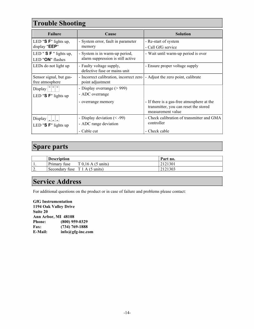
Trouble Shooting Failure Cause Solution
LED "S F" lights up, display "EEP"
- System error, fault in parameter memory
- Re-start of system - Call GfG service
LED " S F " lights up, LED "ON" flashes
- System is in warm-up period, alarm suppression is still active
- Wait until warm-up period is over
LEDs do not light up - Faulty voltage supply, defective fuse or mains unit
- Ensure proper voltage supply
Sensor signal, but gas-free atmosphere
- Incorrect calibration, incorrect zero point adjustment
- Adjust the zero point, calibrate
DisplayLED "S F" lights up
- Display overrange (> 999) - ADC overrange
- overrange memory - If there is a gas-free atmosphere at the transmitter, you can reset the stored measurement value
DisplayLED "S F" lights up
- Display deviation (< -99) - ADC range deviation
- Check calibration of transmitter and GMA controller
- Cable cut - Check cable
Spare parts Description Part no. 1. Primary fuse T 0,16 A (5 units) 2121301 2. Secondary fuse T 1 A (5 units) 2121303
Service Address For additional questions on the product or in case of failure and problems please contact:
GfG Instrumentation 1194 Oak Valley Drive Suite 20 Ann Arbor, MI 48108 Phone: (800) 959-0329 Fax: (734) 769-1888 E-Mail: [email protected]

-15-
GMA 84 - Gas List GasNr.
Gas Chemical Formula
GMANr
GasNr.
Gas Chemical Formula
GMANr
1 Aceton CH6O 1 55 Carbon dioxide CO2 CO22 Acetonnitrile C2H3N 2 56 Carbon monoxide CO CO3 Acetylene C2H2 3 57 Coke gas CO, CH4, H2 57 4 Acrylnitrile C3H3N 4 58 Air N2, O2, CO2 58 5 Aminopropane C3H9N 5 59 Methane CH4 CH46 Ammonia NH3 nh3 60 Methanol CH4O 60 7 Amyl alcohol C5H12O 7 61 Methyl acetate C3H6O2 61 8 Benzine 60/95 Mixture 8 62 Methyl alcohol CH3OH 62 9 Benzine 80/110 Mixture 9 63 Methylbutylketone C6H12O 63
10 Benzine (fuel) Mixture 10 64 Methyl chloride CH3Cl 64 11 Benzene C6H6 11 65 Methylene chloride CH2Cl2 65 12 Comb. gases and vapours Mixture 12 66 Methyl-i-butylketone C6H12O 66 13 Bromtrifluoromethane (Halon) C Br F3 13 67 Methylethylketone C4H8O 67 14 Butadien - 1.3 C4H6 14 68 Methylglycol C3H8O2 68 15 n-Butane C4H10 but. 69 Methylmethacrylate C5H8O2 69 16 i-Butane (CH3)3CH 16 70 Methylpropanol C4H10O 70 17 Butanol - 1 C4H10O 17 71 Monochlordifluormonobrom. C Br Cl F2 71 18 Butanon - 2 C4H8O 18 72 n-Nonane C9H20 non.19 n-Butylacetate C6H12O2 19 73 i-Octane C8H18 73 20 i-Butylacetate C6H12O2 20 74 n-Octane C8H18 74 21 n-Butyl alcohol C4H10O 21 75 i-Pentane C5H12 75 22 1-Butylene C4H8 22 76 n-Pentane C5H12 76 23 Chlorine Cl2 CL2 77 Pentanon-2 C5H10O 77 24 Chloromethane CH3Cl 24 78 Penten-1 C5H10 78 25 Hydrogen chloride HCl HCL 79 Pentyl acetate C7H14O2 79 26 Hydrogen cyanide HCN hcn 80 Perchloroethylene C2Cl4 80 27 Cyclohexane C6H12 27 81 Propane C3H8 Pro.28 Cyclopentan C5H10 28 82 Propanol-2 C3H8O 82 29 Cyclopropane C3H6 29 83 i-Propyl acetate C5H10O2 83 30 Dichlordifluoromethane (R12) C Cl2 F2 30 84 n-Propyl acetate C5H10O2 84 31 1.1 Dichlorethane C2H4Cl2 31 85 n-Propyl alcohol C3H8O 85 32 Dichlorfluoromethane (R21) CH Cl2F 32 86 i-Propyl alcohol C3H8O 86 33 Dichloromethaen CH2Cl2 33 87 Propylene C3H6 87 34 1.2 Dichloropropane C3H6Cl2 34 88 Propylenedichloride-1.2 C3H6Cl2 88 35 Diethylamine C4H11N 35 89 Oxygen O2 O236 Dimethylether C2H6O 36 90 Sulfur dioxide SO2 SO237 Epichlorhydrin C3H5Cl O 37 91 Sulfurhexafluoride SF6 91 38 Natural gas (H+L) Cn Hm, N2 38 92 Hydrogen sulfide H2S H2S39 Ethane C2H6 39 93 Town gas CO, CH4, H2 93 40 Ethanol C2H5OH Eol. 94 Nitrogen dioxide NO2 no241 Ethyl acetate C4H8O2 41 95 Nitrogen monoxide NO no42 Ethyl alcohol C2H6O 42 96 Styrene C8H8 96 43 Ethylen C2H4 43 97 Tetrachloroethane C2Cl4 97 44 Ethylen oxide C2H4O 44 98 Toluene C7H8 98 45 FAM-Benzine Mixture 45 99 1.1.1-Trichloroethane C2H3Cl3 99 46 Jet fuel 40/180 Mixture 46 100 Trichloroethylene C2HCl3 100 47 Formaldehyde CH2O 47 101 Trifluoromethane (R23) CH F3 101 48 Frigen 22 CH Cl F2 r22 102 Vinyl acetate C4H6O2 102 49 Helium He 49 103 Vinyl chloride C2H3Cl 103 50 Heptane C7H16 50 104 Hydrogen H2 H251 n-Hexane C6H14 51 105 Water gas H2, CO, CH4 105 52 i-Hexane C6H14 52 106 Xylene C8H10 106 53 Hexanon-2 C6H12O 53 107 Ozone O3 107 54 Isobutyl acetate C6H12O2 54
Chart 1 - GfG-Gas List

-16-
Terminal Diagram - GMA 84 GMA 84 – Assembly Plan
Terminal for light and buzzer, for model GMA 84A.
Attention! - NO voltage-free contacts - only for connecting of GMA 84A light and
buzzer DO NOT connect any other alarm devices!
Terminal bars GMA 84 / GMA 84A
Terminal bar GMA 84 / GMA 84A
111
1 2 3 4 5 6 7 8 9 10 11 12 16 17 18 19 20 21 22 23 24 25 26 27 28 29 30
Voltage supply
Voltage supply Terminal 230 V AC L1 1Neutral N 2Protection PE 3
Alarm relays
Terminal Alarm 1 Alarm 2 Alarm 3 Fault
4 7 10 166 9 12 18
5 8 11 17
Transmitter
Terminal Transmitter 1 Transmitter 2 Transmitter 3 Transmitter 4
Voltage supply 24 V DC 19 22 25 28
Ground 20 23 26 29 Signal input 0.2 .. 1 mA or 4 .. 20 mA 21 24 27 30

-17-
Technical DataGas warning system GMA 84 for wall mounting
Type: GMA 84 Dimensions: 256 x 216 x 123 mm (WxHxD)
Gas warning system GMA 84 A incl. Alarm buzzer and lamp, for wall mounting Type: GMA 84A
Dimensions: 256 x 254 x 123 mm (WxHxD)
Power supplyOperational voltage: 230 V / 50Hz Power consumption: max 30 W at 230 V AC
Primary fuse: 0.16 A Secondary fuse: 1 A
Transmitter: 0.5 A
Climate conditionsfor operation: -10 to +55 °C, 0 to 99 % r.h., 700 to 1300 hPa
recommended storage conditions for GMA, accessories, spares: -25 to +50 °C, 0 to 99 % r.h.
Transmitter connectionTransmitter:
Transmitter connection: Voltage supply output:
Input signals:
4 Transmitter of the same kind and detection range 2-, 3-wire 18 to 24 V DC 4 .. 20 mA, 0.2 .. 1 mA
OutputsDisplay Transmittersignal: 0.2 .. 1 mA max. Deviation: 0.2 .. 0.5 mA ±0.02 mA
>0.5 mA ± 0.05 mA 4 .. 20 mA max. Deviation: 4 .. 20 mA ± 0.4 mA >10 mA + 1 mA
Relays: max. switching voltage 250 V AC 50/60 Hz or 30 V DC max. switching current 10 A AC/DC max. switching performance 2500 VA AC or 300 W DC Relay outputs and mains supply are operation insulated
SafetyProtection: DIN 40050 - IP –54
Protective separation: By means of safety transformer type: UI 39/21 PRI 230 V / SEC 30 V 50 .. 60 Hz
Protective insulation: as per EN 61010 up to over voltage category III and soiling degree 2 Certificate of manufacturer: The GMA 84 complies to the guidelines of EMC – regulation 89/336/EWG and
the low voltage regulation 73/23EWG

-18-
Annex
Terminal Diagramm of Transmitter
Transmitter CC 0238 EX (Type MWG 0238 EX)The CC sensor is designed as 3-wire transmitter. The supply voltage and the 0.2 - 1 mA output signal use the same ground line. Cable type: e.g. LiYCY 3 x 0.75 mm² (up to 200 m).
For connection of transmitters 2 to 4 repeat the steps for transmitter 1 (see picture below).
0238(EX)
2 0 3 31 30 32
Sensor
M U S
to sensor
Shield
Shielding of cable is done over the EMC cable screwing
GMA 84 Terminals
19 20 21 22 23 24 25 26 27 28 29 30
(M) Ground(U): Supply 24V DC
(S) Signal: 0.2 ... 1.0mA
MWG 1 MWG 2 MWG 3 MWG 4

-19-
Transmitter CS21 and CI21These sensors are designed as 3-wire transmitters.
0.2 – 1 mA The supply voltage and the 0.2 – 1 mA output signal use the same ground line.
Cable type: e.g. LiYCY 3 x 0.75 mm² (up to 200m)
For connection of transmitters 2 to 4 repeat the steps for transmitter 1 (see picture below).
GMA84 Terminals
(M) Ground(U) Supply: 24V DC
(S) Signal: 0,2 ... 1,0mA Shielding of cable is done over the EMC cable screwing
Sensor
CS 21 CI 21
56 4
M U S
21 3
to the SensorShield
19 20 21 22 23 24 25 26 27 28 29 30
MWG 1 MWG 2 MWG 3 MWG 4
4 – 20 mA output signal The supply voltage and the 4 – 20 mA output signal use the same ground line.
For connection of transmitters 2 to 4 repeat the steps for transmitter 1 (see picture below).
GMA84 Terminals
(M) Ground(U) Supply: 24V DC
(S) Signal: 4 ... 20 mA Shielding of cable is done over the EMC cable screwing
Sensor
CS 21 CI 21
56 4
M U S
21 3
to the SensorShield
19 20 21 22 23 24 25 26 27 28 29 30
MWG 1 MWG 2 MWG 3 MWG 4

-20-
Transmitter EC24 (models MWG 2412, 2414, 2411 and 2413)
4 – 20 mA output signalThe EC models MWG 2412 and MWG 2414 are designed as 2-wire transmitters. The 4 - 20mA output signal is provided via the supply line.
For connection of transmitters 2 to 4 repeat the steps for transmitter 1 (see picture below).
GMA84 Terminal
(M) Ground(U) Supply: 24V DC
(S) Signal: 4 ... 20mA
MWG 2412
56 4
Sensor
M U (S)
MWG 2414
Shield
Shielding is done by means of a EMC cable screwing
19 20 21 22 23 24 25 26 27 28 29 30
MWG 1 MWG 2 MWG 3 MWG 4
0.2 – 1 mA output signal The EC models MWG 2411 and MWG 2413 are designed as 3-wire transmitters. The supply voltage and the 0.2 - 1mA output signal use the same ground line.
For connection of transmitters 2 to 4 repeat the steps for transmitter 1 (see picture below).
GMA84 Terminal
(M) Ground(U) Supply: 24V DC
(S) Signal: 0,2 ... 1,0mA
MWG 2411
56 4
Sensor
M U
MWG 2413
S Shielding is done by means of a EMC cable screwing
Shield
19 20 21 22 23 24 25 26 27 28 29 30
MWG 1 MWG 2 MWG 3 MWG 4

-21-
Transmitter CC 24 EX (models MWG 2431 and MWG 2432),Transmitter CS 24 EX (models MWG 2471 and MWG 2472)
0.2 – 1 mA output signal The CC sensor MWG 2431, the CS sensor MWG 2471 are designed as 3-wire transmitters. The supply voltage and the 0.2 - 1mA output signal use the same ground line.
For connection of transmitters 2 to 4 repeat the steps for transmitter 1 (see picture below).
MWG 2431 MWG 2471
21 3 4 5 6
Sensor
MU S
to sensor Shield
Shielding of cable is done over the EMC cable screwing
GMA44 Terminals
19 20 21 22 23 24 25 26 27
(M) Ground (U) Supply: 24 V DC
(S) Signal: 0,2 ... 1,0mA
28 29 30 31 32 33 34 35 36
MWG 1 MWG 2 MWG 3 MWG 4
4 – 20 mA output signalThe CC sensor MWG 2432, the CS sensor MWG 2472 are designed as 3-wire transmitters. The supply voltage and the 4 - 20mA output signal use the same ground line.
For connection of transmitters 2 to 4 repeat the steps for transmitter 1 (see picture below).
MWG 2432 MWG 2472
21 3 4 5 6
Sensor
MU S
to sensor Shield
GMA44 Terminals
19 20 21 22 23 24 25 26 27
(M) Ground(U) Supply: 24 V DC
(S) Signal: 4 ... 20mA
28 29 30 31 32 33 34 35 36
MWG 1 MWG 2 MWG 3 MWG 4
Shielding of cable is done over the EMC cable screwing
GMA 84 Terminals
GMA 84 Terminals

-22-
Transmitter IR 24 (Type MWG 2491 and type MWG 2492)
0.2 – 1 mA output signal The IR sensor MWG 2491 is designed as 3-wire transmitters.
The supply voltage and the 0.2 - 1mA output signal use the same ground line.
For connection of transmitters 2 to 4 repeat the steps for transmitter 1 (see picture below).
Abschirmung des Kabelserfolgt über die EMV-Kabelverschraubung
MWG 2491
Sensor
MU
S
456
GMA44 Anschlussklemmen
19 20 21 22 23 24 25 26 27
(M) Masse (U) Versorgung: 24 V DC
(S) Signal: 0,2 ... 1,0mA
28 29 30 31 32 33 34 35 36
MWG 1 MWG 2 MWG 3 MWG 4
Schirm
4 – 20 mA output signalThe IR sensor 2492 is designed as 3-wire transmitters. The supply voltage and the 4 - 20mA output signal use the same ground line.
For connection of transmitters 2 to 4 repeat the steps for transmitter 1 (see picture below).
Shielding of cable isdone via the EMC
cable screwing
MWG 2492
Sensor
MU
S
456
GMA44 Anschlussklemmen
19 20 21 22 23 24 25 26 27
(M) Masse (U) Versorgung: 24 V DC
(S) Signal: 4 ... 20 mA
28 29 30 31 32 33 34 35 36
MWG 1 MWG 2 MWG 3 MWG 4
Schirm
Shielding of cable is done by means of the EMC cable screwing
GMA 84 Terminals (U) supply: 24 V DC
(M) load (S) signal: 0,2..1,0 mA
Shielding
GMA 84 Terminals
(U) supply: 24 V DC (M) load (S) signal: 4 .. 20 mA
Shielding

-23-
Transmitter EC25 (models MWG 2502, 2504, 2501 and 2503) without Ex-barrier
4 – 20 mA output signal The EC sensors MWG 2502 and MWG 2504 are designed as 2-wire transmitters. The 4 - 20mA output signal is provided via the supply line.
For connection of transmitters 2 to 4 repeat the steps for transmitter 1 (see picture below).
21
34
Sensor
12-24V
+Sig.- Sig.
MWG 2502 MWG 2504
+/- 0V
Shield
Shielding of cable is done over the EMC cable screwing
GMA84 Terminals
19 20 21 22 23 24 25 26 27 28 29 30
(U) Supply: 24 V DC
(S) Signal: 4 ... 20mA
MWG 1 MWG 2 MWG 3 MWG 4
0.2 – 1mA output signalThe EC sensors MWG 2501 and MWG 2503 are designed as 3-wire transmitters. The supply voltage and the 0.2 - 1mA output signal use the same ground line.
For connection of transmitters 2 to 4 repeat the steps for transmitter 1 (see picture below).
21
34
Sensor
12-24V
+Sig.- Sig.
MWG 2501 MWG 2503
+/- 0V
Shield
Shielding of cable is done over the EMC cable screwing
GMA84 Terminals
19 20 21 22 23 24 25 26 27 28 29 30
(M) Ground (U) Supply: 24 V DC
(S) Signal: 0.2 ... 1.0mA
MWG 1 MWG 2 MWG 3 MWG 4

-24-
Transmitter EC25 EX (model MWG 2501) with Ex-barrier
0.2 – 1 mA output signal The EC sensor MWG 2501 is designed as 4-wire transmitter. Supply and signal lines are separated. The transmitter is considered as 4-pole. For reasons of explosion protection, Ex-barriers are linked between transmitter and GMA 84 both in the supply lines and in the signal lines. For connection of transmitters 2 to 4 repeat the steps for transmitter 1 (see picture below).
21
34
Sensor
+/- 0V12-24V
+ Sig.- Sig.
MWG 2501
ib+
ib -
PA
Un+
Un - Potential
compensation
Supply barrierib+
ib -
PA
Un+
Un -
Evaluation barrier
Shielding of cable is done over the EMC cable screwing
Shield
GMA84 terminals
19 20 21 22 23 24 25 26 27 28 29 30
(M) Ground (U) Supply: 24 V DC
(S) Signal: 0.2 ... 1.0mA
MWG 1 MWG 2 MWG 3 MWG 4

GfG Instrumentation, Inc.1194 Oak Valley Dr.Suite 20Ann Arbor, MI 48108USA
US/Canada: (800) 959-0329US/Canada Fax: (734) 769-1888International: +1 734 769 0573International Fax: +1 734 769 1888Website: www.gfg-inc.com
Worldwide Manufacturer of Gas Detection Solutions7004-GM84 Rev. 2Software Version 2.02