fixtures, lighting; and associated parts;...
TRANSCRIPT

Comments, suggestions, or questions on this document should be addressed to Commander, Naval Sea Systems Command, ATTN: SEA 05S, 1333 Isaac Hull Avenue, SE, Stop 5160, Washington Navy Yard, DC 20376-5160 or emailed to CommandStandards@navy mil, with the subject line “Document Comment”. Since contact informationcan change, you may want to verify the currency of this address information using the ASSIST Online database at https://assist.dla.mil.
AMSC N/A FSC 6210
INCH-POUND MIL-DTL-16377J(SH) 30 June 2014 SUPERSEDING MIL-DTL-16377H(SH) 02 August 1996
DETAIL SPECIFICATION FIXTURES, LIGHTING; AND ASSOCIATED PARTS; SHIPBOARD USE, GENERAL SPECIFICATION FOR
Downloaded from http://www.everyspec.com

MIL-DTL-16377J(SH)
ii
Downloaded from http://www.everyspec.com

MIL-DTL-16377J(SH)
iii
CONTENTS
PARAGRAPH PAGE 1. SCOPE ...................................................................................................................................................................... 1
1.1 Scope. ................................................................................................................................................................. 1 1.2 Classification. .................................................................................................................................................... 1
1.2.1 Types. ......................................................................................................................................................... 1 1.2.2 Classes. ....................................................................................................................................................... 1
2. APPLICABLE DOCUMENTS ................................................................................................................................ 1 2.1 General. .............................................................................................................................................................. 1 2.2 Government documents. .................................................................................................................................... 1
2.2.1 Specifications, standards, and handbooks. ................................................................................................. 1 2.2.2 Other Government documents, drawings, and publications. ...................................................................... 2
2.3 Non-Government publications. .......................................................................................................................... 3 2.4 Order of precedence. .......................................................................................................................................... 4
3. REQUIREMENTS ................................................................................................................................................... 4 3.1 Specification sheets. ........................................................................................................................................... 4 3.2 First article. ........................................................................................................................................................ 4 3.3 Type III replacements for type I and type II fixtures. ........................................................................................ 4 3.4 Materials. ........................................................................................................................................................... 5
3.4.1 General requirements. ................................................................................................................................ 5 3.4.1.1 Specific materials. .............................................................................................................................. 5 3.4.1.2 Substitute materials. ........................................................................................................................... 5 3.4.1.3 Material not specified. ........................................................................................................................ 5 3.4.1.4 Recycled, recovered, environmentally preferable, or biobased materials. ......................................... 5
3.4.2 Prohibited materials. .................................................................................................................................. 5 3.4.2.1 Flammable plastic materials. .............................................................................................................. 5
3.4.3 Fungus-inert materials. ............................................................................................................................... 5 3.4.4 Arc-resistant materials. .............................................................................................................................. 5 3.4.5 Metals. ........................................................................................................................................................ 5
3.4.5.1 Selection of metals in direct contact. .................................................................................................. 6 3.4.5.2 Corrosion-resistant. ............................................................................................................................ 6 3.4.5.3 Aluminum. .......................................................................................................................................... 6 3.4.5.4 Nonferrous material. ........................................................................................................................... 6
3.4.6 Plastics. ...................................................................................................................................................... 6 3.4.6.1 Uniformity. ......................................................................................................................................... 6 3.4.6.2 Mechanical parts. ................................................................................................................................ 6 3.4.6.3 Thermoplastic materials. .................................................................................................................... 6 3.4.6.4 Electrical insulating parts. .................................................................................................................. 6
3.4.6.4.1 Plastics, laminated. ..................................................................................................................... 6 3.4.6.4.2 Thermosetting, molded. .............................................................................................................. 6
3.4.7 Springs. ...................................................................................................................................................... 6 3.4.8 Magnetic permeability. .............................................................................................................................. 6
3.5 Parts and features – mechanical. ........................................................................................................................ 7 3.5.1 Hardware. ................................................................................................................................................... 7 3.5.2 Dimensions and tolerances. ........................................................................................................................ 7 3.5.3 Assembly fabrication. ................................................................................................................................ 7 3.5.4 Drilling, countersinking, and tapping. ........................................................................................................ 7 3.5.5 Sharp edges. ............................................................................................................................................... 7 3.5.6 Castings and molded parts.......................................................................................................................... 7 3.5.7 Surface textures. ......................................................................................................................................... 7 3.5.8 Threaded parts and devices. ....................................................................................................................... 7
3.5.8.1 Threads. .............................................................................................................................................. 7 3.5.8.2 Engagement of threaded parts. ........................................................................................................... 7 3.5.8.3 Thread cutting screws. ........................................................................................................................ 7 3.5.8.4 Threads in plastics. ............................................................................................................................. 7
Downloaded from http://www.everyspec.com

MIL-DTL-16377J(SH)
iv
PARAGRAPH PAGE 3.5.8.5 Threads in aluminum. ......................................................................................................................... 8 3.5.8.6 Anti-seizure coating. .......................................................................................................................... 8 3.5.8.7 Threads locking. ................................................................................................................................. 8
3.5.9 Seals and special screws. ............................................................................................................................ 8 3.5.10 Gaskets. .................................................................................................................................................... 8
3.5.10.1 Window gaskets for type I, class 2 fixtures and type III luminaires using legacy fluorescent windows. ......................................................................................................................................................... 8 3.5.10.2 O-ring gaskets................................................................................................................................... 8 3.5.10.3 U-shaped gaskets. ............................................................................................................................. 8 3.5.10.4 Gasket coating. ................................................................................................................................. 8 3.5.10.5 Window gaskets for type III luminaires. .......................................................................................... 8
3.5.11 Enclosures. ............................................................................................................................................... 9 3.5.11.1 Enclosures, type I, class 1. ................................................................................................................ 9 3.5.11.2 Enclosures, type I, class 2. ................................................................................................................ 9 3.5.11.3 Enclosures, type II, classes 1 and 2. ................................................................................................. 9 3.5.11.4 Enclosures, type III. .......................................................................................................................... 9
3.5.11.4.1 Additional class 2 requirements. ............................................................................................... 9 3.5.11.5 Parts. ................................................................................................................................................. 9 3.5.11.6 Drainage. .......................................................................................................................................... 9 3.5.11.7 Gasket groove. .................................................................................................................................. 9
3.5.12 Shock. ....................................................................................................................................................... 9 3.5.12.1 Types I, II, and III, class 1 fixtures. .................................................................................................. 9 3.5.12.2 Types I, II, and III, class 2 fixtures. .................................................................................................. 9 3.5.12.3 Parts. ............................................................................................................................................... 10
3.5.13 Vibration. ............................................................................................................................................... 10 3.5.14 Noise. ..................................................................................................................................................... 10 3.5.15 Salt spray. ............................................................................................................................................... 10 3.5.16 Shock mounts. ........................................................................................................................................ 10 3.5.17 Ambient temperature. ............................................................................................................................. 10
3.6 Parts and features – electrical........................................................................................................................... 10 3.6.1 Safety. ...................................................................................................................................................... 10 3.6.2 Lamps. ...................................................................................................................................................... 10 3.6.3 Lamplocks for type I fixtures. .................................................................................................................. 10 3.6.4 Lampholders. ............................................................................................................................................ 10
3.6.4.1 Lampholder spacing for type I fixtures and lights. ........................................................................... 10 3.6.4.2 Insulating spacer for type II fixtures and lights. ............................................................................... 10 3.6.4.3 Counterbored holes. .......................................................................................................................... 10
3.6.5 Starter sockets for type I fixtures and lights. ............................................................................................ 11 3.6.6 Starters for type I fixtures and lights. ....................................................................................................... 11 3.6.7 Starter washers for type I fixtures and lights. ........................................................................................... 11 3.6.8 Ballasts for type I fixtures and lights. ....................................................................................................... 11
3.6.8.1 Mounting. ......................................................................................................................................... 11 3.6.9 Terminal board. ........................................................................................................................................ 11
3.6.9.1 Mounting. ......................................................................................................................................... 11 3.6.10 Switches. ................................................................................................................................................ 11
3.6.10.1 Toggle switches. ............................................................................................................................. 12 3.6.10.2 Push-button switches. ..................................................................................................................... 12 3.6.10.3 Boots............................................................................................................................................... 12
3.6.11 Wiring. ................................................................................................................................................... 12 3.6.11.1 Electrical connections for type III luminaires................................................................................. 12 3.6.11.2 Hook-up wires. ............................................................................................................................... 12 3.6.11.3 Harnessing. ..................................................................................................................................... 12 3.6.11.4 Insulation protection. ...................................................................................................................... 12
3.6.12 Cable and cable entrances. ..................................................................................................................... 12 3.6.13 Ground potential and grounding. ........................................................................................................... 12
Downloaded from http://www.everyspec.com

MIL-DTL-16377J(SH)
v
PARAGRAPH PAGE 3.6.13.1 Electrical circuits. ........................................................................................................................... 12 3.6.13.2 Exposed metal (or other conductive) parts. .................................................................................... 12 3.6.13.3 Ground connection. ........................................................................................................................ 13 3.6.13.4 Continuity of grounding. ................................................................................................................ 13 3.6.13.5 Portable fixtures. ............................................................................................................................ 13
3.6.14 Electromagnetic interference (type I and type III only). ........................................................................ 13 3.6.15 Dielectric withstanding voltage. ............................................................................................................. 13 3.6.16 Insulating resistance. .............................................................................................................................. 13 3.6.17 Fail-safe circuit design for type III luminaires. ...................................................................................... 13 3.6.18 Power interface requirements. ................................................................................................................ 13
3.6.18.1 Total harmonic distortion for type I and type III fixtures. .............................................................. 13 3.6.18.2 Voltage transient spike for type I and type III fixtures. .................................................................. 13
3.6.19 Class 2 emergency light fixtures. ........................................................................................................... 13 3.6.19.1 Class 2 emergency light fixture output life. .................................................................................... 13 3.6.19.2 Class 2 emergency light fixture battery. ......................................................................................... 13 3.6.19.3 Class 2 emergency light fixture charging system. .......................................................................... 13
3.7 Light output and associated hardware. ............................................................................................................. 14 3.7.1 Candlepower distribution for fixtures. ..................................................................................................... 14
3.7.1.1 Lumen output for emergency class 2 lighting. ................................................................................. 14 3.7.2 Footcandle distribution for fixtures. ......................................................................................................... 14 3.7.3 Color (chromaticity) and luminous transmittance for parts. ..................................................................... 14
3.7.3.1 Red transparent. ................................................................................................................................ 14 3.7.3.2 Yellow transparent. .......................................................................................................................... 14 3.7.3.3 Green transparent. ............................................................................................................................ 14 3.7.3.4 Blue transparent. ............................................................................................................................... 14 3.7.3.5 White translucent. ............................................................................................................................. 14 3.7.3.6 Red translucent. ................................................................................................................................ 15 3.7.3.7 Clear (colorless) transparent. ............................................................................................................ 15
3.7.4 Chromaticity for type III luminaires. ....................................................................................................... 15 3.7.4.1 White light. ....................................................................................................................................... 15
3.7.4.1.1 Correlated color temperature (CCT). ........................................................................................ 15 3.7.4.1.2 Color rendering index (CRI). .................................................................................................... 15
3.7.4.2 Red light. .......................................................................................................................................... 15 3.7.4.3 Amber (yellow) light. ....................................................................................................................... 15 3.7.4.4 Blue light. ......................................................................................................................................... 15 3.7.4.5 Night vision device (NVD) friendly cyan light. ............................................................................... 16
3.7.4.5.1 Night vision radiant intensity. ................................................................................................... 16 3.7.5 Brightness for type III luminaires. ........................................................................................................... 16
3.7.5.1 Brightness at nadir. ........................................................................................................................... 16 3.7.5.2 Brightness at angle. .......................................................................................................................... 16 3.7.5.3 Local brightness. .............................................................................................................................. 16
3.7.6 Windows and window assemblies. ........................................................................................................... 16 3.7.6.1 Windows and window assemblies for type I fixtures. ...................................................................... 16
3.7.6.1.1 Material for windows. ............................................................................................................... 16 3.7.6.1.1.1 Optical uniformity. ............................................................................................................ 16 3.7.6.1.1.2 Corners. ............................................................................................................................. 16
3.7.6.1.2 Louver assembly. ...................................................................................................................... 16 3.7.6.1.2.1 Material. ............................................................................................................................ 16 3.7.6.1.2.2 Attachment to window. ..................................................................................................... 16 3.7.6.1.2.3 Louver grounding.............................................................................................................. 16
3.7.6.1.3 Window securing screw assemblies. ........................................................................................ 17 3.7.6.1.4 Notches. .................................................................................................................................... 17
3.7.6.2 Windows and window assemblies for type III luminaires. ............................................................... 17 3.7.6.2.1 Material for windows. ............................................................................................................... 17
3.7.6.2.1.1 Optical uniformity. ............................................................................................................ 17
Downloaded from http://www.everyspec.com

MIL-DTL-16377J(SH)
vi
PARAGRAPH PAGE 3.7.6.2.2 Louver assembly. ...................................................................................................................... 17
3.7.6.2.2.1 Material. ............................................................................................................................ 17 3.7.6.2.2.2 Attachment to window. ..................................................................................................... 17 3.7.6.2.2.3 Louver grounding.............................................................................................................. 17
3.7.7 Lenses, globes, roundels, and windows for type II fixtures. .................................................................... 17 3.7.7.1 Optical uniformity. ........................................................................................................................... 17 3.7.7.2 Material. ........................................................................................................................................... 17 3.7.7.3 Edges. ............................................................................................................................................... 17 3.7.7.4 Colored glassware. ........................................................................................................................... 17 3.7.7.5 Painted glassware. ............................................................................................................................ 17 3.7.7.6 Mechanical shock. ............................................................................................................................ 18 3.7.7.7 Thermal shock. ................................................................................................................................. 18 3.7.7.8 External hydrostatic pressure. .......................................................................................................... 18 3.7.7.9 Breakage pattern. .............................................................................................................................. 18
3.7.8 Reflectors. ................................................................................................................................................ 18 3.7.9 Filters. ...................................................................................................................................................... 18
3.7.9.1 Red filter tubes for type I, class 2 fixtures. ....................................................................................... 18 3.7.9.1.1 All red fixture(s). ...................................................................................................................... 18 3.7.9.1.2 Single red with white fixture(s). ............................................................................................... 18 3.7.9.1.3 Two red with white fixture(s). .................................................................................................. 18 3.7.9.1.4 Red directional fixture(s). ......................................................................................................... 18
3.7.9.2 Blue filter tubes for type I fixtures. .................................................................................................. 18 3.7.9.3 Gray filter tubes for type I fixtures. .................................................................................................. 18 3.7.9.4 Night vision friendly filter tubes for type I fixtures.......................................................................... 18 3.7.9.5 Amber filter tubes for type I fixtures. ............................................................................................... 18
3.7.10 Type III lens color. ................................................................................................................................. 18 3.7.11 Lumen maintenance for type III luminaires. .......................................................................................... 19
3.7.11.1 Lumen maintenance, ambient (1,000 hours at 77 °F [25 °C]). ....................................................... 19 3.7.11.2 Lumen maintenance, accelerated (1,000 hours at 122 °F [50 °C]). ................................................ 19
3.8 Processes. ......................................................................................................................................................... 19 3.8.1 Treatment and processing of metals for corrosion-resistance. ................................................................. 19 3.8.2 Painting. ................................................................................................................................................... 19 3.8.3 Finishing for fixtures and parts. ............................................................................................................... 19
3.8.3.1 Cleaning. .......................................................................................................................................... 19 3.8.3.2 Surface preparation. .......................................................................................................................... 19 3.8.3.3 Finish. ............................................................................................................................................... 19 3.8.3.4 Types I, II, and type III, class 1 fixtures. .......................................................................................... 19 3.8.3.5 Types I, II, and type III, class 2 fixtures. .......................................................................................... 19 3.8.3.6 Parts. ................................................................................................................................................. 20
3.8.4 Finishing for windows and window assemblies for type I fixtures. ......................................................... 20 3.8.4.1 Windows. .......................................................................................................................................... 20 3.8.4.2 Louver assemblies. ........................................................................................................................... 20 3.8.4.3 Antistatic coating. ............................................................................................................................. 20
3.8.5 Stress relief. .............................................................................................................................................. 20 3.8.5.1 Stress-corrosion cracking of metals. ................................................................................................. 20 3.8.5.2 Plastics. ............................................................................................................................................. 20 3.8.5.3 Plastic windows for type I fixtures. .................................................................................................. 20
3.8.6 Welding. ................................................................................................................................................... 20 3.9 Designation and marking. ................................................................................................................................ 20
3.9.1 Labels. ...................................................................................................................................................... 20 3.9.1.1 Material. ........................................................................................................................................... 20 3.9.1.2 Adhesive. .......................................................................................................................................... 21
3.9.1.2.1 Adhesion. .................................................................................................................................. 21 3.9.1.3 Color. ................................................................................................................................................ 21 3.9.1.4 Thickness. ......................................................................................................................................... 21
Downloaded from http://www.everyspec.com

MIL-DTL-16377J(SH)
vii
PARAGRAPH PAGE 3.9.1.5 Size. .................................................................................................................................................. 21 3.9.1.6 Writing quality. ................................................................................................................................ 21 3.9.1.7 Marking. ........................................................................................................................................... 21 3.9.1.8 Application and classification. ......................................................................................................... 21
3.9.1.8.1 Type I labels. ............................................................................................................................ 21 3.9.1.8.2 Type II labels. ........................................................................................................................... 21 3.9.1.8.3 Type III labels. .......................................................................................................................... 21 3.9.1.8.4 Type IV labels. ......................................................................................................................... 21 3.9.1.8.5 Type V labels. ........................................................................................................................... 21 3.9.1.8.6 Type VI labels. ......................................................................................................................... 21
3.9.2 Identification and information plates. ...................................................................................................... 21 3.9.3 Identification plate (explosionproof). ....................................................................................................... 22 3.9.4 Instruction sheets or tags. ......................................................................................................................... 22
3.10 Interchangeability and standardization. ......................................................................................................... 22 3.10.1 Interchangeability. .................................................................................................................................. 22 3.10.2 Standardization. ...................................................................................................................................... 22
3.10.2.1 Component standardization. ........................................................................................................... 22 3.10.2.2 Equipment standardization. ............................................................................................................ 22 3.10.2.3 Standard stock parts (see 6.12.6). ................................................................................................... 22 3.10.2.4 Proprietary parts. ............................................................................................................................ 22
3.11 High-temperature fluorescent lighting fixtures. ............................................................................................. 22 3.11.1 Symbol numbers..................................................................................................................................... 22 3.11.2 Component substitution. ........................................................................................................................ 22
3.12 400-Hertz fluorescent lighting fixtures. ......................................................................................................... 23 3.12.1 Symbol numbers..................................................................................................................................... 23 3.12.2 Component substitution. ........................................................................................................................ 23
3.13 Workmanship. ................................................................................................................................................ 23 3.14 Energy efficiency. .......................................................................................................................................... 24 3.15 Predicted lifetime for drivers for Type III luminaires. ................................................................................... 24
4. VERIFICATION .................................................................................................................................................... 24 4.1 Classification of inspections. ........................................................................................................................... 24 4.2 Inspection conditions. ...................................................................................................................................... 24 4.3 First article inspection. ..................................................................................................................................... 24
4.3.1 Order of tests. ........................................................................................................................................... 24 4.3.2 Inspection of parts. ................................................................................................................................... 24 4.3.3 Combination of tests. ............................................................................................................................... 24
4.4 Conformance inspection. ................................................................................................................................. 24 4.4.1 Comparison inspection. ............................................................................................................................ 25 4.4.2 Inspection of product for delivery. ........................................................................................................... 25
4.4.2.1 Sampling plan for inspection of product for delivery. ...................................................................... 25 4.4.2.1.1 Lot............................................................................................................................................. 25 4.4.2.1.2 Sampling for examination and conformance tests. ................................................................... 25
4.5 Examination. .................................................................................................................................................... 25 4.5.1 Visual examination................................................................................................................................... 25 4.5.2 Examination for weight and dimensions. ................................................................................................. 26
4.6 Conformance tests. ........................................................................................................................................... 26 4.6.1 Complete fixtures or lights. ...................................................................................................................... 26 4.6.2 Plastic windows for type I fixtures and lights. ......................................................................................... 26 4.6.3 Lenses, globes, and roundels for type II fixtures and lights. .................................................................... 26
4.7 Examination for preparation of delivery. ......................................................................................................... 26 4.8 Test procedures. ............................................................................................................................................... 26
4.8.1 Operation. ................................................................................................................................................. 26 4.8.2 Dielectric withstanding voltage. ............................................................................................................... 27 4.8.3 Insulation resistance. ................................................................................................................................ 27 4.8.4 Optical uniformity test for windows, lenses, globes, and roundels. ......................................................... 27
Downloaded from http://www.everyspec.com

MIL-DTL-16377J(SH)
viii
PARAGRAPH PAGE 4.8.5 Stress relief test for plastic window for type I fixtures and lights. ........................................................... 27 4.8.6 Light output. ............................................................................................................................................. 27
4.8.6.1 Candlepower distribution. ................................................................................................................ 27 4.8.6.2 Footcandle distribution. .................................................................................................................... 27 4.8.6.3 Color and luminous transmittance. ................................................................................................... 27 4.8.6.4 Brightness test for type III luminaires. ............................................................................................. 27 4.8.6.5 Chromaticity test for type III luminaires. ......................................................................................... 27 4.8.6.6 CCT test for type III luminaires. ...................................................................................................... 27 4.8.6.7 CRI test for type III luminaires......................................................................................................... 27 4.8.6.8 Lumen output for emergency luminaires. ......................................................................................... 28
4.8.7 Shock test. ................................................................................................................................................ 28 4.8.7.1 Mounting. ......................................................................................................................................... 28
4.8.8 Vibration test. ........................................................................................................................................... 28 4.8.9 Noise test. ................................................................................................................................................. 28 4.8.10 Salt spray test. ........................................................................................................................................ 28 4.8.11 Grounding circuit. .................................................................................................................................. 28 4.8.12 Continuity of grounding. ........................................................................................................................ 28 4.8.13 Leakage current (portable fixtures only). ............................................................................................... 29 4.8.14 Enclosure effectiveness. ......................................................................................................................... 29
4.8.14.1 Totally enclosed. ............................................................................................................................ 29 4.8.14.2 Dripproof. ....................................................................................................................................... 29 4.8.14.3 Splashproof. .................................................................................................................................... 29 4.8.14.4 Watertight and submersible. ........................................................................................................... 29 4.8.14.5 Explosionproof. .............................................................................................................................. 29 4.8.14.6 Combined explosionproof-watertight. ............................................................................................ 29
4.8.15 Explosionproof tests. .............................................................................................................................. 29 4.8.15.1 Explosion test. ................................................................................................................................ 29 4.8.15.2 Hydrostatic pressure test................................................................................................................. 29
4.8.16 Electromagnetic interference (type I and type III only). ........................................................................ 29 4.8.17 Tests for glassware. ................................................................................................................................ 29
4.8.17.1 Color determination test. ................................................................................................................ 29 4.8.17.2 Paint removal test. .......................................................................................................................... 29 4.8.17.3 Mechanical shock test. .................................................................................................................... 29 4.8.17.4 Thermal shock test. ......................................................................................................................... 30 4.8.17.5 External hydrostatic pressure test. .................................................................................................. 30 4.8.17.6 Breakage pattern test. ..................................................................................................................... 30
4.8.18 Magnetic permeability. .......................................................................................................................... 30 4.8.19 Ambient temperature. ............................................................................................................................. 30 4.8.20 Lumen maintenance test for type III luminaires. .................................................................................... 30
4.8.20.1 Lumen maintenance, ambient (1,000 hours at 77 °F [25 °C]) test. ................................................ 30 4.8.20.2 Lumen maintenance, accelerated (1,000 hours at 122 °F [50 °C]) test. ......................................... 30 4.8.20.3 Lumen maintenance photometric test. ............................................................................................ 30
4.8.21 Power interface test. ............................................................................................................................... 30 4.8.22 Power quality test. .................................................................................................................................. 31 4.8.23 Voltage transient spike test. ................................................................................................................... 31 4.8.24 Fail-safe circuit design test. .................................................................................................................... 31 4.8.25 Type III chromaticity conformance inspection. ..................................................................................... 31 4.8.26 Emergency light fixture battery and charging system testing. ............................................................... 31
5. PACKAGING ......................................................................................................................................................... 31 5.1 Packaging. ........................................................................................................................................................ 31
6. NOTES ................................................................................................................................................................... 32 6.1 Intended use. .................................................................................................................................................... 32
6.1.1 Class 1 fixtures. ........................................................................................................................................ 32 6.1.2 Class 2 fixtures. ........................................................................................................................................ 32 6.1.3 Overhead standard mount fixtures. .......................................................................................................... 32
Downloaded from http://www.everyspec.com

MIL-DTL-16377J(SH)
ix
PARAGRAPH PAGE 6.1.4 Overhead flush mounted fixtures. ............................................................................................................ 32 6.1.5 Explosionproof fixtures. ........................................................................................................................... 32
6.2 Acquisition requirements. ................................................................................................................................ 32 6.3 Provisioning. .................................................................................................................................................... 33
6.3.1 Ordering of parts. ..................................................................................................................................... 33 6.4 First article inspection. ..................................................................................................................................... 33
6.4.1 Independent testing. ................................................................................................................................. 33 6.4.2 Testing details. ......................................................................................................................................... 33
6.4.2.1 Drawings acceptance. ....................................................................................................................... 33 6.4.3 Previous testing. ....................................................................................................................................... 33
6.5 Testing laboratories. ......................................................................................................................................... 33 6.6 NAVSEA. ........................................................................................................................................................ 33 6.7 Symbol number. ............................................................................................................................................... 33 6.8 Approval of the first article inspection report. ................................................................................................. 33 6.9 Comparison inspection. .................................................................................................................................... 33 6.10 Electromagnetic interference. ........................................................................................................................ 33 6.11 NAVSEA approval and direction. ................................................................................................................. 34 6.12 Definitions. .................................................................................................................................................... 34
6.12.1 Driver. .................................................................................................................................................... 34 6.12.2 Excessive corrosion. ............................................................................................................................... 34 6.12.3 Leakage current. ..................................................................................................................................... 34 6.12.4 Solid state lighting.................................................................................................................................. 34 6.12.5 Special tools. .......................................................................................................................................... 34 6.12.6 Standard stock parts. .............................................................................................................................. 34
6.13 Subject term (key word) listing. ..................................................................................................................... 34 6.14 Changes from previous issue. ........................................................................................................................ 34
APPENDIX A ............................................................................................................................................................. 55 A.1 SCOPE ................................................................................................................................................................. 55
A.1.1 Scope. ........................................................................................................................................................... 55 A.2 CERTIFICATION CONTENT ............................................................................................................................ 55
A.2.1 Certification of drawings acceptance. .......................................................................................................... 55 A.2.1.1 Drawing acceptance procedures. .......................................................................................................... 55
A.2.1.1.1 Submission of revised drawings. .................................................................................................. 55 A.2.1.1.2 Changes. ....................................................................................................................................... 55
Downloaded from http://www.everyspec.com

MIL-DTL-16377J(SH)
x
LIST OF FIGURES FIGURE PAGE 1. Securing screw assembly (long) for watertight window assemblies. ...................................................................... 35 2. Securing screw assembly (short) for watertight window assemblies. ..................................................................... 35 3. Captive bushings, securing screws, and mounting bushings. ................................................................................. 36 4. Louver attachment for watertight window assemblies. .......................................................................................... 37 5. Starter washer. ........................................................................................................................................................ 37 6. Shockmount installation for type I, class 2 fixture. ................................................................................................ 38 7. Dimensions for gasket groove and methods for retaining O-ring gasket for type I, class 2 fixtures. ..................... 39 8. Chromaticity diagram illuminant A. ....................................................................................................................... 40 9. Light transmission curves of red glassware. ........................................................................................................... 41 10. Typical styles of fluorescent lighting fixtures for general overhead lighting. ...................................................... 42 11. Type I labels. ........................................................................................................................................................ 42 12. Type II labels. ....................................................................................................................................................... 43 13. Type III labels. ...................................................................................................................................................... 43 14. Type IV labels. ..................................................................................................................................................... 43 15. Type V labels. ....................................................................................................................................................... 44 16. Type VI labels. ..................................................................................................................................................... 44 17. Standard methods of mounting lights for shock tests. .......................................................................................... 45 18. Typical ball impact equipment for shock test of glassware. ................................................................................. 46 19. Method of installing cover on type I, class 2 fixtures and lights with standard mounting. ................................... 47 20. Airborne noise acceptable levels. ......................................................................................................................... 48 21. Lampholder spacing.............................................................................................................................................. 49 22. Wiring diagram to operate one fluorescent lamp. ................................................................................................. 49 23. Wiring diagram to operate two fluorescent lamps. ............................................................................................... 50 24. Wiring diagram to operate three fluorescent lamps. ............................................................................................. 50 25. Mounting dimensions for standard mounting of fluorescent fixtures. .................................................................. 51 26. Mounting dimensions for flush mounting of fluorescent fixtures......................................................................... 52 27. Window assemblies. ............................................................................................................................................. 53 28. Mounting dimensions for incandescent fixtures. .................................................................................................. 54
LIST OF TABLES TABLE PAGE I. Flammability characteristics of plastics. ................................................................................................................... 5 II. Starters. .................................................................................................................................................................. 11 III. Component substitution for high-temperature fluorescent lighting fixtures. ........................................................ 23 IV. Sampling for examination and conformance tests. ............................................................................................... 25 V. Visual defects......................................................................................................................................................... 26
Downloaded from http://www.everyspec.com

MIL-DTL-16377J(SH)
1
This specification is approved for use by the Naval Sea Systems Command, Department of the Navy, and is available for use by all Departments and Agencies of the Department of Defense.
1. SCOPE
1.1 Scope. This specification covers fluorescent, incandescent lighting and solid state lighting (SSL) (see 6.12.4) luminaires and associated parts for legacy replacement and new luminaire development fixtures (lights) and associated parts, used for detail and general illumination on naval ships and submarines.
1.2 Classification. Lighting fixtures are of the following types and classes, as specified (see 6.2).
1.2.1 Types.
a. Type I – Fluorescent. b. Type II – Incandescent. c. Type III – Solid state.
1.2.2 Classes.
a. Class 1 – Detail illumination. b. Class 2 – General illumination.
2. APPLICABLE DOCUMENTS
2.1 General. The documents listed in this section are specified in sections 3 and 4 of this specification. This section does not include documents cited in other sections of this specification or recommended for additional information or as examples. While every effort has been made to ensure the completeness of this list, document users are cautioned that they must meet all specified requirements of documents cited in sections 3 and 4 of this specification, whether or not they are listed.
2.2 Government documents.
2.2.1 Specifications, standards, and handbooks. The following specifications, standards, and handbooks form a part of this document to the extent specified herein. Unless otherwise specified, the issues of these documents are those cited in the solicitation or contract.
FEDERAL STANDARDS
FED-STD-H28 - Screw-Thread Standards for Federal Services
FED-STD-595/16492 - Gray, Gloss (Light Gray)
FED-STD-595/17875 - Miscellaneous, Gloss (White)
FED-STD-595/17925 - Miscellaneous, Gloss (White)
FED-STD-595/26270 - Gray, Semigloss (Haze Gray)
COMMERCIAL ITEM DESCRIPTIONS
A-A-50552 - Fittings for Cable, Power, Electrical and Conduit, Metal, Flexible
A-A-59125 - Terminal Boards, Molded, Barrier Screw and Stud Types and Associated Accessories
DEPARTMENT OF DEFENSE SPECIFICATIONS
MIL-S-901 - Shock Tests, H.I. (High-Impact) Shipboard Machinery, Equipment, and Systems, Requirements for
MIL-E-917 - Electric Power Equipment Basic Requirements
Downloaded from http://www.everyspec.com

MIL-DTL-16377J(SH)
2
MIL-DTL-5423 - Boots, Dust and Moisture Seal (for Toggle and Push-Button Switches, Circuit Breakers, and Rotary-Actuated Parts), General Specification for
MIL-DTL-15024 - Plates, Tags, and Bands for Identification of Equipment, General Specification for
MIL-P-15024/5 - Plate, Identification
MIL-DTL-24191 - Plastic Sheet, Cell or Continuous Cast, Acrylic, Shipboard Application (Illumination and Signal Lighting)
MIL-DTL-24643 - Cables, Electric, Low Smoke Halogen-Free, for Shipboard Use, General Specification for
MIL-DTL-24643/3 - Cable, Electrical, -20 °C to +90 °C, 600 Volts, Types LSSHOF, LSDHOF, LSTHOF, and LSFHOF
MIL-DTL-24643/26 - Cable, Electrical, -20 °C to +150 °C, 600 Volts Types LSDPS, LSTPS, LSFPS, LS7PS, LSDPSN, LSTPSN, LSFPSN, and LS7PSN
MIL-I-24768 - Insulation, Plastics, Laminated, Thermosetting; General Specification for
MIL-I-24768/1 - Insulation, Plastic, Laminated, Thermosetting, Glass-Cloth, Melamine-Resin (GME)
(See supplement 1 for list of specification sheets.)
DEPARTMENT OF DEFENSE STANDARDS
MIL-STD-108 - Definitions of and Basic Requirements for Enclosures for Electric and Electronic Equipment
MIL-STD-167-1 - Mechanical Vibrations of Shipboard Equipment (Type I - Environmental and Type II - Internally Excited)
MIL-STD-461 - Requirements for the Control of Electromagnetic Interference Characteristics of Subsystems and Equipment
MIL-STD-810 - Environmental Engineering Considerations and Laboratory Tests
MIL-STD-1399-300 - Electric Power, Alternating Current
MIL-STD-1474 - Noise Limits
MIL-STD-3009 - Lighting, Aircraft, Night Vision Imaging System (NVIS) Compatible
DEPARTMENT OF DEFENSE HANDBOOKS
MIL-HDBK-217 - Reliability Prediction of Electronic Equipment
MIL-HDBK-454 - General Guidelines for Electronic Equipment
(Copies of these documents are available online at http://quicksearch.dla.mil.)
2.2.2 Other Government documents, drawings, and publications. The following other Government documents, drawings, and publications form a part of this document to the extent specified herein. Unless otherwise specified, the issues of these documents are those cited in the solicitation or contract.
Downloaded from http://www.everyspec.com

MIL-DTL-16377J(SH)
3
MILITARY STANDARD DRAWINGS
MS16569 - Switch, Toggle, Double Pole, Single Throw (For Use in Lighting Fixtures)
MS16656 - Switch, Toggle, Single Pole, Single Throw
(Copies of these documents are available online at http://quicksearch.dla.mil.)
2.3 Non-Government publications. The following documents form a part of this document to the extent specified herein. Unless otherwise specified, the issues of these documents are those cited in the solicitation or contract.
AMERICAN NATIONAL STANDARDS INSTITUE (ANSI)
ANSI ANSLG C78.377 - Specifications for the Chromaticity of Solid State Lighting Products
NEMA ANSI C78.180 - Specifications for Fluorescent Lamp Starters
ANSI S1.4 - American National Standard Specification for Sound Level Meters
(Copies of these documents are available online at http://webstore.ansi.org/.)
AMERICAN WELDING SOCIETY (AWS)
WHB - Welding Handbook
(Copies of this document are available online at www.aws.org.)
ASME INTERNATIONAL
ASME B46.1 - Surface Texture (Surface Roughness, Waviness, and Lay)
ASME Y14.36 - Surface Texture Symbols
(Copies of these documents are available online at www.asme.org.)
ASTM INTERNATIONAL
ASTM A342/A342M - Standard Test Methods for Permeability of Feebly Magnetic Materials
ASTM D635 - Standard Test Method for Rate of Burning and/or Extent and Time of Burning of Plastics in a Horizontal Position
ASTM D2843 - Standard Test Method for Density of Smoke from the Burning or Decomposition of Plastics
ASTM D3955 - Standard Specification for Electrical Insulating Varnishes
ASTM D4802 - Standard Specification for Poly(Methyl Methacrylate) Acrylic Plastic Sheet
ASTM D5948 - Standard Specification for Molding Compounds, Thermosetting
ASTM F1836M - Standard Specification for Stuffing Tubes, Nylon, and Packing Assemblies (Metric)
(Copies of these documents are available online at www.astm.org.)
Downloaded from http://www.everyspec.com
MIL-DTL-16377J(SH)
4
ILLUMINATING ENGINEERING SOCIETY OF NORTH AMERICA (IES)
IES LM-15 - IESNA Guide for Reporting General Lighting Equipment Engineering Data for Indoor Luminaires
IES LM-79 - Approved Method: Electrical and Photometric Measurements of Solid-State Lighting Products
IES LM-80 - Approved Method: Measuring Lumen Maintenance of LED Light Sources
IES TM-21 - Projecting Long Term Lumen Maintenance of LED Light Sources
(Copies of these documents are available online at www.ies.org.)
SAE INTERNATIONAL
SAE-AMS2175 - Castings, Classification and Inspection of
SAE-ARP4392 - Lighting, Aircraft Exterior, Night Vision Imaging System (NVIS) Compatible
SAE-ARP5825 - Design Requirements and Test Procedures for Dual Mode Exterior Lights
(Copies of these documents are available online at www.sae.org.)
UNDERWRITERS LABORATORIES INC. (UL)
UL 486A-486B - Wire Connectors
UL 496 - Lampholders
UL 844 - Standard for Luminaires for Use in Hazardous (Classified) Locations
(Copies of these documents are available online at www.comm-2000.com.)
2.4 Order of precedence. Unless otherwise noted herein or in the contract, in the event of a conflict between the text of this document and the references cited herein (except for related specification sheets), the text of this document takes precedence. Nothing in this document, however, supersedes applicable laws and regulations unless a specific exemption has been obtained.
3. REQUIREMENTS
3.1 Specification sheets. The individual item requirements shall be as specified herein and in accordance with the applicable specification sheet. In the event of any conflict between the requirements of this specification and the specification sheet, the latter shall govern.
3.2 First article. When specified (see 6.2), a sample shall be subjected to first article inspection in accordance with 4.3.
3.3 Type III replacements for type I and type II fixtures. Type III luminaires may function as a replacement for fluorescent (Type I) and incandescent (Type II) lighting systems and shall meet the same specifications identified in the applicable slant sheet. Type III luminaires are not limited to being replacements for Type I and Type II fixtures.
Downloaded from http://www.everyspec.com

MIL-DTL-16377J(SH)
5
3.4 Materials.
3.4.1 General requirements. The materials used in the construction of the fixtures or parts shall be as specified herein and of a type, class, form, and grade which is readily available from normal sources of supply without the necessity for additional treatment or processing other than that which is normal to, or readily supplied by, the industry. The contractor shall ascertain compliance of all materials with the minimum requirements and suitability of each material for its specific use and for the service intended. Material requirements fall into three general categories as specified herein.
3.4.1.1 Specific materials. Where a specific material and material specification is specified herein or in the specification sheet, the material used shall conform to that specification. Materials purchased in accordance with manufacturer’s specification or specifications other than those indicated are acceptable only if materials and quality assurance procedures do, in fact, conform to the minimum requirements of the referenced specification.
3.4.1.2 Substitute materials. Material of equivalent grade may be substituted in lieu of the specified materials, provided that all other requirements of the individual specification are fulfilled (see 6.11).
3.4.1.3 Material not specified. Where a specific material is not specified or Naval Sea Systems Command (NAVSEA) acceptance is not required, any material may be selected that will satisfactorily perform the intended function in the fixture, light, or part and will otherwise comply with specification requirements.
3.4.1.4 Recycled, recovered, environmentally preferable, or biobased materials. Recycled, recovered, environmentally preferable, or biobased materials should be used to the maximum extent possible, provided that the material meets or exceeds the operational and maintenance requirements, and promotes economically advantageous life cycle costs.
3.4.2 Prohibited materials. Flammable or explosive material, material which can produce toxic or suffocating fumes, or material which can produce a smoke density rating above 50 (see table I) when burned shall not be used unless specifically approved (see 6.11). Prohibited materials (toxic, flammable, fragile, radioactive, magnesium, mercury, carcinogens, and asbestos), when allowed for the specific use, shall conform to the requirement of MIL-E-917, except as specified herein.
3.4.2.1 Flammable plastic materials. As a guide, plastic materials, when not specified herein or in the applicable specification sheet, shall be selected as specified in table I.
TABLE I. Flammability characteristics of plastics.
Characteristic Specimen (Inches)
Applicable Test Method Limit
Flammability rate 5L × ½W × ¼T ASTM D635 1.35 max. inches per minute
Smoke density rating 1L × 1W × ¼T ASTM D2843 0 to 50
3.4.3 Fungus-inert materials. Fungus-inert materials shall meet Rating 0 or 1 of MIL-STD-810, Method 508 when tested for a period of 28 days per Method 508 of MIL-STD-810. See Guideline 4 of MIL-HDBK-454 for additional information.
3.4.4 Arc-resistant materials. Arc-resistant materials shall be in accordance with MIL-E-917. See Guideline 26 of MIL-HDBK-454 for additional information.
3.4.5 Metals. Metals shall be selected or processed and applied in a manner that provides corrosion-resistance. Metals that are not inherently corrosion-resistant (see 3.4.5.2) shall be processed (treated, plated, or painted) to provide corrosion-resistance.
Downloaded from http://www.everyspec.com

MIL-DTL-16377J(SH)
6
3.4.5.1 Selection of metals in direct contact. In order to minimize corrosion attack due to electrolytic action between dissimilar metals in contact with each other, metal-to-metal contacts shall be limited to those metals which, when coupled, are in accordance with MIL-E-917.
3.4.5.2 Corrosion-resistant. The following commonly used metals when properly applied are considered to be inherently corrosion-resistant without further processing:
a. Brass. b. Bronze. c. Copper. d. Copper-nickel alloy. e. Copper-beryllium alloy. f. Copper-nickel-zinc alloy. g. Nickel-copper alloy. h. Nickel-copper-silicon alloy. i. Nickel-copper-aluminum alloy. j. Austenitic steels, AISI Types 202, 302, 303, 304, 304L, 309, 310, 316, 316L, 321, 324A, and 347.
3.4.5.3 Aluminum. Aluminum alloy shall be used insofar as practicable. Aluminum alloys, except castings, shall conform to ASTM standards. Aluminum alloy casting shall be manufacturer’s choice, except sand castings and permanent mold castings shall conform to Class 2B of SAE-AMS2175. Grade shall be manufacturer’s choice.
3.4.5.4 Nonferrous material. Nonferrous materials, except aluminum, shall conform to commercial standards.
3.4.6 Plastics. Plastic materials shall conform to the requirements of MIL-E-917, 3.4.2.1, and as specified herein.
3.4.6.1 Uniformity. Plastic materials shall be free of defects such as blemishes, embedded particles, bubbles, scratches, and striations.
3.4.6.2 Mechanical parts. Whenever plastic materials are contemplated for mechanical applications as replacements or substitutes for metal parts, they shall meet the flammability characteristics specified in 3.4.2.1.
3.4.6.3 Thermoplastic materials. Plastics that melt or soften under test conditions imposed by the applicable specification sheet shall not be used.
3.4.6.4 Electrical insulating parts. Plastics used for electrical insulating parts shall be of the type specified herein.
3.4.6.4.1 Plastics, laminated. Laminated plastic material shall be a glass cloth bonded with melamine resin, in accordance with MIL-I-24768 and MIL-I-24768/1. No other laminated plastic material shall be used for electrical insulation. All cut surfaces of laminated plastic shall be given two coats of varnish in accordance with ASTM D3955 to prevent absorption of moisture or a conformal coating shall be used.
3.4.6.4.2 Thermosetting, molded. Thermosetting, molded insulated parts shall conform to Type MAI-60 or Type MMI-30 of ASTM D5948.
3.4.7 Springs. Material for springs, retaining clips, and retaining rings shall be as specified in the applicable specification sheet. See Guideline 41 of MIL-HDBK-454 for additional information in regards to common design and material decisions.
3.4.8 Magnetic permeability. The magnetic permeability of all surfaces of completed fixtures shall be 2.0 or less after fabrication when tested as specified in 4.8.18. Unless otherwise specified (see 3.1 and 6.2), the magnetic permeability requirements shall not apply to shock mounts and fastening devices such as rivets and screws.
Downloaded from http://www.everyspec.com
MIL-DTL-16377J(SH)
7
3.5 Parts and features – mechanical.
3.5.1 Hardware. Unless otherwise specified in the applicable specification sheet, hardware (bolts, nuts, screws, washers, and miscellaneous hardware) shall be of a good commercial grade material compatible with that of the basic fixture. Steel (corrosion-resisting steel excepted) hardware shall be zinc plated.
3.5.2 Dimensions and tolerances. Dimensions shall be as shown in the applicable specification sheet. Unless otherwise specified in the applicable specification sheet, the following tolerance shall apply:
a. Fractional dimensions – ±1⁄∕64 inch. b. Decimal dimensions – ±0.005 inch. c. Angular dimensions – ±0 degree 15 minutes.
Unless otherwise specified in the applicable specification sheet, a tolerance of ±1⁄∕32 inch is acceptable on fractional dimensions that are controlled by welding, brazing, and shock mounts. This wider tolerance shall not interfere with the interchangeability of assemblies or parts.
3.5.3 Assembly fabrication. Assembled fixtures shall have no loose parts, subassemblies, or baffles that will rattle or detract from their quiet operation during vibration tests, or from transmitted vibration under operating conditions of the ship. Auxiliary dampening materials shall not be used for cushioning parts or wiring to achieve acceptable quiet operation. Rivets, pads, brackets, assemblies, and subassemblies shall be securely attached to prevent rotation, rattling, turning, or bending. No loosening of these items shall be evident at the conclusion of the shock and vibration tests specified in 4.8.7 and 4.8.8.
3.5.4 Drilling, countersinking, and tapping. Drilling, countersinking, and tapping shall be done before plating or finish is applied. Tapped holes that are used for normal replacement of parts shall be countersunk.
3.5.5 Sharp edges. Sharp edges and corners that are accessible shall be given a slight radius.
3.5.6 Castings and molded parts. Castings shall be free from cold shuts, blow holes, or any imperfections that may affect strength. Surfaces of castings shall have burrs and fins removed. Flash shall be removed from molded parts.
3.5.7 Surface textures. Surface textures specified in the applicable specification sheet shall be in accordance with ASME B46.1. Surface texture symbols shall be in accordance with ASME Y14.36.
3.5.8 Threaded parts and devices.
3.5.8.1 Threads. Threads for threaded fastening devices shall be in accordance with FED-STD-H28. The threads shall be right hand, coarse-thread series, unified thread form, Class 2A or 2B or American National thread form, Class 2. Other thread series and classes, such as fine thread, may be used where it is necessary to ensure functional operation of the equipment. Threads shall be checked during production run with “GO” and “NO-GO”gauges to ensure conformance to FED-STD-H28.
3.5.8.2 Engagement of threaded parts. Threaded parts shall engage by at least four full threads in soft metals like aluminum and aluminum alloys. A minimum of three full threads shall be used in harder materials such as brass or steel. When a screw mates with a plastic part, a threaded metal insert shall be molded therein (pressed-in inserts are not acceptable), except as specified in 3.5.8.4.
3.5.8.3 Thread cutting screws. Thread cutting screws (sheet metal screws and self-tapping screws that remove material while cutting the thread) shall not be used. Thread forming screws (self-tapping screws that compress the parent material around the engagement hole while forming the thread) are acceptable.
3.5.8.4 Threads in plastics. Threads shall not be employed in plastic parts without the use of threaded metallic inserts, except in instances where the use of the inserts would adversely affect the electrical or mechanical characteristics of the part. Inserts shall be secured by knurling or other method that will prevent their movement in the plastic material.
Downloaded from http://www.everyspec.com

MIL-DTL-16377J(SH)
8
3.5.8.5 Threads in aluminum. In general, threads in aluminum alloys shall not be used. Wherever practical, through bolt holes shall be used. Inserts in aluminum shall be provided only where screws or bolts will be removed for routine maintenance of the equipment or where maximum stress in the screw or bolt is required for alignment of a vital part. Inserts in aluminum shall not be provided for securing identification or information plates, terminal boards, or other items that are removed only when equipment is modified. Inserts shall be of austenitic, corrosion-resistant steel.
3.5.8.6 Anti-seizure coating. Aluminum and steel fastening parts (screws and bolts) in contact with threaded aluminum shall be coated with an anti-seize compound.
3.5.8.7 Threads locking. Unless otherwise specified herein, nuts, bolts, studs, and screws shall be secured by a locking device. Satisfactory locking devices are split ring type lock washers, nut and lock nut, self-locking nuts, and castellated nuts with cotter pin or safety wiring. Internal tooth type lock washers generally shall not be used. External tooth type lock washers may be used where the weight of the part does not exceed 6 ounces per screw. Nuts or screws with captive lock washers may be used provided they are replaceable with common type screws and lock washers. Oval head screws, when used with cup-type washers, and pan head screws on identification plates do not require locking devices. Thread forming screws do not require locking devices. Screws with an O-ring seal do not require locking devices. When a bonding agent is used to permanently secure two or more threaded fastening devices, an over-sized thread may be used to provide a stronger bond. The over-sized threads shall be checked during the production run with “GO” and “NO-GO” gauges to ensure conformance to the original established dimensional limits.
3.5.9 Seals and special screws. Lead seals or special screws which require a special tool (see 3.10.1) for removal shall be used for explosionproof and combined explosionproof-watertight portable fixtures. Seals or special screws used require approval (see 6.11).
3.5.10 Gaskets. Unless otherwise specified in the applicable specification sheet, gaskets shall be as specified in 3.5.10.1 through 3.5.10.4.
3.5.10.1 Window gaskets for type I, class 2 fixtures and type III luminaires using legacy fluorescent windows. Window gaskets for Type I, Class 2 fixtures and Type III luminaires utilizing legacy Type I, Class 2 windows shall be neoprene tubing (45-55 durometer Type A hardness); 0.295 inch maximum and 0.245 inch minimum outside diameter (od); 0.062 inch inside diameter (id). No petroleum or silicon base lubricants shall be used when extruding gaskets. Gaskets shall be securely cemented at the scarf joint and shall completely fill the groove without stretching or bunching. Gaskets shall be retained in their grooves without resorting to cement. Retainer may be continuous (see 3.5.11.7).
3.5.10.2 O-ring gaskets. Unless otherwise specified in the applicable specification sheet, O-ring gaskets shall be commercial neoprene (65-75 durometer Type A hardness). No petroleum or silicon base lubricants shall be used when molding gaskets. Sizes of O-ring gaskets for Type I legacy window assemblies shall be as shown on figures 1, 2, and 4.
3.5.10.3 U-shaped gaskets. U-shaped gaskets for parabolic aluminized reflector (PAR) lamps, roundels, and lenses shall be commercial neoprene rubber (45-55 durometer Type A hardness) of a continuous band and of circumference less than the diameter of the PAR lamp, roundel, or lens. No petroleum or silicon base lubricants shall be used when molding gaskets. The gaskets shall be so arranged that when stretched over the PAR lamp, roundel, or lens, the material will form over the edge and the faces of the PAR lamp, roundel, or lens to form a U-shaped gasket.
3.5.10.4 Gasket coating. O-rings and tubular gaskets shall be coated with a lubricant, glycerin, or equivalent before final assembly in the fixtures.
3.5.10.5 Window gaskets for type III luminaires. Window gaskets for Type III luminaires shall be to manufacturer’s design when not utilizing legacy window components. No petroleum or silicon base lubricants shall be used when extruding gaskets. Gaskets shall be securely cemented at scarf joint, and shall completely fill the groove in the luminaire without stretching or bunching. Gaskets shall be retained in their grooves without resorting to cement.
Downloaded from http://www.everyspec.com
MIL-DTL-16377J(SH)
9
3.5.11 Enclosures. Enclosures shall be as specified in 3.5.11.1 through 3.5.11.7, and as specified in the applicable specification sheet. There shall be no evidence of failure when fixtures and parts are tested as specified in 4.8.14 to determine effectiveness of the enclosures.
3.5.11.1 Enclosures, type I, class 1. Enclosures for Type 1, Class 1 fixtures shall be as specified in the applicable specification sheet. Thickness of aluminum, where used, shall be not less than 0.090 inch, unless otherwise specified in the applicable specification sheet. Grade of materials where not specified shall be manufacturer’s choice.
3.5.11.2 Enclosures, type I, class 2. Enclosures for Type 1, Class 2 fixtures shall be as specified in the applicable specification sheet. The enclosures shall be made of aluminum. Aluminum or zinc die cast ends may be used in assembly with sheet aluminum mid-section. Die cast ends shall not be in direct contact with the shock mounts. Grade of aluminum used shall be manufacturer’s choice. Unless otherwise specified in the applicable specification sheet, thickness of aluminum shall be not less than 0.090 inch. For personnel safety while cleaning or relamping fixture, a small compartment with removable cover shall be provided at each end within the enclosure for the purpose of containing the necessary parts and wiring connections. Areas in way of shockmount bolts shall be indented to receive gaskets and shock mounts as shown on figure 6. The enclosure shall be sufficiently rigid to ensure effective alignment and closure between enclosure and lens upon completion of shock tests conducted on assembled fixtures. Cable entrance hole shall be of a size and shape to suit the style of cable entrance fitting. Protective cover shall be provided as specified on figure 19.
3.5.11.3 Enclosures, type II, classes 1 and 2. Enclosures for Type II, Classes 1 and 2 fixtures and lights shall be as specified in the applicable specification sheet.
3.5.11.4 Enclosures, type III. Enclosures for Type III, Classes 1 and 2 luminaires, when designed as a replacement for legacy luminaires, shall mount up in the same locations using the same hardware as the legacy fixtures and shall not exceed the dimensional envelope of the legacy fixtures. Grade of materials where not specified shall be manufacturer’s choice.
3.5.11.4.1 Additional class 2 requirements. For personnel safety while cleaning or changing arrays, all wiring connections will be made in a small compartment with removable cover. Areas in way of shockmount bolts shall be indented to receive gaskets and shock mounts as shown on figure 6. The enclosure shall be sufficiently rigid to ensure effective alignment and closure between enclosure and lens upon completion of shock tests conducted on assembled fixtures. Cable entrance hole shall be of a size and shape to suit the style of cable entrance fitting.
3.5.11.5 Parts. Enclosures shall incorporate all parts specified in the applicable specification sheet. Parts shall be firmly attached to the enclosure.
3.5.11.6 Drainage. When specified in the applicable specification sheet, enclosures shall provide for drainage of water vapor condensation through drain holes or other means located so as to provide for maximum drainage when fixtures and light are mounted in their normal operating position.
3.5.11.7 Gasket groove. Gasket groove for watertight Type I, Class 2 fixtures and Type III luminaires utilizing legacy Type I, Class 2 windows shall be as shown on figure 7.
3.5.12 Shock. Fixtures and parts, as specified in 3.5.12.1 through 3.5.12.3, shall withstand, without damage or loosening of parts, the shock test specified in 4.8.7.
3.5.12.1 Types I, II, and III, class 1 fixtures. Unless otherwise specified in the applicable specification sheet, Types I, II, and III, Class 1 fixtures shall withstand the high impact (H.I.) shock for Grade B, Type A equipment in accordance with MIL-S-901.
3.5.12.2 Types I, II, and III, class 2 fixtures. Unless otherwise specified in the applicable specification sheet, Types I, II, and III, Class 2 fixtures shall withstand the H.I. shock for Grade A, Type A equipment in accordance with MIL-S-901. Type I lamps shall show no permanent loss of illumination during shock test. Failure of the Type II lamp filament does not constitute failure of the fixture tested. Type III luminaires shall show no permanent loss of illumination during test.
Downloaded from http://www.everyspec.com

MIL-DTL-16377J(SH)
10
3.5.12.3 Parts. When specified in the applicable specification sheet, parts shall withstand the shock test specified for the basic fixture in which they are used (see 3.5.12.1 and 3.5.12.2).
3.5.13 Vibration. When specified in the applicable specification sheet, and for all Type III luminaires, fixtures and parts shall withstand, without damage or loosening of parts, the Type I vibration test in accordance with MIL-STD-167-1 as specified in 4.8.8. Use of locking devices is satisfactory to prevent loosening of parts. Type I lamps shall show no permanent loss of illumination during the vibration test. Failure of Type II lamp filament does not constitute failure of fixture tested. Type III luminaires shall show no permanent loss of illumination during test.
3.5.14 Noise. All Type III luminaires, and when specified in the applicable specification sheet, fixtures, lights, or parts shall not exceed the sound pressure level of 28 decibels (dB) referenced to 0.0002 microbars or the sound pressure level specified in the applicable specification sheet for airborne noise only when tested as specified in 4.8.9.
3.5.15 Salt spray. Fixtures and parts made of steel or aluminum for weather deck installation shall withstand the salt spray test specified in 4.8.10 without excessive corrosion (see 6.12.2).
3.5.16 Shock mounts. Shock mounts shall be furnished as specified in the applicable specification sheet. Thickness of material shall be manufacturer's choice if failure occurs under the shock and vibration tests. Type III luminaires intended as direct replacements for Type I and Type II luminaires shall not be required to utilize shock mounts if testing can be passed without them.
3.5.17 Ambient temperature. The fixtures, lights, and parts shall operate in the temperature specified in the applicable specification sheet when tested as specified in 4.8.19. All Type III luminaires shall be designed to operate within an ambient temperature range of -13 to 140 °F.
3.6 Parts and features – electrical.
3.6.1 Safety. Fixtures and parts shall be constructed in a way that will ensure safety to operating and maintenance personnel. When properly installed and the enclosure is grounded, there shall be no accessible way for operating personnel to receive an electric shock even though an internal fault may exist between two circuits, between any circuit and a structural member, or between any circuit and ground. The design shall hold to a practical minimum the possibility of maintenance personnel being exposed to electric shock while servicing, adjusting, or checking out the fixtures or parts.
3.6.2 Lamps. Unless otherwise specified (see 6.2), lamps for Type II fixtures shall not be furnished. Lamps for Type I fixtures shall be as specified in the applicable specification sheet and shall be furnished assembled in the fixture.
3.6.3 Lamplocks for type I fixtures. Lamplocks for Type I fixtures shall be as specified in the applicable specification sheet and shall be furnished assembled in the fixture. Lamplocks shall provide for maximum protection against lamp loosening or rotation under the shock and vibration tests.
3.6.4 Lampholders. Lampholders shall be in accordance with the naval-use lampholders section of UL 496 and as specified herein. The type shall be as specified in the applicable specification sheet.
3.6.4.1 Lampholder spacing for type I fixtures and lights. Unless otherwise specified in the applicable specification sheet, spacing between faces of lampholder supports at the point of lampholder attachment for Type I fixtures and lights shall be as shown on figure 21.
3.6.4.2 Insulating spacer for type II fixtures and lights. An insulating spacer shall be installed between the lampholder metal mounting base and the lampholder in the case where the lampholder is provided with screws or other devices for electrical connections that are exposed to the mounting base. Material shall be as specified in 3.4.6.4.
3.6.4.3 Counterbored holes. Counterbored holes in the bottom of lampholders or insulated bases shall not be filled with sealing wax or with rosin after screws are in place.
Downloaded from http://www.everyspec.com
MIL-DTL-16377J(SH)
11
3.6.5 Starter sockets for type I fixtures and lights. Starter sockets for Type I fixtures and lights shall be in accordance with the naval-use lampholders section of UL 496. The type shall be as specified in the applicable specification sheet.
3.6.6 Starters for type I fixtures and lights. When specified in the applicable specification sheet, starters for Type I fixtures and lights shall be as specified in table II. Unless otherwise specified (see 6.2), the type to be furnished shall be as specified in the applicable specification sheet and shall be furnished assembled in the fixture or light. The interior of starters shall be filled with wax in cases where used in fluorescent lights having explosionproof requirements. Starters shall be furnished with ceramic condenser to reduce starting electromagnetic noise and with a paper sleeve inside the starter can to reduce noise from vibration of interior parts against can. All starters shall have a metallic enclosure.
TABLE II. Starters.
Voltage Description Fluorescent Lamp
6 – 8 Watts 15 – 20 Watts
Alternating current
Item name Simple glow switch, without lockout
Simple glow switch, without lockout
Specification NEMA ANSI C78.180 NEMA ANSI C78.180 Commercial designation FS-5 FS-2 National Stock Number 6250-00-299-5962 6250-00-299-2884
Direct current
Item name Thermal switch without lockout
Thermal switch without lockout
Specification NEMA ANSI C78.180 NEMA ANSI C78.180 Commercial designation AT-58 AT-2 National Stock Number 6250-00-283-9904 6250-00-884-2103
3.6.7 Starter washers for type I fixtures and lights. Starter washers as specified on figure 5 shall be provided
for Type I, Classes 1 and 2 fixtures and lights that are furnished with starters (see 3.6.6). The washer shall be slipped over contacts of the starter. The washer and starter shall then be inserted into the starter socket and rotated to lock in the normal manner to provide a snug, rattle-free fit.
3.6.8 Ballasts for type I fixtures and lights. Ballasts for Type I fixtures and lights shall be as specified in the applicable specification sheet and herein.
3.6.8.1 Mounting. Ballasts shall be mounted so that they will not become loose under the shock and vibration tests. Ballast mounting shall make good contact with the fixture housing so as to aid conduction of normal operating heat away from the ballast to reduce noise. Ballasts shall be secured only by bolts (machine screws) and shall be capable of ready removal for replacement.
3.6.9 Terminal board. Unless otherwise specified in the applicable specification sheet, terminal boards shall be in accordance with A-A-59125. The type shall be as specified in the applicable specification sheet.
3.6.9.1 Mounting. Terminal boards for receiving ships cable shall be secured to a fixed portion of the enclosure, not to movable assemblies that may require flexing of the ship’s wiring during normal operation, maintenance, or servicing. Terminal boards shall be mounted so that they will not be broken or stressed by distortion of the enclosure. Terminal boards shall be secured only by bolts (machine screws) and shall be capable of ready removal and replacement.
3.6.10 Switches. When specified (see 6.2), switches shall be furnished as specified in the applicable specification sheet and as specified herein.
Downloaded from http://www.everyspec.com

MIL-DTL-16377J(SH)
12
3.6.10.1 Toggle switches. Double-pole, single-throw (DPST) switches shall conform to MS16569. Single-pole, single-throw (SPST) switches shall conform to MS16656.
3.6.10.2 Push-button switches. Push-button switches shall be as specified in the applicable specification sheet.
3.6.10.3 Boots. Rubber boots in accordance with MIL-DTL-5423 shall be used to achieve the degree of enclosure effectiveness specified in the applicable specification sheet. Unless otherwise specified in the applicable specification sheet, type and style of boot shall be manufacturer’s choice.
3.6.11 Wiring. Necessary internal wiring shall be furnished and installed. Connections at screw terminals shall be made with pressure grip (solderless) connectors, in accordance with UL 486A-486B. Splice connections shall be kept to a minimum and shall be made with UL approved insulated connectors, either crimp or screw type. Wires parallel to lamps in Type I fixtures shall be run in a conduit, or shall be confined between reflector and housing. There shall be no exposed uninsulated electrical terminal joints, junctions, wiring, or wiring accessories. Polyvinyl chloride (PVC) insulation shall not be used.
3.6.11.1 Electrical connections for type III luminaires. Connections between the solid state device and driver circuits shall be the quick disconnect plug-in type with built-in locking mechanism. Incoming power circuit conductors and internal wiring conductors shall terminate on terminal boards. Terminal boards, lugs, and circuit boards shall comply with MIL-E-917 requirements. Wire nuts and wire compression connectors are not permitted within the luminaire enclosure.
3.6.11.2 Hook-up wires. Wire shall be of stranded, soft annealed copper of suitable cross section to provide ample and safe current carrying capacity and mechanical strength.
3.6.11.3 Harnessing. Wiring shall be neatly formed into groups which shall be laced, tied, taped, or clamped in a manner that provides support and prevents chafing of the wire insulation due to vibration and shock.
3.6.11.4 Insulation protection. Where wires are run through holes in metal partitions these holes shall be furnished with grommets for the mechanical protection of insulation which otherwise could be subject to abrasion. Care shall be exercised in the running of wires to ensure that they are not carried over or bent around any sharp corner or edge.
3.6.12 Cable and cable entrances. Cable shall be as specified in the applicable specification sheet. Unless otherwise specified in the applicable specification sheet, cables for Types I, II, and III, Class 1 and 2 fixtures shall be in accordance with MIL-DTL-24643. Cable length shall be measured from the cable entrance of fixture, light, or part to the end of the cable. A cable length tolerance of ±3 inches shall apply. The following stuffing tubes or box connectors shall be used as cable entrance:
a. Unless otherwise specified in the applicable specification sheet, stuffing tubes, stuffing tube assemblies, and stuffing tube parts shall be in accordance with ASTM F1836M. Holes for stuffing tubes shall be smooth and true without any distortion of the box. Packing assembly and packing nut in accordance with ASTM F1836M shall be used when cable entrances are integral with the housing.
b. Box connectors shall be Type I in accordance with A-A-50552. Grade and style shall be as specified in the applicable specification sheet. Box connectors shall not be used in watertight fixtures or parts.
3.6.13 Ground potential and grounding.
3.6.13.1 Electrical circuits. Fixtures and parts shall operate satisfactorily on an ungrounded ship’s powersystem. The design shall be such that it does not impose a ground upon the electrical power system from which it is energized. Wiring shall be as specified in the applicable specification sheet and figures 22, 23, and 24.
3.6.13.2 Exposed metal (or other conductive) parts. Construction of fixtures and parts shall be such that all exposed parts of metal or other electrically conductive material are at ground (ship’s hull) potential at all times. Exposed metal portions of electrical parts (switches and lampholders) or other parts located near electrical circuits (including parts inside enclosures where access is required for operation or adjustment) shall be in intimate physical contact with the frame of the equipment or electrically connected to the frame if these parts could touch the electrical circuits as a result of deformation, wear, or insulation failure.
Downloaded from http://www.everyspec.com

MIL-DTL-16377J(SH)
13
3.6.13.3 Ground connection. Fixtures provided with a grounding conductor (green or red) in the supply cable shall have the end of that conductor, terminating within the fixture, securely attached and electrically connected to the metallic or conducting structure most likely to contact the body. This shall be accomplished in such a manner that all exposed metallic or conducting parts shall make adequate electrical contact with the grounding conductor when tested as specified in 4.8.11.
3.6.13.4 Continuity of grounding. Fixtures and parts provided with shock mounts or removable mounting plates shall be not greater than 0.10 ohm impedance between protruding tip of shock mount/mounting plate and any remote internal metallic structure of housing assembly when tested as specified in 4.8.12. Shock mounts and mounting plates shall not be painted.
3.6.13.5 Portable fixtures. The leakage current (see 6.12.3) of the portable fixtures shall be not greater than 5 milliamperes. Leakage current shall be measured as specified in 4.8.13.
3.6.14 Electromagnetic interference (type I and type III only). Unless otherwise specified (see 6.2 and 6.10), electromagnetic interference requirements for Type I and Type III fixtures shall conform to the requirements of MIL-STD-461 when tested as specified in 4.8.16.
3.6.15 Dielectric withstanding voltage. There shall be no evidence of breakdown, arcing, corona (audible or visible), or punctured insulation when the interior of the fixture or part is subjected to the test specified in 4.8.2.
3.6.16 Insulating resistance. The insulation resistance between all current-carrying and noncurrent-carrying parts of fixtures or parts shall be not less than 1 megohm when tested as specified in 4.8.3.
3.6.17 Fail-safe circuit design for type III luminaires. Light emitting diode (LED) circuits utilizing more than one LED shall be designed to ensure multiple open circuit or failed LEDs shall not diminish electrical energy to other LEDs. This can be accomplished using bypass or alternative path circuits for series LEDs, or by adjustment of the electrical energy supplied to remaining LEDs wired in parallel to the failed LED (see 4.8.24).
3.6.18 Power interface requirements. Unless otherwise specified (see 6.2), all fixtures shall be designed to operate on Type I power as described in MIL-STD-1399-300 (see 4.8.21).
3.6.18.1 Total harmonic distortion for type I and type III fixtures. The MIL-STD-1399-300 exception for equipment less than 1 KVA is not applicable to input current waveform total harmonic distortion unless the fixture has less than 6 watts of input power (see 4.8.22).
3.6.18.2 Voltage transient spike for type I and type III fixtures. The minimum number of voltage spikes shall be 520. The 250+250+20 total shall be derived from the mathematical addition of all positive and negative spikes the luminaire was subject to during spike testing i.e., 250 spikes at the 90-degree trigger point, 250 spikes at the 270-degree trigger point, 20 spikes at the 0-degree trigger point (zero crossing) (see 4.8.23).
3.6.19 Class 2 emergency light fixtures. Class 2 emergency light fixtures shall utilize a battery to provide useful light upon the loss of normal power. The battery back-up system shall include charging circuitry, an AC sensing circuit, low battery voltage cut-off circuitry and thyristor devices for protection against high voltage spikes. Upon loss of AC power, the system shall immediately switch to battery power. When AC power is restored, the light shall return to its normal operating parameters and begin re-charging the battery as necessary.
3.6.19.1 Class 2 emergency light fixture output life. Emergency light fixtures shall provide usable light for a minimum of 5 hours on a fully charged battery. Lumen output levels shall be as specified in 3.7.1.1.
3.6.19.2 Class 2 emergency light fixture battery. The battery for an emergency light fixture shall be a nickel cadmium (NI-CAD) battery unless otherwise approved by NAVSEA.
3.6.19.3 Class 2 emergency light fixture charging system. The charging system for the emergency battery shall take a maximum of 20 hours to fully charge the battery and shall draw no more than 4 watts of power during any point of the re-charge cycle. The system shall have a power factor of greater than 0.95 and total harmonic distortion of less than 3 percent (see 4.8.26).
Downloaded from http://www.everyspec.com

MIL-DTL-16377J(SH)
14
3.7 Light output and associated hardware.
3.7.1 Candlepower distribution for fixtures. Candlepower distribution curves shall be symmetrical to and shall be within +20/-10 percent of the curves shown in the applicable specification sheet. For angles above 80 degrees that have a candlepower of 50 or less, the +20/-10 percent rule does not apply. Tests shall be conducted as specified in 4.8.6.
3.7.1.1 Lumen output for emergency class 2 lighting. Light fixtures designed to run on an internal battery back-up after loss of power shall provide a minimum of 240 lumens initially and no less than 140 lumens after 5 hours of battery run-time. Tests shall be conducted as specified in 4.8.6.8.
3.7.2 Footcandle distribution for fixtures. Footcandle distribution curves shall be symmetrical to and shall be not less than 90 percent or more than 120 percent of the curves as shown in the applicable specification sheet. Tests shall be conducted as specified in 4.8.6.
3.7.3 Color (chromaticity) and luminous transmittance for parts. The chromaticity in CIE coordinates and luminous transmittance for parts such as windows, globes, roundels, lenses, filters, and others shall be as specified in the applicable specification sheet and as specified herein. Color and luminous transmittance of plasticware parts shall be in accordance with MIL-DTL-24191. Color and luminous transmittance requirements shall be met prior to application of any diffusing process. If stippling is used for diffusing, the stippled surface shall be ground down and polished to a smooth surface or a test specimen shall be molded to a smooth surface of a nominal thickness as shown in the specification sheet for the part to be tested.
3.7.3.1 Red transparent. Red transparent color shall fall within the area bounded by the spectrum locus and y = 0.335, x = 0.985-y as shown on figure 8. Red glassware shall have a light transmission value that essentially follows the curves shown on figure 9 when specimens are tested as specified in 4.8.6.
3.7.3.2 Yellow transparent. Yellow transparent color shall fall within the areas bounded by the spectrum locus and
y = 0.382 x = 0.454 + 0.240y
y = 0.790 - 0.667x x = 0.698 - 0.333y
as shown on figure 8. Luminous transmittance, using CIE Illuminant A, shall be not less than 50 percent when specimens are tested as specified in 4.8.6.
3.7.3.3 Green transparent. Green transparent color shall fall within the area bounded by the spectrum locus and
y= 0.390 - 0.171x x = 0.360 - 0.080y
x = 0.650y - 0.030
as shown on figure 8. Luminous transmittance, using CIE Illuminant A, shall be not less than 20 percent when specimens are tested as specified in 4.8.6.
3.7.3.4 Blue transparent. Blue transparent color shall fall within the area bounded by the spectrum locus and
y = 0.230 x = 0.133 + 0.600y
x = 0.400 - y
as shown on figure 8. Luminous transmittance, using CIE Illuminant A, shall be not less than 2 percent when specimens are tested as specified in 4.8.6.
3.7.3.5 White translucent. White translucent, when tested as specified in 4.8.6, shall have luminous transmittance as specified in the applicable specification sheet. Transmitted light shall be distributed uniformly through the plastic.
Downloaded from http://www.everyspec.com

MIL-DTL-16377J(SH)
15
3.7.3.6 Red translucent. Red translucent color shall fall within the area bounded by the spectrum locus and y = 0.335, x = 0.985-y, as shown on figure 8. Red material shall have a light transmission value that essentially follows the curve shown on figure 9 when tested as specified in 4.8.6.
3.7.3.7 Clear (colorless) transparent. The light transmitted by clear transparent ware shall not be noticeably different in chromaticity from that of the illuminant. Luminous transmittance shall be not less than the value specified in the applicable specification sheet. Clear transparent ware shall transmit all light between wave length 420 nanometers (nm) (violet) and 680 nm (red). Selective absorption at any wave length shall not exceed 5 percent of the entire energy at that wave length of the light source. Total absorption shall not exceed 18 percent.
3.7.4 Chromaticity for type III luminaires. Chromaticity is defined by (x) (y) coordinates on the CIE 1931 international chromaticity diagram. Areas within the curve for specified colors of light are defined in 3.7.4.1 through 3.7.4.5 using four reference points and the spectrum locus to create a boundary (see figure 8 and 4.8.6.5).
3.7.4.1 White light. Chromaticity shall fall within the area bounded by the following four locations:
x = 0.3679 y = 0.3873
x = 0.3853 y = 0.3686
x = 0.3953 y = 0.4009
x = 0.3622 y = 0.3546
3.7.4.1.1 Correlated color temperature (CCT). The CCT for white light shall have a nominal value of 4,100 K with a tolerance of ±297 K per the Flexible CCT formula listed in ANSI ANSLG C78.377. CCT is specified for only white light applications (see 4.8.6.6).
3.7.4.1.2 Color rendering index (CRI). The minimum CRI for white light shall be 75 (see 4.8.6.7).
3.7.4.2 Red light. Chromaticity shall be within the area bounded by the spectrum locus and the following:
x = 0.6482 y = 0.3350
x = 0.7255 y = 0.2595
x = 0.6658 y = 0.3350
x = 0.7347 y = 0.2655
3.7.4.3 Amber (yellow) light. Chromaticity shall be within the area bounded by the spectrum locus and the following:
x = 0.5510 y = 0.4143
x = 0.6171 y = 0.3820
x = 0.5548 y = 0.4544
x = 0.6080 y = 0.3820
3.7.4.4 Blue light. Chromaticity shall be within the area bounded by the spectrum locus and the following:
x = 0.0593 y = 0.2300
x = 0.2369 y = 0.1631
x = 0.1701 y = 0.2300
x = 0.1483 y = 0.0256
Downloaded from http://www.everyspec.com
MIL-DTL-16377J(SH)
16
3.7.4.5 Night vision device (NVD) friendly cyan light. Night vision device friendly cyan chromaticity shall be within the area bounded by the spectrum locus and the following:
x = 0.0687 y = 0.2000
x = 0.2030 y = 0.3560
x = 0.1623 y = 0.2000
x = 0.0280 y = 0.3850
3.7.4.5.1 Night vision radiant intensity. The Night Vision Radiant Intensity (NRIa) values are defined by SAE-ARP4392 and SAE-ARP5825. The NRIa is equal to the unscaled Night Vision Radiance (NRa) multiplied by the square of the distance (in centimeters) from the light source to the measurement plaque. All NVD friendly luminaires, when measured in accordance with MIL-STD-3009, shall not have an NRIa exceeding 5E-03.
3.7.5 Brightness for type III luminaires. Brightness (luminance intensity) shall not exceed the following limits. The brightness requirement is applicable to only Type III, Class 2 luminaires (see 4.8.6.4).
3.7.5.1 Brightness at nadir. Brightness shall not exceed 15,000 candela per square meter for the entire illuminated area for the vertical angle of 0 (see 4.8.6.4).
3.7.5.2 Brightness at angle. Brightness shall not exceed 8,000 candela per square meter for the entire illuminated area for the vertical angles of 45 degrees and above (see 4.8.6.4).
3.7.5.3 Local brightness. The ratio of the maximum luminance (luminance of the brightest 1-inch diameter) to the average luminaire luminance determined in 3.7.5.2 shall not exceed 5:1 at angles of 45, 55, 65, 75 and 85 degrees from nadir for crosswise and lengthwise viewing (see 4.8.6.4).
3.7.6 Windows and window assemblies. Windows and window assemblies shall be as specified in the applicable specification sheet and herein.
3.7.6.1 Windows and window assemblies for type I fixtures. Finish shall be as specified in 3.8.4.1. Annealing shall be as specified in 3.8.5.3. Typical styles of window assemblies are shown on figure 10.
3.7.6.1.1 Material for windows. Material for windows shall be cast, or ASTM D4802 melt process Category M-1, acrylic plastic sheet in accordance with MIL-DTL-24191 of a type and grade as specified in the applicable specification sheet. The requirements of MIL-DTL-24191 shall apply to the flat material prior to forming or fabrication. Windows after forming or fabrication shall be as specified in the applicable specification sheet. Injection molded, or extruded material, is not permitted for parts that are formed to a specific shape. Flat windows may be made from extruded sheet.
3.7.6.1.1.1 Optical uniformity. Windows shall be free from defects, such as imbedded particles, bubbles, scratches, blemishes, and striation, which will seriously affect the optical properties.
3.7.6.1.1.2 Corners. In the process of fabrication of windows, the three-sided corners shall not be reduced in excess of 30 percent of the nominal window thickness specified in the applicable specification sheet. This wider tolerance shall be limited to an area bounded by the hypotenuse of three right-angled triangles, ¾ by ¾ inch, placed so that their vertex is at the point of the outside surface of the corner.
3.7.6.1.2 Louver assembly. The louver assembly shall be as specified in the applicable specification sheet and herein. Finish shall be as specified in 3.8.4.2.
3.7.6.1.2.1 Material. Material for louver assemblies shall be aluminum. Mounting hardware and grounding straps are excluded.
3.7.6.1.2.2 Attachment to window. The louver assembly shall be attached to the window as specified on figure 4 for attaching louvers to watertight plastic windows.
3.7.6.1.2.3 Louver grounding. The louver assembly shall be grounded to the fixture housing through the mounting screws. Louver grounding shall be continuous from one mounting screw to the other.
Downloaded from http://www.everyspec.com

MIL-DTL-16377J(SH)
17
3.7.6.1.3 Window securing screw assemblies. Windows shall be provided with window securing screw assemblies as specified on figures 1, 2, and 3. The type and number to be provided shall be as specified in the applicable specification sheet. When window assemblies are purchased separately for replacement parts, the following procedures shall be followed (this does not apply to windows shown in MIL-F-16377/18, MIL-F-16377/65, and MIL-F-16377/66):
a. The center securing screw assembly(ies) (all except those at the two extreme ends) shall be snugly fitted with a flat washer, a lock washer, and a nut as shown on figures 1 and 2.
b. A Type VI label shall be provided with each window assembly as specified in 3.9.1.8.6.
3.7.6.1.4 Notches. When dimples or pins, as specified on figure 7, are used to retain window gasket in its groove, notches to clear these dimples or pins shall be filed on the sides of the window as shown in the applicable specification sheet and figure 27. Notches are not required when a continuous gasket retainer is used. Notches are required on windows when they are furnished separately from the lighting fixtures as replacement parts.
3.7.6.2 Windows and window assemblies for type III luminaires. Windows and window assemblies for Type III luminaires can be designed to manufacturer’s discretion.
3.7.6.2.1 Material for windows. Material for windows shall be at manufacturer’s discretion provided it meetsthe requirements of 3.4.
3.7.6.2.1.1 Optical uniformity. Windows shall be free from defects, such as imbedded particles, bubbles, scratches, blemishes, and striation, which will seriously affect the optical properties.
3.7.6.2.2 Louver assembly. When a louver assembly is required for directional light output, it shall be as specified in the applicable specification sheet and herein. Finish shall be as specified in 3.8.4.2.
3.7.6.2.2.1 Material. Material for louver assemblies shall be aluminum. Mounting hardware and grounding straps are excluded.
3.7.6.2.2.2 Attachment to window. The louver assembly shall be attached to the window as per manufacturer’sdiscretion. Attaching louvers to watertight luminaires shall not compromise the watertight integrity of the luminaire.
3.7.6.2.2.3 Louver grounding. The louver assembly shall be grounded to the fixture housing through the mounting devices.
3.7.7 Lenses, globes, roundels, and windows for type II fixtures. Plastic lenses and windows shall be as specified in the applicable specification sheet. Glass lenses, globes, roundels, and windows, referred herein as glassware, shall be as specified in the applicable specification sheet and herein.
3.7.7.1 Optical uniformity. Glassware shall be free from defects that will prevent conformance with the light output requirements specified in the applicable specification sheet. Finished glassware shall be free from air bubbles, striae, wrinkles, mold marks, chipped edges, or any other blemishes which may affect the optical qualities.
3.7.7.2 Material. Glassware shall be made of high-impact, heat resistant glass of a type that will withstand all requirements specified in the applicable specification sheet. The glass shall be of such composition and quality as to withstand exposure to atmospheric sea conditions, particularly that of salt water, high humidity, and bright sunlight, without etching, discoloration, or any change in the light transmittance. Flashed glass shall not be used.
3.7.7.3 Edges. The edges of all glassware shall be ground or molded to a true surface.
3.7.7.4 Colored glassware. Colored glassware shall be colored material throughout the entire thickness of the portions designed for light transmission.
3.7.7.5 Painted glassware. Those portions of the glassware designated by the applicable specification sheet to be painted shall be uniformly coated with inorganic baking enamel. The color shall be as specified in the applicable specification sheet. The glassware shall be baked at such a temperature and period of time as to ensure adhesion of the enamel to the glass. There shall be no evidence of loosening or softening or other dissolution of the enamel when glassware is tested as specified in 4.8.17.2.
Downloaded from http://www.everyspec.com
MIL-DTL-16377J(SH)
18
3.7.7.6 Mechanical shock. Glassware shall be resistant to one impact of a free falling 3-pound polished steel ball striking the glassware as specified in 4.8.17.3.
3.7.7.7 Thermal shock. Glassware shall withstand the stresses produced when tested as specified in 4.8.17.4 without visible or structural damage.
3.7.7.8 External hydrostatic pressure. Glassware shall withstand the stresses produced when tested as specified in 4.8.17.5 without visible or structural damage.
3.7.7.9 Breakage pattern. Breakage pattern shall be characterized by complete fracture of the glassware into small rectangular pieces predominantly not exceeding 2½ by ⅝ inches when tested as specified in 4.8.17.6.
3.7.8 Reflectors. Reflectors shall be as specified in the applicable specification sheet, or of the size and shape necessary to produce the distribution curve required (see 3.7.1 and 3.7.2). Reflectors for Type I fixtures shall be made of aluminum sheet (manufacturer’s choice) not less than 0.019 inch thick. Reflectors shall be reinforced to prevent noise when a fixture is tested as specified in 4.8.9. Clearance of holes of a size to accept the socket wrench for ¼-20 hexagon nut shall be cut in the reflector where necessary to facilitate replacement of shock mounts in Type I or Type III, Class 2 fixtures. The holes shall align with shockmount hexagon nuts when the reflector is assembled in the enclosure. For finish of reflectors, see 3.8.3. Material for specular reflectors shall be aluminum pre-finished lighting sheet having a specular reflectance factor of not less than 80 percent. Plastic coating for specula reflecting surface is not acceptable.
3.7.9 Filters. Colored filters shall be as specified in the applicable specification sheet and herein.
3.7.9.1 Red filter tubes for type I, class 2 fixtures. When specified (see 6.2), or when required by the applicable specification sheet, red filter tubes for insertion over Type I lamps for use in red illumination shall be furnished installed in the fixtures. The procedures specified herein shall apply when red filter tubes are installed in the Type I standard fixtures. No symbol numbers or National Stock Numbers will be assigned for these fixtures.
3.7.9.1.1 All red fixture(s). “(R)” shall be placed next to the symbol number specified in the applicable specification sheet to signify an all red fixture; that is, red filter tubes have been installed on all lamps.
3.7.9.1.2 Single red with white fixture(s). “(R&W)” shall be placed next to the symbol number specified in the applicable specification sheet to signify a combination red and white fixture; that is, a red filter tube has been installed on one lamp of a two-lamp fixture or on the center lamp of a three-lamp fixture.
3.7.9.1.3 Two red with white fixture(s). “(2R&W)” shall be placed next to the symbol number specified in the applicable specification sheet to signify a combination red and white fixture; that is, red filter tubes have been installed on the two outer lamps of a three-lamp fixture.
3.7.9.1.4 Red directional fixture(s). Installation of red filter tubes in directional fixtures shall be as specified in the applicable specification sheet. “(R&W)” shall be placed next to the symbol number specified in the applicable specification sheet to signify combination red and white fixture.
3.7.9.2 Blue filter tubes for type I fixtures. Identical requirements specified in 3.7.9.1 apply except blue “(B)”is substituted for red “(R).”
3.7.9.3 Gray filter tubes for type I fixtures. Identical requirements specified in 3.7.9.1 apply except gray “(G)”is substituted for red “(R).”
3.7.9.4 Night vision friendly filter tubes for type I fixtures. Identical requirements specified in 3.7.9.1 apply except night vision “(NV)” is substituted for red “(R).”
3.7.9.5 Amber filter tubes for type I fixtures. Amber filter tubes are used to replace red filters during peace time as appropriate. There is no change to the symbol number of the fixture. The nomenclature of 3.7.9.1 applies.
3.7.10 Type III lens color. New design Type III and legacy Type II replacements luminaires may use a clear lens for red, amber, green, blue, or cyan lighting applications. The visible LED circuit board shall identify the illumination color.
Downloaded from http://www.everyspec.com

MIL-DTL-16377J(SH)
19
3.7.11 Lumen maintenance for type III luminaires. Unless otherwise specified (see 6.2), luminaires shall be designed to have a minimum lumen maintenance of 70 percent of their initial output at 50,000 hours in a 77 °F (25 °C) environment. The lumen maintenance testing shall be conducted as identified in 4.8.20.1 and 4.8.20.2. Luminaire seasoning is not required. The LEDs selected for use in a luminaire shall have available IES LM-80 test data for a minimum of 6,000 hours and an L70(6k) > 36,000 hours based on the guidelines developed in IES TM-21.
3.7.11.1 Lumen maintenance, ambient (1,000 hours at 77 °F [25 °C]). When tested in accordance with 4.8.20.1 the following criteria shall be met:
a. The measured LED case temperature (TS) shall be equal to or less than the maximum published case temperature from the LED manufacturer that meets the requirements of 3.7.11 (see 4.8.20.1).
b. Total lumen output, measured using photometric evaluations, shall not depreciate by more than 2 percent before and after the 1,000-hour temperature test (see 4.8.6).
c. The measured drive current of the LED shall not exceed the drive current from the IES LM-80 test data for the given case temperature (see 4.8.20.1).
3.7.11.2 Lumen maintenance, accelerated (1,000 hours at 122 °F [50 °C]). The high-temperature testing shall be used to demonstrate that the luminaire is not adversely affected by the high-temperature environments occasionally found on board ships. When tested in accordance with 4.8.20.2, the following criteria shall be met:
a. The measured LED case temperature (TS) shall be equal to or less than 30 degrees above the average measured TS obtained during the 77 °F (25 °C) testing (see 4.8.20.2).
b. Total lumen output, measured using photometric evaluations, shall not depreciate by more than 10 percent before and after the 1,000-hour temperature test (see 4.8.6).
3.8 Processes.
3.8.1 Treatment and processing of metals for corrosion-resistance. The treatment and processing of metals for corrosion-resistance shall be in accordance with MIL-E-917.
3.8.2 Painting. Painting of metals to obtain corrosion-resistance shall be in accordance with MIL-E-917.
3.8.3 Finishing for fixtures and parts. When the salt spray test is specified in the applicable specification sheet, the procedures of 3.8.1 and 3.8.2 for finishing fixtures and parts for corrosion-resistance shall be strictly followed. When the salt spray test is not specified in the applicable specification sheet, the procedures for finishing fixtures specified herein shall apply.
3.8.3.1 Cleaning. Cleaning shall be in accordance with the manufacturer’s guidelines.
3.8.3.2 Surface preparation. The surface of metal parts shall be prepared for painting in accordance with the manufacturer’s guidelines. This operation may be combined with the cleaning specified in 3.8.3.1.
3.8.3.3 Finish. Final finish shall be baking enamel or powder coating of a commercial grade. Color shall be as specified in 3.8.3.4 through 3.8.3.6.
3.8.3.4 Types I, II, and type III, class 1 fixtures. Unless otherwise specified in the applicable specification sheet, the color of the final finish applied to all exterior surfaces of Types I, II and Type III, Class 1 fixtures shall be haze gray in accordance with color number 26270 of FED-STD-595; the color of the final finish applied to all reflecting interior surfaces shall be white in accordance with color number 17875 of FED-STD-595, having a reflectance factor of not less than 80 percent. Specular reflectors shall not be painted (see 3.7.6).
3.8.3.5 Types I, II, and type III, class 2 fixtures. Unless otherwise specified in the applicable specification sheet, external and reflecting surfaces of Types I, II, and Type III, Class 2 fixtures shall be white in accordance with color number 17875 or 17925 of FED-STD-595, having a reflectance factor of not less than 80 percent. Specular reflectors shall not be painted (see 3.7.8).
Downloaded from http://www.everyspec.com

MIL-DTL-16377J(SH)
20
3.8.3.6 Parts. Unless otherwise specified in the applicable specification sheet, parts shall be painted light gray in accordance with color number 16492 of FED-STD-595.
3.8.4 Finishing for windows and window assemblies for type I fixtures. Finishing for windows and window assemblies for Type I fixtures shall be as specified in the applicable specification sheet and herein.
3.8.4.1 Windows. Surfaces of areas specified in the applicable specification sheet to be finished shall be finished with air dry acrylic lacquer or an air dry water based paint as follows:
a. White finish: Highly diffusing white. Luminous transmittance of the finished surface shall be 60±10 percent.
b. Black finish: Flat black. Surfaces shall be completely covered so that no pinholes or other blemishes exist. c. Frosted finish: Clear frosted. Luminous transmittance of the finished surface shall be 65±10 percent.
3.8.4.2 Louver assemblies. After surface preparation (see 3.8.3.2), the final finish for louver assemblies shall be baking enamel or powder coat of a good commercial grade. The color shall be as follows:
a. White louvers: White in accordance with color number 17875 of FED-STD-595, having a reflectance factor of not less than 80 percent.
b. Black louvers: Dull camera black.
3.8.4.3 Antistatic coating. Antistatic coating shall be applied to all unfinished surfaces of the window assemblies.
3.8.5 Stress relief.
3.8.5.1 Stress-corrosion cracking of metals. Stress-corrosion cracking characteristics are of primary concern in material selection for marine service. High residual stresses in tension in certain materials can cause stress-corrosion cracking when it is exposed to corrosive environment. Stress-corrosion cracking occurs under tensile stresses which are induced into metal parts that are formed by bending or drawing or that are fabricated by welding or torch welding. All susceptible metal parts under tensile stress shall be stress relieved to prevent deterioration or failure. Method of stress relieving shall be manufacturer’s choice as required by the technical data furnished by the supplier of the raw material.
3.8.5.2 Plastics. Measures shall be taken in molding or processing plastics to ensure that stress build-up does not occur or is satisfactorily treated to relieve these stresses to prevent deterioration or failure of a part or assembly. The stress-relieving process shall be as required by the technical data furnished by the manufacturer of the raw material.
3.8.5.3 Plastic windows for type I fixtures. Plastic windows for Type I fixtures that are formed to a specified shape from sheet shall be annealed to relieve internal stresses after fabrication and finishing operations have been completed. After annealing, there shall be very little or no evidence of stress when window assemblies are tested as specified in 4.8.5. Very little stress is defined as that which does not interfere with the optical uniformity of the window, or, in the case of window failure, stress which does not cause window cracking under the shock and vibration tests. Method of annealing shall be the manufacturer’s choice as prescribed by the technical data furnished by the manufacturer of the raw material.
3.8.6 Welding. Welding and allied processes used in fabrication of fixtures and parts shall be based on the American Welding Society Handbook (WHB) as a guide.
3.9 Designation and marking. Labels, identification, information and warning plates, instruction sheets, tags, and markings for fixtures and parts shall be as specified in the applicable specification sheet and herein. Labels and identification plates are not required with plastic fixtures or parts where the specified information is molded in place.
3.9.1 Labels. Labels shall be furnished as specified herein. Where advantageous, labels may be combined.
3.9.1.1 Material. The labels shall be of a grade of paper, fabric, or plastic, flatback, coated on one side with pressure-sensitive adhesive. The texture of material shall permit flexibility and shall have a finish capable of withstanding normal usage of handling and installation.
Downloaded from http://www.everyspec.com
MIL-DTL-16377J(SH)
21
3.9.1.2 Adhesive. The adhesive shall be a pressure-sensitive, permanent type. It shall be water-insoluble, homogeneous, and shall be coated in a smooth layer on one side of the label. The adhesive shall require no solvent, heat, or other preparation prior to application. Adhesive shall adhere to metal or plastic.
3.9.1.2.1 Adhesion. The label shall adhere to the clean, dry surfaces to which applied under normal pressure without curling, breaking, or lifting.
3.9.1.3 Color. Unless otherwise specified herein, the color of the labels shall be white, yellow, or silver.
3.9.1.4 Thickness. Thickness of material prior to coating with adhesive shall be sufficient to give structural body for printing and handling.
3.9.1.5 Size. The size of labels shall accommodate the desired information.
3.9.1.6 Writing quality. Labels shall be suitable for printing or writing on with ink.
3.9.1.7 Marking. Marking, in general, shall be with black waterproof ink. Other colors of ink may be used when contrast is desired. Nonwaterproof ink may be used, provided it is followed by the application of a transparent waterproof coating. Height of characters shall be approximately as shown on figure 11 for Type I labels and not less than 1⁄∕16 inch for Types II, III, IV, and VI labels.
3.9.1.8 Application and classification. Unless otherwise specified in the applicable specification sheet, labels shall be applied as specified herein. Labels shall be of the types specified herein, as specified in the applicable specification sheet.
3.9.1.8.1 Type I labels. Type I label shall be for equipment identification and shall be as shown on figure 11. Unless otherwise specified in the applicable specification sheet, two Type I labels shall be applied to each fixture; one located on the outside back surface and the other located on an inner nonreflecting surface.
3.9.1.8.2 Type II labels. Type II labels for use with Type I and Type III fixtures that are provided with three (or more) conductor cables for either single white or red or combination white and red illumination shall be as shown on figure 12. Type II labels shall be applied on the outside surface adjacent to the cable entrance of each flush mounted fixture.
3.9.1.8.3 Type III labels. Unless otherwise specified in the applicable specification sheet, Type III labels shall be used to indicate internal wiring of fixtures and shall be as shown on figure 13. Type III labels shall be applied as specified in the applicable specification sheet.
3.9.1.8.4 Type IV labels. Type IV labels shall be used for supplying information pertinent to the fixtures or parts and shall be as shown on figure 14. The information to be imprinted thereon and the application to fixtures or parts shall be as specified in the applicable specification sheet.
3.9.1.8.5 Type V labels. Type V labels shall be as shown on figure 15 and shall be used for warning information. The warning information and the application to fixtures or parts shall be as specified in the applicable specification sheet.
3.9.1.8.6 Type VI labels. Type VI labels shall be as shown on figure 16. Unless otherwise specified in the applicable specification sheet, one Type VI label shall be applied on the outside of each window assembly that is furnished as a replacement part for Type I fixtures. The adhesive for these labels shall be of a pressure-sensitive type that will allow the label to be easily removed (this does not apply to windows shown in MIL-F-16377/18, MIL-F-16377/65 or MIL-F-16377/66).
3.9.2 Identification and information plates. When specified in the applicable specification sheet, identification and information plates shaft be furnished in accordance with MIL-DTL-15024 and MIL-P-15024/5. Identification plates for use on fixtures that will be exposed to the weather shall be Type A, B, C, D, or I, made from nickel-copper alloy, brass, or Type H made from anodized aluminum. Type E and G plates shall be used only for wiring diagrams and other plates that are housed within the equipment enclosure. Plastic Type B plates shall have black inner (or record) laminations and gray cover laminations.
Downloaded from http://www.everyspec.com

MIL-DTL-16377J(SH)
22
3.9.3 Identification plate (explosionproof). An identification plate in accordance with MIL-DTL-15024 and MIL-P-15024/5, bearing the following legend, in upper case letters, shall be provided for fixtures and lights having explosionproof or combined explosionproof-watertight enclosures:
“FOR USE IN THE FOLLOWING EXPLOSIVE ATMOSPHERES: GASOLINE, PETROLEUM,
NAPHTHA, ALCOHOL, ACETONE, LACQUER SOLVENT VAPORS, AND NATURAL GAS.”
The identification plate shall be securely attached to the outside of the fixture where it can best be seen. Where space permits, this legend may be combined with the aforementioned identification and information plate (see 3.9.2).
3.9.4 Instruction sheets or tags. When specified in the applicable specification sheet, instruction sheets or tags providing pertinent design and installation information shall be furnished with the fixtures or parts.
3.10 Interchangeability and standardization.
3.10.1 Interchangeability. Each repair part shall be equal to the original and suitable for replacement without special tools (see 6.12.5), and without the removal of rivets or pins dependent on a force fit. Mechanical and electrical interchangeability shall exist between like assembles, subassemblies, units, and replaceable parts, regardless of the manufacturer or contractor. Interchangeability does not mean identity, but requires that a substitution of such like assemblies, subassemblies, units, and replaceable parts be easily effected without physical or electrical modifications to any parts of the lights or assemblies, including globes, lenses, roundels, lamps, lampholders, wiring, and mounting and without resorting to selection.
3.10.2 Standardization.
3.10.2.1 Component standardization. Standardization of units, assemblies, subassemblies, and parts shall be accomplished to as great an extent as practicable to simplify supply parts and replacement problems. Electrical and mechanical interchangeability of units, assemblies, subassemblies, and parts shall conform in detail to the various individual specification sheets.
3.10.2.2 Equipment standardization. Progressive standardization of complete equipments is required, at least to the extent that similar articles of different manufacture are electrically and mechanically interchangeable. In order to accomplish maximum practicable standardization, individual specifications will include requirements as to mounting dimensions, limiting overall dimensions, and electrical characteristics of individual items of equipment. Mounting dimensions shall be as specified in the applicable specification sheet and figures 25, 26, and 28.
3.10.2.3 Standard stock parts (see 6.12.6). Standard stock parts and hardware shall be used to the greatest extent practicable.
3.10.2.4 Proprietary parts. Where Navy standard stock parts are not suited for the purpose intended, parts and materials shall be used which are standard, easily obtainable, and produced by reliable manufacturers, as far as possible within the limits of this specification. In order to facilitate the acquisition of replacement parts, the design shall not be based upon the use of parts of special manufacture where (suitable) units of standard manufacture are available. Similarly the design shall not be based on the use of parts produced by only one manufacturer when an equivalent design available from several sources of manufacture might be employed.
3.11 High-temperature fluorescent lighting fixtures. When specified (see 6.2), the procedures specified herein shall apply when high-temperature fluorescent lighting fixtures are required.
3.11.1 Symbol numbers. A “HT” shall be placed next to the symbol number specified in the applicable specification sheets to indicate a high temperature modification of the standard lighting fixture (Example: Symbol Number 77.4HT).
3.11.2 Component substitution. Standard components specified in the applicable specification sheets shall be substituted with corresponding high-temperature components listed in table III. Other features, except National Stock Numbers, shall remain as specified in the applicable specification sheets.
Downloaded from http://www.everyspec.com

MIL-DTL-16377J(SH)
23
TABLE III. Component substitution for high-temperature fluorescent lighting fixtures.
Component Fluorescent Lighting Fixtures Using the 6 or 8 Watt Fluorescent Lamps
Fluorescent Lighting Fixtures Using the 15 or 20 Watt Fluorescent Lamps
Use In Lieu of Use In Lieu of Lampholders UL 496, (naval-use
lampholders, 302 °F [150 °C])
UL 496, (naval-use lampholders, 221 °F [105 °C])
UL 496, (naval-use lampholders, 302 °F [150 °C])
UL 496, (naval-use lampholders, 221 °F [105 °C])
Starter sockets UL 496, (naval-use starter holders, 302 °F [150 °C])
UL 496, (naval-use starter holders, 221 °F [105 °C])
UL 496, (naval-use starter holders, 302 °F [150 °C])
UL 496, (naval-use starter holders 221 °F [105 °C])
Ballasts M16377/45-002 of MIL-F-16377/45
M16377/45-001 of MIL-F-16377/45
M16377/72-002 of MIL-DTL-16377/72
M16377/72-001 of MIL-DTL-16377/72
Internal wiring Wire with silicone impregnated fiber-glass insulation (SF-2, 302 °F [150 °C] wire)
Wire with thermoplastic insulation
Wire with silicone impregnated fiber-glass insulation (SF-2, 302 °F [150 °C] wire)
Wire with thermoplastic insulation
Wire connectors
Connectors with polyvinylidene fluoride (PVDF)
Connectors with nylon insulation
Connectors with polyvinylidene fluoride (PVDF)
Connectors with nylon insulation
Supply cable Type DPS-3 or TPS-3 of MIL-DTL-24643/26
Type LSDHOF-3 or LSTHOF-3 of MIL-DTL-24643/3
Type DPS-3 or TPS-3 of MIL-DTL-24643/26
Type LSDHOF-3 or LSTHOF-3 of MIL-DTL-24643/3
Cable entrances
Aluminum washers and cap. Dimensions shall be as specified in ASTM F1836M
Nylon washers and cap as specified in ASTM F1836M
Aluminum washers and cap. Dimensions shall be as specified in ASTM F1836M
Nylon washers and cap as specified in ASTM F1836M
3.12 400-Hertz fluorescent lighting fixtures. When specified (see 6.2), the procedures specified herein shall apply when 400-hertz in lieu of 60-hertz fluorescent lighting fixtures are required.
3.12.1 Symbol numbers. A “-400 hertz” for standard fixtures or a “HT-400 hertz” for high-temperature fixtures shall be placed next to the symbol numbers specified in the applicable specification sheets to indicate a 400-hertz modification of the standard 60-hertz lighting fixtures. (Example: Symbol Number 77.4-400 hertz for standard fixtures or 77.4 HT-400 hertz for high-temperature fixtures.)
3.12.2 Component substitution. The 60-hertz ballasts specified in the applicable specification sheets shall be substituted with corresponding 400-hertz ballasts in accordance with MIL-DTL-16377/72 and MIL-F-16377/45. Other component substitution for high-temperature fixtures shall be as listed in table III.
3.13 Workmanship. The fixtures, lights, and parts shall be manufactured and finished in a manner that is consistent with best industry practices. Particular attention shall be paid to neatness and thoroughness of soldering, wiring, marking of parts and assemblies, plating, painting, machine screw assemblage, welding, and freedom of parts from burrs and sharp edges. See Guideline 9 of MIL-HDBK-454 for additional information regarding workmanship.
Downloaded from http://www.everyspec.com

MIL-DTL-16377J(SH)
24
3.14 Energy efficiency. The Navy’s energy conservation program encourages vendors to design light weight and energy efficient luminaires. The energy efficiency requirement is applicable to only applications using Type III luminaires as replacements for Type I and II luminaires. Energy efficiency for new luminaire development will be based on contractual requirements (see 6.2). Electrical energy usage for replacement Type III luminaires shall be measured in watts, and shall not consume more energy than the legacy luminaire it will replace.
3.15 Predicted lifetime for drivers for Type III luminaires. The lifetime of drivers (see 6.12.1) for Type III luminaires shall be calculated for the naval sheltered environment at 77 °F (25 °C) using the methods found in MIL-HDBK-217. The mean time between failure (MTBF) shall be a minimum of 50,000 hours (see 6.2).
4. VERIFICATION
4.1 Classification of inspections. The inspection requirements specified herein are classified as follows:
a. First article inspection (see 4.3). b. Conformance inspection (see 4.4).
4.2 Inspection conditions. Unless otherwise specified (see 6.4), all inspections shall be performed in accordance with the test conditions specified in 4.8 and the applicable specification sheets.
4.3 First article inspection. First article inspection shall consist of the examination of 4.5 and the tests of 4.8 and as specified in the applicable specification sheets.
4.3.1 Order of tests. The order of tests maybe at the option of the contractor except that for watertight and submersible enclosures, the following tests shall be performed in the order specified:
a. Dielectric withstanding voltage (see 4.8.2). b. Insulation resistance (see 4.8.3). c. Enclosure effectiveness (see 4.8.14). d. Shock (see 4.8.7). e. Vibration (see 4.8.8). f. Enclosure effectiveness (see 4.8.14). g. Dielectric withstanding voltage (see 4.8.2). h. Insulation resistance (see 4.8.3). i. Noise (when applicable) (see 4.8.9).
For enclosures other than watertight and submersible, the tests shall be performed in the same order, except that the tests for dielectric withstanding voltage, insulation resistance, and effectiveness of enclosure are not required prior to tests for shock and vibration.
4.3.2 Inspection of parts. When shock, vibration, and effectiveness of enclosure tests are specified in the applicable specification sheets for parts (window assemblies and glassware) that are an integral part of a fixture or light and are furnished as replacement parts, these parts shall be installed in a fixture or light for the performance of these tests.
4.3.3 Combination of tests. Where advantageous, the contractor may combine tests in cases where the basic body of the fixture or light to be tested is the same for different styles of the fixture or light. For example, in the case where a red globe is substituted for a diffusing globe to obtain red illumination in the incandescent fixtures or a clear white shielded window is substituted for a diffusing one in the fluorescent fixtures.
4.4 Conformance inspection. Conformance inspection shall consist of the following:
a. Comparison inspection of 4.4.1. b. Inspection of product for delivery of 4.4.2.
Downloaded from http://www.everyspec.com

MIL-DTL-16377J(SH)
25
4.4.1 Comparison inspection. One sample from the first production run on each fixture, light, or part shall be subjected to the same inspection specified in the applicable specification sheets for first article inspection when specified (see 6.2 and 6.9). Procedures for first article inspection specified in 4.3 shall also apply for comparison inspection.
4.4.2 Inspection of product for delivery. Inspection of product for delivery shall consist of the following:
a. Examination of 4.5. b. Conformance tests of 4.6. c. Examination for preparation of delivery of 4.7.
4.4.2.1 Sampling plan for inspection of product for delivery. Sampling plan for inspection of product for delivery shall be as specified in 4.4.2.1.1 through 4.4.2.1.2.
4.4.2.1.1 Lot. For the purpose of sampling, a lot shall be the identical number of items on the contract or order.
4.4.2.1.2 Sampling for examination and conformance tests. As a minimum, the contractor shall randomly select a sample quantity of fixtures from each lot in accordance with table IV and examine them as specified in 4.5 and 4.6. Detection of any nonconforming characteristic in any sample shall result in the rejection of the entire lot. The contractor has the option of screening 100 percent of the lot for the defective characteristic(s) or providing a new lot which shall be inspected in accordance with the sampling plan contained herein.
TABLE IV. Sampling for examination and conformance tests.
Lot Size Sample Size 2 to 4 1
5 to 50 5 51 to 90 7
91 to 150 11 151 to 280 13 281 to 500 16
501 to 1,200 19 1,201 to 3,200 23
3,201 to 10,000 29 10,001 to 35,000 35 35,001 and over 40
4.5 Examination. Fixtures, lights, or parts shall be examined as specified in 4.5.1 and 4.5.2.
4.5.1 Visual examination. Fixtures, lights, or parts shall be examined for the defects listed in table V, as applicable.
Downloaded from http://www.everyspec.com

MIL-DTL-16377J(SH)
26
TABLE V. Visual defects.
Examine Defect Finish Finish not as specified: blistered, peeled, chipped, area of no
film or insufficient diffusion. Color not as specified.
Materials Materials not as specified. Construction and workmanship, general (applicable to all parts and assemblies)
Part missing, fractured, split, punctured, dented, or deteriorated. Not in proper alignment. Sharp burr or edge, silver or splinter.
Welding and brazing (where applicable) Missing, incomplete, burn holes, cracked, fractured, or otherwise not fused, slag inclusion, slight undercut, not smooth and uniform, scale or flux deposits not removed.
Soldering (when applicable) Missing, not adherent or incomplete. Not clean (flux or flux residue not removed); not smooth (surface not finished neatly), or pinholes in solder.
Bolts, nuts, screws, studs, pads, rivets, and other types of fasteners
Missing, broken, stripped, fractured, loose, bent, not peened or insufficiently peened.
Electrical assembly Connections at screw terminals and splice connection not as specified. Wiring not properly joined, loose at terminal, or not enclosed in specified conduit where required. Adequate slack not provided for wiring to relieve similar or excessive insulation stripped from wiring.
Gaskets (where applicable) Not coated where required, missing, not as specified. Marking for identification Missing, incomplete, not legible. Tag or sheet (where applicable) Missing, incomplete, not legible.
4.5.2 Examination for weight and dimensions. Fixtures, lights, or parts shall be examined to determine compliance with weight and dimensional requirements. Weights or dimensions not within specified tolerances shall be classified a defect.
4.6 Conformance tests. Fixtures, lights, or parts shall be subjected to the tests specified in 4.6.1 through 4.6.3.
4.6.1 Complete fixtures or lights. Sample fixtures or lights shall be subjected to the operation, the dielectric withstanding voltage, and the insulation resistance tests of 4.8.1, 4.8.2, and 4.8.3. Additionally, Type III luminaires shall be subjected to the chromaticity test of 4.8.25.
4.6.2 Plastic windows for type I fixtures and lights. Sample plastic windows for Type I fixtures and lights shall be subjected to the optical uniformity and stress relief tests of 4.8.4 and 4.8.5. These tests shall be performed when the windows are furnished as an integral part of a fixture or light or as a repair part.
4.6.3 Lenses, globes, and roundels for type II fixtures and lights. Lenses, globes, and roundels for Type II fixtures and lights shall be subjected to the optical uniformity test of 4.8.4. This test shall be performed when the lenses, globes, and roundels are furnished as an integral part of a fixture or light or as repair parts.
4.7 Examination for preparation of delivery. Sample packages and packs and the inspection of the preservation, packing, and marking for shipment and storage shall be in accordance with the requirements of section 5.
4.8 Test procedures.
4.8.1 Operation. The fixtures, lights, and parts shall be electrically and mechanically operated to determine conformance to the requirements of this specification.
Downloaded from http://www.everyspec.com

MIL-DTL-16377J(SH)
27
4.8.2 Dielectric withstanding voltage. Fixtures, lights, or parts shall be subjected for 1 minute to a dielectric test voltage, the effective potential of which is twice rated voltage plus 1,000 volts, applied between points of polarity and also between live parts and ground. The frequency of the test voltage shall be 60 hertz, root mean square, alternating current, and shall approximate a true sine wave. (A test potential of twice rated voltage plus 500 volts may be used for fixtures or lights rated 28 volts or less.)
4.8.3 Insulation resistance. After the dielectric withstanding voltage test (see 4.8.2), insulation resistance of the sample fixtures, lights, or parts shall be measured between all current carrying parts and noncurrent carrying parts with a megohmeter at a voltage not less than 500 volts direct current, at normal room temperature. This test is not required for unwired fixtures wherein plastic parts approved by NAVSEA are certified by the manufacturer as meeting the requirements of 3.6.16.
4.8.4 Optical uniformity test for windows, lenses, globes, and roundels. Windows, lenses, globes, and roundels furnished either as a part of a fixture or light or as replacement parts shall be examined to ascertain that the product is of uniform quality as to color, clarity, and freedom from dead zones or streaks. Unless otherwise specified (see 6.2), the source of light shall be a standard 100-watt, 120-volt, tungsten filament lamp operating at approximately normal rated voltage. This test may be combined with the operation test of 4.8.1 where the source of light shall be that of the fixture or light.
4.8.5 Stress relief test for plastic window for type I fixtures and lights. The windows shall be placed between a pair of polarizing lenses and a light source to determine conformance to 3.8.5.3.
4.8.6 Light output. Unless otherwise specified (see 6.2), test procedure for measuring light output shall conform to the appropriate IES guides for photometric and colorimetric testing given below and the applicable specification sheets. Type I and Type II luminaires testing shall be as directed by IES LM-15. Type III luminaires shall be tested to IES LM-79.
4.8.6.1 Candlepower distribution. When specified in the applicable specification sheet, a candlepower distribution curve shall be obtained from the sample fixture or light. Before any measurements are taken, the fixture or light shall be operated until the light output has reached a stable condition.
4.8.6.2 Footcandle distribution. When specified in the applicable specification sheet, a footcandle distribution curve shall be obtained from the sample fixture or light. Before any measurements are taken, the fixture or light shall be operated until the light output has reached a stable condition.
4.8.6.3 Color and luminous transmittance. When specified in the applicable specification sheet, the color and luminous transmittance of windows, globes, roundels, lenses, and filters shall be checked to determine conformance to 3.7.3.
4.8.6.4 Brightness test for type III luminaires. Brightness (luminance intensity) testing and reports shall be based on IES LM-79. Maximum brightness shall be determined using a Konica Minolta LS100/110 luminance meter or equivalent at vertical angles 0, 45, 55, 65, 75, 85, and the lateral angles 0, 45, and 90 degrees.
4.8.6.5 Chromaticity test for type III luminaires. Chromaticity shall be determined in accordance with IES LM-79 (see 3.7.4).
4.8.6.6 CCT test for type III luminaires. Correlated color temperature shall be determined in accordance with IES LM-79.
4.8.6.7 CRI test for type III luminaires. The color rendering index shall be determined in accordance with IES LM-79.
Downloaded from http://www.everyspec.com

MIL-DTL-16377J(SH)
28
4.8.6.8 Lumen output for emergency luminaires. The following procedure shall be used to measure the lumen output of emergency luminaires:
a. Ensure battery is at full charge by applying power for a minimum of 24 hours. b. Remove external power source. c. Take initial lumen measurement per IES LM-79. d. Allow fixture to run on battery for 5 hours. e. Take lumen measurement per IES LM-79.
4.8.7 Shock test. The sample fixture, light, or part shall be subjected to the Type A, H.I. shock test in accordance with MIL-S-901 for Grade A or B (see 3.5.12), Class I for fixtures and lights without shock mounts or Class II for fixtures and lights with shock mounts, light weight equipment. Fixtures or lights shall be energized during this test. Photographs shall be taken before the test of the test set-up and after the test of any failed element.
4.8.7.1 Mounting. Mounting of fixtures, lights, and parts on the shock machine shall simulate normal shipboard installation. Mounting dimensions and hardware shall be as specified in the applicable specification sheet. Fixtures, lights, and parts shall be securely mounted on the shock machine in accordance with the standard methods shown on figure 17.
4.8.8 Vibration test. The sample fixture, light, or part shall be subjected to a vibration test conforming to Type I vibration of MIL-STD-167-1 (see 3.5.13). Mounting for fixtures and lights shall simulate shipboard installation. Fixtures or lights shall be energized during this test. Photographs shall be taken in accordance with MIL-STD-167-1.
4.8.9 Noise test. When required (see 3.5.14), after the vibration and shock tests are conducted, the sample fixture, light, or part shall be submitted to an airborne noise test as follows: Using a sound level meter that meets the requirements of ANSI S1.4, determine the ambient noise level 12 inches from the fixture, light, or part under test. The maximum acceptable ambient noise level is 40 dB. With the fixture, light, or part energized, determine the maximum combined (ambient plus test piece) noise level at a distance of 12 inches from the test piece in all directions. The combined noise shall fall within the shaded area of figure 20. The fixture, light, or part shall be mounted as in actual service during this test. The “Shipboard Equipment Noise” section of MIL-STD-1474 may be used as a guide. Calibration of sound level meter and recording of results shall be in accordance with the “Shipboard Equipment Noise” section of MIL-STD-1474.
4.8.10 Salt spray test. The sample fixture, light, or part shall be subjected to a salt spray test in accordance with Method 509.5 of MIL-STD-810, Test Condition A (see 3.5.15). The salt solution concentration shall be 20 percent.
4.8.11 Grounding circuit. The grounding circuit of the fixture, light, or part shall be tested by placing a current of not greater than 5 nor less than 4 amperes through the grounding circuit for a period of not less than 1 minute. This shall be done with the fixture, light, or part insulated from the ground conductor. The ground conductor of a 2-foot cable shall be connected to one end of the circuit, and the exposed metal portion of the fixture, light, or part shall be connected by means of a test clip to the other end of the circuit. This circuit shall be placed in series with an ammeter and some means of limiting the current to the specified value. The potential drop through the ground connection when carrying between 4 and 5 amperes shall be measured by means of a voltmeter having a full scale deflection of not more than 3 volts connected between a metal portion of the fixture, light, or part in electrical contact with the grounding circuit and the ground conductor of the cable. This potential shall be not greater than 0.25 volt, and no arcing or burning in the grounding circuit shall be evident. The resistance of the grounding circuit shall be measured with a milliohmmeter and the resistance of the circuit shall be not greater than 0.1 ohm.
4.8.12 Continuity of grounding. The resistance shall be measured with a milliohmmeter between protruding tip of shockmount and any remote internal metallic structure of the housing assembly of the fixture, light, or part.
Downloaded from http://www.everyspec.com

MIL-DTL-16377J(SH)
29
4.8.13 Leakage current (portable fixtures only). Leakage current test shall be conducted with the fixture, light, or part operating at approximately the normal operating temperature. The metal portion of the fixture, light, or part shall be ungrounded. Prior to the leakage current test, the resistance from the grounding conductor of the extension cable to the exposed metal portion of the light shall be measured and found to be less than 0.1 ohm. For measurement of leakage current, all connections shall be made at the end of a 2-foot long cable. An adapter may be used to facilitate making connections to the power source and meter. To operate the fixture, light, or part, the power source shall be connected to the proper conductors of the cable; however, the grounding conductor shall be left unconnected except as required for this test. For leakage current measurements, each line shall be connected successively to the grounding contact of the cable and the current flowing in the connecting wire measured.
4.8.14 Enclosure effectiveness. Effectiveness of the enclosure of the sample fixture, light, or part shall be determined as specified herein (see 3.5.11).
4.8.14.1 Totally enclosed. No special tests are required. It shall be ascertained by examination that the enclosure effectively performs its function and that the openings are not larger than those permitted by MIL-STD-108.
4.8.14.2 Dripproof. Dripproof enclosures shall be tested in accordance with MIL-STD-108. The fixture, light, or part shall be mounted in normal position when tested. There shall be no leakage except as permitted by MIL-STD-108.
4.8.14.3 Splashproof. Splashproof enclosures shall be tested in accordance with MIL-STD-108. The fixture, light, or part shall be mounted in normal position when tested. There shall be no entry of water into the enclosure when the fixture, fight, or part is subjected to a stream of water as specified in MIL-STD-108.
4.8.14.4 Watertight and submersible. Watertight and submersible enclosures shall be tested in accordance with MIL-STD-108. Before conducting this test, joints that have gaskets or sealing compound, or that have been painted, and which are subjected to being opened and closed shall be opened and closed three times (this includes doors and covers but does not include indicator and observation windows). There shall be no leakage of water into the enclosure after it has been subjected to the test conditions of MIL-STD-108.
4.8.14.5 Explosionproof. Explosionproof enclosures shall be tested as specified in 4.8.15.
4.8.14.6 Combined explosionproof-watertight. Combined explosionproof-watertight enclosures shall be tested as specified in 4.8.14.4 and 4.8.15.
4.8.15 Explosionproof tests. After all tests have been conducted, sample fixtures and lights having explosionproof or combined explosionproof-watertight enclosures shall be subject to the following test.
4.8.15.1 Explosion test. A minimum of twenty explosion tests shall be performed in accordance with UL 844 for the appropriate hazardous location type. Rejections shall be based on the criteria in UL 844 for the intended environment.
4.8.15.2 Hydrostatic pressure test. Test fixture shall pass the internal hydrostatic pressure test of UL 844.
4.8.16 Electromagnetic interference (type I and type III only). Type I and III fixtures, lights, or parts shall be subjected to an electromagnetic interference test in accordance with MIL-STD-461.
4.8.17 Tests for glassware. Tests for glassware shall be conducted as specified herein. 4.8.17.1 Color determination test. One sample of each color of colored glassware shall be broken to determine
conformance to 3.7.7.4.
4.8.17.2 Paint removal test. Sample glassware shall be submerged in any commercially available paint and varnish remover for a period of not less than 3 minutes to determine conformance to 3.7.7.5.
4.8.17.3 Mechanical shock test. Sample glassware shall rest with its flat surface on a soft 2-foot by 2-foot by 2-inch thick wood plank as shown on figure 18. A 3-pound polished steel ball shall be allowed to fall free and strike the glassware on the center of the outside surface. Striking force shall be as specified in the applicable specification sheet (see 3.7.7.6).
Downloaded from http://www.everyspec.com

MIL-DTL-16377J(SH)
30
4.8.17.4 Thermal shock test. Sample glassware shall be uniformly heated to a temperature of 212±3.6 °F (100±2 °C) for 1 hour. The samples shall then be immediately immersed completely in water at a temperature of 32 to 50 °F (0 to 10 °C). At least ten consecutive cycles shall be performed on each sample (see 3.7.7.7).
4.8.17.5 External hydrostatic pressure test. Sample glassware shall be installed on lights for which they are designed and shall then be submerged in water in a pressure tank. An external hydrostatic pressure as specified in the applicable specification sheet shall be applied for a period of 1 hour (see 3.7.7.8).
4.8.17.6 Breakage pattern test. Sample glassware shall rest with its flat surface on a soft 2-foot by 2-foot by 2-inch thick wood plank as shown on figure 18. A steel ball shall be allowed to fall free and strike the glassware on the center of the outside surface with a force great enough to break the glassware (see 3.7.7.9).
4.8.18 Magnetic permeability. The magnetic permeability of the material shall be determined in accordance with ASTM A342/A342M (see 3.4.8).
4.8.19 Ambient temperature. The lights shall be operated for 100 hours at the ambient temperature and voltage specified in the applicable specification sheet (see 3.5.17). The light shall be fully assembled (with all gaskets, if applicable, in place).
4.8.20 Lumen maintenance test for type III luminaires. Testing and verification shall be accomplished using the following procedures.
4.8.20.1 Lumen maintenance, ambient (1,000 hours at 77 °F [25 °C]) test. Lumen maintenance testing shall be accomplished using the following procedure and data from the LED manufacturer.
a. The luminaire shall be mounted in its proposed orientation. b. Ambient testing shall be conducted for a minimum 1,000 hours. c. The ambient temperature shall be stabilized at 77 °F (25 °C) and maintained within ±3.6 °F (±2 °C)
throughout the test. d. Stabilization is achieved when the variation of at least three readings of ambient temperature and electrical
input power, recorded over a 30-minute period and taken 15 minutes apart, are less than 1 percent. Stabilization time shall be recorded.
e. Select one centralized LED within the luminaire, conduct the following measurements after stabilization and at t=0:
(1) Voltage drop (V) across the LED. (2) Current (I) in series with the LED. (3) Case temperature (TS) directly on the LED.
f. TS shall be recorded at t=0 and sequential 1 hour intervals throughout the testing period. TS versus time shall be plotted for the 1,000-hour test period. The location of the TS probe shall be documented by photos and diagrams.
g. The ambient temperature (Ta) shall be measured and recorded at t=0 and sequential 1 hour intervals throughout the testing period. Ta versus time shall be plotted for the 1,000-hour test period. The location of the Ta probe shall be documented by photos and diagrams.
4.8.20.2 Lumen maintenance, accelerated (1,000 hours at 122 °F [50 °C]) test. Testing shall be conducted as specified in 4.8.20.1 with the ambient temperature increased to 122 °F (50 °C). The lumen output shall be measured before and after the test to demonstrate the luminaire has proper thermal management to survive in high-temperature locations. This test is not intended to adjust the lifetime predictions of 3.7.11.1.
4.8.20.3 Lumen maintenance photometric test. Luminous flux shall be measured using methods described in IES LM-79 before starting the lumen maintenance test, t=0, and at the conclusion of the lumen maintenance test, t=1,000 hours.
4.8.21 Power interface test. The fixture shall be subjected to power interface testing per MIL-STD-1399-300 (see 3.6.18).
Downloaded from http://www.everyspec.com

MIL-DTL-16377J(SH)
31
4.8.22 Power quality test. The fixture shall be subjected to the total harmonic distortion test of MIL-STD-1399-300.
4.8.23 Voltage transient spike test. The fixture shall be subjected to the electrical spike test of MIL-STD-1399-300 (see 3.6.18.2).
4.8.24 Fail-safe circuit design test. One LED shall be selected at random within the luminaire, open circuit the LED, verify all remaining LEDs remain operational and luminaire light output is not visibly degraded.
4.8.25 Type III chromaticity conformance inspection. The chromaticity testing shall be conducted at a distance of 8 feet from the lens or window, with the detector aimed at the center of the fixture. The instrument used shall have a minimum accuracy of ±0.002 for (x) (y) coordinates. The chromaticity shall be within the defined (x) (y) coordinates for white, red, amber, blue, and cyan light as specified (see 3.7.4).
4.8.26 Emergency light fixture battery and charging system testing. The following procedure shall be used to test the charging capability of an emergency light fixture. Testing shall be accomplished in a 131 °F (55 °C) environment.
a. The battery shall be charged to its maximum charge over a period of 24 hours via 115 volts alternating current (VAC), 60 hertz being applied to the fixture wiring. The initial voltage of the battery shall be measured.
b. The input power to the fixture shall be removed. The fixture shall now be running on battery power. The battery voltage and ambient temperature shall be recorded every 30 minutes.
c. The fixture shall be run on battery power for 5 hours. The battery voltage, when measured after 5 hours, shall be not less than 87.5 percent of its initial voltage.
d. 115 VAC, 60 hertz input power shall be reapplied to the fixture for 24 hours to recharge the battery to its maximum charge.
e. The input power shall be removed and the fixture shall be run on battery power for a period of 3 hours and 20 minutes. The battery voltage, when measured after 3 hours and 20 minutes, shall be not less than 87.5 percent of its initial voltage. The battery voltage and ambient temperature shall be recorded every 30 minutes.
f. 115 VAC, 60 hertz input power shall be reapplied to the fixture for 24 hours to recharge the battery to its maximum charge.
g. The input power shall be removed. The fixture shall be run on battery power until the low voltage cut-off engages. The battery voltage and ambient temperature shall be recorded every 30 minutes.
h. 115 VAC, 60 hertz input power shall be reapplied to the fixture for 24 hours to recharge the battery to its maximum charge.
i. The input power shall be removed and the fixture shall run on battery power for 5 hours. The battery voltage, when measured after 5 hours, shall be not less that 87.5 percent of its initial voltage. The battery voltage and ambient temperature shall be recorded every 30 minutes.
5. PACKAGING
5.1 Packaging. For acquisition purposes, the packaging requirements shall be as specified in the contract or order (see 6.2). When packaging of materiel is to be performed by DoD or in-house contractor personnel, these personnel need to contact the responsible packaging activity to ascertain packaging requirements. Packaging requirements are maintained by the Inventory Control Point’s packaging activities within the Military Service orDefense Agency, or within the military service’s system commands. Packaging data retrieval is available from the managing Military Department’s or Defense Agency’s automated packaging files, CD-ROM products, or by contacting the responsible packaging activity.
Downloaded from http://www.everyspec.com

MIL-DTL-16377J(SH)
32
6. NOTES
(This section contains information of a general or explanatory nature that may be helpful, but is not mandatory.)
6.1 Intended use. Fixtures designed and manufactured to this specification and the associated specification sheets are intended for use in a naval shipboard environment, both interior and exterior of the ship’s structure, toprovide light during both normal and emergency conditions. The fixtures are able to perform in high temperatures, after shock events, under constant vibration, and in casualty situations. The extensive electrical performance testing ensures the electromagnetic radiation of current and future fixture designs will not adversely interfere with the advanced communications and combat systems employed on multiple platforms.
6.1.1 Class 1 fixtures. Class 1 fixtures and lights are intended for use in detail lighting on board ship. Examples of such applications, among others, are mirror and berth illumination, desk lighting, gaugeboard, and spot illumination.
6.1.2 Class 2 fixtures. Class 2 fixtures and lights are intended for use in general illumination on board ship. Fixtures and lights for general white illumination are also used for red or blue illumination by the use of proper filters inserted either in the lighting fixtures or over the fluorescent lamps.
6.1.3 Overhead standard mount fixtures. Overhead standard mounted fixtures and lights are intended to be mounted on the overhead by standard shock mounts.
6.1.4 Overhead flush mounted fixtures. Overhead flush mounted fixtures and lights are intended to be flush mounted in areas where sheathing is employed in the overhead.
6.1.5 Explosionproof fixtures. Explosionproof fixtures and lights are intended for use in areas where explosive atmospheres exist. Examples of such applications are fuel, paint, and hazardous material storage areas.
6.2 Acquisition requirements. Acquisition documents should specify the following:
a. Title, number, and date of this specification. b. Type, class, and symbol number as required (including title, number, and date of the applicable
specification sheet) (see 1.2). c. When first article inspection is required (see 3.2). d. Whether one hundred percent nonmagnetic material is required (see 3.4.8). e. Whether watertight fixtures are required (see 3.5.11). f. If lamps are required for incandescent fixtures (see 3.6.2). g. Type of starter required if other than specified in the applicable specification sheet (see 3.6.6). h. Whether switches are required (see 3.6.10). i. If electromagnetic interference requirements are required (see 3.6.14 and 6.10). j. Power interface requirements other than specified (see 3.6.18). k. Whether color filter tubes for fluorescent lamps are required (see 3.7.9.1). l. Whether increased lifetime is required for Type III luminaires (see 3.7.11 and 3.15). m. If high temperature fluorescent lighting fixtures are required (see 3.11). n. If 400-hertz standard or 400-hertz high-temperature fluorescent lighting fixtures are required (see 3.12). o. Whether increased energy efficiency is required for Type III luminaires (see 3.14). p. Comparison inspection (see 4.4.1). q. If the source of light should be standard (see 4.8.4). r. Test procedure for measuring light output other than IES guides for photometric and colorimetric testing
(see 4.8.6). s. Packaging requirements (see 5.1).
Downloaded from http://www.everyspec.com

MIL-DTL-16377J(SH)
33
6.3 Provisioning. Provisioning Technical Documentation (PTD), spare parts, and repair parts should be furnished as specified in the contract.
6.3.1 Ordering of parts. When ordering spare parts or repair parts for the equipment covered by this specification, the contract should state that such spare parts and repair parts should meet the same requirements and quality assurance provisions as the parts used in the manufacture of the equipment. Packaging for such parts should also be specified.
6.4 First article inspection. Invitations for bids should provide that the Government reserves the right to waive the requirements for first article inspection to those bidders offering a product which has previously passed first article inspection. Bidders offering such products, who wish to rely on such test results, must furnish such evidence with the bid.
6.4.1 Independent testing. The contractor, prior to award of a contract or order, may perform the first article inspection at approved laboratories (see 6.5) at the contractor’s own expense and risk. This action, however, neither constitutes an obligation by the Government to purchase nor authorizes the expenditure of Government funds.
6.4.2 Testing details. Contractors and manufacturers should contact NAVSEA (see 6.6) before conducting tests to discuss technical details of testing.
6.4.2.1 Drawings acceptance. A prerequisite to submission of the first article for inspection is evidence satisfactory to the contracting activity that the NAVSEA has reviewed and accepted the manufacturing drawings for the fixture, light, or part to be furnished under this specification (see Appendix A). Drawings should be in AutoCAD, or other approved format, and include physical dimensions, parts lists, and wiring diagrams.
6.4.3 Previous testing. Unless otherwise directed by NAVSEA, substitution of comparison inspection in lieu of first article inspection is acceptable and desirable for those companies offering products which have been previously acquired or tested by the Government.
6.5 Testing laboratories. All first article and conformance testing should be performed at independent laboratories separate from contractor facilities. Testing may be performed at the vendor’s testing laboratory provided the laboratory is acceptable to NAVSEA. Government representatives have the option to witness all testing at independent and vendor laboratories unless otherwise directed by NAVSEA.
6.6 NAVSEA. The word “NAVSEA” as used herein refers to the Naval Sea Systems Command, ATTN: SEA 05S, 1333 Isaac Hull Avenue, SE, Stop 5160, Washington Navy Yard, Washington, DC 20376-5160 and ATTN: NSWC CD Phil Code 938 1000 Kitty Hawk Avenue, Building 77L, Philadelphia, PA, 19112.
6.7 Symbol number. Symbol number is a standard equipment designation. Symbol numbers are listed in MIL-HDBK-290.
6.8 Approval of the first article inspection report. Unless otherwise directed by NAVSEA, the Purchasing Contracting Officer (Naval Shipyards, Private Shipyards/Supervisor of Shipbuilding Conversion and Repair, and Defense Supply Agencies) will, by written notice to the contractor, waive, approve, conditionality approve, or disapprove the first article inspection report. When it is deemed necessary, the Purchasing Contracting Officer will forward the first article inspection report to NAVSEA for resolution on acceptance or nonacceptance of marginal or nonconforming supplies.
6.9 Comparison inspection. Comparison inspection is not mandatory but it is highly desired to assure that production runs conform to the tests results of the first article inspection. Comparison inspection should be mandatory for these companies manufacturing the fixtures, lights, or parts under this specification for the first time.
6.10 Electromagnetic interference. Fluorescent lighting fixtures (Type I) manufactured in accordance with previous revisions of this specification met the radiated electromagnetic interference requirements of MIL-STD-461 for electrical equipment without solid state when tested in accordance with MIL-STD-462. When more stringent requirements are required (see 6.2), these requirements should be as specified in the contract or order and the fixtures modified and tested accordingly. Suggested modification methods may be obtained from NAVSEA.
Downloaded from http://www.everyspec.com
MIL-DTL-16377J(SH)
34
6.11 NAVSEA approval and direction. Deviations from specified materials, procedures, and requirements and selection of specific alternative materials and procedures require NAVSEA approval or direction. Requests should include supporting documentation.
6.12 Definitions.
6.12.1 Driver. An LED driver is a power source that uses ship’s power as an input and adjusts the outputvoltage and current to LEDs. A driver can range from as simple to a resistor to as complex as a constant current power supply.
6.12.2 Excessive corrosion. Excessive corrosion is defined as that which interferes with the electrical or mechanical performance or, in the case of plated metals, corrosion which has passed through the plating and attacked the base metal.
6.12.3 Leakage current. Leakage current is defined as the peak value of current flowing through the connection when any line of the power source is connected to the frame of the fixture for test purposes with fixture operating.
6.12.4 Solid state lighting. Solid state lighting (SSL) utilizes Light Emitting Diodes (LEDs), Organic Light Emitting Diodes (OLEDs), or Polymer Light Emitting Diodes (PLEDs) as sources of illumination rather than electrical filaments or gas. The term “solid state” refers to light emitted from a block of solid semiconductor compared to a glass sphere or tube. The physical design of SSL systems provides a greater resistance to shock and vibration, significantly increasing the luminaires rated life.
6.12.5 Special tools. Special tools are defined as those tools not listed in the Federal Supply Catalog. Copies of this catalog may be consulted in the office of the Defense Contract Management Area Operations (DCMAO).
6.12.6 Standard stock parts. Standard stock is defined as material listed in the Federal Supply Catalog and includes such items as globes, lenses, roundels, lamps, lampholders, cable, cord, wire, bolts, screws, nuts, and washers.
6.13 Subject term (key word) listing.
Explosionproof Flammability Fluorescent Illumination Incandescent Light emitting diode Solid state lighting
6.14 Changes from previous issue. Marginal notations are not used in this revision to identify changes with respect to the previous issue due to the extent of the changes.
Downloaded from http://www.everyspec.com

Downloaded from http://www.everyspec.com

Downloaded from http://www.everyspec.com
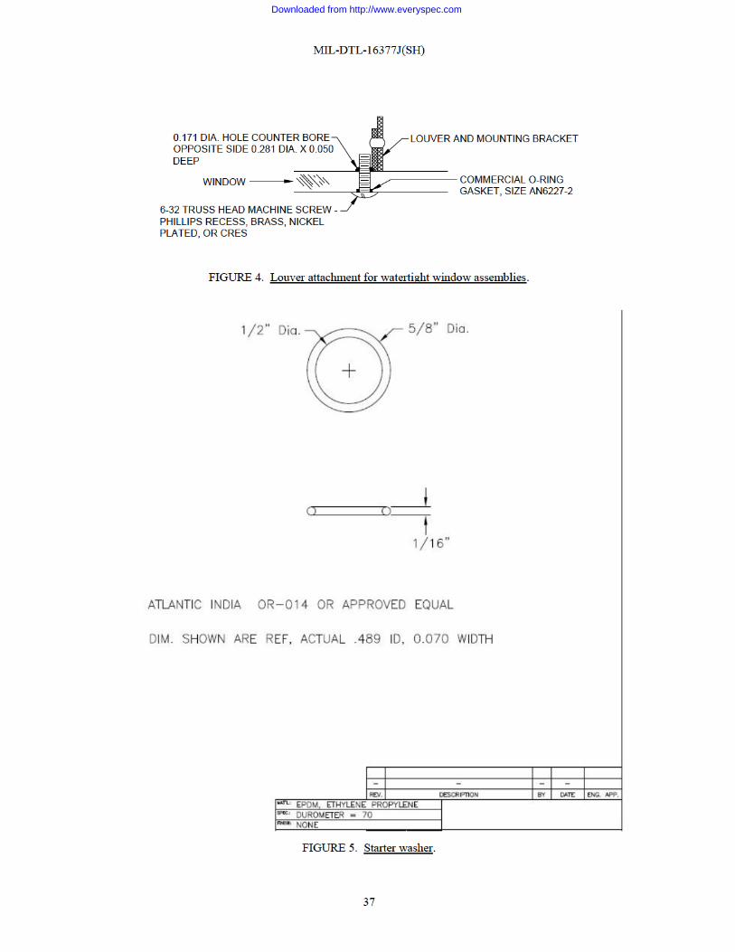
Downloaded from http://www.everyspec.com

MIL-DTL-16377J(SH)
38
FIGURE 6. Shockmount installation for type I, class 2 fixture.
332R
332R
INTEGRALLY CAST
INTEGRALLY FORMED
DETAIL SHOWING SHOCKMOUNT STOPS
30°
316
178
12 DIA.
1332 DIA. X 0.050DEEP FOR O-RING
0.257 DIA. HOLE FORSHOCKMOUNT BOLT
SHOCKMOUNT
HOUSINGSHOCKMOUNT STOP
DOME WASHER
HEX NUT
SHOCKMOUNT ASSEMBLY
COMMERCIAL O-RINGGASKET SIZE AN6227-5
1412°
1412°
516
516
1"0.075
+0.005-0.003
DEEPDETENT
118 DIA.
CLEARANCE HOLE
FOR #14 SCREW
INTERNALTOOTH EXTERNAL
TOOTHWASHER, INTERNAL - EXTERNAL TOOTH,DOME TYPE, 0.04 MIN. THICK, STEEL.
332 MIN.
1732 MIN. FLAT
Downloaded from http://www.everyspec.com

MIL-DTL-16377J(SH)
39
FIGURE 7. Dimensions for gasket groove and methods for retaining O-ring gasket for type I, class 2 fixtures.
DIMENSIONS FOR GASKET GROOVE
FIXTURE HOUSING
±0.010
+0.015-0.005
0.210
0.270
(A) CONTINUOUS RETAINER (B) DIMPLES (C) PINS
NOTES:1. CONTINUOUS GASKET RETAINER SHALL SPAN AT LEAST THE LENGTH SHOWN ON APPLICABLE
SPECIFICATION SHEET BY THE TWO (2) EXTREME NOTCHES ON EACH SIDE OF THE WINDOWASSEMBLIES.
2. LOCATION OF GASKET RETAINING DIMPLES OR PINS ON FIXTURE HOUSINGS SHALLCORRESPOND TO THE LOCATION OF THE NOTCHES SHOWN ON APPLICABLE SPECIFICATIONSHEET FOR THE WINDOW ASSEMBLIES.
METHODS OF RETAINING O-RING GASKET
ROUND CORNERS
CAST OR PUNCHEDDIMPLES
0.0900.088 DIA.
RETAINING PINS0.0900.088 DIA.
DRIVE FIT IN HOLE,CUT OFF AND SANDSMOOTH.
0.210±0.010
0.218±0.009
0.210±0.010
0.218±0.009
0.218±0.009
0.210±0.010
18 MIN.
Downloaded from http://www.everyspec.com

MIL-DTL-16377J(SH)
40
FIGURE 8. Chromaticity diagram illuminant A.
0.100 0.200 0.300 0.400 0.500 0.600 0.700 0.8000.0000.000
0.100
0.200
0.300
0.400
0.500
0.600
0.700
0.800
0.900
0.380
0.4300.450
0.4600.465
0 470
0.475
0.480
0.490
0 495
0.485
0.500
0.505
0.510
0.515
0.5200.525
0.530
0.535
0.540
0.545
0.550
0.555
0.560
0.565
0.570
0.575
0.580
0.585
0.590
0.595
0.600
0.605
0.6100.615
0.6200.625
0.6300.640
0.6500.770
x
y
0.000
0.100
0.200
0.300
0.400
0.500
0.600
0.700
0.800
0.900
y
MIXTURE DIAGRAMACCORDING TO THE 1931C.I.E. STANDARD OBSERVERAND COORDINATE SYSTEM
SPECIAL ENERGY LOCUS(WAVELENGTH IN NANOMETERS)
GREEN
CYAN
BLUE
RED
AMBER
Downloaded from http://www.everyspec.com

MIL-DTL-16377J(SH)
41
FIGURE 9. Light transmission curves of red glassware.
10
0
20
30
40
50
60
70
80
90
100
10
0
20
30
40
50
60
70
80
90
100
420 440 460 480 500 520 540 560 580 600 620 640 660 680 700WAVE LENGTH IN MILL MICRONS
EQ
UA
L D
IVIS
ION
SC
ALE
RE
FLE
CTI
ON
OR
TR
AN
SM
ISS
ION
PE
RC
EN
T
COMPUTATIONS IN TERMS OF 1931 ICISTANDARD OBSERVER AND COORDINATESYSTEM FOR COLORIMETRY - WITHILLUMINANT @ 2848 K. MEASUREDTRANSMISSION CURVES OF GLASSWARESHALL BE SYMETRICAL TO AND SHALL BEWITHIN ±20 PERCENT OF THE CURVESSHOWN HEREON. UNLESS OTHERWISESPECIFIED, MEASUREMENTS SHALL BEMADE AT 78 °F TEMPERATURE ONLY.
VISIBLETRANSMISSION* TEMPERATURE
25.3%
19.0%
13.7%
9.4%
78 °F
222 °F
346 °F
461 °F
Downloaded from http://www.everyspec.com

MIL-DTL-16377J(SH)
42
Illustration A: Standard Mount, White Diffusing Window
Illustration B: Flush Mount, Clear and White Prismatic Window
FIGURE 10. Typical styles of fluorescent lighting fixtures for general overhead lighting.
FIGURE 11. Type I labels.
EXAMPLEFOR EQUIPMENT IDENTIFICATION
MIL-F-16377/21ASYM. NO. 90.2
NSN 6210-00-548-0081JOHN DOE CO. TROY, NY
SYM. NO.
NATIONAL STOCK NO.
MANUFACTURERADDRESS
PURCHASE DOC. NO. ANDCURRENT REV. LETTER ATTIME OF MFR.
332 MIN.
18
18
18
116
332
MIN.
18
116
116
Downloaded from http://www.everyspec.com

MIL-DTL-16377J(SH)
43
FIGURE 12. Type II labels.
FIGURE 13. Type III labels.
FIGURE 14. Type IV labels.
INSTALL THE FOLLOWING LAMP ONLYNSN 6240-00-246-5054
TYPICAL INFORMATION LABEL
TYPICAL WIRING DIAGRAM LABEL
BALLASTTERMINALBLOCK
LINE115VAC
BLACKWIRE
WHITEWIRE
TO FIX
TUR
EFI
XT.
FOR SINGLE WHITE OR RED CIRCUIT: CONNECT WHITELEAD TO WHITE LINE TERMINAL. CONNECT RED AND BLACKLEADS TO OTHER LINE TERMINAL.FOR COMBINATION RED AND WHITE CIRCUITS:CONNECT WHITE LEAD TO WHITE LINE TERMINAL.CONNECT BLACK LEAD TO BLACK LINE TERMINAL.CONNECT RED LEAD TO RED LINE TERMINAL.
Downloaded from http://www.everyspec.com

MIL-DTL-16377J(SH)
44
FIGURE 15. Type V labels.
FIGURE 16. Type VI labels.
TYPICAL INFORMATION LABEL FOR WINDOWS THAT AREFURNISHED AS REPAIR PARTS.
NOTICE TO INSTALLERBEFORE INSTALLING WINDOW ASSEMBLY TO FIXTURE REMOVENUT, FLATWASHER, AND LOCKWASHER FROM CENTER SECURINGSCREW(S) WHEN FIXTURE PROVIDES FOR CENTER MOUNTING.ASSEMBLE WINDOW TO FIXTURE ONLY WITH SCREWS FURNISHED.NO ADDITIONAL SCREWS ARE NECESSARY. DISCARD LABEL ATASSEMBLY.
CAUTION SEE NOTE 1
SEE NOTE 2USE FUSE PULLER TO
CHANGE FUSES
NOTES:1. YELLOW WORDING ON BLACK.2. BLACK WORDING ON YELLOW.
3. MINIMUM HEIGHT OF LETTERS SHALL BE 332 INCH.
TYPICAL WARNING LABEL
Downloaded from http://www.everyspec.com

MIL-DTL-16377J(SH)
45
FIGURE 17. Standard methods of mounting lights for shock tests.
SHOCKMOUNT
MOUNTING PLATE
TYPICAL FIXTURE
(A) MOUNTING OF LIGHTS THAT AREFURNISHED WITH SHOCKMOUNTS
38-18 HEX NUT
34 OD X 13
32 ID FLATWASHER TO PREVENTSCORING OF SHOCKMOUNT
38-16 X 1 RHMS OR BOLT
MAXIMUM CLEARANCE ISREQUIRED TO PROVIDEMAXIMUM LATERAL SHOCKEXCURSION
Downloaded from http://www.everyspec.com

MIL-DTL-16377J(SH)
46
FIGURE 18. Typical ball impact equipment for shock test of glassware.
WIRING DIAGRAM
TYPICAL ELECTROMAGNET
115 VOLT SUPPLY
ELECTROMAGNET MOMENTARY CONTACT SWITCH,NORMALLY CLOSED.
HOLE FOR PLUMB LINE.
CUP POINT TO CAUSE BALLTO COME TO REST QUICKLYIN CENTERED POSITION.
12"2' 0"
WOODSPACER
SOFTWOOD
SMOOTH LEVELSURFACE
FLOOR LINE
BA
LL T
RA
VEL
DIS
TAN
CE
GLASS TO BE TESTED
HARDENED STEEL BALL(POLISHED)
ELECTROMAGNET SUFFICIENTLYPOWERFUL TO SUPPORT A5 LB STEEL BALL.
MAGNET SUPPORTING BRACKET - WOODADJUSTABLE VERTICALLY
CALIBRATED STEEL UPRIGHT -SUFFICIENTLY ADJUSTED VERTICALLYTO SUIT ALL SIZES OF GLOBEAND LENSES.
WALL
WING NUT
12"2' 0"
13"
6"
2"
Downloaded from http://www.everyspec.com
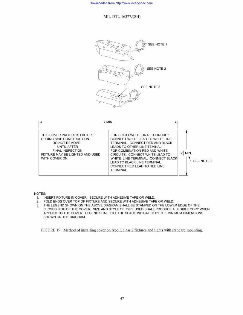
MIL-DTL-16377J(SH)
47
FIGURE 19. Method of installing cover on type I, class 2 fixtures and lights with standard mounting.
214 MIN.
SEE NOTE 3
7 MIN.
THIS COVER PROTECTS FIXTURE DURING SHIP CONSTRUCTION
DO NOT REMOVEUNTIL AFTER
FINAL INSPECTIONFIXTURE MAY BE LIGHTED AND USEDWITH COVER ON.
FOR SINGLEWHITE OR RED CIRCUIT:CONNECT WHITE LEAD TO WHITE LINETERMINAL. CONNECT RED AND BLACKLEADS TO OTHER LINE TEMINAL.FOR COMBINATION RED AND WHITECIRCUITS: CONNECT WHITE LEAD TOWHITE LINE TERMINAL. CONNECT BLACKLEAD TO BLACK LINE TERMINAL.CONNECT RED LEAD TO RED LINETERMINAL.
NOTES:1. INSERT FIXTURE IN COVER. SECURE WITH ADHESIVE TAPE OR WELD.2. FOLD ENDS OVER TOP OF FIXTURE AND SECURE WITH ADHESIVE TAPE OR WELD.3. THE LEGEND SHOWN ON THE ABOVE DIAGRAM SHALL BE STAMPED ON THE LOWER EDGE OF THE
CLOSED SIDE OF THE COVER. SIZE AND STYLE OF TYPE USED SHALL PRODUCE A LEGIBLE COPY WHENAPPLIED TO THE COVER. LEGEND SHALL FILL THE SPACE INDICATED BY THE MINIMUM DIMENSIONSSHOWN ON THE DIAGRAM.
SEE NOTE 3
SEE NOTE 2
SEE NOTE 1
Downloaded from http://www.everyspec.com

MIL-DTL-16377J(SH)
48
FIGURE 20. Airborne noise acceptable levels.
AMBIENT
LOW
ER LIMIT
UPPER LIMIT
AMBIENT+28DB
25
30
35
40
2520 30 35 40TEST AREA AMBIENT NOISE LEVEL DB REF. TO 0.0002 MBARS
AM
BIE
NT
PLU
S T
ES
T FI
XTU
RE
NO
ISE
Downloaded from http://www.everyspec.com

MIL-DTL-16377J(SH)
49
Lamp
(Watts) Dimension “A” (Inches) ±0.015″
6 9.360
8 12.360
15 18.150
20 24.150
FIGURE 21. Lampholder spacing.
FIGURE 22. Wiring diagram to operate one fluorescent lamp.
BLUEWIRE
LAMP
BALLAST
STARTER
CABLE
BLACK LEAD
WHITE LEAD
FLUORESCENT LAMP
LAMPHOLDER
LAMPHOLDER MOUNTING BRACKET
SEE DIMENSION "A"LAMPHOLDER SPACING
Downloaded from http://www.everyspec.com

MIL-DTL-16377J(SH)
50
FIGURE 23. Wiring diagram to operate two fluorescent lamps.
FIGURE 24. Wiring diagram to operate three fluores ent lamps.
LAMP
STARTER
BALLAST
LAMP
STARTER
BALLAST CABLE
WHITE LEAD
BLACK LEAD
RED LEAD
LAMP
STARTER
BALLAST
BLUE
RED CIRCUIT
WHITE CIRCUIT
BLUE
BLUE
FI URE 23 Wiring diagram t oper te two fluoresc nt lam
BLUE
LAMP
STARTER
BALLAST
LAMP
STARTER
BALLAST
CABLE
BLACK LEAD
RED LEAD
WHITE LEAD
BLUE
Downloaded from http://www.everyspec.com

MIL-DTL-16377J(SH)
51
Specification Sheet Symbol Number A B MIL-F-16377/5 338.1 and 339.1 13⅞ 4¾ MIL-DTL-16377/6 149.4 9¼ 7¼ MIL-DTL-16377/7 70.3 and 336 9¼ 4¾ MIL-DTL-16377/8 331.1 and 347.2 19⅞ 4¾ MIL-DTL-16377/9 73.3 and 346.2 9¼ 7¼ MIL-F-16377/10 145.4 19⅞ 7¼ MIL-DTL-16377/11 77.4 and 344.2 19⅞ 7¼ MIL-DTL-16377/12 333.1, 341.1, and 342.2 19⅞ 9¼ MIL-DTL-16377/14 80.1 and 79.1 9¼ 4¾ MIL-F-16377/65 81 and 345.2 13⅞ 7¼ MIL-F-16377/66 82 and 343.1 13⅞ 9¼
FIGURE 25. Mounting dimensions for standard mounting of fluorescent fixtures.
HOLES OF SHOCKMOUNTS
± 132CL
± 132A
MOUNTING BOLTS SHALL BE 38-16
CLB2
A2
B
A OR B
Downloaded from http://www.everyspec.com
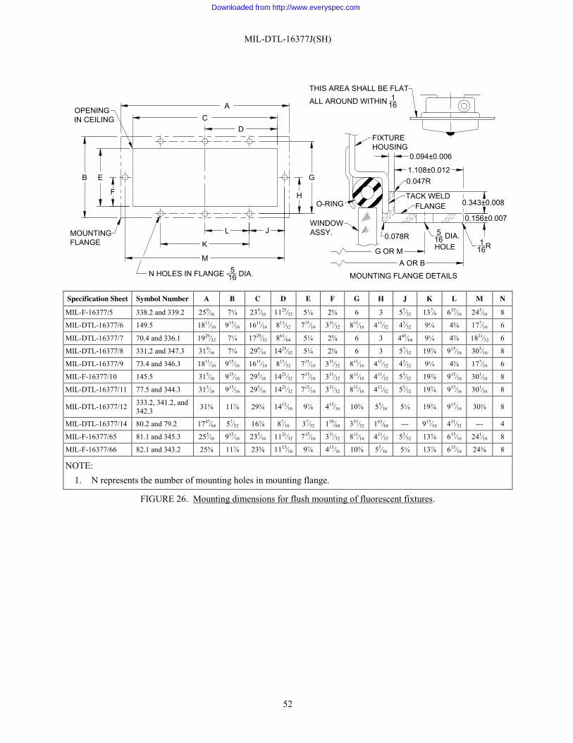
MIL-DTL-16377J(SH)
52
Specification Sheet Symbol Number A B C D E F G H J K L M N
MIL-F-16377/5 338.2 and 339.2 259⁄∕16 7¼ 239⁄∕16 1125⁄∕32 5¼ 2⅝ 6 3 57⁄∕32 137⁄∕9 615⁄∕16 245⁄∕16 8
MIL-DTL-16377/6 149.5 1811⁄∕16 915⁄∕16 1611⁄∕16 811⁄∕32 715⁄∕16 331⁄∕32 811⁄∕16 411⁄∕32 43⁄∕32 9¼ 4⅝ 177⁄∕16 6
MIL-DTL-16377/7 70.4 and 336.1 1929⁄∕32 7¼ 1729⁄∕32 861⁄∕64 5¼ 2⅝ 6 3 445⁄∕64 9¼ 4⅝ 1821⁄∕32 6
MIL-DTL-16377/8 331.2 and 347.3 319⁄∕16 7¼ 299⁄∕16 1425⁄∕32 5¼ 2⅝ 6 3 57⁄∕32 19⅞ 915⁄∕16 305⁄∕16 8
MIL-DTL-16377/9 73.4 and 346.3 1811⁄∕16 915⁄∕16 1611⁄∕16 811⁄∕32 715⁄∕16 331⁄∕32 811⁄∕16 411⁄∕32 43⁄∕32 9¼ 4⅝ 177⁄∕16 6
MIL-F-16377/10 145.5 315⁄∕16 915⁄∕16 295⁄∕16 1421⁄∕32 715⁄∕16 331⁄∕32 811⁄∕16 411⁄∕32 53⁄∕32 19⅞ 915⁄∕16 301⁄∕16 8
MIL-DTL-16377/11 77.5 and 344.3 315⁄∕16 915⁄∕16 295⁄∕16 1421⁄∕32 715⁄∕16 331⁄∕32 811⁄∕16 411⁄∕32 53⁄∕32 19⅞ 915⁄∕16 301⁄∕16 8
MIL-DTL-16377/12 333.2, 341.2, and 342.3 31⅝ 11⅞ 29⅝ 1413⁄∕16 9⅞ 415⁄∕16 10⅝ 55⁄∕16 5¼ 19⅞ 915⁄∕16 30⅜ 8
MIL-DTL-16377/14 80.2 and 79.2 1747⁄∕64 57⁄∕32 16⅞ 87⁄∕16 37⁄∕32 139⁄∕64 331⁄∕32 163⁄∕64 --- 915⁄∕16 431⁄∕32 --- 4
MIL-F-16377/65 81.1 and 345.3 255⁄∕16 915⁄∕16 235⁄∕16 1121⁄∕32 715⁄∕16 331⁄∕32 811⁄∕16 411⁄∕32 53⁄∕32 13⅞ 615⁄∕16 241⁄∕16 8
MIL-F-16377/66 82.1 and 343.2 25⅝ 11⅞ 23⅝ 1113⁄∕16 9⅞ 415⁄∕16 10⅝ 55⁄∕16 5¼ 13⅞ 615⁄∕16 24⅜ 8
NOTE: 1. N represents the number of mounting holes in mounting flange.
FIGURE 26. Mounting dimensions for flush mounting of fluorescent fixtures.
DC
A
H
G
F
EB
L J
K
M
N HOLES IN FLANGE - 516 DIA.
MOUNTINGFLANGE
OPENINGIN CEILING
THIS AREA SHALL BE FLAT
ALL AROUND WITHIN 116
FIXTUREHOUSING
WINDOWASSY.
O-RING
0.078R
FLANGE
516 DIA.HOLEG OR M
A OR B
MOUNTING FLANGE DETAILS
0.156±0.007
116R
TACK WELD
0.047R
0.343±0.008
1.108±0.012
0.094±0.006
Downloaded from http://www.everyspec.com

MIL-DTL-16377J(SH)
53
Military Part
No. Material Dimension No. of
Secrg. Scr. assy
No. of notches ea. side A B C D E F G H J K L M
M16377/5-001 Note 1 22.875 4.593 119⁄∕64 ⅛ 19.125 541⁄∕64 721⁄∕32 17 3 4
M16377/5-002 Note 2 22.797 4.562 M16377/7-001 Note 1 17.234 4.593
½ ⅛ 13.312 721⁄∕32 11 3 3 M16377/7-002 Note 2 17.187 4.562 M16377/8-001 Note 1 28.875 4.593
119⁄∕64 ⅛ 25.125 831⁄∕32 8¾ 23 3 4 M16377/8-003 Note 2 28.797 4.562 M16377/9-001 Note 1 16.015 7.265 31⁄∕32 7⁄∕16 11.782 79⁄∕64 11 3 3 M16377/9-003 Note 2 15.968 7.203 M16377/11-001 Note 1 28.656 7.265
1⅛ 9⁄∕16 8.333 8.396 25.125 8¾ 8¾ 23 4 4 M16377/11-003 Note 2 28.563 7.203 M16377/12-001 Note 1 28.937 9.234
131⁄∕64 25⁄∕32 8.333 8.396 25.125 91⁄∕32 8¾ 23 4 4 M16377/12-004 Note 2 28.844 9.141 M16377/65-001 Note 1 22.656 7.265
1⅛ 9⁄∕16 6.375 6.375 19.125 6¾ 6¾ 17 4 4 M16377/65-002 Note 2 22.563 7.203 M16377/66-001 Note 1 22.937 9.234
131⁄∕64 25⁄∕32 6.375 6.375 19.125 6¾ 6¾ 17 4 4 M16377/66-002 Note 2 22.844 9.141
NOTES:
1. Material shall be ¼ inch thick, white translucent acrylic plastic, Type WTLS-4, Grade G of MIL-DTL-24191.
2. Material shall be ¼ inch thick, clear prismatic acrylic plastic, Type CLEAR-2 of MIL-DTL-24191. The prisms shall be on the outside surface of the windows.
3. Short window securing screw assemblies in the number indicated on the table shall be installed as specified in 3.7.6.1.3.
4. When required, notches in the number indicated on the table shall be filed as shown as specified in 3.7.6.1.4.
5. Drill 0.191 diameter hole and counterbore opposite side 0.323 diameter, 0.050 deep. Break sharp edges on the inside surface on all holes.
6. Break sharp edges 1⁄∕64 of an inch around entire window.
7. The inside surface of both ends (bottom, sides, and end) of windows with clear prismatic material shall be finished white as specified in 3.8.4 1.
8. When required, one Type VI label shall be applied on the outside surface of the white translucent windows and on the inside surface of the clear and white prismatic windows as specified in 3 7.6.1.3.
FIGURE 27. Window assemblies.
FIGURE 27
0.250±0 035
A
C±1/32 (INSIDE)
150
150
NOTE 3
NOTE 3
J/2
E/2E±0.015 F±0 015
116R
J±1/32K±1/32 K±1/32 NOTE 6
NOTE 6
516R
116R
L±1/32 L±1/32
H/2H±0.031
G±0.031
SECTION A-A - SHOWING FOUR NOTCHES AND FOUR MOUNTING HOLES
SECTION A-A - SHOWING THREE NOTCHES AND THREE MOUNTING HOLES
CLC
C
NOTE 5NOTE 4
B
B NOTE 5
14R AA
NOTE 7 M/2±1/32M±1/16
12R
THE SURFACE SHALL BEFLAT ALL AROUNDWITHIN 1/16
A
SECTION B-B
SECTION C-C
7325
16R
18
+1/16-1/32
116 ±1/32
DETAILS FOR WINDOW NOTCH(THESE DIMENSIONS MAY VARY ONPRISMATIC WINDOWS DUE TOIRREGULAR INTERSECTIONS OFNOTCHES WITH PRISM)
AT PROJECTEDSHARP CORNER
D±1/32
3/4 FLAT
516R
116R
Downloaded from http://www.everyspec.com

MIL-DTL-16377J(SH)
54
Specification Symbol “A” DIA. MIL-F-16377/20 64.1 and 65 7⅝ MIL-F-16377/21 89 and 90.2 7⅝ MIL-F-16377/22 94.1 7⅝ MIL-F-16377/23 57, 57.1, 69, and 69.1 7⅝ MIL-F-16377/24 66.2 11¼ MIL-F-16377/25 48.2 and 68.2 7⅝ MIL-DTL 16377/26 112 and 113 7⅝ MIL-F-16377/64 67 7⅝
FIGURE 28. Mounting dimensions for incandescent fixtures.
MOUNTING PLATE
SHOCKMOUNT
TYPICAL LIGHTINGFIXTURE
1332 DIA. HOLE IN SHOCKMOUNT
MOUNTING BOLTS SHALL
BE 38-16
IGURE 28. Mount mensions fo tur
"A"
Downloaded from http://www.everyspec.com

MIL-DTL-16377J(SH) APPENDIX A
55
CERTIFICATION/DATA REPORT TECHNICAL CONTENT REQUIREMENTS
A.1 SCOPE
A.1.1 Scope. This Appendix covers information that should be included in the certification/data report when specified in the contract or order. This Appendix is not a mandatory part of the specification. The information contained herein is intended for guidance only.
A.2 CERTIFICATION CONTENT
A.2.1 Certification of drawings acceptance. A prerequisite to submission of the first article for inspection should be provision of satisfactory evidence to the contracting activity that the Naval Sea Systems Command (NAVSEA) (see 6.6) has reviewed and accepted the manufacturing drawings for the fixture, light, or part to be furnished under this specification. The contractor should provide drawing acceptance procedures, drawings, and certification data sheets in accordance with the data ordering documents included in the contract or order, and as specified in A.2.1.1 through A.2.1.1.2.
A.2.1.1 Drawing acceptance procedures. Two sets of prints of the manufacturing drawings for the fixture, light, or part followed by two sets of prints of the certification data sheet should be provided for review. Acceptance should be based upon the completeness of the drawing and other data submitted by the contractor conclusively providing proof of proper performance of the fixture, light, or part in accordance with this specification and the applicable specification sheet. Drawing acceptance should be obtained in writing.
A.2.1.1.1 Submission of revised drawings. When a drawing is not accepted, submission of a revised drawing should be accomplished. In addition, NAVSEA may require other drawings and documents for reference.
A.2.1.1.2 Changes. The contractor should make no changes in any accepted drawing, as they will require re-approval by NAVSEA. If changes are required, revised drawings should be submitted as specified in A.2.1.1.
Downloaded from http://www.everyspec.com
MIL-DTL-16377J(SH)
56
Preparing activity:
Navy – SH (Project 6210-2013-004)
NOTE: The activities listed above were interested in this document as of the date of this document. Since organizations and responsibilities can change, you should verify the currency of the information above using the ASSIST Online database at https://assist.dla.mil.
Downloaded from http://www.everyspec.com