inch-pound mil- dtl -22520 g superseding mil-c...
TRANSCRIPT

DETAIL SPECIFICATION
CRIMPING TOOLS, WIRE TERMINATION, GENERAL SPECIFICATION FOR
This specification is approved for use by all Departments and Agencies of the Department ofDefense.
1. SCOPE
1.1 Scope. This specification covers the general requirements for crimping tools,accessories and inspection gages used for connecting removable contacts (such as; signal, power,coaxial, shielded, thermocouple, and filter pin contacts) coaxial connectors, shielded connectors,ferrules, terminals, end caps and splices to wire conductors for use in electric connectors, terminaljunction systems, and other electric or electronic components. The crimping tools and accessoriescovered by this specification are for use by the military and are the only connector assemblydevices to be qualified, procured and issued for military maintenance use.
1.2 Classification. Crimping tools covered by this specification are of the followingtypes: (see 6.2)
Type I - Tools that produce an indent termination.Type II - Tools that produce a formed termination.Type III - Tools that produce a compression termination.
AMSC N/A FSC 5120DISTRIBUTION STATEMENT A. Approved for public release; distribution is unlimited.
INCH-POUND
MIL-DTL-22520G12 September 1997SUPERSEDINGMIL-C-22520F19 March 1976
Beneficial comments (recommendations, additions, deletions) and any pertinent data which maybe of use in improving this document should be addressed to: Commander, Naval Air WarfareCenter Aircraft Division, Code 414100B120-3, Highway 547, Lakehurst, NJ 08733-5100, byusing the Standardization Document Improvement Proposal (DD Form 1426) appearing at theend of this document or by letter.
Downloaded from http://www.everyspec.com

MIL-DTL-22520G
2
2. APPLICABLE DOCUMENTS
2.1 General. The documents listed in this section are specified in sections 3 and 4 of thisspecification. This section does not include documents cited in other sections of this specificationor recommended for additional information or as examples. While every effort has been made toensure the completeness of this list, document users are cautioned that they must meet allspecified requirements documents cited in sections 3 and 4 of this specification, whether or notthey are listed.
2.2 Government documents.
2.2.1 Specifications and standards. The following specifications and standards form a partof this document to the extent specified herein. Unless otherwise specified, the issues of thesedocuments are those listed in the Department of Defense Index of Specifications and Standards(DoDISS) and supplement thereto, cited in the solicitation (see 6.2).
SPECIFICATIONS
FEDERAL
QQ-W-343 - Wire, Electrical, Copper (Uninsulated)
DEPARTMENT OF DEFENSE
MIL-T-7928 - Terminals, Lug Splices, Conductor; Crimp Style, Copper,General Specification for
MIL-A-8625 - Anodic Coatings for Aluminum and AluminumAlloys
MIL-F-21608 - Ferrule, Shield Terminating, Crimp StyleMIL-W-22759 - Wire, Electric, Fluoropolymer-Insulated, Copper or Copper
AlloyMIL-PRF-39012 - Connectors, Coaxial, Radio Frequency, General Specification
ForMIL-C-39029 - Contacts, Electrical Connector, General Specification ForMIL-W-81044 - Wire, Electric, Crosslinked Polyalkene, Crosslinked Alkane-
Imide Polymer, or Polyarlene Insulated, Copper or CopperAlloy
MIL-S-81824 - Splice, Electric, Permanent, Crimp Style, Copper, Insulated,Environment Resistant
MIL-W-16878 - Wire, Electrical, Insulated, General Specification For
(See supplement 1 for list of specification sheets.)
Downloaded from http://www.everyspec.com

MIL-DTL-22520G
3
STANDARDS
DEPARTMENT OF DEFENSE
MIL-STD-130 - Identification Marking of U.S. Military PropertyMIL-STD-202 - Test Methods for Electronic and Electrical Component PartsMIL-STD-889 - Dissimilar Metals
(Unless otherwise indicated, copies of the above specifications and standards are availablefrom the Standardization Document Order Desk, 700 Robbins Avenue, Building 4D, Philadelphia,PA 19111-5094.)
2.3 Non-Government publications. The following documents form a part of this documentto the extent specified herein. Unless otherwise specified, the issues of the documents which areDoD adopted are those listed in the issue of the DoDISS cited in the solicitation. Unlessotherwise specified, the issues of documents not listed in the DoDISS are the issues of thedocuments cited in the solicitation (see 6.2).
AMERICAN SOCIETY OF MECHANICAL ENGINEERS (ASME)
ASME-Y14.5 - Dimensioning and Tolerancing
(Application for copies should be addressed to American Society of Mechanical Engineers,345 East 47th Street, New York, NY 10017-2392.)
AMERICAN NATIONAL STANDARDS INSTITUTE (ANSI)
ANSI-Z540.1 - Laboratories, Calibration and Measuring Test Equipment
(Application for copies should be addressed to American National Standards Institute, 11West 42nd Street, New York, NY 10036.)
AMERICAN SOCIETY FOR TESTING AND MATERIALS (ASTM)
ASTM-B16 - Rod, Brass, Bar, and Shapes for Use inScrew Machines (Metric). (DoD Adopted)
ASTM-B133 - Copper, Rod, Bar, and Shapes (Metric). (DoD Adopted)ASTM-B272 - Copper Flat Products with finished (Rolled or Drawn) Edges
(Flat Wire and Strip). (DoD Adopted)
(Application for copies should be addressed to American Society for Testing and Materials,100 Barr Harbor Drive, West Conshohocken, Pa. 19428-2950.)
Downloaded from http://www.everyspec.com

MIL-DTL-22520G
4
AMERICAN SOCIETY FOR QUALITY CONTROL (ASQC)
ASQC-Z1.4 - Procedures, Sampling and Tables for Inspection ByAttributes. (DoD Adopted)
(Application for copies should be addressed to the American Society For Quality ControlP.O. Box 3005, 611 E. Wisconsin Avenue, Milwaukee, Wisconsin 53201-4606.)
SOCIETY OF AUTOMOTIVE ENGINEERS (SAE)
SAE-AIR1351 - Aerospace Electrical & Electronic Wiring, Devices and Accessories, Manufacturers’ Identification of.
(Application for copies should be addressed to the Society of Automotive Engineers, 400Commonwealth Drive, Warrendale, PA 15096.)
2.4 Order of precedence. In the event of any conflict between the text of this document andthe references cited herein (except for related associated specification sheets), the text of thisdocument takes precedence. Nothing in this document, however, supersedes applicable laws andregulations unless a specific exemption has been obtained.
3. REQUIREMENTS
3.l Specification sheets. The individual item requirements shall be as specified herein and inaccordance with the applicable specification sheets. In the event of any conflict between therequirements of this specification and the associated specification sheets, the latter shall govern.
3.1.2 Dimensions and tolerances. Dimensioning and tolerancing used in this document andassociated specification sheets shall be in accordance with ASME-Y14.5.
3.2 Qualification. Tools furnished under this specification shall be products that areauthorized by the qualifying activity for listing on the applicable qualified products list beforecontract award (see 4.3 and 6.3).
3.2.1 Use of military part numbers. Military part numbers shall not be applied to a product,except for qualification test samples (see 6.3), until notification has been received from theactivity responsible for qualification that the product has been approved for listing on the qualifiedproducts list.
3.3 Materials. Materials shall be as specified herein. However, when a definite material isnot specified, a material shall be used which will enable the tools to meet the performance andinterface requirements of this specification and the applicable specification sheets. Acceptance orapproval of any constituent material shall not be construed as a guarantee of the acceptance of thefinished product.
Downloaded from http://www.everyspec.com

MIL-DTL-22520G
5
3.3.1 Finish. Aluminum parts shall be anodized in accordance with MIL-A-8625 or ananodizing process that meets the performance requirements specified in section 3.5 of thisspecification. All other metal parts shall be made of corrosion-resistant material or protected tomeet the performance requirements of this specification. Color shall be as specified on theapplicable specification sheet. Cadmium plating shall not be used.
3.3.2 Dissimilar metals. When dissimilar metals are employed in intimate contact with eachother, protection against electrolytic corrosion shall be provided as specified inMIL-STD-889.
3.4 Design and construction. Tools and accessories shall be in accordance with theapplicable specification sheet.
3.4.1 Crimping operation.
3.4.1.1 Type I tools. When the tool is in the fully opened position, the contacts shall passfreely between the indenters, both before and after being crimped. All indenters shall be designedto travel with equal and simultaneous movement. The motion and dimensional configuration shallbe specified in the applicable specification sheets. The tool design shall provide for positiveclosed positioning for the indenters. The indenter closure selector shall have a positive detent ateach setting. The tool shall be designed such that they can meet specified closure with or withoutpositioners or turrets installed. All positioners and turrets shall provide positive location of wirebarrels for crimping for specified contacts.
3.4.1.2 Type II tools. The crimping operation shall be accomplished by the closure of a setof dies with the specified configuration (see 3.1). The movement of the opposing crimp dies shallbe perpendicular or radial to the mating die face, and the fully closed position shall be as specifiedon the applicable specification sheet.
3.4.1.2.1 Locator. When required (see 3.1), a locating device shall be incorporated on thecrimping dies or crimping tools for positioning the item to be crimped in the proper location priorto the initiation of the crimp cycle.
3.4.1.3 Type III tools. Operation of the tool shall be in accordance with the individualspecification sheet.
3.4.2 Tool malfunction. All tools shall be provided with a return mechanism and a fullcycling mechanism that shall not jam or malfunction if operated with or without a contact orconnector, and with or without a positioner, turret, or die. Any tool operation within the scope ofthis specification shall neither create a jammed mechanism nor impair the function of the tool.Metal particles from operation of the tool or the crimping operation shall not accumulate withinthe tool where they would contribute to or cause any malfunction of the tool mechanism.
Downloaded from http://www.everyspec.com

MIL-DTL-22520G
6
3.4.2.1 Full cycle mechanism. The full cycle mechanism shall be tamperproof so that itcannot be disengaged prior to or during the crimp cycle.
3.4.3 Removal of crimped parts. The crimped assembly shall be removed from the toolwithout impediment upon completion of the crimping operation.
3.4.4 Calibration. Tool calibration adjustments shall be accessible only when the tool isdisassembled. These adjustments shall be made only by the manufacturer or by an approvedcalibration laboratory as specified in ANSI-Z540.1.
3.4.5 Gages.
3.4.5.1 Inspection gages. The required “GO” and “NO-GO” gages shall be made availableby the tool manufacturer for performing the qualification and conformance inspection gaging testsspecified herein. These gages shall conform to the gaging limits specified on the applicable toolspecification sheet.
3.4.5.2 In-service gages. The gages to be supplied to the Government for maintenance useshall be in accordance with the gage specification sheet specified on the applicable toolspecification sheet.
3.5 Performance. Tools shall meet the test requirements of this specification.
a. Type I tools. Type I tools shall crimp MIL-C-39029 wire barrels and other electricalconnector contacts to wires as specified in the applicable component specification.
b. Type II tools. Type II tools shall crimp terminal splices, end caps conforming to MIL-T-7928 and MIL-S-81824, shielded or coaxial contacts, coaxial connectors conforming to MIL-PRF-39012, ferrules conforming to MIL-F-21608, and other connecting devices to wires orcables as specified in the applicable specification sheet.
c. Type III tools. Type III tools shall meet the requirements as specified in the applicablespecification sheet.
3.5.1 Gaging. Tools shall meet the gaging limits specified in the applicable specificationsheet when tested in accordance with 4.7.1.
3.5.2 Humidity (steady state). There shall be no damage to basic tools, turrets, positioners,or dies to impair operation when tested in accordance with 4.7.2.
3.5.3 Handle, indenter, and die return operation (full cycle). The return mechanism shallcompel the handles, indenters, and dies to automatically return to the fully open position whentested in accordance with 4.7.3. This requirement shall apply regardless of the plane or positionof the tool, with or without a wired assembly located in the tool.
Downloaded from http://www.everyspec.com

MIL-DTL-22520G
7
3.5.4 Ratcheting mechanism.
3.5.4.1 Type I tools. The ratchet shall hold above the “NO-GO” limit of the applicablespecification sheet when tested in accordance with 4.7.4.1.
3.5.4.2 Type II tools. When tested in accordance with 4.7.4.2, the opposing die faces shallmeet and the dies shall fully close before the ratchet releases. The force required to release theratchet mechanism shall be not less than 30 pounds and shall be not more than 50 pounds.
3.5.4.3 Type III tools. Type III tool operation shall be in accordance with the applicablespecification sheets.
3.5.5 High compression force. Type I and type II tools shall conform to the gagingrequirement of 3.5.1, after being subjected to a 150-pound compression force in accordance with4.7.5. High compression force, if required, for type III tools shall be in accordance with theapplicable specification sheets.
3.5.6 Compression force. The force required to complete the cycle of the tool shall notexceed the value specified on the applicable specification sheet when tested in accordance with4.7.6.
3.5.7 Deformation of crimped connection.
3.5.7.1 Type I tools. The out-of-roundness of the crimped wire barrel shall be not greaterthan the specified maximum diameter of the barrel by more than 0.002 inch for sizes smaller thansize 20 or by more than 0.006 inch for size 20 and larger wire barrels when measured as specifiedin 4.7.7.1.
3.5.7.2 Type II tools. The crimped connection shall be symmetrical to ensure that thecomponent shall function as required when examined as specified in 4.7.7.2.
3.5.7.3 Type III tools. Deformation requirements shall be in accordance with applicablespecification sheets, if applicable.
3.5.8 Cracking of crimped connection. There shall not be any cracks penetrating the plating(or insulation, if applicable) and exposing the basis metal as a result of crimping, when tested asspecified in 4.7.8.
3.5.9 Concentricity (straightness).
3.5.9.1 Type I tools. The position of the outside diameter of the contact after being crimpedshall be not greater than 0.012 inch (relative to measured contact diameter) of the OD asmanufactured for sizes 12 and 16 contacts and 0.011 inch (relative to measured contact diameter)for size 20 and smaller contacts, when measured as specified in 4.7.9.1. This includes the
Downloaded from http://www.everyspec.com

MIL-DTL-22520G
8
0.005 inch permitted during contact manufacturing. This test shall be waived for stamped andformed contacts or contacts whose configuration does not allow testing with measuringequipment (see figure 3).
3.5.9.2 Type II tools. The crimped wire assembly shall be straight to ensure that thecomponent shall function as required when examined as specified in 4.7.9.2.
3.5.9.3 Type III tools. Requirements for straightness shall be in accordance with theapplicable specification sheets.
3.5.10 Voltage drop.
3.5.10.1 Type I tools. The voltage drop across the crimped joint shall be not greater thanthe value specified in table I, when tested as specified in 4.7.10.1.
3.5.10.2 Type II tools. The voltage drop shall meet the requirements of the specification towhich the crimped item is qualified. If the component specification does not specify the voltagedrop, the values specified in table III shall apply when tested as specified in 4.7.10.2.
3.5.10.3 Type III tools. Voltage drop shall be in accordance with the applicablespecification sheets.
3.5.11 Tensile strength. When tested in accordance with 4.7.11, the wire shall not break at,or pull out of, the crimped joint. The connection shall not break or become distorted to the extentthat it is unfit for further use before the minimum tensile strength is reached as specified in tablesII and III.
3.5.12 Dielectric strength for Type II tools. When applicable (see 3.1), the insulation onterminals, splices, ferrules and end caps shall show no evidence of damage, arcing, or breakdown,when tested in accordance with 4.7.12.
3.5.13 Low temperature crimp. There shall be no binding of the tool handles, indenters,dies, or crimped wired assemblies when tested as specified in 4.7.13. The wired assemblies shallthen meet the requirements of 3.5.10 and 3.5.11.
3.5.14 Shock. Crimping tools, turrets. positioners, or dies shall not be damaged as a resultof the shock test of 4.7.14.
Downloaded from http://www.everyspec.com

MIL-DTL-22520G
9
TABLE I. Voltage drop for type I tools.
Maximum voltage dropWire Test Silver- or tin-plated Nickel-platedsize current copper wire copper wire
range (amps) (millivolts) (millivolts)0000 225.0 6.0 N/A00 185.0 8.0 N/A0 150.0 3.0 N/A2 N/A N/A N/A4 80.0 4.0 N/A6 60.0 4.5 N/A8 46.0 5.0 N/A
10 33.0 4.0 N/A12 23.0 3.0 14.014 17.0 3.5 13.516 13.0 3.5 16.020 7.5 4.0 15.522 5.0 4.0 22.524 3.0 4.0 15.526 2.0 4.0 17.028 1.5 5.0 18.530 1.0 6.0 21.032 0.5 8.0 19.0
Downloaded from http://www.everyspec.com

MIL-DTL-22520G
10
TABLE II. Tensile strength for type I tools.
Minimum tensile strength (pounds)Wire size range Silver- or tin-plated copper wire Nickel-plated copper wire
Initial After low temp. crimp Initial After low temp. crimp0000 875.0 787.5 785.0 706.500 750.0 675.0 675.0 607.50 700.0 630.0 630.0 567.01 650.0 585.0 585.0 526.52 550.0 495.0 495.0 445.54 400.0 360.0 360.0 324.06 300.0 270.0 270.0 243.08 220.0 198.0 200.0 180.010 150.0 135.0 135.0 121.512 110.0 93.0 100.0 85.014 70.0 61.0 60.0 53.016 50.0 45.0 37.0 33.020 20.0 14.0 19.0 13.022 12.0 7.0 8.0 5.024 8.0 5.0 6.0 4.026 5.0 4.0 3.0 2.528 3.0 1.5 2.0 1.030 1.5 0.8 1.5 0.832 1.0 0.5 1.0 0.5
TABLE III. Voltage drop and tensile strength for terminals and splices used with type II tools.
Terminaland
splice
Wiresize
range
Testcurrent(amps)
Maximum voltage drop -millivolt drop of equivalent
length of wire plus this value*
Minimumtensile strength
(pounds)Terminal (mV) Splice (mV)
12-10 10 55.0 1.0 2.0 150.012 41.0 1.0 2.0 110.0
16-14 14 32.0 1.0 2.0 70.016 22.0 1.0 2.0 50.0
22-18 18 16.0 1.0 2.0 38.022 9.0 1.0 2.0 19.0
24-20 20 11.0 1.0 2.0 15.024 4.5 2.0 4.0 10.0
26-24 24 4.5 2.0 4.0 10.026 3.0 3.0 6.0 7.0
*For silver and tin plated wire only.
Downloaded from http://www.everyspec.com

MIL-DTL-22520G
11
3.5.15 Life requirements.
3.5.15.1 Type I tools. The tools shall be subjected to 200,000 crimping cycles in accordancewith 4.7.15.1. The wired contacts crimped during the life test shall meet the requirements of3.5.10 and 3.5.11. The tool shall meet the in-service requirements of 3.5.1 and the requirementsof 3.5.3 and 3.5.4.
3.5.15.2 Type II tools. The tool shall be subjected to 25,000 crimping cycles in accordancewith 4.7.15.2. The wired assemblies crimped during the life test shall meet the requirements of3.5.10 and 3.5.11. The tool shall meet the in-service requirements of 3.5.1 and the requirementsof 3.5.3 and 3.5.4.
3.5.15.3 Type III tools. The life requirements of type III tools shall be in accordance withthe applicable specification sheets.
3.5.16 Salt spray (corrosion). There shall not be any damage to basic tools, turrets,positioners, or dies that impairs operation, or evidence of corrosion when tested in accordancewith 4.7.16.
3.6 Marking. All marking shall be in accordance with MIL-STD-130 and shall bepermanently legible using either nameplates, dataplates, or direct marking.
3.6.l Manufacturer’s identification. The manufacturer's name and symbol, or only thesymbol shall be marked in the area specified on the specification sheet. The symbol alone shall beused when the available space does not allow for legible marking of the manufacturer's name. If asymbol is used, it shall be a symbol listed in SAE-AIR1351.
3.6.2 Nameplates and dataplates. Nameplates and dataplates on tools shall be marked withinformation in accordance with the applicable specification sheet. The material of the plates andthe mounting of the plates shall be capable of withstanding the environmental tests specified forthe item. Marking shall be permanent to the extent required for utilization of the item.
3.6.3 Direct markings. Basic tools, turrets, positioners, dies, and gages shall be directlymarked with information in accordance with the applicable specification sheet. Military partnumbers shall be permanently marked on the dies and gages.
3.7 Workmanship. Basic tools, turrets, positioners, dies, gages shall meet all designdimensions and requirements of this specification. The tools shall contain no sharp edges orburrs.
Downloaded from http://www.everyspec.com

MIL-DTL-22520G
12
4. VERIFICATION
4.1 Classification of inspection. The inspection requirements herein are classified as follows:
a. Qualification inspection (see 4.3).
b. Conformance inspection (see 4.4).
4.2 Inspection conditions. Unless otherwise specified herein or in the applicablespecification sheet, all inspections shall be performed in accordance with the test conditionsspecified as follows:
Temperature: 15 to 35 °C (59 to 95 °F).Relative humidity: 20 to 80 percent.Barometric pressure: 550 to 800 millimeters of mercury.
4.3 Qualification inspection. Qualification inspection shall consist of subjecting thequalification test samples specified in 4.3.1 to the applicable examinations and tests of table IV, inthe sequence shown. The qualifying activity may require that the manufacturer provide additionalsamples for initial qualification testing or retention of qualification testing.
4.3.1 Qualification test samples. The test samples shall consist of the samples specified in4.3.1.1 through 4.3.1.4.
4.3.1.1 Type I tools.
a. Two of the same part numbered basic tools and turrets or positioners for whichqualification is required shall be tested, except only one basic tool shall be subjected to the life test(see 4.7.15.1). This signifies qualification approval of both the basic tool and the turret orpositioner tested.
b. After approval of items in 4.3.1.1a, qualification approval of additional part numberedturrets or positioners shall be obtained by testing two of each additional turret or positioner withtwo previously qualified basic tools.
c. Qualification approval of turrets or positioners alone shall be obtained by testing two ofeach part numbered turret or positioner with two previously qualified basic tools.
Downloaded from http://www.everyspec.com

MIL-DTL-22520G
13
TABLE IV. Qualification inspection.
Type I Type IIExamination or
TestRequirement
ParagraphTest
paragraphBasic tools(4.3.1.1a)
Turrets orpositioners
(4.3.1.1b, c)
Basic tools(4.3.1.2a)
Dies(4.3.1.2b, c)
Visual and mechanicalexamination
3.1, 3.3, 3.3.1,3.3.2, 3.4, 3.6,
3.6.1, 3.6.2,3.6.3, 3.7
4.5 X X X X
Inspection gagingHumidity (steady state)In-service gagingHandle, indenter and die return operation (full cycling)
3.5.13.5.23.5.1
3.5.3
4.7.1.14.7.2
4.7.1.2
4.7.3
XXX
X
X------
---
XXX
X
X------
---Ratcheting mechanismHigh compression forceCompression forceDeformation of crimped connectionCracking of crimped connectionConcentricity (straightness)
3.5.43.5.53.5.6
3.5.7
3.5.8
3.5.9
4.7.44.7.54.7.6
4.7.7
4.7.8
4.7.9
XXX
X
X
X
---------
X
X
X
XXX
X
X
X
---------
X
X
XVoltage dropTensile strengthDielectric strengthLow temperature crimpCompression forceVoltage dropTensile strength
3.5.103.5.113.5.123.5.133.5.63.5.103.5.11
4.7.104.7.114.7.124.7.134.7.64.7.104.7.11
XX---XXXX
XX---------------
1/X1/X2/XXXXX
X1/X1/X2/------------
ShockIn-service gagingHandle, indenter and die return operation (full cycling)Ratcheting mechanismLife
3.5.143.5.1
3.5.33.5.43.5.15
4.7.144.7.1.2
4.7.34.7.44.7.15
XX
3/XXX
------
---
------
XX
3/XXX
------
---
------
Voltage dropTensile strengthSalt spray (corrosion)In-service gagingHandle, indenter and die return operation (full cycling)Ratcheting mechanism
3.5.103.5.113.5.163.5.1
3.5.33.5.4
4.7.104.7.114.7.164.7.1.2
4.7.34.7.4
XXXX
3/XX
------------
------
XXXX
3/XX
------------
------
Visual and mechanicalexamination
3.1, 3.3, 3.3.1,3.3.2, 3.4, 3.6,
3.6.1, 3.6.2,3.6.3 thru 3.7
4.5 X X X X
1/ Applicable only to dies for crimping terminal lugs, splices, and end caps.2/ Applicable only to dies for crimping insulated terminal lugs, splices, end caps, and ferrules.3/ 4.7.3.1 and 4.7.3.2 not applicable.
Downloaded from http://www.everyspec.com

MIL-DTL-22520G
14
4.3.1.2 Type II tools.
a. Two of the same part numbered basic tools and dies for which qualification is requiredand two sets of dies specified on the applicable specification sheet shall be tested. Only one basictool shall be subjected to the life test (see 4.7.15.2). This signifies qualification approval of boththe basic tool and the dies tested.
b. After approval of items in 4.3.1.2a, qualification approval of additional part numbereddies shall be obtained by testing two of each additional die with two previously qualified basictools.
c. Qualification approval of dies alone shall be obtained by testing two of each partnumbered die with two previously qualified basic tools.
4.3.1.3 Type III tools. Test sample quantities and any special requirements shall be inaccordance with the applicable specification sheet.
4.3.1.4 Accessory testing. Two of the same part numbered items or accessories shall betested in accordance with the applicable specification sheet.
4.3.2 Qualification rejection. There shall be no failures during any examination or test of thebasic tools, turrets, positioners, and dies submitted for qualification test (see 3.2).
4.3.3 Retention of qualification. To retain qualification, the supplier shall forward to thequalifying activity at 18-month intervals a summary report of group A conformance inspections.At 36-month intervals, a group B conformance inspection report shall be submitted. Thequalifying activity shall establish the initial reporting date. The report shall consist of:
a. A summary of the results of the tests performed for inspection of product for delivery,Group A, indicating as a minimum the number of lots that have passed and the number that havefailed. The results of tests of all reworked lots shall be accounted for and identified.
b. The complete results of tests performed for qualification verification inspection, Group Bincluding the number and mode of failures. The test report shall include results of all qualificationverification inspection tests performed and completed during the 36-month period. If the testresults indicate non-conformance with specification requirements, and corrective actionacceptable to the qualifying activity has not been taken, action may be taken to remove the failingproduct from the qualified products list.
Failure to submit the report within 60 days after the end of each 36-month period may result inloss of qualification for the product. In addition to the periodic submission of inspection data, thesupplier shall immediately notify the qualifying activity at any time during the 36-month periodthat the inspection data indicates failure of the qualified product to meet the requirements of thisspecification.
Downloaded from http://www.everyspec.com

MIL-DTL-22520G
15
In the event that no production occurred during the reporting period, a report shall be submittedcertifying that the company still has the capabilities and facilities necessary to produce the item. Ifduring three consecutive reporting periods there has been no production, the manufacturer may berequired, at the discretion of the qualifying activity, to submit a representative product from eachgroup for testing in accordance with the qualification inspection requirements of 4.3.
4.4 Conformance inspection.
4.4.1 Group A and group B inspections. Conformance inspection shall consist of thefollowing:
a. Group A inspection (lot by lot) (see 4.4.2).b. Group B inspection (periodic) (see 4.4.3).
4.4.2 Group A inspection. Before acceptance, tools shall be selected in accordance withASQC-Z1.4, inspection level S-4. The tools shall be subjected to the examinations and tests inthe sequence specified in table V. Delivery of products that have passed the group A inspectionshall not be delayed pending the results of the group B inspection. Group A rejection andreinspection shall be in accordance with the procedures of ASQC-Z1.4.
4.4.2.1 Disposition of group A samples. Tools that have met all the group A inspections arepermitted to be used on the contract or purchase order if the lot is accepted and the sample unitsare still within specified tolerance.
Downloaded from http://www.everyspec.com

MIL-DTL-22520G
16
TABLE V. Group A inspection.
Type I Type IIExamination or
TestRequirement
paragraphTest
paragraphBasic tools(4.3.1.1a)
Turrets orpositioners
(4.3.1.1b, c)
Basic tools(4.3.1.2a)
Dies(4.3.1.2b,c)
Visual and mechanical examination
3.1, 3.3, 3.3.1,3.3.2, 3.4, 3.6,3.6.1, 3.6.2,3.6.3, 3.7
4.5 X X X X
Inspection gagingHandle, indenter and die return operation (full cycling)Ratcheting mechanismHigh compression force
3.5.1
3.5.3
3.5.43.5.5
4.7.1.1
4.7.3
4.7.44.7.5
X
1/X
XX
X
---
---
---
X
1/X
XX
X
---
------
Deformation of crimped connectionConcentricity (straightness)Tensile strength
3.5.7
3.5.9
3.5.11
4.7.7
4.7.9
4.7.11
X
X
X
X
X
X
X
---
---
X
---
---
1/ 4.7.3.1 and 4.7.3.2 if applicable.
4.4.3 Group B inspection. A periodic inspection shall be made at 36-month intervals fromthe date of the letter of notification of the qualification. Group B inspection shall consist of theexaminations and tests performed, or as required by the qualifying activity, in the sequencespecified in table VI on one sample unit selected from inspection lots that have passed thegroup A inspection. Group B rejection and reinspection shall be in accordance with theprocedures of ASQC-Z1.4.
4.4.3.1 Disposition of Group B samples. Sample units that have been subjected to group Binspection shall not be delivered on the contract or purchase order.
Downloaded from http://www.everyspec.com

MIL-DTL-22520G
17
TABLE VI. Group B inspection.
Type I Type II
Examination or test Requirementparagraph
Testparagraph
Basictools
(4.3.1.1a)
Turrets orpositioners
(4.3.1.1b, c)
Basictools
(4.3.1.2a)
Dies(4.3.1.2b,c)
Inspection gagingCompression forceDeformation of crimped connectionCracking of crimped connection
3.5.13.5.63.5.7
3.5.8
4.7.1.24.7.64.7.7
4.7.8
XXX
X
X----X
X
XXX
X
X----X
X
Concentricity (straightness)Voltage dropTensile strength
3.5.9
3.5.103.5.11
4.7.9
4.7.104.7.11
X
XX
X
X----
----
--------
----
1/X1/X
Low temperature crimpCompression forceVoltage dropTensile strengthShock
3.5.133.5.63.5.103.5.113.5.14
4.7.134.7.6
4.7.104.7.114.7.14
XXXXX
--------------------
XX
--------X
--------------------
In-service gagingHandle, indentor and die return operation (full cycling)Ratcheting mechanism
3.5.1
3.5.3
3.5.4
4.7.1.2
4.7.3
4.7.4
X
X
X
----
----
----
X
X
X
----
----
----
Visual and mechanicalexaminations
3.1, 3.3,3.3.1, 3.3.2,3.4, 3.6,3.6.1, 3.6.2,3.6.3, 3.7
4.5 X X X X
1/ Applicable only to dies for crimping terminal lugs, splices, and end caps.
4.5 Visual and mechanical inspection. The tools, accessories, piece parts, and tool gagesshall be examined to ensure conformance with requirements of this specification and theapplicable specification sheet not covered by the performance requirements of 3.5. In-processcontrols of component parts, unrelated to lot sizes of finished tools, may be utilized in lieu ofexamination of these components in the finished tools to ensure conformance of these componentparts. Examination in a continuing manner shall be performed to ensure compliance with thefollowing requirements:
a. Applicable specification sheet (see 3.1).b. Materials (see 3.3).c. Finish (see 3.3.1 and 3.3.2).d. Design and construction (including dimensions) (see 3.4).e. Marking (see 3.6, 3.6.1., 3.6.2, and 3.6.3).f. Workmanship (see 3.7).
Downloaded from http://www.everyspec.com

MIL-DTL-22520G
18
4.6. Wired assemblies. Wired assemblies crimped during the tests specified in 4.7 shall bemade with lengths of silver-, tin-, or nickel-plated wire conforming to MIL-W-22759,MIL-W-16878, MIL-W-81044, or as specified in the applicable specification sheet (see 3.1).
4.7 Test methods.
4.7.1 Gaging. Activate the tool to the fully closed position. The "GO" gage shall be freelyinserted in the space between the opposing closed indenters or dies of the tool. With the "GO"pin in this position, the pressure on the tool handles shall be released, and the tool shallautomatically return to its fully open position. Close the tool to the fully closed position. The"NO-GO" pin of the gage shall not be insertable between the opposing indenters or dies of thetool. Type III tools shall be gaged or otherwise calibrated in accordance with applicablespecification sheets.
4.7.1.1 Inspection gaging. Indenter or die closures shall be tested with the inspection gagesspecified in 3.4.5.1 and shall meet the requirements of 3.5.1.
4.7.1.2 In-service gaging. Indenter or die closures shall be tested with the in-service gagespecified in 3.4.5.2, or with the manufacturer's equivalent inspection gage, and shall meet therequirements of 3.5.1.
4.7.2 Humidity (steady state). The basic tool, with its turret, positioner, or die installed shallbe exposed to steady state humidity in accordance with MIL-STD-202, method 103, condition A.The basic tool and turret, positioner, and die shall meet the requirements of 3.5.2.
4.7.3 Handle, indenter, and die return operation (full cycling). The tool shall be activated tothe fully closed position without a wired assembly in the tool, and then the hand pressure shall bereleased from the tool. This operation shall be repeated several times.
4.7.3.1 Type I tools. The tool shall be operated again to make up 20 wired assemblies foreach contact size and wire accommodated by the tool and turret or positioner under test. Tenwired assemblies shall be made with the largest size wire accommodated by the contact asspecified in table VII and 10 wired assemblies with the smallest size wire. The three wiredassemblies made up as specified in 4.7.6.1 may be considered as being included in the totalnumber specified above. Upon completion of each operation of the tool and release of the appliedpressure, the tool shall meet the requirements of 3.5.3.
4.7.3.2 Type II tools. The tool assembled with the dies as specified in the applicablespecification sheet shall be used to crimp 10 test ferrule assemblies as specified on figure 1 and theapplicable specification sheet. Assemblies, as specified in 4.7.6.2, may be considered as beingincluded in the total number specified. Upon completion of each operation of the tool and releaseof the applied pressure, the tool shall meet the requirements of 3.5.3.
Downloaded from http://www.everyspec.com

MIL-DTL-22520G
19
4.7.3.3 Type III tools. Test methods shall be in accordance with the applicable specificationsheet.
4.7.4 Ratcheting mechanism. When tested in accordance with 4.7.4.1, 4.7.4.2, or 4.7.4.3,tools shall meet the requirements of 3.5.4. Power tool cycle control test methods shall be asspecified in the applicable specification sheet.
4.7.4.1 Type I tools. The tool shall be closed on the "NO-GO" pin of the inspection gage inaccordance with the applicable specification sheet until a positive force is exerted by the indenterson the gage pin. CAUTION: DO NOT CRIMP THE GAGE. When the operator's handpressure is released, the tool shall meet the requirements of 3.5.4.1.
4.7.4.2 Type II tools. With dies installed having a combined height as specified in theapplicable specification sheet, a compression force shall be exerted on the handles of the tool,1.25 ±0.125 inches from the extremities of the handles. Without crimping a wired assembly, theforce required to release the ratcheting mechanism shall meet the requirements of 3.5.4.2.
4.7.4.3 Type III tools. Ratchet mechanism requirements shall be in accordance with theapplicable specification sheet.
4.7.5 High compression force. A compression force shall be exerted on the handles of thetool, 1.25 ±0.125 inches from the extremities of the handles at a rate of 5 pounds per second untila force of 150 pounds is reached. The force shall be applied while crimping the largest size wirebarrel with the largest size wire crimped by the type I tool, or the test ferrule specified in theapplicable specification sheet for the type II tool. The 150-pound force shall be continuouslyapplied for 30 seconds. The tool shall then be tested in accordance with 4.7.1.1 and shall meetthe requirements of 3.5.5.
4.7.6 Compression force.
4.7.6.1 Type I tools. The tool shall be mounted such that a compression force can beexerted on the handles, 1.25 ±0.125 inches from the extremities of the handles. Three contactswith the largest size wire barrel accommodated by the basic tool shall be crimped to the largestsize wire specified for them. The force necessary to make the crimps shall meet the requirementsof 3.5.6.
4.7.6.2 Type II tools. The tool shall be mounted as specified in 4.7.6.1. Test ferruleassemblies as specified on figure 1 and the applicable specification sheet shall be crimped. Theopposing dies shall close to a maximum gap of 0.010 inch and the force necessary to make thecrimps shall meet the requirements of 3.5.6. Three test ferrule assemblies as specified on figure 1and the applicable specification sheet shall be crimped.
Downloaded from http://www.everyspec.com
MIL-DTL-22520G
20
4.7.6.3 Type III tools. The compression force shall be in accordance with the applicablespecification sheet.
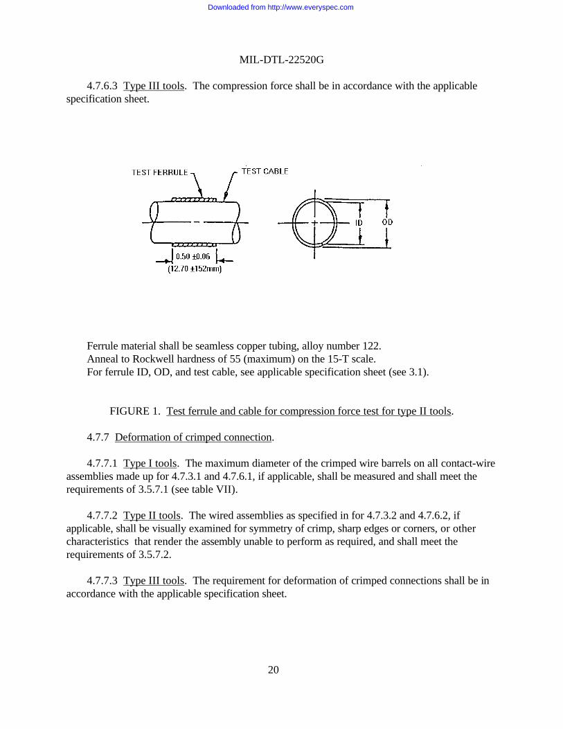
Ferrule material shall be seamless copper tubing, alloy number 122.Anneal to Rockwell hardness of 55 (maximum) on the 15-T scale.For ferrule ID, OD, and test cable, see applicable specification sheet (see 3.1).
FIGURE 1. Test ferrule and cable for compression force test for type II tools.
4.7.7 Deformation of crimped connection.
4.7.7.1 Type I tools. The maximum diameter of the crimped wire barrels on all contact-wireassemblies made up for 4.7.3.1 and 4.7.6.1, if applicable, shall be measured and shall meet therequirements of 3.5.7.1 (see table VII).
4.7.7.2 Type II tools. The wired assemblies as specified in for 4.7.3.2 and 4.7.6.2, ifapplicable, shall be visually examined for symmetry of crimp, sharp edges or corners, or othercharacteristics that render the assembly unable to perform as required, and shall meet therequirements of 3.5.7.2.
4.7.7.3 Type III tools. The requirement for deformation of crimped connections shall be inaccordance with the applicable specification sheet.
Downloaded from http://www.everyspec.com

MIL-DTL-22520G
21
TABLE VII. Wire barrel range accommodation.
Wire Barrel SizeWireSize
000 00 0 1 2 4 6 8 10 12 16 20 22 22D 22m3/
24 28
000000 1/X X
01
1/X XX X
24
1/X 1/X X1/X X
68
1/X 1/X X1/X X
1012
1/X X1/X X
1416
XX
1820
XX X
2224
XX
XX
XX X X
2628
X2/X
XX
XX
XX X
3032
XX
1/ With electrical conductive bushing.2/ Applies only to contact size 23-22.3/ Inactive for new design.
4.7.8 Cracking of crimped connection. The crimped connection of all wired assembliesmade up for 4.7.3 and 4.7.6, if applicable, shall be inspected with the aid of a magnifying devicehaving a power magnification of 10. The crimped connection shall meet the requirements of3.5.8.
4.7.9 Concentricity (straightness).
4.7.9.1 Type I tools. Six contact-wire assemblies are required for this test. Three of theassemblies prepared for 4.7.3.1 with the smallest size wire barrel accommodated by the tool andcrimped to the smallest size wire specified for that size contact shall be used. The other threeassemblies shall be the assemblies prepared for 4.7.6.1, if applicable, with the largest size wirespecified for that size contact. The wired contacts shall be chucked in the retention area shownon figure 2 and rotated. The total indicator reading (TIR) shall be taken at the diameters specified
Downloaded from http://www.everyspec.com

MIL-DTL-22520G
22
in the figure. The test setup shall be as shown on figure 3. The TIR measurements shall conformto 3.5.9.1.
4.7.9.2 Type II tools. The wired assemblies prepared for 4.7.3.2 and 4.7.6.2, if applicable,shall be visually examined for bending of tongues on terminals and curvature of splice bodies andshall meet the requirements of 3.5.9.2.
4.7.9.3 Type III tools. Concentricity for Type III tools shall be in accordance with theapplicable specification sheets.
For sizes 12 and larger pin contacts, Y = 0.05. For pin contacts smaller than size 12,Y = ½ the distance from the rear of the wire barrel to the beginning of the crimped indent.
FIGURE 2. Contact retention and measurement area concentricity test.
FIGURE 3. Test setup for concentricity measurement.
Downloaded from http://www.everyspec.com

MIL-DTL-22520G
23
4.7.10 Voltage drop.
4.7.10.1 Type I tools. The entire length of the contact-wire assemblies prepared for 4.7.3.1and 4.7.6.1, if applicable, shall be made to carry the applicable dc test current specified in tables Iand III. The test equipment fixture shall be set up in accordance with figure 4. After thetemperature stabilizes (approximately one minute), the voltage drop shall be measured with amillivolt measuring device attached from a point on the positioning shoulder to a point1/2 inch distant on the attached wire as shown on figure 4 and shall meet the requirements of3.5.10.1.
FIGURE 4. Voltage drop test (typical setup).
4.7.10.2 Type II tools. The wired assemblies prepared for 4.7.3.2 and 4.7.6.2, if applicable,shall be tested in accordance with the voltage drop of the specification to which the crimped itemis qualified and shall meet the requirements of the component specification sheet and 3.5.10.2.
4.7.10.3 Type III tools. The compression force shall be in accordance with the applicablespecification sheets.
4.7.11 Tensile strength. The wired assemblies prepared for 4.7.3 and 4.7.6, if applicable,shall be placed in a tensile testing device with appropriate fixtures, and a force shall be applied topull the wire out of the assembly or break the wire or crimped item. The speed of head travel ofthe tensile device shall be 1.0 ±0.25 inch per minute. The holding surfaces of the tensile deviceclamp may be serrated to provide sufficient gripping or holding strength. The wired assembliesshall meet the requirements of 3.5.11.
Downloaded from http://www.everyspec.com

MIL-DTL-22520G
24
4.7.12 Dielectric strength of type II tools (applicable only to dies for crimping insulatedterminal lugs, splices, end caps). Four wired assemblies of the largest size and typeaccommodated by the tool shall be prepared and tested in accordance with the dielectric strengthtest of the specification to which the crimp item is qualified, and shall meet the requirements ofthe component specification and 3.5.12.
4.7.13 Low temperature crimp. The basic tool, turret, positioner, or die, and the items to becrimped shall be exposed to a temperature of 15 °C for 2 hours. Immediately after removingthese items from the test chamber, while the tool is at the low temperature, the tool shall be usedto make its respective crimps. Four wire assemblies shall be made.
4.7.13.1 Type I tools. Two assemblies shall be made with the largest size wire barrel withthe largest size wire accommodated by the wire barrel. Two assemblies shall be made with thesmallest size wire barrel crimped by the tool with the smallest size wire accommodated by thewire barrel in accordance with table VII.
4.7.13.2 Type II tools. Two crimp assemblies shall be made with the type II tool using thetest ferrule and cable shown on figure 1 and the applicable specification sheet (see 3.1). Theassemblies shall meet the requirements specified in 3.5.6 and 3.5.12 (where applicable).
4.7.13.3 Type III tools. Not applicable to type III tools.
4.7.14 Shock. The tool, with a turret, positioner, or die installed, shall be loosely placed in a12 x 12 x 12-inch box made of 1/4-inch plywood, which has been rigidly fastened to the carriageof a shock test device. The box may be open at the top to facilitate accessibility to the tool. Thetool shall be subjected to a shock test in accordance with MIL-STD-202, method 213, testcondition I. Two shocks shall be applied, one with the contact entrance of the tool facing thebottom of the box and the other with the contact entrance facing away from the bottom. The toolshall meet the requirements of 3.5.14.
4.7.15 Life test.
4.7.15.1 Type I tools. Only one tool shall be tested. The tool shall be mounted such that itcan be mechanically actuated at a rate of 15 to 20 cycles per minute, where a cycle consists ofdepressing the handles of the tool to the fully closed or positive stop position and allowing thehandles to return to the fully opened position. The tool selector setting shall be set as specified intable VIII. A compression force shall be applied to the extremities of the handles to crimp testrods of the diameters and materials shown in table VIII, as applicable. For tools used to crimpsize 12 contacts, the rod shall be advanced a minimum of 1/4 inch after each crimp to provide anew crimping surface. For tools used to crimp size 16 and smaller contacts, the rod shall beadvanced a minimum of 1/8 inch. After every 50,000 cycles, the tool shall be manually operatedto crimp six wire-contact assemblies using the largest wire barrel that the basic tool is designed tocrimp. Three of the contacts shall be crimped to the largest size wire and three to the smallestsize wire accommodated by the contact. The tool shall not require adjustments or repairs during
Downloaded from http://www.everyspec.com

MIL-DTL-22520G
25
the 200,000 cycles, but it shall be permissible to remove foreign matter and lubricate the toolevery 50,000 cycles. The requirements of 3.5.15.1 shall be met.
4.7.15.2 Type II tools. Only one tool shall be tested. The tool shall be mounted such that itcan be mechanically actuated at a rate of 15 to 20 cycles per minute, where a cycle consists ofdepressing the handles of the tool to the fully closed or positive stop position and allowing thehandles to return to the fully opened position. A set of dies used to crimp the largest ferrule,terminal, or splice that the tool is designed to crimp shall be installed in the tool such that a 30 to50 pound handle force is required to release the ratcheting mechanism at the end of the normalcrimping cycle with no sample in the tool. After every 5,000 cycles, the tool shall be manuallyoperated to crimp six wired assemblies using the largest terminal, splice, or ferrule accommodatedby the tool. Three wired assemblies shall be crimped to the largest size wire or cable and threeassemblies crimped to the smallest size accommodated by the item. When only one size wire orcable is specified, only three samples shall be prepared. The tool shall not require adjustments orrepairs during the 25,000 cycles. The requirements of 3.5.15.2 shall be met.
TABLE VIII. Test rod for life test for type I tools.
Largest contactaccommodated
Selectorsetting
Rod dia. - in(+0.001)
Materialspecification
Physicalproperties
12 8 0.125 Commercial leadedbronze or
ASTM-B133 orASTM-B272
RockwellhardnessB50 +2
1620
78
0.064 ASTM-B16or QQ-W-343
Minimum tensilestrength
48,000 pounds persquare inch (psi)
4.7.16 Salt spray (corrosion). The basic tool with turret, positioner, or die installed shall besubjected to a salt spray (corrosion) test in accordance with MIL-STD-202, method 101,condition B. The salt solution shall be a 5 percent concentration. Immediately after removal fromthe chamber, the basic tool and turret, positioner, or die shall be rinsed in running water notwarmer than 38 °C and subsequently dried in a circulating air oven for 12 hours at a temperatureof 38 ±3 °C. Upon removal from the oven, the basic tool and turret, positioner, or die shall meetthe requirements of 3.5.16.
5. PACKAGING
5.1 Packaging. For acquisition purposes, the packaging requirements shall be as specified inthe contract or order (see 6.2). When actual packaging of materiel is to be performed by DoDpersonnel, these personnel need to contact the responsible packaging activity to ascertain requisitepackaging requirements. Packaging requirements are maintained by the Inventory Control Point’spackaging activity within the Military Department of Defense Agency, or within the MilitaryDepartment’s System Command. Packaging data retrieval is available from the managing Military
Downloaded from http://www.everyspec.com

MIL-DTL-22520G
26
Department’s or Defense Agency’s automated packaging files, CD-ROM products, or bycontacting the responsible packaging activity.
6. NOTES
(This section contains information of a general or explanatory nature which may be helpful,but is not mandatory.)
6.1 Intended use. Tools covered by this specification are intended for crimpingMIL-C-39029 removable contacts (e.g., power, coaxial, shielded, thermocouple and filter pincontacts); MIL-PRF-39012 coaxial connectors; MIL-T-7928 terminals, splices, and end caps;MIL-S-81824 splices; and MIL-F-21608 ferrules to wire conductors for use in electricconnectors, terminal junction systems, and other electric or electronic components. These toolsmay be used to crimp other connecting devices of design or materials other than those specifiedherein provided the required performance is obtained. Type III tools may be used for functions asspecified in their applicable specification sheets.
6.1.1 Tool selection. For tool selection, see the applicable component specification.
6.1.2 Type I tools. Crimping contacts without positioners or turrets (as applicable) is not arecommended practice.
6.2 Acquisition requirements. Acquisition documents must specify the following:
a. Title, number, and date of this specification and applicable specification sheet.
b. Issue of DoDISS to be cited in the solicitation, and if required, the specific issue of theindividual documents referenced (see 2.2.1).
c. Military part number for basic tools, turrets, positioners, dies, in-service gages, and othertools as required.
d. Quantity desired.
e. Packaging (see 5.1).
6.3 Qualification. With respect to products requiring qualification, awards will be made onlyfor products which are, at the time of award of contract, qualified for inclusion in qualifiedproducts list QPL No. 22520 whether or not such products have actually been so listed by thatdate. The attention of the contractors is called to these requirements, and manufacturers are urgedto arrange to have the products, that they propose to offer to the Federal Government, tested forqualification in order that they may be eligible to be awarded contracts or purchase orders for theproducts covered by this specification. Information pertaining to qualification of products may beobtained the Naval Air Warfare Center Aircraft Division Patuxant River, Code 4.5.6.1, Suite 5
Downloaded from http://www.everyspec.com

MIL-DTL-22520G
27
48142 Shaw Road, Unit 5, Patuxant River, MD. 20670.
6.4 Patent notice. The Government has a royalty-free license under the listed patents for thebenefit of manufacturers of the item either for the Government or for use in equipment to bedelivered to the Government.
U.S. patent applicationsU.S. patent numbers serial numbers
2,991,675 158,9563,059,511 172,1953,063,313 172,354
302,170617,783
6.6 Subject term (key word) listing.
ConnectorsConnectors, electricalContactsDiesEnd capsFerrulesGages, inspectionPositionersSplicesTerminalsTurretWire, electrical
6.7 Changes from previous issue. Marginal notations are not used in this revision to identifychanges with respect to the previous issue due to the extent of the changes.
CONCLUDING MATERIAL
Custodians: Preparing activity:Army - CR Navy - ASAir Force - 85
Review activities: (Project 5120-0085)Army - MI, AVNavy - SH, ECAir Force - 17, 99DLA - CC
Downloaded from http://www.everyspec.com

Downloaded from http://www.everyspec.com

STANDARDIZATION DOCUMENT IMPROVEMENT PROPOSAL
INSTRUCTIONS
1. The preparing activity must complete blocks 1, 2, 3, and 8. In block 1, both the document number and revision letter should begiven.
2. The submitter of this form must complete blocks 4, 5, 6, and 7.
3. The preparing activity must provide a reply within 30 days from receipt of the form.NOTE: This form may not be used to request copies of documents, nor to request waivers, or clarification of requirements oncurrent contracts. Comments submitted on this form do not constitute or imply authorization to waive any portion of the referenced document(s) or to amend contractual requirements.
I RECOMMEND A CHANGE: 1. DOCUMENT NUMBER
MIL-DTL-22520G2. DOCUMENT DATE (YYMMDD)
970917
3. DOCUMENT TITLE
CRIMPING TOOLS, WIRE TERMINATION, GENERAL SPECIFICATION FOR
4. NATURE OF CHANGE (Identify paragraph number and include proposed rewrite, if possible. Attach extra sheets as needed.)
5. REASON FOR RECOMMENDATION
6. SUBMITTER
a. NAME (Last, First, Middle Initial) b. ORGANIZATION
c. ADDRESS (Include Zip Code) d. TELEPHONE(Include Area Code)(1) Commercial:
(2) DSN: (If Applicable)
7. DATE SUBMITTED (YYMMDD)
8. PREPARING ACTIVITY
a. NAME COMMANDER NAVAL AIR WARFARE CENTER AIRCRAFT DIVISION
b. TELEPHONE NUMBER (Include Area Code)(1) Commercial (2) DSN (908) 323-2628 624-2628
c. ADDRESS (Include Zip Code) CODE 414100B120-3 HIGHWAY 547 LAKEHURST, NJ 08733-5100
IF YOU DO NOT RECEIVE A REPLY WITHIN 45 DAYS, CONTACT: Defense Quality and Standardization Office, 5203 Leesburg Pike, Suite 1403, Falls Church, VA 22041-3466 Telephone (703) 756-2340 DSN 289-2340
DD Form 1426, OCT 89 Previous editions are obsolete 198/290
Downloaded from http://www.everyspec.com

COMMANDERNAVAL AIR WARFARE CENTERAIRCRAFT DIVISIONCODE 414100B120-3HIGHWAY 547LAKEHURST, NJ 08733-5100
Downloaded from http://www.everyspec.com