flender zapex® couplings - siemens · pdf file6 / 28 ba 3561 en 12/2015 1. technical data...
TRANSCRIPT

FLENDER couplings
FLENDER ZAPEX®couplingsType ZNW
Operating instructionsBA 3561 en 12/2015

2 / 28BA 3561 en 12/2015
FLENDER ZAPEX®couplings
Type ZNW
Operating instructions
Translation of the original operating instructions
Technical data
Declarations
Stocking spare parts
Maintenanceand repair
Faults, causesand remedy
Start-upand operation
Fitting
Notes
1
8
7
6
5
4
3
2

3 / 28BA 3561 en 12/2015
Notes and symbols in these operating instructions
Note: The term "operating instructions" will in the following also be shortened to "instructions" or "manual".
The term "2014/34/EU" used in these instructions applies to the version designed in conformity to directive94/9/EC, if the product is put on the market by 19.04.2016, and to the version designed in conformity todirective 2014/34/EU, if the product is put on the market on or after 20.04.2016.
Legal notes
Warning-note concept
This manual comprises notes which must be observed for your personal safety and for preventing material damage.Notes for your personal safety are marked with a warning triangle or an "Ex" symbol (when applyingDirective 2014/34/EU), those only for preventing material damage with a "STOP" sign.
WARNING! Imminent explosion!
The notes indicated by this symbol are given to prevent explosion damage.Disregarding these notes may result in serious injury or death.
WARNING! Imminent personal injury!
The notes indicated by this symbol are given to prevent personal injury.Disregarding these notes may result in serious injury or death.
WARNING! Imminent damage to the product!
The notes indicated by this symbol are given to prevent damage to the product.Disregarding these notes may result in material damage.
NOTE!
The notes indicated by this symbol must be treated as general operating information.Disregarding these notes may result in undesirable results or conditions.
WARNING! Hot surfaces!
The notes indicated by this symbol are made to prevent risk of burns due to hot surfacesand must always be observed.Disregarding these notes may result in light or serious injury.
Where there is more than one hazard, the warning note for whichever hazard is the most serious is always used.If in a warning note a warning triangle is used to warn of possible personal injury, a warning of material damage maybe added to the same warning note.
Qualified personnel
The product or system to which these instructions relate may be handled only by persons qualified for the workconcerned and in accordance with the instructions relating to the work concerned, particularly the safety andwarning notes contained in those instructions. Qualified personnel must be specially trained and have theexperience necessary to recognise risks associated with these products or systems and to avoid possible hazards.

4 / 28BA 3561 en 12/2015
Intended use of Siemens products
Observe also the following:
Siemens products must be used only for the applications provided for in the catalogue and the relevanttechnical documentation. If products and components of other makes are used, they must berecommended or approved by Siemens. The faultfree, safe operation of the products calls for propertransport, proper storage, erection, assembly, installation, startup, operation and maintenance. Thepermissible ambient conditions must be adhered to. Notes in the relevant documentations must beobserved.
Trademarks
All designations indicated with the registered industrial property mark ® are registered trademarks of Siemens AG.Other designations used in these instructions may be trademarks the use of which by third parties for their ownpurposes may infringe holders’ rights.
Exclusion of liability
We have checked the content of the instructions for compliance with the hard and software described.Nevertheless, variances may occur, and so we can offer no warranty for complete agreement. The informationgiven in these instructions is regularly checked, and any necessary corrections are included in subsequent editions.
Note on the EC Machinery Directive 2006/42/EC
Siemens couplings in the "FLENDER couplings" product range must be treated as "components" in the senseof the EC Machinery Directive 2006/42/EC.Therefore, Siemens needs not issue a declaration of incorporation.Information on safe fitting, safe startup and safe operation can be found in this instructions manual; in additionthe "warningnote concept" therein must be observed.

5 / 28BA 3561 en 12/2015
Contents
1. Technical data 6. . . . . . . . . . . . . . . . . . . . . . . . . . . . . . . . . . . . . . . . . . . . . . . . . . . . .1.1 Torques, speeds, geometric data and weights 6. . . . . . . . . . . . . . . . . . . . . . . . . . . . . . . . . . . . . . . . . . .
1.2 Orings (12) 7. . . . . . . . . . . . . . . . . . . . . . . . . . . . . . . . . . . . . . . . . . . . . . . . . . . . . . . . . . . . . . . . . . . . . . . .
2. Notes 8. . . . . . . . . . . . . . . . . . . . . . . . . . . . . . . . . . . . . . . . . . . . . . . . . . . . . . . . . . . . .2.1 Safety instructions and general notes 8. . . . . . . . . . . . . . . . . . . . . . . . . . . . . . . . . . . . . . . . . . . . . . . . . .
2.2 Marking of the coupling parts for use in potentially explosive zones 9. . . . . . . . . . . . . . . . . . . . . . . . .
2.3 Service conditions 9. . . . . . . . . . . . . . . . . . . . . . . . . . . . . . . . . . . . . . . . . . . . . . . . . . . . . . . . . . . . . . . . . .
3. Fitting 10. . . . . . . . . . . . . . . . . . . . . . . . . . . . . . . . . . . . . . . . . . . . . . . . . . . . . . . . . . . . .3.1 Machining the finished bore 10. . . . . . . . . . . . . . . . . . . . . . . . . . . . . . . . . . . . . . . . . . . . . . . . . . . . . . . . . .
3.2 Machining the parallel keyway 10. . . . . . . . . . . . . . . . . . . . . . . . . . . . . . . . . . . . . . . . . . . . . . . . . . . . . . . .
3.3 Axial fastening 10. . . . . . . . . . . . . . . . . . . . . . . . . . . . . . . . . . . . . . . . . . . . . . . . . . . . . . . . . . . . . . . . . . . . . .
3.4 Balancing after machining the finished bore 12. . . . . . . . . . . . . . . . . . . . . . . . . . . . . . . . . . . . . . . . . . . . .
3.5 Placing the coupling parts (1; 3) in case of shafthub connection with parallel key 12. . . . . . . . . . . . .
3.6 Fitting of coupling parts (1; 3) in case of a cylindrical and tapered interference fit set upfor removal by oilhydraulic shrinkingoff 13. . . . . . . . . . . . . . . . . . . . . . . . . . . . . . . . . . . . . . . . . . . . . . . .
3.7 Installation of the coupling 13. . . . . . . . . . . . . . . . . . . . . . . . . . . . . . . . . . . . . . . . . . . . . . . . . . . . . . . . . . . .
3.8 Alignment 14. . . . . . . . . . . . . . . . . . . . . . . . . . . . . . . . . . . . . . . . . . . . . . . . . . . . . . . . . . . . . . . . . . . . . . . . . .
3.9 Possible misalignments 15. . . . . . . . . . . . . . . . . . . . . . . . . . . . . . . . . . . . . . . . . . . . . . . . . . . . . . . . . . . . . .
3.9.1 Axial misalignment 15. . . . . . . . . . . . . . . . . . . . . . . . . . . . . . . . . . . . . . . . . . . . . . . . . . . . . . . . . . . . . . . . . .
3.9.2 Angular misalignment 15. . . . . . . . . . . . . . . . . . . . . . . . . . . . . . . . . . . . . . . . . . . . . . . . . . . . . . . . . . . . . . . .
3.9.3 Radial misalignment 15. . . . . . . . . . . . . . . . . . . . . . . . . . . . . . . . . . . . . . . . . . . . . . . . . . . . . . . . . . . . . . . . .
3.10 Distance between teeth VA and recommended alignment values for angularand radial misalignment 16. . . . . . . . . . . . . . . . . . . . . . . . . . . . . . . . . . . . . . . . . . . . . . . . . . . . . . . . . . . . . .
3.11 Distance dimensions "S" 17. . . . . . . . . . . . . . . . . . . . . . . . . . . . . . . . . . . . . . . . . . . . . . . . . . . . . . . . . . . . .
3.12 Assignment of the tightening torques and wrench widths 17. . . . . . . . . . . . . . . . . . . . . . . . . . . . . . . . . .
4. Startup and operation 18. . . . . . . . . . . . . . . . . . . . . . . . . . . . . . . . . . . . . . . . . . . . .4.1 Requirements for grease 18. . . . . . . . . . . . . . . . . . . . . . . . . . . . . . . . . . . . . . . . . . . . . . . . . . . . . . . . . . . . .
4.2 Recommended lubricants 18. . . . . . . . . . . . . . . . . . . . . . . . . . . . . . . . . . . . . . . . . . . . . . . . . . . . . . . . . . . .
4.3 Grease quantity 19. . . . . . . . . . . . . . . . . . . . . . . . . . . . . . . . . . . . . . . . . . . . . . . . . . . . . . . . . . . . . . . . . . . . .
4.4 Procedure before startup 19. . . . . . . . . . . . . . . . . . . . . . . . . . . . . . . . . . . . . . . . . . . . . . . . . . . . . . . . . . . .
5. Faults, causes and remedy 20. . . . . . . . . . . . . . . . . . . . . . . . . . . . . . . . . . . . . . . . .5.1 Possible cause of fault 20. . . . . . . . . . . . . . . . . . . . . . . . . . . . . . . . . . . . . . . . . . . . . . . . . . . . . . . . . . . . . . .
5.2 Incorrect use 20. . . . . . . . . . . . . . . . . . . . . . . . . . . . . . . . . . . . . . . . . . . . . . . . . . . . . . . . . . . . . . . . . . . . . . .
5.2.1 Frequent faults when selecting the coupling and/or coupling size 20. . . . . . . . . . . . . . . . . . . . . . . . . . .
5.2.2 Frequent faults when fitting the coupling 21. . . . . . . . . . . . . . . . . . . . . . . . . . . . . . . . . . . . . . . . . . . . . . . .
5.2.3 Frequent faults in maintenance 21. . . . . . . . . . . . . . . . . . . . . . . . . . . . . . . . . . . . . . . . . . . . . . . . . . . . . . . .
6. Maintenance and repair 21. . . . . . . . . . . . . . . . . . . . . . . . . . . . . . . . . . . . . . . . . . . .6.1 General 21. . . . . . . . . . . . . . . . . . . . . . . . . . . . . . . . . . . . . . . . . . . . . . . . . . . . . . . . . . . . . . . . . . . . . . . . . . . .
6.2 Changing grease 22. . . . . . . . . . . . . . . . . . . . . . . . . . . . . . . . . . . . . . . . . . . . . . . . . . . . . . . . . . . . . . . . . . . .
6.3 Replacing Orings 22. . . . . . . . . . . . . . . . . . . . . . . . . . . . . . . . . . . . . . . . . . . . . . . . . . . . . . . . . . . . . . . . . . .
6.4 Demounting the coupling 23. . . . . . . . . . . . . . . . . . . . . . . . . . . . . . . . . . . . . . . . . . . . . . . . . . . . . . . . . . . . .
6.5 Demounting the coupling parts (1; 3) in case of shafthub connection with parallel key 23. . . . . . . . .
6.6 Demounting the coupling parts (1; 3) in case of cylindricaland tapered interference fit set up for removal by oilhydraulic shrinkingoff 23. . . . . . . . . . . . . . . . . .
6.6.1 Demounting the coupling parts (1; 3) in case of cylindrical interference fit 24. . . . . . . . . . . . . . . . . . . .
6.6.2 Demounting the coupling parts (1; 3) in case of tapered interference fit 25. . . . . . . . . . . . . . . . . . . . . .
7. Stocking spare parts 26. . . . . . . . . . . . . . . . . . . . . . . . . . . . . . . . . . . . . . . . . . . . . . .7.1 Spare parts 26. . . . . . . . . . . . . . . . . . . . . . . . . . . . . . . . . . . . . . . . . . . . . . . . . . . . . . . . . . . . . . . . . . . . . . . .
8. Declarations 27. . . . . . . . . . . . . . . . . . . . . . . . . . . . . . . . . . . . . . . . . . . . . . . . . . . . . . .8.1 EU declaration of conformity 27. . . . . . . . . . . . . . . . . . . . . . . . . . . . . . . . . . . . . . . . . . . . . . . . . . . . . . . . . .

6 / 28BA 3561 en 12/2015
1. Technical data
The instructions describe the coupling with shafthub connection by cylindrical or conical bore with parallelkey or for removal by oilhydraulic shrinkingoff. If different shafthub connections are to be used, such asdrivetype parallelkey connection, splines to DIN 5480, Siemens should be consulted.
In order to compensate for radial misalignment, it is always necessary to use coupling 1, intermediateshaft (4) and coupling 2.
The coupling described below may be used in potentially explosible areas. The couplings must havea CE marking (for marking, see item 2.2).
Couplings which do not have a CE marking must not be used in potentially explosiveareas.
If a dimensioned drawing has been made out for the coupling, the data in this drawing must be givenpriority. The dimensioned drawing including any other documents should be made available to the userof the system.
For part numbers and part designations, see the corresponding spareparts drawing in section 7 or thedimensioned drawing.
1.1 Torques, speeds, geometric data and weights
Type ZNW is built in version A (S10) and version B (S4) only. The distance dimensions S10 and S4 willbe found in section 3., item 3.11.
3 1
NL1 NLW1
∅D
1
LW
S
NLW2 NL2
∅N
DW
2
∅D
W2
∅N
DW
1
∅D
W1
1) 3)
4
2)
1 3
∅Q
S10
∅Q
∅D
4
∅D
4
∅N
D1
∅D
A
∅N
D2
∅D
A
∅D
2
S10
P P
Fig. 1: Type ZNW, version A
3 1
S4 S4
1) 3)
4 1 3
2)
Fig. 2: Type ZNW, version B
1) Coupling 1 2) Floating shaft 3) Coupling 2

7 / 28BA 3561 en 12/2015
Table 1: Torques, speeds, geometric data and weights
Size
Rated Speed Hole DA ND1 NL1 Hole NDW1 D4 Q P Weight
torque D1 / D2 ND2 NL2 DW1 / DW2 NDW2
T N n max. min. max. NLW1 min. max.
1) 3) NLW2 3) 4) 4) 5)
Nm 1/min mm mm mm mm mm mm mm mm mm mm mm kg
83 1020
2)
0 61 117 83 43 0 50 67 83 52 31 3.1
107 2210 0 79 152 107 50 0 65 87 107 68 34 6.2
130 4020 0 96 178 129.5 62 0 82 108 129.5 85 42 9.5
156 6600 0 116 213 156 76 0 100 130 156 110 47 17
181 11000 0 134 240 181 90 0 116 153 181 130 58 24.5
211 19200 0 156 280 211 105 0 137 180 211 150 67 41
250 30680 0 184 318 249.5 120 0 164 214 249.5 175 72 58
274 43550 80 202 347 274 135 80 178 233 274 190 81 76
307 61750 90 228 390 307 150 90 198 260 307 220 91 110
333 87100 100 247 425.5 332.5 175 100 216 283 332.5 250 104 150
364 117000 120 270 457 364 190 120 242 312 364 265 126 170
424 162500 150 313 527 423.5 220 150 288 371 423.5 300 140 270
1) The specified torques relate to the teeth and not to the shafthub connection. This must be checkedseparately.
2) The maximum operational speed of rotation is limited by the weight and the critical speed.Operating speed nmax. on request.
3) Maximum bore with keyway to DIN 6885/1.
4) Space required for aligning the coupling parts, replacing the sealing rings and tightening the set screws.
5) Weight values apply to coupling 1 or 2 with maximum bores, without floating shaft (4).
1.2 Orings (12)
• Orings may be stored for up to 5 years.
• Orings must be protected against direct sunlight, artificial light with a ultraviolet content and extremetemperatures.
• Orings must not come into contact with aggressive media.
• ORings must not be heated up to more than 80 °C during fitting work.
The Orings (12) must not be stored while still fastened on the coupling part (1/2).

8 / 28BA 3561 en 12/2015
2. Notes
2.1 Safety instructions and general notes
All persons involved in the installation, operation, maintenance and repair of thecoupling or clutch must have read and understood these instructions and mustcomply with them at all times. Disregarding these instructions may cause damage tothe product and material and/or injury to persons. Damage caused by disregard ofthese instructions will result in exclusion of liability.
During transport, installation, dismantling, operation and maintenance of the unit, the relevant safety andenvironmental regulations must be complied with at all times.
Lifting gears and load equipment for handling the components must be suitable for theweight of the coupling.
Depending on national regulations, coupling and clutch components may have to be disposed ofseparately or separated for recycling.
The coupling must be stored in a dry environment. Adequate preservation must be carried out.
Operators and users must not make any changes to the coupling themselves over and above the treatmentspecified in these instructions.
If there is any visible damage the coupling or clutch must not be fitted or put intooperation!
The coupling must not be operated unless housed in a suitable enclosure in accordance with the standardsapplying. This also applies to test runs and when checking the direction of rotation.
All work on the coupling must be carried out only when it is at a standstill. Secure the drive unit to preventunintentional switchon! A notice should be attached to the ON switch stating clearly that work is inprogress.
In addition to any generally prescribed personal safety equipment (such as safety shoes, safety clothing,helmet) suitable safety gloves and suitable safety glasses must be worn when handling the couplingor clutch!
Only spare parts made by the manufacturer Siemens must be used.
Any enquiries should be addressed to:
Siemens AGSchlavenhorst 10046395 Bocholt
Tel.: +49 (0)2871 / 92-0Fax: +49 (0)2871 / 92-2596

9 / 28BA 3561 en 12/2015
2.2 Marking of the coupling parts for use in potentially explosive zones
Couplings which are ordered in Atex-configuration, have the following marking on the flanged sleeve (5):
Siemens AG II 2G c IIC T5/T6 -20 °C ≤ Ta ≤ +80 °C/+65 °C
46393 Bocholt - Germany II 2D c T 100 °C -20 °C ≤ Ta ≤ +80 °C
FLENDER couplings ZAPEX <year built> I M2 c -20 °C ≤ Ta ≤ +80 °C
The second flanged sleeve (5), the coupling parts (1; 3) and the floating shaft (4) bear the marking
stamped on.
The marking is in one or two lines.
If, in addition to the CE mark, the letter "U" together with the Siemens order number has been stampedon, the coupling part has been delivered by Siemens un or prebored.
Siemens supplies unbored and prebored couplings with CE marking only under thecondition that the customer assumes the responsibility and liability for correctrefinishing in a declaration of exemption.
2.3 Service conditions
The coupling is suited for service conditions in accordance with Directive 2014/34/EU:
• Equipment group II (use above ground) of categories 2 and 3 for areas where there are explosible gas,vapour, mist, air mixtures as well as for areas where dust can form explosible atmospheres.
• Equipment group I (underground applications) of the category M2.
If they are to be used below ground in potentially explosive areas the couplings mustonly be used with drive motors, which can be switched off on occurring of anexplosible atmosphere.
The machines connected by the coupling must be earthed by a earth leakageresistance < 106 Ω.
If coated couplings are used in potentially explosive areas, the requirements made ofthe conductivity of the coating and the limitation on the thickness of the coat appliedmust be observed in accordance with DIN EN 134631. Where lacquer coatings havea thickness < 200 μm, no electrostatic charge is to be expected.

10 / 28BA 3561 en 12/2015
3. Fitting
Coupling parts (1; 3) for removal by oilhydraulic shrinkingoff are delivered in a finishmachined stateaccording to the order placed,
3.1 Machining the finished bore
Depreserve and clean coupling parts (1, 3).
Clamp as shown in figure 3 and align.
Never clamp on the sealing surface of the Oring.
Machine the finished bore, observe maximum bore described in section 1.
Check finished bore as described in section 3.
1)
∅D
IT6 A
B
∅D
IT6 IT6
3.23.2
IT6
B
2) 2)
3) 4)
A
Fig. 3: Machining the finished bore
1) Sealing surface 2) Chuck
3) Coupling part 1 4) Coupling part 3
Table 2: Recommendation
Description Interference fit with parallel-key connection, suitable for reversing operation
Shaft tolerance h6 k6 m6 n6 p6 s6
Bore tolerance P7 M7 K7 J7 H7 F7
Failure to observe these instructions may result in breakage of the coupling.Danger from flying fragments!The coupling may then become an explosion hazard.
3.2 Machining the parallel keyway
• Parallel keyway to DIN 6885/1 ISO P9 with one keyway.
• Parallel keyway to DIN 6885/1 ISO JS9 with two keyways.
3.3 Axial fastening
Arrange set screw on the parallel keyway.
Position of the set screw to table 3, thereby considering the version A or B for the coupling parts (1).
Use threaded studs to DIN 916 with cup points as set screws (setscrew size to table 3).
The set screw should use the thread as much as possible.
Alternatively use end plate; as regards recess contact Siemens.

11 / 28BA 3561 en 12/2015
1)e1
∅D
d1
∅D
∅D
e2
e3
d1 d1
3)
2)
Fig. 4: Position of the set screw
1) Coupling part 1, sealing surface in case of version B
2) Coupling part 1, sealing surface in case of version A
3) Coupling part 3
Table 3: Setscrew assignment, setscrew position and tightening torques
Size
Bore D d1Tightening
torqueWrenchwidth
e1 e2 e3
Part 1 Part 3 T AHexagon
socket
mm mm mm Nm mm mm mm mm
8310 ... 17
> 17 ... 5010 ... 17
> 17 ... 61M 5M 6
34
2.53
7 16 15
10710 ... 17
> 17 ... 6510 ... 17
> 17 ... 79M 5M 6
34
2.53
10 16 15
13010 ... 17
> 17 ... 38> 38 ... 82
10 ... 17> 17 ... 38> 38 ... 96
M 5M 6M 8
348
2.534
10 24 20
15610 ... 17
> 17 ... 22> 22 ... 100
10 ... 17> 17 ... 22> 22 ... 116
M 5M 6M 8
348
2.534
15 27 30
181
10 ... 17> 17 ... 22> 22 ... 30> 30 ... 65> 65 ... 116
10 ... 17> 17 ... 22> 22 ... 30> 30 ... 65> 65 ... 134
M 5M 6M 8M10M12
348
1525
2.53456
16 30 40
211
10 ... 17> 17 ... 22> 22 ... 30> 30 ... 38> 38 ... 137
10 ... 17> 17 ... 22> 22 ... 30> 30 ... 38> 38 ... 156
M 5M 6M 8M10M12
348
1525
2.53456
18 35 40
250
10 ... 17> 17 ... 22> 22 ... 30> 30 ... 38> 38 ... 50> 50 ... 164
10 ... 17> 17 ... 22> 22 ... 30> 30 ... 38> 38 ... 50> 50 ... 184
M 5M 6M 8M10M12M16
348
152570
2.534568
22 40 50
274 80 ... 178 80 ... 202 M16 70 8 25 46 55
307 90 ... 198 90 ... 228 M16 70 8 30 54 60
333 100 ... 216 100 ... 247 M16 70 8 30 61 70
364 120 ... 242 120 ... 270 M20 130 10 30 50 85
424 150 ... 288 150 ... 313 M24 230 12 30 50 100
Tightening torques apply to bolts with untreated surfaces which are not or only lightly oiled (coefficient offriction μ = 0.14). The use of lubricant paint or lubricant, which affects the coefficient of friction "μ", is notpermitted.
The specified tightening torques TA must be complied with, applying DIN 25202 ScrewConnectionClass "C", with an outputtorque scatter of ± 5 %.

12 / 28BA 3561 en 12/2015
3.4 Balancing after machining the finished bore
The balancing quality is to be specified in accordance with the specific application (however min. G16to DIN ISO 1940).
Balancing prescription to DIN ISO 8821 of the shaft must be observed.
Balancing bores must not affect the loadbearing capacity of the coupling parts.
The balancing bores must be applied on a large radius with sufficient distance to the hub’s circumference.
The teeth of the coupling parts 1 (1) and the fitting holes in the flange of the couplingparts 3 (3) must not under any circumstances be damaged.
3.5 Placing the coupling parts (1; 3) in case of shafthub connection with parallel key
Unscrew the set screw.
Clean the holes and shaft ends.
Grease the cleaned flangedsleeve grooves and then insert the Orings (12).
Grease the teeth of the flanged sleeves (5) and shift the flanged sleeves (5) onto the floating shaft (4)before pulling the coupling parts (1) on.
Coat the bores of the coupling parts (1; 3) and the shafts with MoS2 mounting paste (e.g. MicrogleitLP 405).
Coupling parts (1; 3) with tapered bore and parallelkey connection must be fitted incold condition.
Place the coupling parts (1; 3), in case of cylindrical bore heat up to max. + 80 °C, if necessary.
Heated coupling parts form an explosion hazard, therefor there must not be anexplosible atmosphere when fitting the coupling parts.
Shafts must not project from the inner sides of the hub.
The coupling parts (1; 3) with a tapered bore must be secured with suitable end plates. For this,smear the hub end face with sealing compound and screw on the end plate.
On coupling parts (1; 3) with keyway and set screw the threaded hole for the set screw must be filled 2/3with sealing compound after cooling down to room temperature to prevent lubricant from escaping throughthe parallel keyway. Screw in the set screw (set screw must be above the parallel key).
Tighten the set screw (for tightening torques, see table 3).
Failure to observe these instructions may result in breakage of the coupling.Danger from flying fragments!The coupling then becomes an explosion hazard.

13 / 28BA 3561 en 12/2015
3.6 Fitting of coupling parts (1; 3) in case of a cylindrical and tapered interference fit set up for removal byoilhydraulic shrinkingoff
The information specified on the dimensioned drawing should be observed withpriority.
Unscrew screw plugs (22) from the coupling parts (1; 3). Clean and dry holes and shaft ends. The oilchannels and oilcirculation grooves must also be free from dirt.
The machine shaft and the bore of the coupling part must be absolutely clean and freeof grease and oil!
Grease the cleaned flangedsleeve grooves and then insert the Orings (12).
Grease the teeth of the flanged sleeves (5) and shift the flanged sleeves (5) onto the floating shaft (4)before pulling the coupling parts (1) on.
Protect Orings (12) and seals for the input and output side against damage andheating to above + 80 °C.(Use heat shields to protect against radiant heat.)
The coupling parts (1; 3) must be fitted in hot condition and, depending on the shrink dimension, heatedto the temperature indicated on the dimensioned drawing.
Heating may be done inductively, in a stove or with a burner.
Burner an heated coupling parts form an explosion hazard, therefor there must not bean explosible atmosphere when fitting the coupling parts.
Before fitting, the bore size of the heated coupling parts (1; 3) must be checked, e.g. with a bore-holegauge.
The coupling parts (1; 3) should be pushed smartly onto the shaft as far as specified in the dimensioneddrawing.
The coupling parts (1; 3) must be held in position on the shaft with the aid of a suitableretaining device, until they cool down and seat firmly.
After the coupling parts (1; 3) have cooled down to ambient temperature the oil channels must be filled withclean forcing oil, e.g. ISO VG 150, and resealed with the screw plugs (22) (rust protection).
Failure to observe these instructions may result in breakage of the coupling.Danger from flying fragments!The coupling then becomes an explosion hazard.
3.7 Installation of the coupling
Grease the teeth on the coupling parts 1 (1) and the flanged sleeves (5) and the hub diameters of thecoupling parts 1 (1) (sealing surfaces).
Fit the flanged sleeves (5) using suitable tools on the hub and over the teeth of the coupling parts 1 (1) insuch a manner that the flanged sleeves (5) do not project beyond the hub or shaft end face. Retain and/orsupport the flanged sleeves (5).
Move together the machines to be coupled. Note dimension "S" (see item 3.10). Align the coupling asdescribed in items 3.8 to 3.10.
Position the floating shaft (4) with the fitted coupling parts 1 (1) and the fitted flanged sleeves (5) betweenthe coupling parts 3 (3), using suitable lifiting gear.
Smear the sealing surfaces of the flanged sleeves (5) and the coupling parts 3 (3) with sealing compound.Align the fitting holes of the flanges, noting any marks. Insert closefitting bolts (8) and tighten the nuts (9)(for tightening torques, see item 3.12).

14 / 28BA 3561 en 12/2015
3.8 Alignment
To obtain the longest possible service life for the coupling, we recommend alignment with 20 % of theoffsets possible in operation specified in item 3.9. The recommended alignment values in numerical valuesare specified in item 3.10. Very precise alignment must not be aimed at, as this will impair the formationof the lubricant film in the coupling teeth.
Alignment must be carried out using suitable measuring instruments. The following diagram shows
alignment suggestions and points of alignment ( A ).
Siemens recommendation:To prevent measuring errors caused by sagging of the clock gauge, it is recommended that thecoupling be aligned using laser technology.
2)
1)
SA + ΔKa
Fig. 5: Alignment
1) Dial gauge
2) Measurement of distance

15 / 28BA 3561 en 12/2015
3.9 Possible misalignments
1) 3)2)
ΔKwΔKr
4)
ΔSA = SAmax. – SAmin.
SAmax.
SAmin.
ΔKa
ΔKa = SAmax. – SAmin.
Fig. 6: Possible misalignments
1) Axial misalignment (ΔKa)
2) Angular misalignment (ΔKw)
3) Radial misalignment (ΔKr)
4) Axial misalignment, angular misalignment and radial misalignment
3.9.1 Axial misalignment
Axial misalignment ΔKa of the coupling parts relative to one another is permissible within the ”permissibledeviation” for dimension ”SA” (see item 3.10).
The permissible deviation for dimension "SA" is specified as the maximum permissible increase in the hubdistance of the coupling.
3.9.2 Angular misalignment
Type ZNW compensates for positional misalignment of up to a maximum angular misalignment ofΔKw = 0.5° in the shaft ends to be connected.
The angular misalignment ΔKw can be measured as difference of the gap dimension(ΔSA = SAmax. – SAmin.).
ΔSA = SAmax. –SAmin. ≤ ND x tan 0.5° ≈ ND / 100
Replace ND with ND1 or ND2 from section 1.
3.9.3 Radial misalignment
On type ZNW, the maximum possible radial misalignment ΔKrmax. corresponds to an angularmisalignment per coupling half of ΔKwmax. = 0.5°.
ΔKr ≤ VA8 x tan 0.5° ≈ VA8 / 100
Angular and radial misalignment can occur simultaneously. The following conditionmust be adhered to:
arctan (ΔKr / VA8) + ΔKw ≤ 0.5°
16 / 28BA 3561 en 12/2015
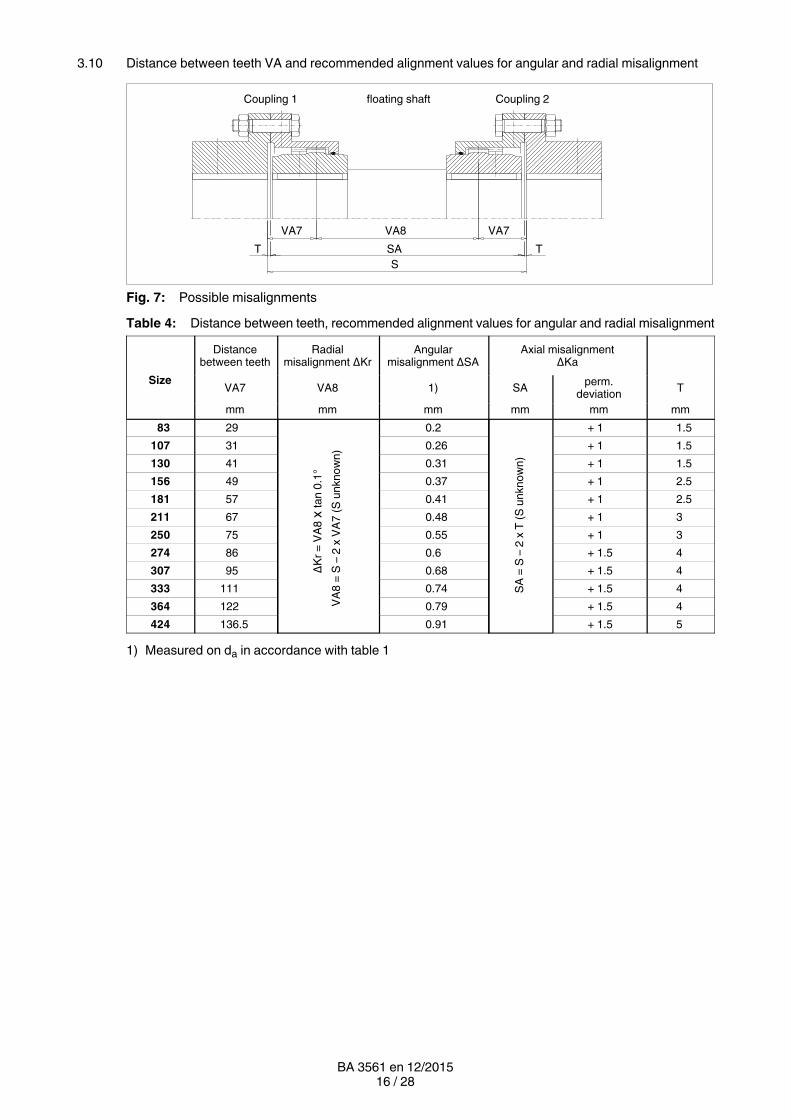
3.10 Distance between teeth VA and recommended alignment values for angular and radial misalignment
Coupling 1 Coupling 2floating shaft
VA7 VA7
SA
S
VA8
T T
Fig. 7: Possible misalignments
Table 4: Distance between teeth, recommended alignment values for angular and radial misalignment
Size
Distancebetween teeth
Radialmisalignment ΔKr
Angularmisalignment ΔSA
Axial misalignmentΔKa
VA7 VA8 1) SAperm.
deviationT
mm mm mm mm mm mm
83 29
ΔK
r =
VA
8 x
ta
n 0
.1°
VA
8 =
S –
2 x
VA
7 (
S u
nk
no
wn
)
0.2
SA
= S
– 2
x T
(S
un
kn
ow
n)
+ 1 1.5
107 31 0.26 + 1 1.5
130 41 0.31 + 1 1.5
156 49 0.37 + 1 2.5
181 57 0.41 + 1 2.5
211 67 0.48 + 1 3
250 75 0.55 + 1 3
274 86 0.6 + 1.5 4
307 95 0.68 + 1.5 4
333 111 0.74 + 1.5 4
364 122 0.79 + 1.5 4
424 136.5 0.91 + 1.5 5
1) Measured on da in accordance with table 1

17 / 28BA 3561 en 12/2015
3.11 Distance dimensions "S"
Table 5: Distance dimensions "S4" and "S10"
Size
perm. deviation
Size
perm. deviation
S10 S4 S4, S10 S10 S4 S4, S10
mm mm mm mm mm mm
83 3 12 + 0.5 250 6 24 + 0.5
107 3 9 + 0.5 274 8 29 + 0.75
130 3 17 + 0.5 307 8 32 + 0.75
156 5 17 + 0.5 333 8 39 + 0.75
181 5 19 + 0.5 364 8 46 + 0.75
211 6 23 + 0.5 424 10 43 + 0.75
3.12 Assignment of the tightening torques and wrench widths
The use of an impact screwdriver is not permissible!
Tightening torques apply to bolts with untreated surfaces which are not or only lightly oiled (coefficient offriction μ = 0.14). The use of lubricant paint or lubricant, which affects the coefficient of friction "μ", is notpermitted.
The specified tightening torques TA must be complied with, applying DIN 25202 ScrewConnectionClass "C", with an outputtorque scatter of ± 5 %.
The tightening torques and wrench widths of the set screws are specified in table 3.
Table 6: Tightening torques and wrench widths of the parts 6 and 9
Size
Tightening torques TA Wrench width SW
for bolts of the strength class 8.8 to DIN ISO 898 Part 1(with μ = 0.14)
Hexagonsocket
Hexagonhead
Part no. 9 Part no. 6 Part no. 9
Nm mm mm
83 25 3 13
107 49 5 17
130 49 5 17
156 86 5 19
181 86 5 19
211 210 5 24
250 210 5 24
274 210 5 24
307 410 5 30
333 410 5 30
364 410 5 30
424 710 5 36

18 / 28BA 3561 en 12/2015
4. Startup and operation
4.1 Requirements for grease
For ZAPEX couplings of series ZN.., only greases containing active agents for increasing corrosionprotection and resistance to ageing and for reducing wear in mixedfriction areas are approved.
• Greases must have been manufactured on the base of mineral oil.
• Viscosity class for greases: DIN 51818, NLGI 0, NLGI 00.
• Suitablity for sealing rings made of elastomer materials NBR and FPM.
• Compatibility with liquid seals: LOCTITE 5910, 5922
Lubricants must never be mixed with other substances.Before mixing different types of lubricants always ask the manufacturer on thecompatibility of the lubricants.
4.2 Recommended lubricants
The following lubricant recommendations apply to the ZAPEX couplings described in these instructions:
Table 7: Lubricants
Lubricant
performance
Liquefied greases FDP 00EnergreaseLS‐EP 00
Tribol 3020/1000‐00◆ Longtime PD 00
FLENDERHochleistungsfett
Lubricant
Liquefied greasesRENOLIT
SO‐D 6024GRAFLOSCONC‐SG 500 Plus
Mobilux EP 004 Alvania GL 00
The lubricants are suitable for operating temperatures of between 20 °C and + 80 °C.
◆ Lubricants with this mark are suitable for operating temperatures of between 40 °C and + 80 °C.
Observe manufacturer's instructions for handling lubricants!
19 / 28BA 3561 en 12/2015
4.3 Grease quantity
If the grease-filling quantity is not in accordance with the specified quantity, thecoupling may become an explosion hazard.
Table 8: Grease quantities
Size
Greasequantity
Size
Greasequantity
Size
Greasequantity
per coupling per coupling per coupling
dm3 dm3 dm3
83 0.02 181 0.17 307 0.7
107 0.04 211 0.21 333 0.9
130 0.08 250 0.35 364 1.15
156 0.1 274 0.45 424 1.5
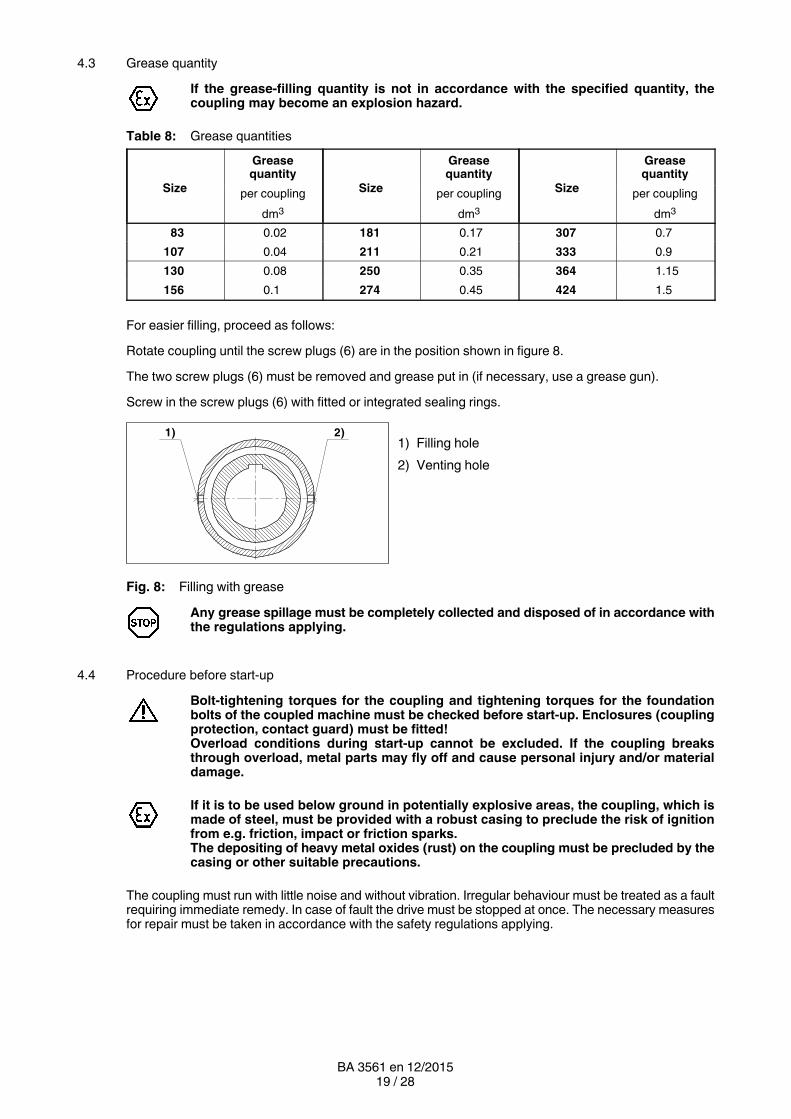
For easier filling, proceed as follows:
Rotate coupling until the screw plugs (6) are in the position shown in figure 8.
The two screw plugs (6) must be removed and grease put in (if necessary, use a grease gun).
Screw in the screw plugs (6) with fitted or integrated sealing rings.
1) Filling hole
2) Venting hole
Fig. 8: Filling with grease
Any grease spillage must be completely collected and disposed of in accordance withthe regulations applying.
4.4 Procedure before startup
Bolttightening torques for the coupling and tightening torques for the foundationbolts of the coupled machine must be checked before startup. Enclosures (couplingprotection, contact guard) must be fitted!Overload conditions during startup cannot be excluded. If the coupling breaksthrough overload, metal parts may fly off and cause personal injury and/or materialdamage.
If it is to be used below ground in potentially explosive areas, the coupling, which ismade of steel, must be provided with a robust casing to preclude the risk of ignitionfrom e.g. friction, impact or friction sparks.The depositing of heavy metal oxides (rust) on the coupling must be precluded by thecasing or other suitable precautions.
The coupling must run with little noise and without vibration. Irregular behaviour must be treated as a faultrequiring immediate remedy. In case of fault the drive must be stopped at once. The necessary measuresfor repair must be taken in accordance with the safety regulations applying.
2)1)

20 / 28BA 3561 en 12/2015
5. Faults, causes and remedy
5.1 Possible cause of fault
Change in alignment:
─ Rectify the cause of the change in alignment (e.g. loose foundation bolts).
─ Align the coupling.
─ Check the axial fastening and, if necessary, adjust.
Insufficient lubricant:
─ Take a small grease sample at the screw plug (6) and check, whether the grease can still be used. Ifthe consistence of the grease has changed, the grease should be changed as described in item 6.2.
─ In case of leakage the lost grease quantity must be recharged, or the grease should be changed asdescribed in item 6.2. In case of a complet grease change as described in item 6.2, the sealingrings (12) should also be replaced, as described in item 6.3.
5.2 Incorrect use
Failure to observe these instructions may result in breakage of the coupling.Danger from flying fragments!Through incorrect use the coupling may become an explosion hazard.
5.2.1 Frequent faults when selecting the coupling and/or coupling size
• Important information for describing the drive and the environment are not communicated.
• System torque too high.
• System speed too high.
• Application factor not correctly selected.
• Chemically aggressive environment not taken into consideration.
• The ambient temperature is not permissible.
• Finished bore with inadmissible diameter and/or inadmissible assigned fits.
• Machining of parallel keyways of which the width across corners is greater than the width acrosscorners of the parallel keyways to DIN 6885/1 with a maximum permissible bore.
• The transmission capacity of the shafthub connection is not appropriate to the operating conditions.
• Maximum load or overload conditions are not being taken into consideration.
• Dynamic load conditions are not being taken into consideration.
• Shafthub connection resulting in impermissible material stress on the coupling.
• Operating conditions are being changed without authorisation.
• Coupling and machine or drive train form a critical torsional, axial or bending vibration system.
• Fatigue torque load too high.

21 / 28BA 3561 en 12/2015
5.2.2 Frequent faults when fitting the coupling
• Components with transport or other damage are being fitted.
• When fitting coupling parts in a heated condition, sealing rings are being excessively heated.
• The shaft diameter is beyond the specified tolerance range.
• Coupling parts are being interchanged, i.e. their assignment to the specified shaft is incorrect.
• Specified axial fastenings are not fitted.
• Specified tightening torques are not being adhered to.
• Bolts are inserted dry or greased.
• Flange surfaces of screwed connections have not been cleaned.
• Alignment and/or shaftmisalignment values do not match the specifications in the instructions manual.
• The coupled machines are not correctly fastened to the foundation, and as a result shifting of themachines e.g. through loosening of the foundationscrew connection is causing excessivedisplacement of the coupling parts.
• The coupled machines are not sufficiently earthed.
• Sealing rings are not fitted.
• Sealing surfaces are being painted.
• The lubricant has not been correctly put in (see section 4).
• The back clearance of the parallel key has not been filled with sealing compound (when inserting theset screw no sealing compound has been put into the threaded hole).
• The coupling guard used is not suitable.
5.2.3 Frequent faults in maintenance
• Maintenance intervals are not being adhered to.
• No genuine ZAPEX spare parts are being used.
• Old or damaged ZAPEX spare parts are being used.
• Leakage in the vicinity of the coupling is not being identified and as a result chemically aggressivemedia are damaging the coupling.
• Fault indications (noise, vibrations, etc.) are not being observed.
• Specified tightening torques are not being adhered to.
• Alignment and/or shaftmisalignment values do not match the specifications in the instructions manual.
6. Maintenance and repair
6.1 General
The coupling must be checked for heating and any change in the noise level at general maintenanceintervals or at least every three months.
The coupling must run with little noise and without vibration in all operating phases. Irregular behaviourmust be treated as a fault requiring immediate remedy.

22 / 28BA 3561 en 12/2015
6.2 Changing grease
During the regular inspections the coupling must be checked for leaks.
If the grease filling quantity is not in accordance with the specified quantity, thecoupling may become an explosion hazard.
Change lubricant:
─ When used at max. 70 °C: after approx. 8000 operating hours, at the latest after 2 years.
─ When used at temperature above 70 °C: after approx. 3000 operating hours, at the latest after 1 year.
When changing lubricant of the same type, the quantity of lubricant remaining in the coupling should bekept as low as possible. Generally speaking, a small residual quantity will cause no particular problems.Lubricants of different types and manufacturers must not be mixed together. If necessary, confirmationthat the new lubricant is compatible with residues of the old lubricant should be obtained from themanufacturer.
Unscrew screw plugs (6) and drain off the grease into a suitable vessel, as shown in the diagram. Tofacilitate the process, add lowviscosity oil to the used grease and mix. Observe compatibility of the oilwith the grease!
All the grease must be completely collected and disposed of in accordance with theregulations applying.
1) Venting hole
2) Drain hole
Fig. 9: Changing grease
Fill with grease (see section 4).
6.3 Replacing Orings
The grease must be drained off as described in item 6.2.
The Orings (12) can be replaced with openended (cut) Orings (12), while adhering to dimensions "Q"and "P" (see section 1 "Technical Data"), without having to move the machines to be connected.
For this, undo the screw connection (8; 9) of the flanged sleeves (5) or coupling parts 3 (3) and push theflanged sleeves (5) off the teeth and far enough off the hub for the Orings (12) to be able to be removed.
Clean sealing compound off the flanged sleeves (5) or coupling parts 3 (3).
Cut the new Oring (12) through radially at one point, place it over the hub and glue the cut ends exactlytogether. Adhesive e.g. LOCTITE 401.
Then place the cut section into the groove and, working from there, insert the Oring (12) from both sides.
Smear the sealing surfaces of the flanged sleeves (5) or coupling part (3) with sealing compound and boltthem together (for tightening torques, see section 3, item 3.12).
Fill with grease (see section 4).
1)
2)

23 / 28BA 3561 en 12/2015
6.4 Demounting the coupling
The grease must be drained off as described in item 6.2.
Retain the floating shaft (4) with the fitted coupling parts 1 (1) and the flanged sleeves (5) using suitablelifting gear, loosen the fittingbolt connection (8; 9) on both sides and remove the assembly.
The flanged sleeves (5) must be pushed off the teeth and supported above the floating shaft (4) behindthe coupling parts 1 (1).
Examine the teeth, the sealings (12) and the sealing surfaces for damage. Damaged parts must bereplaced.
For reassembly, the instructions in sections 3 and 4 must be observed.
6.5 Demounting the coupling parts (1; 3) in case of shafthub connection with parallel key
Remove the axial fastening (set screw, end plate). Mount a suitable detaching device. Using a burner, heatcoupling part (1; 3) along its length and above the parallel keyway (max. + 80 °C).
Burner an heated coupling parts form an explosion hazard, therefor there must not bean explosible atmosphere when fitting the coupling parts.
Pull the coupling part off. Examine the teeth, the sealing surfaces, the hub bore and the shaft for damageand protect against rust. Damaged parts must be replaced.
For reassembly, the instructions in sections 3 and 4 must be observed.
6.6 Demounting the coupling parts (1; 3) in case of cylindrical and tapered interference fit set up foroilhydraulic shrinkingoff
For demounting the following tools are needed:
• For each oil channel (for number, see the dimensioned drawing) an oil pump with pressure gauge(min. 2 500 bar) or a motor pump with corresponding number of independently closable connectionsIn case of coupling parts (1; 3) with stepped bore, a motordriven pump must be connected up to theoil channel located at the point of transition from the smaller bore to the larger, as a large quantity of oilper unit of time is needed here.
• Suitable connections and pipes.
• 1 detaching device or retaining plate with retaining screws or threaded spindles with nuts (material ofscrews and spindles min. 10.9, material of nuts identical to that of the screws).
• 1 hydraulic cylinder with oil pump. Note displacement and pressure of the hydraulic cylinder (for axialforce, consult Siemens or refer to the dimensioned drawing).
Observe manufacturer's instructions for using the detaching device and pumps.
Before detaching the coupling part (1; 3) the detaching device must be fitted as shown in the figure.

24 / 28BA 3561 en 12/2015
6.6.1 Demounting the coupling parts (1; 3) in case of cylindrical interference fit
1) Retaining plate
2) Threaded spindle
3) Shaft
4) Hydraulic cylinder
5) Screw plug (22)
Fig. 10: Demounting the coupling parts (1; 3) in case of cylindrical interference fit
Secure coupling part (1; 3) and detaching device, using suitable equipment!
The screw plugs (22) must be removed from the oil channels. An oil pump must be bled and connectedup to the middle oil channel (here oil channel I).
Then the pump must be operated at the pressure specified on the dimensioned drawing until oil emergesfrom the adjacent connections (oil channels IV and II).
The max. pressure specified on the dimensioned drawing must not be exceeded.During the entire operation the pressure must be maintained at a constant level on allthe oil channels to which pressure is applied.
Bleed the next oil pump, connect it to oil channel II and operate it at the pressure specified on thedimensioned drawing until the oil emerges at oil channel III.
Bleed the next oil pump, connect it to oil channel IV and operate it at the pressure specified on thedimensioned drawing until a ring of oil emerges at the end face.
Bleed the next oil pump, connect it up to oil channel III and operate it at the pressure specified on thedimensioned drawing until a ring of oil emerges at the end face.
If, when pressure is applied, oil emerges to the extent that pressure cannot be maintained, a thicker oil mustbe specified.
Only when an unbroken ring of oil emerges from both end faces can pressure be applied to the hydrauliccylinder to slide the coupling part (1; 3) smartly off the shaft.
All the oil must be completely collected and disposed of in accordance with the regulations applying.
Note stroke of hydraulic cylinder. If readjustment is necessary, the end face of thehydraulic cylinder must stop between 2 oil channels.
After detaching, the oil pumps and the detaching device must be removed from the coupling part (1; 3).
Examine the teeth, the sealing surfaces, the hub bore and the shaft for damage and protect against rust.Damaged parts must be replaced.
For reassembly, the instructions in sections 3 and 4 must be observed.
4)
I IIIV III1) 2) 3)5)

25 / 28BA 3561 en 12/2015
6.6.2 Demounting the coupling parts (1; 3) in case of tapered interference fit
1) Retaining plate
2) Threaded spindle
3) Shaft
4) Hydraulic cylinder
5) Screw plug (22)
6) Eye nut
7) Inspection window
8) Stroke
Fig. 11: Demounting the coupling parts (1; 3) in case of tapered interference fit
Secure coupling part (1; 3) and detaching device, using suitable equipment! Toprevent the coupling part (1; 3) from suddenly coming off, it must be secured axially(as shown in figure 11).
The screw plugs (22) must be removed from the oil channels.
Sufficient pressure must be applied to the hydraulic cylinder for it to generate at least the axial forcespecified on the dimensioned drawing.
The oil pump must be bled, connected up to oil channel I and operated at the pressure indicated on thedimensioned drawing until a ring of oil emerges at the end face or from the adjacent connection.
The maximum pressure specified on the dimensioned drawing must not be exceeded.
If, when pressure is applied, oil emerges to the extent that pressure cannot be maintained, a thicker oil mustbe specified.
The pressure must be maintained until a ring of oil emerges at both end faces. This must be monitoredthrough the inspection window at the side of the detaching device.
All the oil must be completely collected and disposed of in accordance with the regulations applying.
Only when an unbroken ring of oil emerges from both end faces can the hydraulic cylinder be bled. Thecoupling part (1; 3) slides off the shaft until there is no adhesion between the coupling part (1; 3) and theshaft.
Detach the oil pump and detaching device. Remove coupling part (1; 3).
Examine the teeth, the sealing surfaces, the hub bore and the shaft for damage and protect against rust.Damaged parts must be replaced.
For reassembly, the instructions in sections 3 and 4 must be observed.
3)5)
8)
4)
I1)
6)
2)
7)

26 / 28BA 3561 en 12/2015
7. Stocking spare parts
7.1 Spare parts
For ordering spare parts state the following data, as far as possible:
• Siemens order number and position
• Drawing number
• Coupling type and coupling size
• Part numer (see spareparts list)
• Bore, bore tolerance, keyway and balancing as well as particular characteristics such asflangeconnection dimensions, floatingshaft length, brakedrum dimensions.
• Any special details such as temperature, electrically insulating.
16 53 9 8 12
(7)
426
1) 2) 3)
26 1 12 5 8 6
(7)
9 3
Fig. 12: Spareparts drawing
1) Coupling 1 2) floating shaft 3) Coupling 2
Table 9: Spareparts list
Partnumber
DesignationPart
numberDesignation
1 Coupling part 1 8 Close-fitting bolt
3 Coupling part 3 9 Hexagon nut
4 Floating shaft 12 O-ring
5 Flanged sleeve 22 Screw plug 2)
6 Screw plug 26 Parallel key
7 Sealing ring 1) 50 Sealing compound
1) The sealing ring (7) is provided only on size 83. On the other sizes the sealing ring is integrated into thescrew plug (6).
2) The screw plugs (22) are used only with an hydraulic interference fit (see section 6, items 6.6.1and 6.6.2).
22
Fig. 13: Screw plug

27 / 28BA 3561 en 12/2015
8. Declarations
8.1 EU declaration of conformity
EU declaration of conformity
The manufacturer, Siemens AG, 46395 Bocholt, Germany, declares that the equipment described in theseoperating instructions:
FLENDER ZAPEX®couplingsType ZNW
is in conformity with Article 1 and Article 13, Paragraph 1 b) ii) of Directive 2014/34/EU and complies with therequirements of Directive 2014/34/EU and the following standards:
EN 1127-1 : 2011EN 13463‐1 : 2009EN 13463‐5 : 2011
This declaration of conformity is issued under the sole responsibility of the manufacturer.
The object of the declaration described above is in conformity with the relevant Union harmonisationlegislation:
Directive 2014/34/EU OJ L 96, 29.03.2014, p.309-356 (effective from 20.04.2016, 00:00 a.m.)
Directive 94/9/EC OJ L 100, 19.04.1994, p.1-29 (effective until 19.04.2016, 12.00 p.m.)
The technical documentation has been delivered to the body named below:
DEKRA EXAM GmbH, 44727 Bochum, Germany, code number: 0158.
Bocholt, 2015‐12‐14Nicola Warning / Head of PD MD AP COU
Bocholt, 2015‐12‐14Thomas Tebrügge / Head of PD MD AP COU BA

Siemens AGIndustry SectorMechanical DrivesAlfred-Flender-Straße 7746395 BocholtGERMANY
www.siemens.com/drivetechnologies
Subject to modifications
© Siemens AG 2011
Further Information:
"FLENDER gear units" on the Internetwww.siemens.com/gearunits
"FLENDER couplings" on the Internetwww.siemens.com/couplings
Service & Support:http://support.automation.siemens.com/WW/view/en/10803928/133300
Lubricants:http://support.automation.siemens.com/WW/view/en/42961591/133000