flex system enterprise chassis - lenovo press · the flex system enterprise chassis is a simple,...
TRANSCRIPT
Flex System Enterprise ChassisProduct Guide
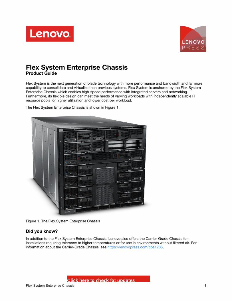
Flex System is the next generation of blade technology with more performance and bandwidth and far morecapability to consolidate and virtualize than previous systems. Flex System is anchored by the Flex SystemEnterprise Chassis which enables high-speed performance with integrated servers and networking.Furthermore, its flexible design can meet the needs of varying workloads with independently scalable ITresource pools for higher utilization and lower cost per workload.The Flex System Enterprise Chassis is shown in Figure 1.
Figure 1. The Flex System Enterprise Chassis
Did you know?In addition to the Flex System Enterprise Chassis, Lenovo also offers the Carrier-Grade Chassis forinstallations requiring tolerance to higher temperatures or for use in environments without filtered air. Forinformation about the Carrier-Grade Chassis, see https://lenovopress.com/tips1285.
Flex System Enterprise Chassis 1

Key featuresThe Flex System Enterprise Chassis is a simple, integrated infrastructure platform that supports a mix ofcompute, storage, and networking resources to meet the demands of your applications. The solution is easilyscalable with the addition of another chassis with the required nodes. With Lenovo XClarity Administrator,multiple chassis can be monitored from a single screen. This flexible 14 node, 10U chassis is designed for asimple deployment now and to scale to meet your needs in the future.Flexibility and efficiencyThe 14 bays in the chassis allow the installation of compute or management nodes, with networking modulesin the rear. A single chassis or a group of chassis can be fully customized to the specific needs of thecomputing environment. IT can meet the needs of the business using a single system across multipleoperating environments.The system monitors and manages power usage on all major chassis components so you have total controlover power consumption. Available power supply options are AC and -48V DC. AC power options can beconfigurable in either a single or three-phase power domain. The chassis supports N+N or N+1 redundantpower supplies and an entirely passive mid-plane to meet your reliability needs. The power supplies are 80PLUS Platinum-certified indicating high energy efficiency. The chassis design also optimizes cooling withcooling zones within the chassis. The system manages the fan modules based on node configuration withinthe chassis. So, the system can increase the speed of certain fan modules to cool potential hot spots, and uselower speeds for other fan modules where appropriate.Easily scalable with simple administrationBecause the Flex System Enterprise Chassis is an all-in-one solution, it is designed for growth from a singlechassis to many. Adding compute, or networking capability is as simple as adding additional nodes ormodules. Compute nodes and I/O modules connect to a midplane and are designed to be inserted orremoved while the chassis is running. The use of the midplane means that the compute nodes and I/Omodules do not need their own power cables and do not need network cables or transceivers to connect toeach other within the chassis. These features make it easy to add or replace compute nodes and get themoperational quickly.The simple, highly integrated management system allows you to use the Chassis Management Modulesintegrated into each chassis to administer a single chassis, and the new Lenovo XClarity Administrator offersagent-free hardware management for compute nodes and networking.Designed for multiple generations of technologyThe Flex System Enterprise Chassis is designed to be the foundation of your IT infrastructure now and intothe future. Compute performance requirements are always on the rise and networking demands continue togrow with rising bandwidth needs and a shrinking tolerance for latency. The chassis is designed to scale tomeet the needs of your future workloads, offering the flexibility to support current and future innovations incompute, storage, and networking technology.
Locations of key components and connectorsFlex System Enterprise Chassis 2
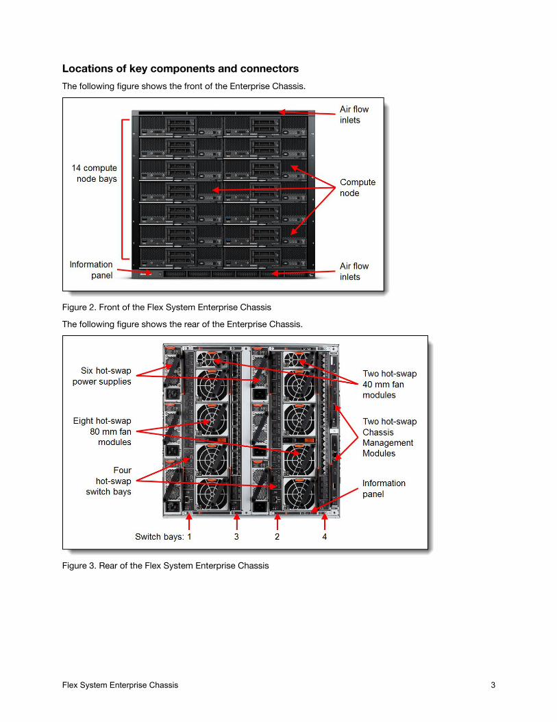
Locations of key components and connectorsThe following figure shows the front of the Enterprise Chassis.
Figure 2. Front of the Flex System Enterprise ChassisThe following figure shows the rear of the Enterprise Chassis.
Figure 3. Rear of the Flex System Enterprise Chassis
Flex System Enterprise Chassis 3
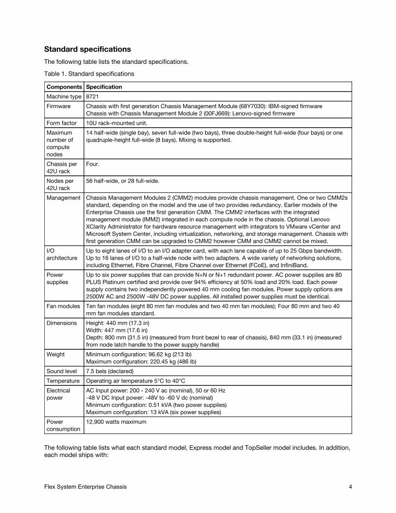
Standard specificationsThe following table lists the standard specifications.Table 1. Standard specifications
Components SpecificationMachine type 8721Firmware Chassis with first generation Chassis Management Module (68Y7030): IBM-signed firmware
Chassis with Chassis Management Module 2 (00FJ669): Lenovo-signed firmwareForm factor 10U rack-mounted unit.Maximumnumber ofcomputenodes
14 half-wide (single bay), seven full-wide (two bays), three double-height full-wide (four bays) or onequadruple-height full-wide (8 bays). Mixing is supported.
Chassis per42U rack
Four.
Nodes per42U rack
56 half-wide, or 28 full-wide.
Management Chassis Management Modules 2 (CMM2) modules provide chassis management. One or two CMM2sstandard, depending on the model and the use of two provides redundancy. Earlier models of theEnterprise Chassis use the first generation CMM. The CMM2 interfaces with the integratedmanagement module (IMM2) integrated in each compute node in the chassis. Optional LenovoXClarity Administrator for hardware resource management with integrators to VMware vCenter andMicrosoft System Center, including virtualization, networking, and storage management. Chassis withfirst generation CMM can be upgraded to CMM2 however CMM and CMM2 cannot be mixed.
I/Oarchitecture
Up to eight lanes of I/O to an I/O adapter card, with each lane capable of up to 25 Gbps bandwidth.Up to 16 lanes of I/O to a half-wide node with two adapters. A wide variety of networking solutions,including Ethernet, Fibre Channel, Fibre Channel over Ethernet (FCoE), and InfiniBand.
Powersupplies
Up to six power supplies that can provide N+N or N+1 redundant power. AC power supplies are 80PLUS Platinum certified and provide over 94% efficiency at 50% load and 20% load. Each powersupply contains two independently powered 40 mm cooling fan modules. Power supply options are2500W AC and 2500W -48V DC power supplies. All installed power supplies must be identical.
Fan modules Ten fan modules (eight 80 mm fan modules and two 40 mm fan modules); Four 80 mm and two 40mm fan modules standard.
Dimensions Height: 440 mm (17.3 in)Width: 447 mm (17.6 in)Depth: 800 mm (31.5 in) (measured from front bezel to rear of chassis), 840 mm (33.1 in) (measuredfrom node latch handle to the power supply handle)
Weight Minimum configuration: 96.62 kg (213 lb)Maximum configuration: 220.45 kg (486 lb)
Sound level 7.5 bels (declared)Temperature Operating air temperature 5°C to 40°CElectricalpower
AC Input power: 200 - 240 V ac (nominal), 50 or 60 Hz-48 V DC Input power: -48V to -60 V dc (nominal)Minimum configuration: 0.51 kVA (two power supplies)Maximum configuration: 13 kVA (six power supplies)
Powerconsumption
12,900 watts maximum
The following table lists what each standard model, Express model and TopSeller model includes. In addition,each model ships with:
Flex System Enterprise Chassis 4
One C19 to C20 two-meter power cable for each power supplyOne Rack Mount Kit
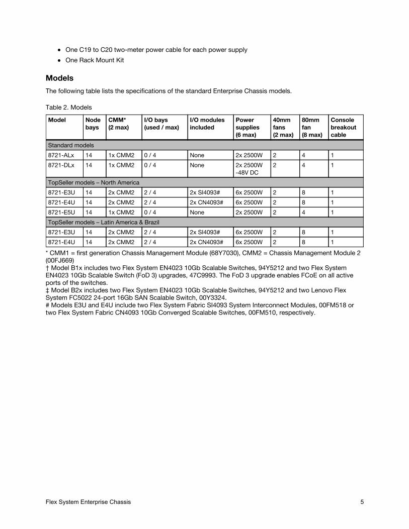
ModelsThe following table lists the specifications of the standard Enterprise Chassis models.
Table 2. ModelsModel Node
baysCMM*(2 max)
I/O bays(used / max)
I/O modulesincluded
Powersupplies(6 max)
40mmfans(2 max)
80mmfan(8 max)
Consolebreakoutcable
Standard models8721-ALx 14 1x CMM2 0 / 4 None 2x 2500W 2 4 18721-DLx 14 1x CMM2 0 / 4 None 2x 2500W
-48V DC2 4 1
TopSeller models – North America8721-E3U 14 2x CMM2 2 / 4 2x SI4093# 6x 2500W 2 8 18721-E4U 14 2x CMM2 2 / 4 2x CN4093# 6x 2500W 2 8 18721-E5U 14 1x CMM2 0 / 4 None 2x 2500W 2 4 1TopSeller models – Latin America & Brazil8721-E3U 14 2x CMM2 2 / 4 2x SI4093# 6x 2500W 2 8 18721-E4U 14 2x CMM2 2 / 4 2x CN4093# 6x 2500W 2 8 1
* CMM1 = first generation Chassis Management Module (68Y7030), CMM2 = Chassis Management Module 2(00FJ669)† Model B1x includes two Flex System EN4023 10Gb Scalable Switches, 94Y5212 and two Flex SystemEN4023 10Gb Scalable Switch (FoD 3) upgrades, 47C9993. The FoD 3 upgrade enables FCoE on all activeports of the switches.‡ Model B2x includes two Flex System EN4023 10Gb Scalable Switches, 94Y5212 and two Lenovo FlexSystem FC5022 24-port 16Gb SAN Scalable Switch, 00Y3324.# Models E3U and E4U include two Flex System Fabric SI4093 System Interconnect Modules, 00FM518 ortwo Flex System Fabric CN4093 10Gb Converged Scalable Switches, 00FM510, respectively.
Flex System Enterprise Chassis 5
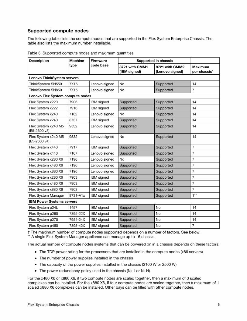
Supported compute nodesThe following table lists the compute nodes that are supported in the Flex System Enterprise Chassis. Thetable also lists the maximum number installable.
Table 3. Supported compute nodes and maximum quantitiesDescription Machine
typeFirmwarecode base
Supported in chassis8721 with CMM1(IBM signed)
8721 with CMM2(Lenovo signed)
Maximumper chassis*
Lenovo ThinkSystem serversThinkSystem SN550 7X16 Lenovo signed No Supported 14ThinkSystem SN850 7X15 Lenovo signed No Supported 7Lenovo Flex System compute nodesFlex System x220 7906 IBM signed Supported Supported 14Flex System x222 7916 IBM signed Supported Supported 14Flex System x240 7162 Lenovo signed No Supported 14Flex System x240 8737 IBM signed Supported Supported 14Flex System x240 M5(E5-2600 v3)
9532 Lenovo signed Supported Supported 14
Flex System x240 M5(E5-2600 v4)
9532 Lenovo signed No Supported 14
Flex System x440 7917 IBM signed Supported Supported 7Flex System x440 7167 Lenovo signed Supported Supported 7Flex System x280 X6 7196 Lenovo signed No Supported 7Flex System x480 X6 7196 Lenovo signed Supported Supported 7Flex System x880 X6 7196 Lenovo signed Supported Supported 7Flex System x280 X6 7903 IBM signed Supported Supported 7Flex System x480 X6 7903 IBM signed Supported Supported 7Flex System x880 X6 7903 IBM signed Supported Supported 7Flex System Manager 8731-A1x IBM signed Supported Supported 1**IBM Power Systems serversFlex System p24L 1457 IBM signed Supported No 14Flex System p260 7895-22X IBM signed Supported No 14Flex System p270 7954-24X IBM signed Supported No 14Flex System p460 7895-42X IBM signed Supported No 7
† The maximum number of compute nodes supported depends on a number of factors. See below.** A single Flex System Manager appliance can manage up to 16 chassisThe actual number of compute nodes systems that can be powered on in a chassis depends on these factors:
The TDP power rating for the processors that are installed in the compute nodes (x86 servers)The number of power supplies installed in the chassisThe capacity of the power supplies installed in the chassis (2100 W or 2500 W)The power redundancy policy used in the chassis (N+1 or N+N)
For the x480 X6 or x880 X6, if two compute nodes are scaled together, then a maximum of 3 scaledcomplexes can be installed. For the x880 X6, if four compute nodes are scaled together, then a maximum of 1scaled x880 X6 complexes can be installed. Other bays can be filled with other compute nodes.
Flex System Enterprise Chassis 6
The table in the Power Supplies section provides guidelines about what number of compute nodes can bepowered on in the Enterprise Chassis, based on the type and number of power supplies installed.See ServerProven® for the latest information about the supported servers:http://www.lenovo.com/us/en/serverproven/flexsystem.shtml
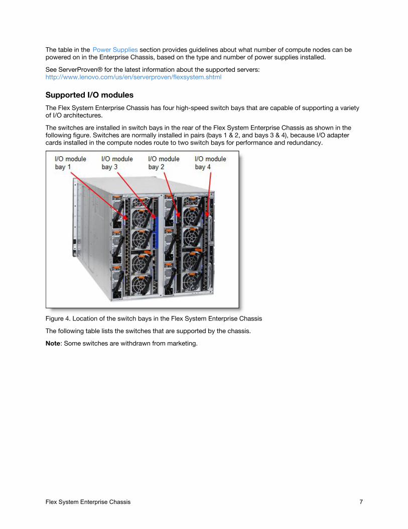
Supported I/O modulesThe Flex System Enterprise Chassis has four high-speed switch bays that are capable of supporting a varietyof I/O architectures.The switches are installed in switch bays in the rear of the Flex System Enterprise Chassis as shown in thefollowing figure. Switches are normally installed in pairs (bays 1 & 2, and bays 3 & 4), because I/O adaptercards installed in the compute nodes route to two switch bays for performance and redundancy.
Figure 4. Location of the switch bays in the Flex System Enterprise ChassisThe following table lists the switches that are supported by the chassis.Note: Some switches are withdrawn from marketing.
Flex System Enterprise Chassis 7
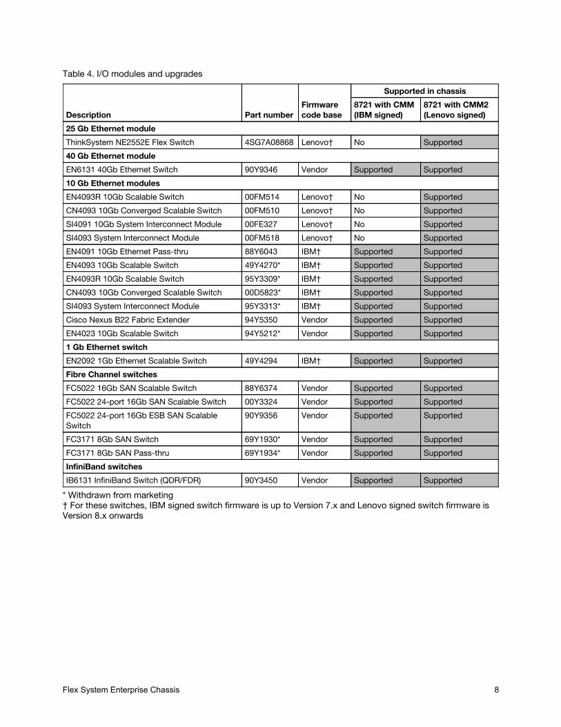
Table 4. I/O modules and upgrades
Description Part numberFirmwarecode base
Supported in chassis8721 with CMM(IBM signed)
8721 with CMM2(Lenovo signed)
25 Gb Ethernet moduleThinkSystem NE2552E Flex Switch 4SG7A08868 Lenovo† No Supported40 Gb Ethernet moduleEN6131 40Gb Ethernet Switch 90Y9346 Vendor Supported Supported10 Gb Ethernet modulesEN4093R 10Gb Scalable Switch 00FM514 Lenovo† No SupportedCN4093 10Gb Converged Scalable Switch 00FM510 Lenovo† No SupportedSI4091 10Gb System Interconnect Module 00FE327 Lenovo† No SupportedSI4093 System Interconnect Module 00FM518 Lenovo† No SupportedEN4091 10Gb Ethernet Pass-thru 88Y6043 IBM† Supported SupportedEN4093 10Gb Scalable Switch 49Y4270* IBM† Supported SupportedEN4093R 10Gb Scalable Switch 95Y3309* IBM† Supported SupportedCN4093 10Gb Converged Scalable Switch 00D5823* IBM† Supported SupportedSI4093 System Interconnect Module 95Y3313* IBM† Supported SupportedCisco Nexus B22 Fabric Extender 94Y5350 Vendor Supported SupportedEN4023 10Gb Scalable Switch 94Y5212* Vendor Supported Supported1 Gb Ethernet switchEN2092 1Gb Ethernet Scalable Switch 49Y4294 IBM† Supported SupportedFibre Channel switchesFC5022 16Gb SAN Scalable Switch 88Y6374 Vendor Supported SupportedFC5022 24-port 16Gb SAN Scalable Switch 00Y3324 Vendor Supported SupportedFC5022 24-port 16Gb ESB SAN ScalableSwitch
90Y9356 Vendor Supported Supported
FC3171 8Gb SAN Switch 69Y1930* Vendor Supported SupportedFC3171 8Gb SAN Pass-thru 69Y1934* Vendor Supported SupportedInfiniBand switchesIB6131 InfiniBand Switch (QDR/FDR) 90Y3450 Vendor Supported Supported
* Withdrawn from marketing† For these switches, IBM signed switch firmware is up to Version 7.x and Lenovo signed switch firmware isVersion 8.x onwards
Flex System Enterprise Chassis 8

I/O architectureEach half-wide compute node (such as the ThinkSystem SN550) has two adapter slots, and each full-widecompute node (such as the ThinkSystem SN850) has four adapter slots. The adapter slots in each computenode route through the chassis midplane to the switch bays. The architecture supports up to eight ports peradapter.The following figure shows how two-port adapters are connected to switches installed in the chassis.
Figure 5. Logical layout of the interconnects between two-port I/O adapters and I/O modulesA four-port adapter doubles the connections between each adapter and switch pair (for example, a four-portadapter in A1 in each compute node routes two connections to switch 1 and two connections to switch 2).The following figure shows how four-port adapters are connected to switches that are installed in the chassis.
Flex System Enterprise Chassis 9
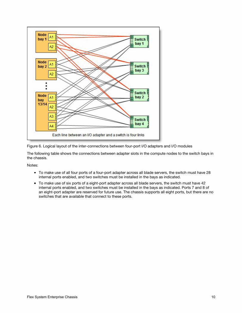
Figure 6. Logical layout of the inter-connections between four-port I/O adapters and I/O modulesThe following table shows the connections between adapter slots in the compute nodes to the switch bays inthe chassis.Notes:
To make use of all four ports of a four-port adapter across all blade servers, the switch must have 28internal ports enabled, and two switches must be installed in the bays as indicated.To make use of six ports of a eight-port adapter across all blade servers, the switch must have 42internal ports enabled, and two switches must be installed in the bays as indicated. Ports 7 and 8 ofan eight-port adapter are reserved for future use. The chassis supports all eight ports, but there are noswitches that are available that connect to these ports.
Flex System Enterprise Chassis 10
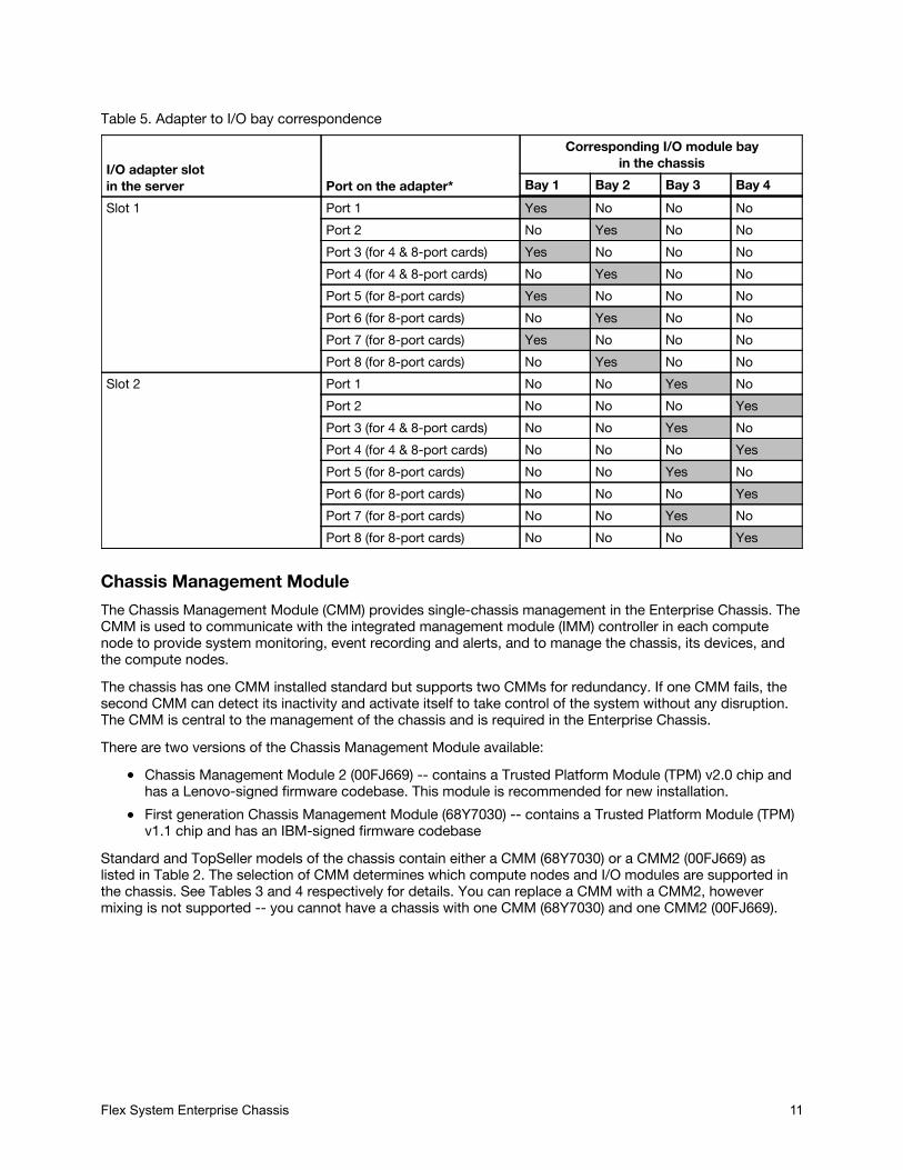
Table 5. Adapter to I/O bay correspondence
I/O adapter slotin the server Port on the adapter*
Corresponding I/O module bayin the chassis
Bay 1 Bay 2 Bay 3 Bay 4Slot 1 Port 1 Yes No No No
Port 2 No Yes No NoPort 3 (for 4 & 8-port cards) Yes No No NoPort 4 (for 4 & 8-port cards) No Yes No NoPort 5 (for 8-port cards) Yes No No NoPort 6 (for 8-port cards) No Yes No NoPort 7 (for 8-port cards) Yes No No NoPort 8 (for 8-port cards) No Yes No No
Slot 2 Port 1 No No Yes NoPort 2 No No No YesPort 3 (for 4 & 8-port cards) No No Yes NoPort 4 (for 4 & 8-port cards) No No No YesPort 5 (for 8-port cards) No No Yes NoPort 6 (for 8-port cards) No No No YesPort 7 (for 8-port cards) No No Yes NoPort 8 (for 8-port cards) No No No Yes
Chassis Management ModuleThe Chassis Management Module (CMM) provides single-chassis management in the Enterprise Chassis. TheCMM is used to communicate with the integrated management module (IMM) controller in each computenode to provide system monitoring, event recording and alerts, and to manage the chassis, its devices, andthe compute nodes.The chassis has one CMM installed standard but supports two CMMs for redundancy. If one CMM fails, thesecond CMM can detect its inactivity and activate itself to take control of the system without any disruption.The CMM is central to the management of the chassis and is required in the Enterprise Chassis.There are two versions of the Chassis Management Module available:
Chassis Management Module 2 (00FJ669) -- contains a Trusted Platform Module (TPM) v2.0 chip andhas a Lenovo-signed firmware codebase. This module is recommended for new installation.First generation Chassis Management Module (68Y7030) -- contains a Trusted Platform Module (TPM)v1.1 chip and has an IBM-signed firmware codebase
Standard and TopSeller models of the chassis contain either a CMM (68Y7030) or a CMM2 (00FJ669) aslisted in Table 2. The selection of CMM determines which compute nodes and I/O modules are supported inthe chassis. See Tables 3 and 4 respectively for details. You can replace a CMM with a CMM2, howevermixing is not supported -- you cannot have a chassis with one CMM (68Y7030) and one CMM2 (00FJ669).
Flex System Enterprise Chassis 11
The following table shows the ordering information.Table 6. Chassis Management Module
Partnumber
Feature codes* Description Standard / Maximum
68Y7030 A0TM / A0UE Flex System Chassis Management Module 1 / 200FJ669 ASPT / ASQ8 Flex System Chassis Management Module 2 1 / 2
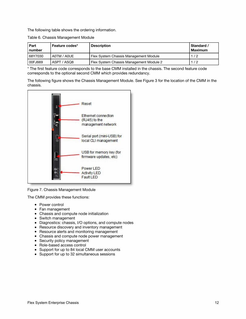
* The first feature code corresponds to the base CMM installed in the chassis. The second feature codecorresponds to the optional second CMM which provides redundancy.The following figure shows the Chassis Management Module. See Figure 3 for the location of the CMM in thechassis.
Figure 7. Chassis Management ModuleThe CMM provides these functions:
Power controlFan managementChassis and compute node initializationSwitch managementDiagnostics: chassis, I/O options, and compute nodesResource discovery and inventory managementResource alerts and monitoring managementChassis and compute node power managementSecurity policy managementRole-based access controlSupport for up to 84 local CMM user accountsSupport for up to 32 simultaneous sessions
Flex System Enterprise Chassis 12
The CMM has the following connectors:USB connection. This connection can be used for insertion of a USB media key for tasks, such asfirmware updates.10/100/1000 Mbps RJ45 Ethernet connection to connect to a management network. The CMM can bemanaged via this Ethernet port.Serial port (mini-USB) for local command-line interface (CLI) management. Use serial cable 90Y9338 forconnectivity.
The CMM has the following light-emitting diodes (LEDs) that provide the following information:Power-on LEDActivity LEDError LEDEthernet port link and port activity LEDs
The CMM also incorporates a reset button, which, when pressed, resets the CMM back to its defaultcondition. It has two functions, depending on how long the button is pressed:
When pressed for less than 5 seconds, the CMM restarts.When pressed for more than 5 seconds (for example, 10 or 15 seconds), the CMM configuration isreset to the manufacturing defaults, and then the CMM restarts.
The CMM supports a web-based graphical user interface (GUI) that provides a way to perform CMMfunctions within a supported web browser. You can also perform management functions through the CMMcommand-line interface (CLI). Both the web-based GUI and the CLI are accessible via the single RJ45Ethernet connector on the CMM or from any other system that is connected to the same (management)network.The CMM has the following default static IPv4 address. By default, the CMM is configured to respond toDynamic Host Configuration Protocol (DHCP) first before using its static IPv4 address:
IP address: 192.168.70.100Subnet: 255.255.255.0User ID: USERID (all capital letters)Password: PASSW0RD (all capital letters, with a zero instead of the letter O)
The CMM does not have a fixed static IPv6 IP address, by default. Initial access to the CMM in an IPv6environment can be performed by either using the IPv4 IP address or the IPv6 link-local address. The IPv6link-local address is automatically generated based on the Media Access Control (MAC) address of the CMM.The CMM is the key component enabling the integrated management network. Internally, the CMM has amultiple port L2 1Gigabit Ethernet switch with dedicated links to all 14 node bays, all four switch bays, andthe second CMM, if installed. These connections are all point-to-point, ensuring dedicated bandwidth. The1GbE links are full-duplex, fixed speed (not auto-negotiate) links. The 1 GbE management network is onlyaccessible by each node's management controller (IMMv2 or FSP), each switch module's managementinterfaces, the CMM, and the Flex System Manager (FSM) management appliance. This design permits theseparation of the management network from the data network.The CMM has a high-security policy that is enabled by default, which means that the following policies areenabled by default:
Strong password policies with automatic validation and verification checksRequired update of the default passwords after the initial setupOnly secure communication protocols, such as SSH and SSL. Unencrypted protocols, such as HTTP,Telnet, and SNMPv1, are disabled.Certificates to establish secure, trusted connections for applications that run on the managementprocessors
Lenovo XClarity AdministratorFlex System Enterprise Chassis 13
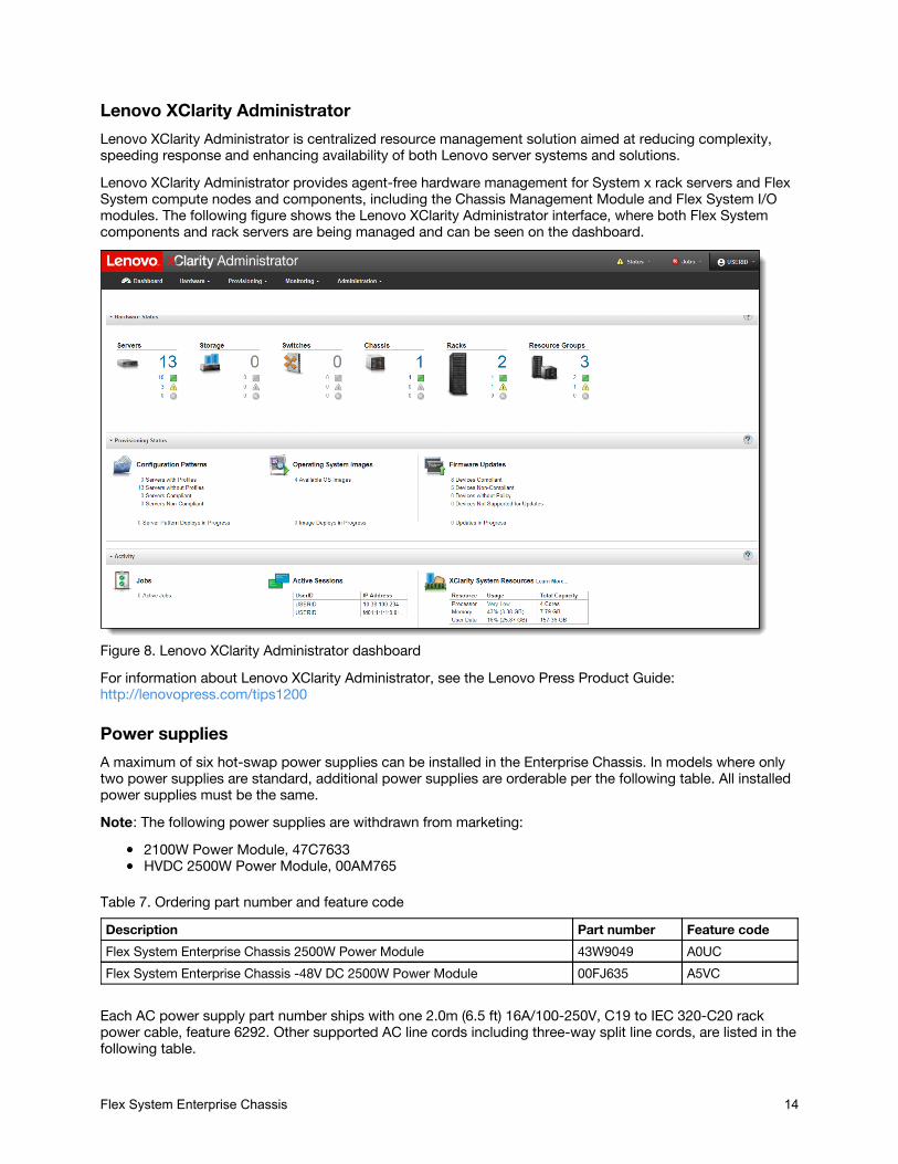
Lenovo XClarity AdministratorLenovo XClarity Administrator is centralized resource management solution aimed at reducing complexity,speeding response and enhancing availability of both Lenovo server systems and solutions.Lenovo XClarity Administrator provides agent-free hardware management for System x rack servers and FlexSystem compute nodes and components, including the Chassis Management Module and Flex System I/Omodules. The following figure shows the Lenovo XClarity Administrator interface, where both Flex Systemcomponents and rack servers are being managed and can be seen on the dashboard.
Figure 8. Lenovo XClarity Administrator dashboardFor information about Lenovo XClarity Administrator, see the Lenovo Press Product Guide:http://lenovopress.com/tips1200
Power suppliesA maximum of six hot-swap power supplies can be installed in the Enterprise Chassis. In models where onlytwo power supplies are standard, additional power supplies are orderable per the following table. All installedpower supplies must be the same.Note: The following power supplies are withdrawn from marketing:
2100W Power Module, 47C7633HVDC 2500W Power Module, 00AM765
Table 7. Ordering part number and feature codeDescription Part number Feature codeFlex System Enterprise Chassis 2500W Power Module 43W9049 A0UCFlex System Enterprise Chassis -48V DC 2500W Power Module 00FJ635 A5VC
Each AC power supply part number ships with one 2.0m (6.5 ft) 16A/100-250V, C19 to IEC 320-C20 rackpower cable, feature 6292. Other supported AC line cords including three-way split line cords, are listed in thefollowing table.
Flex System Enterprise Chassis 14
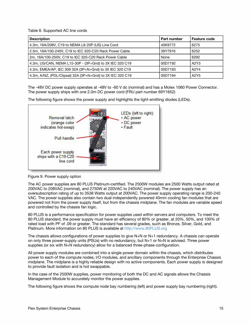
Table 8. Supported AC line cords
Description Part number Feature code4.3m, 16A/208V, C19 to NEMA L6-20P (US) Line Cord 40K9772 62752.5m, 16A/100-240V, C19 to IEC 320-C20 Rack Power Cable 39Y7916 62522m, 16A/100-250V, C19 to IEC 320-C20 Rack Power Cable None 62924.3m, US/CAN, NEMA L15-30P - (3P+Gnd) to 3X IEC 320 C19 00D7192 A2Y34.3m, EMEA/AP, IEC 309 32A (3P+N+Gnd) to 3X IEC 320 C19 00D7193 A2Y44.3m, A/NZ, (PDL/Clipsal) 32A (3P+N+Gnd) to 3X IEC 320 C19 00D7194 A2Y5
The -48V DC power supply operates at -48V to -60 V dc (nominal) and has a Molex 1060 Power Connector.The power supply ships with one 2.0m DC power cord (FRU part number 69Y1652)The following figure shows the power supply and highlights the light-emitting diodes (LEDs).
Figure 9. Power supply optionThe AC power supplies are 80 PLUS Platinum-certified. The 2500W modules are 2500 Watts output rated at200VAC to 208VAC (nominal), and 2750W at 220VAC to 240VAC (nominal). The power supply has anoversubscription rating of up to 3538 Watts output at 200VAC. The power supply operating range is 200-240VAC. The power supplies also contain two dual independently powered 40mm cooling fan modules that arepowered not from the power supply itself, but from the chassis midplane. The fan modules are variable speedand controlled by the chassis fan logic.80 PLUS is a performance specification for power supplies used within servers and computers. To meet the80 PLUS standard, the power supply must have an efficiency of 80% or greater, at 20%, 50%, and 100% ofrated load with PF of .09 or greater. The standard has several grades, such as Bronze, Silver, Gold, andPlatinum. More information on 80 PLUS is available at http://www.80PLUS.orgThe chassis allows configurations of power supplies to give N+N or N+1 redundancy. A chassis can operateon only three power-supply units (PSUs) with no redundancy, but N+1 or N+N is advised. Three powersupplies (or six with N+N redundancy) allow for a balanced three-phase configuration.All power supply modules are combined into a single power domain within the chassis, which distributespower to each of the compute nodes, I/O modules, and ancillary components through the Enterprise Chassismidplane. The midplane is a highly reliable design with no active components. Each power supply is designedto provide fault isolation and is hot swappable.In the case of the 2500W supplies, power monitoring of both the DC and AC signals allows the ChassisManagement Module to accurately monitor the power supplies.The following figure shows the compute node bay numbering (left) and power supply bay numbering (right).
Flex System Enterprise Chassis 15
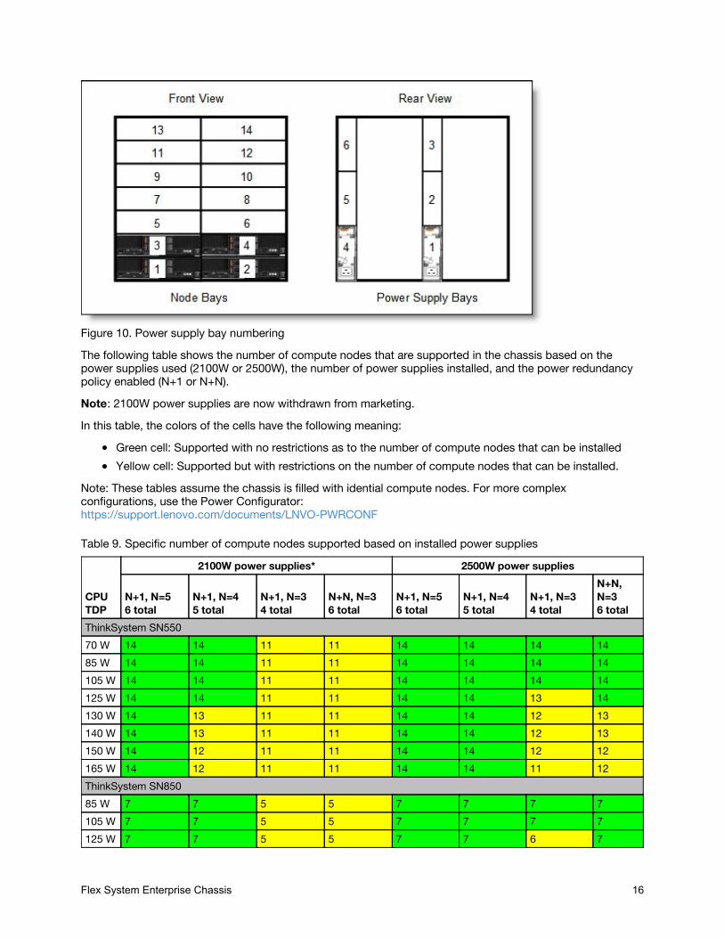
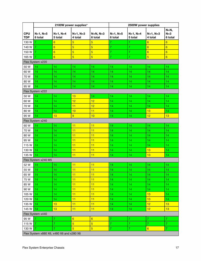
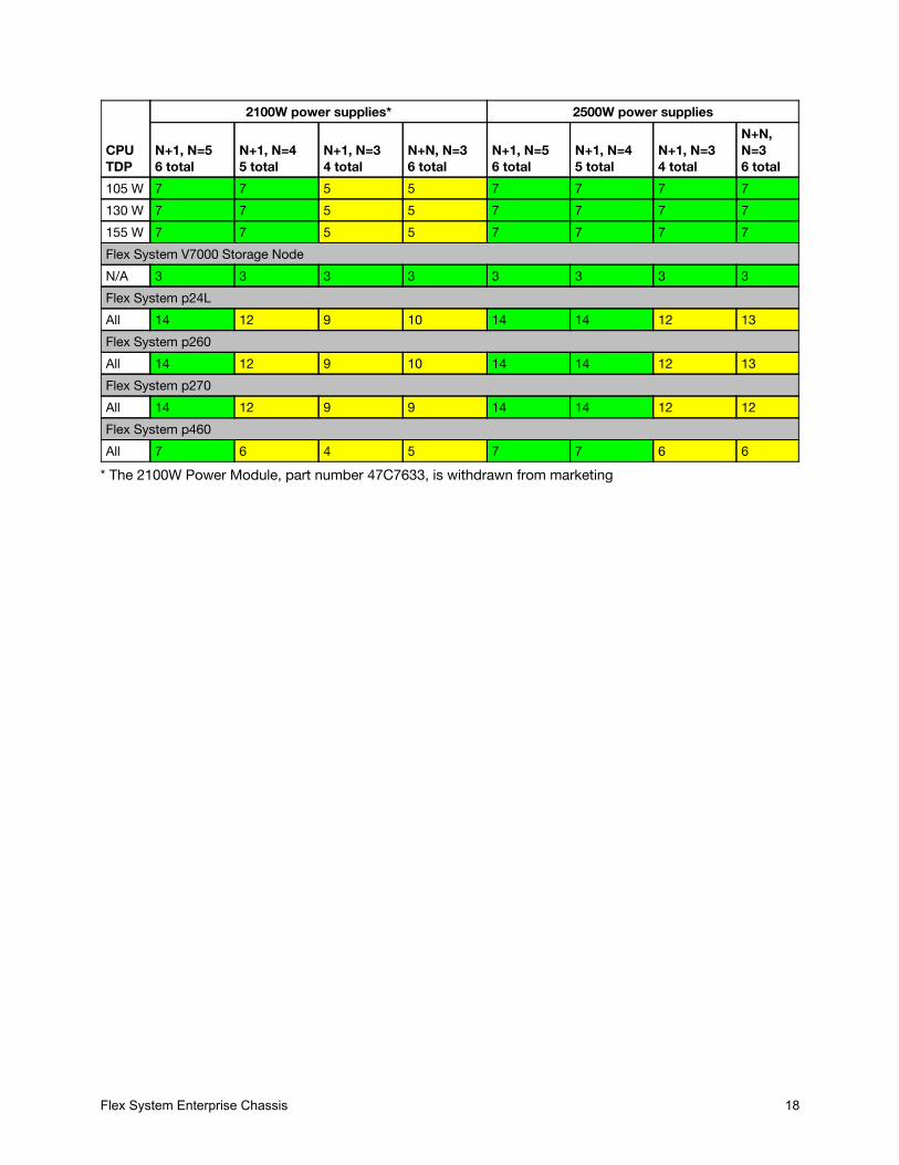
Figure 10. Power supply bay numberingThe following table shows the number of compute nodes that are supported in the chassis based on thepower supplies used (2100W or 2500W), the number of power supplies installed, and the power redundancypolicy enabled (N+1 or N+N).Note: 2100W power supplies are now withdrawn from marketing.In this table, the colors of the cells have the following meaning:
Green cell: Supported with no restrictions as to the number of compute nodes that can be installedYellow cell: Supported but with restrictions on the number of compute nodes that can be installed.
Note: These tables assume the chassis is filled with idential compute nodes. For more complexconfigurations, use the Power Configurator:https://support.lenovo.com/documents/LNVO-PWRCONF
Table 9. Specific number of compute nodes supported based on installed power supplies
CPUTDP
2100W power supplies* 2500W power supplies
N+1, N=56 total
N+1, N=45 total
N+1, N=34 total
N+N, N=36 total
N+1, N=56 total
N+1, N=45 total
N+1, N=34 total
N+N,N=36 total
ThinkSystem SN55070 W 14 14 11 11 14 14 14 1485 W 14 14 11 11 14 14 14 14105 W 14 14 11 11 14 14 14 14125 W 14 14 11 11 14 14 13 14130 W 14 13 11 11 14 14 12 13140 W 14 13 11 11 14 14 12 13150 W 14 12 11 11 14 14 12 12165 W 14 12 11 11 14 14 11 12ThinkSystem SN85085 W 7 7 5 5 7 7 7 7105 W 7 7 5 5 7 7 7 7125 W 7 7 5 5 7 7 6 7
Flex System Enterprise Chassis 16
130 W 7 6 5 5 7 7 6 6140 W 7 6 5 5 7 7 6 6150 W 7 6 5 5 7 7 6 6165 W 7 6 5 5 7 7 5 6Flex System x22050 W 14 14 14 14 14 14 14 1460 W 14 14 14 14 14 14 14 1470 W 14 14 14 14 14 14 14 1480 W 14 14 14 14 14 14 14 1495 W 14 14 14 14 14 14 14 14Flex System x22250 W 14 14 13 14 14 14 14 1460 W 14 14 12 12 14 14 14 1470 W 14 14 11 12 14 14 14 1480 W 14 14 10 11 14 14 13 1495 W 14 13 9 10 14 14 12 13Flex System x24060 W 14 14 11 11 14 14 14 1470 W 14 14 11 11 14 14 14 1480 W 14 14 11 11 14 14 14 1495 W 14 14 11 11 14 14 14 14115 W 14 14 11 11 14 14 14 14130 W 14 14 11 11 14 14 13 14135 W 14 14 11 11 14 14 13 14Flex System x240 M552 W 14 14 11 11 14 14 14 1455 W 14 14 11 11 14 14 14 1465 W 14 14 11 11 14 14 14 1475 W 14 14 11 11 14 14 14 1485 W 14 14 11 11 14 14 14 1490 W 14 14 11 11 14 14 14 14105 W 14 14 11 11 14 14 13 14120 W 14 14 11 11 14 14 13 14135 W 14 13 11 11 14 14 12 13145 W 14 13 11 11 14 14 12 13Flex System x44095 W 7 7 6 6 7 7 7 7115 W 7 7 5 5 7 7 7 7130 W 7 7 5 5 7 7 6 7Flex System x880 X6, x480 X6 and x280 X6
CPUTDP
2100W power supplies* 2500W power supplies
N+1, N=56 total
N+1, N=45 total
N+1, N=34 total
N+N, N=36 total
N+1, N=56 total
N+1, N=45 total
N+1, N=34 total
N+N,N=36 total
Flex System Enterprise Chassis 17
105 W 7 7 5 5 7 7 7 7130 W 7 7 5 5 7 7 7 7155 W 7 7 5 5 7 7 7 7Flex System V7000 Storage NodeN/A 3 3 3 3 3 3 3 3Flex System p24LAll 14 12 9 10 14 14 12 13Flex System p260All 14 12 9 10 14 14 12 13Flex System p270All 14 12 9 9 14 14 12 12Flex System p460All 7 6 4 5 7 7 6 6
CPUTDP
2100W power supplies* 2500W power supplies
N+1, N=56 total
N+1, N=45 total
N+1, N=34 total
N+N, N=36 total
N+1, N=56 total
N+1, N=45 total
N+1, N=34 total
N+N,N=36 total
* The 2100W Power Module, part number 47C7633, is withdrawn from marketing
Flex System Enterprise Chassis 18
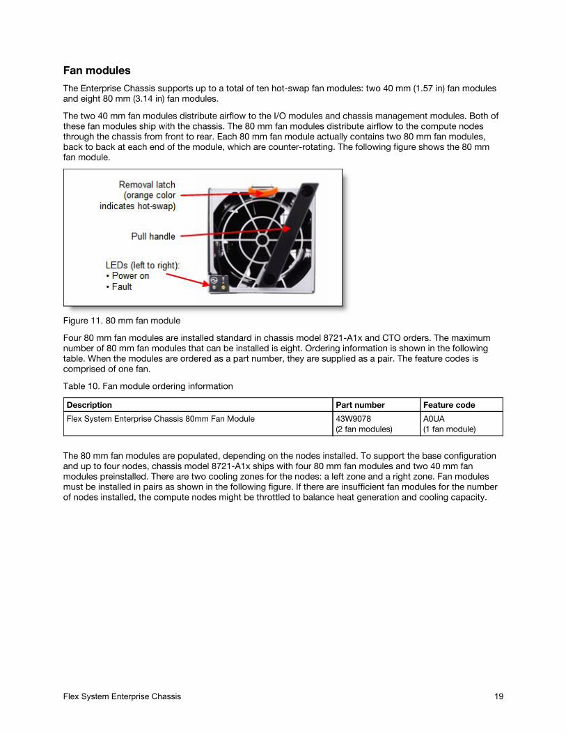
Fan modulesThe Enterprise Chassis supports up to a total of ten hot-swap fan modules: two 40 mm (1.57 in) fan modulesand eight 80 mm (3.14 in) fan modules.The two 40 mm fan modules distribute airflow to the I/O modules and chassis management modules. Both ofthese fan modules ship with the chassis. The 80 mm fan modules distribute airflow to the compute nodesthrough the chassis from front to rear. Each 80 mm fan module actually contains two 80 mm fan modules,back to back at each end of the module, which are counter-rotating. The following figure shows the 80 mmfan module.
Figure 11. 80 mm fan moduleFour 80 mm fan modules are installed standard in chassis model 8721-A1x and CTO orders. The maximumnumber of 80 mm fan modules that can be installed is eight. Ordering information is shown in the followingtable. When the modules are ordered as a part number, they are supplied as a pair. The feature codes iscomprised of one fan.Table 10. Fan module ordering information
Description Part number Feature codeFlex System Enterprise Chassis 80mm Fan Module 43W9078
(2 fan modules)A0UA(1 fan module)
The 80 mm fan modules are populated, depending on the nodes installed. To support the base configurationand up to four nodes, chassis model 8721-A1x ships with four 80 mm fan modules and two 40 mm fanmodules preinstalled. There are two cooling zones for the nodes: a left zone and a right zone. Fan modulesmust be installed in pairs as shown in the following figure. If there are insufficient fan modules for the numberof nodes installed, the compute nodes might be throttled to balance heat generation and cooling capacity.
Flex System Enterprise Chassis 19
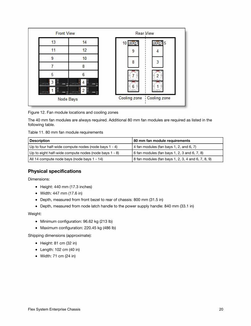
Figure 12. Fan module locations and cooling zonesThe 40 mm fan modules are always required. Additional 80 mm fan modules are required as listed in thefollowing table.Table 11. 80 mm fan module requirements
Description 80 mm fan module requirementsUp to four half-wide compute nodes (node bays 1 - 4) 4 fan modules (fan bays 1, 2, and 6, 7)Up to eight half-wide compute nodes (node bays 1 - 8) 6 fan modules (fan bays 1, 2, 3 and 6, 7, 8)All 14 compute node bays (node bays 1 - 14) 8 fan modules (fan bays 1, 2, 3, 4 and 6, 7, 8, 9)
Physical specificationsDimensions:
Height: 440 mm (17.3 inches)Width: 447 mm (17.6 in)Depth, measured from front bezel to rear of chassis: 800 mm (31.5 in)Depth, measured from node latch handle to the power supply handle: 840 mm (33.1 in)
Weight:Minimum configuration: 96.62 kg (213 lb)Maximum configuration: 220.45 kg (486 lb)
Shipping dimensions (approximate):Height: 81 cm (32 in)Length: 102 cm (40 in)Width: 71 cm (24 in)
Supported environmentFlex System Enterprise Chassis 20
Supported environmentThe Flex System Enterprise Chassis complies with ASHRAE Class A3 specifications.The following environment is the supported operating environment.Temperature:
0 - 914 m (0 - 3,000 ft): 5 - 40 °C (41 - 104 °F)914 m - 3048 m (3,000 - 10,000 ft): The maximum ambient temperature drops 1 °C for every additional178 m (584 ft) increase in altitude until the maximum temperature is 28 °C at 3,048 m (10,000 ft)
Relative humidity: 8% - 85%Maximum altitude: 3,048 m (10,000 ft)Electrical power:
200 - 240 V ac (nominal), 50 or 60 HzMinimum configuration: 0.51 kVA (two power supplies)Maximum configuration: 13 kVA (six power supplies)
Power consumption: 12,900 watts maximumThermal output, full configuration - 12,900 watts (43,900 Btu/hr)Acoustical noise emissions for Flex Chassis:
7.5 bels operating7.5 bels idling
The noise emission level stated is the declared (upper limit) sound power level, in bels, for a random sampleof machines. All measurements are made in accordance with ISO 7779 and reported in conformance with ISO9296.
Warranty optionsThe system has a three-year warranty with 24x7 standard call center support and 9x5 Next Business Dayonsite coverage. Also available are Lenovo Services warranty maintenance upgrades and post-warrantymaintenance agreements, with a well-defined scope of services, including service hours, response time, termof service, and service agreement terms and conditions.Lenovo warranty service upgrade offerings are country-specific. Not all warranty service upgrades areavailable in every country. For more information about Lenovo warranty service upgrade offerings that areavailable in your country, go to the Data Center Advisor and Configurator (formerly known as LESC) websitehttp://lesc.lenovo.com, then do the following:
1. In the Customize a Model box in the middle of the page, select the Services option in theCustomization Option dropdown menu
2. Enter in the machine type & model of the system3. From the search results, you can click either Deployment Services or Support Services to view the
offeringsThe following table explains warranty service definitions in more detail.
Flex System Enterprise Chassis 21
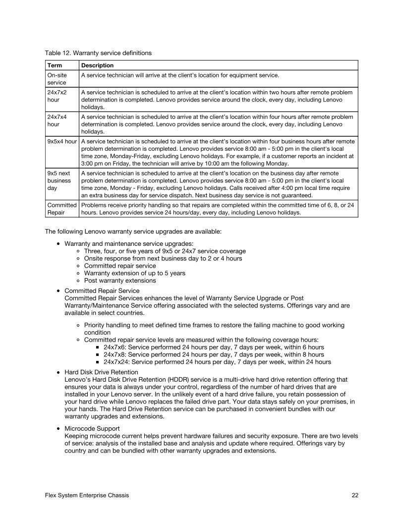
Table 12. Warranty service definitionsTerm DescriptionOn-siteservice
A service technician will arrive at the client’s location for equipment service.
24x7x2hour
A service technician is scheduled to arrive at the client’s location within two hours after remote problemdetermination is completed. Lenovo provides service around the clock, every day, including Lenovoholidays.
24x7x4hour
A service technician is scheduled to arrive at the client’s location within four hours after remote problemdetermination is completed. Lenovo provides service around the clock, every day, including Lenovoholidays.
9x5x4 hour A service technician is scheduled to arrive at the client’s location within four business hours after remoteproblem determination is completed. Lenovo provides service 8:00 am - 5:00 pm in the client's localtime zone, Monday-Friday, excluding Lenovo holidays. For example, if a customer reports an incident at3:00 pm on Friday, the technician will arrive by 10:00 am the following Monday.
9x5 nextbusinessday
A service technician is scheduled to arrive at the client’s location on the business day after remoteproblem determination is completed. Lenovo provides service 8:00 am - 5:00 pm in the client's localtime zone, Monday - Friday, excluding Lenovo holidays. Calls received after 4:00 pm local time requirean extra business day for service dispatch. Next business day service is not guaranteed.
CommittedRepair
Problems receive priority handling so that repairs are completed within the committed time of 6, 8, or 24hours. Lenovo provides service 24 hours/day, every day, including Lenovo holidays.
The following Lenovo warranty service upgrades are available:Warranty and maintenance service upgrades:
Three, four, or five years of 9x5 or 24x7 service coverageOnsite response from next business day to 2 or 4 hoursCommitted repair serviceWarranty extension of up to 5 yearsPost warranty extensions
Committed Repair ServiceCommitted Repair Services enhances the level of Warranty Service Upgrade or PostWarranty/Maintenance Service offering associated with the selected systems. Offerings vary and areavailable in select countries.
Priority handling to meet defined time frames to restore the failing machine to good workingconditionCommitted repair service levels are measured within the following coverage hours:
24x7x6: Service performed 24 hours per day, 7 days per week, within 6 hours24x7x8: Service performed 24 hours per day, 7 days per week, within 8 hours24x7x24: Service performed 24 hours per day, 7 days per week, within 24 hours
Hard Disk Drive RetentionLenovo’s Hard Disk Drive Retention (HDDR) service is a multi-drive hard drive retention offering thatensures your data is always under your control, regardless of the number of hard drives that areinstalled in your Lenovo server. In the unlikely event of a hard drive failure, you retain possession ofyour hard drive while Lenovo replaces the failed drive part. Your data stays safely on your premises, inyour hands. The Hard Drive Retention service can be purchased in convenient bundles with ourwarranty upgrades and extensions.Microcode SupportKeeping microcode current helps prevent hardware failures and security exposure. There are two levelsof service: analysis of the installed base and analysis and update where required. Offerings vary bycountry and can be bundled with other warranty upgrades and extensions.
Flex System Enterprise Chassis 22
Remote Technical Support Services (RTS)RTS provides comprehensive technical call center support for covered servers, storage, operatingsystems, and applications. Providing a single source for support of hardware and software issues, RTScan reduce problem resolution time, decreasing the cost to address technical problems and increasinguptime. Offerings are available for Windows, Linux, IBM Systems Director, VMware, Microsoft businessapplications, and Lenovo System x storage devices, and IBM OEM storage devices.
Regulatory complianceThe server conforms to the following standards:
ASHRAE Class A3FCC - Verified to comply with Part 15 of the FCC Rules Class ACanada ICES-004, issue 3 Class AUL/IEC 60950-1CSA C22.2 No. 60950-1NOM-019Argentina IEC 60950-1Japan VCCI, Class AIEC 60950-1 (CB Certificate and CB Test Report)China CCC (GB4943); (GB9254, Class A); (GB17625.1)Taiwan BSMI CNS13438, Class A; CNS14336Australia/New Zealand AS/NZS CISPR 22, Class AKorea KN22, Class A, KN24Russia/GOST ME01, IEC 60950-1, GOST R 51318.22, GOST R 51318.249, GOST R 51317.3.2, GOSTR 51317.3.3CE Mark (EN55022 Class A, EN60950-1, EN55024, EN61000-3-2, EN61000-3-3)CISPR 22, Class ATUV-GS (EN60950-1/IEC 60950-1, EK1-ITB2000)
Top-of-rack Ethernet switchesFlex System Enterprise Chassis 23

Top-of-rack Ethernet switchesFor enterprise-class installations with multiple Flex System Enterprise Chassis configurations, a top-of-rackEthernet switch from Lenovo provides the necessary level of networking between racks of systems and therest of your production network.The following table lists the Ethernet LAN switches that are offered by Lenovo.
Table 13. Ethernet LAN switchesPart number Description1 Gb Ethernet switches7165H1X Juniper EX2300-C PoE Switch7165H2X Juniper EX2300-24p PoE Switch7Y810011WW Lenovo ThinkSystem NE0152T RackSwitch (Rear to Front)7Z320O11WW Lenovo ThinkSystem NE0152TO RackSwitch (Rear to Front, ONIE)7159BAX Lenovo RackSwitch G7028 (Rear to Front)7159CAX Lenovo RackSwitch G7052 (Rear to Front)7159G52 Lenovo RackSwitch G8052 (Rear to Front)10 Gb Ethernet switches7159A1X Lenovo ThinkSystem NE1032 RackSwitch (Rear to Front)7159B1X Lenovo ThinkSystem NE1032T RackSwitch (Rear to Front)7159C1X Lenovo ThinkSystem NE1072T RackSwitch (Rear to Front)7159BR6 Lenovo RackSwitch G8124E (Rear to Front)7159CRW Lenovo RackSwitch G8272 (Rear to Front)7159GR6 Lenovo RackSwitch G8296 (Rear to Front)25 Gb Ethernet switches7159E1X Lenovo ThinkSystem NE2572 RackSwitch (Rear to Front)7Z210O21WW Lenovo ThinkSystem NE2572O RackSwitch (Rear to Front, ONIE)100 Gb Ethernet switches7159D1X Lenovo ThinkSystem NE10032 RackSwitch (Rear to Front)7Z210O11WW Lenovo ThinkSystem NE10032O RackSwitch (Rear to Front, ONIE)
For more information, see the list of Product Guides in the following switch categories:1 Gb Ethernet switches: http://lenovopress.com/networking/tor/1gb?rt=product-guide10 Gb Ethernet switches: http://lenovopress.com/networking/tor/10gb?rt=product-guide25 Gb Ethernet switches: http://lenovopress.com/networking/tor/25gb?rt=product-guide40 Gb Ethernet switches: http://lenovopress.com/networking/tor/40gb?rt=product-guide100 Gb Ethernet switches: https://lenovopress.com/networking/tor/100Gb?rt=product-guide
Fibre Channel SAN switchesFlex System Enterprise Chassis 24
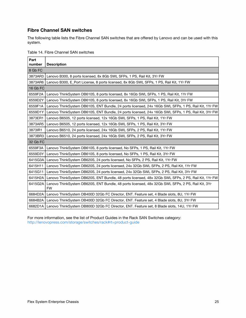
Fibre Channel SAN switchesThe following table lists the Fibre Channel SAN switches that are offered by Lenovo and can be used with thissystem.
Table 14. Fibre Channel SAN switchesPartnumber Description8 Gb FC3873AR3 Lenovo B300, 8 ports licensed, 8x 8Gb SWL SFPs, 1 PS, Rail Kit, 3Yr FW3873AR6 Lenovo B300, E_Port License, 8 ports licensed, 8x 8Gb SWL SFPs, 1 PS, Rail Kit, 1Yr FW16 Gb FC6559F2A Lenovo ThinkSystem DB610S, 8 ports licensed, 8x 16Gb SWL SFPs, 1 PS, Rail Kit, 1Yr FW6559D2Y Lenovo ThinkSystem DB610S, 8 ports licensed, 8x 16Gb SWL SFPs, 1 PS, Rail Kit, 3Yr FW6559F1A Lenovo ThinkSystem DB610S, ENT Bundle, 24 ports licensed, 24x 16Gb SWL SFPs, 1 PS, Rail Kit, 1Yr FW6559D1Y Lenovo ThinkSystem DB610S, ENT Bundle, 24 ports licensed, 24x 16Gb SWL SFPs, 1 PS, Rail Kit, 3Yr FW3873ER1 Lenovo B6505, 12 ports licensed, 12x 16Gb SWL SFPs, 1 PS, Rail Kit, 1Yr FW3873AR5 Lenovo B6505, 12 ports licensed, 12x 16Gb SWL SFPs, 1 PS, Rail Kit, 3Yr FW3873IR1 Lenovo B6510, 24 ports licensed, 24x 16Gb SWL SFPs, 2 PS, Rail Kit, 1Yr FW3873BR3 Lenovo B6510, 24 ports licensed, 24x 16Gb SWL SFPs, 2 PS, Rail Kit, 3Yr FW32 Gb FC6559F3A Lenovo ThinkSystem DB610S, 8 ports licensed, No SFPs, 1 PS, Rail Kit, 1Yr FW6559D3Y Lenovo ThinkSystem DB610S, 8 ports licensed, No SFPs, 1 PS, Rail Kit, 3Yr FW6415G3A Lenovo ThinkSystem DB620S, 24 ports licensed, No SFPs, 2 PS, Rail Kit, 1Yr FW6415H11 Lenovo ThinkSystem DB620S, 24 ports licensed, 24x 32Gb SWL SFPs, 2 PS, Rail Kit, 1Yr FW6415G11 Lenovo ThinkSystem DB620S, 24 ports licensed, 24x 32Gb SWL SFPs, 2 PS, Rail Kit, 3Yr FW6415H2A Lenovo ThinkSystem DB620S, ENT Bundle, 48 ports licensed, 48x 32Gb SWL SFPs, 2 PS, Rail Kit, 1Yr FW6415G2A Lenovo ThinkSystem DB620S, ENT Bundle, 48 ports licensed, 48x 32Gb SWL SFPs, 2 PS, Rail Kit, 3Yr
FW6684D2A Lenovo ThinkSystem DB400D 32Gb FC Director, ENT. Feature set, 4 Blade slots, 8U, 1Yr FW6684B2A Lenovo ThinkSystem DB400D 32Gb FC Director, ENT. Feature set, 4 Blade slots, 8U, 3Yr FW6682D1A Lenovo ThinkSystem DB800D 32Gb FC Director, ENT. Feature set, 8 Blade slots, 14U, 1Yr FW
For more information, see the list of Product Guides in the Rack SAN Switches category:http://lenovopress.com/storage/switches/rack#rt=product-guide
Power distribution unitsFlex System Enterprise Chassis 25
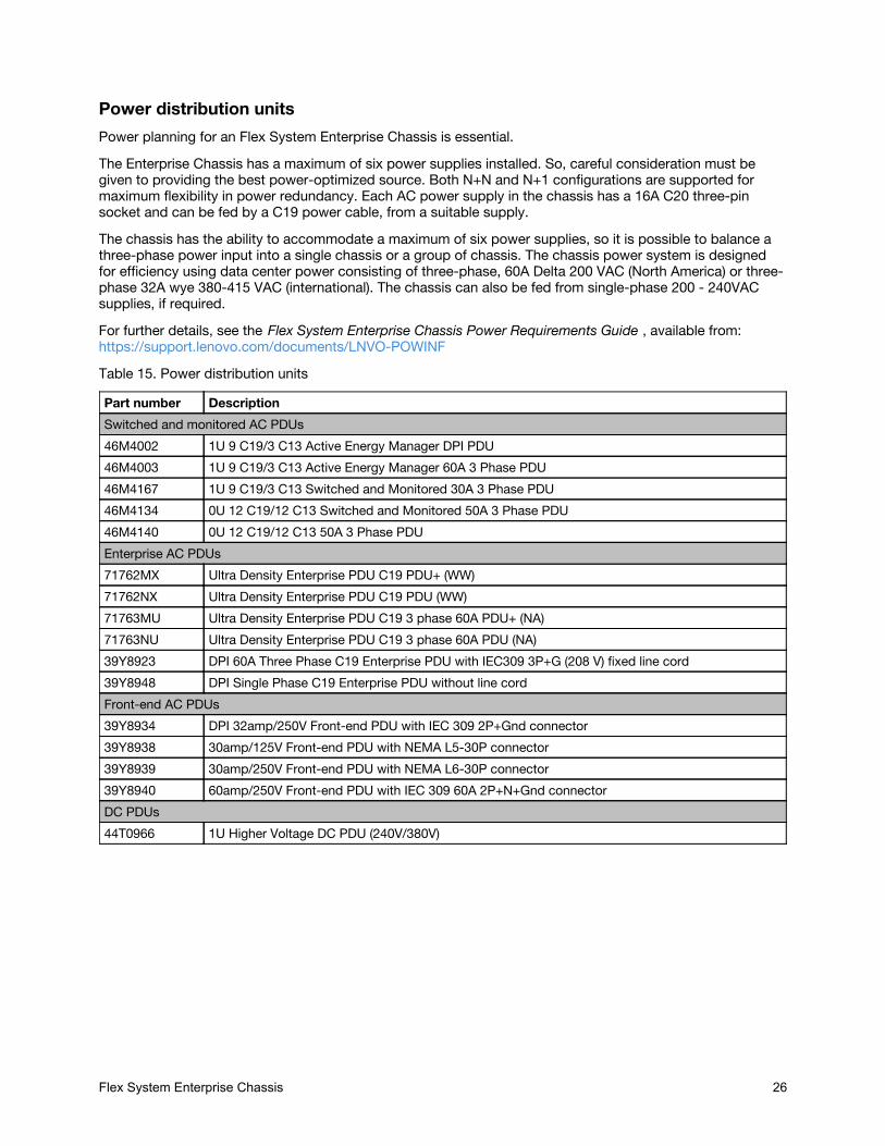
Power distribution unitsPower planning for an Flex System Enterprise Chassis is essential.The Enterprise Chassis has a maximum of six power supplies installed. So, careful consideration must begiven to providing the best power-optimized source. Both N+N and N+1 configurations are supported formaximum flexibility in power redundancy. Each AC power supply in the chassis has a 16A C20 three-pinsocket and can be fed by a C19 power cable, from a suitable supply.The chassis has the ability to accommodate a maximum of six power supplies, so it is possible to balance athree-phase power input into a single chassis or a group of chassis. The chassis power system is designedfor efficiency using data center power consisting of three-phase, 60A Delta 200 VAC (North America) or three-phase 32A wye 380-415 VAC (international). The chassis can also be fed from single-phase 200 - 240VACsupplies, if required.For further details, see the Flex System Enterprise Chassis Power Requirements Guide , available from:https://support.lenovo.com/documents/LNVO-POWINFTable 15. Power distribution units
Part number DescriptionSwitched and monitored AC PDUs46M4002 1U 9 C19/3 C13 Active Energy Manager DPI PDU46M4003 1U 9 C19/3 C13 Active Energy Manager 60A 3 Phase PDU46M4167 1U 9 C19/3 C13 Switched and Monitored 30A 3 Phase PDU46M4134 0U 12 C19/12 C13 Switched and Monitored 50A 3 Phase PDU46M4140 0U 12 C19/12 C13 50A 3 Phase PDUEnterprise AC PDUs71762MX Ultra Density Enterprise PDU C19 PDU+ (WW)71762NX Ultra Density Enterprise PDU C19 PDU (WW)71763MU Ultra Density Enterprise PDU C19 3 phase 60A PDU+ (NA)71763NU Ultra Density Enterprise PDU C19 3 phase 60A PDU (NA)39Y8923 DPI 60A Three Phase C19 Enterprise PDU with IEC309 3P+G (208 V) fixed line cord39Y8948 DPI Single Phase C19 Enterprise PDU without line cordFront-end AC PDUs39Y8934 DPI 32amp/250V Front-end PDU with IEC 309 2P+Gnd connector39Y8938 30amp/125V Front-end PDU with NEMA L5-30P connector39Y8939 30amp/250V Front-end PDU with NEMA L6-30P connector39Y8940 60amp/250V Front-end PDU with IEC 309 60A 2P+N+Gnd connectorDC PDUs44T0966 1U Higher Voltage DC PDU (240V/380V)
Uninterruptible power supply unitsFlex System Enterprise Chassis 26

Uninterruptible power supply unitsThe Flex System Enterprise Chassis supports attachments to the uninterruptible power supply units listed inthe following table.Table 16. Uninterruptible power supply units
Part number Description55946KX RT6kVA 3U Rack or Tower UPS (200-240VAC)55948KX RT8kVA 6U Rack or Tower UPS (200-240VAC)55949KX RT11kVA 6U Rack or Tower UPS (200-240VAC)55948PX RT8kVA 6U 3:1 Phase Rack or Tower UPS (380-415VAC)55949PX RT11kVA 6U 3:1 Phase Rack or Tower UPS (380-415VAC)
For more information, see the related Lenovo Press Product Guides in the UPS category:https://lenovopress.com/servers/options/ups
Rack cabinetsFlex System Enterprise Chassis 27
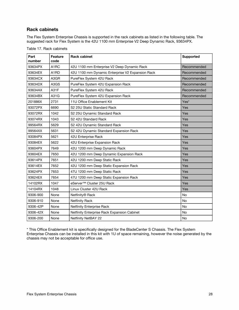
Rack cabinetsThe Flex System Enterprise Chassis is supported in the rack cabinets as listed in the following table. Thesuggested rack for Flex System is the 42U 1100 mm Enterprise V2 Deep Dynamic Rack, 93634PX.Table 17. Rack cabinets
Partnumber
Featurecode
Rack cabinet Supported
93634PX A1RC 42U 1100 mm Enterprise V2 Deep Dynamic Rack Recommended93634EX A1RD 42U 1100 mm Dynamic Enterprise V2 Expansion Rack Recommended93634CX A3GR PureFlex System 42U Rack Recommended93634DX A3GS PureFlex System 42U Expansion Rack Recommended93634AX A31F PureFlex System 42U Rack Recommended93634BX A31G PureFlex System 42U Expansion Rack Recommended201886X 2731 11U Office Enablement Kit Yes*93072PX 6690 S2 25U Static Standard Rack Yes93072RX 1042 S2 25U Dynamic Standard Rack Yes93074RX 1043 S2 42U Standard Rack Yes99564RX 5629 S2 42U Dynamic Standard Rack Yes99564XX 5631 S2 42U Dynamic Standard Expansion Rack Yes93084PX 5621 42U Enterprise Rack Yes93084EX 5622 42U Enterprise Expansion Rack Yes93604PX 7649 42U 1200 mm Deep Dynamic Rack Yes93604EX 7650 42U 1200 mm Deep Dynamic Expansion Rack Yes93614PX 7651 42U 1200 mm Deep Static Rack Yes93614EX 7652 42U 1200 mm Deep Static Expansion Rack Yes93624PX 7653 47U 1200 mm Deep Static Rack Yes93624EX 7654 47U 1200 mm Deep Static Expansion Rack Yes14102RX 1047 eServer™ Cluster 25U Rack Yes14104RX 1048 Linux Cluster 42U Rack Yes9306-900 None Netfinity® Rack No9306-910 None Netfinity Rack No9306-42P None Netfinity Enterprise Rack No9306-42X None Netfinity Enterprise Rack Expansion Cabinet No9306-200 None Netfinity NetBAY 22 No
* This Office Enablement kit is specifically designed for the BladeCenter S Chassis. The Flex SystemEnterprise Chassis can be installed in this kit with 1U of space remaining, however the noise generated by thechassis may not be acceptable for office use.
Lenovo Financial ServicesFlex System Enterprise Chassis 28

Lenovo Financial ServicesLenovo Financial Services reinforces Lenovo’s commitment to deliver pioneering products and services thatare recognized for their quality, excellence, and trustworthiness. Lenovo Financial Services offers financingsolutions and services that complement your technology solution anywhere in the world.We are dedicated to delivering a positive finance experience for customers like you who want to maximizeyour purchase power by obtaining the technology you need today, protect against technology obsolescence,and preserve your capital for other uses.We work with businesses, non-profit organizations, governments and educational institutions to finance theirentire technology solution. We focus on making it easy to do business with us. Our highly experienced teamof finance professionals operates in a work culture that emphasizes the importance of providing outstandingcustomer service. Our systems, processes and flexible policies support our goal of providing customers witha positive experience.We finance your entire solution. Unlike others, we allow you to bundle everything you need from hardware andsoftware to service contracts, installation costs, training fees, and sales tax. If you decide weeks or monthslater to add to your solution, we can consolidate everything into a single invoice.Our Premier Client services provide large accounts with special handling services to ensure these complextransactions are serviced properly. As a premier client, you have a dedicated finance specialist who managesyour account through its life, from first invoice through asset return or purchase. This specialist develops anin-depth understanding of your invoice and payment requirements. For you, this dedication provides a high-quality, easy, and positive financing experience.For your region specific offers please ask your Lenovo sales representative or your technology provider aboutthe use of Lenovo Financial Services. For more information, see the following Lenovo website:http://www.lenovofs.com
Related publications and linksFor more information, see the following resources:
Flex System product pagehttps://www3.lenovo.com/us/en/data-center/servers/flex-blade-servers/c/blades-flex/US Product Announcement for the Flex System Enterprise Chassishttp://ibm.com/common/ssi/cgi-bin/ssialias?infotype=dd&subtype=ca&&htmlfid=897/ENUS112-053Flex System Information Centerhttp://flexsystem.lenovofiles.com/help/index.jspFlex System Enterprise Chassis Installation and Service Guidehttp://flexsystem.lenovofiles.com/help/topic/com.lenovo.acc.8721.doc/printable_doc.html?cp=0_4_0_0ServerProven hardware compatibility page for Flex Systemhttp://www.lenovo.com/us/en/serverprovenFlex System Interoperability Guidehttp://lenovopress.com/fsigPower Configuratorhttps://support.lenovo.com/documents/LNVO-PWRCONFFlex System Enterprise Chassis Power Requirements Guide https://support.lenovo.com/documents/LNVO-POWINFLenovo Flex System Products and Technology , SG24-8255http://lenovopress.com/sg248255IBM System Storage® Interoperation Centerhttp://www.ibm.com/systems/support/storage/ssic
Related product familiesFlex System Enterprise Chassis 29
Related product familiesProduct families related to this document are the following:
Blade Chassis
Flex System Enterprise Chassis 30
NoticesLenovo may not offer the products, services, or features discussed in this document in all countries. Consult your localLenovo representative for information on the products and services currently available in your area. Any reference to aLenovo product, program, or service is not intended to state or imply that only that Lenovo product, program, orservice may be used. Any functionally equivalent product, program, or service that does not infringe any Lenovointellectual property right may be used instead. However, it is the user's responsibility to evaluate and verify theoperation of any other product, program, or service. Lenovo may have patents or pending patent applications coveringsubject matter described in this document. The furnishing of this document does not give you any license to thesepatents. You can send license inquiries, in writing, to:
Lenovo (United States), Inc.1009 Think Place - Building OneMorrisville, NC 27560U.S.A.Attention: Lenovo Director of Licensing
LENOVO PROVIDES THIS PUBLICATION ”AS IS” WITHOUT WARRANTY OF ANY KIND, EITHER EXPRESS ORIMPLIED, INCLUDING, BUT NOT LIMITED TO, THE IMPLIED WARRANTIES OF NON-INFRINGEMENT,MERCHANTABILITY OR FITNESS FOR A PARTICULAR PURPOSE. Some jurisdictions do not allow disclaimer ofexpress or implied warranties in certain transactions, therefore, this statement may not apply to you.
This information could include technical inaccuracies or typographical errors. Changes are periodically made to theinformation herein; these changes will be incorporated in new editions of the publication. Lenovo may makeimprovements and/or changes in the product(s) and/or the program(s) described in this publication at any time withoutnotice.
The products described in this document are not intended for use in implantation or other life support applicationswhere malfunction may result in injury or death to persons. The information contained in this document does not affector change Lenovo product specifications or warranties. Nothing in this document shall operate as an express orimplied license or indemnity under the intellectual property rights of Lenovo or third parties. All information contained inthis document was obtained in specific environments and is presented as an illustration. The result obtained in otheroperating environments may vary. Lenovo may use or distribute any of the information you supply in any way it believesappropriate without incurring any obligation to you.
Any references in this publication to non-Lenovo Web sites are provided for convenience only and do not in anymanner serve as an endorsement of those Web sites. The materials at those Web sites are not part of the materials forthis Lenovo product, and use of those Web sites is at your own risk. Any performance data contained herein wasdetermined in a controlled environment. Therefore, the result obtained in other operating environments may varysignificantly. Some measurements may have been made on development-level systems and there is no guarantee thatthese measurements will be the same on generally available systems. Furthermore, some measurements may havebeen estimated through extrapolation. Actual results may vary. Users of this document should verify the applicabledata for their specific environment.
© Copyright Lenovo 2018. All rights reserved.
This document, TIPS0863, was created or updated on August 21, 2018.Send us your comments in one of the following ways:
Use the online Contact us review form found at:http://lenovopress.com/TIPS0863Send your comments in an e-mail to:[email protected]
This document is available online at http://lenovopress.com/TIPS0863.
Flex System Enterprise Chassis 31
TrademarksLenovo and the Lenovo logo are trademarks or registered trademarks of Lenovo in the United States, othercountries, or both. A current list of Lenovo trademarks is available on the Web athttps://www.lenovo.com/us/en/legal/copytrade/.The following terms are trademarks of Lenovo in the United States, other countries, or both:BladeCenter®Flex SystemLenovo ServicesLenovo XClarityLenovo®Netfinity®RackSwitchServerProven®System x®ThinkSystemTopSellerThe following terms are trademarks of other companies:Linux® is a trademark of Linus Torvalds in the United States, other countries, or both.Microsoft® and Windows® are trademarks of Microsoft Corporation in the United States, other countries, orboth.Other company, product, or service names may be trademarks or service marks of others.
Flex System Enterprise Chassis 32