flexen125 ≥ª¡ˆ 100303 - channel-es litrature/ls c… · · 2012-10-244. filler 5. binder...
TRANSCRIPT


Cable ProductsOffshore & Marine CableLS Offshore and Marine Cables comply with the majority of international standards and hold various certifications. Our products have been chosen by various international offshoreand marine projects, and they have shown satisfaction with performance of our products.
We also put great emphasis on R&D to keep our technology on the cutting edge to satisfyever-changing demands of this industry, and as a leading manufacturer, we provide advanced solutions to our customers.
Cable Products have been proved to meet the delicate requirements of IEEE 1580 Type P standards, and it is designed to provide reliance and easiness during theoperations in harmful environments of offshore and marine industry. Special features likesuperior flexibility, flame retardant, cold resistant, drilling mud resistant, crush & impact resist-ant, low smoke, halogen-free, and other resistant(oil, abrasion, petrochemical fluids, moisture,and sunlight) show our advanced technology, which will thoroughly satisfy our customer's specific needs.

ContentsPower Distribution Cable
Power Distribution Cable - 2kV Power Distribution Cable - 0.6/1kV
0.6/1kV Control Cable0.6/1kV Control Cable - Non Shield
0.6/1kV Control Cable - Overall Shield0.6/1kV Control Cable - Overall Braid Shield
0.6/1kV Signal Cable0.6/1kV Signal Cable - Overall Shield
0.6/1kV Signal Cable - Overall Braid Shield0.6/1kV Signal Cable - Individual Shield
0.6/1kV Signal Cable - Individual & Overall Shield
High Voltage Power CableHigh Voltage Power Cable - 5kV, 8kV, 15kV
Technical Data & Installation InformationTechnical Data
Installation InformationNetwork

Cable Designation
Example
AL/PS Tape : Aluminum backed polyester tape
According to IEEE 1580(2001), IEEE 45(2002)
Cable Type
S Single - Conductor Distribution C Control
D Two - Conductor Distribution TP Twisted Pair
T Three -Conductor Distribution TT Twisted Triad
F Four - Conductor Distribution FS Fire Resistant
Q Five - Conductor Distribution
GroupShielding
(None) Unshielded (OBS) Overall Tinned Copper Braid Shielded
(OS) Overall Shield (IS-OBS) Individually Shielded and Overall Tinned
(IS) Individually Shielded Copper Braid Shielded
(IS-OS) Individually Shielded and Overall Shielded
InsulationType
E Ethylene Propylene Rubber S Silicone Rubber
X Cross-Linked Polyethylene P Cross-linked Polyolefin
T Polyvinyl Chloride LSX Low - smoke Cross-linked Polyolefin
T/N Polyvinyl Chloride / Nylon LSE Low - smoke Ethylene Propylene Rubber
Jacket and / orSheath Type
T Thermoplastic Polyvinyl Chloride L Cross-linked Polyolefin (Low-smoke)
CP Thermosetting Chlorosulfonated Polyethylene
N Thermosetting Polychloroprene(neoprene) TPO Thermoplastic Polyolefin (Low-smoke)
M Mud resistant Cross-linked Polyolefin
Armor
(None) Unarmored T Tin-coated Copper
A Aluminum S Armor with Sheath
B Bronze
0.6/1kV TP (I/S - OS) PNBSVoltage
Twisted Pair
Insulation(Type P)
Individually Shielded(AL/PS Tape)
Overall Shielded(AL/PS Tape)
Jacket(Neoprene)
Armor(Bronze)
Sheath(Neoprene)
Voltage
Seperator Tape
No. of Conductor(Three)
Insulation(Type P)
Jacket(Neoprene)
Armor(Bronze)
Sheath(Neoprene)
0.6/1kV TPNBS

Power Distribution CablePower Distribution Cable - 0.6/1kV
Power Distribution Cable - 2kv
Power Distribution Cable- 2kV
9
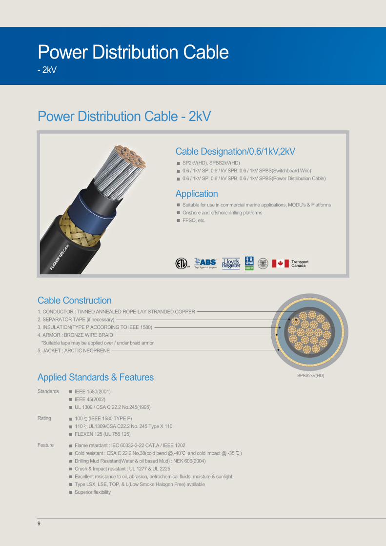
Power Distribution Cable - 2kV
Cable Construction1. CONDUCTOR : TINNED ANNEALED ROPE-LAY STRANDED COPPER
2. SEPARATOR TAPE (if necessary)
3. INSULATION(TYPE P ACCORDING TO IEEE 1580)
4. ARMOR : BRONZE WIRE BRAID
*Suitable tape may be applied over / under braid armor
5. JACKET : ARCTIC NEOPRENE
SPBS2kV(HD)
Cable Designation/0.6/1kV,2kVSP2kV(HD), SPBS2kV(HD)
0.6 / 1kV SP, 0.6 / kV SPB, 0.6 / 1kV SPBS(Switchboard Wire)
0.6 / 1kV SP, 0.6 / kV SPB, 0.6 / 1kV SPBS(Power Distribution Cable)
Application Suitable for use in commercial marine applications, MODU's & Platforms
Onshore and offshore drilling platforms
FPSO, etc.
Applied Standards & FeaturesIEEE 1580(2001)
IEEE 45(2002)
UL 1309 / CSA C 22.2 No.245(1995)
100 (IEEE 1580 TYPE P)
110 UL1309/CSA C22.2 No. 245 Type X 110
FLEXEN 125 (UL 758 125)
Standards
Rating
Flame retardant : IEC 60332-3-22 CAT.A / IEEE 1202
Cold resistant : CSA C 22.2 No.38(cold bend @ -40 and cold impact @ -35 )
Drilling Mud Resistant(Water & oil based Mud) : NEK 606(2004)
Crush & Impact resistant : UL 1277 & UL 2225
Excellent resistance to oil, abrasion, petrochemical fluids, moisture & sunlight.
Type LSX, LSE, TOP, & L(Low Smoke Halogen Free) available
Superior flexibility
Feature

Offshore & Marine Cable 10
No.
of coresConductor
size
SP2kV(HD), SPBS2kV(HD)
AWG/MCM
CompositionConductordiameter
Nos/AWG mm inch
Insulationthickness
mm inch
Sheaththickness
mm
Impedance(Phase-Neutral)
/km /1000ftinch
Overalldiameter
mm inch
ApproxWeight
lbs/1000ft
Conductor Unarmored
Overalldiameter
mm mmkg/km kg/kminch
ApproxWeight
lbs/1000ft
Armor
inch lbs/1000ft
Armor & Sheath
Inductance
/km /1000ft
Reactance(at 50Hz)
/km /1000ft
Capacitance
/km /1000ft
1
Overalldiameter
ApproxWeight
kg/km
No.
of coresConductor
size
0.6/1kV SP (Switchboard Wire)
AWG/MCM
CompositionConductordiameter
Nos/AWG mm inch
Insulationthickness
mm inch
Sheaththickness
mm
Impedance(Phase-Neutral)
/km /1000ftinch
Overalldiameter
mm inch
ApproxWeight
lbs/1000ft
Conductor Unarmored
Inductance
/km /1000ft
Reactance(at 50Hz)
/km /1000ft
Capacitance
/km /1000ftkg/km
1
No.
of coresConductor
size
0.6/1kV SPN(Switchboard Wire)
AWG/MCM
CompositionConductordiameter
Insulation thickness
Nos/AWG mm inch
Conductor
mm inch
Sheath thickness
mm inch
Overalldiameter
mm kg/km
ApproxWeight
lbs/1000ft
Inductance
inch /km /1000ft
Reactance(at 50Hz)
/km /1000ft
Capacitance
/km /1000ft
1

11
Power Distribution Cable - 0.6/1kV
Cable Construction1. CONDUCTOR : TINNED ANNEALED ROPE-LAY STRANDED COPPER
2. SEPARATOR TAPE(if necessary)
3. INSULATION(TYPE P ACCORDING TO IEEE 1580)
4. FILLER
5. BINDER TAPE
6. JACKET : ARCTIC NEOPRENE
7. ARMOR : BRONZE WIRE BRAID
*Suitable tape may be applied over / under braid armor
8. JACKET : ARCTIC NEOPRENE DPNBS, TPNBS, FPNBS
Cable Designation / 0.6/1kV0.6/1kV SPN(Switchboard Wire)
0.6/1kV SPN(Power Distribution Cable)
0.6/1kV DPN, 0.6/1kV DPNBS
0.6/1kV TPN, 0.6/1kV TPNBS
0.6/1kV FPN, 0.6/1kV FPNBS
0.6/1kV QPN, 0.6/1kV QPNBS
Application Suitable for use in commercial marine applications, MODU's & Platforms
Onshore and offshore drilling platforms
FPSO, etc.
Power Distribution Cable- 0.6/1kV
Applied Standards & FeaturesIEEE 1580(2001)
IEEE 45(2002)
UL 1309 / CSA C 22.2 No.245(1995)
100 (IEEE 1580 TYPE P)
110 UL1309/CSA C22.2 No. 245 Type X 110
FLEXEN 125 (UL 758 125)
Standards
Rating
Flame retardant : IEC 60332-3-22 CAT.A / IEEE 1202
Cold resistant : CSA C 22.2 No.38(cold bend @ -40 and cold impact @ -35 )
Drilling Mud Resistant(Water & oil based Mud) : NEK 606(2004)
Crush & Impact resistant : UL 1277 & UL 2225
Excellent resistance to oil, abrasion, petrochemical fluids, moisture & sunlight.
Type LSX, LSE, TOP, & L(Low Smoke Halogen Free) available
Superior flexibility
Feature

Offshore & Marine Cable 12
12
No.
of coresConductor
size
0.6/1kV SPN(Switchboard Wire)
AWG/MCM
CompositionConductordiameter
Insulation thickness
Nos/AWG mm inch
Conductor
mm inch
Sheath thickness
mm inch
Overalldiameter
mm kg/km
ApproxWeight
lbs/1000ft
Inductance
inch /km /1000ft
Reactance(at 50Hz)
/km /1000ft
Capacitance
/km /1000ft
No.
of coresConductor
size
0.6/1kV DPN, 0.6/1kV DPNBS
AWG/MCM
CompositionConductordiameter
Nos/AWG mm inch
Insulationthickness
mm inch
Jacketthickness
Sheaththickness
mm
Impedance(Phase-Neutral)
/km /1000ftinch mm inch
Conductor
Overalldiameter
mm kg/kminch
ApproxWeight
lbs/1000ft
Unarmored
Overalldiameter
mm inch
ApproxWeight
lbs/1000ft
Armor & Sheath
Inductance
/km /1000ft
Reactance(at 50Hz)
/km /1000ft
Capacitance
/km /1000ft
2
kg/km
1

Power Distribution Cable- 0.6/1kV
13
No.
of coresConductor
size
0.6/1kV TPN, 0.6/1kV TPNBS
AWG/MCM
CompositionConductordiameter
Nos/AWG mm inch
Insulationthickness
mm inch
Jacketthickness
Sheaththickness
mm
Impedance(Phase-Neutral)
/km /1000ftinch mm inch
Conductor
Overalldiameter
mm kg/kminch
ApproxWeight
lbs/1000ft
Unarmored
Overalldiameter
mm inch
ApproxWeight
lbs/1000ft
Armor & Sheath
Inductance
/km /1000ft
Reactance(at 50Hz)
/km /1000ft
Capacitance
/km /1000ftkg/km
3
No.
of coresConductor
size
0.6/1kV FPN, 0.6/1kV FPNBS
AWG/MCM
CompositionConductordiameter
Nos/AWG mm inch
Insulationthickness
mm inch
Jacketthickness
Sheaththickness
mm
Impedance(Phase-Neutral)
/km /1000ftinch mm inch
Conductor
Overalldiameter
mm kg/kminch
ApproxWeight
lbs/1000ft
Unarmored
Overalldiameter
mm inch
ApproxWeight
lbs/1000ft
Armor & Sheath
Inductance
/km /1000ft
Reactance(at 50Hz)
/km /1000ft
Capacitance
/km /1000ftkg/km
4

Offshore & Marine Cable 14
No.
of coresConductor
size
0.6/1kV QPN, 0.6/1kV QPNBS
AWG/MCM
CompositionConductordiameter
Nos/AWG mm inch
Insulationthickness
mm inch
Jacketthickness
Sheaththickness
mm
Impedance(Phase-Neutral)
/km /1000ftinch mm inch
Conductor
Overalldiameter
mm kg/kminch
ApproxWeight
lbs/1000ft
Unarmored
Overalldiameter
mm inch
ApproxWeight
lbs/1000ft
Armor & Sheath
Inductance
/km /1000ft
Reactance(at 50Hz)
/km /1000ft
Capacitance
/km /1000ftkg/km
5

15
Power Distribution Cable- 2kV
Power Distribution Cable - 2kV
Cable Construction1. CONDUCTOR : TINNED ANNEALED ROPE-LAY STRANDED COPPER
2. SEPARATOR TAPE (if necessary)
3. INSULATION : TYPE P ( ACCORDING TO IEEE 1580)
4. FILLER : NON-HYGROSCOPIC MATERIAL (IF NECESSARY)
5. SHIELD : TINNED COPPER WIRE BRAID SHIELD COVERAGE TO 95%
6. JACKET: ARCTIC NEOPRENE
7. ARMOR : BRONZE WIRE BRAID
8. JACKET: ARCTIC NEOPRENE
TPNBS-SB/AMS
Cable Designation / 2kV2KV TPNBS-SB
Application Suitable for use in commercial marine applications, MODU's & Platforms
Onshore and offshore drilling platforms
FPSO, etc.
Applied Standards & FeaturesIEEE 1580(2001)
IEEE 45(2002)
UL 1309 / CSA C 22.2 No.245(1995)
100 (IEEE 1580 TYPE P)
110 UL1309/CSA C22.2 No. 245 Type X 110
FLEXEN 125 (UL 758 125)
Standards
Rating
Flame retardant : IEC 60332-3-22 CAT.A / IEEE 1202
Cold resistant : CSA C 22.2 No.38(cold bend @ -40 and cold impact @ -35 )
Drilling Mud Resistant(Water & oil based Mud) : NEK 606(2004)
Crush & Impact resistant : UL 1277 & UL 2225
Excellent resistance to oil, abrasion, petrochemical fluids, moisture & sunlight.
Type LSX, LSE, TOP, & L(Low Smoke Halogen Free) available
Superior flexibility
Feature

Offshore & Marine Cable 16
No.
of coresConductor
size
2kV TPNBS-SB
AWG/MCM
CompositionConductordiameter
Insulation thickness
Nos/AWG mm inch
Conductor
mm mminch inch
Jacket thickness
mm inch
Sheath thickness
Overalldiameter
mm kg/km
ApproxWeight
lbs/1000ft
Impedance(Phase-Neutral)
Inductance
/km /1000ftinch /km /1000ft
Reactance(at 50Hz)
/km /1000ft
Capacitance
/km /1000ft
3+3

0.6/1kV Control Cable0.6/1kV Control Cable - With Overall Shield
0.6/1kV Control Cable - Non Shield
0.6/1kV Control Cable - With Overall Braid Shield
Offshore & Marine Cable 18
0.6/1kV Control Cable- Non shield
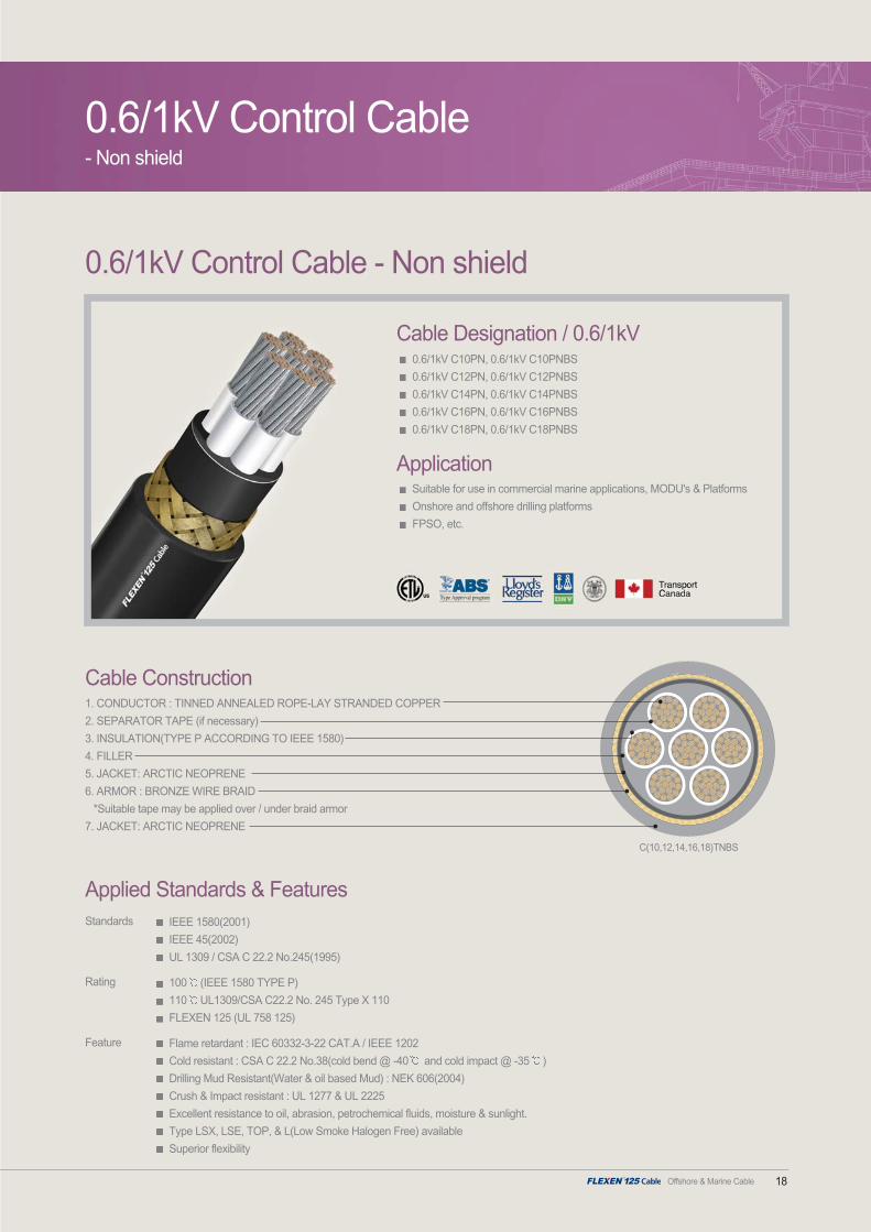
0.6/1kV Control Cable - Non shield
Cable Construction1. CONDUCTOR : TINNED ANNEALED ROPE-LAY STRANDED COPPER
2. SEPARATOR TAPE (if necessary)
3. INSULATION(TYPE P ACCORDING TO IEEE 1580)
4. FILLER
5. JACKET: ARCTIC NEOPRENE
6. ARMOR : BRONZE WIRE BRAID
*Suitable tape may be applied over / under braid armor
7. JACKET: ARCTIC NEOPRENE
C(10,12,14,16,18)TNBS
Cable Designation / 0.6/1kV0.6/1kV C10PN, 0.6/1kV C10PNBS
0.6/1kV C12PN, 0.6/1kV C12PNBS
0.6/1kV C14PN, 0.6/1kV C14PNBS
0.6/1kV C16PN, 0.6/1kV C16PNBS
0.6/1kV C18PN, 0.6/1kV C18PNBS
Application Suitable for use in commercial marine applications, MODU's & Platforms
Onshore and offshore drilling platforms
FPSO, etc.
Applied Standards & FeaturesIEEE 1580(2001)
IEEE 45(2002)
UL 1309 / CSA C 22.2 No.245(1995)
100 (IEEE 1580 TYPE P)
110 UL1309/CSA C22.2 No. 245 Type X 110
FLEXEN 125 (UL 758 125)
Standards
Rating
Flame retardant : IEC 60332-3-22 CAT.A / IEEE 1202
Cold resistant : CSA C 22.2 No.38(cold bend @ -40 and cold impact @ -35 )
Drilling Mud Resistant(Water & oil based Mud) : NEK 606(2004)
Crush & Impact resistant : UL 1277 & UL 2225
Excellent resistance to oil, abrasion, petrochemical fluids, moisture & sunlight.
Type LSX, LSE, TOP, & L(Low Smoke Halogen Free) available
Superior flexibility
Feature

19
600V Control Cable- Non shield
0.6/1kV C10PN, 0.6/1kV C10PNBS
No.
of coresConductor
size
AWG/MCM
CompostionConductor diameter
Nos/AWG mm inch
ConductorInsulationthickness
mm inch
Jacketthickness
mm
Sheaththickness
Unarmored
Overalldiameter
mm mm kg/km lbs/1000ftinch inchinch
Approx.Weight
Armor & Sheath
Overalldiameter
mm kg/km lbs/1000ftinch
Approx.Weight
0.6/1kV C12PN, 0.6/1kV C12PNBS
No.
of coresConductor
size
AWG/MCM
CompostionConductor diameter
Nos/AWG mm inch
ConductorInsulationthickness
mm inch
Jacketthickness
mm
Sheaththickness
Unarmored
Overalldiameter
mm mm kg/km lbs/1000ftinch inchinch
Approx.Weight
Armor & Sheath
Overalldiameter
mm kg/km lbs/1000ftinch
Approx.Weight

Offshore & Marine Cable 20
0.6/1kV C14PN, 0.6/1kV C14PNBS
No.
of coresConductor
size
AWG/MCM
CompostionConductor diameter
Nos/AWG mm inch
ConductorInsulationthickness
mm inch
Jacketthickness
mm
Sheaththickness
Unarmored
Overalldiameter
mm mm kg/km lbs/1000ftinch inchinch
Approx.Weight
Armor & Sheath
Overalldiameter
mm kg/km lbs/1000ftinch
Approx.Weight
0.6/1kV C16PN, 0.6/1kV C16PNBS
No.
of coresConductor
size
AWG/MCM
CompostionConductor diameter
Nos/AWG mm inch
ConductorInsulationthickness
mm inch
Jacketthickness
mm
Sheaththickness
Unarmored
Overalldiameter
mm mm kg/km lbs/1000ftinch inchinch
Approx.Weight
Armor & Sheath
Overalldiameter
mm kg/km lbs/1000ftinch
Approx.Weight

21
0.6/1kV C18PN, 0.6/1kV C18PNBS
No.
of coresConductor
size
AWG/MCM
CompostionConductor diameter
Nos/AWG mm inch
ConductorInsulationthickness
mm inch
Jacketthickness
mm
Sheaththickness
Unarmored
Overalldiameter
mm mm kg/km lbs/1000ftinch inchinch
Approx.Weight
Armor & Sheath
Overalldiameter
mm kg/km lbs/1000ftinch
Approx.Weight
600V Control Cable- Non shield

Offshore & Marine Cable 22
0.6/1kV Control Cable - With Overall Shield
Cable Construction
0.6/1kV Control Cable- With Overall Shield
Cable Designation / 0.6/1kV0.6/1kV C(OS)10PN, 0.6/1kV C(OS)10PNBS
0.6/1kV C(OS)12PN, 0.6/1kV C(OS)12PNBS
0.6/1kV C(OS)14PN, 0.6/1kV C(OS)14PNBS
0.6/1kV C(OS)16PN, 0.6/1kV C(OS)16PNBS
0.6/1kV C(OS)18PN, 0.6/1kV C(OS)18PNBS
0.6/1kV C(OS)20PN, 0.6/1kV C(OS)20PNBS
Application Suitable for use in commercial marine applications, MODU's & Platforms
Onshore and offshore drilling platforms
FPSO, etc.
1. CONDUCTOR : TINNED ANNEALED ROPE-LAY STRANDED COPPER
*For fire resisting cables, FS-type, mica tape shall be applied over the conductor as a fire proof layer
2. SEPARATOR TAPE (if necessary)
3. INSULATION(TYPE P ACCORDING TO IEEE 1580)
4. FILLER
5. SHIELDING: ALUMINUM POLYESTER TAPE
6. DRAIN WIRE
7. JACKET: ARCTIC NEOPRENE
8. ARMOR: BRONZE WIRE BRAID
9. JACKET: ARCTIC NEOPRENEC(OS)16,14,12,10PN
Applied Standards & FeaturesIEEE 1580(2001)
IEEE 45(2002)
UL 1309 / CSA C 22.2 No.245(1995)
100 (IEEE 1580 TYPE P)
110 UL1309/CSA C22.2 No. 245 Type X 110
FLEXEN 125 (UL 758 125)
Standards
Rating
Flame retardant : IEC 60332-3-22 CAT.A / IEEE 1202
Cold resistant : CSA C 22.2 No.38(cold bend @ -40 and cold impact @ -35 )
Drilling Mud Resistant(Water & oil based Mud) : NEK 606(2004)
Crush & Impact resistant : UL 1277 & UL 2225
Excellent resistance to oil, abrasion, petrochemical fluids, moisture & sunlight.
Type LSX, LSE, TOP, & L(Low Smoke Halogen Free) available
Superior flexibility
Feature
23
0.6/1kV Control Cable- With Overall Shield
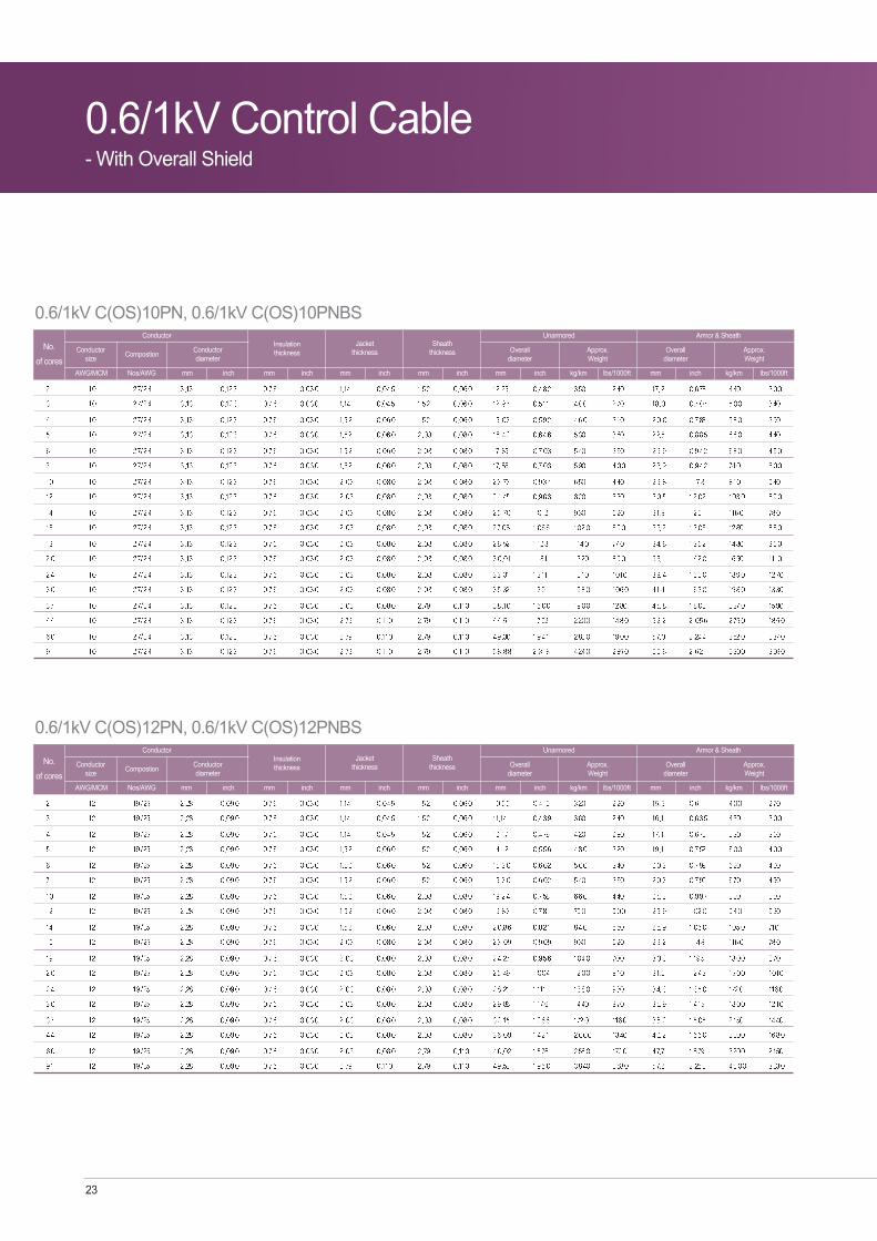
0.6/1kV C(OS)10PN, 0.6/1kV C(OS)10PNBS
No.
of coresConductor
size
AWG/MCM
CompostionConductor diameter
Nos/AWG mm inch
ConductorInsulationthickness
mm inch
Jacketthickness
mm
Sheaththickness
Unarmored
Overalldiameter
mm mm kg/km lbs/1000ftinch inchinch
Approx.Weight
Armor & Sheath
Overalldiameter
mm kg/km lbs/1000ftinch
Approx.Weight
0.6/1kV C(OS)12PN, 0.6/1kV C(OS)12PNBS
No.
of coresConductor
size
AWG/MCM
CompostionConductor diameter
Nos/AWG mm inch
ConductorInsulationthickness
mm inch
Jacketthickness
mm
Sheaththickness
Unarmored
Overalldiameter
mm mm kg/km lbs/1000ftinch inchinch
Approx.Weight
Armor & Sheath
Overalldiameter
mm kg/km lbs/1000ftinch
Approx.Weight
Offshore & Marine Cable 24
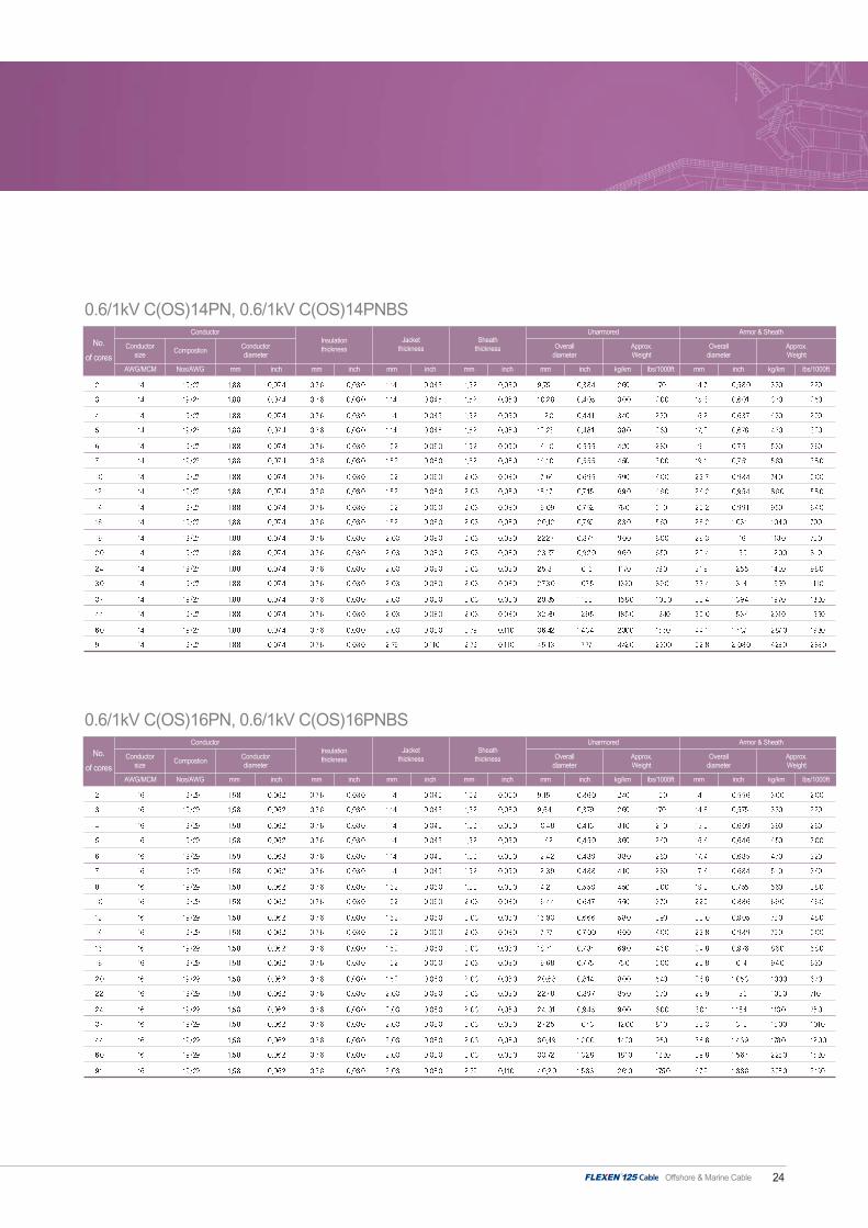
0.6/1kV C(OS)14PN, 0.6/1kV C(OS)14PNBS
No.
of coresConductor
size
AWG/MCM
CompostionConductor diameter
Nos/AWG mm inch
ConductorInsulationthickness
mm inch
Jacketthickness
mm
Sheaththickness
Unarmored
Overalldiameter
mm mm kg/km lbs/1000ftinch inchinch
Approx.Weight
Armor & Sheath
Overalldiameter
mm kg/km lbs/1000ftinch
Approx.Weight
0.6/1kV C(OS)16PN, 0.6/1kV C(OS)16PNBS
No.
of coresConductor
size
AWG/MCM
CompostionConductor diameter
Nos/AWG mm inch
ConductorInsulationthickness
mm inch
Jacketthickness
mm
Sheaththickness
Unarmored
Overalldiameter
mm mm kg/km lbs/1000ftinch inchinch
Approx.Weight
Armor & Sheath
Overalldiameter
mm kg/km lbs/1000ftinch
Approx.Weight

25
0.6/1kV C(OS)18PN, 0.6/1kV C(OS)18PNBS
No.
of coresConductor
size
AWG/MCM
CompostionConductor diameter
Nos/AWG mm inch
ConductorInsulationthickness
mm inch
Jacketthickness
mm
Sheaththickness
Unarmored
Overalldiameter
mm mm kg/km lbs/1000ftinch inchinch
Approx.Weight
Armor & Sheath
Overalldiameter
mm kg/km lbs/1000ftinch
Approx.Weight
0.6/1kV C(OS)20PN, 0.6/1kV C(OS)20PNBS
No.
of coresConductor
size
AWG/MCM
CompostionConductor diameter
Nos/AWG mm inch
ConductorInsulationthickness
mm inch
Jacketthickness
mm
Sheaththickness
Unarmored
Overalldiameter
mm mm kg/km lbs/1000ftinch inchinch
Approx.Weight
Armor & Sheath
Overalldiameter
mm kg/km lbs/1000ftinch
Approx.Weight
0.6/1kV Control Cable- With Overall Shield

Offshore & Marine Cable 26
0.6/1kV Control Cable- With Overall Braid Shield
0.6/1kV Control Cable - With Overall Braid Shield
Cable Construction
Cable Designation / 0.6/1kV0.6/1kV C(OBS)14PN, 0.6/1kV C(OBS)14PNBS
0.6/1kV C(OBS)16PN, 0.6/1kV C(OBS)16PNBS
0.6/1kV C(OBS)18PN, 0.6/1kV C(OBS)18PNBS
0.6/1kV C(OBS)20PN, 0.6/1kV C(OBS)20PNBS
Application Suitable for use in commercial marine applications, MODU's & Platforms
Onshore and offshore drilling platforms
FPSO, etc.
1. CONDUCTOR : TINNED ANNEALED ROPE-LAY STRANDED COPPER
*For fire resisting cables, FS-type, mica tape shall be applied over the conductor as a fire proof layer
2. SEPARATOR TAPE (if necessary)
3. INSULATION(TYPE P ACCORDING TO IEEE 1580)
4. FILLER
5. SHIELDING: TINNED COPPER WIRE BRAID
6. JACKET: ARCTIC NEOPRENE
7. ARMOR: BRONZE WIRE BRAID
8. JACKET: ARCTIC NEOPRENE C(OS)16,14.12,10PN
Applied Standards & FeaturesIEEE 1580(2001)
IEEE 45(2002)
UL 1309 / CSA C 22.2 No.245(1995)
100 (IEEE 1580 TYPE P)
110 UL1309/CSA C22.2 No. 245 Type X 110
FLEXEN 125 (UL 758 125)
Standards
Rating
Flame retardant : IEC 60332-3-22 CAT.A / IEEE 1202
Cold resistant : CSA C 22.2 No.38(cold bend @ -40 and cold impact @ -35 )
Drilling Mud Resistant(Water & oil based Mud) : NEK 606(2004)
Crush & Impact resistant : UL 1277 & UL 2225
Excellent resistance to oil, abrasion, petrochemical fluids, moisture & sunlight.
Type LSX, LSE, TOP, & L(Low Smoke Halogen Free) available
Superior flexibility
Feature

27
0.6/1kV Control Cable- With Overall Braid Shield
0.6/1kV C(OBS)14PN, 0.6/1kV C(OBS)14PNBS
No.
of coresConductor
size
AWG/MCM
CompostionConductor diameter
Nos/AWG mm inch
ConductorInsulationthickness
mm inch
Jacketthickness
mm
Sheaththickness
Unarmored
Overalldiameter
mm mm kg/km lbs/1000ftinch inchinch
Approx.Weight
Armor & Sheath
Overalldiameter
mm kg/km lbs/1000ftinch
Approx.Weight
0.6/1kV C(OBS)16PN, 0.6/1kV C(OBS)16PNBS
No.
of coresConductor
size
AWG/MCM
CompostionConductor diameter
Nos/AWG mm inch
ConductorInsulationthickness
mm inch
Jacketthickness
mm
Sheaththickness
Unarmored
Overalldiameter
mm mm kg/km lbs/1000ftinch inchinch
Approx.Weight
Armor & Sheath
Overalldiameter
mm kg/km lbs/1000ftinch
Approx.Weight

Offshore & Marine Cable 28
0.6/1kV C(OBS)18PN, 0.6/1kV C(OBS)18PNBS
No.
of coresConductor
size
AWG/MCM
CompostionConductor diameter
Nos/AWG mm inch
ConductorInsulationthickness
mm inch
Jacketthickness
mm
Sheaththickness
Unarmored
Overalldiameter
mm mm kg/km lbs/1000ftinch inchinch
Approx.Weight
Armor & Sheath
Overalldiameter
mm kg/km lbs/1000ftinch
Approx.Weight
0.6/1kV C(OBS)20PN, 0.6/1kV C(OBS)20PNBS
No.
of coresConductor
size
AWG/MCM
CompostionConductor diameter
Nos/AWG mm inch
ConductorInsulationthickness
mm inch
Jacketthickness
mm
Sheaththickness
Unarmored
Overalldiameter
mm mm kg/km lbs/1000ftinch inchinch
Approx.Weight
Armor & Sheath
Overalldiameter
mm kg/km lbs/1000ftinch
Approx.Weight

29
0.6/1kV Signal Cable0.6/1kV Signal Cable - Overall Braid Shield
0.6/1kV Signal Cable - Overall Shield
0.6/1kV Signal Cable - Individual Shield
0.6/1kV Signal Cable - Individual & Overall Shield

0.6/1kV Signal Cable- With Overall Shield
0.6/1kV Signal Cable - With Overall Shield
Cable Construction1. CONDUCTOR : TINNED ANNEALED ROPE-LAY STRANDED COPPER
2. SEPARATOR TAPE (if necessary)
3. INSULATION(TYPE P ACCORDING TO IEEE 1580)
4. FILLER
5. BINDER TAPE
6. DRAIN WIRE
7. SHIELDING : ALUMINUM POLYESTER TAPE
8. JACKET : ARCTIC NEOPRENE
9. ARMOR : BRONZE WIRE BRAID
*Suitable tape may be applied over/under braid armor
10. JACKET : ARCTIC NEOPRENE
TP(OS)14,16,18PNBS
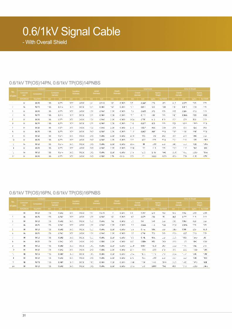
Cable Designation / 0.6/1kV0.6/1kV TP(OS)14PN, 0.6/1kV TP(OS)14PNBS
0.6/1kV TP(OS)16PN, 0.6/1kV TP(OS)16PNBS
0.6/1kV TP(OS)18PN, 0.6/1kV TP(OS)18PNBS
0.6/1kV TP(OS)20PN, 0.6/1kV TP(OS)20PNBS
0.6/1kV TP(OS)22PN, 0.6/1kV TP(OS)22PNBS
0.6/1kV TT(OS)16PN, 0.6/1kV TT(OS)16PNBS
0.6/1kV TT(OS)18PN, 0.6/1kV TT(OS)18PNBS
0.6/1kV TT(OS)20PN, 0.6/1kV TT(OS)20PNBS
Application Suitable for use in commercial marine applications, MODU's & Platforms
Onshore and offshore drilling platforms
FPSO, etc.
Offshore & Marine Cable 30
Applied Standards & FeaturesIEEE 1580(2001)
IEEE 45(2002)
UL 1309 / CSA C 22.2 No.245(1995)
100 (IEEE 1580 TYPE P)
110 UL1309/CSA C22.2 No. 245 Type X 110
FLEXEN 125 (UL 758 125)
Standards
Rating
Flame retardant : IEC 60332-3-22 CAT.A / IEEE 1202
Cold resistant : CSA C 22.2 No.38(cold bend @ -40 and cold impact @ -35 )
Drilling Mud Resistant(Water & oil based Mud) : NEK 606(2004)
Crush & Impact resistant : UL 1277 & UL 2225
Excellent resistance to oil, abrasion, petrochemical fluids, moisture & sunlight.
Type LSX, LSE, TOP, & L(Low Smoke Halogen Free) available
Superior flexibility
Feature
31
0.6/1kV Signal Cable- With Overall Shield
0.6/1kV TP(OS)14PN, 0.6/1kV TP(OS)14PNBS
No.
of pairsConductor
size
AWG/MCM
CompostionConductor diameter
Nos/AWG mm inch
ConductorInsulationthickness
mm inch
Jacketthickness
mm
Sheaththickness
Unarmored
Overalldiameter
mm mm kg/km lbs/1000ftinch inchinch
Approx.Weight
Armor & Sheath
Overalldiameter
mm kg/km lbs/1000ftinch
Approx.Weight
0.6/1kV TP(OS)16PN, 0.6/1kV TP(OS)16PNBS
No.
of pairsConductor
size
AWG/MCM
CompostionConductor diameter
Nos/AWG mm inch
ConductorInsulationthickness
mm inch
Jacketthickness
mm
Sheaththickness
Unarmored
Overalldiameter
mm mm kg/km lbs/1000ftinch inchinch
Approx.Weight
Armor & Sheath
Overalldiameter
mm kg/km lbs/1000ftinch
Approx.Weight

Offshore & Marine Cable 32
0.6/1kV TP(OS)18PN, 0.6/1kV TP(OS)18PNBS
No.
of pairsConductor
size
AWG/MCM
CompostionConductor diameter
Nos/AWG mm inch
ConductorInsulationthickness
mm inch
Jacketthickness
mm
Sheaththickness
Unarmored
Overalldiameter
mm mm kg/km lbs/1000ftinch inchinch
Approx.Weight
Armor & Sheath
Overalldiameter
mm kg/km lbs/1000ftinch
Approx.Weight
0.6/1kV TP(OS)20PN, 0.6/1kV TP(OS)20PNBS
No.
of pairsConductor
size
AWG/MCM
CompostionConductor diameter
Nos/AWG mm inch
ConductorInsulationthickness
mm inch
Jacketthickness
mm
Sheaththickness
Unarmored
Overalldiameter
mm mm kg/km lbs/1000ftinch inchinch
Approx.Weight
Armor & Sheath
Overalldiameter
mm kg/km lbs/1000ftinch
Approx.Weight

33
0.6/1kV Signal Cable- With Overall Shield
0.6/1kV TP(OS)22PN, 0.6/1kV TP(OS)22PNBS
No.
of pairsConductor
size
AWG/MCM
CompostionConductor diameter
Nos/AWG mm inch
ConductorInsulationthickness
mm inch
Jacketthickness
mm
Sheaththickness
Unarmored
Overalldiameter
mm mm kg/km lbs/1000ftinch inchinch
Approx.Weight
Armor & Sheath
Overalldiameter
mm kg/km lbs/1000ftinch
Approx.Weight
0.6/1KV TT(OS)16PN, 0.6/1KV TT(OS)16PNBS
No.
of triadsConductor
size
AWG/MCM
CompostionConductor diameter
Nos/AWG mm inch
ConductorInsulationthickness
mm inch
Jacketthickness
mm
Sheaththickness
Unarmored
Overalldiameter
mm mm kg/km lbs/1000ftinch inchinch
Approx.Weight
Armor & Sheath
Overalldiameter
mm kg/km lbs/1000ftinch
Approx.Weight

Offshore & Marine Cable 34
0.6/1kV TT(OS)18PN, 0.6/1kV TT(OS)18PNBS
No.
of triadsConductor
size
AWG/MCM
CompostionConductor diameter
Nos/AWG mm inch
ConductorInsulationthickness
mm inch
Jacketthickness
mm
Sheaththickness
Unarmored
Overalldiameter
mm mm kg/km lbs/1000ftinch inchinch
Approx.Weight
Armor & Sheath
Overalldiameter
mm kg/km lbs/1000ftinch
Approx.Weight
0.6/1kV TT(OS)20PN, 0.6/1kV TT(OS)20PNBS
No.
of triadsConductor
size
AWG/MCM
CompostionConductor diameter
Nos/AWG mm inch
ConductorInsulationthickness
mm inch
Jacketthickness
mm
Sheaththickness
Unarmored
Overalldiameter
mm mm kg/km lbs/1000ftinch inchinch
Approx.Weight
Armor & Sheath
Overalldiameter
mm kg/km lbs/1000ftinch
Approx.Weight
35
0.6/1kV Signal Cable- With Overall Braid Shield Pair Twisted
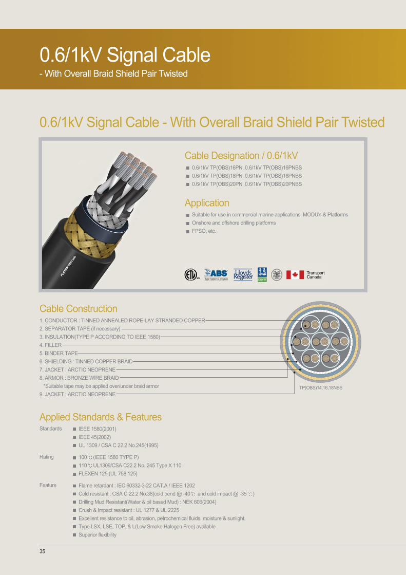
0.6/1kV Signal Cable - With Overall Braid Shield Pair Twisted
Cable Construction1. CONDUCTOR : TINNED ANNEALED ROPE-LAY STRANDED COPPER
2. SEPARATOR TAPE (if necessary)
3. INSULATION(TYPE P ACCORDING TO IEEE 1580)
4. FILLER
5. BINDER TAPE
6. SHIELDING : TINNED COPPER BRAID
7. JACKET : ARCTIC NEOPRENE
8. ARMOR : BRONZE WIRE BRAID
*Suitable tape may be applied over/under braid armor
9. JACKET : ARCTIC NEOPRENETP(OBS)14,16,18NBS
Cable Designation / 0.6/1kV0.6/1kV TP(OBS)16PN, 0.6/1kV TP(OBS)16PNBS
0.6/1kV TP(OBS)18PN, 0.6/1kV TP(OBS)18PNBS
0.6/1kV TP(OBS)20PN, 0.6/1kV TP(OBS)20PNBS
Application Suitable for use in commercial marine applications, MODU's & Platforms
Onshore and offshore drilling platforms
FPSO, etc.
Applied Standards & FeaturesIEEE 1580(2001)
IEEE 45(2002)
UL 1309 / CSA C 22.2 No.245(1995)
100 (IEEE 1580 TYPE P)
110 UL1309/CSA C22.2 No. 245 Type X 110
FLEXEN 125 (UL 758 125)
Standards
Rating
Flame retardant : IEC 60332-3-22 CAT.A / IEEE 1202
Cold resistant : CSA C 22.2 No.38(cold bend @ -40 and cold impact @ -35 )
Drilling Mud Resistant(Water & oil based Mud) : NEK 606(2004)
Crush & Impact resistant : UL 1277 & UL 2225
Excellent resistance to oil, abrasion, petrochemical fluids, moisture & sunlight.
Type LSX, LSE, TOP, & L(Low Smoke Halogen Free) available
Superior flexibility
Feature

Offshore & Marine Cable 36
0.6/1kV TP(OBS)16PN, 0.6/1kV TP(OBS)16PNBS
No.
of pairsConductor
size
AWG/MCM
CompostionConductor diameter
Nos/AWG mm inch
ConductorInsulationthickness
mm inch
Jacketthickness
mm
Sheaththickness
Unarmored
Overalldiameter
mm mm kg/km lbs/1000ftinch inchinch
Approx.Weight
Armor & Sheath
Overalldiameter
mm kg/km lbs/1000ftinch
Approx.Weight
0.6/1kV TP(OBS)18PN, 0.6/1kV TP(OBS)18PNBS
No.
of pairsConductor
size
AWG/MCM
CompostionConductor diameter
Nos/AWG mm inch
ConductorInsulationthickness
mm inch
Jacketthickness
mm
Sheaththickness
Unarmored
Overalldiameter
mm mm kg/km lbs/1000ftinch inchinch
Approx.Weight
Armor & Sheath
Overalldiameter
mm kg/km lbs/1000ftinch
Approx.Weight

37
0.6/1kV TP(OBS)20PN, 0.6/1kV TP(OBS)20PNBS
No.
of pairsConductor
size
AWG/MCM
CompostionConductor diameter
Nos/AWG mm inch
ConductorInsulationthickness
mm inch
Jacketthickness
mm
Sheaththickness
Unarmored
Overalldiameter
mm mm kg/km lbs/1000ftinch inchinch
Approx.Weight
Armor & Sheath
Overalldiameter
mm kg/km lbs/1000ftinch
Approx.Weight
0.6/1kV Signal Cable- With Overall Braid Shield Pair Twisted

Offshore & Marine Cable 38
0.6/1kV Signal Cable - With Individual Shield Pair Twisted
0.6/1kV Signal Cable - With Individual Shield Pair Twisted
Cable Contruction1. CONDUCTOR : TINNED ANNEALED ROPE-LAY STRANDED COPPER
2. SEPARATOR TAPE (if necessary)
3. INSULATION(TYPE P ACCORDING TO IEEE 1580)
4. BINDER TAPE
5. DRAIN WIRE
6. SHIELDING : ALUMINUM POLYESTER TAPE
7. FILLER
8. JACKET : ARCTIC NEOPRENE
9. ARMOR : BRONZE WIRE BRAID
*Suitable tape may be applied over/under braid armor
10. JACKET : ARCTIC NEOPRENE
TP(I/S)16PNBS
Cable Designation / 0.6/1kkV0.6/1kV TP(I/S)14PN, 0.6/1kV TP(I/S)14PNBS
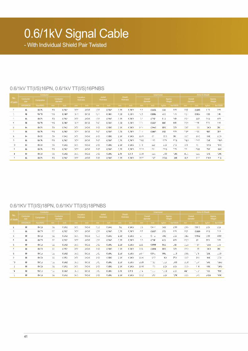
0.6/1kV TP(I/S)16PN, 0.6/1kV TP(I/S)16PNBS
0.6/1kV TP(I/S)18PN, 0.6/1kV TP(I/S)18PNBS
0.6/1kV TP(I/S)20PN, 0.6/1kV TP(I/S)20PNBS
0.6/1kV TT(I/S)16PN, 0.6/1kV TT(I/S)16PNBS
0.6/1kV TT(I/S)18PN, 0.6/1kV TT(I/S)18PNBS
0.6/1kV TT(I/S)20PN, 0.6/1kV TT(I/S)20PNBS
Application Suitable for use in commercial marine applications, MODU's & Platforms
Onshore and offshore drilling platforms
FPSO, etc.
Applied Standards & FeaturesIEEE 1580(2001)
IEEE 45(2002)
UL 1309 / CSA C 22.2 No.245(1995)
100 (IEEE 1580 TYPE P)
110 UL1309/CSA C22.2 No. 245 Type X 110
FLEXEN 125 (UL 758 125)
Standards
Rating
Flame retardant : IEC 60332-3-22 CAT.A / IEEE 1202
Cold resistant : CSA C 22.2 No.38(cold bend @ -40 and cold impact @ -35 )
Drilling Mud Resistant(Water & oil based Mud) : NEK 606(2004)
Crush & Impact resistant : UL 1277 & UL 2225
Excellent resistance to oil, abrasion, petrochemical fluids, moisture & sunlight.
Type LSX, LSE, TOP, & L(Low Smoke Halogen Free) available
Superior flexibility
Feature

39
0.6/1kV Signal Cable - With Individual Shield Pair Twisted
0.6/1kV TP(I/S)14PN, 0.6/1kV TP(I/S)14PNBS
No.
of pairsConductor
size
AWG/MCM
CompostionConductor diameter
Nos/AWG mm inch
ConductorInsulationthickness
mm inch
Jacketthickness
mm
Sheaththickness
Unarmored
Overalldiameter
mm mm kg/km lbs/1000ftinch inchinch
Approx.Weight
Armor & Sheath
Overalldiameter
mm kg/km lbs/1000ftinch
Approx.Weight
0.6/1kV TP(I/S)16PN, 0.6/1kV TP(I/S)16PNBS
No.
of pairsConductor
size
AWG/MCM
CompostionConductor diameter
Nos/AWG mm inch
ConductorInsulationthickness
mm inch
Jacketthickness
mm
Sheaththickness
Unarmored
Overalldiameter
mm mm kg/km lbs/1000ftinch inchinch
Approx.Weight
Armor & Sheath
Overalldiameter
mm kg/km lbs/1000ftinch
Approx.Weight

Offshore & Marine Cable 40
0.6/1kV TP(I/S)18PN, 0.6/1kV TP(I/S)18PNBS
No.
of pairsConductor
size
AWG/MCM
CompostionConductor diameter
Nos/AWG mm inch
ConductorInsulationthickness
mm inch
Jacketthickness
mm
Sheaththickness
Unarmored
Overalldiameter
mm mm kg/km lbs/1000ftinch inchinch
Approx.Weight
Armor & Sheath
Overalldiameter
mm kg/km lbs/1000ftinch
Approx.Weight
0.6/1kV TP(I/S)20PN, 0.6/1kV TP(I/S)20PNBS
No.
of pairsConductor
size
AWG/MCM
CompostionConductor diameter
Nos/AWG mm inch
ConductorInsulationthickness
mm inch
Jacketthickness
mm
Sheaththickness
Unarmored
Overalldiameter
mm mm kg/km lbs/1000ftinch inchinch
Approx.Weight
Armor & Sheath
Overalldiameter
mm kg/km lbs/1000ftinch
Approx.Weight
41
0.6/1kV Signal Cable - With Individual Shield Pair Twisted
0.6/1kV TT(I/S)16PN, 0.6/1kV TT(I/S)16PNBS
No.
of pairsConductor
size
AWG/MCM
CompostionConductor diameter
Nos/AWG mm inch
ConductorInsulationthickness
mm inch
Jacketthickness
mm
Sheaththickness
Unarmored
Overalldiameter
mm mm kg/km lbs/1000ftinch inchinch
Approx.Weight
Armor & Sheath
Overalldiameter
mm kg/km lbs/1000ftinch
Approx.Weight
0.6/1KV TT(I/S)18PN, 0.6/1KV TT(I/S)18PNBS
No.
of triadsConductor
size
AWG/MCM
CompostionConductor diameter
Nos/AWG mm inch
ConductorInsulationthickness
mm inch
Jacketthickness
mm
Sheaththickness
Unarmored
Overalldiameter
mm mm kg/km lbs/1000ftinch inchinch
Approx.Weight
Armor & Sheath
Overalldiameter
mm kg/km lbs/1000ftinch
Approx.Weight

Offshore & Marine Cable 42
0.6/1kV TT(I/S)20PN, 0.6/1kV TT(I/S)20PNBS
No.
of triadsConductor
size
AWG/MCM
CompostionConductor diameter
Nos/AWG mm inch
ConductorInsulationthickness
mm inch
Jacketthickness
mm
Sheaththickness
Unarmored
Overalldiameter
mm mm kg/km lbs/1000ftinch inchinch
Approx.Weight
Armor & Sheath
Overalldiameter
mm kg/km lbs/1000ftinch
Approx.Weight

43
0.6/1kV Signal Cable- With Individual & Overall Shield
0.6/1kV Signal Cable - With Individual & Overall Shield
Cable Construction1. CONDUCTOR : TINNED ANNEALED ROPE-LAY STRANDED COPPER
2. SEPARATOR TAPE (if necessary)
3. INSULATION(TYPE P ACCORDING TO IEEE 1580)
4. BINDER TAPE
5. DRAIN WIRE
6. SHIELDING : ALUMINUM POLYSTER TAPE
7. FILLER
8. JACKET : ARCTIC NEOPRENE
9. ARMOR : BRONZE WIRE BRAID
*Suitable tape may be applied over/under braid armor
10. JACKET : ARCTIC NEOPRENE
TP(I/S-OS)16,18,20PNBS
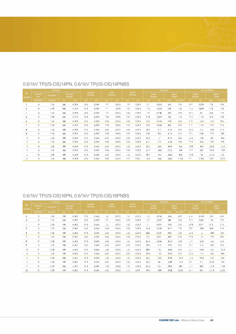
Cable Designation / 0.6/1kV0.6/1kV TP(I/S-OS)14PN, 0.6/1kV TP(I/S-OS)14PNBS
0.6/1kV TP(I/S-OS)16PN, 0.6/1kV TP(I/S-OS)16PNBS
0.6/1kV TP(I/S-OS)18PN, 0.6/1kV TP(I/S-OS)18PNBS
0.6/1kV TP(I/S-OS)20PN, 0.6/1kV TP(I/S-OS)20PNBS
0.6/1kV TT(I/S-OS)16PN, 0.6/1kV TT(I/S-OS)16PNBS
0.6/1kV TT(I/S-OS)18PN, 0.6/1kV TT(I/S-OS)18PNBS
0.6/1kV TT(I/S-OS)20PN, 0.6/1kV TT(I/S-OS)20PNBS
Application Suitable for use in commercial marine applications, MODU's & Platforms
Onshore and offshore drilling platforms
FPSO, etc.
Applied Standards & FeaturesIEEE 1580(2001)
IEEE 45(2002)
UL 1309 / CSA C 22.2 No.245(1995)
100 (IEEE 1580 TYPE P)
110 UL1309/CSA C22.2 No. 245 Type X 110
FLEXEN 125 (UL 758 125)
Standards
Rating
Flame retardant : IEC 60332-3-22 CAT.A / IEEE 1202
Cold resistant : CSA C 22.2 No.38(cold bend @ -40 and cold impact @ -35 )
Drilling Mud Resistant(Water & oil based Mud) : NEK 606(2004)
Crush & Impact resistant : UL 1277 & UL 2225
Excellent resistance to oil, abrasion, petrochemical fluids, moisture & sunlight.
Type LSX, LSE, TOP, & L(Low Smoke Halogen Free) available
Superior flexibility
Feature
Offshore & Marine Cable 44
0.6/1kV TP(I/S-OS)14PN, 0.6/1kV TP(I/S-OS)14PNBS
No.
of pairsConductor
size
AWG/MCM
CompostionConductor diameter
Nos/AWG mm inch
ConductorInsulationthickness
mm inch
Jacketthickness
mm
Sheaththickness
Unarmored
Overalldiameter
mm mm kg/km lbs/1000ftinch inchinch
Approx.Weight
Armor & Sheath
Overalldiameter
mm kg/km lbs/1000ftinch
Approx.Weight
0.6/1kV TP(I/S-OS)16PN, 0.6/1kV TP(I/S-OS)16PNBS
No.
of pairsConductor
size
AWG/MCM
CompostionConductor diameter
Nos/AWG mm inch
ConductorInsulationthickness
mm inch
Jacketthickness
mm
Sheaththickness
Unarmored
Overalldiameter
mm mm kg/km lbs/1000ftinch inchinch
Approx.Weight
Armor & Sheath
Overalldiameter
mm kg/km lbs/1000ftinch
Approx.Weight

45
0.6/1kV Signal Cable- With Individual & Overall Shield
0.6/1kV TP(I/S-OS)18PN, 0.6/1kV TP(I/S-OS)18PNBS
No.
of pairsConductor
size
AWG/MCM
CompostionConductor diameter
Nos/AWG mm inch
ConductorInsulationthickness
mm inch
Jacketthickness
mm
Sheaththickness
Unarmored
Overalldiameter
mm mm kg/km lbs/1000ftinch inchinch
Approx.Weight
Armor & Sheath
Overalldiameter
mm kg/km lbs/1000ftinch
Approx.Weight
0.6/1kV TP(I/S-OS)20PN, 0.6/1kV TP(I/S-OS)20PNBS
No.
of pairsConductor
size
AWG/MCM
CompostionConductor diameter
Nos/AWG mm inch
ConductorInsulationthickness
mm inch
Jacketthickness
mm
Sheaththickness
Unarmored
Overalldiameter
mm mm kg/km lbs/1000ftinch inchinch
Approx.Weight
Armor & Sheath
Overalldiameter
mm kg/km lbs/1000ftinch
Approx.Weight

Offshore & Marine Cable 46
0.6/1kV TT(I/S-OS)16PN, 0.6/1kV TT(I/S-OS)16PNBS
No.
of triadsConductor
size
AWG/MCM
CompostionConductor diameter
Nos/AWG mm inch
ConductorInsulationthickness
mm inch
Jacketthickness
mm
Sheaththickness
Unarmored
Overalldiameter
mm mm kg/km lbs/1000ftinch inchinch
Approx.Weight
Armor & Sheath
Overalldiameter
mm kg/km lbs/1000ftinch
Approx.Weight
0.6/1kV TT(I/S-OS)18PN, 0.6/1kV TT(I/S-OS)18PNBS
No.
of triadsConductor
size
AWG/MCM
CompostionConductor diameter
Nos/AWG mm inch
ConductorInsulationthickness
mm inch
Jacketthickness
mm
Sheaththickness
Unarmored
Overalldiameter
mm mm kg/km lbs/1000ftinch inchinch
Approx.Weight
Armor & Sheath
Overalldiameter
mm kg/km lbs/1000ftinch
Approx.Weight
0.6/1kV TT(I/S-OS)20PN, 0.6/1kV TT(I/S-OS)20PNBS
No.
of triadsConductor
size
AWG/MCM
CompostionConductor diameter
Nos/AWG mm inch
ConductorInsulationthickness
mm inch
Jacketthickness
mm
Sheaththickness
Unarmored
Overalldiameter
mm mm kg/km lbs/1000ftinch inchinch
Approx.Weight
Armor & Sheath
Overalldiameter
mm kg/km lbs/1000ftinch
Approx.Weight

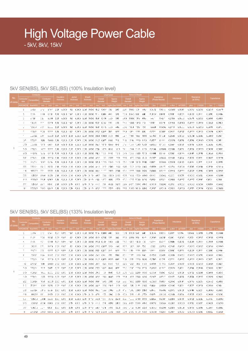
High Voltage Power CableHigh Voltage Power Cable- 5kV, 8kV, 15kV

Offshore & Marine Cable 48
High Voltage Power Cable - 5kV, 8kv, 15kV
Cable Construction1. CONDUCTOR : TINNED ANNEALED ROPE-LAY STRANDED COPPER
2. CONDUCTOR SHIELDING : SEMI-CONDUCTIING TAPE AND COMPOUND
3. INSULATION : ERR(ETHYLENE PROPYLENE RUBBER)
4. INSULATION SHIELD(NON-METALLIC MATERIAL : SEMI-CONDUCTING TAPE/COMPOUND)
5. INSULATION SHIELD(METAILIC) : TINNED COPPER WIRE BRAID
6. JACKET: ARCTIC NEOPRENE
7. ARMOR : BRONZE WIRE BRAID
8. OUTER JAKET : ARCTIC NEOPRRENE
5kV/8kV/15kV TENBS
Cable Designation / 5kV,8kV,15kV5kV SEN(BS), (100%, 133% Insulation level)
5kV TEN(BS), (100%, 133% Insulation level)
8kV SEN(BS), (100%, 133% Insulation level)
8kV TEN(BS), (100%, 133% Insulation level)
15kV SEN(BS), (100%, 133% Insulation level)
15kV TEN(BS), (100%, 133% Insulation level)
Application Suitable for use in commercial marine applications, MODU's & Platforms
Onshore and offshore drilling platforms
FPSO, etc.
High Voltage Power Cable- 5kV, 8kV, 15kV
Applied Standards & FeaturesIEEE 1580(2001)
IEEE 45(2002)
UL 1309 / CSA C 22.2 No.245(1995)
100 (IEEE 1580 TYPE P)
110 UL1309/CSA C22.2 No. 245 Type X 110
FLEXEN 125 (UL 758 125)
Standards
Rating
Flame retardant : IEC 60332-3-22 CAT.A / IEEE 1202
Cold resistant : CSA C 22.2 No.38(cold bend @ -40 and cold impact @ -35 )
Drilling Mud Resistant(Water & oil based Mud) : NEK 606(2004)
Crush & Impact resistant : UL 1277 & UL 2225
Excellent resistance to oil, abrasion, petrochemical fluids, moisture & sunlight.
Type LSX, LSE, TOP, & L(Low Smoke Halogen Free) available
Superior flexibility
Feature
49
High Voltage Power Cable- 5kV, 8kV, 15kV
No.
of coresConductor
size
5kV SEN(BS), 5kV SEL(BS) (100% Insulation level)
AWG/MCM
CompositionConductordiameter
Nos/AWG mm inch
Insulationthickness
mm inch
Jacketthickness
Sheaththickness
mm
Impedance(Phase-Neutral)
/km /1000ftinch mm inch
Conductor
Overalldiameter
mm kg/kminch
ApproxWeight
lbs/1000ft
Unarmored
Overalldiameter
mm inch
ApproxWeight
lbs/1000ft
Armor & Sheath
Inductance
/km /1000ft
Reactance(at 50Hz)
/km /1000ft
Capacitance
/km /1000ftkg/km
1
No.
of coresConductor
size
5kV SEN(BS), 5kV SEL(BS) (133% Insulation level)
AWG/MCM
CompositionConductordiameter
Nos/AWG mm inch
Insulationthickness
mm inch
Jacketthickness
Sheaththickness
mm
Impedance(Phase-Neutral)
/km /1000ftinch mm inch
Conductor
Overalldiameter
mm kg/kminch
ApproxWeight
lbs/1000ft
Unarmored
Overalldiameter
mm inch
ApproxWeight
lbs/1000ft
Armor & Sheath
Inductance
/km /1000ft
Reactance(at 50Hz)
/km /1000ft
Capacitance
/km /1000ftkg/km
1

Offshore & Marine Cable 50
No.
of coresConductor
size
5kV TEN(BS), 5kV TEL(BS) (100% Insulation level)
AWG/MCM
CompositionConductordiameter
Nos/AWG mm inch
Insulationthickness
mm inch
Jacketthickness
Sheaththickness
mm
Impedance(Phase-Neutral)
/km /1000ftinch mm inch
Conductor
Overalldiameter
mm kg/kminch
ApproxWeight
lbs/1000ft
Unarmored
Overalldiameter
mm inch
ApproxWeight
lbs/1000ft
Armor & Sheath
Inductance
/km /1000ft
Reactance(at 50Hz)
/km /1000ft
Capacitance
/km /1000ftkg/km
No.
of coresConductor
size
5kV TEN(BS), 5kV TEL(BS) (133% Insulation level)
AWG/MCM
CompositionConductordiameter
Nos/AWG mm inch
Insulationthickness
mm inch
Jacketthickness
Sheaththickness
mm
Impedance(Phase-Neutral)
/km /1000ftinch mm inch
Conductor
Overalldiameter
mm kg/kminch
ApproxWeight
lbs/1000ft
Unarmored
Overalldiameter
mm inch
ApproxWeight
lbs/1000ft
Armor & Sheath
Inductance
/km /1000ft
Reactance(at 50Hz)
/km /1000ft
Capacitance
/km /1000ftkg/km
3
3

51
High Voltage Power Cable- 5kV, 8kV, 15kV
No.
of coresConductor
size
8kV SEN(BS), 8kV SEL(BS) (100% Insulation level)
AWG/MCM
CompositionConductordiameter
Nos/AWG mm inch
Insulationthickness
mm inch
Jacketthickness
Sheaththickness
mm
Impedance(Phase-Neutral)
/km /1000ftinch mm inch
Conductor
Overalldiameter
mm kg/kminch
ApproxWeight
lbs/1000ft
Unarmored
Overalldiameter
mm inch
ApproxWeight
lbs/1000ft
Armor & Sheath
Inductance
/km /1000ft
Reactance(at 50Hz)
/km /1000ft
Capacitance
/km /1000ftkg/km
No.
of coresConductor
size
8kV SEN(BS), 8kV SEL(BS) (133% Insulation level)
AWG/MCM
CompositionConductordiameter
Nos/AWG mm inch
Insulationthickness
mm inch
Jacketthickness
Sheaththickness
mm
Impedance(Phase-Neutral)
/km /1000ftinch mm inch
Conductor
Overalldiameter
mm kg/kminch
ApproxWeight
lbs/1000ft
Unarmored
Overalldiameter
mm inch
ApproxWeight
lbs/1000ft
Armor & Sheath
Inductance
/km /1000ft
Reactance(at 50Hz)
/km /1000ft
Capacitance
/km /1000ftkg/km
1
1

Offshore & Marine Cable 52
No.
of coresConductor
size
8kV TEN(BS), 8kV TEL(BS) (100% Insulation level)
AWG/MCM
CompositionConductordiameter
Nos/AWG mm inch
Insulationthickness
mm inch
Jacketthickness
Sheaththickness
mm
Impedance(Phase-Neutral)
/km /1000ftinch mm inch
Conductor
Overalldiameter
mm kg/kminch
ApproxWeight
lbs/1000ft
Unarmored
Overalldiameter
mm inch
ApproxWeight
lbs/1000ft
Armor & Sheath
Inductance
/km /1000ft
Reactance(at 50Hz)
/km /1000ft
Capacitance
/km /1000ftkg/km
No.
of coresConductor
size
8kV TEN(BS), 8kV TEL(BS) (133% Insulation level)
AWG/MCM
CompositionConductordiameter
Nos/AWG mm inch
Insulationthickness
mm inch
Jacketthickness
Sheaththickness
mm
Impedance(Phase-Neutral)
/km /1000ftinch mm inch
Conductor
Overalldiameter
mm kg/kminch
ApproxWeight
lbs/1000ft
Unarmored
Overalldiameter
mm inch
ApproxWeight
lbs/1000ft
Armor & Sheath
Inductance
/km /1000ft
Reactance(at 50Hz)
/km /1000ft
Capacitance
/km /1000ftkg/km
3
3

53
High Voltage Power Cable- 5kV, 8kV, 15kV
No.
of coresConductor
size
15kV SEN(BS), 15kV SEL(BS) (100% Insulation level)
AWG/MCM
CompositionConductordiameter
Nos/AWG mm inch
Insulationthickness
mm inch
Jacketthickness
Sheaththickness
mm
Impedance(Phase-Neutral)
/km /1000ftinch mm inch
Conductor
Overalldiameter
mm kg/kminch
ApproxWeight
lbs/1000ft
Unarmored
Overalldiameter
mm inch
ApproxWeight
lbs/1000ft
Armor & Sheath
Inductance
/km /1000ft
Reactance(at 50Hz)
/km /1000ft
Capacitance
/km /1000ftkg/km
No.
of coresConductor
size
15kV SEN(BS), 15kV SEL(BS) (133% Insulation level)
AWG/MCM
CompositionConductordiameter
Nos/AWG mm inch
Insulationthickness
mm inch
Jacketthickness
Sheaththickness
mm
Impedance(Phase-Neutral)
/km /1000ftinch mm inch
Conductor
Overalldiameter
mm kg/kminch
ApproxWeight
lbs/1000ft
Unarmored
Overalldiameter
mm inch
ApproxWeight
lbs/1000ft
Armor & Sheath
Inductance
/km /1000ft
Reactance(at 50Hz)
/km /1000ft
Capacitance
/km /1000ftkg/km
1
1

Offshore & Marine Cable 54
No.
of coresConductor
size
15kV TEN(BS), 15kV TEL(BS) (100% Insulation level)
AWG/MCM
CompositionConductordiameter
Nos/AWG mm inch
Insulationthickness
mm inch
Jacketthickness
Sheaththickness
mm
Impedance(Phase-Neutral)
/km /1000ftinch mm inch
Conductor
Overalldiameter
mm kg/kminch
ApproxWeight
lbs/1000ft
Unarmored
Overalldiameter
mm inch
ApproxWeight
lbs/1000ft
Armor & Sheath
Inductance
/km /1000ft
Reactance(at 50Hz)
/km /1000ft
Capacitance
/km /1000ftkg/km
No.
of coresConductor
size
15kV TEN(BS), 15kV TEL(BS) (133% Insulation level)
AWG/MCM
CompositionConductordiameter
Nos/AWG mm inch
Insulationthickness
mm inch
Jacketthickness
Sheaththickness
mm
Impedance(Phase-Neutral)
/km /1000ftinch mm inch
Conductor
Overalldiameter
mm kg/kminch
ApproxWeight
lbs/1000ft
Unarmored
Overalldiameter
mm inch
ApproxWeight
lbs/1000ft
Armor & Sheath
Inductance
/km /1000ft
Reactance(at 50Hz)
/km /1000ft
Capacitance
/km /1000ftkg/km
3
3

Technical DataTechnical Data
Installation Information

Offshore & Marine Cable 56
Technical Data
1. Construction and resistance of flexible stranded conductors
Note : The total number of wires should be as specified 1% providing that the maximum conductor diameter and conductor resistance dose notexceed the values indicated.
Conductorarea in
circular mils AWGor cmil Number of wires
Individual stranddia.(in)
Maxconductor
dia.(in)Ohmsper 1000ft at 25°C Ohms per 1000ft at 20°C Ohms per km at 20°C
mm2
Bare Coated Bare Coated Bare Coated
Nominal Stranding Maximum dc resistance
Tolerance for maximum resistance
Single conductor Rmax= value from the Table 1
Multiple conductor
One layer of conductors Rmax= value from the Table 1 x 1.02
More than one layer of conductors Rmax= value from the Table 1 x 1.03
Pairs or other precabled units Rmax= value from the Table 1 x 1.04
More than one layer Pairs or other precabled units Rmax= value from the Table 1 x 1.05

57
Technical Data
2. Min. Insulation Resistance & High-voltage AC Test Potentials 1) TYPE P (FLEXEN 125) Insulated Cables
Conductor Size Insulation resistance Insulation resistance Test potentials
AWG or KCM at 15.6°C [M -km] at 15.6°C [M -1000ft] [V]
Cable Voltage rating 0 - 2000V 600 -1000V 1001- 2000V
2) TYPE E Insulated Cables for 5kV - 15kV Shield Conductors
Conductor Size insulation resistance constant K Test potentials
AWG or KCM at 15.6°C [M -1000ft] [V]
Cable Voltage rating 5kV - 15kV 8kV5kV 15kV

Offshore & Marine Cable 58
3) AC Spark test Voltage
ConductorAWG or kcmil
mm2
Cable Voltage rating 0-300 V 301-600/1000 V 1001/2000 V
* The test is carried out rated 0-2000V manufactured without shield or amor for single conductor cables.
3. Single banked, Maximum Current-Carrying Capacity1) Distribution,Control and Signal Cables(Type P @ 45°C ambient)
AWG or MCM mm2 Circular milsMaximum conductor temperature : 100°C
TYPE P
Conductor Area Single Core Two Core Three Core
AC spark test voltage(kV)

59
Technical Data
2) Distribution, Control and Signal Cables(Type X110 @ 45°C ambient)
AWG or MCM mm2 Circular milsMaximum conductor temperature : 110°C
X110
Conductor Area Single Core Two Core Three Core

Offshore & Marine Cable 60
3) Medium-voltage power cable (Type E @ 45°C ambient)
AWG or MCM mm2 Circular milsMaximum conductor temperature : 90°C
Conductor Area
Up to 8kV shielded 8001-15000V shielded 15001-35000V shielded
Single conductor cable
4) Distribution, Control and Signal Cables(Number of conductors for ambient temperature)
Number of conductors Amapacity adjustment factors for more than 3 conductors in a cable with on load diversity. Percent of values in the above table for three-conductor as adjusted for ambient temperature, if necessary.
Ampacity adjustment factors for more than 3 conductors in a cable with no load diversity :Percent of values in the above table for three-conductor as adjusted for ambient temperature, if necessary
5) Correction factors for various cooling temperaturesAmbient Temperature

61
4. Short circuit current ratings
Nominal crosssectional area(AWG, MCM) Duration of short circuit in second
0.1 0.2 0.5 1.0
Short circuit currents(kA)
Technical Data

Offshore & Marine Cable 62
Installation Information
5. Installation Recommendation1) Maximum ambient temperature
The use of TYPE P insulation type should be restricted to the 70°C(158°F) in shipboard spaces.
2) Radius of bends
Armored cables should not be bent to a radius of less than eight times the cable’s diameter.Unarmored cables may not be bent to a radius of less than six times the cable’s diameter.
3) Cable pulling-in force
Care should be taken to prevent damage to insulation or distortion of cable during installation.
Straight pulling forces should not exceed 0.008 times the tensile strength of the copper cross-sectional area when pulling on the conductors utilizingpulling eyes and bolts. When pulling with a basket-weave grip, maximum pulling tension(per grip) should not exceed 460kg(1000 Ib), or the valuecalculated above, whichever is greater.
The sidewall pressure should not exceed 450 kg/m(300 Ib/ft) of the inside radius of the bend.
Cables should not be pulled in freezing conditions. If it is necessary to pull in these conditions, cables should be stored at a temperature above10°C(50°F) for 24 prior to installation, if the cable has been previously stored in an area under 0°C(32°F)
Additional consideration should be given when installing low-smoke cables due to their possible lower tear strength and coefficient of friction.
4) Single-Conductor AC Cables
To avoid an undesirable inductive effect in ac installations, the following precautions should be observed:
a) Closed magnetic circuits around single-conductor ac cable should be avoided, and no magnetic material permitted between cables of differentphases of a circuit.
b) Single-conductor ac cable s should not be located closer than 76mm(3 in) from parallel magnetic material.
c) Single conductor ac cable should be supported on insulators. Armor, if used, should be grounded only at approximately the midpoint of the cable run.
d) Where single-conductor ac cables penetrate the bulkhead, conductors of each phase of the same circuit should pass through a common nonfer-rous bulkhead plate to prevent heating of the bulkhead.
e) Single-conductor cables in groups should be arranged to minimize their inductive effect. This may be accomplished by the transposition of cablesin groups of three (one each phase) to give the effect of triplexed cable. This transposition should be made at intervals of not over 15m(50ft) andneed not be made in cable runs of less than 30m(100ft).
D
r

63
Installation Information
5) Cable Continuty and Grounding
All cable should be continuous between terminations , however, splicing is permitted under certain conditions . For cable provided with armor, thearmor should be electrically continuous between terminations and should be grounded at each end (multiconductor cables only); except that for finalsubcircuits, the armor may be grounded at the supply end only.
6) Cable Locations
Cable installation should avoid spaces where excessive heat and gases may be encountered such as galleys, boiler rooms and pump rooms, andspaces where cables may be exposed to damage such as cargo spaces and exposed sides of deck houses. Cables should not be located in cargotanks, ballast tanks, fuel tanks, or water tanks except to supply equipment and instrumentation specifically designed for such locations and whosefunctions require it to be installed in the tank. Such equipment might include submerged cargo pumps and associated control devices, cargo moni-toring instrumentation, and underwater navigation systems.
Unless unavoidable, cables should not be located behind or embedded in structural heat insulation. Where cables are installed behind paneling, allconnections should be readily accessible, and the location of concealed connections should be readily accessible, and the location of concealedconnection boxes should be indicated. Cables should preferably not be run through refrigerated cargo spaces.
Cables should not be located in bilges.
7) Cable Protection
Cables should be adequately protected where exposed to mechanical damage. Cables should be secured against chafing or displacement due tovibration. Cables in bunkers, and where particularly liable to damage, such as locations in way of cargo ports, hatches, tank tops, and where passingthrough decks, should be protected by removable metal coverings, angle irons, or other equivalent means.
Where cables pass through insulation, they should be protected by a continuous pipe. For wiring entering refrigerated compartments, the pipeshould be of heat-insulating material (fiber or phenolic tubing) joined to the bulkhead-stuffing tube, or a section of such material should be insertedbetween the bulkhead-stuffing tube and the metallic pipe.
Where cables a re installed in pipes, the space factor (ratio of the sum of the crosss-sectional areas corresponding to the external diameter of thecables to the internal cross-sectional areas of the pipe) shall not be greater than 0.41, except for two cables, where the space factor shall not exceed0.31. Pipes shall be so arranged or designed or designed to prevent the accumulation of internal condensation.

Offshore & Marine Cable 64
1) Type P Crosslinked Polyolefin InsulationDescription Unit Requirements
2) Type N Arctic Neoprene SheathDescription Unit Requirements
6. Meterial Properties

65
3) Mechanical Properties of EPR compound (Insulation) *Application Standard : UL 1072
Description Unit Requirements
4) Mechanical Properties of Polychloroprene (Neoprene) compound (Sheath) * Application Standard : UL 1072
Description Unit Requirements
Installation Information

Offshore & Marine Cable 66