f.lli tognella s.p.a. - goldwayfluid.com · home valves index last view print 3 so we may be better...
TRANSCRIPT

INTRODUCTION
VALVES INDEX
LAST VIEW
F.LLI TOGNELLA S.p.A.HYDRAULICS AND NUMATICS COMPONENTS
GB-TognellaxCD 20/08/2001 11:55 Pagina 1

INTRODUCTION
HOME
VALVES INDEX
LAST VIEW
Drawings and textTECNOVI
casorate sempione
Graphic designGPI
somma lombardo
Photographic officeFRANCO GARBIN
gallarate
CoordinatorGianfranco Cattoretti
casorate sempione
GB-TognellaxCD 20/08/2001 11:55 Pagina 2

INTRODUCTION
HOME
VALVES INDEX
LAST VIEW
2
The F.lli Tognella SpA owns the copyright of the graphic elements of this catalogue, namely: the logo of the Company, the trade-mark, the code of the items, the drawings, the graphic design of the catalogue; it reserves the right to prevent, by recourse to law, any unfair use of them if not expressly authorized.Our technical data, descriptions and drawings are reported with theutmost accuracy, however they should be understood as indicative and we reserve the right to introduce modifications at any time.
GB-TognellaxCD 20/08/2001 11:55 Pagina 3

HOME
VALVES INDEX
LAST VIEW
3
SO WE MAY
BE BETTERKNOWN
It was 1957 when Vittorino and Dorino Tognella decided to set up the “F.lli Tognella
S.d.f.”, after years of experience acquired in a well-known local firm which
operated in the aeronautics field. In creating this new company they invested
their skills in the most sophisticated mechanical concepts, their knowledge
of the variegated problematics of the economic and productive field, their
entrepreneurial spirit, will power, determination, technique and a great technical
experience. They started mainly as sub-suppliers to firms operating
in the pneumatics field.
Then they gradually made a place for themselves in the hydraulic field which
became, through a winning choice, the predominant sector of their activity.
GB-TognellaxCD 20/08/2001 11:55 Pagina 4

HOME
VALVES INDEX
LAST VIEW
4
“TECHNOLOGY IS FIRMLY ROOTED IN THE PAST,DOMINATES THE PRESENT AND IS PROJECTED
TOWARDS THE FUTURE”
“To offer quality products at the right price”: it was not an easy-to win chal-
lenge, the one “F.lli Tognella” wanted to try. But even in the competition with
international colossuses, their precision, firmness, well-balanced administra-
tion and a complete reinvestment of the returns rapidly transformed this firm
into a protagonist of the market. Never much influenced by the rapid chan-
ges this sector has usually undergone, being always able instead to forward
the requirements of its clientele, day after day the firm grew and in the
Seventies it gained widespread consensus all over the world. The circulation
of “F.lli Tognella” products has by now reached a worldwide scale, being pre-
sent in over 35 countries and in various industrial, commercial and service-
sectors: from the field of mechanics to that of machine tools, earthwork,
agriculture, plastics, marble working, material handling, wood working and
many else... The success achieved does not however represent for the com-
pany a final point, but it is rather considered as an element of endless evo-
lution that leads to new ways and ideas, new products and projects in har-
mony with the most advanced technologies.
GB-TognellaxCD 20/08/2001 11:55 Pagina 5

INTRODUCTION
HOME
VALVES INDEX
LAST VIEW
5
NOT JUST A CATALOGUE
A STRUCTURE
The “F.lli Tognella”, attentive and sensitive to changes, to different
demands and to an ever more arduous competition, convinced of
the necessity of being able to offer its clientele a 360° structure
capable of satisfying the fickle and ever more varied demands from
its clientele, has recently created a parallel structure to the “F.lli
Tognella” denominated “Special Service Seprio” which deals with the
production of “special” components.
By “special” one means “made according to customer’s require-
ments”, or modifying a standard-built item or producing ex-novo,
starting from none less than the drawing board.
The Special Service Seprio has the opportunity to work with these
modalities for it holds a share partnership of our external technical
office. A Technical Office conceived according to the most modern
technologies provided with CAD CAM stations and disposing of
highly-experienced professionals in the mechanical sector as well as
in that of oleo-hydro-pneumatics. Therefore, the Special Service
Seprio is able to offer projects, prototypes and finished products
according to the requirements of the customer.
t is a modern-style publication which we consider more than a simple catalogue.
Therein are described, specific data of each product, as well as the technical data necessary for a
correct choice of the various components depending on the different applications that they are
intended for. It is composed of various chapters according to the different valve types and the ini-
tial index allows for rapid consultation. The intention was to provide the catalogue with a dual pur-
pose: technical and advertising so as to be a valid means of consultation as much for the techni-
cal offices, as for the users and the distributors who will find satisfaction to their obviously different
requirements. We would be sincerely grateful to all those who would kindly like to pass on to us any
criticism, suggestions, advice or whatever else might be useful to the improvement of this publi-
cation with the aim of making it apt to find the appreciation of our clientele.
GB-TognellaxCD 20/08/2001 11:55 Pagina 6

INTRODUCTION
HOME
VALVES INDEX
LAST VIEW
6
BY LUIGI EINAUDI
Forty years and over, but it doesn’t show
Forty years of efficiency, of dynamic activity, flexibility and
courtesy, at the service of our clientele.
For over forty years we have been making valves which have not gone
unnoticed. That which has always characterised the “F.lli Tognella” has
been its originality, essentiality, reliability: in other words, the quality of
our products. The latter has always proceeded hand-in-hand with an
intense productive activity always keeping market requirements well in
mind, continuously trying out new directions, developing products able
to satisfy customer demands and expectations.
Proof of all this is the additional contribution which the second genera-
tion of the entrepreneurial Tognella family has provided to the develop-
ment of the firm. The new company site has in fact been recently built
on an area of over 3.500 sq. m, with practically, total replacement of
all machinery and with the introduction of automated systems and
equipment (the most updated assembly and monitoring systems).
These are all factors which project the firm into the new millennium
with all the requirements indispensable to achieve future business
success and not to be carried along in the wake of events but to
have the determination to direct them.
“Thousands and thousands of individuals produce and save despite all that
we invest to molest, shackle and discourage them.
They are driven by a natural vocation: not just by the desire for money.
The pleasure, the pride in seeing one’s own firm prospering, acquiring credit,
inspiring trust in an ever increasing clientele, extending the plants, embellishing
he head offices, all these constitute a propulsion to progress as powerful
as financial gain. Were it not so, how could one explain the existence
of entrepreneurs who put all their energy into their firm and invest all their capital
only to have a return often far more modest than that which could undoubtedly
be obtained much more easily if they were otherwise employed.”
GB-TognellaxCD 20/08/2001 11:55 Pagina 7

INTRODUCTION
HOME
LAST VIEW
Pressure compensated flow
FT 289/2control needle valves manifold mounted
PAGE 67
Single-acting needle control valves
FT 1254/590° angle
PAGE 82
Double-acting fine control needle valves
FT 1237/2in line
PAGE 88
Single-acting fine control needle valves
FT 1237/5in line
PAGE 89
Double-acting fine control needle valves
FT 1247/2cartridge mounted
PAGE 90
Gauge isolator needle-valves
FT 290in line
PAGE 96
Gauge isolator needle-valves
FT 29190° angle
PAGE 98
Gauge isolator push button-valves
FT 292
PAGE 100
Gauge isolator push button-valves
FT 293manifold mounted
PAGE 101
Pressure gauge swivel adaptors
FT 299
PAGE 103
Gauge copper washers
FT 1201
PAGE 104
Single-acting pressure compensated flow
FT 289/5control needle valves manifold mounted
PAGE 68
Double-acting needle control valves
FT 1251/2-01in line - female/female
PAGE 76
Double-acting needle control valves
FT 1251/2-02in line - male/female
PAGE 77
Double-acting needle control valves
FT 1252/2-0190° angle - female/female
PAGE 78
Double-acting needle control valves
FT 1252/2-0290° angle - male/female
PAGE 79
Single-acting needle control valves
FT 1251/5-01in line - female/female
PAGE 80
Single-acting needle control valves
FT 1253/5in line
PAGE 81
Two-way ball valves
FT 221/1PAGE 72
Three-way ball valves
FT 221/3PAGE 73
Key lockable handles for
FT 288/2 - FT 288/5FT 289/2 - FT 289/5PAGE 70
Double-acting needle control valves
FT 258/290° angle
PAGE 11
Single-acting needle control valves
FT 257/5in line
PAGE 14
Check valves
FT 257/6in line
PAGE 18
7
IND
EX Double-acting needle control valves
FT 257/2in line
PAGE 10
Cartridge mounted pressure compensated
FT 287/2flow control needle valves
PAGE 42
Pressure compensated cartridge
FT 297/2mounted fine control needle valves
PAGE 44
Single acting pressure compensated flowcontrol needle valves
FT 270/5PAGE 48
Pressure compensated flow control
FT 270/2needle valves
PAGE 47
Flow control needle valves
FT 280/2manifold mounted
PAGE 53
Flow control needle valves
FT 280/5manifold mounted
PAGE 56
Check valves
FT 280/6manifold mounted
PAGE 59
Fine control needle valves
FT 281/2manifold mounted
PAGE 61
Single-acting fine control needle valves
FT 281/5manifold mounted
PAGE 63
Pressure compensated fine control needle valves
FT 288/2manifold mounted
PAGE 65
Single-acting pressure compensated
FT 288/5fine control needle valves manifold mounted
PAGE 66
Check valves (ball)
FT 260/6in line
PAGE 21
Double-acting Microfine needle control valves
FT 247/2cartridge mounted
PAGE 25
Double-acting needle control valves
FT 267/2cartridge mounted
PAGE 26
Needle control valves
FT 267/5cartridge mounted
PAGE 27
Cheek valves
FT 267/6cartridge mounted
PAGE 28
Needle valves
FT 277/2(in line)
PAGE 38
Single-acting pressure compensated
FT 277/5flow control needle valves (in line)
PAGE 40
CALCULATIONFORMULASPAGE 105
Indici 22/08/2001 10:39 Pagina 2

INTRODUCTION
HOME
VALVES INDEX
LAST VIEW
8
FT1251 / 2 - 02 - 18 - G-V-T-mp
HYDRAULIC VALVES
CO
DIN
G
LOG
IC
VALVE CODE
2 = Double-acting needle control5 = Single-acting needle control
6 = Check valves
01 = Female/Female02 = Male/Female
04 = Connection to rigid pipes DIN 235305 = Connection to flexible pipes DIN 3861
18 = 1/8” GAS (BSP)14 = _” GAS (BSP)
38 = 3/8” GAS (BSP)12 = _” GAS (BSP)34 = _” GAS (BSP)
100 = 1” GAS (BSP)114 = 1 _” GAS (BSP)112 = 1 _” GAS (BSP)
200 = 2” GAS (BSP)
G = Panel mounting kitV = Viton seal
T = Platemp = Handwheel in ABS plastic
FUNCTIONCODE
CONNECTIONCODE
TYPECODE
OPTIONAL FITTINGS
CODE
GB-TognellaxCD 20/08/2001 11:55 Pagina 10

INTRODUCTION
HOME
VALVES INDEX
LAST VIEW
9
IN LINE NEEDLE VALVESCHECK VALVES
IN CARBON STEEL
FT 257/2 FT 258/2FT 257/5 FT 257/6FT 260/6
GB-TognellaxCD 20/08/2001 11:55 Pagina 11
INTRODUCTION
HOME
VALVES INDEX
LAST VIEW
FT 257/2
10
IN L
INE
NEE
DLE
VA
LVES
CH
ECK
VALV
ES IN
CAR
BON
STEE
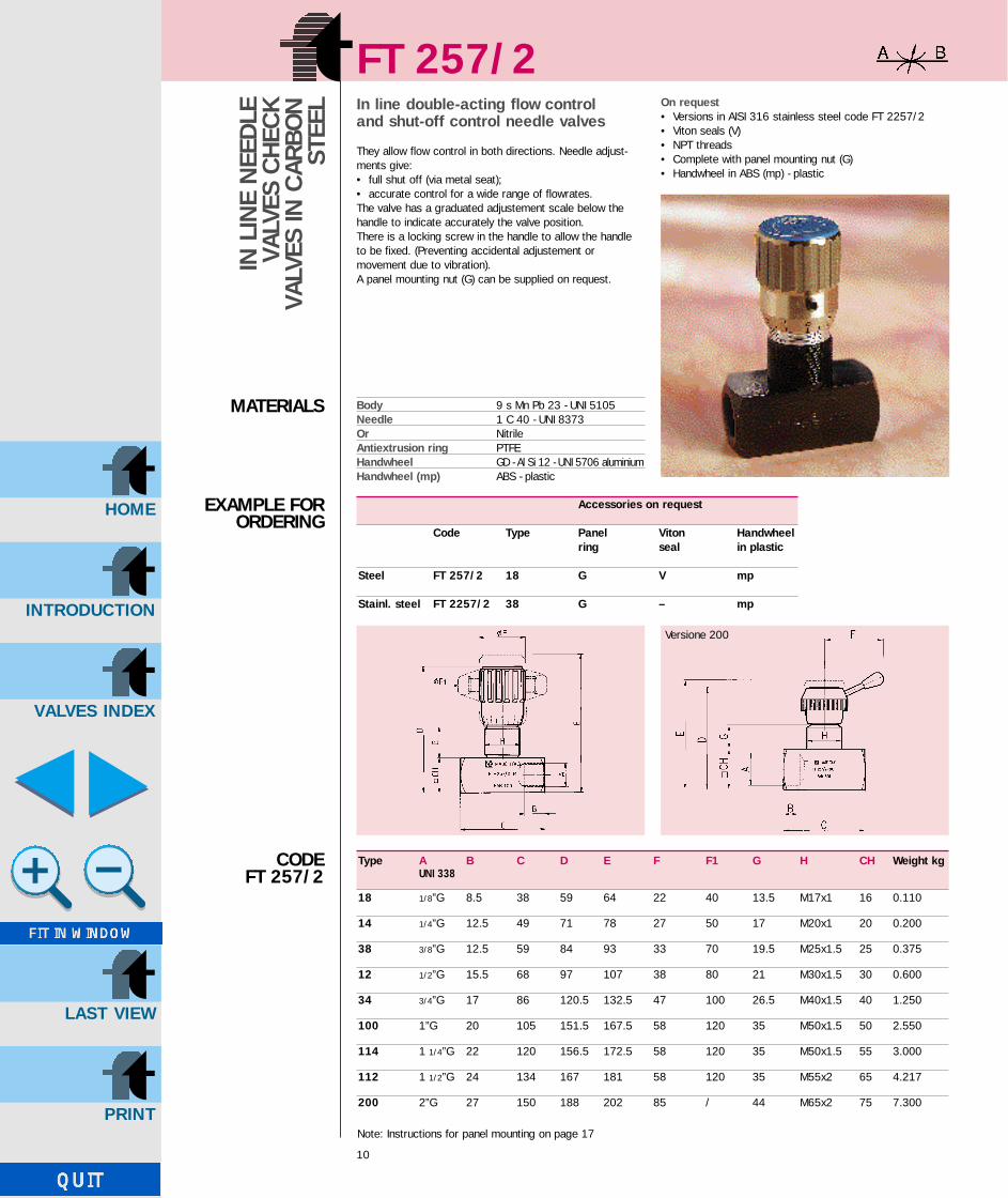
L In line double-acting flow control and shut-off control needle valves
They allow flow control in both directions. Needle adjust-ments give:• full shut off (via metal seat);• accurate control for a wide range of flowrates.The valve has a graduated adjustement scale below thehandle to indicate accurately the valve position.There is a locking screw in the handle to allow the handle to be fixed. (Preventing accidental adjustement or movement due to vibration).A panel mounting nut (G) can be supplied on request.
On request• Versions in AISI 316 stainless steel code FT 2257/2• Viton seals (V)• NPT threads• Complete with panel mounting nut (G)• Handwheel in ABS (mp) - plastic
CODE FT 257/2
Type A B C D E F F1 G H CH Weight kgUNI 338
18 1/8”G 8.5 38 59 64 22 40 13.5 M17x1 16 0.110
14 1/4”G 12.5 49 71 78 27 50 17 M20x1 20 0.200
38 3/8”G 12.5 59 84 93 33 70 19.5 M25x1.5 25 0.375
12 1/2”G 15.5 68 97 107 38 80 21 M30x1.5 30 0.600
34 3/4”G 17 86 120.5 132.5 47 100 26.5 M40x1.5 40 1.250
100 1”G 20 105 151.5 167.5 58 120 35 M50x1.5 50 2.550
114 1 1/4”G 22 120 156.5 172.5 58 120 35 M50x1.5 55 3.000
112 1 1/2”G 24 134 167 181 58 120 35 M55x2 65 4.217
200 2”G 27 150 188 202 85 / 44 M65x2 75 7.300
Body 9 s Mn Pb 23 - UNI 5105Needle 1 C 40 - UNI 8373Or NitrileAntiextrusion ring PTFEHandwheel GD - Al Si 12 - UNI 5706 aluminiumHandwheel (mp) ABS - plastic
MATERIALS
Accessories on request
Code Type Panel Viton Handwheelring seal in plastic
Steel FT 257/2 18 G V mp
Stainl. steel FT 2257/2 38 G – mp
EXAMPLE FOR ORDERING
Note: Instructions for panel mounting on page 17
Versione 200
GB-TognellaxCD 20/08/2001 11:55 Pagina 12

INTRODUCTION
HOME
VALVES INDEX
LAST VIEW
FT 258/2
11
IN L
INE
NEE
DLE
VA
LVES
CH
ECK
VALV
ES IN
CAR
BON
STEE
L
CODE FT 258/2
MATERIALS
EXAMPLEFORORDERING
90° angle double-acting shut-off control valves
They allow flow control in both directions. Needle adjust-ments give:• full shut off (via metal seat)• accurate control for a wide range of flowrates.The valve has a graduated adjustement scale below thehandle to indicate accurately the valve position.There is a locking screw in the handle to allow the handle to be fixed. (Preventing accidental adjustement or move-ment due to vibration).A panel mounting nut (G) can be supplied on request.
On request• Versions in AISI 316 stainless steel code FT 2258/2• Viton seals (V)• NPT threads• Complete with panel mounting nut (G)• Handwheel in ABS (mp) - plastic
Type A B C C1 D E F F1 G H CH Weight kgUNI 338
18 1/8”G 8.5 19 20 71 76 22 40 14.5 M17x1 16 0.108
14 1/4”G 13.5 25 27 86.5 93.5 27 50 17 M20x1 20 0.200
38 3/8”G 12.5 29.5 31.5 101.5 110.5 33 70 19.5 M25x1.5 25 0.360
12 1/2”G 15.5 35 37 117 127 38 80 21 M30x1.5 30 0.580
34 3/4”G 17 42 46 142.5 154.5 47 100 26.5 M40x1.5 40 1.265
100 1”G 20 53 56 182.8 198.8 58 120 35 M50x1.5 50 2.500
Body 9 s Mn Pb 23 - UNI 5105Needle 1 C 40 - UNI 8373Or NitrileAntiextrusion ring PTFEHandwheel GD - Al Si 12
UNI 5706 aluminiumHandwheel (mp) ABS - plastic
Accessories on request
Code Type Panel Viton Handwheelring seal in plastic
Steel FT 258/2 G V mp
Stainl. steel FT 2258/2 12 G – mp
Note: Instructions for panel mounting on page 17
GB-TognellaxCD 20/08/2001 11:55 Pagina 13

INTRODUCTION
HOME
VALVES INDEX
LAST VIEW
FT 257/2 - 258/2
12
Type Port section Working Min. burst. Working Filtration sq. cm pressure bar pressure bar temp. °C grade µm
18 0.12 400 1600 -20°/+100° 25
14 0.19 400 1600 -20°/+100° 25
38 0.39 400 1600 -20°/+100° 25
12 0.68 400 1600 -20°/+100° 25
34 1.13 400 1600 -20°/+100° 25
100 2.09 320 1300 -20°/+100° 25
114 2.09 320 1300 -20°/+100° 25
112 3.14 320 1300 -20°/+100° 25
200 4.91 320 1300 -20°/+100° 25
TECHNICALDATA
FLOWRATECURVES
FT 257/2-FT 258/2-18
FT 257/2-FT 258/2-38
FT 257/2-FT 258/2-14
GB-TognellaxCD 20/08/2001 11:55 Pagina 14

INTRODUCTION
HOME
VALVES INDEX
LAST VIEW
FT 257/2 - 258/2
13
FT 257/2-FT 258/2-12
FT 257/2-100
FT 257/2-114 FT 257/2-112
FT 257/2-200
FT 257/2-FT 258/2-34
GB-TognellaxCD 20/08/2001 11:55 Pagina 15

INTRODUCTION
HOME
VALVES INDEX
LAST VIEW
FT 257/5
14
IN L
INE
NEE
DLE
VA
LVES
CH
ECK
VALV
ES IN
CAR
BON
STEE
L
CODE FT 257/5
MATERIALS
EXAMPLEFOR
ORDERING
Single-acting control needle valves in line
Their function is to control and eventually shut-off the flowin one direction, allowing a free return flow in the oppositedirection.The check valve spring is housed in such a way that it doesnot close as a pack during opening of the scheck valve poppet.Needle adjustments give:• full shut off (via metal seat);• accurate control for a wide range of flowrates.The valve has a graduated adjustement scale below thehandle to indicate accurately the valve position.There is a locking screw in the handle to allow the handle tobe fixed. (Preventing accidental adjustement or movementdue to vibration).
A panel mounting nut (G) can be supplied on request.Opening pressure is 0.35 bar.
On request• Versions in AISI 316 stainless steel code FT 2257/5• Viton seals (V)• NPT threads• Complete with panel mounting nut (G)• Handwheel in ABS (mp) - plastic
Type A B C D E F F1 G H CH Weight kgUNI 338
18 1/8”G 8.5 50 59 64 22 40 13.5 M17x1 16 0.130
14 1/4”G 12.5 66 71 78 27 50 17 M20x1 20 0.250
38 3/8”G 12.5 79 84 93 33 70 19.5 M25x1.5 25 0.500
12 1/2”G 15.5 94.5 97 107 38 80 21 M30x1.5 30 0.750
34 3/4”G 17 115 120.5 132.5 47 100 26.5 M40x1.5 40 1.600
100 1”G 20 138.5 151.5 167.5 58 120 35 M50x1.5 50 3.050
114 1 1/4”G 22 157 156.5 172.5 58 120 35 M50x1.5 55 3.750
112 1 1/2”G 24 190 167 181 58 120 35 M55x2 65 5.760
200 2”G 27 228 188 202 85 – 44 M65x2 75 10.000
Body 9 s Mn Pb 23 - UNI 5105Needle 1 C 40 - UNI 8373Or NitrileAntiextrusion ring PTFECheck Valve 38 Ni Cr Mo 4 - UNI - EN 10083Spring C 72 UNI 3545Threaded end-plate 35 S Mn Pb 10 - UNI 5105Handwheel GD - Al Si 12 - UNI 5706 aluminiumHandwheel (mp) ABS - plastic
Note: Instructions for panel mounting on page 17
Accessories on request
Code Type Panel Viton Handwheel ring seal in plastic
Steel FT 257/5 18 G V mp
Stainl. steel FT 2257/5 34 G V mp
GB-TognellaxCD 1/10/2001 15:08 Pagina 16

FT 257/5
15
TECHNICALDATA
FLOWRATE CURVES
FT 257/5
FT 257/5-18 FT 257/5-14
Versione 200
Type Port section Working Min. Burst. Working Filtration gradesq. cm pressure bar pressure bar temperature °C µm
18 0.12 400 1600 -20°/+100° 25
14 0.19 400 1600 -20°/+100° 25
38 0.39 400 1600 -20°/+100° 25
12 0.68 400 1600 -20°/+100° 25
34 1.13 400 1600 -20°/+100° 25
100 2.09 320 1300 -20°/+100° 25
114 2.09 320 1300 -20°/+100° 25
112 3.14 320 1300 -20°/+100° 25
200 4.91 320 1300 -20°/+100° 25
INTRODUCTION
HOME
VALVES INDEX
LAST VIEW
GB-TognellaxCD 20/08/2001 11:55 Pagina 17

INTRODUCTION
HOME
VALVES INDEX
LAST VIEW
FT 257/5
16
FT 257/5-38
FT 257/5-12 FT 257/5-34
FT 257/5-100 FT 257/5-114
FT 257/5-112 FT 257/5-200
GB-TognellaxCD 20/08/2001 11:55 Pagina 18

INTRODUCTION
HOME
VALVES INDEX
LAST VIEW
SERIE FT 257 - FT 258
17
Seal and lock nut spare parts
Type 18 14 38 12 34 100 114 112 200
(7) OR 2018 2021 108 2043 115 123 123 128 3106
(6) Antiextrusion ring 2018 2021 108 2043 115 123 123 128 3106
(9) Lock nut KM KM 3 KM 4 KM 5 KM 6 KM 8 KM 10 KM 10 KM 11 KM 13(FT 202/3) (FT 202/4) (FT 202/5) (FT 202/6) (FT 202/8) (FT 202/10) (FT 202/10)
A max thickness 6 8 10 10 10 10 10 12 12
B bore for panel mount. 18 21 26 31 41 51 51 56 66
Montaggio a pannello
1° Allentare il grano di pressione (4)
2° Togliere il tappo (1)
3° Svitare la vite (2)
4° Estrarre con forza la manopola (3)
5° Introdurre la ghiera KM (9) indicata nella tabella (a richiesta viene fornita con la valvola)
DISASSEMBLYINSTRUCTIONS TO FIT PANELMOUNT NUT
1
2
3
4
5
67
8
9
A
B
GB-TognellaxCD 20/08/2001 11:55 Pagina 19

INTRODUCTION
HOME
VALVES INDEX
LAST VIEW
FT 257/6
18
IN L
INE
NEE
DLE
VA
LVES
CH
ECK
VALV
ES IN
CAR
BON
STEE
L
CODE FT 257/6
MATERIALS
EXAMPLEFOR
ORDERING
Check valve with machined cone poppet
The valve has a metal to metal seat incorporating a highquality machined cone/spool with hardened tip.They may be supplied with various springs (0.35 standard, optional 2-4-6-8-10 bar).
On request• Version AISI 316 stainless steel code FT 2257/6• NPT threads
Type A B C CH Working Weight kgUNI 338 pressure bar
18 1/8”G 8.5 46 17 400 0.075
14 1/4”G 12.5 63 22 400 0.165
38 3/8”G 12.5 69 27 400 0.260
12 1/2”G 15.5 80.5 32 400 0.415
34 3/4”G 17 99.5 36 400 0.605
100 1”G 20 117 46 320 1.170
114 11/4”G 22 134.5 55 320 1.850
112 1 1/2”G 24 159 65 320 3.130
200 2”G 27 198 75 320 4.900
Body 9 S Mn Pb 23 - UNI 5105Check valve 38 Ni Cr Mo 4
UNI - EN 10083Spring C 72 UNI 3545Threaded end-plate 35 S Mn Pb 10 - UNI 5105
Code Type Calibration
Steel FT 257/6 14 –
Stainl. steel FT 2257/6 12 –
Steel FT 257/6/8 34 8
GB-TognellaxCD 20/08/2001 11:55 Pagina 20
INTRODUCTION
HOME
VALVES INDEX
LAST VIEW
FT 257/6
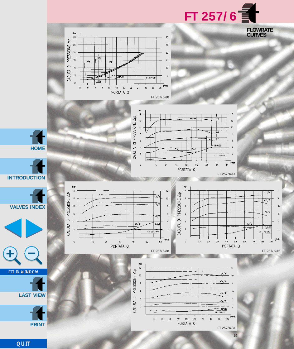
19
FLOWRATE CURVES
FT 257/6-18
FT 257/6-14
FT 257/6-12FT 257/6-38
FT 257/6-34
GB-TognellaxCD 20/08/2001 11:55 Pagina 21

INTRODUCTION
HOME
VALVES INDEX
LAST VIEW
FT 257/6
20
FT 257/6-112 FT 257/6-200
FT 257/6-114
FLOWRATE CURVES
FT 257/6-100
GB-TognellaxCD 20/08/2001 11:55 Pagina 22

INTRODUCTION
HOME
VALVES INDEX
LAST VIEW
Type A B C CH Working Weight kgUNI 338 pressure bar
18 1/8”G 8.5 41 16 350 0.054
14 1/4”G 12.5 54 19 350 0.089
38 3/8”G 13 65 24 350 0.175
12 1/2”G 16 77 30 350 0.310
34 3/4”G 20 88 36 350 0.450
100 1”G 23 108.5 46 320 0.965
FT 260/6
21
EXAMPLEFORORDERING
MATERIALS
Ball type check valves
These check valves have a guided ball giving a metal tometal seat.They may be supplied with two springs (0.35 standard and 4.5 bar).They are used for working pressures up to 350 bar.
On request• Version AISI 316 stainless steel code FT 2260/6
Body 9 S Mn Pb 23 - UNI 5105Spring AISI 302Ball UNI 100 C 6Ball guide Nylon 66 + carbon fibre
Code Type
Steel FT 260/6 14
Stainl. steel FT 2260/6 12
CODE FT 260/6
GB-TognellaxCD 20/08/2001 11:55 Pagina 23

INTRODUCTION
HOME
VALVES INDEX
LAST VIEW
FT 260/6
22
FT 260/6-100
FT 260/6-34FT 260/6-12
FT 260/6-38FT 260/6-14
FT 260/6-18
FLOWRATE CURVES
GB-TognellaxCD 20/08/2001 11:55 Pagina 24

INTRODUCTION
HOME
VALVES INDEX
LAST VIEW
23
CARTRIDGE MOUNTED SHUT-OFF AND CONTROL
NEEDLE VALVES
FT 247/2FT 267/2FT 267/5FT 267/6
GB-TognellaxCD 20/08/2001 11:55 Pagina 25

INTRODUCTION
HOME
VALVES INDEX
LAST VIEW
24
They are manufactured in the four versions:
FT 247/2 for fine control FT 267/2 double-acting control valvesFT 267/5 single-acting control valvesFT 267/6 check valves
Sealing between valves and connections surface is obtained either with the normal toroidal ‘O’ ring orwith a Bonded Dowty seal.On pages 32, 33, 34, 35 are indicated the machining schemes for the realtive embedding seat.The exclusive system designed for the realization of type FT 267/5, which includes the non-return devi-ce in the cartridge itself, avoids to the user costly machinings for the realization of specific seats suita-ble to receive separately the cut-off valve.The accurate surface finishe of the moving and sealing organs, the high quality standard and the efficient protective treatments bring about an almost unlimited service-life, even in the most severe working conditions.
Moreover they kept the essential prerogatives of series FT 257 i.e.:• semplicity to set-up and reset the flow values;• efficient metallic sealing;• absolute safety against needle withdrawal;• stability of positioning.
CAR
TRID
GE
MO
UNTE
D
SHUT
-OFF
AN
D
CO
NTR
OL
NEE
DLE
VA
LVES
FT 247/2 FT 267/2FT 267/5FT 267/6
GB-TognellaxCD 20/08/2001 11:55 Pagina 26

INTRODUCTION
HOME
VALVES INDEX
LAST VIEW
25
CAR
TRID
GE
MO
UNTE
D
SHUT
-OFF
AN
D
CO
NTR
OL
NEE
DLE
VA
LVES
CODE FT 247/2
MATERIALS
EXAMPLEFORORDERING
Fine control double-acting valves forcartridge mounting
This version is similar to the series FT 257, the followingcharacteristics are maintained:• metallic sealing;• safety against needle withdrawal.
On request• They are provided with seals in viton (V)
Kit of seals on the seat
Type (1) OR (2) BK
18 108 BK 18 (FT)
Kit of seals on the needle
Type OR BK
18 2018 2018
Body 95 Mn Pb 28 - UNI 5105Needle AISI 303Or NitrileAntiextrusion ring PTFEHandwheel GD - Al Si 12 - UNI 5706 aluminium
Accessories on request
Code Type Viton seal
FT 247/2 18 V
Type A nB C nD E F G Es. Weight kgUNI 4534
18 M15x1 12 20.5 22 34.5 55 8 22 0.069
FT 247/2
GB-TognellaxCD 20/08/2001 11:55 Pagina 27
INTRODUCTION
HOME
VALVES INDEX
LAST VIEW
26
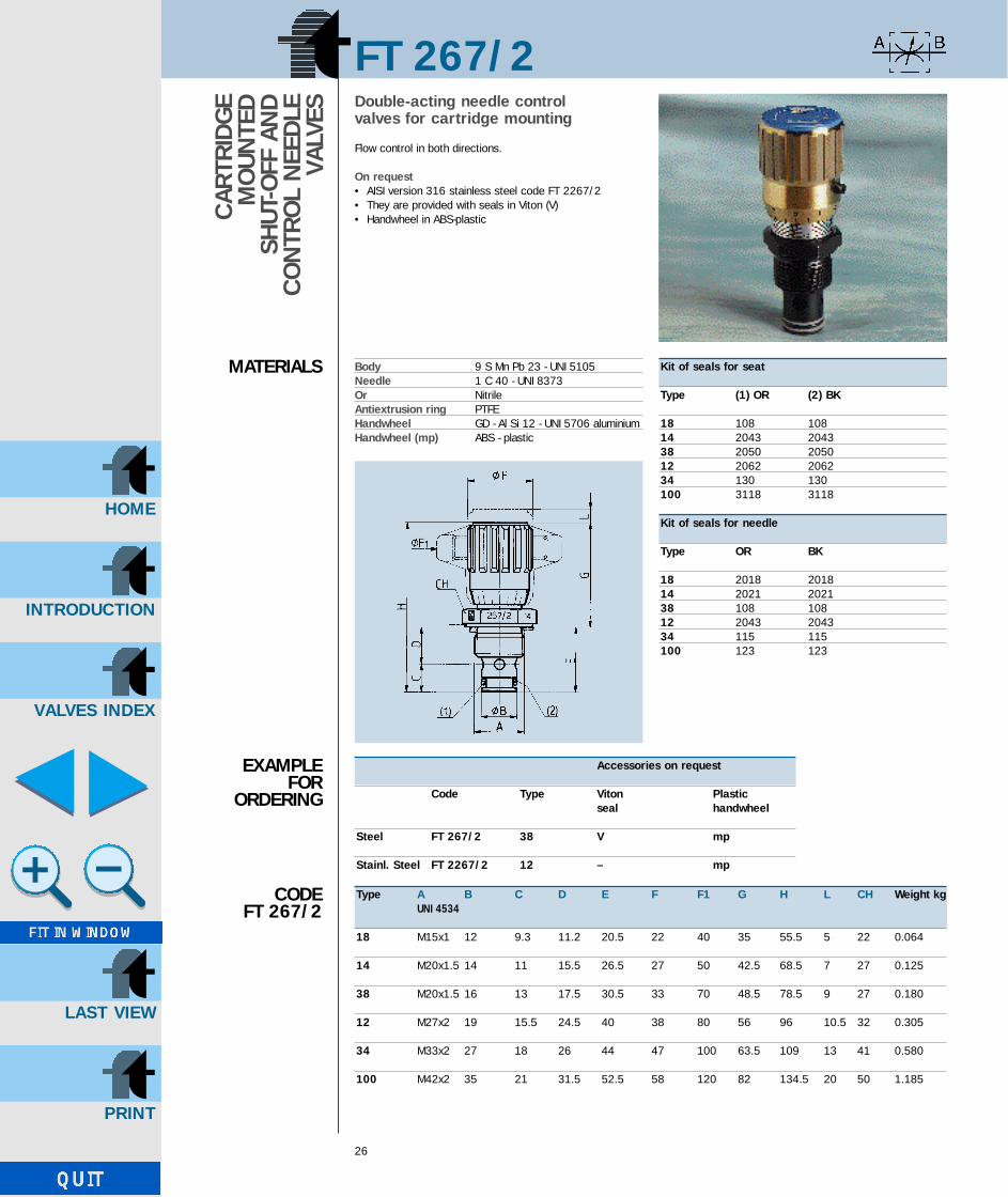
FT 267/2Double-acting needle control valves for cartridge mounting
Flow control in both directions.
On request• AISI version 316 stainless steel code FT 2267/2• They are provided with seals in Viton (V)• Handwheel in ABS-plasticC
ARTR
IDG
E M
OUN
TED
SH
UT-O
FF A
ND
C
ON
TRO
L N
EED
LEVA
LVES
CODE FT 267/2
MATERIALS
EXAMPLEFOR
ORDERING
Type A B C D E F F1 G H L CH Weight kgUNI 4534
18 M15x1 12 9.3 11.2 20.5 22 40 35 55.5 5 22 0.064
14 M20x1.5 14 11 15.5 26.5 27 50 42.5 68.5 7 27 0.125
38 M20x1.5 16 13 17.5 30.5 33 70 48.5 78.5 9 27 0.180
12 M27x2 19 15.5 24.5 40 38 80 56 96 10.5 32 0.305
34 M33x2 27 18 26 44 47 100 63.5 109 13 41 0.580
100 M42x2 35 21 31.5 52.5 58 120 82 134.5 20 50 1.185
Kit of seals for seat
Type (1) OR (2) BK
18 108 10814 2043 204338 2050 205012 2062 206234 130 130100 3118 3118
Kit of seals for needle
Type OR BK
18 2018 201814 2021 202138 108 10812 2043 204334 115 115100 123 123
Body 9 S Mn Pb 23 - UNI 5105Needle 1 C 40 - UNI 8373Or NitrileAntiextrusion ring PTFEHandwheel GD - Al Si 12 - UNI 5706 aluminiumHandwheel (mp) ABS - plastic
Accessories on request
Code Type Viton Plasticseal handwheel
Steel FT 267/2 38 V mp
Stainl. Steel FT 2267/2 12 – mp
GB-TognellaxCD 20/08/2001 11:55 Pagina 28

INTRODUCTION
HOME
VALVES INDEX
LAST VIEW
FT 267/5
27
CAR
TRID
GE
MO
UNTE
D S
HUT
-OFF
AND
CO
NTR
OL
NEE
DLE
VAL
VES
CODE FT 267/5
MATERIALS
EXAMPLEFORORDERING
Single-acting needle control valves forcartridge mounting
They control and eventually shut-off the flow in one direction, allowing a free return in the opposed direction.Non-return valve set at 0.35 bar.
On request• AISI version 316 stainless steel code FT 2267/5• They are provided with Viton seals (V)• Handwheel in ABS plastic
Type A B E F F1 G H L CH Weight kgUNI 4534
14 M20x1.5 16 30.5 27 50 43 73.5 4 27 0.130
38 M27x2 19 40 33 49 70 89 6 32 0.250
12 M33x2 27 44.5 38 60 80 104.5 7 41 0.340
34 M42x2 35 52.5 47 70 100 112.5 8 50 0.620
100 M52x2 45 64.5 58 120 85 149.5 12 60 1.632
Kit of seals for seat
Type (1) OR (2) BK speciale14 2050 BK 14 (FT)38 2062 BK 38 (FT)12 130 BK 12 (FT)34 3118 BK 34 (FT)100 3156 3156
Kit of seals for needle
Type OR Anello antiestrusione
14 2012 200-80138 2018 201812 106 10634 108 108100 112 112
Body 9 S Mn Pb 23 - UNI 5105Needle 38 Ni Cr Mo 4 - UNI - EN 10083Or NitrileAntiextrusion ring PTFECheck valve 38 Ni Cr Mo 4 - UNI - EN 10083Spring C 72 - UNI 3545Handwheel GD - Al Si 12 - UNI 5706 aluminiumHandwheel (mp) ABS - plastic
Accessories on request
Code Type Viton Handwheelseal in plastic
Steel FT 267/5 34 V mp
Stainl. Steel FT 2267/5 12 – mp
GB-TognellaxCD 20/08/2001 11:55 Pagina 29
INTRODUCTION
HOME
VALVES INDEX
LAST VIEW
FT 267/6
28
CAR
TRID
GE
MO
UNTE
D S
HUT
-OFF
AND
CO
NTR
OL
NEE
DLE
VAL
VES
CODE FT 267/6
MATERIALS
EXAMPLEFOR
ORDERING
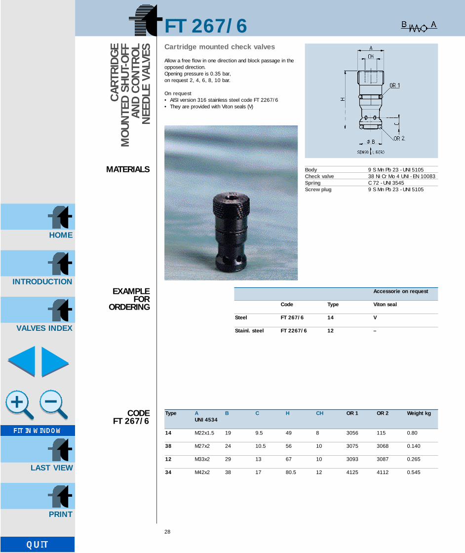
Cartridge mounted check valves
Allow a free flow in one direction and block passage in theopposed direction.Opening pressure is 0.35 bar,on request 2, 4, 6, 8, 10 bar.
On request• AISI version 316 stainless steel code FT 2267/6• They are provided with Viton seals (V)
Type A B C H CH OR 1 OR 2 Weight kgUNI 4534
14 M22x1.5 19 9.5 49 8 3056 115 0.80
38 M27x2 24 10.5 56 10 3075 3068 0.140
12 M33x2 29 13 67 10 3093 3087 0.265
34 M42x2 38 17 80.5 12 4125 4112 0.545
Body 9 S Mn Pb 23 - UNI 5105Check valve 38 Ni Cr Mo 4 UNI - EN 10083Spring C 72 - UNI 3545Screw plug 9 S Mn Pb 23 - UNI 5105
Accessorie on request
Code Type Viton seal
Steel FT 267/6 14 V
Stainl. steel FT 2267/6 12 –
GB-TognellaxCD 1/10/2001 15:19 Pagina 30

INTRODUCTION
HOME
VALVES INDEX
LAST VIEW
FT 247/2
29
TECHNICALDATA
Type Max. working Min. burst. Port Working Filtrationpressure pressure section temp. grade
bar bar sq. cm °C µm
18 320 1300 0.0314 -20°/+100° 25
FLOWRATE CURVES
FT 247/2-18
GB-TognellaxCD 20/08/2001 11:55 Pagina 31

INTRODUCTION
HOME
VALVES INDEX
LAST VIEW
30
TECHNICALDATA
FLOWRATE CURVES
FT 267/2-18
FT 267/2-38
FT 267/2-14
FT 267/2-12
FT 267/2-34 FT 267/2-100
FT 267/2Type Port section Working Min. burst. Working Filtration grade
sq. cm pressure bar pressure bar temperature °C µm
18 0.12 320 1300 -20°/+100° 25
14 0.19 320 1300 -20°/+100° 25
38 0.39 320 1300 -20°/+100° 25
12 0.68 320 1300 -20°/+100° 25
34 1.13 320 1300 -20°/+100° 25
100 2.09 320 1300 -20°/+100° 25
GB-TognellaxCD 20/08/2001 11:55 Pagina 32

INTRODUCTION
HOME
VALVES INDEX
LAST VIEW
31
TECHNICALDATA
FLOWRATE CURVES
FT 267/5 FT 267/5-14
FT 267/5-38 FT 267/5-12
FT 267/5-34 FT 267/5-100
FT 267/5Type Port section Working Min. burst. Working Filtration grade
sq. cm pressure bar pressure bar temperature °C µm
14 0.07 320 1300 -20°/+100° 25
38 0.15 320 1300 -20°/+100° 25
12 0.37 320 1300 -20°/+100° 25
34 1.56 320 1300 -20°/+100° 25
100 3.80 320 1300 -20°/+100° 25
GB-TognellaxCD 20/08/2001 11:55 Pagina 33

INTRODUCTION
HOME
VALVES INDEX
LAST VIEW
32
Type Working Min. burst. Working Filtrationpressure bar pressure bar temperature °C grade µm
14 320 1300 -20°/+100° 25
38 320 1300 -20°/+100° 25
12 320 1300 -20°/+100° 25
34 320 1300 -20°/+100° 25
TECHNICALDATA
FLOWRATECURVES
FT 267/6
Type A B C D E F G H K LUNI 4534 min. max.
14 M22x1.5 20.5 16.5 13.5 19 45.5 10 52 8 33.5 36
38 M27x2 25 18 16 24 52.5 15 59 10 36.5 40
12 M33x2 31 21 17 29 63.5 20 71 12 45 49
34 M42x2 40 25 20 38 76 26 85.5 15 52 59
SCH
EMES
FO
R C
AVIT
Y M
ACH
ININ
GFO
R VA
LVE
DIMENSIONSTABLE FOR
CAVITY
FT 267/6
GB-TognellaxCD 20/08/2001 11:55 Pagina 34
INTRODUCTION
HOME
VALVES INDEX
LAST VIEW
FT 247/2-FT 267/2-FT 267/5
33
SCH
EMES
FO
R C
AVIT
Y M
ACH
ININ
G F
OR
CAR
TRID
GE
MO
UNTE
D V
ALVE
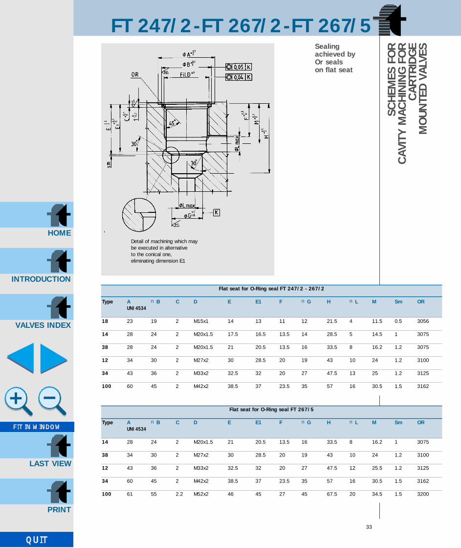
SSealing achieved by Or seals on flat seat
Detail of machining which maybe executed in alternative to the conical one, eliminating dimension E1
Flat seat for O-Ring seal FT 247/2 - 267/2
Type A nB C D E E1 F nG H nL M Sm ORUNI 4534
18 23 19 2 M15x1 14 13 11 12 21.5 4 11.5 0.5 3056
14 28 24 2 M20x1.5 17.5 16.5 13.5 14 28.5 5 14.5 1 3075
38 28 24 2 M20x1.5 21 20.5 13.5 16 33.5 8 16.2 1.2 3075
12 34 30 2 M27x2 30 28.5 20 19 43 10 24 1.2 3100
34 43 36 2 M33x2 32.5 32 20 27 47.5 13 25 1.2 3125
100 60 45 2 M42x2 38.5 37 23.5 35 57 16 30.5 1.5 3162
Flat seat for O-Ring seal FT 267/5
Type A nB C D E E1 F nG H nL M Sm ORUNI 4534
14 28 24 2 M20x1.5 21 20.5 13.5 16 33.5 8 16.2 1 3075
38 34 30 2 M27x2 30 28.5 20 19 43 10 24 1.2 3100
12 43 36 2 M33x2 32.5 32 20 27 47.5 12 25.5 1.2 3125
34 60 45 2 M42x2 38.5 37 23.5 35 57 16 30.5 1.5 3162
100 61 55 2.2 M52x2 46 45 27 45 67.5 20 34.5 1.5 3200
GB-TognellaxCD 20/08/2001 11:55 Pagina 35

INTRODUCTION
HOME
VALVES INDEX
LAST VIEW
FT 247/2-FT 267/2-FT 267/5
34
Sealing achievedby Bonded seal
Detail of machining which may be executed in alternative to the conical one,eliminating dimension E1
SCH
EMES
FO
R C
AVIT
Y M
ACH
ININ
G
FOR
CAR
TRID
GE
MO
UNTE
D V
ALVE
S
Cavity Bonded seal – FT 267/5
Type A C D E E1 F nG H nL M Sm Bonded sealUNI 4534
14 27 1 M20x1.5 20 19.5 12 16 32 8 15.2 1 400-513
38 33 1.3 M27x2 28 26.5 18 19 41 10 22 1.2 400-520
12 40 1.3 M33x2 30.5 30 18 27 45.5 12 23 1.2 400-515
34 50 1.3 M42x2 36.5 35 21.5 35 55 16 28.5 1.5 400-516
Cavity Bonded seal – FT 247/2 - 267/2
Type A C D E E1 F nG H nL M Sm Bonded sealUNI 4534
18 23 1 M15x1 13 12 9 12 20 4 10.3 0.5 400-512
14 27 1 M20x1.5 16.5 15.5 12 14 27 5 13.3 1 400-513
38 27 1 M20x1.5 20 19.5 12 16 32 8 15.2 1.2 400-513
12 33 1.3 M27x2 28 26.5 18 19 41 10 22 1.2 400-520
34 40 1.3 M33x2 30.5 30 18 27 45.5 13 23 1.2 400-515
100 50 1.3 M42x2 36.5 35 21.5 35 55 16 28.5 1.5 400-516
GB-TognellaxCD 20/08/2001 11:55 Pagina 36

INTRODUCTION
HOME
VALVES INDEX
LAST VIEW
FT 247/2-FT 267/2-FT 267/5
SCH
EMES
FO
R C
AVIT
Y M
ACH
ININ
G F
OR
CAR
TRID
GE
MO
UNTE
D V
ALVE
SSealing achievedby Or seals onconical cavity
Conical cavity for O-ring – FT 247/2 - FT 267/2
Type A nB C D E F nG H ØL M nN Sm ORUNI 4534
18 16.5 M15x1 0.25 14 13 11 12 21.5 4 11.5 23 0.5 2050
14 22.3 M20x1.5 0.25 17.5 16.5 13.5 14 28.5 5 28 14.5 1 3068
38 22.3 M20x1.5 0.25 21 20.5 13.5 16 33.5 8 28 16.2 1.2 3068
12 29.1 M27x2 0.3 30 28.5 20 19 43 10 24 34 1.2 132
34 36 M33x2 0.3 32.5 32 20 27 47.5 13 25 43 1.2 4112
100 45 M42x2 0.3 38.5 37 23.5 35 57 16 30.5 60 1.5 4150
Conical cavity for O-ring – FT 267/5
Type A nB C D E F nG H nL M nN Sm ORUNI 4534
14 22.3 M20x1.5 0.25 21 20.5 13.5 16 33.5 8 28 16.2 1.2 3068
38 29.1 M27x2 0.3 30 28.5 20 19 43 10 24 34 1.2 132
12 36 M33x2 0.3 32.5 32 20 27 47.5 13 25 43 1.2 4112
34 45 M42x2 0.3 38.5 37 23.5 35 57 16 30.5 60 1.5 4150
100 55 M52x2 0.3 46 45 27 45 67.5 20 34.5 61 1.5 4187
GB-TognellaxCD 20/08/2001 11:55 Pagina 37

INTRODUCTION
HOME
VALVES INDEX
LAST VIEW
GB-TognellaxCD 20/08/2001 11:55 Pagina 38

INTRODUCTION
HOME
VALVES INDEX
LAST VIEW
37
PRESSURE COMPENSATEDFLOW CONTROL VALVES
FT 277/2FT 277/5FT 287/2FT 297/2FT 270/2FT 270/5
GB-TognellaxCD 20/08/2001 11:55 Pagina 39

INTRODUCTION
HOME
VALVES INDEX
LAST VIEW
FT 277/2
38
Two inlet flow control valves, pressurecompensated and including high capacity single acting valve to allowthe free flow in one direction.
They include two necks in series:• the first one with port section definable by an
external control;• the second one with automatically variable section
in relation with counterpressure variations on use.The choice of the adjustable neck situated upstream is thatwhich best ensures the precision of the valve towards varia-tions of the fluid temperature.Regarding the structure of the valve, the following pointsmust be underlined• the rigorous symmetry of the internal components
such as to impede umforeseen perturbations of the static and dynamic balances;
• the optimization of the arrangement of internal spring controlling the intervention of the automatic throttling, with variable preload with throttling fixed setting, useful
to improve the behaviour at medium-high flowrates;• the geometry of the passage accross which the flow is
automatically throttled, designed to minimize the effectof the flow hydromechanic forces on the total balan-ce of the moving element;• the accuracy of the machinings which enabled to cancel
any hysteresis effect of mechanical origin;• the original aesthetic feature, underlined by the particular
form of control handwheel;• the easiness to reset the flow value thanks to
reference pointers.Moreover we believe important to underline the choice ofconstructive solution fitting to the concept of “double valen-ce”, according to which the central body, configurated as athreaded cartridge and insertable in the two differentbodies at the base or directly in standard modular units,brings about the three marketed versions:• FT 277/2 two-way• FT 277/5 two-way with single-acting valve;• FT 287/2 two-way with threaded cartridge.The solution enables the user to request the single modularcomponents to be assembled according to the application.
On request• Complete with rings (G)• Seals in Viton (V)
Type A B C D E F G H L CH Weight kgUNI 338
14 1/4”G 12.5 81 104.5 28 33 17 M30x1.5 4.5 40 1.000
38 3/8”G 12.5 100 127 32 38 27 M35x1.5 6 45 1.600
12 1/2”G 15.5 119 147.5 38 47 28.5 M40x1.5 6.5 55 2.800
34 3/4”G 17 142 180 45 58 35 M50x1.5 7.5 65 4.750
Base 9 S Mn Pb 23 - UNI 5105Cartridge body 35 S Mn Pb 10 - UNI 5105Compensation unit 38 Ni Cr Mo 4 - UNI - EN 10083Or NitrileAntiextrusion ring PTFEHandweel GD - Al Si 12
UNI 5706 aluminium
PRES
SURE
C
OM
PEN
SATE
D
FLO
W C
ON
TRO
L VA
LVES
CODE FT 277/2
MATERIALS
EXAMPLE FORORDERING
Note: Instructions for panel mounting on page 46
Accessories on request
Code Type Panel ring Viton seal
FT 277/2 34 G V
GB-TognellaxCD 20/08/2001 11:55 Pagina 40

INTRODUCTION
HOME
VALVES INDEX
LAST VIEW
FT 277/2
39
Type Max. working Min. Working Filtration gradepressure working ∆p temperature µm absolute
bar bar °C
14 320 7.5 -20°/+70° 25
38 320 10 -20°/+70° 25
12 320 12 -20°/+70° 25
34 320 15 -20°/+70° 25
TECHNICALDATA
FLOWRATE CURVES
FT 277 FT 277-14
FT 277-12 FT 277-38
FT 277-34
GB-TognellaxCD 20/08/2001 11:55 Pagina 41
INTRODUCTION
HOME
VALVES INDEX
LAST VIEW
FT 277/5
40
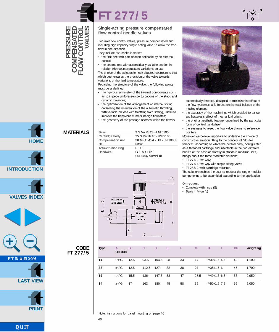
Single-acting pressure compensatedflow control needle valves
Two inlet flow control valves, pressure compensated andincluding high capacity single acting valve to allow the freeflow in one direction.They include two necks in series:• the first one with port section definable by an external
control;• the second one with automatically variable section in
relation with counterpressure variations on use.The choice of the adjustable neck situated upstream is thatwhich best ensures the precision of the valve towards variations of the fluid temperature.Regarding the structure of the valve, the following pointsmust be underlined• the rigorous symmetry of the internal components such
as to impede umforeseen perturbations of the static and dynamic balances;
• the optimization of the arrangement of internal spring controlling the intervention of the automatic throttling, with variable preload with throttling fixed setting, useful to improve the behaviour at medium-high flowrates;
• the geometry of the passage accross which the flow is
automatically throttled, designed to minimize the effect of the flow hydromechanic forces on the total balance of themoving element;
• the accuracy of the machinings which enabled to cancel any hysteresis effect of mechanical origin;
• the original aesthetic feature, underlined by the particularform of control handwheel;
• the easiness to reset the flow value thanks to reference pointers.
Moreover we believe important to underline the choice ofconstructive solution fitting to the concept of “double valence”, according to which the central body, configuratedas a threaded cartridge and insertable in the two differentbodies at the base or directly in standard modular units,brings about the three marketed versions:• FT 277/2 two-way;• FT 277/5 two-way with single-acting valve;• FT 287/2 with cartridge mounted.The solution enables the user to request the single modularcomponents to be assembled according to the application.
On request• Complete with rings (G)• Seals in Viton (V)
Type A B C D E F G H L CH Weight kgUNI 338
14 1/4”G 12.5 93.5 104.5 28 33 17 M30x1.5 4.5 40 1.100
38 3/8”G 12.5 112.5 127 32 38 27 M35x1.5 6 45 1.700
12 1/2”G 15.5 136 147.5 38 47 28.5 M40x1.5 6.5 55 2.950
34 3/4”G 17 163 180 45 58 35 M50x1.5 7.5 65 5.050
Base 9 S Mn Pb 23 - UNI 5105Cartridge body 35 S Mn Pb 10 - UNI 5105Compensation unit 38 Ni Cr Mo 4 - UNI - EN 10083Or NitrileAntiextrusion ring PTFEHandweel GD - Al Si 12
UNI 5706 aluminium
PRES
SURE
C
OM
PEN
SATE
D
FLO
W C
ON
TRO
L VA
LVES
CODE FT 277/5
MATERIALS
Note: Instructions for panel mounting on page 46
GB-TognellaxCD 20/08/2001 11:55 Pagina 42

INTRODUCTION
HOME
VALVES INDEX
LAST VIEW
FT 277/5
41
EXAMPLEFORORDERING
Type Max. working Min.working Working Filtration gradepressure bar ∆p bar temperature °C µm absolute
14 320 7.5 -20°/+70° 25
38 320 10 -20°/+70° 25
12 320 12 -20°/+70° 25
34 320 15 -20°/+70° 25
TECHNICALDATA
FLOWRATE CURVES
FT 277
FT 277-14 FT 277-12
FT 277-38 FT 277-34
FT 277/5
Accessories on request
Code Type Panel ring Viton seal
FT 277/5 12 G V
GB-TognellaxCD 20/08/2001 11:56 Pagina 43

INTRODUCTION
HOME
VALVES INDEX
LAST VIEW
FT 287/2
42
PRES
SURE
C
OM
PEN
SATE
D
FLO
W C
ON
TRO
L VA
LVES
CODE FT 287/2
MATERIALS
EXAMPLEFOR
ORDERING
Cartridge mounted pressure compensated flow control valves
They are essentially composed of the central body of val-ves series FT 277/2 which may be screwed in units presetby the user. The construction and functional characteristicsreflect exactly those described for the two inlet valves. It is recommended to keep them in their protective wrap-ping until the mounting, in order to avoid possible draw-backs caused by eventual entry of particles into the delica-te and essential parts for a good working.On page 46 is proposed a machining scheme for theembedding seat, which has to be observed to ensure thenecessary accuracy of the valve. The constructive systemallows the user, already provided with those versions, eitherto request the two inlet base bodies only, so as to allow
their quick transformation, or to store the single standardcomponents to assemble in the various types according tothe need.
On request• Seals in Viton (V)
Type A B E G F H L CH OR 1 Weight kgUNI 4534
14 M33x1.5 24 31 64.5 33 95.5 4.5 32 2081 0.350
38 M39x1.5 30 34.5 82 38 116.5 6 38 2106 0.580
12 M48x2 35 42 92.5 47 134.5 6.5 45 3118 0.960
34 M55x2 40 49 115 58 164 7.5 55 3137 1.700
Cartridge body 9 S Mn Pb 23 - UNI 5105Compensation unit 38 Ni Cr Mo 4 - UNI - EN 10083Or NitrileAntiextrusion ring PTFEHandwheel GD - Al Si 12
UNI 5706 aluminium
Note: Instructions for panel mounting on page 46
Accessori a richiesta
Code Type Viton seal
FT 287/2 38 V
GB-TognellaxCD 20/08/2001 11:56 Pagina 44

INTRODUCTION
HOME
VALVES INDEX
LAST VIEW
FT 287/2Type Max. working Min. Working Filtration grade
pressure working ∆p temperature µm absolutebar bar °C
14 320 7.5 -20°/+70° 25
38 320 10 -20°/+70° 25
12 320 12 -20°/+70° 25
34 320 15 -20°/+70° 25
TECHNICALDATA
FLOWRATECURVES
FT 287 FT 287-14
FT 287-12 FT 287-38
GB-TognellaxCD 20/08/2001 11:56 Pagina 45

INTRODUCTION
HOME
VALVES INDEX
LAST VIEW
FT 297/2
44
Fine control cartridge mounted pressure compensated flow control valves
Pressure compensated flowrate regulators, to insert in cur-rent model modular units.They are essentially composed of the central body of valvesseries FT 287/2 which may be screwed in units preset bythe user. The construction and functionally characteristicsreflect exactly those described for the two inlet valves.It is recommended to keep them in their protective wrap-ping until the mounting, in order to avoid possible draw-backs caused by eventual entry of particles into the delica-te and essential parts for a good working.On page 46 is proposed a machining scheme for theembedding seat, which has to be observed to ensure thenecessary accuracy of the valve.
On request• Seals in Viton (V)
Type A B E G F H L CH OR 1 Weight kgUNI 4534
14 M33x1.5 24 31 64.5 33 95.5 4.5 32 2081 0.350
Cartridge body 9 S Mn Pb 23 - UNI 5105Compensation unit 38 Ni Cr Mo 4 - UNI - EN 10083Or NitrileAntiextrusion ring PTFEHandwheel GD - Al Si 12 - UNI 5706 aluminium
PRES
SURE
C
OM
PEN
SATE
D
FLO
W C
ON
TRO
L VA
LVES
CODE FT 297/2
MATERIALS
EXAMPLEFOR
ORDERING Accessories on request
Code Type Viton seal
FT 297/2 14 V
Note: Instructions for panel mounting on page 46
GB-TognellaxCD 20/08/2001 11:56 Pagina 46

INTRODUCTION
HOME
VALVES INDEX
LAST VIEW
FT 297/2
475
Type Max. working Min. Working Filtration gradepressure working ∆p temperature µm absolute
bar bar °C
14 320 7.5 -20°/+70° 25
TECHNICALDATA
FLOWRATECURVES
FT 297/2-14
FT 297/2
GB-TognellaxCD 20/08/2001 11:56 Pagina 47

INTRODUCTION
HOME
VALVES INDEX
LAST VIEW
SERIE FT 277 - FT 287 - FT 297
46
Panel mounting FT 277/2 - FT 277/5
1° Unscrew handle lock screw - item (4)
2° Remove cover plate - item (1)
3° Remove screw - item (2)
4° Pull off handle - item (3)
5° Insert ring KM - item (9) - indicated in table (on request it is supplied with the valve)
DISASSEMBLYINSTRUCTIONSTO FIT PANELMOUNT NUT
FT 277/2 - FT 277/5 FT 287/2 - FT 297/2 - Machining schemes for seats
Type A B C D E F G H L M OR SmUNI 4535 (7)
14 39 35 5.2 M33x1.5 24 18 24 35.2 6.5 20 3118 0.8
38 44 40.5 5.2 M39x1.5 27.5 19 30 40 9 22.5 3143 0.8
12 53 49 6.5 M48x2 33.5 23.5 35 49 11 27.5 3175 0.8
34 63 58 7 M55x2 40 27 40 57 13.5 155 32.5 1
Ring KM for panel mounting
Type 14 38 12 34
Ring KM KM 6 KM 7 KM 8 KM 10
Code FT FT 202/6 FT 202/7 FT 202/8 FT 202/10
1
2
3
4
567
8
9
W
nY
Type 14 38 12 34
Thickness W max 10 10 10 10
Bore for panel mount. n Y 31 36 41 51
GB-TognellaxCD 20/08/2001 11:56 Pagina 48

INTRODUCTION
HOME
VALVES INDEX
LAST VIEW
FT 270/2
47
PRES
SURE
C
OM
PEN
SATE
D F
LOW
CO
NTR
OL
VALV
ESCODE FT 270/2
MATERIALS
EXAMPLEFORORDERING
Pressure compensated flow controlneedle valves
The accuracy of the working of the internal componentsensures a very low hysterisis.The careful controls performed on all the products guaran-tee that the valves function well even in the most difficultworking conditions.
On request• Complete with mounting nut (G)• Viton seals (V)
Type A B C D E F G H CH Weight kgUNI 338
14 1/4” G 12.5 94 81.5 88.5 27 15 M20x1 30 0.580
38 3/8” G 13 110.5 94.5 103 33 17 M25x1.5 35 0.940
12 1/2” G 15.5 137 112 122 38 18 M30x1.5 45 1.830
34 3/4” G 17 163 138 150 47 24 M40x1.5 55 3.350
100 1” G 21 214 175 192 58 32 M50x1.5 70 7.000
Accessories on request
Code Type Panel ring Viton seal
FT 270/2 14 G V
Body 9 S Mn Pb 28 - UNI 5105Compensation unit 38 Ni Cr Mo 4 - UNI - EN 10083Or NitrileAntiextrusion ring PTFEHandwheel GD Al Si 12 - UNI 5706 aluminium
GB-TognellaxCD 20/08/2001 11:56 Pagina 49

INTRODUCTION
HOME
VALVES INDEX
LAST VIEW
48
FT 270/5Single-acting pressure compensatedflow control needle valves
Inside the base there are wide transverse sections whichaprreaciably reduce the loss of pressure.The accuracy of the working of the internal componentsensures a very low hysterisis.The careful controls performed on all the products guarantee that the valves function well even in the most difficult working conditions.
On request• Complete with panel mounting nut • Viton seals (V)
PRES
SURE
C
OM
PEN
SATE
D
FLO
W C
ON
TRO
L VA
LVES
CODE FT 270/5
MATERIALS
EXAMPLEFOR
ORDERING
Type A B C D E F G H CH Weight kgUNI 338
14 1/4” G 12.5 94 81.5 88.5 27 15 M20x1 30 0.580
38 3/8” G 13 110.5 94.5 103 33 17 M25x1 35 0.940
12 1/2” G 15.5 137 112 122 38 18 M30x1.5 45 1.830
34 3/4” G 17 163 138 150 47 24 M40x1.5 55 3.350
100 1” G 21 214 175 192 58 32 M50x1.5 70 7.000
Body 9 S Mn Pb 28 - UNI 5105Compensation unit 38 Ni Cr Mo 4 - UNI - EN 10083Or NitrileAntiextrusion ring PTFEHandwheel GD Al Si 12 - UNI 5706 aluminium
Accessories on request
Code Type Panel ring Viton seal
FT 270/5 14 G V
GB-TognellaxCD 20/08/2001 11:56 Pagina 50

INTRODUCTION
HOME
VALVES INDEX
LAST VIEW
FT 270/2 - FT 270/5
49
TECHNICALDATA
FLOWRATECURVES
FT 270/2-270/5
FT 270/5
FT 270/2-270/5-14
Type Working Minimum Working Filtration gradepressure working ∆p temperature µm absolute
bar bar °C
14 210 5 -20°/+70° 25
38 210 7 -20°/+70° 25
12 210 10 -20°/+70° 25
34 210 10 -20°/+70° 25
100 210 16 -20°/+70° 25
GB-TognellaxCD 20/08/2001 11:56 Pagina 51

INTRODUCTION
HOME
VALVES INDEX
LAST VIEW
FT 270/2 - FT 270/5
50
FT 270/2-270/5-38
FT 270/2-270/5-12
FT 270/2-270/5-34
FT 270/2-100-270/5-100
FLOWRATECURVES
GB-TognellaxCD 20/08/2001 11:56 Pagina 52

INTRODUCTION
HOME
VALVES INDEX
LAST VIEW
51
FLOW CONTROL NEEDLE VALVES MANIFOLD MOUNTED
FT 280/2FT 280/5FT 280/6FT 281/2FT 281/5FT 288/2FT 288/5FT 289/2FT 289/5
GB-TognellaxCD 20/08/2001 11:56 Pagina 53

INTRODUCTION
HOME
VALVES INDEX
LAST VIEW
GB-TognellaxCD 20/08/2001 11:56 Pagina 54

INTRODUCTION
HOME
VALVES INDEX
LAST VIEW
FT 280/2
53
FLO
W C
ON
TRO
LN
EED
LE V
ALVE
SM
ANFO
LD
MO
UNTE
D
MATERIALS
FT 280/2 (type 03, 60, 18, 14, 38, 12)
Flow control needle valves
They allow for flow control in both directions.Needle adjustement to give:• full shut off (via metal seal);• accurate control for a wide range of flowrates.The valve has a graduated adjustement scale below thehandle to indicate accurately the valve position.There i a locking screw in the handle to allow the handle tobe fixed (preventing accidental adjustement or movementdue to vibration).They are provided with panel mounting connections mod.CETOP 03 or interchangeable with the broadly used valves.Max. working pressure is 250 bar.
Terminal strip body Steel 9 S Mn Pb 28UNI 5105
Cartridge body Steel 9 S Mn Pb 28UNI 5105
Needle Steel 1 C 40 - UNI 8373Handwheel GD Al Si 12
UNI 5706 aluminiumNipple Nylon 6OR NitrileAntiextrusion rings PTFEAll components are surface treated and protected
Type A B C D E nF G H L M N nP nQ OR Screws Weight kg
18 32 42 35 66.8 71.8 22 8 19 28.5 1.5 16 4 9.5 2025 M6x40 0.350
14 38 50 50 78.3 85.3 27 7.5 35 33.5 5 25.5 6 12.7 2037 M6x45 0.730
38 44 55 55 90.5 99.5 33 12 33.5 38 3.5 25.5 8 15.7 2050 M6x50 1.040
12 55 60 70 109.1 119.6 38 18 38 44.5 4 30 11 19.7 119 M6x60 1.810
EXAMPLEFORORDERING
Code Type
FT 280/2 18
FT 280/2 38
CODEFT 280/2
GB-TognellaxCD 20/08/2001 11:56 Pagina 55

INTRODUCTION
HOME
VALVES INDEX
LAST VIEW
Code Type
FT 280/2 03
FT 280/2 60
FT 280/2
54
Type A B C D E nF G H L M N P nQ nR S T OR Screws Weight kg
03 38 45 52 78.3 85.3 27 5.75 40.5 31.75 31 12.7 30.2 6 12 15.5 0.75 108 M5x40 0.700
EXAMPLEFOR
ORDERING
CODEFT 280/2
Type A B C D E nF G H L M N P nQ nR S T OR Screws Weight kg
60 40 45 52 80.3 87.3 27 5.75 40.5 31.75 31 10 33 8 17.2 15.5 0.75 2056 M5x45 0.720
GB-TognellaxCD 20/08/2001 11:56 Pagina 56

INTRODUCTION
HOME
VALVES INDEX
LAST VIEW
FT 280/2
55
FT 280/2-18
FT 280/2-14 FT 280/2-12
FT 280/2-38
FT 280/2-03
FT 280/2-60
FLOWRATECURVES
GB-TognellaxCD 20/08/2001 11:56 Pagina 57

INTRODUCTION
HOME
VALVES INDEX
LAST VIEW
FT 280/5
56
FLO
W C
ON
TRO
LN
EED
LE V
ALVE
S M
ANIF
OLD
M
OUN
TED
MATERIALS
FT 280/5 (type 03, 14, 38, 12, 60)
Flow control needle valves manifoldmounted
They control and eventually shut-off the flow in one direc-tion, allowing a free return in the opposed direction.As all the valves pertaining to series FT 257, they ensure:• efficient metallic sealing;• flow linearity during opening;• accurate flow control, made well visible by the double
reference device;• wide control range of specific flowrate;• absolute safety against needle withdrawal also in the
maximum opening position;• positioning stability, thanks to the dowel inserted in
handwheel.
They are provided with plate connections mod. CETOP 03or interchangeable with the broadly used valves.Max. working pressure is 250 bar.
Terminal strip body Steel 9 S Mn Pb 28UNI 5105
Cartridge body Steel 9 S Mn Pb 28UNI 5105
Needle Steel 1 C 40 - UNI 8373Handwheel GD Al Si 12 - UNI 5706
painted aluminiumNipple Nylon 6Guide cage Nylon 66 + carbon fibreBall Steel - UNI 100 C 6Spring Stainless steel AISI 302Plug Steel 35 S Mn Pb 10
UNI 5105OR NitrileAntiextrusion rings PTFEObturator Steel C 15 PbAll components are surface treated and protected
Type A B C D E nF G H L M N nP nQ OR Screws Weight kg
14 45 50 60.5 85.3 92.3 27 18 35 33.5 5 25.5 6 12.7 2037 M6x50 1.020
38 51 55 65 97.5 106.5 33 22 33.5 38 3.5 25.5 8 15.7 2050 M6x55 1.380
12 65 65 82.5 119.1 129.6 38 30.5 38 44.5 4 30 11 19.7 119 M6x70 2.620
EXAMPLEFOR
ORDERING
Code Type
FT 280/5 14
CODEFT 280/5
GB-TognellaxCD 20/08/2001 11:56 Pagina 58

INTRODUCTION
HOME
VALVES INDEX
LAST VIEW
FT 280/5
57
FLOWRATECURVES
FT 280/5-14 FT 280/5-38
Type A B C D E nF G H L M N P nQ nR S T OR Screws Weight kg
03 45 45 57.5 85.3 92.3 27 10.3 40.5 31.75 31 12.7 30.2 6 12 15.5 0.75 108 M5x50 0.885
CODEFT 280/5
Type A B C D E nF G H L M N P nQ nR S T OR Screws Weight kg
60 45 45 57 73.8 80.8 27 8.5 40.5 31.75 31 10 33 6 17.2 15.5 0.75 2056 M5x45 0.785
GB-TognellaxCD 20/08/2001 11:56 Pagina 59

INTRODUCTION
HOME
VALVES INDEX
LAST VIEW
FT 280/5
58
FT 280/5-12
FT 280/5-03 FT 280/5-60
FLOWRATECURVES
FT 280/5 - 14 - 38 - 12
FT 280/5-03-60
GB-TognellaxCD 20/08/2001 11:56 Pagina 60

INTRODUCTION
HOME
VALVES INDEX
LAST VIEW
FT 280/6
59
FLO
W C
ON
TRO
LN
EED
LE V
ALVE
SM
ANIF
OLD
M
OUN
TED
MATERIALS
FT 280/6 (type 03, 14, 38, 12)
Check valves manifold mounted
They are inserted in circuit branches where a free flow cir-culation is wanted in one direction, and passage obstruc-tion in the opposed direction.The check valves are of ball type with guide housing andcentering, made of composite material with very highmechanical resistence, which allows a total passage andexceptional resistence to wear and breakage, shown by thehighstress and varied tests to which they were subjected.They may be supplied with two setting values of the releasepressure (0.35 swtandard and 4.5 bar).They are used for working pressures up to 250 bar.They are provided with panel mounting connections mod.CETOP 03 or interchangeable with the broadly used valves.
Valve body Steel 9 S Mn Pb 28 - UNI 5105Ball guide Nylon 66 + carbon fibreBall Steel - UNI 100 C 6Spring Stainless steel AISI 302Plug Steel 35 S Mn Pb 10 - UNI5105All components are surface treated and protected
EXAMPLEFORORDERING
Code Type
FT 280/6 03
CODEFT 280/6
Type A B C D E F G H nL nM OR Screws Weight kg
14 20 50 60.5 18 35 33.5 5 25.5 6 12.7 2037 M6x25 0.410
38 25 55 65 22 33.5 38 3.5 25.5 8 15.7 2050 M6x30 0.605
12 30 65 82.5 30.5 38 44.5 4 30 11 19.7 119 M6x35 1.010
GB-TognellaxCD 20/08/2001 11:56 Pagina 61

INTRODUCTION
HOME
VALVES INDEX
LAST VIEW
60
FT 280/6-03 FT 280/6-14 FT 280/6-38 FT 280/6-12
FLOWRATECURVES
CODEFT 280/6
FT 280/6
Type A B C D E F G H L nM nN P Q OR Screws Weight kg
03 20 45 57.5 10.3 40.5 31.75 31 12.7 30.2 6 12 15.5 0.75 108 M5x25 0.350
GB-TognellaxCD 20/08/2001 11:56 Pagina 62

INTRODUCTION
HOME
VALVES INDEX
LAST VIEW
FT 281/2
61
FLO
W C
ON
TRO
LN
EED
LE V
ALVE
SM
ANIF
OLD
M
OUN
TED
MATERIALS
FT 281/2 (type 03, 18, 60)
Pressure compensated fine controlneedle valves manifold mounted
They are the most suitable solution for those applicationsrequiring precise adjustment characteristics or for reducedrate of flow.They are provided with panel mounting connections mod.CETOP 03 or interchangeable with the broadly used valves.Max. working pressure is 250 bar.
Terminal strip body Steel 9 S Mn Pb 28UNI 5105
Cartridge body Steel 9 S Mn Pb 28UNI 5105
Needle Stainless steel AISI 303UNI 6900
Handwheel GD Al Si 12UNI 5706 painted aluminium
Nipple Nylon 6Clamp disk P ALP - UNI 4507 aluminiumOR NitrileAntiextrusion rings PTFEAll components are surface treated and protected
EXAMPLEFORORDERING
CODEFT 281/2
Type A B C D E nF G H L M N nP nQ OR Screws Weight kg
18 32 42 35 66 74 22 8 19 28.5 1.5 16 4 9.5 2025 M6x40 0.350
Code Type
FT 281/2 18
GB-TognellaxCD 20/08/2001 11:56 Pagina 63

INTRODUCTION
HOME
VALVES INDEX
LAST VIEW
FT 281/2
62
FLOWRATECURVES
CODEFT 281/2
FT 281/2-03 FT 281/2-60 FT 281/2-18
Type A B C D E nF G H L M N P nQ nR S T OR Screws Weight kg
03 32 45 52 66 74 22 5.75 40.5 31.75 31 12.7 30.2 5 12 15.5 0.75 108 M5x40 0.570
60 32 45 52 66 74 22 5.75 40.5 31.75 31 10 33 5 17.2 15.5 0.75 2056 M5x40 0.570
Code Type
FT 281/2 60
EXAMPLEFOR
ORDERING
GB-TognellaxCD 20/08/2001 11:56 Pagina 64

INTRODUCTION
HOME
VALVES INDEX
LAST VIEW
Type A B C D E nF G H L M N P nQ nR S T OR Viti Weight kg
03 38 45 55.5 72 80 22 9.25 40.5 31.75 31 12.7 30.2 5 12 15.5 0.75 108 M5x45 0.710
FT 281/5
63
FLO
W C
ON
TRO
LN
EED
LE
VALV
ES M
ANIF
OLD
MO
UNTE
D
MATERIALS
FT 281/5 (type 03, 60)
Fine control needle valves manifold mounted
They are the most suitable solution for those applicationswhich require precise adjustments or small flowrates.They are provided with plate connections mod. CETOP 03or interchangeable with the broadly used valves. Max. working pressure is 210 bar.
Terminal strip body Steel 9 S Mn Pb 28UNI 5105
Cartridge body Steel 9 S Mn Pb 28UNI 5105
Needle Stainless steel AISI 303UNI 6900
Handwheel GD Al Si 12 - UNI 5706 aluminiumNipple Nylon 6OR NitrileAntiextrusion rings PTFEAll components are surface treated and protected
EXAMPLEFORORDERING
CODEFT 281/5
Type A B C D E nF G H L M N P nQ nR S T OR Screws Weight kg
60 39 45 58 73 81 22 12 40.5 31.75 31 10 33 5 17.2 15.5 0.75 2056 M5x45 0.760
Code Type
FT 281/5 03
FT 281/5 60
GB-TognellaxCD 20/08/2001 11:56 Pagina 65

INTRODUCTION
HOME
VALVES INDEX
LAST VIEW
64
FT 281/5FLOWRATE
CURVES
FT 281/5-03 FT 281/5-60
FT 281/5-03 FT 281/5-60
GB-TognellaxCD 20/08/2001 11:56 Pagina 66

INTRODUCTION
HOME
VALVES INDEX
LAST VIEW
FT 288/2
65
FLO
W C
ON
TRO
LN
EED
LE V
ALVE
SM
ANIF
OLD
M
OUN
TED
MATERIALS
FT 288/2 (type 03, 60)
Pressure compensated fine controlneedle valves manifold mounted
They are the equivalent version with panel mounting as theregulators mod. 297/2 with threaded cartridge.Max. working pressure is 210 bar.
Valve body Steel 9 S Mn Pb 28 - UNI 5105Adjusting members Steel 35 S Mn Pb 10 - UNI 5105Compensation piston Steel 38 Ni Cr Mo 5
UNI 5332 - heat treatedHandwheel GD Al Si 12
UNI 5706 aluminiumNipple Nylon 6OR NitrileAntiextrusion rings PTFEAll components are surface treated and protected
FT 288/2-03 FT 288/2-60FT 288/2-03 FT 288/2-60
FLOWRATECURVES
EXAMPLEFORORDERING
Code Type
FT 288/2 60
Type A B C D E nF G H L M N P nQ nR S T OR Screws Weight kg
03 69 45 57 109 113.5 33 8.5 40.5 31.75 31 12.7 30.5 5 12.5 15.5 0.75 2037 M5x75 1.285
60 69 45 57 109 113.5 33 8.5 40.5 31.75 31 10 33 6 17.2 15.5 0.75 2056 M5x75 1.270
GB-TognellaxCD 20/08/2001 11:56 Pagina 67

INTRODUCTION
HOME
VALVES INDEX
LAST VIEW
FT 288/5
66
FLO
W C
ON
TRO
LN
EED
LE V
ALVE
SM
ANIF
OLD
M
OUN
TED
MATERIALS
FT 288/5 (type 03, 60)
Single acting pressure compensatedfine control needle valves manifoldmounted
They are “single-acting” version of the valves mod. 288/2whose principal characteristics are maintained.They are provided with panel mounting connections mod.CETOP 03 or interchangeable with the broadly use valves.Max. working pressure is 210 bar.
Valve body Steel 9 S Mn Pb 28 - UNI 5105Adjusting members Steel 35 S Mn Pb 10 - UNI5105Compensation piston Steel 38 Ni Cr Mo 5
UNI 5332 - heat treatedHandwheel GD Al Si 12
UNI 5706 painted aluminiumNipple Nylon 6Ball guide Nylon 66 + carbon fibreBall Steel - UNI 100 C 6Spring Stainless steel AISI 302Plug Steel 35 S Mn Pb 10 - UNI5105OR Nitrile
Type A B C D E nF G H L M N P nQ nR S T OR Screws Weight kg
03 81 45 57 121 125.5 33 8.5 40.5 31.75 31 12.7 30.2 5 12.5 15.5 0.75 2037 M5x85 1.490
60 84 45 57 124 128.5 33 8.5 40.5 31.75 31 10 33 6 17.2 15.5 0.75 2056 M5x90 1.530
FT 288/5-03 FT 288/5-60
FT 288/5-03 FT 288/5-60 FT 288/5-03 FT 288/5-60
GB-TognellaxCD 20/08/2001 11:56 Pagina 68

INTRODUCTION
HOME
VALVES INDEX
LAST VIEW
FT 289/2
67
FLO
W C
ON
TRO
LN
EED
LE V
ALVE
SM
ANIF
OLD
M
OUN
TED
MATERIALS
FT 289/2 (type 03, 60)
Pressure compensated flow controlneedle valves manifold mounted
They are provided with plate connections mod. CETOP 03or interchangeable with the broadly used valves. Max. working pressure is 210 bar.
Valve body Steel 9 S Mn Pb 28 - UNI 5105Adjusting members Steel 35 S Mn Pb 10 - UNI 5105Compensation piston Steel 38 Ni Cr Mo 5
UNI 5332 - heat treatedHandwheel GD Al Si 12
UNI 5706 - painted aluminiumNipple Nylon 6OR NitrileAntiextrusion rings PTFEAll components are surface treated and protected
Type A B C D E nF G H L M N P nQ nR S T OR Screws Weight kg
03 69 45 57 109 113.5 33 8.5 40.5 31.75 31 12.7 30.5 5 12.5 15.5 0.75 2037 M5x75 1.285
60 69 45 57 109 113.5 33 8.5 40.5 31.75 31 10 33 6 17.2 15.5 0.75 2056 M5x75 1.270
FT 289/2-03 FT 289/2-60 FT 289/2-03 FT 289/2-60
EXAMPLEFORORDERING
Code Type
FT 289/2 03
CODEFT 289/2
GB-TognellaxCD 20/08/2001 11:56 Pagina 69

INTRODUCTION
HOME
VALVES INDEX
LAST VIEW
FT 289/5
68
FT 289/5 (type 03, 60)
Single-acting pressure compensatedflow control needle valves
They are the “single-acting” version of the valves mod.289/2 whose principal characteristics are maintained.They are provided with plate connections mod. CETOP 03or interchangeable with the broadly used valves.Max. working pressure is 210 bar.
Valve body Steel 9 S Mn Pb 28 - UNI 5105Adjusting members Steel 35 S Mn Pb 10 - UNI 5105Compensation piston Steel 38 Ni Cr Mo 5
UNI 5332 - heat treatedHandwheel GD Al Si
UNI 5706 - painted aluminiumNipple Nylon 6Ball guide Nylon 66 + carbon fibreBall Steel - UNI 100 C 6Spring Stainless steel AISI 302Plug Steel 35 S Mn Pb 10 - UNI 5105OR NitrileAntiextrusion rings PTFEAll components are surface treated and protected
FLO
W C
ON
TRO
LN
EED
LE V
ALVE
SM
ANIF
OLD
M
OUN
TED
MATERIALS
EXAMPLEFOR
ORDERING
Code Type
FT 289/5 60
Type A B C D E nF G H L M N P nQ nR S T OR Screws Weight kg
03 81 45 57 121 125.5 33 8.5 40.5 31.75 31 12.7 30.2 5 12.5 15.5 0.75 2037 M5x85 1.490
60 84 45 57 124 128.5 33 8.5 40.5 31.75 31 10 33 6 17.2 15.5 0.75 2056 M5x90 1.530
CODEFT 289/5
GB-TognellaxCD 20/08/2001 11:56 Pagina 70

INTRODUCTION
HOME
VALVES INDEX
LAST VIEW
FT 289/5
69
FLOWRATECURVES
FT 289/5-03 FT 289/5-60
FT 289/5-03 FT 289/5-60
FT 289/5-03 FT 289/5-60
GB-TognellaxCD 20/08/2001 11:56 Pagina 71
INTRODUCTION
HOME
VALVES INDEX
LAST VIEW
70
HAN
DW
HEE
LS W
ITH
OPT
ION
AL W
REN
CH
FO
R FT
288
/2 -
288/
5 - 2
89/2
- 28
9/5
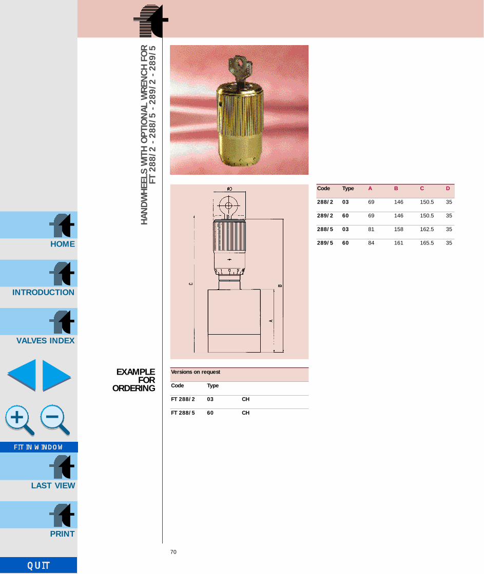
Code Type A B C D
288/2 03 69 146 150.5 35
289/2 60 69 146 150.5 35
288/5 03 81 158 162.5 35
289/5 60 84 161 165.5 35
EXAMPLEFOR
ORDERING
Versions on request
Code Type
FT 288/2 03 CH
FT 288/5 60 CH
GB-TognellaxCD 20/08/2001 11:56 Pagina 72

INTRODUCTION
HOME
VALVES INDEX
LAST VIEW
BALL VALVES
71
FT 221/1FT 221/3
GB-TognellaxCD 20/08/2001 11:56 Pagina 73

INTRODUCTION
HOME
VALVES INDEX
LAST VIEW
FT 221/1
72
BALL
VALV
ES
MATERIALS
High pressure two-way ball valves
Used to obtain a quick flow shut-off, avoiding noticeablepressure drop, the FT 221/1 ball valves are designed toobtain perfect sealing, easy and quick operation under highpressures conditions.Working pressure up to 500 bar most fluids.
CODE FT 221/1 Type DN PN A B C D E F nG CH Weight Fixing holes upon requestkg L M nL
18 4 500 44.5 71 33.5 37 13 115 1/8”G 9 0.300 29 27.5 4.5
14 6 500 44.5 71 33.5 37 13 115 1/4”G 9 0.374 29 27.5 4.5
38 10 500 50 72 39 43 16.5 115 3/8”G 9 0.559 35 35 5.5
12 13 500 51 85 40 48 17 115 1/2”G 9 0.655 39 35.5 6.5
34 20 320 71.5 97 56 63 24 160 3/4”G 14 1.564 50 49.5 6.5
100 25 320 76 113 60 67 26.5 160 1”G 14 2.082 54 54 6.5
114 32 320 106 110 85 80 39 210 1 1/4” G 17 2.107 – – –
112 40 320 112.5 130 92 85 41.5 210 1 1/2”G 17 3.698 – – –
200 50 320 132 140 111 100 50 210 2”G 19 6.070 – – –
Body Carbon steelControl stem Chrome-plated steelBall Chrome-plated steelOr NitrileBall seal PTFE
EXAMPLEFOR
ORDERING
Code Type
FT 221/1 34
GB-TognellaxCD 20/08/2001 11:56 Pagina 74

INTRODUCTION
HOME
VALVES INDEX
LAST VIEW
FT 221/3
73
BALL
VALV
ES
MATERIALS
CODE FT221/3
EXAMPLEFOR ORDERING
High pressure three-way ball valves
Used to obtain a quick flow shut-off, avoiding noticeablepressure drop, the FT 221/3 ball valves are designed toobtain perfect sealing, easy and quick operation underpressures.Working pressure up to 315 bar most fluids.
Type DN PN A B C D E F G H L M nN Weight Fixing holes upon requestkg P Q nR
18 4 500 33.5 13 71 36 8 44.5 13 9 115 44 1/8”G 0.415 27.5 27 M4
14 6 500 33.5 13 71 36 8 44.5 13 9 115 44 1/4”G 0.572 27.5 27 5.5
38 10 500 39 16.5 72 43 8 50 16.5 9 115 51 3/8”G 0.692 35 33 5.5
12 13 500 40.5 17.5 85 48 8 51.5 17.5 9 115 55 1/2”G 1.519 36 38 6.5
34 20 320 56.5 24.5 97 63 11 72 34.5 14 160 70 3/4”G 2.470 49.5 50 8.5
100 25 320 63.5 30 113 67 11 79.5 30 114 160 87.5 1”G 2.336 54 54 8.5
Body Carbon steelControl stem Chrome-plated steelBall Chrome-plated steelOr NitrileBall seal PTFE
Versions on request
Code Type
FT 221/3 34
GB-TognellaxCD 20/08/2001 11:56 Pagina 75

INTRODUCTION
HOME
VALVES INDEX
LAST VIEW
GB-TognellaxCD 20/08/2001 11:56 Pagina 76

INTRODUCTION
HOME
VALVES INDEX
LAST VIEW
PRESS-FORGED CONTROL VALVES IN BRASS-58
75
FT 1251/2-01FT 1251/2-02FT 1252/2-01FT 1252/2-02FT 1251/5-01FT 1253/5FT 1254/5
GB-TognellaxCD 20/08/2001 11:56 Pagina 77

INTRODUCTION
HOME
VALVES INDEX
LAST VIEW
FT 1251/2-01
76
PRES
S-FO
RGED
CO
NTR
OL
VALV
ESIN
BRA
SS-5
8
MATERIALS
CODE FT 1251/2-01
EXAMPLEFOR
ORDERING
In line double-acting needle control valves (Female/Female)
They allow for regulation of flow in both directionsSuitable for applications with air, gas and liquid in general.As an alternative to FT 257/2 where the working pressuredoes not exceed 210 bar and when ferrous materials can-not be used.Same basic characteristics as the FT 257 series:• accurate flow regulation;• efficient metallic sealing;• simple setting of flow rates;• secure against accidental needle withdrawal;• secure needle position with locking screw inserted
in the handwheel;• provisions for panel mounting, for which special lock
nut (G) is supplied on request.
For use with pressures up to 210 bar.
On request• Versions in stainless steel AISI 316 code FT 2251/2-01• Viton seals (V)• NPT threads• Handwheel in ABS (mp) plastic• Complete with lock nut (G)
Type A B C D E F F1 G H L CH Weight kgUNI 338
18 1/8”G 8 40 55 4 22 40 12 M15x1 9.5 15 0.105
14 1/4”G 12 46 57 4.5 22 40 11.5 M17x1 11 17 0.122
38 3/8”G 13 55 69 7 27 50 12.5 M20x1 15 22 0.233
12 1/2”G 16 70 82 10 33 70 13 M25x1.5 19 27 0.455
34 3/4”G 20 91 100 12 38 80 15 M30x1.5 22 34 0.860
Body OT 58 - UNI 5705 - Nickel platedNeedle X 10 Cr Ni S 1809 - UNI 6900Or NitrileAntiextrusion ring PTFEHandwheel ma GD - Al Si 12
UNI 5706 aluminiumHandwheel mp ABS plastic
Note: Instructions for panel mounting on page 86
Accessories on request
Code Type Lock Viton Handwheel ABSnut seal plastic
Brass FT 1251/2-01 38 G V mp
Stainl. steel FT 2251/2-01 14 G V mp
GB-TognellaxCD 20/08/2001 11:56 Pagina 78
INTRODUCTION
HOME
VALVES INDEX
LAST VIEW
FT 1251/2-02
77
PRES
S-FO
RGED
CO
NTR
OL
VALV
ESIN
BRA
SS-5
8
MATERIALS
CODE FT 1251/2-02
EXAMPLEFOR ORDERING
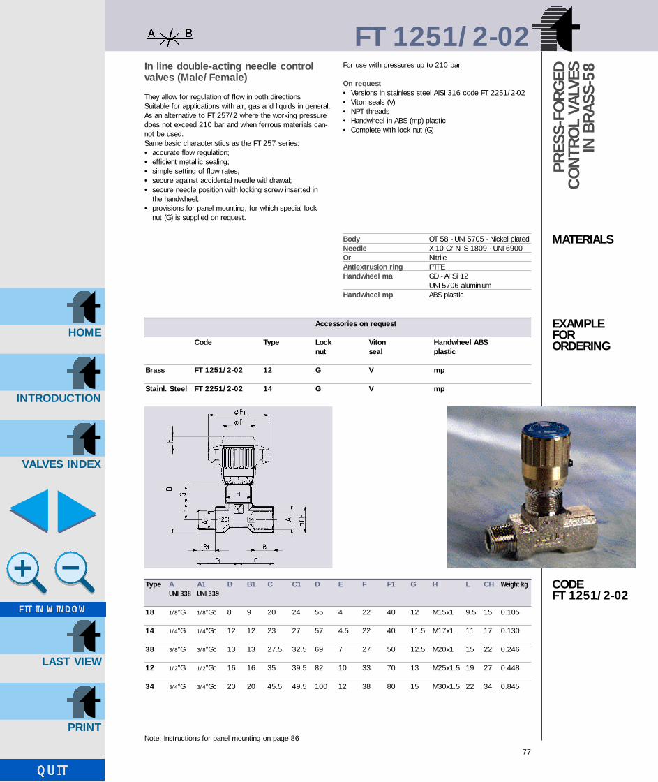
In line double-acting needle control valves (Male/Female)
They allow for regulation of flow in both directionsSuitable for applications with air, gas and liquids in general.As an alternative to FT 257/2 where the working pressuredoes not exceed 210 bar and when ferrous materials can-not be used.Same basic characteristics as the FT 257 series:• accurate flow regulation;• efficient metallic sealing;• simple setting of flow rates;• secure against accidental needle withdrawal;• secure needle position with locking screw inserted in
the handwheel;• provisions for panel mounting, for which special lock
nut (G) is supplied on request.
For use with pressures up to 210 bar.
On request• Versions in stainless steel AISI 316 code FT 2251/2-02• Viton seals (V)• NPT threads• Handwheel in ABS (mp) plastic• Complete with lock nut (G)
Type A A1 B B1 C C1 D E F F1 G H L CH Weight kgUNI 338 UNI 339
18 1/8”G 1/8”Gc 8 9 20 24 55 4 22 40 12 M15x1 9.5 15 0.105
14 1/4”G 1/4”Gc 12 12 23 27 57 4.5 22 40 11.5 M17x1 11 17 0.130
38 3/8”G 3/8”Gc 13 13 27.5 32.5 69 7 27 50 12.5 M20x1 15 22 0.246
12 1/2”G 1/2”Gc 16 16 35 39.5 82 10 33 70 13 M25x1.5 19 27 0.448
34 3/4”G 3/4”Gc 20 20 45.5 49.5 100 12 38 80 15 M30x1.5 22 34 0.845
Body OT 58 - UNI 5705 - Nickel platedNeedle X 10 Cr Ni S 1809 - UNI 6900Or NitrileAntiextrusion ring PTFEHandwheel ma GD - Al Si 12
UNI 5706 aluminiumHandwheel mp ABS plastic
Note: Instructions for panel mounting on page 86
Accessories on request
Code Type Lock Viton Handwheel ABSnut seal plastic
Brass FT 1251/2-02 12 G V mp
Stainl. Steel FT 2251/2-02 14 G V mp
GB-TognellaxCD 20/08/2001 11:56 Pagina 79

INTRODUCTION
HOME
VALVES INDEX
LAST VIEW
FT 1252/2-01
78
PRES
S-FO
RGED
CO
NTR
OL
VALV
ESIN
BRA
SS-5
8
MATERIALS
CODE FT 1252/2-01
EXAMPLEFOR
ORDERING
90° angle double-acting needle control valves (Female/Female)
They allow for regulation of flow in both directionsSuitable for applications with air, gas and liquids in general.As an alternative to FT 257/2 where the working pressuredoes not exceed 210 bar and when ferrous materials can-not be used.Same basic characteristics as the FT 257 series:• accurate flow regulation;• efficient metallic sealing;• simple setting of flow rates;• secure against accidental needle withdrawal;• secure needle position with locking screw inserted
in the handwheel;• provisions for panel mounting, for which special lock
nut (G) is supplied on request.
They allow use with pressures up to 210 bar.
On request• Viton seals (V)• NPT threads• Handwheel in ABS (mp) plastic• Complete with lock nut (G)
Type A B C D E F F1 G H L CH Weight kgUNI 338
18 1/8”G 8 21 69 4 22 40 12 M15x1 9.5 15 0.105
14 1/4”G 12 25 74 4.5 22 40 12 M17x1 11 17 0.136
38 3/8”G 13 29.5 88 7 27 50 11.5 M20x1 15 22 0.248
12 1/2”G 16 36 105 10 33 70 13 M25x1.5 19 27 0.454
Body OT 58 - UNI 5705 - Nickel platedNeedle X 10 Cr Ni S 1809 - UNI 6900Or NitrileAntiextrusion ring PTFEHandwheel ma GD - Al Si 12
UNI 5706 aluminiumHandwheel mp ABS plastic
Note: Instructions for panel mounting on page 86
Accessories on request
Code Type Lock Viton Handwheel ABSnut seal plastic
Brass FT 1252/2-01 38 G V mp
GB-TognellaxCD 20/08/2001 11:56 Pagina 80

INTRODUCTION
HOME
VALVES INDEX
LAST VIEW
FT 1252/2-02
79
PRES
S-FO
RGED
CO
NTR
OL
VALV
ESIN
BRA
SS-5
8
MATERIALS
CODE FT 1252/2-02
EXAMPLEFOR ORDERING
Note: Instructions for panel mounting on page 86
90° angle double-acting needle controlvalves (Male/Female)
They allow for regulation of flow in both directionsSuitable for applications with air, gas and liquids in general.As an alternative to FT 257/2 where the working pressuredoes not exceed 210 bar and when ferrous materials can-not be used.Same basic characteristics as the FT 257 series:• accurate flow regulation;• full shut off via metal seal;• simple setting of flowrates;• secure against accidental needle withdrawal;• secure needle position with locking screw inserted
in the handwheel;• provisions for panel mounting, for which special lock
nut (G) is supplied on request.
They allow use with pressures up to 210 bar.
On request• Viton seals (V)• NPT threads• Handwheel in ABS (mp) plastic• Complete with lock nut (G)
Type A A1 B B1 C C1 D E F F1 G H L CH Weight kgUNI 339 UNI 338
18 1/8”Gc 1/8”G 8 9 21 21 70 4 22 40 12 M15x1 9.5 15 0.102
14 1/4”Gc 1/4”G 12 12 25 25 74 4.5 22 40 12 M17x1 11 17 0.132
38 3/8”Gc 3/8”G 13 13 29.5 29.5 88 7 27 50 11.5 M20x1 15 22 0.245
12 1/2”Gc 1/2”G 16 16 36 36 105 10 33 70 13 M25x1.5 19 27 0.440
Body OT 58 - UNI 5705 - Nickel platedNeedle X 10 Cr Ni S 1809 - UNI 6900Or NitrileAntiextrusion ring PTFEHandwheel ma GD - Al Si 12
UNI 5706 aluminiumHandwheel mp ABS plastic
Accessories on request
Code Type Lock Viton Handwheel ABSnut seal plastic
Brass FT 1252/2-02 12 G V mp
GB-TognellaxCD 20/08/2001 11:56 Pagina 81

INTRODUCTION
HOME
VALVES INDEX
LAST VIEW
80
FT 1251/5-01
PRES
S-FO
RGED
CO
NTR
OL
VALV
ESIN
BRA
SS-5
8
MATERIALS
CODE FT 1251/5-01
EXAMPLEFOR
ORDERING
In line single-acting needle control valves (Female/Female)
They allow for regulation of flow in one direction and fullfree flow in the opposed direction.As an alternative to FT 257/5 where the working pressuredoes not exceed 210 bar and when ferrous materials can-not be used.Suitable for application with air, gas and liquids in general.Same basic characteristics as the FT 257 series:• full shut off via metal seal;• simple setting of flow rates;• secure against accidental needle withdrawal;• secure needle position with locking screw inserted
in the handwheel;• provisions for panel mounting, for which special lock
nut (G) is supplied (on request only).
Max. working pressure is 210 bar.
On request• Seals in Viton (V)• NPT threads• Handwheel in ABS (mp) plastic• Complete with lock nut (G)
Type A B C D E F F1 G H L CH Weight kgUNI 338
14 1/4”G 12 56 57 4.5 22 40 11.5 M17x1 11 17 0.138
38 3/8”G 13 64.5 69 7 27 50 12.5 M20x1 15 22 0.259
12 1/2”G 16 87 82 10 33 70 13 M25x1.5 19 27 0.499
34 3/4”G 20 115 100 12 38 80 15 M30x1.5 22 34 0.975
Body OT 58 - UNI 5705 - Nickel platedNeedle X 10 Cr Ni S 1809 - UNI 6900Or NitrileAntiextrusion ring PTFEHandwheel ma GD - Al Si 12
UNI 5706 aluminiumHandwheel mp ABS plasticSpring AISI 302Ball UNI 100 C 6Ball guide Nylon 66 + carbon fibre
Accessories on request
Code Type Lock Viton Handwheel ABSnut seal plastic
Brass FT 1251/5-01 38 G V mp
Note: Instructions for panel mounting on page 86
GB-TognellaxCD 20/08/2001 11:56 Pagina 82

INTRODUCTION
HOME
VALVES INDEX
LAST VIEW
FT 1253/5
81
PRES
S-FO
RGED
CO
NTR
OL
VALV
ESIN
BRA
SS-5
8
MATERIALS
CODE FT 1253/5
EXAMPLEFOR ORDERING
Single-acting needle control valves
They ensure an accurate control of the fluid in one direc-tions and allow for free passage in the opposed directionAs an alternative to FT 257/5 where the working pressuredoes not exceed 210 bar and when ferrous materials can-not be used.Suitable for application with air, gas and liquids in general.Same basic characteristics as the FT 257 series:• full shut off via metal seal;• simple setting of flow rates;• secure against accidental needle withdrawal;• secure needle position with locking screw inserted
in the handwheel;• provisions for panel mounting, for which special lock nut(G) is supplied (on request only).Max. working pressure is 210 bar.
On request• Versions in stainless steel AISI 316 code FT 2253/5• Seals in Viton (V)• NPT threads• Handwheel in ABS (mp) plastic• Complete with lock nut (G)
Body OT 58 - UNI 5705Nickel plated
Needle X 10 Cr Ni S 1809 - UNI 6900Or NitrileAntiextrusion ring PTFEHandwheel ma GD - Al Si 12
UNI 5706 aluminium
Versions on request Accessories on request
Code Connect. M/F Type Lock Viton Handwheel ABSnut seal plastic
Brass FT 1253/5 02 12 G V mp
Stainl. Steel FT 2253/5 02 18 G V mp
Type A B C D E F F1 G H L CH Weight kgUNI 338
18 1/8”G 8 40 55 4 22 40 12 M15x1 9.5 15 0.105
14 1/4”G 12 46 57 4.5 22 40 11.5 M17x1 11 17 0.135
38 3/8”G 13 55 69 7 27 50 12.5 M20x1 15 22 0.250
12 1/2”G 16 70 82 10 33 70 13 M25x1.5 19 27 0.460
34 3/4”G 20 91 100 12 38 80 15 M30x1.5 22 34 0.860
Note: Instructions for panel mounting on page 86
GB-TognellaxCD 20/08/2001 11:56 Pagina 83

INTRODUCTION
HOME
VALVES INDEX
LAST VIEW
FT 1254/5-01
82
90° single-acting needle control valves
They ensure an accurate control of the fluid in one directions and allow for free passage in the opposed directionAs an alternative to FT 257/5 where the working pressuredoes not exceed 210 bar and when ferrous materials cannot be used.Suitable for application with air, gas and liquids in general.Same basic characteristics as the FT 257 series:• full shut off via metal seal;• simple setting of flow rates;• secure against accidental needle withdrawal;• secure needle position with locking screw inserted
in the handwheel;• provisions for panel mounting, for which special lock nut
(G) is supplied (on request only).
Max. working pressure is 210 bar.
On request• Seals in Viton (V)• NPT threads• Handwheel in ABS (mp) plastic
Type A B C D E F F1 G H L CH Weight kgUNI 338
18 1/8”G 8 21 69 4 22 40 12 M15x1 9.5 15 0.105
14 1/4”G 12 25 74 4.5 22 40 11.5 M17x1 11 17 0.137
38 3/8”G 13 29.5 88 7 27 50 12.5 M20x1 15 22 0.251
12 1/2”G 16 36 105 10 33 70 13 M25x1.5 19 27 0.450
Body OT 58 - UNI 5705Nickel plated
Needle X 10 Cr Ni S 1809 - UNI 6900Or NitrileAntiextrusion ring PTFEHandwheel ma GD - Al Si 12
UNI 5706 aluminiumHandwheel mp ABS plastic
Versions Accessories on request on request
Code Connect. Type Lock nut Viton seal Handwheel ABSM/F plastic
Brass FT 1254/5 02 38 G V mp
Note: Instructions for panel mounting on page 86
PRES
S-FO
RGED
CO
NTR
OL
VALV
ESIN
BRA
SS-5
8
MATERIALS
CODE FT 1254/5-01
EXAMPLEFOR
ORDERING
GB-TognellaxCD 20/08/2001 11:56 Pagina 84

INTRODUCTION
HOME
VALVES INDEX
LAST VIEW
FT 1251/2-FT 1252/2 - FT 1251/5
83
FT 1251/2-1252/2-18
FT 1251/2-1252/2-1521/5-38
FT 1251/2-1252/2-14 FT 1251/5
Type Port section Max. working Working Filtration gradesq. mm pressure bar temperature °C µm absolute
18 7.07 210 -20°/+100° 25
14 12.57 210 -20°/+100° 25
38 19.64 210 -20°/+100° 25
12 50.27 210 -20°/+100° 25
34 78.54 210 -20°/+100° 25
Type Port section Max. working Working Filtration gradesq. mm pressure bar temperature °C µm absolute
14 12.57 210 -20°/+100° 25
38 19.64 210 -20°/+100° 25
12 50.27 210 -20°/+100° 25
34 78.54 210 -20°/+100° 25
TECHNICALDATAFT 1251/2FT 1252/2
TECHNICALDATAFT 1251/5
FLOWRATECURVES
GB-TognellaxCD 20/08/2001 11:57 Pagina 85

INTRODUCTION
HOME
VALVES INDEX
LAST VIEW
84
FT 1251/2-1252/2-1251/5-12 FT 1251/2-34
FT 1251/5-34 FT 1251/5
FLOWRATECURVES
FT 1251/2-FT 1252/2 - FT 1251/5
GB-TognellaxCD 20/08/2001 11:57 Pagina 86

INTRODUCTION
HOME
VALVES INDEX
LAST VIEW
FT 1253/5 - FT 1254/5
85
FLOWRATECURVES
Type Port section Max. working Working Filtration gradesq. mm pressure temperature µm absolute
bar °C
18 7.07 210 -20°/+100° 25
14 12.57 210 -20°/+100° 25
38 19.64 210 -20°/+100° 25
12 50.27 210 -20°/+100° 25
34 78.54 210 -20°/+100° 25
TECHNICALDATA
FT 1253/5-1254/5-18 FT 1253/5-1254/5-14
FT 1253/5-1254/5-38 FT 1253/5-1254/5-12
FT 1253/5-1254/5FT 1253/5-34
GB-TognellaxCD 20/08/2001 11:57 Pagina 87

INTRODUCTION
HOME
VALVES INDEX
LAST VIEW
SERIE FT 1250
86
DISASSEMBLYINSTRUCTIONSTO FIT PANELMOUNT NUT
1
2
3
4
5
67
8
9
A
n B
Guarnizioni di ricambio e ghiere
Type OR (7) BK (6) Ghiera (9) A max nB
18 2018 2018 FT 1203/18 5 16
14 2018 2018 FT 1203/14 5 18
38 2021 2021 FT 1203/38 5 21
12 108 108 FT 1203/12 6 26
34 2043 2043 FT 1203/34 6 31
Panel mounting
1° Loosen grub screw pressure dowel - item (4)
2° Remove plug - item (1)
3° Remove screw - item (2)
4° Pull off handwheel - item (3)
5° Insert ring FT 1203 - item (9) indicated in table (on request it is supplied with the valve)
(A) Max thickness
(B) Bore for panel mounting n
GB-TognellaxCD 20/08/2001 11:57 Pagina 88
INTRODUCTION
HOME
VALVES INDEX
LAST VIEW
87
FT 1237/2FT 1237/5FT 1247/2
FINE CONTROL NEEDLE VALVES
GB-TognellaxCD 20/08/2001 11:57 Pagina 89

INTRODUCTION
HOME
VALVES INDEX
LAST VIEW
88
FIN
EC
ON
TRO
LVA
LVES
MATERIALS
CODE 1237/2
EXAMPLEFOR
ORDERING
In line double-acting fine control needle valves
FT’s solution for applications requiring precise adjustementof small flow rates.For both hydraulic-pneumatic applications with flow rates upto 3 l/min max.same basic characteristics as the FT 1250 series:• full shut off via metal seal;• provision for panel mounting;• security against accidental needle withdrawal.
On request• NPT threads• Viton seals
Type A B C D E F G H L CH Weight kgUNI 338
18 1/8”G 8 40 55 4 22 12 M15x1 9.5 15 0.105
Body OT 58 - UNI 5705 - PassivatedNeedle X 10 Cr Ni S 1809 - UNI 6900Or NitrileAntiextrusion ring PTFEHandwheel ma. GD Al Si 12
UNI 5706 aluminium
Accessories on request
Code Type Lock Vitol nut seal
Brass FT 1237/2 18 G V
Note: Instructions for panel mounting on page 92
FT 1237/2
GB-TognellaxCD 20/08/2001 11:57 Pagina 90

INTRODUCTION
HOME
VALVES INDEX
LAST VIEW
FT 1237/5
89
FIN
E C
ON
TRO
LN
EED
LE V
ALVE
S
MATERIALS
CODE 1237/5
EXAMPLEFOR ORDERING
In line single-acting fine control needle valves
FT’s solution for applications requiring precise adjustementof small flow rates.For both hydraulic-pneumatic applications with flow rates upto 3 l/min max.same basic characteristics as the FT 1250 series:• full shut off via metal seal;• provision for panel mounting;• security against accidental needle withdrawal.
On request• NPT threads• Viton seals
Type A B C D E F G H L CH Weight kgUNI 338
18 1/8”G 8 46.5 55 4 22 12 M15x1 9.5 15 0.110
Body OT 58 - UNI 5705 - PassivatedNeedle X 10 Cr Ni S 1809 - UNI 6900Or NitrileAntiextrusion ring PTFEHandwheel GD Al Si 12
UNI 5706 aluminiumSpring AISI 302Ball UNI 100 C 6Ball guide Nylon 66 + carbon fibre
Accessories on request
Code Type Lock nut Viton seal
Brass FT 1237/5 18 G V
Note: Instructions for panel mounting on page 92
GB-TognellaxCD 20/08/2001 11:57 Pagina 91

INTRODUCTION
HOME
VALVES INDEX
LAST VIEW
FT 1247/2
90
FIN
E C
ON
TRO
LN
EED
LE V
ALVE
S
MATERIALS
CODE 1247/2
EXAMPLEFOR
ORDERING
Double-acting fine control needle val-ves cartridge mounted
FT’s solution for applications requiring precise adjustementof small flow rates.For both hydraulic-pneumatic applications with flow rates upto 3 l/min max.same basic characteristics as the FT 1250 series:• full shut off via metal seal;• security against accidental needle withdrawal.
On request• Viton seals
Type A B E F G H L CH Weight kg (1) OR (2) BKUNI 4534
18 M15x1 12 20.5 22 34.5 55 8 22 0.069 108 108
Body OT 58 - UNI 5705 - PassivatedNeedle X 10 Cr Ni S 1809 - UNI 6900Or NitrileAntiextrusion ring PTFEHandwheel GD Al Si 12 - UNI 5706
aluminium
Accessories on request
Code Type Viton seal
FT 1247/2 18 V
Note: Instructions for panel mounting on page 93
GB-TognellaxCD 20/08/2001 11:57 Pagina 92

INTRODUCTION
HOME
VALVES INDEX
LAST VIEW
FT 1237/2-FT 1237/5-FT 1247/2
91
FT 1237/2-1237/5-1247/2-18
FT 1237/5-18
Type Port section Max. working Working Filtrationsq. mm pressure temperature grade
bar °C µm
18 3,14 210 -20°/+100° 25
TECHNICALDATA
FLOWRATECURVES
GB-TognellaxCD 20/08/2001 11:57 Pagina 93

INTRODUCTION
HOME
VALVES INDEX
LAST VIEW
SERIE FT 1237
92
DISASSEMBLYINSTRUCTIONSTO FIT PANELMOUNT NUT
1
2
3
4
5
67
8
9
A
B
Panel mounting
1° Unscrew handle lock screw - item (4)
2° Remove cover plate - item (1)
3° Remove screw - item (2)
4° Pull off handwheel - item (3)
5° Insert ring FT 1203 - item (9) indicated in table (on request it is supplied with the valve)
Seal and lock nut spare parts
Type 18
(7) OR 2018
(6) Antiextrusion ring 2018
(9) Lock nut KM KM2(FT 202/2)
Thickness A max 6
Bore for panel mounting n B 16
GB-TognellaxCD 20/08/2001 11:57 Pagina 94

INTRODUCTION
HOME
VALVES INDEX
LAST VIEW
93
MOUNTING SCHEMES FORSEATS OF FT 1247/2 VALVES CARTRIDGEMOUNTED
Sealing achieved by O-ring on flat seals
Type A B C D E E1 F G H L M Sm ORUNI 4354
18 23 19 2 M15x1 14 13 11 12 21.5 4 11.5 0.5 3056
Sealing achieved by O-ring seals on conical seat
Type A nB C D E F ØG H ∆L M Sm ORUNI 4534
18 16.2 M15x1 0.25 14 13 11 12 21.5 4 11.5 0.5 205
Detail of machining which may beexecuted in alternative to the conical one, eliminating dimension E1
Detail of machining which maybe executed in alternative tothe conical one, eliminating dimension E1
Sealing achieved by Bonded seals
Type A C D E E1 F G H L M Sm Bonded sealUNI 4534
18 23 1 M15x1 13 12 9 12 20 4 10.3 0.5 400-512
Flat seal Bonded seal
Conical seat
GB-TognellaxCD 20/08/2001 11:57 Pagina 95

INTRODUCTION
HOME
VALVES INDEX
LAST VIEW
GB-TognellaxCD 20/08/2001 11:57 Pagina 96

INTRODUCTION
HOME
VALVES INDEX
LAST VIEW
GAUGE ISOLATORVALVES
95
FT 290FT 291FT 292FT 293
GB-TognellaxCD(98/124) 20/08/2001 12:01 Pagina 1
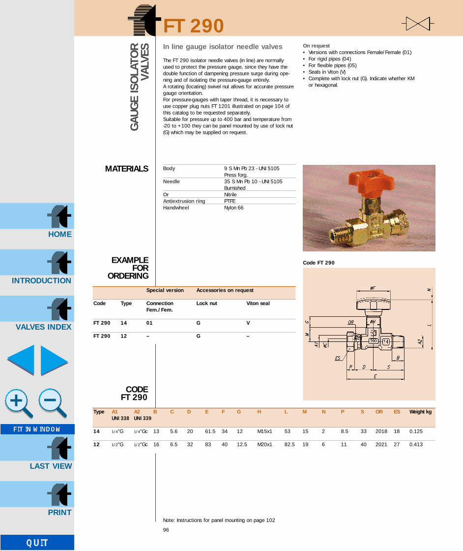
INTRODUCTION
HOME
VALVES INDEX
LAST VIEW
FT 290
96
GAU
GE
ISO
LATO
RVA
LVES
MATERIALS
EXAMPLEFOR
ORDERING
In line gauge isolator needle valves
The FT 290 isolator needle valves (in line) are normallyused to protect the pressure gauge, since they have thedouble function of dampening pressure surge during ope-ning and of isolating the pressure-gauge entirely.A rotating (locating) swivel nut allows for accurate pressuregauge orientation.For pressure-gauges with taper thread, it is necessary touse copper plug nuts FT 1201 illustrated on page 104 ofthis catalog to be requested separately.Suitable for pressure up to 400 bar and temperature from-20 to +100 they can be panel mounted by use of lock nut(G) which may be supplied on request.
On request• Versions with connections Female/Female (01)• For rigid pipes (04)• For flexible pipes (05)• Seals in Viton (V)• Complete with lock nut (G). Indicate whether KM
or hexagonal.
CODE FT 290
Body 9 S Mn Pb 23 - UNI 5105 Press forg.
Needle 35 S Mn Pb 10 - UNI 5105 Burnished
Or NitrileAntiextrusion ring PTFEHandwheel Nylon 66
Note: Instructions for panel mounting on page 102
Special version Accessories on request
Code Type Connection Lock nut Viton sealFem./Fem.
FT 290 14 01 G V
FT 290 12 – G –
Type A1 A2 B C D E F G H L M N P S OR ES Weight kgUNI 338 UNI 339
14 1/4”G 1/4”Gc 13 5.6 20 61.5 34 12 M15x1 53 15 2 8.5 33 2018 18 0.125
12 1/2”G 1/2”Gc 16 6.5 32 83 40 12.5 M20x1 82.5 19 6 11 40 2021 27 0.413
Code FT 290
GB-TognellaxCD(98/124) 20/08/2001 12:01 Pagina 2

INTRODUCTION
HOME
VALVES INDEX
LAST VIEW
FT 290
97
GAU
GE
ISO
LATO
RVA
LVES
Code FT 290-05Connection: flexible pipes DIN 3861
DIN 7611
Special versions only for type 14Supplied on request for quantities of atleast 200 pieces
Code FT 290-01Connection: Female-Female
Code FT 290-04Connection: rigid pipes - DIN 2353
A B1 B2 B3 C D E1 E2 E3 F G H L M N P R S1 S2 S3 OR ES Weight kgUNI 338
1/4”G 11 15 6.5 5.6 20 54.5 69.5 66 34 12 M15x1 53 15 2 8.5 6 25 25 30 2108 18 01 0,12504 0,15005 0,145
GB-TognellaxCD(98/124) 20/08/2001 12:01 Pagina 3

INTRODUCTION
HOME
VALVES INDEX
LAST VIEW
FT 291
98
GAU
GE
ISO
LATO
RVA
LVES
MATERIALS
CODE FT 291
EXAMPLEFOR
ORDERING
90° angle gauge isolator needle valves
The FT 291 isolator needle valves (angle) are normally usedto protect the pressure gauge since they have the doublefunction of dampening pressure surge during opening andof isolating the pressure-gauge entirely.A rotating (locating) swivel nut allows for accurate pressuregauge orientation.For pressure - gauges with taper threads, it will be neces-sary to use copper plug nuts FT 1201 illustrated on page104 of this catalog to be requested separately.Provided with connector FT 299-24 (see page 103) theyalso allow the connection of “Pressure gauges with connection 1/2” Gas”. (As alternative it is advisable to usethe mod. FT 290-12).Suitable for pressure up to 400 bar and temperature from -20 to +100 they can be panel mounted by use of
lock nut (G) which may be supplied on request.
On request• Versions with connections Female/Female (01)• For rigid pipes (04)• For flexible pipes (05)• Seals in Viton (V)• Complete with lock nut (G). Indicate whether KM
or hexagonal.
Body 9 S Mn Pb 23 - UNI 5105Press forg.
Needle 35 S Mn Pb 10 - UNI 5105Brunished
Or NitrileAntiextrusion ring PTFEHandwheel Nylon 66
Note: Instructions for panel mounting on page 102
Accessories on request
Code Connections Lock nut Viton sealFem./Fem.
FT 291 01 G V
A1 A2 B C D E F G H L M N P Q ES OR Weight kg.UNI 338 UNI 339
1/4”G 1/4”Gc 13.5 5.6 22 40 34 10 M15x1 66 11 2 8.5 28 18 2108 0.105
Code FT 291
GB-TognellaxCD(98/124) 20/08/2001 12:01 Pagina 4

INTRODUCTION
HOME
VALVES INDEX
LAST VIEW
FT 291
99
GAU
GE
ISO
LATO
RVA
LVES
Code FT 291-05Connection: flexible pipes DIN 3861
DIN 7611
Special versionsSupplied on request for quantities of atleast 200 pieces
Code FT 291-01Connection: Female-Female
Code FT 291-04Connection: rigid pipes - DIN 2353
A B1 B2 B3 C D E F G H L1 L2 L3 M N P Q1 Q2 Q3 R ES OR Weight kgUNI 338
1/4”G 11 15 6.5 5.6 22 40 34 10 M15x1 65 73 69.5 11 2 9.5 27 20 25 6 18 2018 01 0,12504 0,13505 0,130
GB-TognellaxCD(98/124) 20/08/2001 12:01 Pagina 5

INTRODUCTION
HOME
VALVES INDEX
LAST VIEW
FT 292
100
GAU
GE
ISO
LATO
RVA
LVES
MATERIALS
EXAMPLEFOR
ORDERING
Push-button gauge isolator valves
The new FT 292 push-button isolator valves are used toprotect pressure-gauges, since they have the double func-tion of dampening the pressure surge during opening andof isolating the pressure-gauge entirely.A reading is obtained by depressing the button. Releasingthe button shuts off the flow to the gauge with residualpressure being automatically drained.The button can be locked to give a continuos reading.The maximum release pressure is 50 Kg/sq cm.Panel mounting facility.Panel mounting fixtures are supplied only if expressly reque-sted, indicate whether KM or hexagonal.Complete with connector FT 299 (see page 103), theyallow for full location orientation for ease of reading.They may be used for working pressures up to 400 bar.
Body 9 S Mn Pb 23UNI 5105 - Press forg.
Cursor 35 S Mn Pb 10 - UNI 5105Heat treatm.
Push-button Nylon 66Or NitrileWeight kg 0.265
Accessories on request
Code Panel mounting nut Name plate
FT 292 G T
n A B C
1/4”G 45 80
1/2”G 50 85
GB-TognellaxCD(98/124) 20/08/2001 12:01 Pagina 6

INTRODUCTION
HOME
VALVES INDEX
LAST VIEW
FT 293
101
GAU
GE
ISO
LATO
RVA
LVES
MATERIALS
Push button gauge isolator valves - manifold mounted
The new FT 293 push-button isolator valves are used toprotect pressure-gauges, since they have the double func-tion of dampening the pressure surge during opening andof isolating the pressure-gauge fentirely.A reading is obtained by depressing the button. Releasingthe button shuts off the flow to the gauge with residualpressure being automatically drained.Complete with connector FT 299 (see page 103), theyallow for full location orientation for ease reading.They may be used for working pressures up to 400 bar.
Body 9 S Mn Pb 23 - UNI 5105Press forg.
Cursor 35 S Mn Pb 10 - UNI 5105Heat treatm.
Push-button Nylon 66Or NitrileWeight kg 0.890
EXAMPLEFOR ORDERING
Versions on request
Code FT 293-03
FT 293 FT 293-03
nA 1/4”G 1/2”GB 36.5 40.5C 75.5 82
nA 1/4”G 1/2”GB 36.5 40.5C 75.5 82
GB-TognellaxCD(98/124) 20/08/2001 12:01 Pagina 7

INTRODUCTION
HOME
VALVES INDEX
LAST VIEW
SERIE FT 290 - 291
102
Panel mounting
1° Remove screw - item (1)
2° Pull off handwheel - item (2)
3° Insert ring KM type (FT 202) or exagonal (FT 205)
DISASSEMBLYINSTRUCTIONS TO FIT PANELMOUNT NUT
1
Seal and look nut spare parts
(3) OR (4) BK (5) Antiextr.ring on request A max nB
2018 2018 KM 2 hexagonal type 5 16
(FT 202/2) FT 205
2
nB
A
5
4
3
GB-TognellaxCD(98/124) 20/08/2001 12:01 Pagina 8

INTRODUCTION
HOME
VALVES INDEX
LAST VIEW
FT 299
103
ADAP
TOR
MATERIALS
CODE FT 299
EXAMPLEFOR ORDERING
Pressure gauge swivel adaptors - 400 bar ratedAdaptors FT 299 allow the connection of a pressure gaugedirect to the system. They provide for correct dial orienta-tion.The adaptor has a built in ‘O-ring’ seal for use with pressuregauges with sealing nipple to DIN 16288.The oil flow is restricted to the gauge dampen any pressureshock surges.A gasket, supplied as current product and inserted in therotating nut, impedes any blow-by between fitting and pres-sure gauge. In case the pressure-gauge is provided with ataper thread, it is necessary to use copper plug nuts FT1201 on page 104 of this catalogue, to be requested sepa-rately.Max. working pressure is 400 bar.
Body 9 S Mn Pb 23 - UNI 5105Nut 9 S Mn Pb 23 - UNI 5105Or Nitrile
Type A B C D E OR CH1 CH2 Weight kgUNI 338 UNI 339
88 1/8”G 1/8”Gc 9 22 7.5 2010 14 12 0.021
44 1/4”G 1/4”Gc 13 27 9.5 2018 18 17 0.040
42 1/4”G 1/4”Gc 16 31 9.5 2018 18 22 0.068
24 1/2”G 1/2”Gc 13 31 11 108 27 22 0.090
22 1/2”G 1/2”Gc 16 34 11 108 27 22 0.100
On request with cylindrical thread
Code Type
FT 299 44
GB-TognellaxCD(98/124) 20/08/2001 12:01 Pagina 9

INTRODUCTION
HOME
VALVES INDEX
LAST VIEW
104
FT 1201
CO
PPER
GAU
GE
SEAL
S
MATERIALS
EXAMPLEFOR
ORDERING
Type A B C Weight kg/100 piecesUNI 338
14 1/4”G 6.5 5.5 0.200
12 1/2”G 8 6.5 0.700
For use with pressure gauges with sealing nipple to DIN 16288.
Cu - DHP - UNI 5649
Code Type
FT 1201 14
CODEFT 1201
GB-TognellaxCD(98/124) 20/08/2001 12:01 Pagina 10

INTRODUCTION
HOME
VALVES INDEX
LAST VIEW
CALCULATION FORMULAS
GB-TognellaxCD(98/124) 20/08/2001 12:02 Pagina 11

INTRODUCTION
HOME
VALVES INDEX
LAST VIEW
∆Pγ
∆Pγ water
1
bar
Lmin
1) Low viscosity liquids
2) Viscous liquids
CALCULATIONFORMULAS
ACCORDINGTO KvVALVE
COEFFICIENT
CALCULATION FORMULAS
Q = Kv .
∆P = P1 - P2
γ
Kv
Q = Kv .L
minQ = 26.674 .
Kv = 15.4 .
P1 = 8 . bar
P2 = 5 . bar
∆P = (P1 – P2)
γ water = 1
Lmin
Q = 8O . = 4.8 m3/h
Q
∆Pγ
Kv1 =
Kv2 = Kv1
Kv1 = 56.57 . Lmin
1
bar
2100 . Q
ν . KvZ =
ν
Q
Kv
ν = 23 . centistokes
γ water = 1 Kg/dm3
∆P = 2 . bar
FORMULA TO OBTAIN THE VALVE FLOWRATE
Z PARAMETER
Difference between downstream and upstreamvalve pressure (bar)
Water density
Valve coefficient depending on inner valve geometry.This value is obtained experimentally
Kinematic viscosity in centistokes
Valve flowrate in mc/h
Valve coefficient in mc/h
Valve coefficient in L/min
Downstream pressure
Upstream pressure
Pressure difference
Water density
Flowrate in L/min
Oil kinematic viscosity
Water density
Difference between downstream and upstream valve pressure
Valve flowrate requested
Valve coefficient forow viscosity liquidsin L/min
Valve coefficient correctedin mc/h
Ex:To determine the water flowrate in L/min with a valve FT 1251/2-12 with Kv = 15.4
Ex:To determine the suitable valve to let in 80 L/min oil with 2 bar ∆P
The Kv valve coefficient has to be multiplied by a factor F>1 with a viscous liquid.F is obtained through a Z parameter
.
.
Kv2 = 3.39 . m3
h1
bar.
106
GB-TognellaxCD(98/124) 20/08/2001 12:02 Pagina 12

INTRODUCTION
HOME
VALVES INDEX
LAST VIEW
107
Z parameter
Corrective factor
Coefficient of a valve suitableto let 80 L/min of oil with ν = 23centistokes with ∆Pof 2 bar
2100 . Q
ν . Kv2Z =
From the graphic it is possible to obtain the F
You find out the right Kv by moltiplying Kv1 by F:
Factor F as a function of the parameter Z
F = 1.25
Kv = F . Kv1
z = 238
Kv = 65.192 Lmin
1
bar.
30 50 100 200 500 1000 2100
➞ Z
2.8
2.6
2.4
2.2
2.0
1.8
1.6
1.4
1.2
0
➞F
CALCULATION FORMULAS
GB-TognellaxCD(98/124) 20/08/2001 12:02 Pagina 13

INTRODUCTION
HOME
VALVES INDEX
LAST VIEW
3) Gas
Mass flowrate
P1 - P2γ relat.
Qn = 28.81. Kv .
This formula is valid until the ratio P2/P1 does not go under the value P2crit./P1, corresponding to the sonic flow.For ratio P2/P1 inferior to such a value, flow is costant.As the value P2crit./P1 is about 0.5, the formula of the max. valve flowrate for gas is obtained through the following formula
1γ relat. . T1
Qnmax = 14.41. Kv . P1 .
∆P = P1 - P2
T1
γ
γ air
γ relat.
P2T1
FORMULA TO OBTAIN A STANDARDVALVE FLOWRATE (N-l/min)
FORMULA TO OBTAIN THE MAX VALVEFLOWRATE (N-l/min)
Difference between downstream and upstreamvalve pressure (bar)
Absolute gas temperature upstream the valve
Gas density
Air density
Relative gas/air density
Valve coefficient
Absolute temperature
Nitrogen density
Air density
Relative density
Critical pressure (for values superior to 0.5use the following formula
Flowrate in NL/min
Flowrate in Nmc/h
FORMULA TO DETERMINE THE VALVE MASS FLOWRATE
Valve flowrate in kg/h
Kmin . bar
Kv = 15.4 . L .
T1 = 273 . K + t
P crit. = P crit. = 0.714
T1 = 293 . K
kgm3
γ nitrogen = 1.1451 .
kgm3
γ air = 1.1839 .
P2P1
G = 5.726 .kgh
Qn = 83.342 . Lmin
Qn1 = 5 . Nmch
γ nitrogen
γ airγ relat. = γ relat. = 0.967
Ex:To determine nitrogen flowrate at 20°C with P1 = 7 bar and P2 = 5 bar of the valve FT 1251/2-12
108
.
P1 - P2γ relat.
Qn = 28.81. Kv .
Qn1 = Qn x 60/1000 = Nmc/h
P2T1
.
G = Qn1. γ
Then we have
G = Qn1 . γ nitrogen
CALCULATION FORMULAS
GB-TognellaxCD(98/124) 20/08/2001 12:02 Pagina 14

INTRODUCTION
HOME
VALVES INDEX
LAST VIEW
109
Air density under RSA conditions
Gas denomination
Middle specific gravity of some liquids at a pressure of 1 kg/cm2
Substance
AcetoneHydrochloric acid HCINitric acid HNO3
Sulphuric acid H2SO4
Sea waterGasolineBenzolEthyl etherPure glycerineOilWine
0.791.051.151.051.030.70.90.741.260.760.98
2015151515150001915
Specific gravity Grades centigrade
AcetyleneAmmoniaCarbon dioxideSulphur dioxideAirNitrogenStandard butaneChlorineHeliumHydrogenMethaneNeonCarbon monoxideOxygenOzonePropane
C2H2
NH3
CO2
SO2
N2
C4H10
Cl2HeH2
CH4
NeCOO2
O3
C3H8
1.07210.70581.80922.681.18391.14512.44732.94550.16340.08230.65650.82421.14451.30832.03261.8495
0.90560.59621.52822.263710.96722.06722.4880.1380.06950.55450.69620.96671.10511.71691.5622
Chemical formula Density kg/m3 Relative density
kgm3
RSA = REFERENCE STANDARD ATMOSPHERE ACCORDING TO UNI - ISO 8778
P = 1 . bar Pressure
Absolute temperature
Relativ humidity
Air density under RSA conditions
Ta = 293 . K
γ air = 1.1839 .
τ = 0.65
CALCULATION FORMULAS
GB-TognellaxCD(98/124) 20/08/2001 12:02 Pagina 15

INTRODUCTION
HOME
VALVES INDEX
LAST VIEW
110
1 0.447 0.45 0.585 1.48 2.72 0.767 0.87 1.02 2.7 4.53 1.145 1.26 2.25 4.11 6.424 1.43 1.65 3.33 6.48 8.765 1.8 1.95 3.81 9.06 13.55.75 2.05 2.265 5 10.365 14.626 2.37 5.4 10.8 156.25 2.58 5.5 11.37 15.66.75 5.7 12.51 16.87 13.08 17.48 14.52 18.488.75 15.6 19.929 20.410 23.7
Kv GRAPHICFOR VALVES
FT 1251/2FT 1251/5
Kv FACTORFREE FLOWFOR VALVEFT 1251/5
Kv GRAPHICFOR VALVEFT 1237/2MICROFINE
Knob turns Type 18 Type 14 Type 38 Type 12 Type 34
Knob turns 1237/2
25
20
15
10
5
0
The
Kv
valv
e co
effic
ient
Type 18
Type 14
Type 38
Type 12
Type 34
1 2 3 4 5 5.75 6 6.25 6.75 7 8 8.75 9 10
Knob turns
Type Kv14 10.838 20.7212 43.9734 53.94
1 2 3 4 5 6 7 8 9 10
Knob turns
0.9
0.8
0.7
0.6
0.5
0.4
0.3
0.2
0.1
0
The
Kv
valv
e co
effic
ient
1 0.012 0.1363 0.2454 0.355 0.4316 0.5127 0.68 0.6429 0.69310 0.775
1237
/2
CALCULATION FORMULAS
GB-TognellaxCD(98/124) 20/08/2001 12:02 Pagina 16

INTRODUCTION
HOME
VALVES INDEX
LAST VIEW
111
Kv GRAPHICFOR VALVEFT 257/2
Knob turns Type 18 Type 14 Type 38 Type 12 Type 34 Type 100 Type 114 Type 112 Type 20012 0.66 0.47 1.4 2.06 1.85 6.6 6.2 8.7 9.73 1.12 1.27 2.72 3.71 3.61 12.9 12.7 15.6 16.54 1.59 1.81 4.12 5.57 5.67 18.9 19.05 22.7 23.55 2.63 5.57 7.21 7.71 24.8 25.9 30.4 31.16 6.97 8.93 9.57 30.2 31.3 40.4 39.77 7.77 10.31 11.65 35.7 37.1 49 46.68 10.93 13.5 39.4 40.2 54.2 55.49 15.2 50.2 78.3 82.510 16.5 70 107.3
1 2 3 4 5 6 7 8 9 10
Knob turns
120
100
80
60
40
20
0
The
Kv
valv
e co
effic
ient
Type 18
Type 14
Type 38
Type 12
Type 34
Type 100
Type 114
Type 112
Type 200
CALCULATION FORMULAS
GB-TognellaxCD(98/124) 20/08/2001 12:02 Pagina 17

12 0.57 0.49 1.11 1.85 2.3 8.97 6.4 7 11.83 0.95 1.4 2.84 3.92 5.1 17.2 10.9 12.3 18.84 1.3 2.1 3.92 5.48 7.4 22.8 15.2 17.8 26.35 2.84 4.95 6.95 9.2 26.8 19.8 23.3 34.46 5.83 8.39 11.2 29.9 24.4 28.9 43.57 6.68 9.03 13.2 31.7 29.1 34.2 49.98 9.73 14.6 35.8 32.5 40.1 57.79 15.5 42.06 47.6 62.9 75.910 17.1 53.3 71.1 99.110.5 56.3
Knob turns Type 18 Type 14 Type 38 Type 12 Type 34 Type 100 Type 114 Type 112 Type 200
1 2 3 4 5 6 7 8 9 10 10.5
Knob turns
120
100
80
60
40
20
0
The
Kv
valv
e co
effic
ient
Type 18
Type 14
Type 38
Type 12
Type 34
Type 100
Type 114
Type 112
Type 200
112
Kv GRAPHICFOR VALVE
FT 257/5
Kv FACTORFREE FLOWFOR VALVE
FT 257/5
Type Kv18 4.2314 10.938 27.7412 48.9834 63.5100 77.5114 153.5112 205200 360
CALCULATION FORMULAS
INTRODUCTION
HOME
VALVES INDEX
LAST VIEW
GB-TognellaxCD(98/124) 20/08/2001 12:02 Pagina 18

INTRODUCTION
HOME
VALVES INDEX
LAST VIEW
113
Kv FACTORFOR VALVEFT 247/2
Knob turns Type 18 Microfine12 0.0233 0.1244 0.2265 0.3236 0.4687 0.5678 0.6919 0.83010 1
1 2 3 4 5 6 7 8 9 10 11 12 13
Knob turns
1.2
1
0.8
0.6
0.4
0.2
0
The
Kv
valv
e co
effic
ient
CALCULATION FORMULAS
GB-TognellaxCD(98/124) 20/08/2001 12:02 Pagina 19

12 0.62 0.72 0.93 1.69 2.62 5.983 0.95 1.56 1.69 3.5 5.01 11.754 1.28 2.38 2.91 5.15 7.4 17.325 1.77 3.52 4 6.37 9.69 23.26 2.41 5.65 8.04 12.16 28.047 2.6 10.31 14.93 32.68 2.7 17.32 37.59 18.64 4910 58.311 61.312 63.96
Knob turns Type 18 Type 14 Type 38 Type 12 Type 34 Type 100
1 2 3 4 5 6 7 8 9 10 11 12
Knob turns
70
60
50
40
30
20
10
0
The
Kv
valv
e co
effic
ient
Type 18
Type 14
Type 38
Type 12
Type 34
Type 100
114
Kv GRAPHICFOR VALVE
FT 267/2
CALCULATION FORMULAS
INTRODUCTION
HOME
VALVES INDEX
LAST VIEW
GB-TognellaxCD(98/124) 20/08/2001 12:02 Pagina 20

INTRODUCTION
HOME
VALVES INDEX
LAST VIEW
12 1.24 2.16 0.87 1.54 3.923 2.31 3.71 3.13 4.35 8.764 3.35 4.91 6 7.68 13.365 6.18 8.7 11.32 17.736 8.82 10.8 13.98 23.77 12.9 16.74 31.58 15.6 19.09 47.1
115
Kv GRAPHICFOR VALVEFT 267/5
Kv FACTORFREE FLOWFOR VALVEFT 267/5
Kv FACTORFREE FLOWFOR VALVEFT 267/6
Knob turns Type 14 Type 38 Type 12 Type 34 Type 100
50
45
40
35
30
25
20
15
10
5
0
The
Kv
valv
e co
effic
ient
Type 14
Type 38
Type 12
Type 34
Type 100
1 2 3 4 5 6 7 8
Knob turns
Type Kv14 9.738 23.712 40.234 51.5100 67
Type Kv14 17.938 26.712 49.434 69.9
CALCULATION FORMULAS
GB-TognellaxCD(98/124) 20/08/2001 12:02 Pagina 21
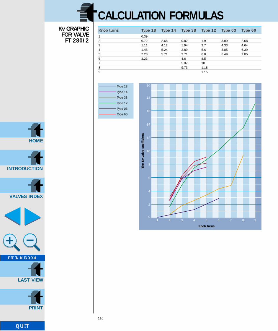
1 0.392 0.72 2.68 0.82 1.9 3.09 2.683 1.11 4.12 1.94 3.7 4.33 4.644 1.48 5.24 2.89 5.6 5.85 6.395 2.23 5.71 3.71 6.8 6.49 7.056 3.23 4.6 8.57 5.07 108 9.73 11.89 17.5
Knob turns Type 18 Type 14 Type 38 Type 12 Type 03 Type 60
1 2 3 4 5 6 7 8 9
Knob turns
20
18
16
14
12
10
8
6
4
2
0
The
Kv
valv
e co
effic
ient
Type 18
Type 14
Type 38
Type 12
Type 03
Type 60
116
Kv GRAPHICFOR VALVE
FT 280/2
CALCULATION FORMULAS
INTRODUCTION
HOME
VALVES INDEX
LAST VIEW
GB-TognellaxCD(98/124) 20/08/2001 12:02 Pagina 22

INTRODUCTION
HOME
VALVES INDEX
LAST VIEW
12 2.47 0.62 1.85 2.51 1.033 4 1.85 3.52 4.15 2.234 4.95 2.9 5.15 5.54 3.45 5.24 3.5 6.64 6.18 4.456 4.3 7.597 5 9.288 8.7 11.39 16.29
117
Kv GRAPHICFOR VALVEFT 280/5
Kv FACTORFREE FLOWFOR VALVEFT 280/5
Knob turns Type 14 Type 38 Type 12 Type 03 Type 60
18
16
14
12
10
8
6
4
2
0
The
Kv
valv
e co
effic
ient
Type 14
Type 38
Type 12
Type 03
Type 60
1 2 3 4 5 6 7 8 9
Knob turns
Type Kv14 6.838 13.1512 28.4503 7.2160 8.25
CALCULATION FORMULAS
GB-TognellaxCD(98/124) 20/08/2001 12:02 Pagina 23

Knob turns Fattore Kv1 0.00872 0.0873 0.1524 0.2485 0.3946 0.4937 0.5748 0.6419 0.710 0.9211 1.152
1 2 3 4 5 6 7 8 9 10 11
Knob turns
1.4
1.2
1
0.8
0.6
0.4
0.2
0
The
Kv
valv
e co
effic
ient
118
Kv FACTORFOR VALVE
FT 281/2
CALCULATION FORMULAS
INTRODUCTION
HOME
VALVES INDEX
LAST VIEW
GB-TognellaxCD(98/124) 20/08/2001 12:02 Pagina 24

INTRODUCTION
HOME
VALVES INDEX
LAST VIEW
Knob turns Fattore Kv1 0.0122 0.0873 0.1524 0.2485 0.3946 0.4937 0.5718 0.6419 0.710 0.91211 1.146
1 2 3 4 5 6 7 8 9 10 11
Knob turns
1.4
1.2
1
0.8
0.6
0.4
0.2
0
The
Kv
valv
e co
effic
ient
119
Kv FACTORFREE FLOWFOR VALVEFT 281/5
Type Kv03 5.58
Kv FACTORFOR VALVEFT 281/5
CALCULATION FORMULAS
GB-TognellaxCD(98/124) 20/08/2001 12:02 Pagina 25
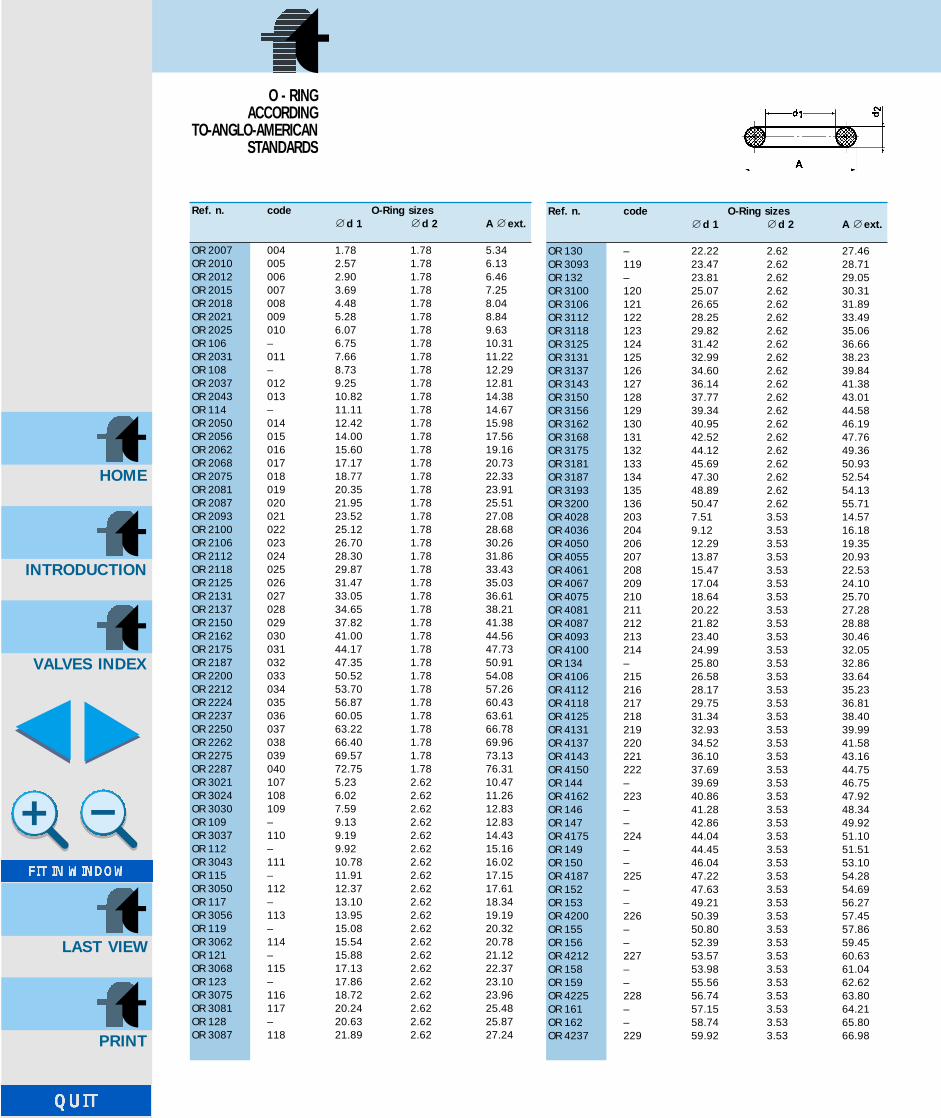
Ref. n. code O-Ring sizesnd 1 nd 2 A next.
OR 2007 004 1.78 1.78 5.34OR 2010 005 2.57 1.78 6.13OR 2012 006 2.90 1.78 6.46OR 2015 007 3.69 1.78 7.25OR 2018 008 4.48 1.78 8.04OR 2021 009 5.28 1.78 8.84OR 2025 010 6.07 1.78 9.63OR 106 – 6.75 1.78 10.31OR 2031 011 7.66 1.78 11.22OR 108 – 8.73 1.78 12.29OR 2037 012 9.25 1.78 12.81OR 2043 013 10.82 1.78 14.38OR 114 – 11.11 1.78 14.67OR 2050 014 12.42 1.78 15.98OR 2056 015 14.00 1.78 17.56OR 2062 016 15.60 1.78 19.16OR 2068 017 17.17 1.78 20.73OR 2075 018 18.77 1.78 22.33OR 2081 019 20.35 1.78 23.91OR 2087 020 21.95 1.78 25.51OR 2093 021 23.52 1.78 27.08OR 2100 022 25.12 1.78 28.68OR 2106 023 26.70 1.78 30.26OR 2112 024 28.30 1.78 31.86OR 2118 025 29.87 1.78 33.43OR 2125 026 31.47 1.78 35.03OR 2131 027 33.05 1.78 36.61OR 2137 028 34.65 1.78 38.21OR 2150 029 37.82 1.78 41.38OR 2162 030 41.00 1.78 44.56OR 2175 031 44.17 1.78 47.73OR 2187 032 47.35 1.78 50.91OR 2200 033 50.52 1.78 54.08OR 2212 034 53.70 1.78 57.26OR 2224 035 56.87 1.78 60.43OR 2237 036 60.05 1.78 63.61OR 2250 037 63.22 1.78 66.78OR 2262 038 66.40 1.78 69.96OR 2275 039 69.57 1.78 73.13OR 2287 040 72.75 1.78 76.31OR 3021 107 5.23 2.62 10.47OR 3024 108 6.02 2.62 11.26OR 3030 109 7.59 2.62 12.83OR 109 – 9.13 2.62 12.83OR 3037 110 9.19 2.62 14.43OR 112 – 9.92 2.62 15.16OR 3043 111 10.78 2.62 16.02OR 115 – 11.91 2.62 17.15OR 3050 112 12.37 2.62 17.61OR 117 – 13.10 2.62 18.34OR 3056 113 13.95 2.62 19.19OR 119 – 15.08 2.62 20.32OR 3062 114 15.54 2.62 20.78OR 121 – 15.88 2.62 21.12OR 3068 115 17.13 2.62 22.37OR 123 – 17.86 2.62 23.10OR 3075 116 18.72 2.62 23.96OR 3081 117 20.24 2.62 25.48OR 128 – 20.63 2.62 25.87OR 3087 118 21.89 2.62 27.24
Ref. n. code O-Ring sizesnd 1 nd 2 A next.
OR 130 – 22.22 2.62 27.46OR 3093 119 23.47 2.62 28.71OR 132 – 23.81 2.62 29.05OR 3100 120 25.07 2.62 30.31OR 3106 121 26.65 2.62 31.89OR 3112 122 28.25 2.62 33.49OR 3118 123 29.82 2.62 35.06OR 3125 124 31.42 2.62 36.66OR 3131 125 32.99 2.62 38.23OR 3137 126 34.60 2.62 39.84OR 3143 127 36.14 2.62 41.38OR 3150 128 37.77 2.62 43.01OR 3156 129 39.34 2.62 44.58OR 3162 130 40.95 2.62 46.19OR 3168 131 42.52 2.62 47.76OR 3175 132 44.12 2.62 49.36OR 3181 133 45.69 2.62 50.93OR 3187 134 47.30 2.62 52.54OR 3193 135 48.89 2.62 54.13OR 3200 136 50.47 2.62 55.71OR 4028 203 7.51 3.53 14.57OR 4036 204 9.12 3.53 16.18OR 4050 206 12.29 3.53 19.35OR 4055 207 13.87 3.53 20.93OR 4061 208 15.47 3.53 22.53OR 4067 209 17.04 3.53 24.10OR 4075 210 18.64 3.53 25.70OR 4081 211 20.22 3.53 27.28OR 4087 212 21.82 3.53 28.88OR 4093 213 23.40 3.53 30.46OR 4100 214 24.99 3.53 32.05OR 134 – 25.80 3.53 32.86OR 4106 215 26.58 3.53 33.64OR 4112 216 28.17 3.53 35.23OR 4118 217 29.75 3.53 36.81OR 4125 218 31.34 3.53 38.40OR 4131 219 32.93 3.53 39.99OR 4137 220 34.52 3.53 41.58OR 4143 221 36.10 3.53 43.16OR 4150 222 37.69 3.53 44.75OR 144 – 39.69 3.53 46.75OR 4162 223 40.86 3.53 47.92OR 146 – 41.28 3.53 48.34OR 147 – 42.86 3.53 49.92OR 4175 224 44.04 3.53 51.10OR 149 – 44.45 3.53 51.51OR 150 – 46.04 3.53 53.10OR 4187 225 47.22 3.53 54.28OR 152 – 47.63 3.53 54.69OR 153 – 49.21 3.53 56.27OR 4200 226 50.39 3.53 57.45OR 155 – 50.80 3.53 57.86OR 156 – 52.39 3.53 59.45OR 4212 227 53.57 3.53 60.63OR 158 – 53.98 3.53 61.04OR 159 – 55.56 3.53 62.62OR 4225 228 56.74 3.53 63.80OR 161 – 57.15 3.53 64.21OR 162 – 58.74 3.53 65.80OR 4237 229 59.92 3.53 66.98
O - RING ACCORDING
TO-ANGLO-AMERICANSTANDARDS
INTRODUCTION
HOME
VALVES INDEX
LAST VIEW
GB-TognellaxCD 1/10/2001 16:22 Pagina 122

INTRODUCTION
HOME
VALVES INDEX
LAST VIEW
EDIZIONE2001
EDITION2001
GB-TognellaxCD(98/124) 20/08/2001 12:02 Pagina 27

INTRODUCTION
HOME
VALVES INDEX
LAST VIEW
SALES
ITALIAALESSANDRIA
ANCONA AOSTA
AREZZO ASCOLI PICENO
ASTI BARI
BELLUNO BERGAMO BOLOGNA BOLZANO BRESCIA CAGLIARI
CAMPOBASSO CASERTA CATANIA
CHIETI COMO
COSENZA CREMONA
CUNEO FERRARA FIRENZE
FORLÌ FROSINONE
GENOVA LA SPEZIA
LATINA LECCE
LIVORNO LUCCA
MACERATA MANTOVA
MASSA CARRARA MATERA MILANO
MODENA NAPOLI PADOVA
PALERMO PARMA
PAVIA PERUGIA PESARO
PIACENZA PISA
PISTOIA PORDENONE
RAVENNA REGGIO EMILIA
ROMA ROVIGO SAVONA
SIENA SONDRIO TERAMO TORINO TRENTO TREVISO TRIESTE
UDINE VARESE VENEZIA
VERCELLI VERONA VICENZA VITERBO
ORGANIZATION
ESTEROAUSTRALIAAUSTRIA BELGIO BRASILECINACIPROCOLOMBIACOREADANIMARCA EGITTOFINLANDIA FRANCIA GERMANIA GRECIA INDONESIAINGHILTERRA ISRAELENORVEGIA NUOVA ZELANDAOLANDAPORTOGALLO REPUBBLICA CECASINGAPORESLOVENIASOUTH AFRICASPAGNASVEZIASVIZZERA TAIWANTURCHIAU.S.A.
F.lli Tognella S.p .A.COMPONENTI OLEODINAMICI PNEUMATICI
21019 Somma Lombardo (VA) ItalyVia Goito, 60Tel. 0331/988411Telefax 0331/988499e-mail [email protected]//www.tognella.it
GB-TognellaxCD(98/124) 20/08/2001 12:02 Pagina 28