flow measurement technology solutions for fluid ... -...
TRANSCRIPT

1
Solu
tio
ns f
or
Flu
id T
echn
olo
gy
rS SerieS
FlOw MeaSureMenT TECHNOLOGy
2
vOluMenSenSOren Der Baureihe vS
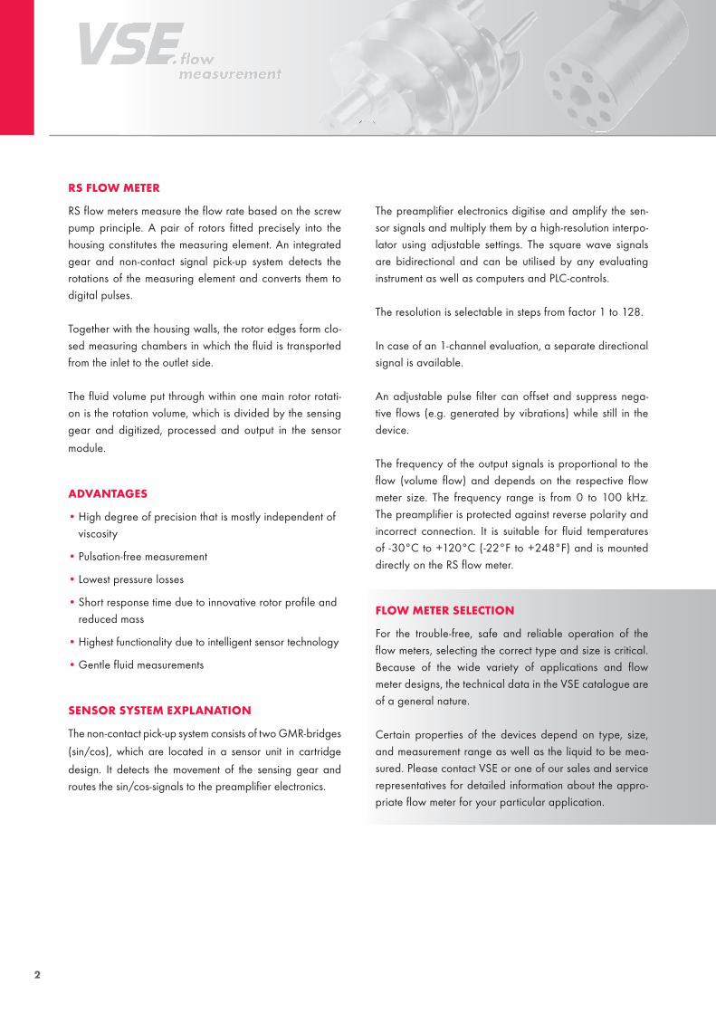
rS FlOw MeTer
RS flow meters measure the flow rate based on the screw pump principle. A pair of rotors fitted precisely into the housing constitutes the measuring element. An integrated gear and non-contact signal pick-up system detects the rotations of the measuring element and converts them to digital pulses.
Together with the housing walls, the rotor edges form clo-sed measuring chambers in which the fluid is transported from the inlet to the outlet side.
The fluid volume put through within one main rotor rotati-on is the rotation volume, which is divided by the sensing gear and digitized, processed and output in the sensor
module.
aDvanTageS
• High degree of precision that is mostly independent of viscosity
• Pulsation-free measurement
• Lowest pressure losses
• Short response time due to innovative rotor profile and reduced mass
• Highest functionality due to intelligent sensor technology
• Gentle fluid measurements
SenSOr SySTeM eXPlanaTiOn
The non-contact pick-up system consists of two GMR-bridges
(sin/cos), which are located in a sensor unit in cartridge
design. It detects the movement of the sensing gear and routes the sin/cos-signals to the preamplifier electronics.
The preamplifier electronics digitise and amplify the sen-sor signals and multiply them by a high-resolution interpo-lator using adjustable settings. The square wave signals are bidirectional and can be utilised by any evaluating instrument as well as computers and PLC-controls.
The resolution is selectable in steps from factor 1 to 128.
In case of an 1-channel evaluation, a separate directional signal is available.
An adjustable pulse filter can offset and suppress nega-tive flows (e.g. generated by vibrations) while still in the device.
The frequency of the output signals is proportional to the flow (volume flow) and depends on the respective flow meter size. The frequency range is from 0 to 100 kHz. The preamplifier is protected against reverse polarity and incorrect connection. It is suitable for fluid temperatures of -30°C to +120°C (-22°F to +248°F) and is mounted directly on the RS flow meter.
FlOw MeTer SelecTiOn
For the trouble-free, safe and reliable operation of the flow meters, selecting the correct type and size is critical. Because of the wide variety of applications and flow meter designs, the technical data in the VSE catalogue are of a general nature.
Certain properties of the devices depend on type, size, and measurement range as well as the liquid to be mea-sured. Please contact VSE or one of our sales and service representatives for detailed information about the appro-priate flow meter for your particular application.

3
Technical DaTa Overview
Size Measurement range(Qmax.) l/min.
rvccm/rev
ve ccm/imp.
K-Factor*imp./l min.
K-Factor*imp./l max.
P max.bar
Filteringmy
RS 100 0.50 – 100 (120) 15.7 0.5815 1,720 220,000 450 250
RS 400 1.00 – 400 (525) 56.5 3.138 318 40,800 450 250
RS 800 4.00 – 800 (1,000) 180,0 10 100 12,800 450 500
RS 2500 Available soon
*adjustable
Frequency range 0 … 100 kHz, adjustable
Measurement accuracy ± 0.3 % (0.5 %)** of measured value with viscosity of > 21 cst.
Repeatability accuracy ± 0.05 % with same operating conditions
MaTerialS
Gray cast iron model EN-GJS-400-15 (EN 1563)/100Cr6
Stainless steel model Stainless steel 1.4305/1.4112, additional available upon request
Bearing fluid-dependent as anti-friction bearing or SSIC/wolfram carbide
friction bearing
Seal FPM (standard) PTFE, NBR, EPDM upon request
Fluid temperature -30°C … +120°C; (-22°F to +248°F)
Viscosity range 1 … 1.000.000 cst.
Installation position Any using selectable connection units, also customer specific
Supply voltage 10 … 28 VDC
Current consumption 65 mA at 24 VDC unloaded
Delay ≤ 8 µs
Explosion protection protection type: intrinsically safe, available soon
**RS 800
4
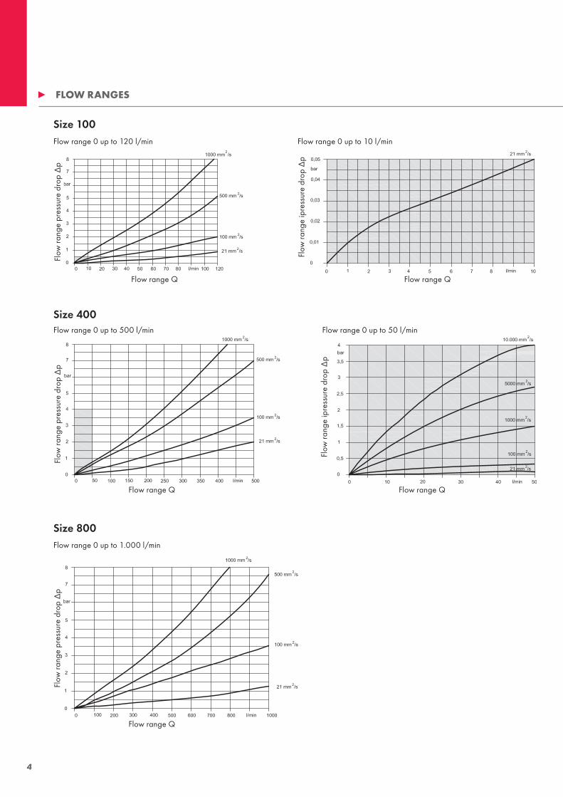
FlOw rangeS
Baugröße 100
Durchflussbereich 0 bis 120 l/min
Baugröße 400
Durchflussbereich 0 bis 500 l/min
Baugröße 800
Durchflussbereich 0 bis 1.000 l/min
Baugröße 100
Durchflussbereich 0 bis 10 l/min
Durchfluss Q Durchfluss Q
Dur
chflu
ssw
ider
stan
d ∆
p
Durchfluss Q
Dur
chflu
ssw
ider
stan
d ∆
p
Durchfluss Q
Dur
chflu
ssw
ider
stan
d ∆
p
Durchfluss Q
Dur
chflu
ssw
ider
stan
d ∆
p
Dur
chflu
ssw
ider
stan
d ∆
pBaugröße 100
Durchflussbereich 0 bis 50 l/min
Flow range 0 up to 120 l/min
Flow range Q Flow range Q
Flow range QFlow range Q
Flow range Q
Flow
rang
e pr
essu
re d
rop
∆p
Flow
rang
e ip
ress
ure
drop
∆p
Flow
rang
e ip
ress
ure
drop
∆p
Flow range 0 up to 500 l/min
Flow range 0 up to 1.000 l/min
Flow range 0 up to 50 l/min
Size 100
Size 400
Size 800
Flow range 0 up to 10 l/min
Flow
rang
e pr
essu
re d
rop
∆p
Flow
rang
e pr
essu
re d
rop
∆p
5
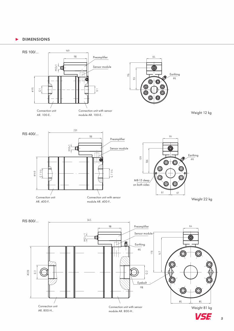
DiMenSiOnS
Preamplifier
Preamplifier
Preamplifier
Earthing
Earthing
Earthing
Eyebolt
on both sides M8-15 deep
Weight 12 kg
Weight 22 kg
Weight 81 kg
Sensor module
Sensor module
Sensor module
Connection unit with sensor module AR. 100-E..
Connection unit with sensor module AR. 400-F..
Connection unit with sensor module AR. 800-H..
Connection unitAR. 400-F..
Connection unitAR. 800-H..
Connection unit AR. 100-E..

6
TyPe cODe
Selectable interpolation factor
Pipeline connection
Ball bearingHard metal ball bearingAngular contact ball bearing
Modification figurefactory-provided
Without connection for PT 100
Without test port
Sensor module GSM 01
Modification figurefactory-provided
Flow Sensor
Connection unit Example
Spec
ial d
esig
n
stainless steel 1.4305 (V2A)
stainless steel 1.4571 (V4A)
Size
Inte
rpol
atio
n
Mat
eria
l
Mat
eria
l
Con
nect
ion
unit
Con
nect
ion
type
Fact
ory-
prov
ided
Bear
ing
Back
lash
Seal
ing
type
Con
struc
- tio
n ra
nge
Con
struc
tion
rang
e
Con
nect
ion
for
tem
pera
ture
sen
sor
Test
por
t
Sens
or m
odul
e
Seal
ing
type
Con
nect
ion
Size
stainless steel 1.4305 (V2A)stainless steel 1.4571 (V4A)

7
SenSOr MODule
A special sensor system detects any movement of the pair of rotors or of the liquid column. For this purpose, a precision gear connected to a shaft of the rotor pair is scanned by a special magnetoresistive sensor. The scanning sensor inclu-des two GMR-bridges (sin/cos) and is housed in a remo-vable stainless steel cartridge case together with a signal conditioning and amplifier unit. The downstream electronics unit features a high-resolution sin/cos-interpolator, which is
RS 100Max. permissible flow 126 l/min (n = 8025.2 rev/min)Min. permissible flow 0.25 l/min (n = 15.9 rev/min)
• Adjustable interpolation factors IPF: 1, 2, 5, 10, 25, 32, 50, 64, 100, 128 • Adjustable pulse filtering: up to 22% of the rotation volume• Adjustable preferential direction for filtering processes• Generating frequencies up to 100,000 Hz• Output of a separate directional signal or error signal (selectable)
adjustable with 10 different resolution factors. Furthermore, a programmable signal filter is available as well, which can offset unwanted negative pulse sequences up to an adju-stable degree. In addition, a signal for a separate direction detection, e.g. in case of a 1-channel evaluation, is provided by the electronics. Optionally, this output can be used for the detection of excess flows and temperatures.
• Automatic offset adjustment of the GMR-sensor-bridge (sinus, cosine) • Detection of stalled sensor or sensor faults/ magnet wheel damages• Flow overload detection with logging• Excess temperature detection with logging• Detection of exceeding the max. permissible highest frequency (> 100,000 Hz)• Readable error code LEDs
SenSOr elecTrOnicS DeScriPTiOn
FeaTureS
Technical DaTa
RS100
0
10
20
30
40
50
60
70
80
90
100
110
120
10 100 1.000 10.000 100.000
f[Hz]
Q[l/min]IP F=1 2 5 10 25
32
50
64
100
128
FLOW vs FREQuENCy

8
RS 400Max. permissible flow 525 l/min (n = 6,196.4 rev/min)Min. permissible flow 0.5 l/min (n = 5.9 rev/min)
RS 800Max. permissible flow 1,050 l/min (n = 3,888.9 rev/min)Min. permissible flow 5 l/min (n = 18.5 rev/min)
RS400
020406080
100120140160180200220240260280300320340360380400420440460480500520
10 100 1.000 10.000 100.000
f[Hz]
Q[l/min]IP F=1 2 5 10 25 32
50
64
100
128
RS800
0
50
100
150
200
250
300
350
400
450
500
550
600
650
700
750
800
850
900
950
1000
1050
10 100 1.000 10.000 100.000
f[Hz]
Q[l/min]IP F1 2 5 10 25 32 50
64
100
128
FLOW vs FREQuENCy
FLOW vs FREQuENCy

9
Oscillations in fluid systems manifest themselves through constant forward and backward movements of the liquid column, which is also detected by the rotor sensors and converted into proportional electronic pulses or edge sequences. These generated pulses can be incorrectly interpreted by the downstream evaluating unit or controller, which can be very distracting for the respective operating process.
The signal filtering function of the internal electronics con-tinuously offsets these generated edges during the rapid forward and backward movements of the rotor measuring element. The signals at the channel outputs are also sup-pressed until the internal offset is equalized or the initial position of the rotor measuring element has been reached again.
The user is able to set the degree of filtering in the form of partial volumes using rotary coding switches.
PulSe FilTering PrinciPle SuPPreSSeD vOluMe wiTh PulSe FilTering acTivaTiOn [ml]
2 4 6 8 10 12 1416 18 20 22 24 26 28 30 32 135791113151719212325272931
1 3 5 7 9 11 13 1517 19 21 23 25 27 29 31 24681012141618202224262830 0
Vorzugsrichtung Entgegengesetzte Richtung Vorzugsrichtung
Q
U
t
t
Signalausgabe mit Filterung
Signalausgabe ohne Filterung1
2
1
2
Filteraktivierung Filterdeaktivierung
Filter position rS 100X rS 400X rS 800X
0 0 0 0
1 0.145375 0.7845 2.5
2 0.29075 1.569 5.0
3 0.436125 2.3535 7.5
4 0.5815 3.138 10.0
5 0.726875 3.9225 12.5
6 0.87225 4.707 15.0
7 1.017625 5.4915 17.5
8 1.163 6.276 20.0
9 1.308375 7.0605 22.5
10 1.45375 7.845 25.0
11 1.599125 8.6295 27.5
12 1.7445 9.414 30.0
13 1.889875 10.1985 32.5
14 2.03525 10.983 35.0
15 2.180625 11.7675 37.5
Pulse filtering chart
Signal output without filtering
Filtering activation Filtering deactivation
Preferred directionOpposite directionPreferred direction
Signal output with filtering

10
elecTrical DaTa
The current publication of this catalogue supersedes all informa-tion from previous publications. VSE reserves the right to make changes and substitutions. VSE is not liable for any printing errors. Reproduction, including excerpts, is permitted only after written approval by VSE. Last revised: 01/2011
POwer SuPPly
Supply voltage u = 10 … 28 VDC; reverse pole protection
Current consumption I0 = 65 mA (at 24 VDC); unloaded
Delay tV = 8 µs max. (between scanning and measured value)
Signal OuTPuTS
Output signal shape Quadrature signals (A, B with 90° phase shift)
Directional output Positive high (24 V); negative low (0.8 – 1 V)
Error output Active high (24 V); inactive low (0.8 – 1 V)
Max. output frequency 100 kHz
Signal voltage output VSS = 9 … 27 VDC(channel 1, channel 2, direc/err)
Signal output current IOuT = 300 mA max. at 24 VDC(channel 1, channel 2)
Output final stages Push-pull-final stages, current-limited, short-circuit proof, internal cable adjustment, small saturation voltage, thermal shutdown with hysteresis, high-impedance outputs in case of error
11
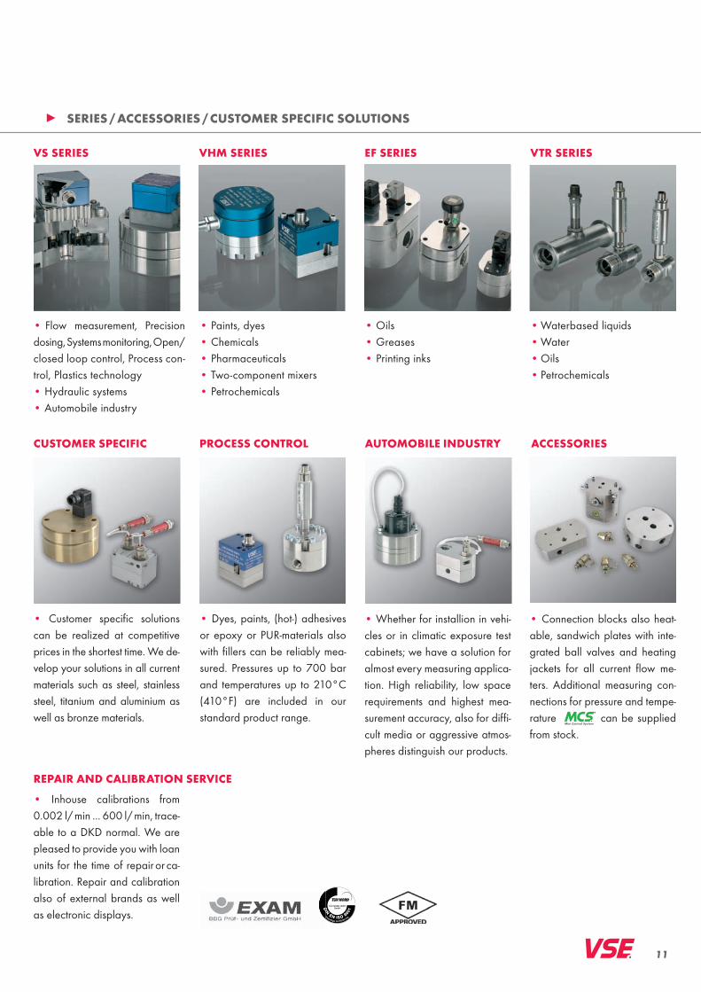
• Flow measurement, Precision dosing, Systems monitoring, Open/closed loop control, Process con-trol, Plastics technology • Hydraulic systems• Automobile industry
• Paints, dyes• Chemicals• Pharmaceuticals• Two-component mixers• Petrochemicals
• Oils• Greases• Printing inks
• Waterbased liquids• Water• Oils• Petrochemicals
• Inhouse calibrations from 0.002 l/ min ... 600 l/ min, trace-able to a DKD normal. We are pleased to provide you with loan units for the time of repair or ca-libration. Repair and calibration also of external brands as well as electronic displays.
• Customer specific solutions can be realized at competitive prices in the shortest time. We de-velop your solutions in all current materials such as steel, stainless steel, titanium and aluminium as well as bronze materials.
• Whether for installion in vehi-cles or in climatic exposure test cabinets; we have a solution for almost every measuring applica-tion. High reliability, low space requirements and highest mea-surement accuracy, also for diffi-cult media or aggressive atmos-pheres distinguish our products.
• Dyes, paints, (hot-) adhesives or epoxy or PuR-materials also with fillers can be reliably mea-sured. Pressures up to 700 bar and temperatures up to 210°C (410°F) are included in our standard product range.
cuSTOMer SPeciFic PrOceSS cOnTrOl auTOMOBile inDuSTry
• Connection blocks also heat-able, sandwich plates with inte-grated ball valves and heating jackets for all current flow me-ters. Additional measuring con-nections for pressure and tempe-rature can be supplied from stock.
acceSSOrieS
rePair anD caliBraTiOn Service
vS SerieS vhM SerieS eF SerieS vTr SerieS
SerieS / acceSSOrieS / cuSTOMer SPeciFic SOluTiOnS

12
wOrlDwiDe ServiceQualified advice through long-standing cooperation partners and own distribution companies_ personal _ competent_ efficient
VSE Volumentechnik GmbH VSE Volumentechnik GmbHHönnestraße 49 Postfach/P.O.Box 122958809 Neuenrade / Germany 58804 Neuenrade / Germany
Phone +49 (0) 23 94 / 6 16-30 info@vse-fl ow.com Fax +49 (0) 23 94 / 6 16-33 www.vse-fl ow.com
distributed by
01/1
1 w
ww
.pla
kart.
de
ArgentinaAustraliaAustriaBelgiumBrasilCanadachina*Czech RepublicDenmarkFinlandFrance*great Britain*Hungaryindia*IndonesiaIranIsraelitaly*Japan
DiSTriBuTOrS
www.e-holding.de
*own distribution companies
KuwaitMalaysiaMexicoThe NetherlandsNorwayPhilippinesPolandRussiaSingaporeSlovak RepublicSpainSouth AfricaSouth CoreaSwedenSwitzerlandThailandTurkeyuSa*Vietnam