flow past rotating cylinders at high reynolds … · flow past rotating cylinders at high reynolds...
TRANSCRIPT

FLOW PAST ROTATING CYLINDERS AT HIGH
REYNOLDS NUMBERS USING HIGHER ORDER UPWIND
SCHEME
MANOJ T. NAIR, TAPAN K. SENGUPTA{ andUMENDRA S. CHAUHAN
Department of Aerospace Engineering, Indian Institute of Technology, Kanpur 208 016, India
(Received 5 December 1996; in revised form 24 December 1997)
AbstractÐFlow past a translating and spinning circular cylinder at di�erent Reynolds numbers anddi�erent rotation rates is studied by solving the incompressible two-dimensional Navier±Stokesequation using a third-order upwind scheme. A detailed error analysis is made before choosing a gridthat minimises numerical dispersion and dissipation which are known to a�ect the higher orderschemes. The resultant grid-independent method is not restricted by numerical instability at high Rey-nolds numbers. The results are compared with the available experiments to establish the e�ectiveness ofthe scheme in solving high Reynolds number problem at di�erent rotation rates. This ®nite-di�erencemethod is found to be accurate and fast as compared with other published results. A speci®c case forRe = 3800 and O= 2.0 is investigated next. The pressure solution for this case is obtained by solvingthe pressure Poisson equation. # 1998 Elsevier Science Ltd. All rights reserved
1 . INTRODUCTION
The possibility of generating a transverse force by imparting rotation and hence circulationaround a body has been of interest for more than a century. In the literature, this is referred toas the Magnus e�ect after the discoverer of this e�ect (Batchelor [1] and Prandtl and Tietjens[2]). Unfortunately the increase of lift is associated with a high drag penalty thus producing littleaerodynamic e�ciency and hence has not been favoured in practical devices. However, it hasalso been shown by Prandtl that the e�ect of rotation has the bene®cial e�ect of inhibitingboundary layer separation and of suppressing it completely at su�ciently high rotational rates.The dual bene®t of inhibiting separation and at the same time producing high lift has promptedmany researchers (Tennant et al. [3] and Modi et al. [4]) to suggest the use of a rotating cylinderas boundary layer control device on the ¯aps of V/STOL aircrafts, upstream of the ship rudderand in sub-sonic di�users. Consequently understanding the nature of such ¯ows and in particu-lar to ascertain the level of rotation to delay separation is of utmost importance.
The two-dimensional ¯ow ®eld generated by an in®nitely long circular cylinder of diameter Dtranslating with an uniform velocity U1 at right angles to its axis and rotating about this axiswith constant angular velocity O* has been studied. The cylinder attains its rotational and trans-lational speeds impulsively. The two important parameters of this study are the Reynolds num-ber given by Re = U1D/n, with n as the coe�cient of kinematic viscosity and the ratio ofperipheral to translational speed O= O*D/2U1.
In the early attempts, the Magnus e�ect had been explained by inviscid theory (Batchelor [1])and the resultant lift was found to be proportional to the rotation rate. This is not the case forreal ¯uids with boundary layer separation. It is to be pointed out that for moderate-to-highReynolds number ¯ows the surface roughness and other three-dimensional e�ects play a signi®-cant part. However, it is beyond the scope of the present day computers and attention isfocussed on two-dimensional ¯ows. In the present paper, results are obtained numerically andcompared with the experimental results of Coutanceau and Menard [5] who have stated that
Computers & Fluids Vol. 27, No. 1, pp. 47±70, 1998# 1998 Elsevier Science Ltd. All rights reserved
Printed in Great Britain0045-7930/98 $19.00+0.00PII: S0045-7930(97)00031-5
{Corresponding author.
47

their experimental results exhibited two-dimensional ¯ow ®eld. Diaz et al. [6], in presenting their
measured velocity ®eld at Re = 9000, have stated that the measured ¯ow quantities did not
exhibit three-dimensionality. However, we have not computed this ¯ow ®eld as at this higher
Reynolds number the ¯ow is turbulent in the near wake.
For the two-dimensional ¯ow ®eld, Glauert [7] considered the development of steady ¯ow for
high Reynolds number for both large and small values of rotation rates on the basis of bound-
ary layer theory. Similar studies were undertaken by Wood [8] and Moore [9]; all of which
showed that lift increases linearly with rotation rate. Some of the early computations of the
Navier±Stokes equations were restricted to low Reynolds numbers, where the ¯ow ®eld remains
steady. This restriction on Reynolds numbers is due to poor convergence rate and other numeri-
cal stability problems. These results are due to Townsend [10], Ingham and Tang [11] and Tang
and Ingham [12].
The unsteady ¯ow development at low rotation rate is of interest because of its importance in
understanding ¯ow separation. The ®rst meaningful computation of such a ¯ow ®eld is due to
Badr and Dennis [13] from the numerical solution of the two-dimensional Navier±Stokes
equation. The results reported were for Re = 200 and 500 and rotation rates of 0.5 and 1.0. In
Badr et al. [14], the developed numerical method was extended to Re = 10 000 and rotation rate
to 3.25 and compared with experimental results due to Coutanceau and Menard [5]. The method
is based on a hybrid spectral±®nite di�erence formulation of Navier±Stokes equation in bound-
ary layer coordinate system that changes with time. The starting solution was obtained by using
a formal perturbation technique with time as the small parameter. However, the equation giving
the initial wall vorticity is reported incorrectlyÐthe correct expression appears in Chew et al.
[15], Kimura et al. [16] have studied the problem of rotating and translating cylinder by discrete
vortex method. The reported results have a limited applicability as there were only 14 surface
segments on the cylinder. Chen et al. [17] have produced results using a ®nite-di�erence±pseudo-
spectral method for solving the Navier±Stokes equation. Although the results are of good qual-
ity, results have only been obtained for Re = 200 for various rotation rates. The emphasis of
the paper was to show that vortices continue to shed when viewed from a reference frame mov-
ing with a vortex.
One of the earliest experimental results for the nominally two-dimensional ¯ow past a trans-
lating and rotating circular cylinder can be seen in Prandtl and Tietjens [2]. The other ¯ow visu-
alization results are due to Taneda [18,19] and Koromilas and Telionis [20]. In Coutanceau and
Menard [5], ¯ow visualization results are presented for di�erent Reynolds numbers and rotation
rates at di�erent time instants that could be used for qualitative comparison with computations.
The Reynolds number at which experiments were performed were 200, 500 and 1000, while the
rotation rate varied from 0.28 to 3.25 with most of the results for Re = 200. Diaz et al. [6] con-
ducted an experimental investigation at Re = 9000, where near-wake velocities were measured
by a hot wire probe. The reported results for rotating cylinder showed the measured Reynolds
stress near the midplane of the wake to be much lower when the rotation rate increases as com-
pared with the Reynolds stress for a translating cylinder.
The numerical method used for the present exercise has earlier been used in Sengupta and
Sengupta [21] for ¯ow past a translating cylinder at high Reynolds numbers. When the same
method was used for the rotating cylinder case, it exhibited some convergence and grid depen-
dence problems. In the present exercise, we have used a much stricter convergence criteria for
the solution of the boundary value problem. In general, higher-order schemes su�er from a grid
dependence of the obtained solution. In this paper, we have analysed this and developed a new
strategy for avoiding grid dependence. The results are presented for the cases shown in Fig. 1.
Some of the results are compared with other computational and experimental results reported in
Coutanceau and Menard [5] and Badr et al. [14]. Additional results are presented for Re = 3800
and O= 2.0.
In Section 2, the governing equations and associated boundary conditions are discussed. In
Section 3, the numerical method is presented, and ®nally in Section 4, the results and discussion
are given.
M. T. Nair et al.48

2. GOVERNING EQUATIONS AND BOUNDARY CONDITIONS
The unsteady Navier±Stokes equation for incompressible two-dimensional ¯ows are solvedhere in stream function and vorticity formulation and are given by:
r2c � ÿo �1�and
@o@ t� r � �oV� � 1
Rer2o �2�
where o is the vorticity de®ned by
o � �r � V� � k �3�and the velocity is related to the stream function by
V � r �CCC �4�where CC = (0, 0, c).
Fig. 1. Schematic of ¯ow around a translating and rotating circular cylinder; the table gives parametercombinations computed. Re is the Reynolds number and O is the non-dimensional rotation rate.
Flow past rotating cylinders 49

The computations are performed in the translational frame in an O-grid topology. The trans-formed coordinates are related to the physical coordinates by:
x � r�Z� cos�2px�
y � r�Z� sin�2px� �5�where x and Z are the normalized transformed coordinates along the circumference and radius,respectively.
The grids are uniformly spaced in the x-direction, while the radial spacing is chosen such thatthe grid related dispersion and dissipation errors are minimum and is given by:
r�Z� � r0 � ZDZ
�Dr0 � d
2
�ZDZÿ 1
���6�
where r0 indicates the radius of the cylinder, Dr0 is the spacing of the ®rst radial grid line and dis the increment of the successive grid line spacing. This particular choice of grid removes altera-tion of basic convection and lowest order dissipation. The rational is discussed in Section 3 fol-lowing Equation (17). The other details of the formulations are the same as in Sengupta andSengupta [21]. The steady-state inviscid solution is taken to be the initial condition for theimpulsively started cylinder problem.
The governing Poisson equation for pressure is obtained by taking the divergence of theNavier±Stokes equation in primitive variables. For an orthogonal curvilinear coordinate systemthis is given as:
@
@x
�h2h1
@p
@x
�� @
@Z
�h1h2
@p
@Z
�� @
@x�h2vo � ÿ @
@Z�h1uo � �7�
For the boundary conditions on the cylinder wall, the no-slip condition is used and is given by:
@c@Z
����body
� h2r0O �8�
and
c � constant �9�where h1 and h2 are the scale factor (de®ned in Section 3).While Equations (8) and (9) are used in calculating the wall vorticity, Equation (9) is used
only in solving the stream function Equation (1). The additional periodic boundary conditionsis applied at the cut (see de®nition in Fig. 1), while at the outer boundary uniform ¯ow con-ditions are applied. The corresponding far ®eld boundary conditions are either:
@o@Z� 0 �10�
or
@ 2o@Z2� 0: �11�
Most of the results presented in this paper are from using the boundary condition given inEquation (10).
For the pressure Poisson equation [Equation (7)] the Neumann boundary condition, asobtained from the normal (Z) momentum equation, is used on the surface and outer boundary,whereas periodic boundary condition is applied at the cut (Fig. 1).
3 . NUMERICAL METHOD
The stream function equation Equation (1), is retained in the following self-adjoint formwhile solving it numerically in the transformed plane,
M. T. Nair et al.50
@
@x
�h2h1
@c@x
�� @
@Z
�h1h2
@c@Z
�� ÿh1h2o �12�
where h1 and h2 are the scale factors of the transformation given by
h1 �����������������x2x � y2x
qh2 �
����������������x2Z � y2Z
qThe vorticity transport equation when written in the transformed plane is given by:
h1h2@o@ t� h2u
@o@x� h1v
@o@Z� 1
Re
�@
@x
�h2h1
@o@x
�� @
@Z
�h1h2
@o@Z
���13�
where the components of the velocity vector are given by
h2u � @c@Z
h1v � ÿ @c@x: �14�
These equations and their solution method has been described in details in Sengupta and
Sengupta [21] and are quoted here in brief. The ®nite-di�erence form of various derivatives in
Equations (12) and (13) are obtained by employing central di�erencing, excepting the convection
terms in Equation (13), which are discretized using a third-order upwind scheme [22] given by:�o@o@Z
�i
� uiÿui�2 � 8
ÿui�1 ÿ uiÿ1
�� uiÿ212Z
� juij ui�2 ÿ 4ui�1 � 6ui ÿ 4uiÿ1 � uiÿ24Z
: �15�
The reader is referred to Appendix A of Sengupta and Sengupta [21] for a detailed analysis of
the various ®nite-di�erence schemes. The upwinding produces a truncation error proportional to
the fourth derivative of the vorticity with respect to the transformed variable. These error terms
when projected back in the physical plane give rise to numerical dispersion, added dissipation
and altered convection, which produce grid-dependent results. In the present work, the particu-
lar choice of the grids as given by Equations (5) and (6) minimizes dispersion and dissipation
but does not alter the convection terms at all. Discretizing the convection term h1v�@o=@Z� bythe third-order upwinding results in a truncation error:
DZ3
4�h1v� @
4o@Z4
: �16�
This scheme was originally proposed by Kawamura et al. [22] where the authors stated that the
truncation error is a higher-order dissipation term which stabilizes computations at high
Reynolds numbers and does not a�ect the physical dissipation. This is true only when one
works in the physical plane. Working on a general transformed plane, Equation (16) can be
rewritten in the physical cartesian plane as:
� h1vDZ3
4fA� B� C �D� E � F � G g �17�
where the quantities in the parenthesis are given by
A � @4x
@Z4@o@x� @
4y
@Z4@o@y
Flow past rotating cylinders 51

B ��3
�@2x
@Z2
�2
� 4@x
@Z@3x
@Z3
�@2o@x2��3
�@2y
@Z2
�2
� 4@y
@Z@3y
@Z3
�@2o@y2
C ��4@x
@Z@3y
@Z3� 6
@2x
@Z2@2y
@Z2� 4
@y
@Z@3x
@Z3
�@2o@x@y
D � 6
�@x
@Z
�2 @2x
@Z2@3o@x3� 6
�@y
@Z
�2 @2y
@Z2@3o@y3
E � 6
��@x
@Z
�2 @2y
@Z2� 2
@x
@Z@y
@Z@2x
@Z2
�@3o@x2@y
�6��@y
@Z
�2 @ 2x
@Z2� 2
@x
@Z@y
@Z@2y
@Z2
�@3o@x@y2
F ��@x
@Z
�4 @4o@x4��@y
@Z
�4 @4o@y4
G � 4
�@x
@Z
�2 @y
@Z@4o@x3@y
� 6
�@x
@Z@y
@Z
�2 @4o@x2@y2
� 4@x
@Z
�@y
@Z
�2 @4o@x@y3
:
A similar set of terms will be obtained for the truncation error terms associated with the otherconvection term. It is easy to see that because of the large ¯ow gradients in the normal directionclose to the body, only the truncation error terms as given in Equation (16) will be dominant.In Equation (17), the term A represents alteration in physical convection. The terms B, D and Frepresent pure dissipation, dispersion and higher-order dissipation, respectively. While the termsC and G gives rise to mixed dissipation, the term E represents mixed dispersion. These trunca-tion error terms alter the quality of the solution if proper care is not exercised. It is to be notedthat if one chooses the constant radial lines to be stretched in a geometric progression, as isusually performed in boundary layer analyses, then all the components of the truncation errorwill be present. This type of stretching was used in Sengupta and Sengupta [21]. The grid trans-formation given by Equations (5) and (6) does not alter the pure convection via the term A. Ina similar way the second-order dissipation (both pure and mixed) will be greatly reduced whichare due to @3x=@Z3 and @ 3y=@Z3 in B and C. In addition, it is easy to see that the coe�cients ofthe dispersion terms (D and E) are three to four orders of magnitude smaller.
Flows past a rotating cylinder is a perfect case for studying the receptivity of blu� body ¯owsas compared with the non-rotating cylinder case. Computationally, the translating cylindereither does not exhibit vortex shedding (Braza et al. [23]) or it shows asymmetry much later ascompared with experiments (Nair and Sengupta [24]). One of the reasons cited for such a beha-viour is the inability to prescribe the disturbance environment completely. For the rotatingcylinder in uniform ¯ow the rotational e�ects would dominate the background inherent disturb-ance ®eld. Furthermore the results at Re = 200 and 1000 seem to be insensitive to initial con-ditions. As pointed out earlier, Badr and Dennis [13] have not used the correct expression forthe initial wall vorticity, but showed good agreement with the experimental results. In the pre-sent e�ort the initial wall vorticity is calculated by discretizing the stream function equationwhile satisfying the no-slip condition.
We would also like to comment on the convergence criteria that is often used in iterative sol-vers for elliptic equations. It has been noted by Roach [25] and Ferziger [26] that comparingsuccessive iterates to check for convergence lead to erroneous results. Instead one can use thesolution residue for checking the convergence. In this work, the solution residue at every gridpoint is made to fall below a preassigned value (0.00001). This method of checking convergenceat every point is a stronger method than what is often used in other methods (see, for example,
M. T. Nair et al.52

Mittal and Tezduyar [27]) where an average over the whole ¯ow domain is computed and com-pared for convergence at each level of iteration.
For the solution of the Poisson equations [Equations (12) and (7)], the alternating directionimplicit (ADI) method of Peaceman and Rachford (as given in Ames [28]) and the modi®edstrongly implicit procedure (MSIP) of Schneider and Zedan [29] are used. In general, theequations are discretized at the cell nodes while the pressure equation is discretized at the cellcentres for the boundary points. The time discretization for Equation (13) is by two point Eulerbackward scheme.
4 . RESULTS AND DISCUSSION
The computations are performed on a O-type grid with 251 points in the azimuthal and 300points in the radial direction for Re = 200 and 1000 cases. A ®ner grid with 400 points in theradial direction has been used for the case of Re = 3800. Time integration is performed byEuler backward two point discretization with a time step of 0.0001. The ®rst azimuthal line is0.001 distance away from the cylinder. The outer boundary is located 12 diameters from thecylinder (as used in Chen et al. [17]). The present grids are ®ner compared with the (128� 120)grid used by Chen et al. [17]. Badr and Dennis [13] and Badr et al. [14] took a value of Dz of0.05 in initial stages and 0.1 beyond t = 1.5, where z is the radial distance non-dimensionalizedby viscous length scale (usually de®ned for unsteady boundary viscous ¯ows). Because they useda ®xed maximum value of z (a quantity which varies as tÿ0.5), the grid resolution in the physicalspace becomes inferior as time progresses. Furthermore, the use of central di�erencing with ex-ponentially stretched grid will have larger spurious dispersion, as discussed in Section 3. Thehigher-order spatial accuracy of the present scheme allows resolving high wavenumber com-ponents of the solution. A constant time step of 0.0001 is used here as compared with the vari-able time steps taken by Chen et al. [17] (between 0.0001 and 0.01) and Badr and Dennis [13](between 0.05 and 0.1).
The results reported here are for the cases shown in Fig. 1. It was conjectured by Chen et al.[17] that the ¯ow will be predominantly unsteady and two-dimensional for high Reynolds num-bers (greater than 50) and small rotation rates. For the Re = 200 case, the ¯ow will be unsteadyand the corresponding results are shown in Figs 2 and 3. The qualitative agreement of the com-puted results with the experimental results of Coutanceau and Menard [5] and the computedresults of Badr et al. [14] and Chen et al. [17] is excellent.
For the reported computations for Re = 1000, the Poisson equation for the stream functionrequired three ADI cycles involving three acceleration parameters. The computing time requiredfor each time step is roughly 5 s on an HP 735/100 workstation for the case of Re = 1000 andO = 3.0. This ®gure is one-third for the lower Reynolds number and lower rotation rate cases.This time compares very favourably with the reported computation time of 5 CPU seconds pertime step on a CRAY 2 in Chen et al. [17] for the case of Re = 200 and O= 0.5 and 1.0,although the present computations were performed on a (251�300) grid as compared with(128� 120) grid used by Chen et al. The main aim of the present paper is to demonstrate theability of the present numerical method to produce very accurate results with very little compu-tational e�orts. As discussed earlier the accuracy of the solution is due to:
1. higher-order spatial accuracy of the scheme;2. choice of the grid along the radial direction [Equation (6)];3. very ®ne mesh that has been used;4. very ®ne time step.
The initial ¯ow ®eld for the present computation for the impulsively started rotation andtranslation is given by the potential ¯ow. Detailed perturbation results have been produced byBadr et al. [14] and Chew et al. [15] for initial solution of Navier±Stokes equation which theyhave used for starting their computations. This is performed following the procedure originallygiven in Collins and Dennis [30]. Few comments are in order here on the initial condition.Although most of the computations reported for the rotating cylinder cases use impulsivelystarted condition, the corresponding laboratory experiments reveal some di�erences. For the ex-perimental set-up described by Coutanceau and Menard [5], it is easy to see that the character-
Flow past rotating cylinders 53

Fig. 2(a±d)ÐCaption on page 10.
M. T. Nair et al.54

Fig. 2(e±h)ÐCaption overleaf.
Flow past rotating cylinders 55

Fig. 2. Comparison of experimental [5] and computational streamlines for ¯ow past a translating androtating circular cylinder at Re= 200 and O= 0.5 .
M. T. Nair et al.56

Fig. 3(a±d)ÐCaption overleaf.
Flow past rotating cylinders 57

istic time scale evaluated from the free stream speed and the diameter of the cylinder rangesbetween 0.8 and 12 s for the chosen translational velocities (0.5±5 cm/s) and diameter of thecylinders (4 or 6 cm). Comparing this time with the tunnel start up time of about 0.1 s, theassumption of impulsive start seems quite adequate for the present computations. The plottedstreamlines are in the same frame of reference as in the experiment, i.e. the visualization is in atranslating frame of reference.
Figure 2(a±j) shows the comparison of experimental results of Coutanceau and Menard[5] with our computation for Re = 200 and O= 0.5 for di�erent times. The time scaleadopted in the present computations are same as that in Coutanceau and Menard [5],while the results reported in Badr et al. [14] requires a division by two of the correspond-ing times therein.
Fig. 3. Comparison of experimental [5] and computational streamlines for ¯ow past a translating androtating circular cylinder at Re= 200 and O= 1.0.
M. T. Nair et al.58

There is an excellent account of the ¯ow topology and speci®cally the separation pattern andvortex shedding from a spinning cylinder in Coutanceau and Menard [5]. It is pointed out inCoutanceau and Menard [5] that the saddle points for the cases of a rotating cylinder will be or-thogonal which can also be ascertained from the ®gures. Furthermore, it is stated that the lossof symmetry due to rotation will lead to the disappearance of eddies forming on the lower sideof the cylinder for an anticlockwise rotation. The presence of a thin rotating layer of ¯uid closeto the cylinder pushes the stagnation point from the cylinder as can be seen from the plottedstreamline patterns. The streamlines ABC [as in Fig. 2(f)] with the progress of time reveals thealleyway formation around the primary vortex.
Figure 3(a±g) shows the similar comparison between experimental visualization and computedstreamline for the case of Re = 200 and O= 1.0. Once again, our results are indistinguishablefrom the computations of Badr and Dennis [13] except for t = 3.0 where it is seen that neitherof the computations match with the experimental result to all details of the ¯ow ®eld. Thematch is, however, quite good at subsequent times. The solution changes in character at aroundthis time and the elliptic solver needs larger number of iterations for convergence. As comparedwith the case of O = 0.5, here the second and third vortices are released much later. The trans-positioning of saddle points and alleyway formation are absent here. The nascent second andthird vortices appear sometime between t = 4.0 and 4.5. In the next frame at t = 5.0, these twovortices merge to form a single recirculating zone. These can be seen better in the vorticity con-tours as plotted as a function of time in Fig. 4, which are also compared with the computationsof Chen et al. [17].
In Fig. 5, we show the computed streamline contours for the case of Re = 1000 and O= 3.0.These are also compared with experimental results and other computations wherever possible.Once again, the agreement is quite encouraging except for later times. While our calculationsmatch with the results of Badr et al. [14] for all times shown, both the calculations di�er fromthe corresponding experimental results for t = 3.0 and beyond. The larger time results showremarkable similarity with the steady-state inviscid results (as can be seen in Batchelor [1]) andthe experimental results reported in Prandtl and Tietjens [2]. Badr et al. [14] have stated that thelack of agreement is due to either three-dimensionality or the ¯ow becoming turbulent. In theabsence of any three-dimensional calculations, it is not possible to pinpoint the reasons.However, we would like to conjecture that this could also be due to vibration of the cylinderand other disturbance sources ingested from the shear layer on the wind tunnel wall at large ro-tation rates for high translational velocities of the towed model in the tunnel. This is plausiblesince the agreement becomes poor only close to the body; also, the presented results in Badr etal. [14] for Re = 1000 and O= 2.0 shows a very good agreement even for t = 6.5. It is knownfrom the experimental results of Diaz et al. [6] that the Reynolds stress reduces near the planeof symmetry in the wake signi®cantly with increase in rotation rate and hence the e�ect of tur-bulence will be more pronounced for O = 2.0 than for 3.0Ðwhich is at odds with the con-clusions of Badr et al. [14]. The present numerical scheme can resolve much higherwavenumbers for high Reynolds number ¯ows and this was the reason that the original propo-nents of this scheme [22] claimed that a direct numerical simulation (DNS) is possible with thismethod. However, without simulating the full three-dimensional ¯ows this cannot be tested forthe present ¯ow situation. This will be an attractive proposition for computing higher Reynoldsnumber ¯ows keeping in view the observation of Diaz et al. [6] for reducing Reynolds stressesand eventually relaminarizing the ¯ow.To investigate this issue further we have also computed the case for Re = 3800 and O= 2.0.
The results are presented in Fig. 6 and it is quite clear that even at t = 20, the ¯ow has notreached the steady-state. This case was computed as Tokumaru and Dimotakis [31] have pro-vided a lift value for this case. From Figure 3 of Tokumaru and Dimotakis [31], it is seen thatthe lift value for this rotation rate is insensitive to Reynolds number and the ratio of cylinderspan and diameter. The results for three di�erent rotation rate cases at Re = 3800 are providedin Mittal et al. [32].
Here the computed ¯ow ®eld reveals some interesting di�erences with the Re = 1000 andO = 3.0 case. We know from the potential ¯ow theory that a closed ring of ¯uid forms aroundthe cylinder for a rotation rate greater than 2.0; however, one can note the closed ring of ¯uid
Flow past rotating cylinders 59
forming for this case. This ring of ¯uid retains its identity and then again disappears because ofvarious vortex interactions. From Fig. 6, one can note the formation of such rings at t= 3.5,8.5 and 14.5 and which disintegrates at t = 5.0, 10.5 and 16.5, respectively. The present sets ofcomputations are performed only up to t= 20 and within this period, the ¯ow reveals somesort of periodicity. The important ¯ow features revealed through these computations are the fol-lowing: initially, one can notice the formation of a pair of vortices near the shoulder of thecylinder which continuously interact with each other. By t= 2.0, they merge with each other.
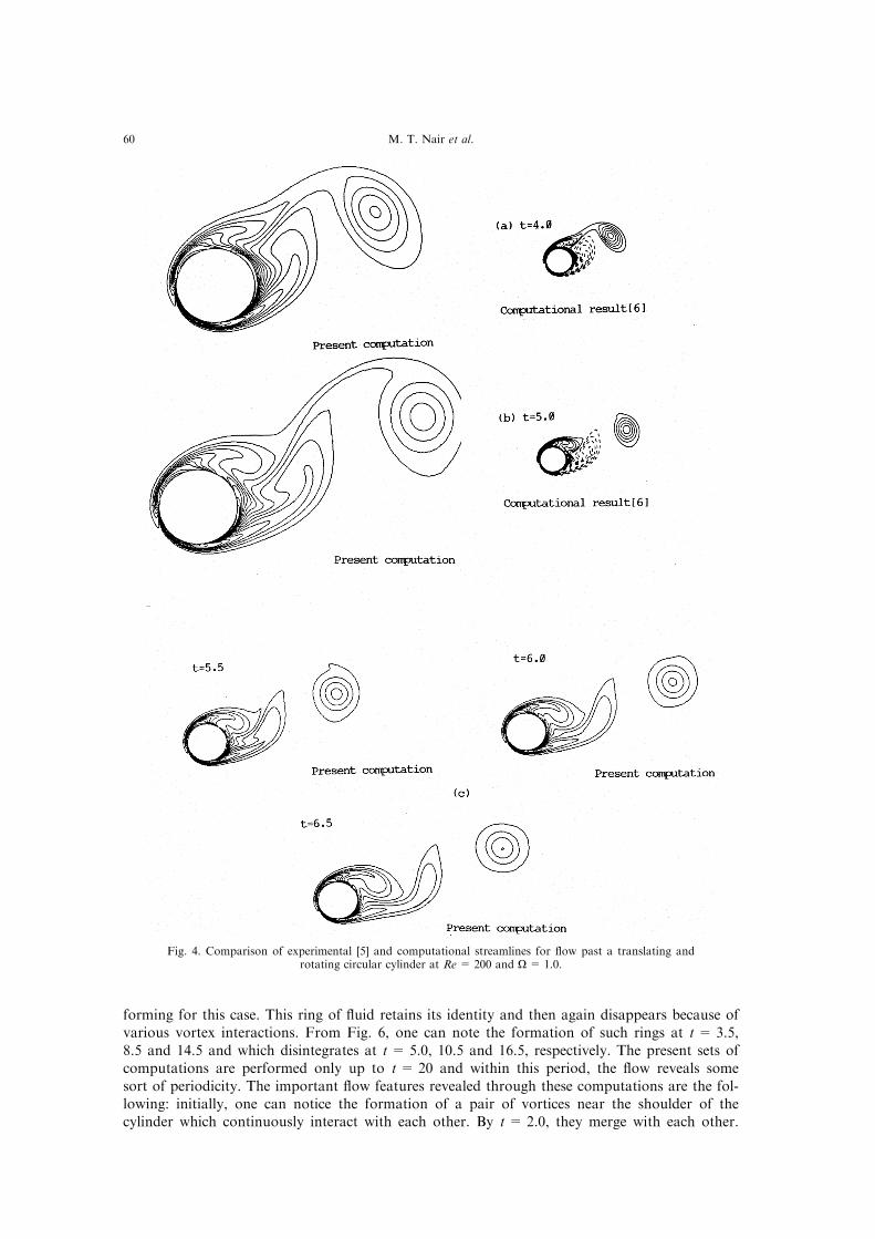
Fig. 4. Comparison of experimental [5] and computational streamlines for ¯ow past a translating androtating circular cylinder at Re= 200 and O= 1.0.
M. T. Nair et al.60

Fig. 5(a,b)ÐCaption on page 17.
Flow past rotating cylinders 61

Fig. 5(c±e)ÐCaption opposite.
M. T. Nair et al.62

Fig. 5. Comparison of experimental and computational [14] streamlines with the present computationsfor ¯ow past translating and rotating circular cylinder at Re = 1000 and O= 3.0.
Flow past rotating cylinders 63

Fig. 6(a).
M. T. Nair et al.64

Fig. 6. Streamline contours for ¯ow past a translating and rotating circular cylinder at Re= 3800 andO= 2.0 .
Flow past rotating cylinders 65
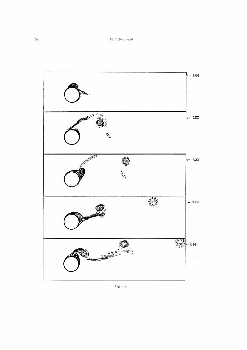
Fig. 7(a).
M. T. Nair et al.66

Fig. 7. Isovorticity contours for ¯ow past a translating and rotating circular cylinder at Re = 3800 andO= 2.0.
Flow past rotating cylinders 67
At t = 5.5, the closed ring of ¯uid disintegrates and the streamline coming from the top forms atongue-shaped recirculation zone and wraps around the cylinder like an alleyway. The aboverecirculation zone keeps growing in length and width with time, and at t = 8.5 it detaches fromthe body along with the formation of the closed ring of ¯uid close to the boundary. Notice thatthis ring also encompasses a small vortex and because of this the ring takes a distorted formÐwhich is never seen for the Re = 1000 and O= 3.0 cases. At t= 6.5, the above-mentionedrecirculation zone gives rise to a bubble near the shoulder of the cylinder and in the process thedividing streamline turns by 2708 and remains so until t = 8.0, after which this situation is notseen to recur. A similar sequence leading to formation of a tongue-like recirculation zone occursat t = 17.0 and this remains intact till the end of computation at t= 20. From the vorticitycontours shown in Fig. 7, one can discern a pattern of shed vortices after t = 10. One sees theformation of two anticlockwise vortex to a single clockwise vortex. While the anticlockwise vor-tices seem to form on the lower lee side of the cylinder, the clockwise vortices form in the vicin-ity of the shoulder of the cylinder.
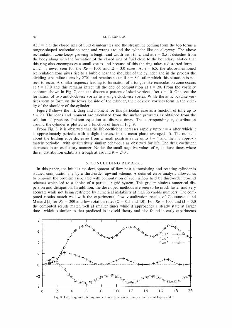
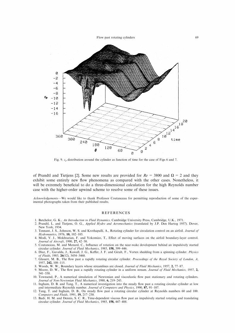
Figure 8 shows the lift, drag and moment for this particular case as a function of time up tot = 20. The loads and moment are calculated from the surface pressures as obtained from thesolution of pressure. Poisson equation at discrete times. The corresponding cp distributionaround the cylinder is plotted as a function of time in Fig. 9.
From Fig. 8, it is observed that the lift coe�cient increases rapidly upto t= 4 after which itis approximately periodic with a slight increase in the mean phase averaged lift. The momentabout the leading edge decreases from a small positive value upto t= 4 and then is approxi-mately periodicÐwith qualitatively similar behaviour as observed for lift. The drag coe�cientdecreases in an oscillatory manner. Notice the small negative values of cd at those times wherethe cp distribution exhibits a trough at around y = 2408.
5 . CONCLUDING REMARKS
In this paper, the initial time development of ¯ow past a translating and rotating cylinder isstudied computationally by a third-order upwind scheme. A detailed error analysis allowed usto pinpoint the problem associated with computation of such a ¯ow ®eld by third-order upwindschemes which led to a choice of a particular grid system. This grid minimizes numerical dis-persion and dissipation. In addition, the developed methods are seen to be much faster and veryaccurate while not being restricted by numerical instability at high Reynolds numbers. The com-puted results match well with the experimental ¯ow visualization results of Coutanceau andMenard [5] for Re = 200 and low rotation rates (O = 0.5 and 1.0). For Re = 1000 and O = 3.0the computed results match well at smaller times while it approaches a steady state at largertimeÐwhich is similar to that predicted in inviscid theory and also found in early experiments
Fig. 8. Lift, drag and pitching moment as a function of time for the case of Figs 6 and 7.
M. T. Nair et al.68
of Prandtl and Tietjens [2]. Some new results are provided for Re = 3800 and O = 2 and theyexhibit some entirely new ¯ow phenomena as compared with the other cases. Nonetheless, itwill be extremely bene®cial to do a three-dimensional calculation for the high Reynolds numbercase with the higher-order upwind scheme to resolve some of these issues.
AcknowledgementsÐWe would like to thank Professor Coutanceau for permitting reproduction of some of the exper-imental photographs taken from their published results.
REFERENCES
1. Batchelor, G. K., An Introduction to Fluid Dynamics. Cambridge University Press, Cambridge, U.K., 1971.2. Prandtl, L. and Tietjens, O. G., Applied Hydro and Aeromechanics (translated by J.P. Den Hartog 1957). Dover,
New York, 1934.3. Tennant, J. S., Johnson, W. S. and Krothapalli, A., Rotating cylinder for circulation control on an airfoil. Journal of
Hydronautics, 1976, 10, 102±105.4. Modi, V. J., Mokhtarian, F. and Yokomizo, T., E�ect of moving surfaces on the airfoil boundary-layer control.
Journal of Aircraft, 1990, 27, 42±50.5. Coutanceau, M. and Menard, C., In¯uence of rotation on the near-wake development behind an impulsively started
circular cylinder. Journal of Fluid Mechanics, 1985, 158, 399±446.6. Diaz, F., Gavalda, J., Kawall, J. G., Ke�er, J. F. and Giralt, F., Vortex shedding from a spinning cylinder. Physics
of Fluids, 1983, 26(12), 3454±3460.7. Glauert, M. B., The ¯ow past a rapidly rotating circular cylinder. Proceedings of the Royal Society of London, A,
1957, 242, 108±115.8. Woods, W. W., Boundary layers whose streamlines are closed. Journal of Fluid Mechanics, 1957, 2, 77±87.9. Moore, D. W., The ¯ow past a rapidly rotating cylinder in a uniform stream. Journal of Fluid Mechanics, 1957, 2,
541±550.10. Townsend, P., A numerical simulation of Newtonian and viscoelastic ¯ow past stationary and rotating cylinders.
Journal of Non-Newtonian Fluid Mechanics, 1980, 6, 219±243.11. Ingham, D. B. and Tang, T., A numerical investigation into the steady ¯ow past a rotating circular cylinder at low
and intermediate Reynolds number. Journal of Computers and Physics, 1990, 87, 91±107.12. Tang, T. and Ingham, D. B., On steady ¯ow past a rotating circular cylinder at Reynolds numbers 60 and 100.
Computers and Fluids, 1991, 19, 217±230.13. Badr, H. M. and Dennis, S. C. R., Time-dependent viscous ¯ow past an impulsively started rotating and translating
circular cylinder. Journal of Fluid Mechanics, 1985, 158, 447±488.
Fig. 9. cp distribution around the cylinder as function of time for the case of Figs 6 and 7.
Flow past rotating cylinders 69

14. Badr, H. M., Coutanceau, M., Dennis, S. C. R. and Menard, C., Unsteady ¯ow past a rotating circular cylinder atReynolds numbers 1000 and 10 000. Journal of Fluid Mechanics, 1990, 220, 459±484.
15. Chew, Y. T., Cheng, M. and Luo, S. C., A numerical study of ¯ow past a rotating circular cylinder using a hybridvortex scheme. Journal of Fluid Mechanics, 1995, 299, 35±71.
16. Kimura, T., Tsutahra, M. and Wang, Z., Wake of a rotating circular cylinder. AIAA Journal, 1992, 30, 555±556.17. Ou, Y. R., Chen, Y. M. and Pearlstein, A. J., Development of the wake behind a circular cylinder impulsively
started into rotatory and rectilinear motion. Journal of Fluid Mechanics, 1993, 253, 449±484.18. Taneda, S., Visual study of unsteady separated ¯ows around bodies. Progress in Aeronautical Science, 1977, 17, 287±
347.19. Taneda, S., Visual observations of the ¯ow past a circular cylinder performing a rotatory oscillation. Journal of the
Physical Society of Japan, 1978, 45, 1038±1043.20. Koromilas, C. A. and Telionis, D. P., Unsteady laminar separation: an experimental study. Journal of Fluid
Mechanics, 1980, 97, 347±384.21. Sengupta, T. K. and Sengupta, R., Flow past an impulsively started circular cylinder at high Reynolds number.
Research Journal into Compuational Mechanics, 1994, 14(4), 298±310.22. Kawamura, T., Takami, H. and Kuwahara, K., A new higher order upwind scheme for incompressible Navier±
Stokes equation. Fluid Dynamics Research, 1985, 1, 145±162.23. Braza, M., Chassaing, P. and Ha Minh, H., Numerical study and physical analysis of the pressure and velocity ®elds
in the near wake of a circular cylinder. Journal of Fluid Mechanics, 1986, 165, 79±130.24. Nair, M. T. and Sengupta, T. K., Onset of asymmetry: ¯ow past circular and elliptic cylinders. International Journal
of Numerical Methods in Fluids, 1996, 23, 1327±1345.25. Roach, P. J., A method for uniform reporting of grid re®nement studies. Symposium on Uncertainty in
Computational Fluid Dynamics. ASME Fluids Engineering Division, Summer Meeting, Washington, DC, 1993.26. Ferziger, J. H., Estimation and reduction of numerical error. Paper presented at the Symposium on Quanti®cation
of Uncertainty in Computational Dynamics, ASME Fluids Engineering Division, Summer Meeting, WashingtonDC, 1993.
27. Mittal, S. and Tezduyar, T. E., A ®nite element study of incompressible ¯ows past oscillating cylinders and aerofoils.International Journal of Numerical Methods in Fluids, 1992, 15, 1073±1118.
28. Ames, W. F., Numerical Methods for Partial Di�erential Equations. Academic Press, New York, 1992.29. Schneider, G. E. and Zedan, M., A modi®ed strongly implicit procedure for the numerical solution of ®eld problems.
Numerical Heat Transfer, 1981, 4, 1±19.30. Collins, W. M. and Dennis, S. C. R., Flow past an impulsively started circular cylinder. Journal of Fluid Mechanics,
1973, 60, 105±127.31. Tokumaru, P. T. and Dimotakis, P. E., The lift of a cylinder executing rotary motions in a uniform ¯ow. Journal of
Fluid Mechanics, 1993, 255, 1±10.32. Mittal, S., Nair, M. T. and Sengupta, T. K., Numerical Simulation of ¯ow past rotating and translating circular
cylinder. Accepted for presentation at the 7th Asian Congress of Fluid Mechanics, December 1997, Madras.
M. T. Nair et al.70