fls f3€¦ · · 2016-08-01safety instructions ... • product installation and wiring...
TRANSCRIPT

1
FLS F3.00PADDLEWHEEL FLOW SENSOR
SAFETY INSTRUCTIONS
General Statements• Do not install and service the product without following the Instruction Manual.• This item is designed to be connected to other instruments which can be hazardous if used improperly. Read and follow all associated instrument manuals before using with it.• Product installation and wiring connections should only be performed by qualified staff.• Do not modify product construction.Installation and Commissioning Statements • Remove power to the instrument before wiring input and output connections.• Depressurize and vent the system before installing or removing the sensor.• Check and confirm the chemical compatibility of the materials in contact with the liquid.• Do not exceed maximum specifications using the instrument.• To clean the unit, use only chemical compatible products.

2
General• Pipe Size Range: DN15 to DN600 (0.5” to 24”) Please refer to Installation Fittings section for more details• Flow Rate Range: 0.15 to 8 m/s (0.5 to 25 ft./s)• Linearity: ± 0.75 % of full scale• Repeatability: ± 0.5 % of full scale• Minimum Reynolds Number Required: 4500• Enclosure: IP68 or IP65• Wetted Materials:- sensor Body: CPVC, PVDF, 316L SS- o-rings: EPDM or FPM- rotor: ECTFE (Halar®)- shaft: Ceramic (Al2O3)/316L SS (only for metal sensors) - bearings: Ceramic (Al2O3)
Specific for F3.00.H• Supply voltage: 5 to 24 VDC ± 10% regulated• Supply current: < 30 mA @ 24 VDC• Output signal:- square wave- frequency: 45 Hz per m/s nominal(13.7 Hz per ft/s nominal)- type: transistor NPN open collector- output current: 10 mA max• Cable length: 8 m (26.4 ft) standard, 300 m (990 ft)maximum
TECHNICAL DATA
PACKING LIST
Please verify that the product is complete and without any damage. The following items must be included:• F3.00 Paddlewheel Flow Sensor• Instruction Manual for F3.00 Paddlewheel Flow Sensor
DESCRIPTION
The simple and reliable paddlewheel flow sensor type F3.00 is designed for use with every kind of solid-free liquids. The sensor can measure flow from 0.15 m/s (0.5 ft/s) producing a frequency output signal highly repeatable. A rugged construction and a proven technology guarantee exceptional performances with little or no maintenance required. A dedicated electronic, with a push-pull output, is available for a safe connection to anykind of PLC/Instrument digital input. A specially designed family of fittings ensures an easy and quick installation into all pipe materials in sizes from DN15 to DN600 (0.5” to 24”).

3
Specific for F3.00.C• Supply voltage: 3 to 5 VDC regulated or3.6 Volt Lithium battery• Supply current: < 10 µA max• Output signal:- square wave- frequency: 45 Hz per m/s nominal(13.7 Hz per ft/s nominal)- min. input impedance: 100 KΩ• Cable length: 8 m (26.4 ft) standard, 16 m (52.8 ft) maximum
Specific for F3.00.P• Supply voltage: 12 to 24 VDC ± 10% regulated• Supply current: < 30 mA @ 24 VDC• Output signal:- square wave- frequency: 45 Hz per m/s nominal(13.7 Hz per ft/s nominal)- type: Push-Pull (for connection to NPN and PNP inputs)- output current: 20 mA max• Cable length: 8 m (26.4 ft) standard, 300 m (990 ft) maximum
Standards & Approvals• Manufactured under ISO 9001 • Manufactured under ISO 14001 • CE• RoHS Compliant• GOST R

4
Maximum Operating Pressure / Temperature (25 years lifetime)F3.00.H or F3.00.P Sensor • CPVC body:- 10 bar (145 psi) @ 25°C (77°F)- 1,5 bar (22 psi) @ 80° C (176°F)• PVDF body:- 10 bar (145 psi) @ 25°C (77°F)- 2,5 bar (36 psi) @ 100°C (212°F)• SS body:- 25 bar (363 psi) @ 120°C (248°F)
F3.00.C Sensor• CPVC body:- 10 bar (145 psi) @ 25°C (77°F)- 1,5 bar (22 psi) @ 80° C (176°F)• PVDF body:- 10 bar (145 psi) @ 25°C (77°F)- 2,5 bar (36 psi) @ 100°C (212°F)• SS body:- 25 bar (363 psi) @ 100°C (212°F)

5
DIMENSIONS
A F
3.00
IP68
Rem
ote
Sens
orB
F3.
00 IP
65 R
emot
e Se
nsor
C F
3.01
Com
pact
Sen
sor
D F
3.01
Com
pact
Sen
sor +
Tra
nsm
itter
(sol
d se
para
tely
)E
Pad
dlew
heel
sys
tem
1 Ele
ctric
al c
able
: 8 m
. (26
.4 ft
) sta
ndar
d2
4 p
ole
cabl
e pl
ug a
ccor
ding
to D
IN 4
3650
-B/IS
O 6
952
3 U
PVC
cap
for i
nsta
llatio
n in
to fi
tting
s 4
O-R
ing
seal
s av
aila
ble
in E
PDM
or F
PM5
CPV
C, P
VDF,
Sta
inle
ss S
teel
sens
or b
ody
6 E
CTF
E H
alar
® (r
egis
tere
d tra
dem
ark
of
Aus
imon
t-Sol
vay)
Ope
n-ce
ll ro
tor
7 C
eram
ic s
haft
8 C
eram
ic b
earin
gs

6
Fig.1
INSTALLATION
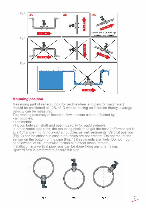
Pipe Location• The six most common installation configurations shown in fig. 1 help in selecting the best location in the pipeline for paddlewheel flow sensor as well for magmeter flow sensor.• The three configurations in fig. 2 ensure that the pipe is always full: for a correct measurement the sensor can NOT be exposed to air bubbles at any time.• The three installations in Fig. 3 should be avoided unless you are absolutely sure the sensor is not exposed to air bubbles.• In gravity-flow systems the connection to the tank must be designed so the level does not drop below the outlet: this to avoid pipe to draw air in from the tank causing a inaccurate measurement of sensor (see Fig. 4).• For more information, please refer to EN ISO 5167-1.• Always maximize distance between flow sensors and pumps.
7
Fig.2
Fig.3
Fig.4
Mounting positionMeasuring part of sensor (rotor for paddlewheel and pins for magmeter) should be positioned at 12% of ID where, basing on insertion theory, average velocity can be measured.The reading accuracy of insertion flow sensors can be affected by:• air bubbles;• sediments;• friction between shaft and bearings (only for paddlewheel).In a horizontal pipe runs, the mounting position to get the best performances is at a 45° angle (Fig. 3) to avoid air bubbles as well sediments. Vertical position (Fig. 2) can be chosen in case air bubbles are not present. Do not mount the sensor on the bottom of the pipe (Fig. 1) if sediments are likely. Do not mount paddlewheel at 90° otherwise friction can affect measurement. Installation in a vertical pipe runs can be done fixing any orientation.Upward flow is preferred to ensure full pipe.

8
WIRING
General recommendation• Always ensure the power supply is switched off before working on the sensor. • Always use a high quality (regulated) DC voltage supply.
WIRING DIAGRAMS
F3.00.H IP68 Sensor Connection to FLS Instruments (except M9.20)
Process connection1. Lubricate the sensor O-rings with a silicone lubricant. Do not use any petroleum based lubricant that may damage the O-rings.2. Lower the sensor into the fitting making sure the alignment tab is seated in the fitting notch.3. Hand tighten the sensor cap. Do not use any tool otherwise cap and/or fitting threads may be damaged.
M9.02 M9.50M9.07M9.08
M9.03 (FLOW SENSOR 2)
M9.03 (FLOW SENSOR 1)M9.20M9.00
M9.10
GND 5 30 16 30 7 37
FREQ. IN 6 28 14 28 8 36
V+ 7 27 13 27 9 35
DIR 6B - 15 29 - -

9
F3.00.H IP65 Sensor Connection to FLS Instruments (except M9.20)
F3.00.C IP65 Sensor Connection to FLS Instruments (only for M9.20)
F3.00.C IP68 Sensor Connection to FLS Instruments (only for M9.20)

10
F3.00.P IP68 Sensor Connection to PLC with NPN Input
F3.00.P IP68 Sensor Connection to PLC with PNP Input
F3.00.P IP65 Sensor Connection to PLC with NPN Input

11
F3.00.P IP65 Sensor Connection to PLC with PNP Input
F3.00.H IP68 Sensor Connection to Other Brand Instruments
2.7Kohm Pull-up resistor may be
F3.00.H IP65 Sensor Connection to Other Brand Instruments
2.7Kohm Pull-up resistor may be

12
F3.00.C IP68 Sensor Connection to Other Brand Instruments
F3.00.C IP65 Sensor Connection to Other Brand Instruments
2.7Kohm Pull-up resistor may be

13
INSTALLATION FITTINGS
Type Description
Plastic Tees• Size: d20 to d50 (0.5” to 1.5”)
• Materials: PVC, PP, PVDF
PVC-U Clamp Saddles• Size: d63 to d225 (2” to 8”)
• Insert Materials: C-PVC, PVDF
316L SS Tees • Size: d63 to d315• Materials: PVC, C-PVC, PP, PE
Metal Strap-on Saddles• Size: DN80 to DN450• Insert Material: C-PVC
• Special order for other sizes
316L SS Weld-on Adapters • Size: d50 to d600 (1.5” to 24”)

14
K-FACTOR TABLES
K-Factor is the number of pulses which a sensor produces for one liter of measured fluid. Here below all K-Factors for water at room temperature are listed. K-Factor values can depend on the installation conditions. K-Factor has to divide the frequency generated by F3.00 in order to achieve the flow rate (l/s). Please contact your dealer for K-Factor values not included in the table.
Installation on PVC pipes
ISO Metric Clamp Saddles for ISO SDR 21 pipes (PN10 up to d 90mm, PN12,5 from d 110mm)
Part No. DN d K-Factor
SVIC063BVC 50 63 21,69SVIC075BVC 65 75 14,98SVIC090BVC 80 90 9,88SVIC110BVC 100 110 6,06SVIC125BVC 110 125 4,59SVIC140BVC 125 140 3,59SVIC160BVC 150 160 2,69SVIC200BVC 180 200 1,65SVIC225BVC 200 225 1,28SVIC063DVC 50 63 21,69SVIC075DVC 65 75 14,98SVIC090DVC 80 90 9,88SVIC110DVC 100 110 6,06SVIC125DVC 110 125 4,59SVIC140DVC 125 140 3,59SVIC160DVC 150 160 2,69SVIC200DVC 180 200 1,65SVIC225DVC 200 225 1,28SMIC250IVC 225 250 1,01SMIC280IVC 250 280 0,79SMIC315IVC 280 315 0,61
ISO Metric PVC Tee Fittings for ISO SDR 21 pipes (female ends for solvent welding)
Part No. DN d K-Factor
TFIV20B 15 20 235,45TFIV25B 20 25 142,46TFIV32B 25 32 91,53TFIV40B 32 40 51,57TFIV50B 40 50 42,89TFIV20D 15 20 235,45TFIV25D 20 25 142,46TFIV32D 25 32 91,53TFIV40D 32 40 51,57TFIV50D 40 50 42,89
BSP Female Threaded PVC Tee Fittings for BS PN12 pipes
(parallel threaded female ends)
Part No. DN R K-Factor
TFFV20B 15 1/2" 235,45TFFV25B 20 3/4" 142,46TFFV32B 25 1" 91,53TFFV40B 32 1" 1/4 51,57TFFV50B 40 1" 1/2 42,89TFFV20D 15 1/2" 235,45TFFV25D 20 3/4" 142,46TFFV32D 25 1" 91,53TFFV40D 32 1" 1/4 51,57TFFV50D 40 1" 1/2 42,89
BS Solvent Welding PVC Tee Fittings for BS PN12 pipes
(female ends for solvent welding)
Part No. DN d K-Factor
TFLV20B 15 1/2" 235,45TFLV25B 20 3/4" 142,46TFLV32B 25 1" 91,53TFLV40B 32 1" 1/4 51,57TFLV50B 40 1" 1/2 42,89TFLV20D 15 1/2" 235,45TFLV25D 20 3/4" 142,46TFLV32D 25 1" 91,53TFLV40D 32 1" 1/4 51,57TFLV50D 40 1" 1/2 42,89
"

15
BS Clamp Saddles for BS PN12 pipes
Part No. DN d K-Factor
SVLC2.0BVM 50 2" 24,10SVLC3.0BVM 80 3" 10,29SVLC4.0BVM 100 4" 5,72SVLC6.0BVM 150 6" 2,48SVLC8.0BVM 200 8" 1,34SVLC2.0DVM 50 2" 24,10SVLC3.0DVM 80 3" 10,29SVLC4.0DVM 100 4" 5,72SVLC6.0DVM 150 6" 2,48SVLC8.0DVM 200 8" 1,34
ASTM SCH. 80 Clamp Saddles for ASTM SCH. 80 pipes
Part No. SIZE d K-Factor
SVAC2.0BVM 2.00" - 29,74SVAC2.5BVM 2.50" - 20,25SVAC3.0BVM 3.00" - 12,36SVAC4.0BVM 4.00" - 6,47SVAC5.0BVM 5.00" - 4,00SVAC6.0BVM 6.00" - 2,68SVAC8.0BVM 8.00" - 1,46SVAC2.0DVM 2.00" - 29,74SVAC2.5DVM 2.50" - 20,25SVAC3.0DVM 3.00" - 12,36SVAC4.0DVM 4.00" - 6,47SVAC5.0DVM 5.00" - 4,00SVAC6.0DVM 6.00" - 2,68SVAC8.0DVM 8.00" - 1,46
NPT Female Threaded PVC Tee Fittings for ASTM SCH. 80 pipes
(NPT threaded female ends)
Part No. SIZE R K-Factor
TFNV20B 0.50" 1/2" 235,45TFNV25B 0.75" 3/4" 142,46TFNV32B 1.00" 1" 91,53TFNV40B 1.25" 1" 1/4 51,57TFNV50B 1.50" 1" 1/2 42,89TFNV20D 0.50" 1/2" 235,45TFNV25D 0.75" 3/4" 142,46TFNV32D 1.00" 1" 91,53TFNV40D 1.25" 1" 1/4 51,57TFNV50D 1.50" 1" 1/2 42,89
ASTM SCH. 80 PVC Tee Fittings for ASTM SCH. 80 pipes
(female ends for solvent welding)
Part No. SIZE d K-Factor
TFAV20B 0.50" 1/2" 235,45TFAV25B 0.75" 3/4" 142,46TFAV32B 1.00" 1" 91,53TFAV40B 1.25" 1" 1/4 51,57TFAV50B 1.50" 1" 1/2 42,89TFAV20D 0.50" 1/2" 235,45TFAV25D 0.75" 3/4" 142,46TFAV32D 1.00" 1" 91,53TFAV40D 1.25" 1" 1/4 51,57TFAV50D 1.50" 1" 1/2 42,89

16
Installation on C-PVC pipes
Installation on PP pipes
ISO metric PVDF Tee Fittings for ISO SDR 21 C-PVC pipes (female ends for solvent welding)
Part No. DN d K-Factor
TFIF20BC 15 20 225,06TFIF25BC 20 25 139,38TFIF32BC 25 32 94,66TFIF40BC 32 40 51,37TFIF50BC 40 50 43,07TFIF20DC 15 20 225,06TFIF25DC 20 25 139,38TFIF32DC 25 32 94,66TFIF40DC 32 40 51,37TFIF50DC 40 50 43,07
ISO Metric PP Tee Fittings for ISO SDR 11 pipes(female ends for socket welding)
Part No. DN d K-Factor
TFIM20B 15 20 212,17TFIM25B 20 25 135,32TFIM32B 25 32 89,36TFIM40B 32 40 48,94TFIM50B 40 50 42,10TFIM20D 15 20 212,17TFIM25D 20 25 135,32TFIM32D 25 32 89,36TFIM40D 32 40 48,94TFIM50D 40 50 42,10
BSP Female Threaded PP Tee Fittings for BS pipes (parallel threaded female ends)
Part No. DN R K-Factor
TFFM20B 15 1/2" 212,17TFFM25B 20 3/4" 135,32TFFM32B 25 1" 89,36TFFM40B 32 1" 1/4 48,94TFFM50B 40 1" 1/2 42,10TFFM20D 15 1/2" 212,17TFFM25D 20 3/4" 135,32TFFM32D 25 1" 89,36TFFM40D 32 1" 1/4 48,94TFFM50D 40 1" 1/2 42,10
ISO Clamp Saddles for ISO SDR 21 pipes
Part No. DN d K-Factor
SVIC063BVC 50 63 21,69SVIC075BVC 65 75 14,98SVIC090BVC 80 90 9,88SVIC110BVC 100 110 6,06SVIC125BVC 110 125 4,59SVIC140BVC 125 140 3,59SVIC160BVC 150 160 2,69SVIC200BVC 180 200 1,65SVIC225BVC 200 225 1,28SVIC063DVC 50 63 21,69SVIC075DVC 65 75 14,98SVIC090DVC 80 90 9,88SVIC110DVC 100 110 6,06SVIC125DVC 110 125 4,59SVIC140DVC 125 140 3,59SVIC160DVC 150 160 2,69SVIC200DVC 180 200 1,65SVIC225DVC 200 225 1,28SMIC250IVC 225 250 1,01SMIC280IVC 250 280 0,79SMIC315IVC 280 315 0,61

17
NPT Female Threaded PP Tee Fittings for ASTM SCH.80 pipes
(NPT threaded female ends)
Part No. DN d K-Factor
TFNM20B 0.50" 1/2" 212,17TFNM25B 0.75" 3/4" 135,32TFNM32B 1.00" 1" 89,36TFNM40B 1.25" 1" 1/4 48,94TFNM50B 1.50" 1" 1/2 42,10TFNM20D 0.50" 1/2" 212,17TFNM25D 0.75" 3/4" 135,32TFNM32D 1.00" 1" 89,36TFNM40D 1.25" 1" 1/4 48,94TFNM50D 1.50" 1" 1/2 42,10
ISO Clamp Saddles for ISO SDR 21 pipes
Part No. DN d K-Factor
SVIC063BME 50 63 27,50SVIC075BME 65 75 18,56SVIC090BME 80 90 12,44SVIC110BME 100 110 7,59SVIC125BME 110 125 5,77SVIC140BME 125 140 4,49SVIC160BME 150 160 3,38SVIC200BME 180 200 2,07SVIC225BME 200 225 1,60SVIC063DME 50 63 27,50SVIC075DME 65 75 18,56SVIC090DME 80 90 12,44SVIC110DME 100 110 7,59SVIC125DME 110 125 5,77SVIC140DME 125 140 4,49SVIC160DME 150 160 3,38SVIC200DME 180 200 2,07SVIC225DME 200 225 1,60SMIC250IME 225 250 1,27SMIC280IME 250 280 0,99SMIC315IME 280 315 0,77
ASTM SCH. 80 Clamp Saddles for ASTM SCH. 80 pipes
Part No. SIZE d K-Factor
SVAC2.0BME 2.00" - 29,83SVAC2.5BME 2.50" - 20,37SVAC3.0BME 3.00" - 12,36SVAC4.0BME 4.00" - 6,47SVAC5.0BME 5.00" - 3,92SVAC6.0BME 6.00" - 1,53SVAC8.0BME 8.00" - 1,44SVAC2.0DME 2.00" - 29,83SVAC2.5DME 2.50" - 20,37SVAC3.0DME 3.00" - 12,36SVAC4.0DME 4.00" - 6,47SVAC5.0DME 5.00" - 3,92SVAC6.0DME 6.00" - 1,53SVAC8.0DME 8.00" - 1,44

18
Installation on PVDF pipes
Installation on PE pipes
ISO Metric PVDF Tee Fittings for ISO SDR 33 pipes (female ends for socket welding)
Part No. DN d K-Factor
TFIF20B 15 20 225,06TFIF25B 20 25 139,38TFIF32B 25 32 94,66TFIF40B 32 40 51,37TFIF50B 40 50 43,07TFIF20D 15 20 225,06TFIF25D 20 25 139,38TFIF32D 25 32 94,66TFIF40D 32 40 51,37TFIF50D 40 50 43,07
ISO Metric PVC Tee Fittings for PE SDR 11 pipes (PE end connectors
for electrofusion or butt welding)Part No. DN d K-Factor
TFIV20BE 15 20 193,70TFIV25BE 20 25 134,07TFIV32BE 25 32 85,29TFIV40BE 32 40 48,68TFIV50BE 40 50 41,68TFIV20DE 15 20 193,70TFIV25DE 20 25 134,07TFIV32DE 25 32 85,29TFIV40DE 32 40 48,68TFIV50DE 40 50 41,68
ISO Clamp Saddles for ISO SDR 33 pipes
Part No. DN d K-Factor
SVIF063BF 50 63 20,58SVIF 075BF 65 75 14,09SVIF 090BF 80 90 9,29SVIF 110BF 100 110 5,69SVIF 125BF 110 125 4,31SVIF 140BF 125 140 3,36SVIF 160BF 150 160 2,52SVIF 200BF 180 200 1,55SVIF 225BF 200 225 1,20SVIF 063DF 50 63 20,58SVIF 075DF 65 75 14,09SVIF 090DF 80 90 9,29SVIF 110DF 100 110 5,69SVIF 125DF 110 125 4,31SVIF 140DF 125 140 3,36SVIF 160DF 150 160 2,52SVIF 200DF 180 200 1,55SVIF 225DF 200 225 1,20
ISO Clamp Saddles for PE SDR 11 pipes
Part No. DN d K-Factor
SVIC063BME 50 63 27,39SVIC075BME 65 75 18,75SVIC090BME 80 90 12,41SVIC110BME 100 110 7,57SVIC125BME 110 125 5,76SVIC140BME 125 140 4,49SVIC160BME 150 160 3,37SVIC200BME 180 200 2,02SVIC225BME 200 225 1,60SVIC063DME 50 63 27,39SVIC075DME 65 75 18,75SVIC090DME 80 90 12,41SCIC110DME 100 110 7,57SVIC125DME 110 125 5,76SVIC140DME 125 140 4,49SVIC160DME 150 160 3,37SVIC200DME 180 200 2,02SVIC225DME 200 225 1,60SMIC250IME 225 250 1,27SMIC280IME 250 280 0,99SMIC315IME 280 315 0,77

19
Installation on Metal pipes316L SS Threaded Tees (BSP Female Threads)
Part No. DN R K-Factor
TFFX20 15 1/2" -TFFX25 20 3/4 157,06TFFX32 25 1" 92,84TFFX40 32 1" 1/4 51,52
Metal Strap-on Saddles mounted on Cast Iron pipes
Part No. DN K-Factor
SZIC080I 80 10,22SZIC100I 100 6,01SZIC125I 125 3,64SZIC150I 150 2,46SZIC200I 200 1,28SZIC250I 250 0,79SZIC300I 300 0,53SZIC350I 350 0,4SZIC400I 400 0,31SZIC450I 450 0,24
Metal Strap-on Saddles mounted on Other Metal pipes
Part No. DN K-Factor
SZIC080I 80 9,61SZIC100I 100 5,22SZIC125I 125 3,31SZIC150I 150 2,22SZIC200I 200 1,23SZIC250I 250 0,75SZIC300I 300 0,52SZIC350I 350 0,43SZIC400I 400 0,32SZIC450I 450 -
316L SS Weld-on Adapters mounted on Other Metal pipes
Part No. DN K-Factor
WAIXL0 40 36,17WAIXL0 50 23,71WAIXL0 60 -WAIXL0 65 13,93WAIXL0 80 9,61WAIXL0 100 5,22WAIXL0 110 -WAIXL0 125 3,31WAIXL0 150 2,22WAIXL0 175 -WAIXL0 200 1,23WAIXL1 225 0.75WAIXL1 250 0,52WAIXL1 300 0,43WAIXL1 350 0,32WAIXL1 400 -WAIXL1 450 0,20WAIXL1 500 -WAIXL1 600 0,14
316L SS Weld-on Adapters mounted on Cast Iron pipes
Part No. DN K-Factor
WAIXL0 40 -WAIXL0 50 -WAIXL0 60 19,78WAIXL0 65 -WAIXL0 80 10,22WAIXL0 100 6,01WAIXL0 110 -WAIXL0 125 3,64WAIXL0 150 2,46WAIXL0 175 -WAIXL0 200 1,28WAIXL1 225 -WAIXL1 250 0,79WAIXL1 300 0,53WAIXL1 350 0,40WAIXL1 400 0,31WAIXL1 450 0,24WAIXL1 500 0,20WAIXL1 600 0,14

20
ORDERING DATAF3.00.H.XX Paddlewheel Flow Sensors (Remote version)
Part No. VersionPower supply
LengthMain
wetted materials
EnclosureFlow Rate
RangeWeight
(gr.)
F3.00.H.01 Hall 5 - 24 VDC L0 CPVC/ EPDM IP68 0.15 to 8 m/s (0.5 to 25 ft./s.) 250
F3.00.H.02 Hall 5 - 24 VDC L0 CPVC/FPM IP68 0.15 to 8 m/s (0.5 to 25 ft./s.) 250
F3.00.H.03 Hall 5 - 24 VDC L1 CPVC/ EPDM IP68 0.15 to 8 m/s (0.5 to 25 ft./s.) 300
F3.00.H.04 Hall 5 - 24 VDC L1 CPVC/FPM IP68 0.15 to 8 m/s (0.5 to 25 ft./s.) 300
F3.00.H.05 Hall 5 - 24 VDC L0 PVDF/EPDM IP68 0.15 to 8 m/s (0.5 to 25 ft./s.) 250
F3.00.H.06 Hall 5 - 24 VDC L0 PVDF/FPM IP68 0.15 to 8 m/s (0.5 to 25 ft./s.) 250
F3.00.H.07 Hall 5 - 24 VDC L1 PVDF/EPDM IP68 0.15 to 8 m/s (0.5 to 25 ft./s.) 300
F3.00.H.08 Hall 5 - 24 VDC L1 PVDF/FPM IP68 0.15 to 8 m/s (0.5 to 25 ft./s.) 300
F3.00.H.09 Hall 5 - 24 VDC L0 316SS/EPDM IP68 0.15 to 8 m/s (0.5 to 25 ft./s.) 600
F3.00.H.10 Hall 5 - 24 VDC L0 316SS/FPM IP68 0.15 to 8 m/s (0.5 to 25 ft./s.) 600
F3.00.H.11 Hall 5 - 24 VDC L1 316SS/EPDM IP68 0.15 to 8 m/s (0.5 to 25 ft./s.) 650
F3.00.H.12 Hall 5 - 24 VDC L1 316SS/FPM IP68 0.15 to 8 m/s (0.5 to 25 ft./s.) 650
F3.00.H.13 Hall 5 - 24 VDC L0 CPVC/EPDM IP65 0.15 to 8 m/s (0.5 to 25 ft./s.) 250
Correction formula for K-Factor calculation according to real internal diameter:
K-Factor_NEW = (K-Factor x ID²) / ID_NEW² ID = Value in the table for the internal diameter (in mm)ID_NEW = New value for the real internal diameter (always in mm)K-Factor = Value in the tableK-Factor_NEW = New K-Factor value for the specified internal diameter
Example:Nominal Pipe Size (DN) = 100 mm New Internal Diameter = 104 mmForumla: K-Factor_NEW = (51.02 x 100²) / 104² = 20,52

21
F3.00.H.14 Hall 5 - 24 VDC L0 CPVC/FPM IP65 0.15 to 8 m/s (0.5 to 25 ft./s.) 250
F3.00.H.15 Hall 5 - 24 VDC L1 CPVC/EPDM IP65 0.15 to 8 m/s (0.5 to 25 ft./s.) 300
F3.00.H.16 Hall 5 - 24 VDC L1 CPVC/FPM IP65 0.15 to 8 m/s (0.5 to 25 ft./s.) 300
F3.00.H.17 Hall 5 - 24 VDC L0 PVDF/EPDM IP65 0.15 to 8 m/s (0.5 to 25 ft./s.) 250
F3.00.H.18 Hall 5 - 24 VDC L0 PVDF/FPM IP65 0.15 to 8 m/s (0.5 to 25 ft./s.) 250
F3.00.H.19 Hall 5 - 24 VDC L1 PVDF/EPDM IP65 0.15 to 8 m/s (0.5 to 25 ft./s.) 300
F3.00.H.20 Hall 5 - 24 VDC L1 PVDF/FPM IP65 0.15 to 8 m/s (0.5 to 25 ft./s.) 300
F3.00.H.21 Hall 5 - 24 VDC L0 316SS/EPDM IP65 0.15 to 8 m/s (0.5 to 25 ft./s.) 600
F3.00.H.22 Hall 5 - 24 VDC L0 316SS/FPM IP65 0.15 to 8 m/s (0.5 to 25 ft./s.) 600
F3.00.H.23 Hall 5 - 24 VDC L1 316SS/EPDM IP65 0.15 to 8 m/s (0.5 to 25 ft./s.) 650
F3.00.H.24 Hall 5 - 24 VDC L1 316SS/FPM IP65 0.15 to 8 m/s (0.5 to 25 ft./s.)

22
F3.00.C.XX Paddlewheel Flow Sensors (Remote version)
Part No. VersionPower supply
LengthMain
wetted materials
EnclosureFlow Rate
RangeWeight
(gr.)
F3.00.C.01 Coil 3 - 5 VDC L0 CPVC/EPDM IP68 0.15 to 8 m/s (0.5 to 25 ft./s.) 250
F3.00.C.02 Coil 3 - 5 VDC L0 CPVC/FPM IP68 0.15 to 8 m/s (0.5 to 25 ft./s.) 250
F3.00.C.03 Coil 3 - 5 VDC L1 CPVC/EPDM IP68 0.15 to 8 m/s (0.5 to 25 ft./s.) 300
F3.00.C.04 Coil 3 - 5 VDC L1 CPVC/FPM IP68 0.15 to 8 m/s (0.5 to 25 ft./s.) 300
F3.00.C.05 Coil 3 - 5 VDC L0 PVDF/EPDM IP68 0.15 to 8 m/s (0.5 to 25 ft./s.) 250
F3.00.C.06 Coil 3 - 5 VDC L0 PVDF/FPM IP68 0.15 to 8 m/s (0.5 to 25 ft./s.) 250
F3.00.C.07 Coil 3 - 5 VDC L1 PVDF/EPDM IP68 0.15 to 8 m/s (0.5 to 25 ft./s.) 300
F3.00.C.08 Coil 3 - 5 VDC L1 PVDF/FPM IP68 0.15 to 8 m/s (0.5 to 25 ft./s.) 300
F3.00.C.09 Coil 3 - 5 VDC L0 316SS/EPDM IP68 0.15 to 8 m/s (0.5 to 25 ft./s.) 600
F3.00.C.10 Coil 3 - 5 VDC L0 316SS/FPM IP68 0.15 to 8 m/s (0.5 to 25 ft./s.) 600
F3.00.C.11 Coil 3 - 5 VDC L1 316SS/EPDM IP68 0.15 to 8 m/s (0.5 to 25 ft./s.) 650
F3.00.C.12 Coil 3 - 5 VDC L1 316SS/FPM IP68 0.15 to 8 m/s (0.5 to 25 ft./s.) 650
F3.00.C.13 Coil 3 - 5 VDC L0 CPVC/EPDM IP65 0.15 to 8 m/s (0.5 to 25 ft./s.) 250
F3.00.C.14 Coil 3 - 5 VDC L0 CPVC/FPM IP65 0.15 to 8 m/s (0.5 to 25 ft./s.) 250
F3.00.C.15 Coil 3 - 5 VDC L1 CPVC/EPDM IP65 0.15 to 8 m/s (0.5 to 25 ft./s.) 300
F3.00.C.16 Coil 3 - 5 VDC L1 CPVC/FPM IP65 0.15 to 8 m/s (0.5 to 25 ft./s.) 300
F3.00.C.17 Coil 3 - 5 VDC L0 PVDF/EPDM IP65 0.15 to 8 m/s (0.5 to 25 ft./s.) 250
F3.00.C.18 Coil 3 - 5 VDC L0 PVDF/FPM IP65 0.15 to 8 m/s (0.5 to 25 ft./s.) 250
F3.00.C.19 Coil 3 - 5 VDC L1 PVDF/EPDM IP65 0.15 to 8 m/s (0.5 to 25 ft./s.) 300
F3.00.C.20 Coil 3 - 5 VDC L1 PVDF/FPM IP65 0.15 to 8 m/s (0.5 to 25 ft./s.) 300
F3.00.C.21 Coil 3 - 5 VDC L0 316SS/EPDM IP65 0.15 to 8 m/s (0.5 to 25 ft./s.) 600

23
F3.00.C.22 Coil 3 - 5 VDC L0 316SS/FPM IP65 0.15 to 8 m/s (0.5 to 25 ft./s.) 600
F3.00.C.23 Coil 3 - 5 VDC L1 316SS/EPDM IP65 0.15 to 8 m/s (0.5 to 25 ft./s.) 650
F3.00.C.24 Coil 3 - 5 VDC L1 316SS/FPM IP65 0.15 to 8 m/s (0.5 to 25 ft./s.) 650
F3.00.P.XX Paddlewheel Flow Sensors (for direct connection to PLC)
Part No. VersionPower supply
LengthMain
wetted materials
EnclosureFlow Rate
RangeWeight
(gr.)
F3.00.P.01 Push-Pull 12 - 24 VDC L0 CPVC/EPDM IP68 0.15 to 8 m/s (0.5 to 25 ft./s.) 250
F3.00.P.02 Push-Pull 12 - 24 VDC L0 CPVC/FPM IP68 0.15 to 8 m/s (0.5 to 25 ft./s.) 250
F3.00.P.03 Push-Pull 12 - 24 VDC L1 CPVC/EPDM IP68 0.15 to 8 m/s (0.5 to 25 ft./s.) 300
F3.00.P.04 Push-Pull 12 - 24 VDC L1 CPVC/FPM IP68 0.15 to 8 m/s (0.5 to 25 ft./s.) 300
F3.00.P.05 Push-Pull 12 - 24 VD C L0 PVDF/EPDM IP68 0.15 to 8 m/s (0.5 to 25 ft./s.) 250
F3.00.P.06 Push-Pull 12 - 24 VDC L0 PVDF/FPM IP68 0.15 to 8 m/s (0.5 to 25 ft./s.) 250
F3.00.P.07 Push-Pull 12 - 24 VDC L1 PVDF/EPDM IP68 0.15 to 8 m/s (0.5 to 25 ft./s.) 300
F3.00.P.08 Push-Pull 12 - 24 VDC L1 PVDF/FPM IP68 0.15 to 8 m/s (0.5 to 25 ft./s.) 300
F3.00.P.09 Push-Pull 12 - 24 VDC L0 316SS/EPDM IP68 0.15 to 8 m/s (0.5 to 25 ft./s.) 600
F3.00.P.10 Push-Pull 12 - 24 VDC L0 316SS/FPM IP68 0.15 to 8 m/s (0.5 to 25 ft./s.) 600
F3.00.P.11 Push-Pull 12 - 24 VDC L1 316SS/EPDM IP68 0.15 to 8 m/s (0.5 to 25 ft./s.) 650
F3.00.P.12 Push-Pull 12 - 24 VDC L1 316SS/FPM IP68 0.15 to 8 m/s (0.5 to 25 ft./s.) 650
F3.00.P.13 Push-Pull 12 - 24 VDC L0 CPVC/EPDM IP65 0.15 to 8 m/s (0.5 to 25 ft./s.) 250
F3.00.P.14 Push-Pull 12 - 24 VDC L0 CPVC/FPM IP65 0.15 to 8 m/s (0.5 to 25 ft./s.) 250
F3.00.P.15 Push-Pull 12 - 24 VDC L1 CPVC/EPDM IP65 0.15 to 8 m/s (0.5 to 25 ft./s.) 300
F3.00.P.16 Push-Pull 12 - 24 VDC L1 CPVC/FPM IP65 0.15 to 8 m/s (0.5 to 25 ft./s.) 300
F3.00.P.17 Push-Pull 12 - 24 VDC L0 PVDF/EPDM IP65 0.15 to 8 m/s (0.5 to 25 ft./s.) 250

24
F3.00.P.18 Push-Pull 12 - 24 VDC L0 PVDF/FPM IP65 0.15 to 8 m/s (0.5 to 25 ft./s.) 250
F3.00.P.19 Push-Pull 12 - 24 VDC L1 PVDF/EPDM IP65 0.15 to 8 m/s (0.5 to 25 ft./s.) 300
F3.00.P.20 Push-Pull 12 - 24 VDC L1 PVDF/FPM IP65 0.15 to 8 m/s (0.5 to 25 ft./s.) 300
F3.00.P.21 Push-Pull 12 - 24 VDC L0 316SS/EPDM IP65 0.15 to 8 m/s (0.5 to 25 ft./s.) 600
F3.00.P.22 Push-Pull 12 - 24 VDC L0 316SS/FPM IP65 0.15 to 8 m/s (0.5 to 25 ft./s.) 600
F3.00.P.23 Push-Pull 12 - 24 VDC L1 316SS/EPDM IP65 0.15 to 8 m/s (0.5 to 25 ft./s.) 650
F3.00.P.24 Push-Pull 12 - 24 VDC L1 316SS/FPM IP65 0.15 to 8 m/s (0.5 to 25 ft./s.) 650

25
F3.01.X.XX Paddlewheel Flow Sensors (Compact version)
Part No. VersionPower supply
LengthMain wetted
materialsEnclosure
Flow Rate Range
Weight (gr.)
F3.01.H.01 Hall 5 - 24 VDC L0 CPVC/EPDM IP68 0.15 to 8 m/s (0.5 to 25 ft./s.) 250
F3.01.H.02 Hall 5 - 24 VDC L0 CPVC/FPM IP68 0.15 to 8 m/s (0.5 to 25 ft./s.) 250
F3.01.H.03 Hall 5 - 24 VDC L1 CPVC/EPDM IP68 0.15 to 8 m/s (0.5 to 25 ft./s.) 300
F3.01.H.04 Hall 5 - 24 VDC L1 CPVC/FPM IP68 0.15 to 8 m/s (0.5 to 25 ft./s.) 300
F3.01.H.05 Hall 5 - 24 VDC L0 PVDF/EPDM IP68 0.15 to 8 m/s (0.5 to 25 ft./s.) 250
F3.01.H.06 Hall 5 - 24 VDC L0 PVDF/FPM IP68 0.15 to 8 m/s (0.5 to 25 ft./s.) 250
F3.01.H.07 Hall 5 - 24 VDC L1 PVDF/EPDM IP68 0.15 to 8 m/s (0.5 to 25 ft./s.) 300
F3.01.H.08 Hall 5 - 24 VDC L1 PVDF/FPM IP68 0.15 to 8 m/s (0.5 to 25 ft./s.) 300
F3.01.H.09 Hall 5 - 24 VDC L0 316SS/EPDM IP68 0.15 to 8 m/s (0.5 to 25 ft./s.) 600
F3.01.H.10 Hall 5 - 24 VDC L0 316SS/FPM IP68 0.15 to 8 m/s (0.5 to 25 ft./s.) 600
F3.01.H.11 Hall 5 - 24 VDC L1 316SS/EPDM IP68 0.15 to 8 m/s (0.5 to 25 ft./s.) 650
F3.01.H.12 Hall 5 - 24 VDC L1 316SS/FPM IP68 0.15 to 8 m/s (0.5 to 25 ft./s.) 650
F3.01.C.01 Coil 3 - 5 VDC L0 CPVC/EPDM IP68 0.15 to 8 m/s (0.5 to 25 ft./s.) 250
F3.01.C.02 Coil 3 - 5 VDC L0 CPVC/FPM IP68 0.15 to 8 m/s (0.5 to 25 ft./s.) 250
F3.01.C.03 Coil 3 - 5 VDC L1 CPVC/EPDM IP68 0.15 to 8 m/s (0.5 to 25 ft./s.) 300
F3.01.C.04 Coil 3 - 5 VDC L1 CPVC/FPM IP68 0.15 to 8 m/s (0.5 to 25 ft./s.) 300
F3.01.C.05 Coil 3 - 5 VDC L0 PVDF/EPDM IP68 0.15 to 8 m/s (0.5 to 25 ft./s.) 250
F3.01.C.06 Coil 3 - 5 VDC L0 PVDF/FPM IP68 0.15 to 8 m/s (0.5 to 25 ft./s.) 250
F3.01.C.07 Coil 3 - 5 VDC L1 PVDF/EPDM IP68 0.15 to 8 m/s (0.5 to 25 ft./s.) 300
F3.01.C.08 Coil 3 - 5 VDC L1 PVDF/FPM IP68 0.15 to 8 m/s (0.5 to 25 ft./s.) 300
F3.01.C.09 Coil 3 - 5 VDC L0 316SS/EPDM IP68 0.15 to 8 m/s (0.5 to 25 ft./s.) 600

26
F3.01.C.10 Coil 3 - 5 VDC L0 316SS/FPM IP68 0.15 to 8 m/s (0.5 to 25 ft./s.) 600
F3.01.C.11 Coil 3 - 5 VDC L1 316SS/EPDM IP68 0.15 to 8 m/s (0.5 to 25 ft./s.) 650
F3.01.C.12 Coil 3 - 5 VDC L1 316SS/FPM IP68 0.15 to 8 m/s (0.5 to 25 ft./s.) 650

27
Part No. Name DescriptionWeight
(gr.)
F3.SP1 4 pole Cable Plug Cable Plug according to DIN 43650 30
F3.SP2.1 Sensor Cap Black Sensor Cap, for Hall version 42
F3.SP2.2 Sensor Cap Red Sensor Cap, for Coil version 42
F3.SP2.4 Sensor Cap Yellow Sensor Cap, for push-pull version 42
F3.SP2.6 Sensor Cap SS AISI 316 Sensor Cap, for SS Hall and Coil versions 205
F3.SP3.1 O-Rings EPDM Sensor body O-rings 4
F3.SP3.2 O-Rings FPM Sensor body O-rings 4
F3.SP4.2 Rotor KIT ECTFE (Halar®) rotor with Machined Ceramic Shaft and Bearings 8
F3.SP4.3 Rotor KIT ECTFE (Halar®) rotor with SS Shaft 8
F3.SP5.1 Sensor Plug CPVC Sensor Plug 140
F3.SP5.2 Sensor Plug PVDF Sensor Plug 150
F3.SP5.3 Sensor Plug Stainless Steel Sensor Plug 470
F3.SP6 Electrical cable Cable (per meter), 22AWG, 3 cond. 28
SPARE PARTS

28
123 4
4-pole Cable PlugSensor CapO-Rings Rotor KIT

29
NOTE

30
NOTE

31
NOTE

32
FIP - Formatura Iniezione Polimeri S.p.A.
Loc. Pian di Parata16015 CasellaGenova - Italy
Tel. +39 010 96211Fax +39 010 9621209
www.flsnet.it I236
6 - I
MF3
00E
- REV
-02
- 06/
2016