fluid viscous dampers: an effective way to · pdf file · 2010-12-14fluid viscous...
TRANSCRIPT

FLUID VISCOUS DAMPERS: AN EFFECTIVE WAY TO SUPPRESS PEDESTRIAN-INDUCED MOTIONS IN FOOTBRIDGES
Philippe DuflotCivil Engineer Taylor Devices Europe Brussels, BE
Doug TAYLORPresidentTaylor Devices IncNorth Tonawanda, USA
Summary
In the civil engineering field, fluid viscous dampers, used extensively in military applications, have found commercial applications on buildings and bridges subjected to seismic and/or wind storm inputs. Because fluid damping technology was proven thoroughly reliable and robust, implementation on footbridges to suppress undesirable pedestrian-induced vibrations is taking place. .This presentation provides a brief overview of fluid damping technology with specific case studies being provided from pedestrian bridges now equipped with fluid viscous dampers. The viscous dampers are used to completely suppress the feedback between the pedestrians and the bridge and/or wind-induced vibrations. Design requirements of viscous damping devices for footbridge are discussed.The tested performance of structures with fluid viscous dampers show that tremendous gains in performance can be realized at relatively low cost.
Key words : pedestrian-induced vibration, damping, harmonic excitation, dynamic response, viscous damper, biodynamic feedback.
1. Introduction
The phenomena of forced harmonic excitation of bridge structures is well understood and has been well documented by many sources. Most military manuals dating back well into the 1800’s have warnings about soldiers marching in step over bridges of any type. What is unique about the footbridges is that resonance may also be occurring without any expected forced motion or marching. Indeed, the pedestrian motion appear to be purely random in nature, but cause resonance of the bridge deck, with vertical and lateral accelerations. When the Millennium Bridge was officially opened to the public on June 10, 2000, immediate problems were noted. Maximum pedestrian loads of 2,000 people filled the entire bridge deck to capacity, with a resulting loading density of approximately 1.5 people per square meter. Under these conditions, the bridge exhibited severe lateral sway in a frequency band of 0.5 to 1.1 Hz, with lateral accelerations of up to 0.25 g. As many as five separate structural modes were being excited, and pedestrians found it virtually impossible to walk on the bridge. Many held on to deck handrails for support. A series of tests were performed to study the observed pedestrian-induced motion. These identified a unique biodynamic feedback phenomenon, later called “synchronous lateral footfall,” which resulted in seemingly random walking motions becoming synchronized over time among members of an unrelated group of people on the bridge.
In essence, when groups of people are on the bridge, the loadings induced by their footfalls are indeed random, up until the point when a significant number of the people would, by pure chance, step in unison. This can produce a tiny, but still perceptible lateral motion at the first lateral mode frequency of the bridge. Depending on group size and location on the bridge, this first lateral mode can be in the range of a normal walking pace, and the bridge structure would respond at

the same frequency, thus providing positive feedback to the pedestrians. This positive feedback can cause other group members to also begin walking in phase with the motion, providing an amplified input to the bridge structure, with the resultant amplified feedback. When the bridge structure is essentially undamped, the amplification can continue until a large number of people either stopped walking, or are unable to walk due to the excessive motion. During the amplification process, the large induced lateral motions also excite higher modes in the bridge structure, causing even more discomfort to the occupants.
2. Potential solutions
Clearly, the solution to the forced harmonic excitation of footbridge involves finding a means to completely eliminate the biodynamic feedback between pedestrians and the bridge.
Numerous concepts that would reduce or eliminate the feedback response must be evaluated.Some of the solutions can be:
■ Stiffening the Bridge Stiffening of the bridge structure can be accomplished by adding bracing or additional piers. Since the stiffening approach would have to shift frequencies as low as 0.50 Hz to values well above 1.0 Hz, a substantial amount of structural modifications can be required. The resultant changes can be exceedingly heavy and costly. More importantly, the unique architecture of the bridge can essentially be destroyed.
The concept of adding additional support piers would not only have a negative architectural impact, but also can impede ship or car traffic below the bridge.
■ Limiting the Allowable Number of People Allowed on the BridgeThis concept is generally unacceptable to the owner.
■ Active ControlThe use of controllable actuators to continuously oppose the cycling input of the pedestrians is theoretically possible for structures, and is within the present state of the art. However, it is generally accepted that control of only one or two vibratory modes is possible at large scale with current technology, far short of the number of modes being excited. In addition, the required actuator response frequencies and forces at any point on the bridge must be able to vary with both the localized and macroscopic crowd sizes. Thus, a robust control solution is required, even if only one or two modes were to be suppressed by active methods. A further issue can be raised with respect to the amount of control power required, and the need for a continuous guaranteed power supply. These issues can not be easily resolved, and make the concept of active control very expensive.
■ Supplemental Passive DampingOne of the most direct solutions to the harmonic excitation utilizes supplemental viscous damping devices to elevate total structural damping levels to the 20% critical range. This can be compared to usually 0.5%-1% critical damping for a structure. The design concept is based on the premise that added damping can reduce resonant deflections to a low level, such that the bridge can no longer provide any appreciable feedback to the pedestrians.
The advantage of added damping in a structure undergoing forced resonance is well understood, although used more often by mechanical engineers in the technology fields of mechanisms and machinery. For a simple spring-mass-damper system, amplitude under steady-state forced resonance is:
where X = Resonant amplitude X0 = Zero frequency deflection of the spring-mass system under the action of a steady force δ = Critical damping factor

= By definition, the magnification factor of the resonant response
Thus, if a simple first order system with 0.5% critical damping is excited by forced resonance, the magnification factor is:
= 1 / 2* (0.05) = 100
If damping in the system is elevated to 20% critical, then the magnification substantially reduces to:
= 1 / 2 * (0.2) = 2.5
Previous studies and tests on scaled structural models with added supplemental damping have been reported by Constaninou and Symans (1992) [2] and Kasalanati and Constaninou (1999) [3]. This research revealed that the addition of viscous damping to a structure tends to suppress the response not only of the damped mode, but also of higher order modes. Thus, implementation of fluid damping technology began relatively swiftly with wind protection usage and seismic protection. Viscous dampers are now also used on footbridges to suppress undesirable pedestrian-induced vibrations.
3. Description of the fluid viscous dampers
Fluid viscous dampers operate on the principle of fluid flow through orifices. A stainless steel piston travels through chambers that are filled with silicone oil. The silicone oil is inert, non flammable, non toxic and stable for extremely long periods of time. The pressure difference between the two chambers cause silicone oil to flow through an orifice in the piston head and input energy is transformed into heat, which dissipates into the atmosphere. The force/velocity relationship for this kind of damper can be characterized as
F = C . V α
Where F is the output force, V the relative velocity across the damper, C is the damping coefficient and α is a constant exponent which is usually a value between 0.3 and 1. Fluid viscous dampers can operate over temperature fluctuations ranging from -40°C to + 70°C.
Notice that there is no spring force in this equation. Damper force varies only with velocity. For a given velocity the force will be the same at any point in the stroke. As dampers provide no restoring force the structure itself must resist all static loads.
Viscous dampers decrease the response of a structure by adding energy dissipation to a structure, which significantly reduces response to any vibration or shock inputs.
3.1 The effect of different values of k, the damping coefficient:
Figure 1 shows the hysteresis loop of a pure linear viscous damper. The loop is a perfect ellipse. The absence of storage stiffness makes the natural frequency of a structure incorporated with the damper remain the same. This advantage simplifies the design procedure for a structure with supplemental viscous dampers.

Figure 1 :Hysteresis loop of viscous damper
Fluid viscous dampers have the unique ability to simultaneously reduce both stress and deflection within a structure subjected to a transient. This is because a fluid viscous damper varies its force only with velocity, which provides a response that is inherently out-of-phase with stresses due to flexing of the structure. Fig 2 shows a plot of force against velocity for several values of k, the damping coefficient. A value of k=1 is the curve for linear damping which is a good place to start in the design of a damping system. The hysteresis loop for a linear damper is a pure ellipse as shown in Fig 1. K=0.3 is the lowest damping exponent normally possible. Fig 2 shows this value provides significantly more force at lower velocities than a linear damper.
Figure 2 : Force against velocity for different exponent values
Linear damping is easy to analyse and can be handled by most software packages. Also linear damping is unlikely to excite higher modes in a structure.Another advantage of linear damping is that there is very little interaction between damping forces and structural forces in a structure.Structural forces peak when damping forces are zero. Between these points, there is a gradual transfer of forces.
For most pedestrian bridges, linear dampers are therefore preferably considered to completely eliminate the biodynamic feedback between pedestrians and the bridge.

4. Damper design requirements
The application of damping devices to the bridge results in several design issues, some of which can be unique to the studied structure.
The primary issue is to address the fact that the dampers must continuously cycle at an average frequency of 1Hz. It is understood that that majority of the cycles can take place at low amplitude, but the total number of cycles required by the owner can be based on a 50 year bridge life. This equates to more than 109 cycles of life, far in excess of normal values for any sort of conventional damping device. Ideally, the damper should be maintenance free for the entire life cycle.
The second issue is that the damper must respond to very small deflections, such as low as 0.025 mm with high resolution, otherwise the suppression of feedback can not be possible until the bridge is already well into resonance. This issue is compounded by the fact that wind, thermal, and static loadings can require quite long total damper deflections (300 mm and even more).
The third issue is that the damper response must have low hysteretic content, to avoid pedestrians sensing the classical “stick-slip” motion of a conventional sliding contact fluid seal, with the resultant perception of instability in the bridge structure. This requirement became even more difficult when taken in context with the extremely long cyclic life. This is because conventional hydraulic practice is to use seals with heavy interference for long life under dynamic cycling. These high interferences in turn generate high seal friction, accentuating the “stick-slip” motion.
The fourth issue is that several distinct designs of dampers can be required per structure, each of which has different output forces, deflections, component equations, and envelope dimensions.
The final design issue is environmental in nature. The dampers are located outdoors, sometimes over a brackish waterway with tidal flows. The design life was such that all major operating elements of the dampers needed to be constructed from inherently corrosion resistant metals that would not degrade over time.
5. Taylor Devices' frictionless damper
To address all the various design issues, a unique and patented damper can be proposed, previously used exclusively for space based systems. These previous applications have similar requirements for long life and high resolution at low amplitudes, but required relatively low damper forces from small, lightweight design envelopes.
A cutaway of a typical frictionless hermetic damper is shown in Figure 3. The most unique elements of this damper are the frictionless seals made from a welded metal bellows. This type of seal does not slide, but rather flexes without hysteresis as the damper moves. Two metal bellows seals are used to seal fluid in the damper. As the damper moves, the two metal bellows alternately extend and retract, by flexure of the individual bellows segments. Since the seal element elastically flexes rather than slides, seal hysteresis is nearly zero. The volume displaced by the compressing bellows passes through the crossover ports to the extending bellows at the opposite end of the damper. While this is occurring, damping forces are being produced by orifices in the damping head, and the pressures generated are kept isolated from the metal bellows by high restriction hydrodynamic labyrinth bushings. Because hydrodynamic bushings are used, no sliding contact with the piston rod occurs, assuring frictionless performance.
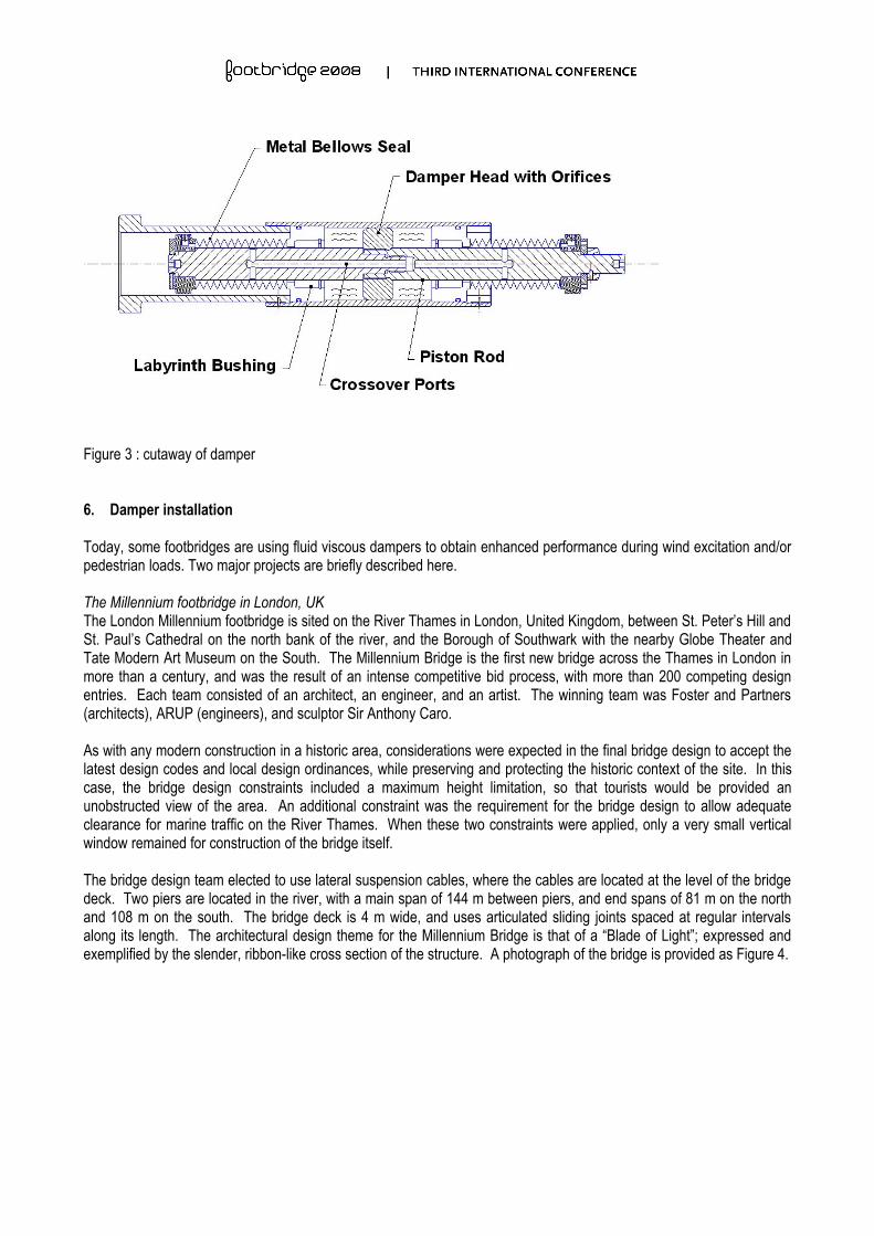
Figure 3 : cutaway of damper
6. Damper installation
Today, some footbridges are using fluid viscous dampers to obtain enhanced performance during wind excitation and/or pedestrian loads. Two major projects are briefly described here. The Millennium footbridge in London, UKThe London Millennium footbridge is sited on the River Thames in London, United Kingdom, between St. Peter’s Hill and St. Paul’s Cathedral on the north bank of the river, and the Borough of Southwark with the nearby Globe Theater and Tate Modern Art Museum on the South. The Millennium Bridge is the first new bridge across the Thames in London in more than a century, and was the result of an intense competitive bid process, with more than 200 competing design entries. Each team consisted of an architect, an engineer, and an artist. The winning team was Foster and Partners (architects), ARUP (engineers), and sculptor Sir Anthony Caro.
As with any modern construction in a historic area, considerations were expected in the final bridge design to accept the latest design codes and local design ordinances, while preserving and protecting the historic context of the site. In this case, the bridge design constraints included a maximum height limitation, so that tourists would be provided an unobstructed view of the area. An additional constraint was the requirement for the bridge design to allow adequate clearance for marine traffic on the River Thames. When these two constraints were applied, only a very small vertical window remained for construction of the bridge itself.
The bridge design team elected to use lateral suspension cables, where the cables are located at the level of the bridge deck. Two piers are located in the river, with a main span of 144 m between piers, and end spans of 81 m on the north and 108 m on the south. The bridge deck is 4 m wide, and uses articulated sliding joints spaced at regular intervals along its length. The architectural design theme for the Millennium Bridge is that of a “Blade of Light”; expressed and exemplified by the slender, ribbon-like cross section of the structure. A photograph of the bridge is provided as Figure 4.

Figure 4 : The Millennium Bridge
All parts were designed with low stress levels to provide an endurance life in excess of 2 x 10⁹ cycles. A total of 37 dampers were constructed, of 7 different types.
To assure a high resolution output, all damper attachment clevises are fabricated with fitted spherical bearings and fitted mounting pins, such that zero net end play exists in the attachment brackets.
Figures 5 through 7 are a sampling of the installed dampers.
Figure 5 : Vertical dampers

Figure 6 : Pier dampers
Figure 7 : Chevron dampers
Tests performed on the footbridge proved that the damped bridge structure perform superbly:
■ Peak measured accelerations are reduced from 0.25 g undamped to 0.006 g damped.■ Dampers reduce the dynamic response by at least 40 to 1 for all modes.■ No resonance is noted of any mode. ■ No observable biodynamic feedback occurs.

The Simone de Beauvoir footbridge in Paris, FThe Simone de Beauvoir passerelle links the new French National Library and the terrace of the large Bercy urban park in the 13th arrondissement of Paris, France over the river Seine. The Simone de Beauvoir footbridge, the thirty seventh bridge in Paris, is part of a programme of a considerable urbanisation of the city’s eastward driven urban development.
The 304m long footbridge has three elements: a 194 meter central span formed from a slender arch working in compression and a suspended convex part working in tension, and two secondary side spans. The arch and catenary are connected to the abutments which, seen from the side, form a rigid triangle articulated at its base and fixed at its summit.
Figure 8 : Simone de Beauvoir passerelle
4 viscous dampers of 3 different types are placed at the ends of the connection footbridge to provide 10% critical damping; 2 dampers installed in the transversal direction of the bridge and 2 dampers in the longitudinal direction. The series of various tests performed on the bridge have confirmed the efficiency of the viscous dampers to reduce horizontal motions due to pedestrians and fully meet the comfort criteria defined by the owner. The transversal viscous dampers are also used to to suppress the anticipated wind-induced accelerations.
Figure 9 : Transversal damper, BNF side
7. Conclusion
Viscous dampers providing critical damping to a pedestrian bridge allow the use of unique bridge architecture, even when the bridge has modal frequencies which are coincident with normal walking motions of pedestrians. The use of supplemental fluid dampers eliminates the potential for undesirable pedestrian-induced vibrations and biodynamic feedback occurring between the pedestrians and the bridge structure. The application of damping devices to the bridge results in several design issues, some of which can be unique to the studied structure. Frictionless viscous dampers can be proposed for continuous cycling.
8. References
[1] DALLARD P., et al, “The London Millennium Footbridge,” The Structural Engineer, Volume 79/No. 22, November 20, 2001,Pg. 17.
[2] CONSTANTINOU M., SYMANS M., “Experimental and Analytical Investigation of Seismic Response of Structures with Supplemental Fluid Viscous Dampers,” Technical Report NCEER-92-0032, National Center for Earthquake Engineering Research, Buffalo, NY.,1992.
[3] KASALANATII A., CONSTANTINOU M., “Experimental Study of Bridge Elastomeric and Other Isolation and Energy Dissipation Systems with Emphasis on Uplift Prevention and High Velocity Near-Source Seismic Excitation,” Technical Report MCEER-99-0004, Multidisciplinary Center for Earthquake Engineering Research, Buffalo, NY., 1999.