viscous dampers: practical application issues for the ... · viscous dampers: practical application...
TRANSCRIPT

Viscous DAMPERS:
Practical Application Issues for the Structural
Engineer
by
AMY HWANGB.S., Civil and Environmental Engineering
Massachusetts Institute of Technology, 1997
Submitted to the Department of Civil and Environmental EngineeringIn Partial Fulfillment of the Requirements for the Degree of
MASTER OF ENGINEERINGIN CIVIL AND ENVIRONMENTAL ENGINEERING
at theMASSACHUSETTS INSTITUTE OF TECHNOLOGY
June 1998
C 1998 Amy HwangAll rights reserved
The author hereby grants to MI. T. permission to reproduce and distribute publicly paper and electroniccopies of this thesis document in whole or in part.
Signature of the Author _
Certified by
V Amy HwangDepartment oftCivil and Environmental Engineering
May 8, 1998
J Jerome J. Connor, Jr.Professor of Civil and Environmental Engineering
Thesis Supervisor
Joseph SussmanChairman, Department Committee on Graduate Studies
Accepted by
JUN 0?2998b f"-"*

Viscous Dampers:
Practical Application Issues for the Structural Engineer
by
AMY HWANG
Submitted to the Department of Civil and Environmental Engineeringon May 8, 1998 in partial fulfillment of the requirements
for the Degree of Master of Engineering inCivil and Environmental Engineering
Abstract
Only in recent years have fluid viscous dampers (FVDs) been incorporated intobuilding designs and retrofits in the United States to control the seismic and windresponse of structures. They have been found to be an effective way of introducingdamping to a structure to decrease building displacements. However, in Japan andseveral other countries, the FVD technology has been incorporated into buildings sincethe early 1990s and has been used widely on a much smaller scale for decades in thenuclear, mechanical, and automotive industries. In the U.S., this can be due to the ideathat much of the work being performed in academic institutions to understand and modeltheir behavior and their interaction with the structure it is attached to is often impracticalto the practicing engineer and repetitive, with each researcher deriving their ownanalytical model for use. There remains no rational methodology for determining theoptimal damping for a building, with research focusing more on deriving analyticalmethods rather than procedural methods, which the practicing engineer is accustomed to.The technology, therefore, remains to be widely accepted or even considered. An attemptis made here to address some of the relevant issues that a practicing design engineerwishing to incorporate FVDs would need to consider. A discussion on the availableguidelines for design, other energy dissipation alternatives, and current procedures beingfollowed for FVD design and analysis is provided.
Thesis Supervisor: Jerome J. Connor, Jr.Title: Professor of Civil and Environmental Engineering

Acknowledgments
Firstly, I want to thank my thesis advisor, Professor Connor, for his supportthroughout this thesis writing, but also through the M.Eng program in general. Hisunderstanding of my interests and his efforts to ensure my academic growth andsatisfaction, in addition to those of Charles Helliwell, were invaluable to me throughoutthe whole program.
I also want to thank various outside contacts, whose enthusiastic help I could nothave done without - Susan Tubbesing, executive director of EERI, for her eager help andremarkable support and direction during the initial stages of my research; Chuck James,information systems manager at the EERC of UC Berkeley, for the helpful informationhe provided; Ugo Morelli, project officer at FEMA for his useful leads; and Prof. DanAbrams, center director at the Mid-America Earthquake Center for his insight. Withrespect to my research efforts, however, I am especially grateful to Cheryl Sima, assistantlibrarian for civil and environmental engineering. Without her efforts to obtain articlesand documents for me when I thought I had exhausted all my possibilities, I would stillbe looking for another thesis topic.
On a personal level, I want to officially thank my two civil engineering/architecture mentors who have gotten me through many questions and doubts about thisfield and in my life in general - Jimmy Su and Deanna Kwan. My mom, my sister Ellen,and my close friends are also high up on my list of people to thank, particularly for theirsupport and understanding even just through this year alone. Finally, and mostimportantly, I give all the recognition for the completion of this thesis, and for that matterfor my whole life's "accomplishments," to Jesus Christ, my Savior and Lord, whodeserves all the glory.

1.0 Introduction 5
2.0 Motivation and Scope 6
3.0 Background Information on Fluid Viscous Dampers 8
3.1 Description 8
3.2 Structural Function and Implementation 10
4.0 Selection of Fluid Viscous Damper Solution 15
4.1 Fluid Viscous Dampers vs. Traditional Design 15
4.2 Fluid Viscous Dampers vs. Other Passive EnergyDissipation Devices 19
42. 7 Fluid Viscous Dampers vs. Viscoelastic Dampers 19
4.2.2 Fluid Viscous Dampers vs. ADAS Dampers 21
4.2.3 Fluid Viscous Dampers vs. Friction Dampers 22
4.2.4 Hybrid Solution 23
5.0 Overview of Existing Design Guidelines 25
6.0 Design with Fluid Viscous Dampers 30
6.1 Overall Design Procedure 31
6.2 Computer Modeling 31
6.3 Optimal Damper Placement 36
7.0 Conclusions 42

1.0 Introduction
Recently, with a general heightened awareness of seismic risks among the
structural engineering community, the use of seismic devices in buildings to control the
seismic response of a structure is on the rise. This may be, in part, in response to the
extensive structural connection and member failures caused by the 1994 Northridge
earthquake in California. In light of the Northridge building failures, the fundamental
design philosophy of seismic design to depend on the ductile behavior of the structural
material to absorb earthquake energy was questioned. Thereafter, despite previous
resistance by structural engineers to incorporate the unconventional mechanisms into
their traditionally-designed structure, structural control through the use of energy
dissipation devices became a more serious option for many designers [13].
Fluid viscous dampers (FVDs), one example of these untraditional energy
dissipation devices, only began to be used in buildings in the early 1990s. Since their
introduction to the general structures industry to decrease seismic or wind response, fluid
viscous dampers have been used and are planned for use in several new and retrofitted
buildings in Japan, Italy, Mexico, California, and occasionally in other regions of the U.S.
In Japan and, on a lesser scale in Italy, the understanding and implementation of FVD
technology as applicable to buildings developed more rapidly than in the U.S. Only in
the late 1990s have FVDs been incorporated seriously into building designs and retrofits
in the U.S. However, much work has yet to be done to make structural design with
devices a viable, generally-accepted alternative to traditional earthquake or wind design.

2.0 Motivation and Scope
In a recent Earthquake Engineering Research Institute (EERI) symposium in San
Francisco, Professor Emeritus V.V. Bertero of U.C. Berkeley, pioneer in the area of
energy dissipation devices, remarked that there is a dangerously widening gap between
academic researchers and practioners of seismic engineering. He criticizes the "confusing
and often redundant research pouring out of academia" [18]. Practicing structural
engineers not only cannot keep up with the various research findings, but oftentimes find
the results hard to incorporate into their traditional design methods. In the case of the
large scale fluid viscous damper, this is compounded by its roots in the nuclear,
mechanical, aerospace defense, and automotive industries. Hence, it is no wonder that
structural engineers feel that they lack the background and knowledge to design with
these energy dissipation devices. The result is the slow integration of this innovative
technology into the structural engineering community and a lack of guidance or a
consistent design procedure.
The motivation for this thesis, then, is to add cohesiveness to research in order to
help the structural engineer design using energy dissipation devices, in particular using
fluid viscous dampers. An attempt is made here to address the main issues that need to
be considered in design in a way that is relevant to a practicing engineer familiar with the
conventional method of lateral load design. Much attention is paid to the computer
analysis required for design since currently many design issues are raised in this area due
to the lack of appropriate software for damper design. Although viscous dampers may
also be used for wind resistance in tall buildings, this thesis will focus primarily on their
effectiveness in resisting seismic loads. Additionally, concentration is on the use of
passive viscous dampers throughout the building height, as opposed to their use in active
control measures. Limited review of the current guidelines for the structural design with
dampers available is also provided. Although the U.S. lags behind Japan in regards to
FVD development in the construction industry, all discussions in this thesis are limited
primarily to the state of understanding and procedures followed by researchers and
practitioners in the U.S. in efforts to be most applicable to structural design as understood
and carried out by U.S. design engineers.

3.0 Background Information on Fluid Viscous Dampers
3.1 Description
For the structural engineer unfamiliar with the technology of the fluid viscous
damper, a brief summary is provided here, while limited descriptions of the other energy
dissipation devices are given in Section 5 only as they are relevant to the understanding
of their differences with respect to the fluid viscous damper.
The fluid viscous damper as used in structures works much like a shock absorber
works within a car, but on a much greater scale. Currently, the primary manufacturer of
FVD's in the U.S. is Taylor Devices Inc., based in North Tonawanda, NY [24]. Only
recently have Taylor Devices begun manufacturing their FVD to the general construction
industry, while previously they manufactured it solely for the defense industry for use in
the classified MX Missile and Stealth Bomber [23]. The Taylor Devices' FVD (see
Figure 1) consists of a stainless steel piston filled with silicon oil, which is pushed
through a bronze orifice. It is the transfer of fluid from chamber to chamber and the
resulting pressure difference that provides the damping force.

SEAL RETAINER HIGH STRENGTH CYLINDER ACCUMLATORACETAL RESIN HOUSING
Figure 1: Construction of a fluid viscous damper
At frequencies below 4 Hz, the FVD acts in a linear fashion; that is, they are dependent
only on velocity, providing only damping to the structure. Above 4 Hz, they tend to
contribute to stiffness as well, as shown by the equation:
F+ A P = Cou" (1)
where F is the output force, A is the relaxation time, Co is the damping constant at zero
frequency, tu is velocity, and n is the damping exponent dependent on the shape of the
piston head. However, for practical purposes, the A term may be neglected since 4 Hz
is usually higher than the frequencies of the dominant modes of vibration for the analyzed
structure when subjected to earthquake loads. Additionally, although n may vary for
structural applications from 0.3 to 1.0, unless specific response limitations above a given
velocity are necessary, structural FVDs are generally designed for a value of n = 1.
Dependent on the damper diameter and orifice area, the damping constant, Co, is
the most important variable in this equation. Typically given in units of lb-sec/in, the
damping constant is specified by the structural engineer and, along with the maximum
velocity for the building, is sufficient information for the manufacturer to supply the
necessary equipment. Depending on the damping requirements of the building, the
resulting force may range anywhere from 2 kips to 2000 kips.
3.2 Structural Function and Implementation
When implemented within the lateral load resisting system of a structure, FVDs
greatly improve a structure's response to lateral loads. They do this by increasing the
damping ratio (Q) from 2%-5%, typical for buildings, to 20%-30% of critical, which
greatly reduces the building's acceleration and displacement. In contrast, at 2%-5%
damping, when relying on the inherent damping capability of the structure, the building is
relying on the inelastic deformation of its members to absorb the energy transferred to the
building by the seismic. FVDs have been used previously for decreasing the structural
response for both new building projects and retrofit projects.
The dampers may be installed within the building's height to complement the
traditional lateral load resisting system, either along the length of the lateral braces or
horizontally at the base or top of the bracing system. For diagonal bracing, they can be
installed in different configurations as shown typically in Figures 2 and 3, both of which
were implemented in the retrofit of the Stockton City Hall [7]. For chevron bracing,
typical configurations are shown in Figures 4 and 5, the latter being the configuration
used for the Sacramento Pacific Bell 911 Facility retrofit [7]. Additionally, FVDs may

also be used as an energy dissipator in conjunction with base isolation methods. Figure 6
shows an example of this implementation, as used in the hybrid seismic resistance system
of the San Bernadino County Medical Center building complex [2]. Regarding the
selection between these different configurations, no further discussion will be provided
due to the lack of available research on this issue.
Figure 2: Typical implementation of a FVD with diagonal bracing (1)
----~

Figure 3: Typical implementation of a FVD with diagonal bracing (2)
STEEL CHEvoZtBRACE
Figure 4: Typical implementation of a FVD with chevron bracing (1)

STRUCTURAL STEEL
01A PMRAMiq
STRUCTURAL STEELCOL UM S--TYP
DSL Cx I . CHAM EL
-CSX8. Z Gu IDE RAIL
CONtI APfA OOR"ID AiPMRAGM T
VI SCOUS DAMPER30k VEYLOCITY:4"/SECTYPICAL (2 TOTAL)
Figure 5: Typical implementation of a FVD with chevron bracing (2)
Figure 6: Typical base isolation solution with FVDs
OR I YCRBOX
ANCHOR-TYP(2 TOTAL)
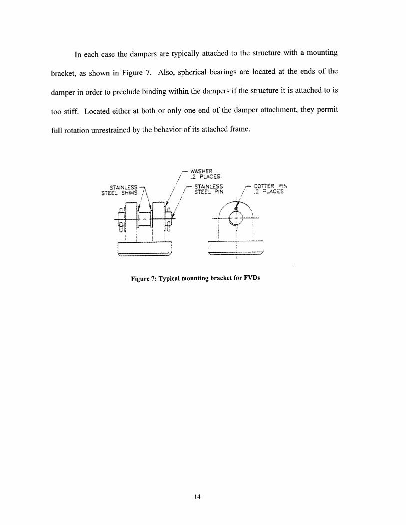
In each case the dampers are typically attached to the structure with a mounting
bracket, as shown in Figure 7. Also, spherical bearings are located at the ends of the
damper in order to preclude binding within the dampers if the structure it is attached to is
too stiff. Located either at both or only one end of the damper attachment, they permit
full rotation unrestrained by the behavior of its attached frame.
-WASHER
, 2 iPLACES
STAINLESS -STAINLSS - COTTER :1N
STE-L SHIMS \ STEEl PIN 2 =-ACES
Nw.. --- --
Figure 7: Typical mounting bracket for FVDs

4.0 Selection of Fluid Viscous Damper Solution
The purpose of this section is not to argue for the use of FVDs over the traditional
design solution or over other passive energy dissipation devices. Rather, this section is
an effort to help the designer choose which solution is the most appropriate for the project
being considered.
4.1 Fluid Viscous Dampers vs. Traditional Design
In order to select the fluid viscous damping solution as the appropriate solution
for a project, the resulting benefits must obviously outweigh those of the traditional
design. Therefore, it is necessary to first define the performance requirements for the
building in regards to desired response in the event of an earthquake and as well as in its
aftermath.
As previously mentioned, in conventional seismic design, energy dissipation is
dependent on the inelastic behavior of its structural components. The amount of
hysteretic behavior is dependent on the resulting inter-story displacement. For a typical
building, story displacement ratios (story drift/height of floor) of less than 0.003 still act
elastically, producing no energy dissipation (Figure 8). However, for greater story drifts,
the inelastic deformation of the structural elements occurs. Since inelastic deformation
usually involves structural damage to a certain degree, repair of such elements may be
necessary [1].

lon I olgend square uin:s 0-
-0 012 -0-006 n (mn- 0.112
Displacement, A 1IH
(b)
Figure 8: Hysteretic behavior of a typical single story of aconventional earthquake-resistant structure
In conventional seismic design, given that inelastic deformation will occur, members and
connections are designed so at least the integrity of the structure is not compromised after
an earthquake. After the Northridge earthquake, traditional connection details that were
thought to be adequate for maintaining structural integrity were questioned. Many new
guidelines for connection detailing were published and much more attention given to
their design (e.g. FEMA 267 [9]). However, even with the new details, repairs may still
be necessary depending on the extent of inelastic deformation. In contrast, the use of
viscous dampers allows the rest of the structure to remain elastic, while the dampers
themselves supply the necessary damping to dissipate the energy. Furthermore, they are
able to provide much higher damping forces than conventionally designed structures,
which in the end leads to smaller building displacements.
Despite the benefit of eliminating repair costs in the future, there usually is a
trade-off of higher initial costs. This, however, will vary depending on the project being

considered. At this point in the game, even by those that design with devices, dampers
are generally not considered for new buildings since their high costs (according to 1997
values, approx. $7,000 for a 150-kip damper [17]) do not offset the conventional retrofit
costs of merely increasing the strength of the members or ductility of the connections.
Exceptions for new buildings may include structures that have high performance
requirements, such as those that may apply for critical facilities that need to remain
operational such as fire or police stations, hospitals, or bridges. In the case of retrofits,
though, the damper option is more attractive. In historic buildings, for example, many
times there are limiting architectural restraints, perhaps in the form of space requirements
or cladding limitations that make strengthening not possible or if the ductility of the
current members is limited. In these instances, the viscous damper solution should
seriously be considered and compared with respect to life-cycle costs.
As an example, in the design of the steel pyramid building that was newly built as
the national headquarters for The Money Store in Sacramento, CA [13], the advantages
and disadvantages of the dampers were weighed. In this case, reducing the displacement
caused by earthquake loads with shear walls or bracing would have decreased the
fundamental period (T) of the building. It, therefore, would have shifted the building
period, as well as resulting building acceleration, to levels that could potentially cause
resonant behavior with the short period earthquake loading. In addition, the amount of
shear walls needed would have interfered with the space requirements. If conventional
bracing were to be implemented, their placement would also be limited since they would
cause column forces that are in phase with the frame forces. FVDs, on the other hand,
cause forces 900 out of phase with the frame forces, causing no additional strain on the
columns. This is true since FVDs are dependent on velocity, which is zero at the point of
maximum displacement causing the FVD force to also be zero at this point of maximum
column strain.
The problem of space limitations was also seen in the retrofit of the Los Angeles
City Hall [22], where traditional shear walls added to the 2 4 th floor would have increased
the acceleration of the floor and caused damage to the exterior facade and emergency
telecommunication system. Therefore, FVDs were used on this top floor. On the other
hand, for the ground floor of the L.A. City Hall, it was determined that the traditional
reinforced concrete walls were more effective. In this case, the conventional solution
allowed additional strength to be added to the frame, a redistribution of the overturning
forces, and a reduction of the building's period of vibration. For the L.A. City Hall, a
reduction in the building's inherent period was actually desirable in order to make the
base isolation solution more effective by keeping the structure's seismic response elastic.
In addition to building limitations, when considering FVDs with respect to
traditional methods, the additional constraints on conventional retrofitting techniques that
have been imposed after the Northridge Earthquake should also be accounted for. In a
five-story steel moment frame hospital [7], for example, all 480 moment frame joints
needed to be strengthened according to the new requirements. However, by adding
FVDs, the resulting flange stress in the beam-columns was so low that they no longer
needed to be modified by the Northridge provisions.

4.2 Fluid Viscous Dampers vs. Other Passive Energy DissipationDevices
Currently, there are four other feasible energy dissipation device options that have
been previously implemented in the U.S. - viscoelastic (VE) dampers, one type of which
has been developed by 3M Corporation [6]; ADAS dampers, which are a type of
hysteretic metallic dampers manufactured by CounterQuake Corporation [25]; friction
dampers, one type of which has been developed by Fluor-Daniel; and a hybrid system of
energy dissipation/absorption techniques. A brief description will be provided here only
in relation to their advantages or disadvantages over fluid viscous dampers.
4.2. 1 FVDs vs. Viscoelostic Dampers
Viscoelastic dampers behave much like viscous dampers except they contribute
added stiffness, hence requiring a non-linear damping element and non-linear model to
define their behavior. They typically consist of metal plates that are separated by a
viscoelastic polymer material (acrylic copolymers in the 3M product) which are attached
by epoxy to the plates (see Figure 9) and, in some cases, to the structure.
Viscoelastic material .....
Figure 9: Typical viscoelastic damper
Their drawbacks in the past include unstable behavior under variant temperatures. At low
temperatures the force increases greatly causing overloading of the epoxy bond, while at
high temperatures the output of the device reduces significantly [24]. This problem is
compounded by the fact that they are usually designed using the linear Kelvin-Voigt,
elastic spring and dashpot, model, given simply by the equation:
F = Ku + C zi (2)
It is clear that this model does not account for the VE damper dependence on ambient
temperature, excitation frequency, or shear strain damping [8]. Therefore, more complex
analytical modeling is needed when designing with VE dampers. Meanwhile, FVD
behavior is stable over a temperature range of -40oF to 160oF and do not have welds or
bonds that may be overstrained.
In addition, as mentioned previously, FVDs cause column loads that are out of
phase with the regular column stresses since they are dependent on velocity alone.
Conversely, VE dampers cause in-phase column stresses and, for strong earthquake loads,
even high stresses independent of the building displacement.
However, these disadvantages can be designed for and may be outweighed by the
necessity of adding stiffness to the building. For instance, additional stiffness may be
needed in order to help the structure behave elastically under seismic loads [7]. In
addition, research at the Waseda University in Japan [20]supports the use of viscoelastic
dampers versus viscous dampers because they have been shown to respond well under
unforeseen strong ground motion. Meanwhile, they found viscous dampers to be not as

effective under unexpected medium to strong ground motions since the energy dissipation
at this level is dominated by yielding of the system, rather than damping.
4.2.2 FVDs vs. ADAS Dampers
For metallic hysteretic dampers, energy dissipation is achieved by the inelastic
yielding of multiple steel plates, as shown in Figure 10. ADAS (Added Damping And
Stiffness) dampers are one type of hysteretic damper.
Shaped steel plates -
Figure 10: Typical hysteretic damper
They provide both stiffness and damping - contributing stiffness up till the point of metal
yielding and damping for more extreme excitations. However, the danger and drawback
of providing stiffness is the additional base shear that results because of the stiffening.
For example, in the comparative analysis of the retrofit of a 10-story office building in
Almeda Park, Mexico City between ADAS dampers and FVDs, the ADAS dampers were
able to increase the first floor stiffness by 30%. However, correspondingly, they
increased the base shear by 20%. Therefore, in order for the ADAS dampers to be more
cost effective, the necessity for additional stiffness must offset the cost of strengthening
the structure itself.

4.2.3 FVDs vs. Friction Dampers
Frictional damper technology as used in buildings is much older than that of the
FVD, dating back to the 1980s. Stiffness and damping is provided in these devices by
frictional sliding between steel plates or between rubber pads and steel plates (Figure 11).
/"N
Figure 11: Typical friction damper
Research on this latter form of the friction damper at Cornell University [16]
provides insight into the advantages and disadvantages of their use. Since frictional
damper forces are dependent on the current value of stiffness, their effectiveness is seen
to be dependent on the specific ground motion being applied and the building's period of
vibration. Experiments reveal that for seismic loadings with a gradual buildup of
acceleration, friction dampers are successful in reducing the maximum story drift and
base shear. However, for impulsive type loading, the stiffness of the friction dampers
may actually increase the resulting peak displacement and force levels, while the
damping contribution would not be large enough to counteract this increase. For friction
dampers, this additional damping is usually in the neighborhood of 10%, while for FVDs
the dampers provide damping values of around 20%-30%. Therefore, when considering
friction dampers versus FVDs, it is important to use time history records that are

representative of the building's region since this will play an important role on the
friction dampers' relative effectiveness, keeping in mind that for earthquakes with few,
but strong, cycles of excitation, there is little effective damping.
Additionally, since friction dampers are independent of velocity and
displacement, under thermal stresses there is a constant force output from the dampers,
which then causes continual stresses on the columns which may not be designed for. To
make matters worse, these column stresses are also in phase with the regular column
stresses. Relative to the FVD, the friction damper also falls short in the area of post
seismic conditions since it does not allow the building to return to its original position,
but remains deformed.
4.2.4 Hybrid Solution
In many cases, the compromise to the various advantages of each type of energy
dissipation devices is to incorporate more than one device into a hybrid design. A hybrid
solution is also used to refer to a design that uses more than one method of motion
control. This may involve using a base isolation solution in conjunction with viscous
dampers located throughout the structure since FVDs have been proven in the past to
reduce building displacement; or it may involve taking advantage of the cheaper,
traditional stiffening techniques on certain floors and FVDs and/or viscoelastic dampers
on others. Therefore, the conventional building design or existing building design must
be evaluated with respect to the established parameters in terms of its period of vibration
relative to the excitation period from seismic loading, its resulting story drifts, its story

accelerations, its base shear, and overturning moments. When considering a particular
damping device to solve one or more of these problems, the effects it may have on the
other aspects of building behavior must be considered and compensated for.
For instance, in the design of the San Bernadino County Medical Center in
California [2], a hybrid energy dissipation system was used. The base was isolated with
linear and non-linear rubber bearings, with viscous dampers added at the plane of
isolation as well. Non-linear isolators were included in order to provide lateral stiffness
for the base isolation system, which then controls the fundamental period of the building.
However, although the building acceleration and forces were reduced, building
displacement was still unacceptable. In order to control the displacement, the non-linear
bearings would need to be further stiffened, which would then increase the base shear
applied to the building. Therefore, since FVDs minimally affect the building period, and
therefore the base shear of the building, adding FVDs at the base provides the necessary
reduction of displacement without posing additional loads on the foundation.

5.0 Overview of Existing Design Guidelines
Formal guidelines that exist to aid the structural engineer in structural design with
dampers are limited. A preliminary design code has been published by the Structural
Engineers Association of Northern California (SEAONC) in 1993 entitled Tentative
General Requirements for the Design and Construction of Structures Incorporating
Discrete Passive Energy Dissipation Devices [21]. It is intended to later supplement the
SEAOC code as the "Green Book." While an important step towards developing a
consistent design procedure, the code is very limited and general, lacking sufficient detail
to aid the engineer in a complete design. It concedes that since the technology is very
new, the methods adopted are highly conservative, which may not lead to the most
effective damper design. They call for the use of response spectrum analysis, provided
that the lateral force resisting elements remain elastic. If nonlinear viscous damper
behavior is to be designed for, an additional nonlinear time history analysis is required.
They also specify when the Design-Basis Earthquake (DBE) (earthquake forces that have
a 10% probability of being exceeded in 50 years) and when the Maximum Capable
Earthquake (MCE) (earthquake forces that have a 10% probability of being exceeded in
100 years or sometimes defined with a 2% probability in 50 years) are to be used in
different parts of the analysis. They also require that the minimum design base shear be
calculated using the response reduction factors, Rw, given in Table 1 and further
magnified by the modification factors, a, given in Table 2.

Table 1: Revised Response Modification Factors (R,) as given in the SEAONC code
Basic Structural System Rw
Building Frame System 10
Moment-Resisting Frame System 10
Dual System 12
Table 2: Magnification Factors (a) as given in the SEAONC code
Basic Structural System a
Structural Steel 1.7
Reinforced Concrete 1.4
The code also gives several provisions for experimental testing of the damper set-up and
assembly to verify the design if this is considered necessary by the structural engineer.
More practicable provisions are given on the use of control devices in retrofit
design, however, in a chapter in the recent FEMA 273, NEHRP Guidelines for the
Seismic Rehabilitation of Buildings recently published in October 1997 [14]. The
guidelines specify practical equations for analysis using linear static procedures, linear
dynamic procedures, nonlinear static procedures, and nonlinear dynamic procedures. For
a viscous damper, using the static procedures, the effective damping, eff , for the
building is taken
as:
W(
eff = " -J (3)4;T Wk

where / is the damping inherent in the framing system (generally taken as 5%), Wj is
work done by device j in one complete cycle of loading associated with floor
displacements 35, and Wk is the maximum strain energy defined as:
1Wk = F, (, (4)
where Fi is the inertia force at floor i. Meanwhile, the work done by each devicej is:
27f2
W,- C, g 2 (5)
where T is the fundamental period of the rehabilitated building, Cj is the damping
constant for the device j, and 6rj is the relative displacement between the ends of the
device j relative to its axis. The effective damping, e,ff , is then used to determine the
design forces and moments (collectively called "actions" in the NEHRP guidelines) to be
applied to a mathematical model of the building for analysis. The actions to be applied
are taken as the maximum of the calculated actions for three deformation stages -
maximum drift, maximum velocity and zero drift, and maximum floor acceleration. The
forces and moments for the stage of maximum drift are determined traditionally through
the distribution of the base shear, V, throughout the building. The effective damping,
pef , is used in this case to find the appropriate reduction factors for the calculated lateral
load applied to each floor using Table 2-15 of FEMA 273. (The reader is referred to
FEMA 273 Chapter 3 for more details on calculating the design lateral load.) For the
stage of maximum velocity and zero drift, the applicable forces include the viscous forces
created by the dampers calculated using the relation given by Equation 1 (neglecting the
A F term), where the relative velocity, i, is estimated as

i = 2 ,t flu (6)
where fl is the fundamental frequency of the building and u is the relative displacement
between the ends of the FVD. In addition, horizontal inertia forces are included in this
stage to maintain zero drift for each floor. And finally, at the stage of maximum floor
acceleration, the design forces and moments acting on the structure are calculated using
the relation:
[action]max.accel. = CF x [action]max. drift + CF 2 x [action]max. velocity (7)
where the combination factors, CF1 and CF2, are given by the following equations
calculated using the effective damping, / 3ef ,found by Equation 3:
CF = cos[tan - (2,leff)] (8)
CF2 = sin[tan- 1 (2,eff)] (9)
It can, therefore, be seen that in order to determine the design actions for the stages of
maximum velocity and maximum floor accelerations, it is necessary to first know the
value of the damping constant, Co, of the dampers used. The process is then inherently
iterative.
For the dynamic procedures, the corresponding equations for each mode m are:
( = + 4 W(10)
lWnk = Fmi, 9m, (11)
2e2Wmm - C, (s 2 (12)

Two linear dynamic methods of analysis are recognized - the Response Spectrum
Method, which uses modal analysis to determine building response, and the Time-History
Method, which determines building response at every time step using time-history
records. Only the significant modes need to be considered in dynamic analysis. The
effective damping values for these modes are used in similar ways as the static analysis
except, for the stage of maximum drift, the actions may be determined directly from the
Response Spectrum Method. However, guidelines as to how to carry out these dynamic
analyses are not provided. For instance, for the Response Spectrum Method, no
specifications are given as to how to model the building - as a shear beam, as a bending
beam, or as a combination of the two.
Based on the amount of redundancy, the guidelines also require that if four or
more dampers are used for a given direction and story of a building, the displacements
that they are able to sustain under a MCE must equal to 130% of the maximum calculated
displacement; otherwise, they shall be designed for 200% of the maximum displacement.
Regardless of the method of analysis used (static or dynamic, linear or nonlinear),
it is conceded that resulting values for displacement will be fairly accurate, but internal
forces will be too high. Therefore, multiple types of analysis would need to be
performed. In general, however, since these NEHRP Guidelines are fairly new, their
usefulness can not be readily assessed. At this point, structural engineers who practice
seismic damper design refer primarily to academic researchers directly for consultation or
are themselves associated with the research.
6.0 Design with Fluid Viscous Dampers
The design of a building with fluid viscous dampers calls for the engineer to
prescribe the number, size, location of the dampers required for each floor of the building.
These must be selected in a way that will produce the desired, design response. In
general, the required damping for the building can be determined through computer
analysis. Meanwhile, to select the number and size of the dampers is a matter of cost
optimization using the computer analysis results. The placement of the dampers is much
more subject to individual judgment but at the same time, however, will affect the
number and size required. However, there is no consistent method of design used by
engineers, many arriving at the solution through different methods. Meanwhile, the
research efforts being published many times offer their own version of what should be the
optimal design procedure. In this way, the discussion about the overall design procedure
here will address only the common issues, or important variations on these issues,
considered by structural engineers in past applications of the technology.
The discussion will begin with a general design procedure that is derived from
common steps taken in past designs incorporating energy dissipation devices, particularly
as applicable to FVDs. Then more detail will be provided as to how these steps have
been carried out in specific past projects.

6.1 Overall Design Procedure
By examining numerous descriptions of the damper design of past projects, the
following practical, general design procedure is derived:
* Establish performance requirements. Such design parameters include allowable
damper displacement and maximum inter-story drift ratio (e.g. taken to be 100 in
ref. [13] to preclude damage to non-structural elements) for both the DBE and MCE.
* Establish the response spectra for the DBE and the MCE. This may require the
determination of site specific response spectra that accounts for nearby fault effects,
usually established with the help of geotechnical specialists.
* Design members using conventional methods.
* Perform computer analyses to determine damping requirements. The structure itself
should be ensured to remain elastic during both the DBE and MCE loading after the
added damping.
* Iterate to find optimal damping configuration. This includes damper size, number,
and location.
6.2 Computer Modeling
Once the MCE and DBE loading and performance requirements are established,
computer modeling must then be implemented in order to analyze the building's

behavior. Due to the lack of suitable design software for the design using devices, many
design firms and researchers have used various methods to accomplish this part of the
design. Generally, this is seen to usually involve:
* 3D elastic modeling to obtain static and dynamic properties of the building
* Design of building based on conventional methods
* Time history analysis to determine the necessary story damping coefficient
requirements
* Iteration in 3D model to confirm and redesign member sizes
* Additional check using an analytical model (e.g. lumped mass model)
* Perhaps, check and analysis using non-linear methods
However, some firms design first using the lumped parameter model to determine the
building's response and use the 3D model to confirm the results. Other variations in the
analysis outline above may also be equally legitimate. In order to have a concrete
understanding of how this computer analysis is actually carried out, a more detailed
discussion on previous applications of damper design in actual buildings follows.
Steel Pyramid Building - Sacramento, CA (1997)
In the steel pyramid building mentioned previously, the use of fluid viscous
dampers was thought to be the most effective building design. (Step 1) The design began
with developing a lumped parameter, or stick, model of the building to determine the
necessary total effective damping. Since the period of the building was found to be 2.2

seconds in both principal directions indicating a relatively flexible building, a bending
beam stick model was used. A stiffness proportional damping matrix was used for this
modal analysis since the dampers were placed in series with the braces. The story
damping ratio, 6, for each floor was determined by the relation:
CowP 2 (13)
2K
where Co is the damping constant of the dampers used, c is the circular frequency, and K
is the stiffness of the floor. (2) Then a 3-D model was created in order to determine the
member forces, the relationship between the bracing stiffness and the dampers, and
finally their optimal location. (3) Next, a time history analysis based on the established
DCE and MCE was applied on this model using ETABS 6.04, modeling the dampers as
discrete link elements. (4) These results were verified by those obtained using the stick
model.
Historic Concrete College Building - Southern CA (1996/
For an eight-story, historic concrete administrative building on a southern
California college campus [3], the retrofit analysis revealed FVDs again to be the better
solution in comparison to the conventional retrofitting techniques and to the use of ADAS
dampers. The same computer procedural analysis was used for each option considered.
(1) First, a 3-D model was created in SAP90, used for a linear dynamic analysis, using the
decided response spectrum. From this, non-linear deformations could be identified and
located. Therefore, a nonlinear time history analysis needed to be performed. (3) In order

to do this, the fully populated, reduced, 8 degree of freedom (DOF) stiffness matrix for
each direction, [Kx] and [Ky], was obtained from the SAP90 model. The mass matrix [M]
was estimated with the assumption of lumped masses, while the damping matrix [C] was
assumed to consist of two components - the inherent building damping (proportional to
[M] and [K]) and the damping provided by the added dampers (not proportional to [M] or
[K]). (4) Using these matrix formulations, the necessary damping was solved for making
use of modal superposition with an in-house time history analysis program entitled
VISCOS. The earthquake loading for the time history analysis was generated based on
the DBE and MCE response spectra with the help of the program SIMQKE.
Los Angeles City Hall - Los Angeles, CA 1995
The Los Angeles City Hall retrofit, mentioned earlier, is an example of the
complexity involved in the computer analysis of a hybrid energy dissipation system. The
hybrid system involved using traditional reinforced concrete walls at the base of the
building, base isolating the building, and adding supplemental dampers at the 24th floor.
(1) The design firm used ETABS to model the building and obtain its linear, dynamic
properties. (2) Obtaining the stiffness matrix [K] from this analysis and using the MCE
and DBE response spectra, a lumped parameter model of the base isolated building
(LPM-BI) was generated. The non-linear response of the structure could then be
analyzed and the resulting forces obtained. (3) The results of the LPM-BI analysis were
further checked using a model created in 3D-BASIS. (4) Once verified, the forces
obtained from the LPM-BI are subsequently applied to a 3-D model created in SAP90.

The SAP90 analysis is used to determine the member forces and overturning moments
that would be created by the base isolation solution. (5) Iteration within SAP90 was then
performed, each time removing and relocating the isolation bearings until the system was
stable.
San Francisco Civic Center State Office Building - San Francisco,CA f 996/
In the design of a new 14-story office building part of the San Francisco Civic
Center Complex [10], various damper designs were considered including viscous
dampers, hysteretic dampers, and viscoelastic dampers. (Steps 1&2) The design procedure
for linear viscous dampers (n = 1) is similar to the general method outlined above, where
ETABS was used for the 3D elastic model and time history analysis and Drain2DX was
used to create the nonlinear model that confirms the linear model results. (3) In this case,
the 3D model was used to develop a lumped mass model that was used in the time history
analysis and to determine the story damping coefficients. (4) Here, the story damping
coefficients were determined through iteration until the beam plastic rotations became
acceptable, estimating hinge rotation based on story drift. (5) However, because of the
limitations in software, in order to analyze the building using the other dampers (n = 0.1
effectively for hysteretic dampers and 0.1 < n < 1.0 for non-linear viscous devices) it was
necessary to use another procedure entirely in order to adequately model the non-linear
behavior of the dampers. The program SADSAP alone was used to model a lumped mass
model with non-linear dampers and non-linear structure characteristics and to determine
the damping coefficients.
From the examples cited above, it can be seen that each design firm finds a their
own way to solve the problem of computer analysis for designing these dampers. In each
method, however, more than one computer program is required for complete design,
oftentimes being especially written by the designers for the analysis. It is obvious, then,
that the time necessary to perform these analyses is limited by the computer software and
capabilities available. Therefore, although the different procedures all result in adequate
designs, software is needed that is more efficient and better "suited to design office
production schedules and fee structures" [10].
6.3 Optimal Damper Placement
In order to effectively model the building with the linear FVDs, it is necessary to
already know the placement of the dampers throughout the building. However, in order
to optimally place the dampers, the response requirements of the system needs to be
known. Therefore, if optimal damper locations are to be determined, iterations of the
computer analysis is inevitable.
Little guidance is provided and little practical research has been done to help the
engineer decide where the FVDs are to be placed and how often they are needed. Section

Al(c) of the SEAONC design code [21] requires that the dampers be placed on every
floor of the building in order to have a continuous vertical line of dampers from the base
to the top of the building. However, for extremely tall high-rise buildings, this may not
be practical since each damper is so expensive. Therefore, more efficient methods for
determining damper placement throughout the building should be instituted. In the
meanwhile, because engineers in the past have approach this problem differently, a few of
these approaches will be addressed here.
In terms of academic research on the matter of damper placement, the work that is
being done is very limited in its practical application. Research at the State University of
New York at Buffalo by R.H. Zhang et. al, in the past, focused on coming up with a
mathematical design algorithm for determining the optimal location of viscoelastic
dampers [22]. However, the conceptual basis of the methodology can be extended to also
apply to selecting optimal damper locations for viscous dampers since the basic theory
remains true for both types of controllers. This theory is that the devices are most
effective when placed at locations where the displacement or relative displacement is
largest. The results of the research is a mathematical iterative approach to determine
optimal damper locations using a multiple degree of freedom model for the structure. Its
basic idea is to first design the dampers as if they were located at adjacent floors and then
to reduce the number by placing them only at the optimal locations. The optimal location
is based on the maximization of the controllability index given by:
p(x)= max A Y, (t) (14)1= Ax
where p(x) is the location index at position x, A[O,(x)] is the spatial difference from
position x to xj+, Ax = x,, - xj or the difference in adjacent story heights, and Yi is the
spectral displacement of the applied earthquake at the ith modal frequency. This
controllability index is determined using a transfer matrix formulation in order to model
the dynamic and multi-modal characteristics of the system. Unlike previous methods
where optimal locations are all determined using the uncontrolled structure after a single
matrix analysis, an iterative approach is used. This approach is based on the idea that
after one controller is added to the system, the entire system characteristics are altered
and need to be re-determined to find the next optimal location - hence, the iterations
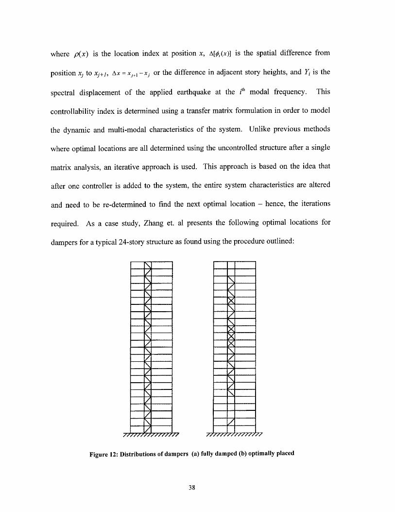
required. As a case study, Zhang et. al presents the following optimal locations for
dampers for a typical 24-story structure as found using the procedure outlined:
Figure 12: Distributions of dampers (a) fully damped (b) optimally placed

However, for practical purposes, this formulation, though simplified, may still be
too mathematically complex to be implemented into the traditional design methods.
Regardless, the overall methodology and selection process can be be understood and used
to determine damper placement. Using the dynamic computer analysis programs in a
manner described above, the locations of maximum displacement or velocity can be
determined. Once locating the first maximum displacement, the first damper may be
modeled and placed at that location and the analysis re-run. This process can then be
repeated until the desired structural response for all the floors is achieved, granted that for
very high structures this may become rather tedious.
For the design of the 57-story Chapultepec Tower in Mexico City, Mexico, the
engineers in charge of the project handled the damper placement issue slightly differently
[15]. Firstly, the underlying theory of placement is that the most efficient use of the
damper is at maximum differential velocity, rather than displacement as in the case
above. However, their approach is to increase the differential velocity experienced by the
damper for a given inter-story drift and velocity, rather than selectively placing them at
the locations of maximum differential velocity themselves. They do this by reversing the
orientation of axial velocity of the columns of the frame that the dampers are connected
to; in other words, they placed the dampers between two different lateral load resisting
systems (for the Chapultapec Tower, there are 3 different seismic systems for
redundancy). Therefore, if optimal placement with respect to which floor of the structure
the dampers should be placed is not possible, the relative velocity that a single damper
can experience can be maximized just by changing the construction configuration with

which it is placed in the building. For the Chapultapec Tower, this is done by using the
configuration shown in Figure 13, which contributes additional velocity from both
vertical and horizontal "shearing" of the building.
-- damperS structural
frame- super-structure
Figure 13: Diagram of Chapultapec Tower damperplacement configuration
In the case of a retrofit, however, there may be space or architectural limitations
that prevent the dampers to be located at their optimal location. This is usually the
controlling factor when engineers decide on damper placement. In the retrofit of the
Resources Building in Sacramento, CA, the resulting solution needed to respond to the
limitation of space as well as of the existing structural layout [11]. In this situation, the
amount of extra loading imparted to the foundations and columns were considered.
Therefore, the location and orientation of the dampers and braces were designed to
transfer the additional loads to the stronger perimeter columns - located in the Resources
Building at every third bay. As shown in Figure 14, they are also staggered in order that
the overturning moments on one floor will be counteracted in part by those from the floor
below. Here, the controlling factors in damper placement are much more practical in
40

nature. In this way, for efficient damper placement in a retrofit, the limitations of the
existing structure must also be considered. Optimal damper placement, therefore, must
take into account more than just the optimal behavior of the dampers themselves.
eTHP
T--J4~
l t4- f I I I
12
9A10 ...
?
JJ
REWVrPco# Wc).. ASMLY.TYWALnhPilYEi~i- 1 GMWERcow, 'Prftk~
Figure 14: Elevation showing damper placement in the ResourcesBuilding (Sacramento, CA)

7.0 Conclusions
The addition of fluid viscous dampers can, therefore, be seen to be a great
advantage especially in building retrofits. However, many limitations for the design firm
exist regarding their analysis and design. Although their usage has been increasing in the
past year alone with many new projects being planned, computer software limitations and
the redundancy and impracticality of academic research in this area continue to make it
difficult for the design engineer to incorporate FVDs into their buildings. Currently,
though, the structural engineers that do design with FVDs seem to have a direct
relationship with the university, some even being professors themselves. In this way, the
information and benefits regarding the use of dampers are not being disseminated into the
wider structural engineering community, but continue to remain within the academic
realm. Much collaborative and open work needs to be done in order to make the
technology of the fluid viscous damper a real option for the structural engineer. In the
same way, it is also the responsibility of the structural engineer to remain current in
his/her technical understanding of construction innovations. Going a step further, even
more collaboration needs to occur among structural engineers, researchers, software
engineers, and architects before the architectural benefits of energy dissipation devices
can be fully realized. Ultimately, the use of FVDs within buildings can be used to define
the architectural purpose of a building design, rather than just to remediate its structural
problems. This is stated best by Mies van der Rohe in his postulation about the purpose
of technology in general that:
"Whenever technology reaches its real fulfillment it transcends into architecture."

References
[1] Aguirre, M. (1997). "Earthquake-resistant structure: structural frame damper system- an approach to design." Proceedings of the Institution of Civil Engineers:Structures and Buildings, Vol. 122, May 2, 165-172
[2] Asher, J.W., Young, R.P., Ewing, R.D. (1996). "Seismic isolation design of the SanBernadino County Medical Center Replacement Project." The Structural Design ofTall Buildings, Vol. 5, 265-279.
[3] Brandow, G., Hart, G.C., Elhassan, R.M. (1996). "Seismic Rehabilitation of a TallHistoric Concrete Building by the Addition of Dampers." Proceedings of theNational Concrete and Masonry Engineering Conference III, June, 401-417.
[4] Connor, J.J., Abboud-Klink, B.S. (1996). Introduction to Motion Based Design.Computational Mechanics Publications, Boston, MA
[5] Constantinou, M.C., Symans, M.D., Taylor, D.P. (1993). "Fluid viscous damper forimproving the earthquake resistance of buildings." Structural Engineering inNatural Hazards Mitigation - Structures Congress '93, Vol. 1, 718-723.
[6] Crosby, P., Kelly, J., Singh, J.P. (1994). "Utilizing visco-elastic dampers in theseismic retrofit of a thirteen story steel framed building." Structures Congress XII,Vol. 2, 1286-1291.
[7] Haskell, G., Lee, D. (1996). "Fluid viscous damping as an alternative to baseisolation." Proceedings of the 1996 ASME Pressure Vessels and Piping Conference:
PVP Natural Hazard Phenomena and Mitigation, Vol. 330, Montreal, CAN, July 21-26, 35-40.
[8] Horr, A.M., Schmidt, L.C. (1995). "Analysis and design of tall steel structures with
added viscoelastic dampers." Structural Stability and Design - Internationalconference, Sydney, Australia, Oct. 1995, 439-446.
[9] Interim Guidelines: Evaluation, Repair, Modification and Design ofSteel MomentFrames, Report No. SAC-95-02, FEMA 267, SAC Joint Venture, Sacramento,August 1995.
[10] Jokerst, M.S., Soyer, C. (1996). "San Francisco Civic Center Complex: performancebased design with passive dampers and welded steel frames." Structural Engineers
Association of California 6 5 th Annual Convention Proceedings, Sacramento, CA,119-134.

[11] Kang, G.S. (1996). "Retrofit design with passive dampers: Resources Building,California State Building Seismic Program." Structural Engineers Association ofCalifornia 6 5 th Annual Convention Proceedings, Sacramento, CA, 183-206.
[12] Lysiak, M.P. (1996). Simplfied evaluation of seismic retrofit of inelastic structuresusing viscoelastic dampers. State University of New York at Buffalo M.S. Thesis.
[13] Miyamoto, H.K., Scholl, R.E. (1997). "Design of steel pyramid using seismicdampers." Building to Last - Proceedings of the 1997 15 th Structures Congress, Vol.2, Portland, OR, April 13-16, 1466-1470.
[14] NEHRP Guidelines for the Seismic Rehabilitation of Buildings (FEMA Publication273), Building Seismic Safety Council, ATC-33, Washington D.C., October 1997.
[15] Rahimian, A., Romero, E.M. (1998). "Chapultepec Tower Mexico City, Mexico."National AISC Steel Conference, New Orleans, April 1998.
[16] Rao, R.S., White, R.N., Gergely, P. (1995). "Retrofit of RC building frames usingfriction dampers." Restructuring: America and Beyond - Proceedings of StructuresCongress XIII, Vol. 1, Boston, MA, April 3-5, 742-745.
[17] Rasmussen, E. (1997). "Dampers hold sway." Civil Engineering, ASCE, New York,Vol. 67, No. 3, 40.
[18] Rosenbaum, D.B. (1998). "Seismic risks keep increasing." Engineering NewsRecord, (Feb. 16), 21.
[19] Shen, K.L. (1995). Viscoelastic dampers: theory, experiment and application inearthquake engineering. State University of New York at Buffalo Ph.D. Thesis.
[20] Soda, S. (1996). "Role of viscous damping in nonlinear vibration of buildingsexposed to intense ground motion." Journal of Wind Engineering and IndustrialAerodynamics, Vol. 59, Tokyo, Japan, 247-264.
[21] Whittaker, A. (Chair), Bergman, D., Clark, P., Cohen, S., Kelley, J., Scholl, R.(1993). 1993 Code Requirements for Design and Implementation ofPassive EnergyDissipation Systems, The Energy Dissipation Working Group of the Base IsolationSubcommittee of the Structural Engineers Association of Northern California, ATC-17-1, San Francisco, March.
[22] Youssef, N., Nuttall, B., Rahman, A., Hata, O. (1995). "Passive control of the LosAngeles City Hall." Proceedings of the 1995 Joint ASME/JSME Pressure Vesselsand Piping Conference: PVP Seismic, Shock, and Vibration Isolation, Vol. 319,Honolulu, HI, July 23-27, 241-248.

[23] Zhang, R., Soong, T.T. (1992) "Seismic Design of Viscoelastic Dampers forStructural Applications." Journal of Structural Engineering, ASCE, 118 (5), 1375-1392.
[24] http://www.taylordevices.com/
[25] http://www.counterquake.com/