flytec 3040 / tt34 - download.naviter.comdownload.naviter.com/flytec/archive/flytec 3040 eng...
TRANSCRIPT
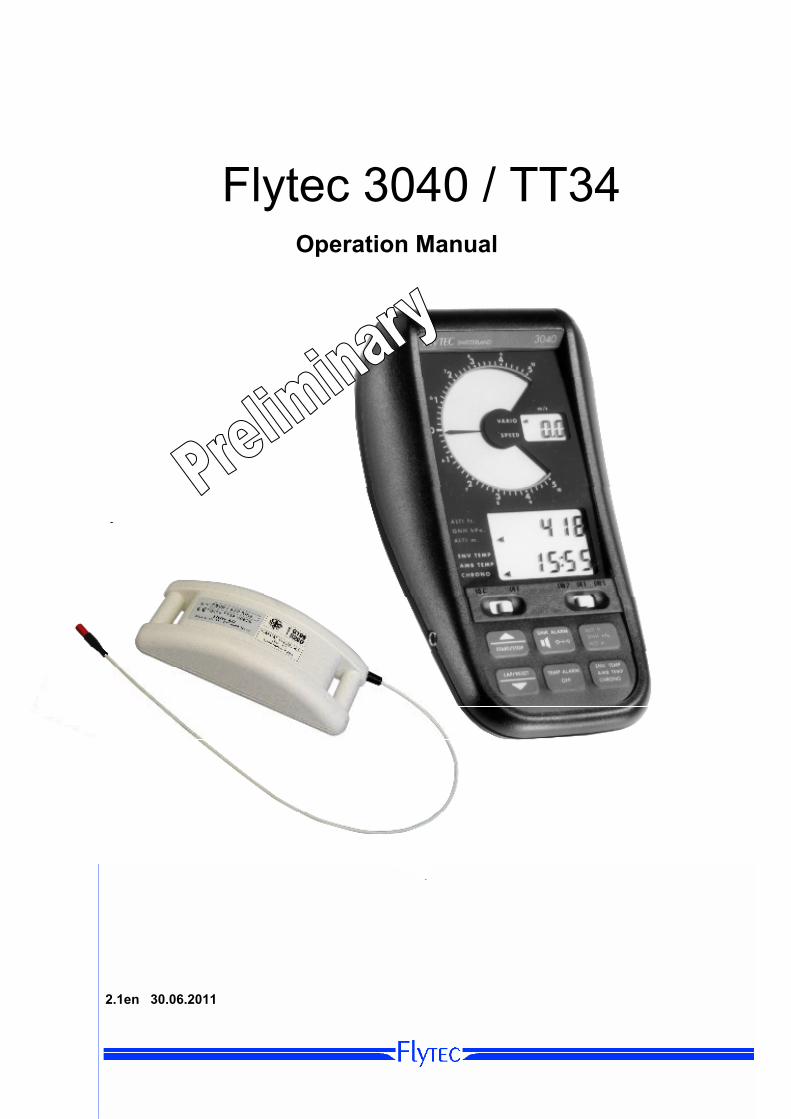
Flytec 3040 / TT34
Operation Manual 2.1en 30.06.2011
Operation manual Flytec 3040 Balloon 1
Inhaltsverzeichnis 1. Instrument overview...........................................................................................................................2 2. Operating Philosophy ........................................................................................................................3
2.1 Operating mode ...........................................................................................................................3 2.1.1 Normal flight mode................................................................................................................................. 3 2.1.2 Setting mode.......................................................................................................................................... 3 2.1.3 Configuration mode ............................................................................................................................... 4
3. Switching the instrument ON / OFF ..................................................................................................4 3.1 Switching the Instrument On........................................................................................................4 3.2 Power ON display ........................................................................................................................4 3.3 Switching the Instrument OFF .....................................................................................................4
3.3.1 By hand: ................................................................................................................................................ 4 3.3.2 Automatically switch Off:........................................................................................................................ 4
4. The Altimeter .......................................................................................................................................5 4.1 How does an altimeter work?.......................................................................................................5 4.2 Altimeter Displays ........................................................................................................................5 4.3 Altimeter Overview .......................................................................................................................6 4.4 Altimeter ALTI ft / QNH / ALTI m.................................................................................................6
4.4.1 Set Mode ALTI ft / QNH / ALTI m ........................................................................................................ 6 5. Variometer ...........................................................................................................................................7
5.1 Variometer Overview....................................................................................................................7 5.2 Analog VarioDisplay (LCD bardisplay)........................................................................................7 5.3 Digitale Vario Display ...................................................................................................................7 5.4 Sink -Akustik ...............................................................................................................................8 5.5 Set-Mode Sinkalarm.....................................................................................................................8
6. Wind speed sensor.............................................................................................................................8 7. Time functions ....................................................................................................................................9
7.1 real time clock ..............................................................................................................................9 7.2 Stop watch (Chrono) ....................................................................................................................9
8. Temperature ......................................................................................................................................10 8.1 Ambient temperatur (AMB TEMP): ............................................................................................10 8.2 Envelope Temperature (Env Temp)...........................................................................................10
8.2.1 Envelope Temperature Display (ENV TEMP)...................................................................................... 11 8.2.2 Temperature sensor failure.................................................................................................................. 11
8.3 Set mode envelope temperature ( ENV TEMP).........................................................................11 8.3.1 ID-Number ........................................................................................................................................... 11
8.4 Personal temperature alarm.......................................................................................................12 8.4.1 Set temperature alarm threshold ......................................................................................................... 12
8.5 Maximum Temp Alarm...............................................................................................................12 8.6 Deactivate envelope temperature function ................................................................................12
9. Temperature Transmitter FLYTEC TT34.........................................................................................13 9.1 Mounting TT34 ...........................................................................................................................13
10. Batteries ........................................................................................................................................14 10.1 Battery replacement ...................................................................................................................14 10.2 Changeover to rechargeable battery operation .........................................................................14
11. Maintenance..................................................................................................................................14 11.1 QNH- adjustment .......................................................................................................................15 11.2 Exposure to Water .....................................................................................................................15
12. Warranty ........................................................................................................................................15 13. Technical data...............................................................................................................................16 14. Attachment....................................................................................................................................17
14.1 Mounting instruction for the Radio Temperature Transmission Unit TT34 ................................17 14.2 QNH - correction ........................................................................................................................18 14.3 Temperature Boundary layer on a Balloon envelope ................................................................19
Operation manual Flytec 3040 Balloon 2
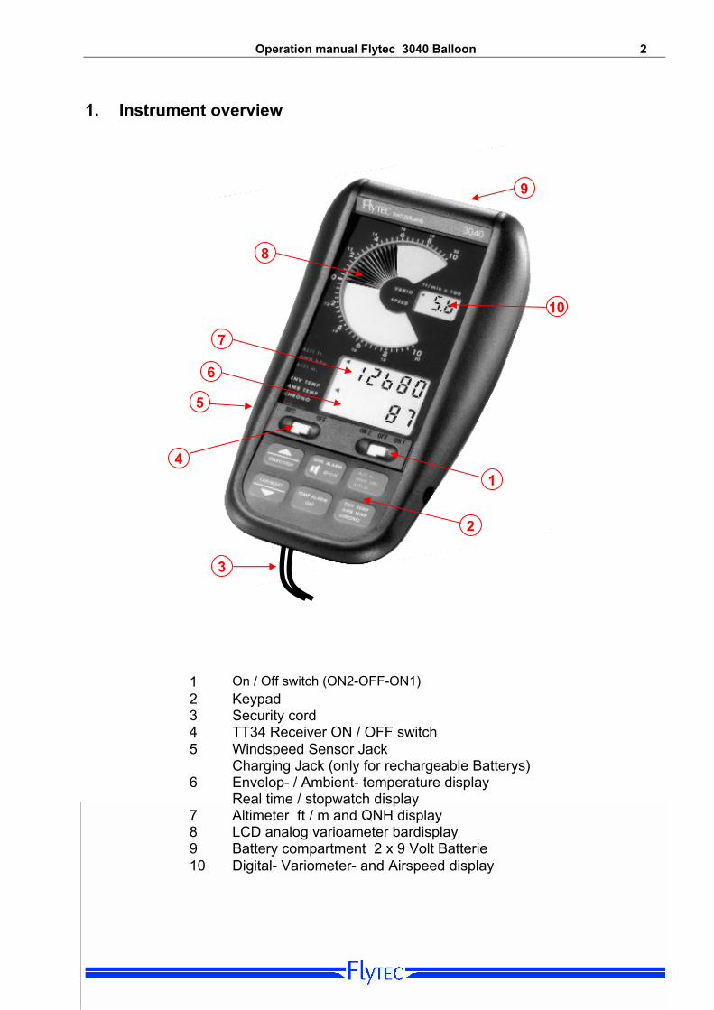
1. Instrument overview 9 8 10 7 6 5 4
1
2
3
1 On / Off switch (ON2-OFF-ON1) 2 Keypad 3 Security cord 4 TT34 Receiver ON / OFF switch 5 Windspeed Sensor Jack
Charging Jack (only for rechargeable Batterys) 6 Envelop- / Ambient- temperature display
Real time / stopwatch display 7 Altimeter ft / m and QNH display 8 LCD analog varioameter bardisplay 9 Battery compartment 2 x 9 Volt Batterie 10 Digital- Variometer- and Airspeed display
Operation manual Flytec 3040 Balloon 3
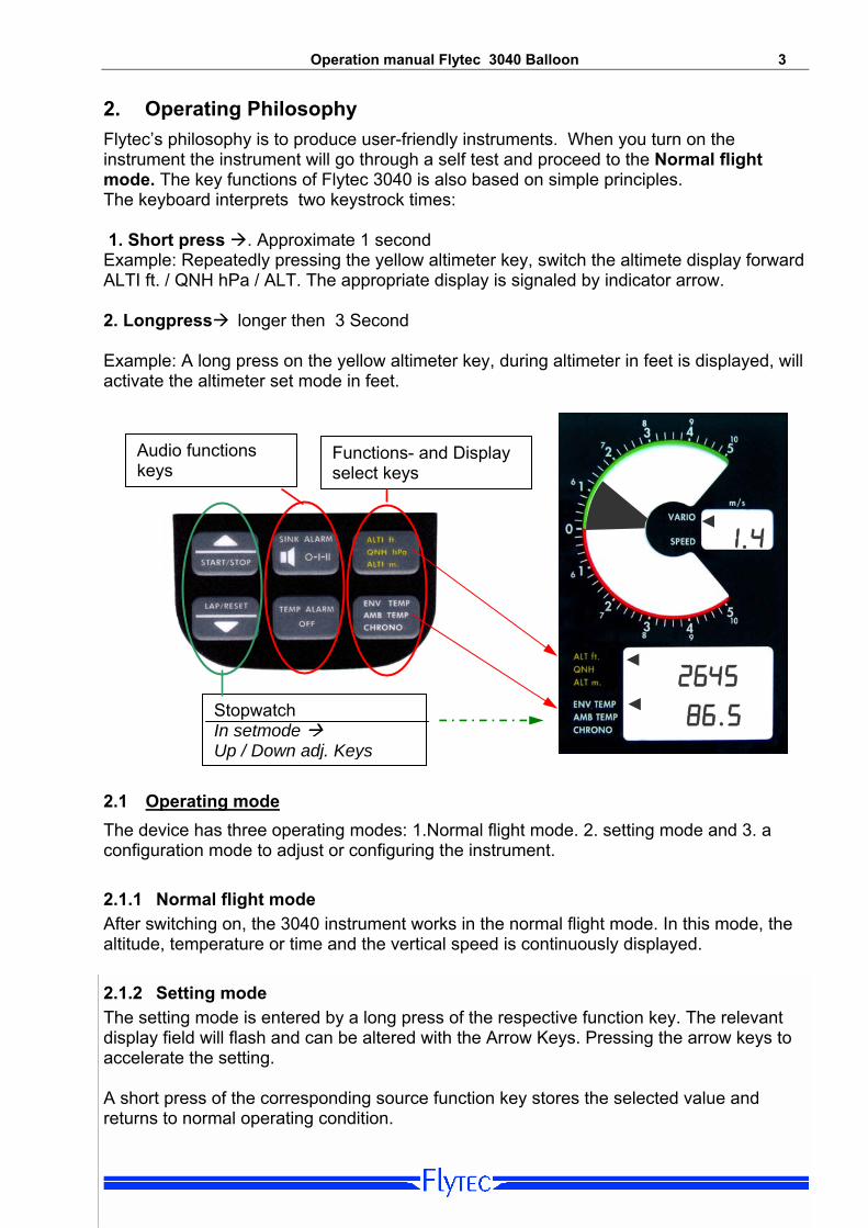
2. Operating Philosophy Flytec’s philosophy is to produce user-friendly instruments. When you turn on the instrument the instrument will go through a self test and proceed to the Normal flight mode. The key functions of Flytec 3040 is also based on simple principles. The keyboard interprets two keystrock times: 1. Short press . Approximate 1 second Example: Repeatedly pressing the yellow altimeter key, switch the altimete display forward ALTI ft. / QNH hPa / ALT. The appropriate display is signaled by indicator arrow. 2. Longpress longer then 3 Second Example: A long press on the yellow altimeter key, during altimeter in feet is displayed, will activate the altimeter set mode in feet.
86.5
◄
◄
◄ 2645
1.4
Functions- and Display select keys
Stopwatch In setmode Up / Down adj. Keys
Audio functions keys
2.1 Operating mode The device has three operating modes: 1.Normal flight mode. 2. setting mode and 3. a configuration mode to adjust or configuring the instrument. 2.1.1 Normal flight mode After switching on, the 3040 instrument works in the normal flight mode. In this mode, the altitude, temperature or time and the vertical speed is continuously displayed.
2.1.2 Setting mode The setting mode is entered by a long press of the respective function key. The relevant display field will flash and can be altered with the Arrow Keys. Pressing the arrow keys to accelerate the setting. A short press of the corresponding source function key stores the selected value and returns to normal operating condition.

Operation manual Flytec 3040 Balloon 4 2.1.3 Configuration mode This mode allows for example a QNH adjust (age deviation of the pressure sensor). This mode is accessed by pressing a specific keyboard key combination, see QNH Correction Annex page 18 .
3. Switching the instrument ON / OFF
3.1 Switching the Instrument On The 3040 unit is equipped with two independent 9V batteries. The device is switched on with the main power switch to the position ON1 or ON2 (battery 1 or battery 2)
After switching ON, the device performs a self test and displays for 10 seconds the the battery condition of the activated battery in the variometer screen.
3.2 Power ON display
The power On dispay shows the battery status, and the current time and date
18:52 hh:nn
Po
Battery status (Power) 5 = full 0 = empty
hh:mm = hours, minutes dd:mm = day, mouth YYYY = year
An insufficient batery power is indicated by lighting up of one or more segments in the red sink variometer scale. During flight, a low battery alarm appers every 5 seconds.
3.3 Switching the Instrument OFF
3.3.1 By hand:
Slide the main power switch to the center (OFF) position 3.3.2 Automatically switch Off: The 3040 will automatically power down if no flight activities (less than 25m altitude change) is detected within 30 minutes of power on. Note: For a restart, after an atomatically switch off, the main power switch must be switch to the center OFF position for at least 2 sec.
Operation manual Flytec 3040 Balloon 5
4. The Altimeter
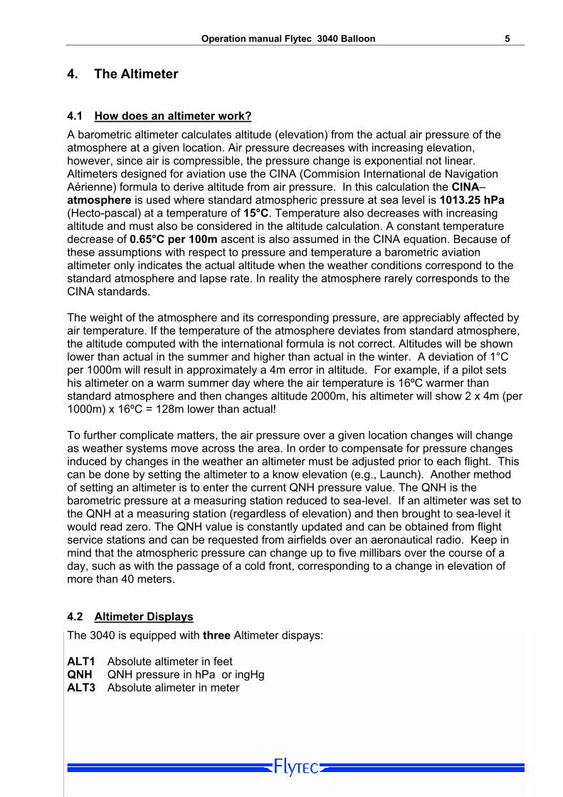
4.1 How does an altimeter work? A barometric altimeter calculates altitude (elevation) from the actual air pressure of the atmosphere at a given location. Air pressure decreases with increasing elevation, however, since air is compressible, the pressure change is exponential not linear. Altimeters designed for aviation use the CINA (Commision International de Navigation Aérienne) formula to derive altitude from air pressure. In this calculation the CINA–atmosphere is used where standard atmospheric pressure at sea level is 1013.25 hPa (Hecto-pascal) at a temperature of 15°C. Temperature also decreases with increasing altitude and must also be considered in the altitude calculation. A constant temperature decrease of 0.65°C per 100m ascent is also assumed in the CINA equation. Because of these assumptions with respect to pressure and temperature a barometric aviation altimeter only indicates the actual altitude when the weather conditions correspond to the standard atmosphere and lapse rate. In reality the atmosphere rarely corresponds to the CINA standards. The weight of the atmosphere and its corresponding pressure, are appreciably affected by air temperature. If the temperature of the atmosphere deviates from standard atmosphere, the altitude computed with the international formula is not correct. Altitudes will be shown lower than actual in the summer and higher than actual in the winter. A deviation of 1°C per 1000m will result in approximately a 4m error in altitude. For example, if a pilot sets his altimeter on a warm summer day where the air temperature is 16ºC warmer than standard atmosphere and then changes altitude 2000m, his altimeter will show 2 x 4m (per 1000m) x 16ºC = 128m lower than actual! To further complicate matters, the air pressure over a given location changes will change as weather systems move across the area. In order to compensate for pressure changes induced by changes in the weather an altimeter must be adjusted prior to each flight. This can be done by setting the altimeter to a know elevation (e.g., Launch). Another method of setting an altimeter is to enter the current QNH pressure value. The QNH is the barometric pressure at a measuring station reduced to sea-level. If an altimeter was set to the QNH at a measuring station (regardless of elevation) and then brought to sea-level it would read zero. The QNH value is constantly updated and can be obtained from flight service stations and can be requested from airfields over an aeronautical radio. Keep in mind that the atmospheric pressure can change up to five millibars over the course of a day, such as with the passage of a cold front, corresponding to a change in elevation of more than 40 meters.
4.2 Altimeter Displays The 3040 is equipped with three Altimeter dispays: ALT1 Absolute altimeter in feet QNH QNH pressure in hPa or ingHg ALT3 Absolute alimeter in meter
Operation manual Flytec 3040 Balloon 6
4.3 Altimeter Overview 1s 3s 1s
Exit set mode
Key Function Set
Mode
ALT ft Altitude adjust feet
QNH QNH adjust
ALT m Altitude adjust
meter
ALTI ft QNH hpa ALTI m
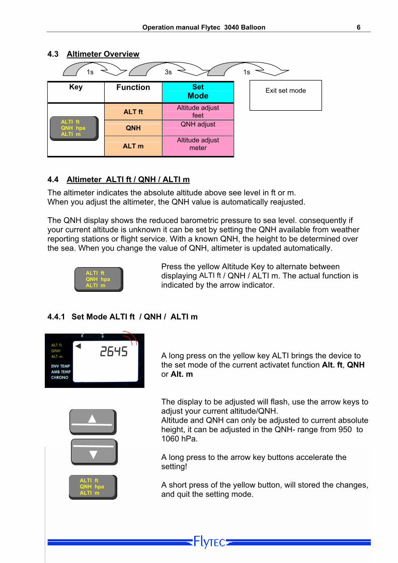
4.4 Altimeter ALTI ft / QNH / ALTI m The altimeter indicates the absolute altitude above see level in ft or m. When you adjust the altimeter, the QNH value is automatically reajusted. The QNH display shows the reduced barometric pressure to sea level. consequently if your current altitude is unknown it can be set by setting the QNH available from weather reporting stations or flight service. With a known QNH, the height to be determined over the sea. When you change the value of QNH, altimeter is updated automatically.
Press the yellow Altitude Key to alternate between displaying ALTI ft / QNH / ALTI m. The actual function is indicated by the arrow indicator.
ALTI ft QNH hpa ALTI m
4.4.1 Set Mode ALTI ft / QNH / ALTI m
. ◄
2645 A long press on the yellow key ALTI brings the device to the set mode of the current activatet function Alt. ft, QNH or Alt. m The display to be adjusted will flash, use the arrow keys to adjust your current altitude/QNH. Altitude and QNH can only be adjusted to current absolute height, it can be adjusted in the QNH- range from 950 to 1060 hPa.
▼
▲
A long press to the arrow key buttons accelerate the setting!
ALTI ft QNH hpa ALTI m
A short press of the yellow button, will stored the changes, and quit the setting mode.

Operation manual Flytec 3040 Balloon 7 5. Variometer The variometer displays the vertical speed and informs the pilot about the actual climb or sink rate . The sink rate is also indicated by an acoustric sound.
5.1 Variometer Overview
Key Acoustic Volume Set
Volume Off Level 1, 2
Sink Allarm
3s 1s 1s
SINK ALARM
- O-I-II
Exit to normal mode
5.2 Analog VarioDisplay (LCD bardisplay) Each graduation on the analog bar scale equals 20 cm/s. Up to 5 m/s, the bar fills up from the center. When your climb rate exceeds 5 m/s the climb is displayed in reverse – that is, the display at 5 m/s is full and it begins to clear from the middle, as in the illustration below. Sample: Climb rate
1.8 m/s Climb rate at 7.2 m/s
Climb rate at 5 m/s
◄1.8
◄ 5.0
◄ 7.2
5.3 Digitale Vario Display The digital vario display shows the ascent or descent-rate with a resolution of 0.1 m / s over the entire measuring range.
Operation manual Flytec 3040 Balloon 8
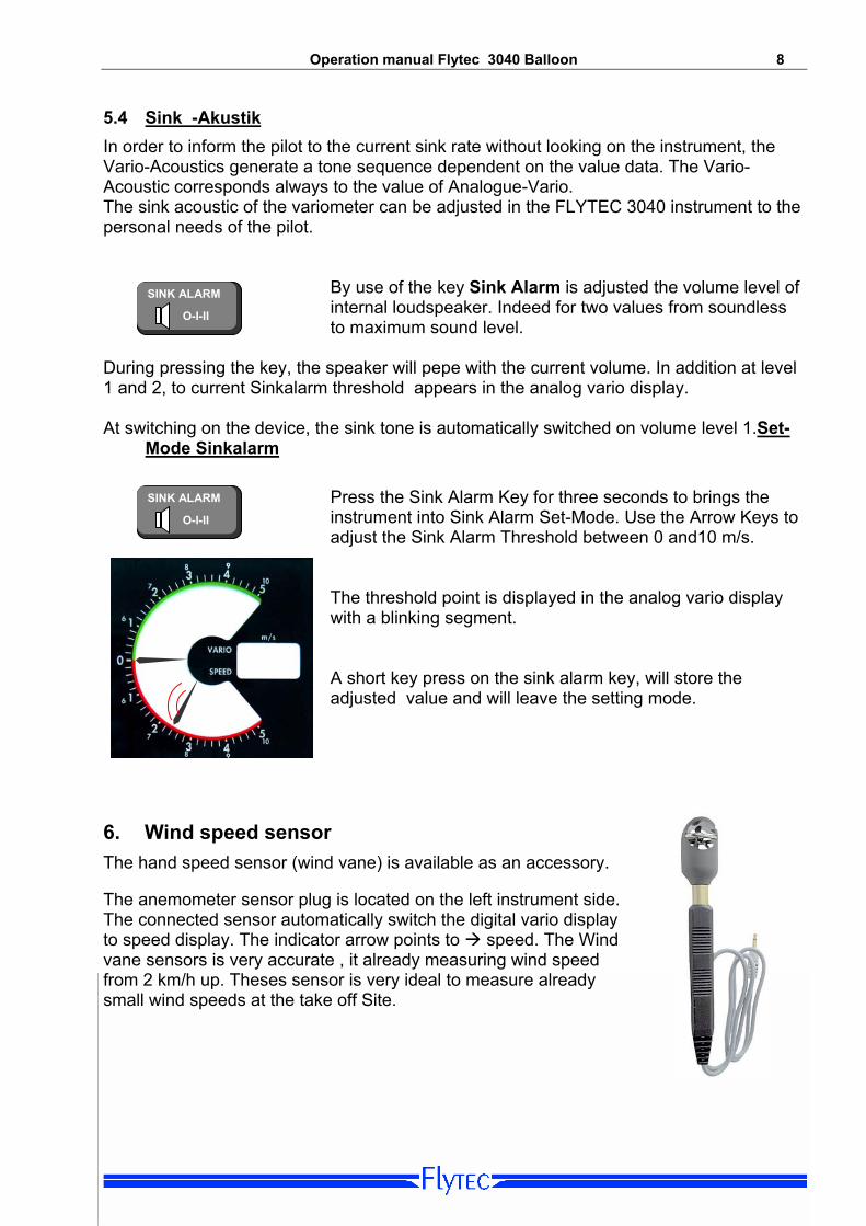
5.4 Sink -Akustik In order to inform the pilot to the current sink rate without looking on the instrument, the Vario-Acoustics generate a tone sequence dependent on the value data. The Vario-Acoustic corresponds always to the value of Analogue-Vario. The sink acoustic of the variometer can be adjusted in the FLYTEC 3040 instrument to the personal needs of the pilot.
By use of the key Sink Alarm is adjusted the volume level of internal loudspeaker. Indeed for two values from soundless to maximum sound level.
SINK ALARM
- O-I-II
During pressing the key, the speaker will pepe with the current volume. In addition at level 1 and 2, to current Sinkalarm threshold appears in the analog vario display. At switching on the device, the sink tone is automatically switched on volume level 1.Set-
Mode Sinkalarm
Press the Sink Alarm Key for three seconds to brings the instrument into Sink Alarm Set-Mode. Use the Arrow Keys to adjust the Sink Alarm Threshold between 0 and10 m/s.
SINK ALARM
- O-I-II
The threshold point is displayed in the analog vario display with a blinking segment. A short key press on the sink alarm key, will store the adjusted value and will leave the setting mode.
6. Wind speed sensor The hand speed sensor (wind vane) is available as an accessory. The anemometer sensor plug is located on the left instrument side. The connected sensor automatically switch the digital vario display to speed display. The indicator arrow points to speed. The Wind vane sensors is very accurate , it already measuring wind speed from 2 km/h up. Theses sensor is very ideal to measure already small wind speeds at the take off Site.

Operation manual Flytec 3040 Balloon 9
7. Time functions This unit has two time functions: a real-time clock, and a stopwatch
The change between the three functions in the bottom display can be done with a short press of the button CHRONO The activated time display appears with the indicator arrow on Chrono.
ENV TEMP AMB TEMP CHRONO
7.1 real time clock RTC: If the indicator arrow points to CHRONO, the Real-time is displayed in the lower display field. Note: When the stopwatch is activited, the stopwatch time instead real-time is displayed. Set mode time: Pressing the Chrono Key for three seconds, enter the instrument into Time-Set-Mode.
1. In the top display hh:mm appears. In the bottom display the current time hours and minutes flashes. Changehouers and minutes with the Up or Down key. Confirm the correct input by pressing the button Chrono.
16:25 ◄
◄
2645
ENV TEMP AMB TEMP CHRONO
16:25 ◄
◄
2645 2. In the top display dd:mm appears. In the bottom display the current time hours and minutes flashes. Change day and mounts with the Up or Down key. Confirm the correct input by pressing the button Chrono.
3. The last setting is the year (YYYY) . 4. Pressing the button Chrono will store the time seting and
also leave the setting mode
7.2 Stop watch (Chrono) The stopwatch can by activated by pressing the Start / Stop key. A running stopwatch is indicated with a flashing arrow, the arrow stays steadily when the Chrono is stopped.
Pressing the LAP button frezes the display and allowing the elapse time to that point to be read, pressing the LAB key a second time, switches the display back to the runing stopwatch. During the LAP-time is diplayed, the time is still continues running in the background. By pressing the STOP button, the current time measurement is stopped and started by pressing the button again. This function can be determined to messure the exact flight time, non flight times (such as stopovers) can be excreted. Pressing the Reset key (when the clock is stopt), reset the stopwatch to zero, and will automatically switch back to real time display. Note: The stopwatch functions can be used at any time, even the display shows the temperatur!

Operation manual Flytec 3040 Balloon 10
8. Temperature
8.1 Ambient temperatur (AMB TEMP): The FLYTEC 3040 is provided with a temperature sensor inside of the housing for the temperature compensation of pressure sensors, this Ambient temperature is displayed in the lower display when the Arrow is pointed to AMB TEMP Notice: the temperature sensor measures the internal circuit board temperature, and not directly the outside air temperature! The inside temperature of the housing may be higher or lower than the ambient air temperature, especially when the instrument is exposed to direct sunlight.
8.2 Envelope Temperature (Env Temp) The envelope temperature is being transmitted by radio to the radio transmission unit TT34 (Option). The TT34 radio transmission unit is being switched on automatically by an active envelope temperature, and is being switched off automatically if the envelope is not being used any more. The temperature sensor transmits its data in a cycle of four seconds. During a balloon event where you find many balloons close to each other the TT34 does not interferes with each other. In order to avoid interferences each TT34 has an individual identity number (ID), which is being transmitted with the radio protocol. The 3040 instruments only accepts radio dates, which are identical with the ID-number registrated in the 3040 instrument.
Note: A received signal with an invalid ID-number is being indicated as „ID“ in the display field ENV TEMP
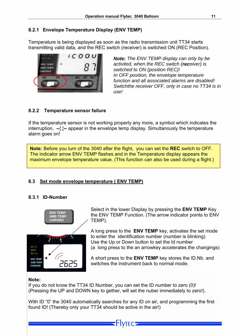
Operation manual Flytec 3040 Balloon 11 8.2.1 Envelope Temperature Display (ENV TEMP) Temperature is being displayed as soon as the radio transmission unit TT34 starts transmitting valid data, and the REC switch (receiver) is switched ON (REC Position).
Note: The ENV TEMP display can only by be activited, when the REC switch (receiver) is switched to ON (position REC)! In OFF position, the envelope temperature function and all associated alarms are disabled! Switchthe receiver OFF, only in case no TT34 is in use!
8.2.2 Temperature sensor failure If the temperature sensor is not working properly any more, a symbol which indicates the interruption, --¦ ¦-- appear in the envelope temp display. Simultanously the temperature alarm goes on!
Note: Before you turn of the 3040 after the flight, you can set the REC switch to OFF. The indicator arrow ENV TEMP flashes and in the Temperature display appears the maximum envelope temperature value. (This function can also be used during a flight.)
8.3 Set mode envelope temperature ( ENV TEMP) 8.3.1 ID-Number
Select in the lower Display by pressing the ENV TEMP Key the ENV TEMP Function. (The arrow indicator points to ENV TEMP).
ENV TEMP AMB TEMP CHRONO
A long press to the ENV TEMP key, activates the set mode to enter the identification number (number is blinking)
2625 ◄
Use the Up or Down button to set the Id number (a long press to the an arrowkey accelerates the changings) A short press to the ENV TEMP key stores the ID.Nb. and switches the instrument back to normal mode.
Note: If you do not know the TT34 ID Number, you can set the ID number to zero (0)! (Pressing the UP and DOWN key to gether, will set the nuber immediately to zero!). With ID “0” the 3040 automatically searches for any ID on air, and programming the first found ID! (Thereby only your TT34 should be active in the air!)
Operation manual Flytec 3040 Balloon 12
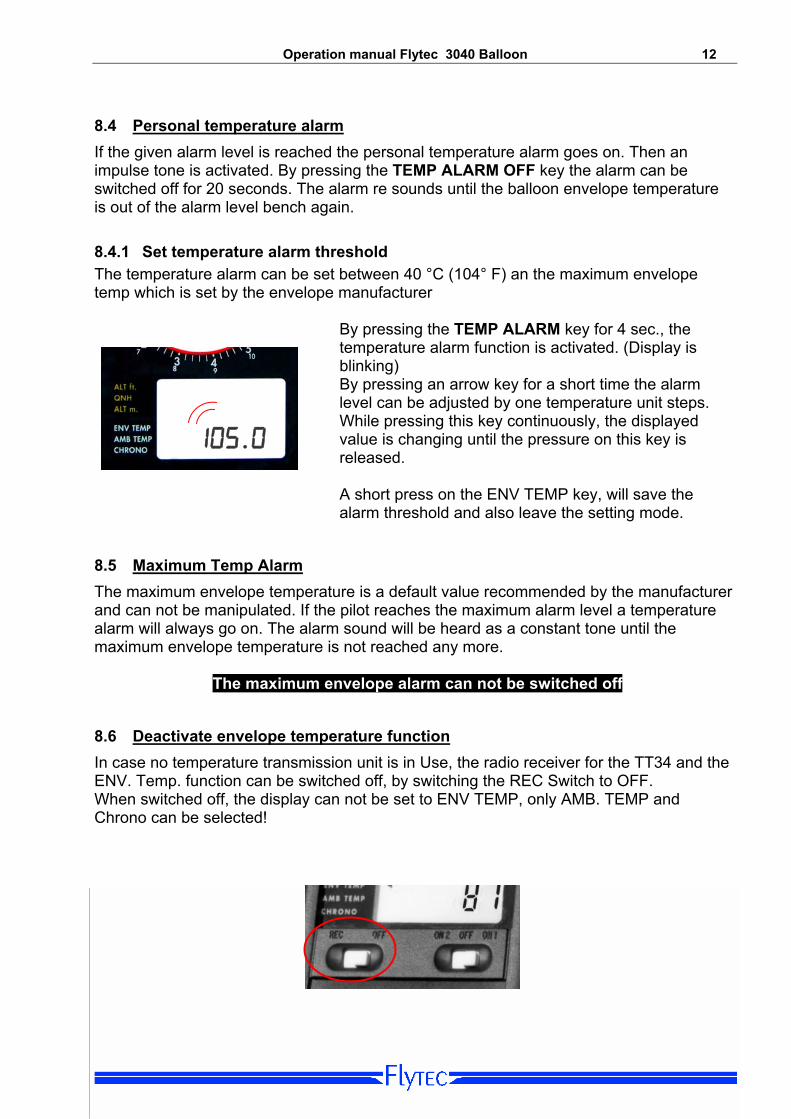
8.4 Personal temperature alarm If the given alarm level is reached the personal temperature alarm goes on. Then an impulse tone is activated. By pressing the TEMP ALARM OFF key the alarm can be switched off for 20 seconds. The alarm re sounds until the balloon envelope temperature is out of the alarm level bench again. 8.4.1 Set temperature alarm threshold The temperature alarm can be set between 40 °C (104° F) an the maximum envelope temp which is set by the envelope manufacturer
By pressing the TEMP ALARM key for 4 sec., the temperature alarm function is activated. (Display is blinking)
105.0
By pressing an arrow key for a short time the alarm level can be adjusted by one temperature unit steps. While pressing this key continuously, the displayed value is changing until the pressure on this key is released. A short press on the ENV TEMP key, will save the alarm threshold and also leave the setting mode.
8.5 Maximum Temp Alarm The maximum envelope temperature is a default value recommended by the manufacturer and can not be manipulated. If the pilot reaches the maximum alarm level a temperature alarm will always go on. The alarm sound will be heard as a constant tone until the maximum envelope temperature is not reached any more.
The maximum envelope alarm can not be switched off
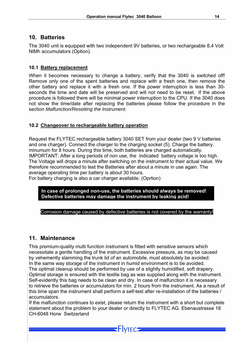
8.6 Deactivate envelope temperature function In case no temperature transmission unit is in Use, the radio receiver for the TT34 and the ENV. Temp. function can be switched off, by switching the REC Switch to OFF. When switched off, the display can not be set to ENV TEMP, only AMB. TEMP and Chrono can be selected!

Operation manual Flytec 3040 Balloon 13
9. Temperature Transmitter FLYTEC TT34 The radio transmission unit TTT34 is operating with a 9-V battery. The temperature transmission is switched on automatically as soon as the differential temperature between the instrument and the envelope temperature (factory default value) is being recognized by the TT34 unit. . Switch on: Differential temperature of > 15ºC or abs. > 50ºC Switch off: Differential temperature of < 15ºC and abs. < 50ºC The operation time fort the Alcaline-battery lasts for about 3 years and with a full operation time of around 200 hours. We recommend, to change the battery at every 2 annual Envelope maintenance.
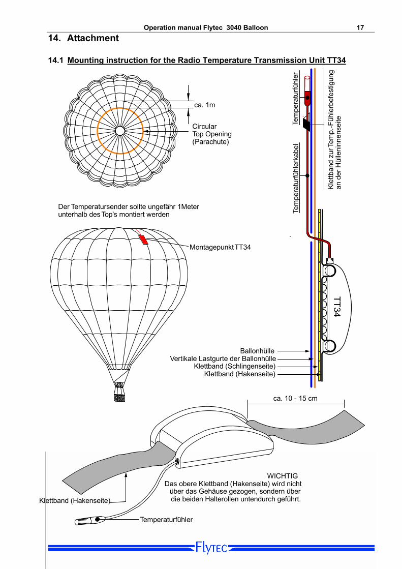
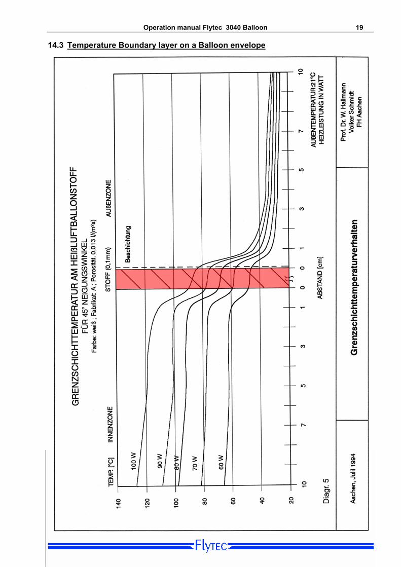
9.1 Mounting TT34 The TT34 unit is mounted on the outside of the envelop. The temperature sensor must be laid to the inner side of the envelope and must be solidly mounted in a way that he touches the envelope tissue. Improper installation will result in incorrect temperature readings! Temperature sensors who have no contact with the fabrics will messure a wrong temperature. The temperature of the hot air, drops or rises inside or otside of the envelope in a distance of only 1 cm (boundary layer) strongly! Depending on the mounting position it can quickly result in an temperature error of 10-20 ˚C ! Note the graphic thermal boundary layer over the balloon fabric in the appendix on page 18
The mounting must be carried out exactly according to the regulation. (See attachment on page 17)
Operation manual Flytec 3040 Balloon 14
10. Batteries The 3040 unit is equipped with two independent 9V batteries, or two rechargeable 8,4 Volt NiMh accumulators (Option).
10.1 Battery replacement When it becomes necessary to change a battery, verify that the 3040 is switched off! Remove only one of the spent batteries and replace with a fresh one, then remove the other battery and replace it with a fresh one. If the power interruption is less than 30-seconds the time and date will be preserved and will not need to be reset. If the above procedure is followed there will be minimal power interruption to the CPU. If the 3040 does not show the time/date after replacing the batteries please follow the procedure in the section Malfunction/Resetting the Instrument.
10.2 Changeover to rechargeable battery operation Request the FLYTEC rechargeable battery 3040 SET from your dealer (two 9 V batteries and one charger). Connect the charger to the charging socket (5). Charge the battery. minumum for 8 hours. During this time, both batteries are charged automatically. IMPORTANT: After a long periods of non use, the indicated battery voltage is too high. The Voltage will drops a minute after switching on the instrument to their actual value. We therefore recommended to test the Batteries after about a minute in use again. The average operating time per battery is about 30 hours. For battery charging is also a car charger available. (Oprtion)
In case of prolonged non-use, the batteries should always be removed! Defective batteries may damage the instrument by leaking acid!
Corrosion damage caused by defective batteries is not covered by the warranty!
11. Maintenance
This premium-quality multi function instrument is fitted with sensitive sensors which necessitate a gentle handling of the instrument. Excessive pressure, as may be caused by vehemently slamming the trunk lid of an automobile, must absolutely be avoided. In the same way storage of the instrument in humid environment is to be avoided. The optimal cleanup should be performed by use of a slightly humidified, soft drapery. Optimal storage is ensured with the textile bag as was supplied along with the instrument. Self-evidently this bag needs to be clean and dry. In case of malfunction it is necessary to retrieve the batteries or accumulators for min. 2 hours from the instrument. As a result of this time span the instrument shall perform a self-test after re-installation of the batteries / accumulators. If the malfunction continues to exist, please return the instrument with a short but complete statement about the problem to your dealer or directly to FLYTEC AG. Ebenaustrasse 18 CH-6048 Horw Switzerland
Operation manual Flytec 3040 Balloon 15
11.1 QNH- adjustment Pressure Senore aging can change altitude relation to QNH. A recalibration can be made in the Option-Modes; however, the correction values for these functions should only be altered for good reason (i.e. you are sure that the displayed values are inaccurate). For calibration intruction see Appendix.
11.2 Exposure to Water If the instrument was immersed under water or was exposed to water ingress, the batteries need to be removed immediately in order to prevent a destructive short-circuit. In the case of salt water, rinse the instrument and all parts affected by the salt water with clean, hand-hot soft water in order to avoid corrosion. Thereafter dry the instrument carefully by blowing warm air of max. + 60 °C (hair dryer). Never place the instrument into a microwave-stove! Microwaves shall destroy the instrument immediately! After complete drying please return imperatively the instrument to your dealer or directly to FLYTEC AG for final check over. Any claim under Warranty is void after a water landing.
12. Warranty FLYTEC AG provides the warranty that this instrument does not carry any material or manufacturing defect for the period of two years from the moment of its first purchase. The warranty extends to manufacturing defects and failures for which the owner is not responsible. The warranty will become invalid in case of inappropriate handling or exposure of the instrument to strong heat or water and also when unauthorised manipulations to the inner parts of the instrument have been effected. If defects should occur within the two-years warranty period, please contact your dealer from whom you have purchased the instrument, or contact directly the manufacturer, FLYTEC AG, Switzerland. Please study this Operation Manual carefully and to its entire content. Please do it anyway at the latest before asking questions or presenting complaints to the dealer or manufacturer. Disclaimer of Warranty:
Technische Daten
In rare cases it might not be excluded that the instrument does not provide any data at all or incorrect data. In regard to the legal fact that it is solely the pilot who has the responsibility of performance of his flights, the Company FLYTEC AG shall reject any claim on damage resulting from data loss or wrong data of your instrument.
Operation manual Flytec 3040 Balloon 16
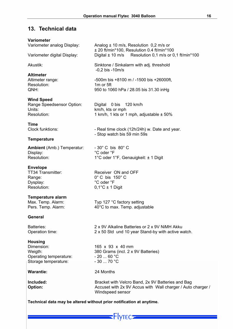
13. Technical data Variometer Variometer analog Display: Analog ± 10 m/s, Resolution 0,2 m/s or ± 20 ft/min*100, Resulution 0.4 ft/min*100 Variometer digital Display: Digital ± 10 m/s Resolution 0,1 m/s or 0,1 ft/min*100 Akustik: Sinktone / Sinkalarm with adj. threshold -0,2 bis -10m/s Altimeter Altimeter range: -500m bis +8100 m / -1500 bis +26000ft, Resolution: 1m or 5ft QNH: 950 to 1060 hPa / 28.05 bis 31.30 inHg Wind Speed Range Speedsensor Option: Digital 0 bis 120 km/h Units: km/h, kts or mph Resolution: 1 km/h, 1 kts or 1 mph, adjustable ± 50% Time Clock funktions: - Real time clock (12h/24h) w. Date and year.
- Stop watch bis 59 min 59s Temperature Ambient (Amb.) Temperatur: - 30° C bis 80° C Display: °C oder °F Resolution: 1°C oder 1°F, Genauigkeit: ± 1 Digit Envelope TT34 Transmitter: Receiver ON and OFF Range: 0° C bis 150° C Dysplay: °C oder °F Resolution: 0,1°C ± 1 Digit Temperature alarm Max. Temp. Alarm: Typ 127 °C factory setting Pers. Temp. Alarm: 40°C to max. Temp. adjustable General Batteries: 2 x 9V Alkaline Batteries or 2 x 9V NiMH Akku Operation time: 2 x 50 Std und 10 year Stand-by with active watch. Housing Dimension: 165 x 93 x 40 mm Weigth: 380 Grams (incl. 2 x 9V Batteries) Operating temperature: - 20 ... 60 °C Storage temperature: - 30 ... 70 °C Warantie: 24 Months Included: Bracket with Velcro Band, 2x 9V Batteries and Bag Option: Accuset with 2x 9V Accus with Wall charger / Auto charger / Windspeed sensor Technical data may be altered without prior notification at anytime.
Operation manual Flytec 3040 Balloon 17 14. Attachment
TT34
ca. 1m
BallonhülleVertikale Lastgurte der Ballonhülle
Klettband (Schlingenseite)Klettband (Hakenseite)
MontagepunktTT34
CircularTop Opening(Parachute)
Klettband (Hakenseite)
Temperaturfühler
Der Temperatursender sollte ungefähr 1Meterunterhalb desTop's montiert werden
WICHTIGDas obere Klettband (Hakenseite) wird nicht
über das Gehäuse gezogen, sondern überdie beiden Halterollen untendurch geführt.
ca. 10 - 15 cm
Tem
pera
turfü
hler
kabe
lTe
mpe
ratu
rfühl
er
Klet
tban
d zu
rTem
p.-F
ühle
rbef
estig
ung
an d
er H
ülle
ninn
ense
ite
14.1 Mounting instruction for the Radio Temperature Transmission Unit TT34
Operation manual Flytec 3040 Balloon 18
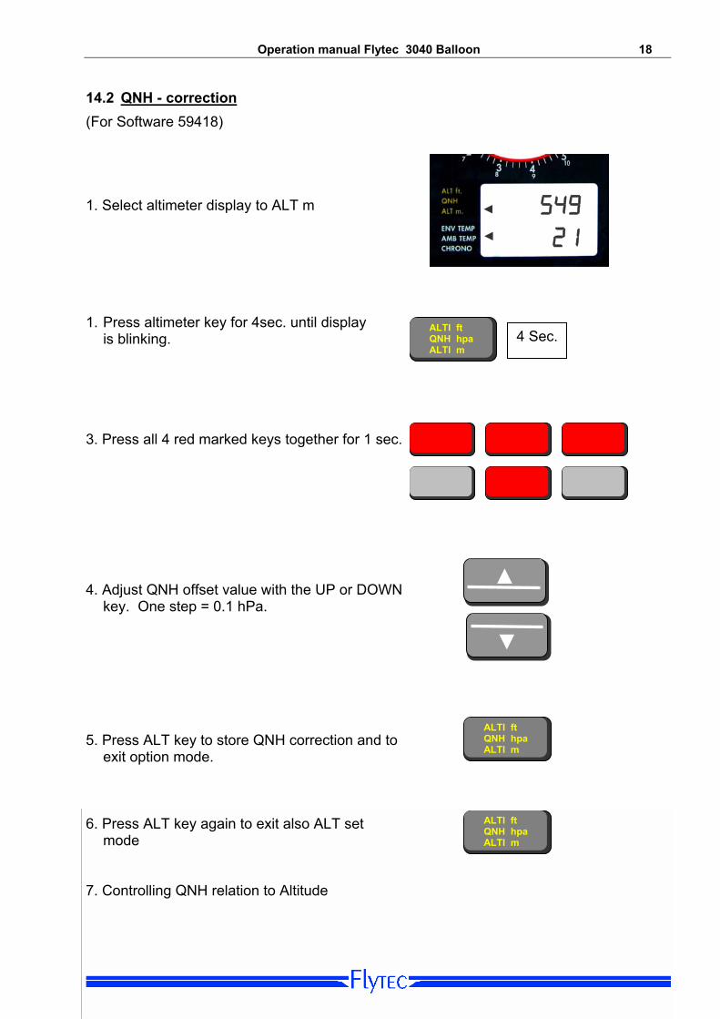
14.2 QNH - correction (For Software 59418)
21 ◄
◄ 549 1. Select altimeter display to ALT m 1. Press altimeter key for 4sec. until display ALTI ft
QNH hpa ALTI m
4 Sec. is blinking.
3. Press all 4 red marked keys together for 1 sec.
▼
▲ 4. Adjust QNH offset value with the UP or DOWN
key. One step = 0.1 hPa. ALTI ft
QNH hpa 5. Press ALT key to store QNH correction and to exit option mode. ALTI m
ALTI ft QNH hpa 6. Press ALT key again to exit also ALT set
mode ALTI m 7. Controlling QNH relation to Altitude
Operation manual Flytec 3040 Balloon 19
14.3 Temperature Boundary layer on a Balloon envelope