for design, installation and seismic restraint of
TRANSCRIPT

CODE OF PRACTICEFor Design, Installation and Seismic Restraint of Suspended Ceilings
OCTOBER 2015
The purpose of this Code of Practice is to assist the construction industry, building
consent authorities, architects, engineers, builders, installers and specifiers to comply
with the New Zealand Building Code.

ASSOCIATION OF WALL AND CEILING INDUSTRIES OF NEW ZEALAND INC.The Association of Wall and Ceiling Industries of New Zealand Inc. is a grouping of building industry
organisations, including contractors, tradespeople, manufacturers and suppliers, established to
represent the interests of members and their customers for interior wall and ceiling lining systems and
related products.
The Association was formed in 1992 as the Interior Systems Association incorporating existing trade
groups of suspended ceilings, plasterboard and fibrous plaster. The name of the association was
changed in November 2005.
AWCINZ membership is open to any interested party.
For further information, please contact [email protected] or go to www.awcinz.org.nz.
DOCUMENT HISTORYThis document may be updated from time to time. Refer to the website www.awcinz.org.nz for the
most recent updates of this Code of Practice:
Version Date Amendments
1st published edition October 2015
Comments on this Code of Practice are welcome, please send all comments to [email protected].
The production of this Code of Practice was funded by BRANZ whose support is gratefully
acknowledged. Responsibility for the content lies solely with the Association of Wall and Ceiling
Industries of New Zealand and does not necessarily reflect the opinion of BRANZ.
AWCINZ – CODE OF PRACTICE – For Design, Installation and Seismic Restraint of Suspended Ceilings
ACKNOWLEDGEMENTThis Code of Practice was prepared by a project team comprising:
Ruth Berry – BRANZ
Keith Hogg – Hush Interiors Limited
John Keen – USG Boral
John Parkin – AWCI NZ
Dennis Prout – Forman/Rondo

1AWCINZ – CODE OF PRACTICE – For Design, Installation and Seismic Restraint of Suspended Ceilings
Foreword
FOREWORD FROM THE MINISTRY OF BUSINESS INNOVATION AND EMPLOYMENT
Damage to suspended ceilings from recent
earthquakes has highlighted the need for correct
design and installation of ceilings and other non-
structural parts of buildings, such as partitions
and building services. The failure of non-
structural elements in an earthquake can injure
or kill people and can prevent the uninterrupted
use of buildings after an earthquake.
This new Code of Practice focuses on seismic
restraints and separations for suspended
ceilings and on the roles and responsibilities
of those involved to ensure that suspended
ceilings are designed and installed correctly.
The co-ordination with designers and
contractors working on other non-structural
elements is also highlighted.
The Ministry congratulates the Association of
Wall and Ceiling Industries on its initiative in
producing this Code of Practice. It is encouraging
to see industry groups creating their own
guidance and codes of practice to complement
Ministry guidance and Acceptable Solutions
and Verification Methods. Note, however, that
this Code of Practice is not part of the Ministry’s
Acceptable Solutions, Verification Methods or
guidance documents.
Improving the compliance and performance
of suspended ceilings will rely on greater
awareness of responsibilities for design
and installation from those involved in the
construction industry. To this end, we hope that
this Code of Practice will assist the industry
with the procurement, design and installation of
suspended ceilings.

2 AWCINZ – CODE OF PRACTICE – For Design, Installation and Seismic Restraint of Suspended Ceilings
Contents1 Introduction 6
Possible reasons for failure of suspended ceilings 6
2 Background 8
Past industry practice 8
The challenge for the industry 8
3 AWCI seismic grade 10
Identifying the AWCI seismic grade of a ceiling 10
Cost considerations 11
4 Design 12
The design process 12
Roles and responsibilities of the parties involved in the design 12
Design co-ordination 14
Other trades in the plenum 14
Seismic restraint of non-structural building components other than ceilings 14
Who does the design for other building components? 14
Co-ordination of design 14
5 Design documentation 16
Compliance with NZBC and standards 16
Seismic design 16
Perimeter fixing 17
Seismic forces 17
Braced ceilings 17
Classification of parts (P2–P7) 18
Building importance level 18
6 Ceiling types and components 21
Ceiling fixing methods 21
Ceiling systems 21
Two-way exposed 21
One-way exposed 22
Fully concealed 23
Plasterboard or other sheet-lined suspension systems 24
Specialty or feature ceilings 25
Linear and metal 26
Curved ceilings 27
Floating cloud 28
Ceilings below other ceilings 28
Wind loads 29
Bulkheads 30
Ceiling components 33
Wall trims and perimeter channels 33
Fixing clips 34
Main tees 35
Cross tees 36
7 Testing of product 37
8 Manufacturers’ generic seismic design guides 38
9 Specific engineering design (SED) 39
10 Generic details 40
Seismic separation joint details 40
Lateral force bracing 43
Perimeter restraint 44
Fixed-end options 45
Non-fixed-end options 48
Tile clips 49
Hangers 49
Bridging 50
Trapeze 51
11 Possible reasons for and consequences of failure 52
12 Tendering 54
Options for tendering 54
Option 1: Where tender documents include full details of seismic restraints 54

3AWCINZ – CODE OF PRACTICE – For Design, Installation and Seismic Restraint of Suspended Ceilings
Model tender qualification where seismic restraints are fully detailed 54
Option 2: Where seismic restraint design is required to be carried out at construction stage 55
Model tender qualification where seismic restraints are not detailed in tender documents 55
Option 3: Specific engineering design 55
Model tender qualification where specific engineering design is required 56
General tender qualifications 56
Tender, consent and shop drawings 56
13 Installation 57
Site inspection 57
Material storage and handling 57
Pre-installation checklist 57
Facilities for installation of suspended ceilings 57
Best-practice co-ordination with other ceiling services 58
Installation details to seismic design 58
Aesthetics 58
Specialty tools 58
Quality assurance 58
Inspection 59
Refurbishment work 59
14 Partitions 60
15 Fire and suspended ceilings 62
Passive fire 62
16 Acoustics 63
Sound absorption (NRC) 63
Sound transmission (STC, CAC) 63
17 Monitoring design and construction 65
Producer statements 65
Design producer statement (PS1) 65
Design review producer statement (PS2) 65
Construction producer statement (PS3) 66
Construction review producer statement (PS4) 66
Construction monitoring (CM) levels 66
Level CM2 66
Level CM3 66
Level CM4 66
18 Summary of roles and responsibilities 67
Designer 67
Ceiling tenderer 67
Installer 67
Building consent authority 68
Appendices 69
A. Definitions, abbreviations and notations 69 B. Relevant standards and associated documents 73
C. Tendering options guidelines 74
D. Installer’s producer statement (PS3) template 77
E. Sample QA sheet 78
F. Design information list 79
4 AWCINZ – CODE OF PRACTICE – For Design, Installation and Seismic Restraint of Suspended Ceilings
Figures and tablesTable 1: AWCI seismic grades for suspended ceilings 11
Figure 1: Change in relative cost of seismic requirements as complexity increases 11
Figure 2: Recommended project process 13
Table 2: Main steps and parties that may be involved 15
Table 3: Definitions 15
Figure 3: Seismic layout concepts 17
Table 4: Classification of building parts 18
Table 5: Building importance levels 19
Figure 4: Exposed grid and tile system in place 21
Figure 5: Schematic diagram of two-way grid 21
Figure 6: Concealed edge 22
Figure 7: Tee grid visible in only one direction 22
Figure 8: Schematic diagram of one-way exposed grid 22
Figure 9: Back-to-back L splines 23
Figure 10: C and Z splines 23
Figure 11: Tee grid 23
Figure 12: Concealed grid 23
Figure 13: Suspended sheeted or flush ceiling grid system 24
Figure 14: Direct fix sheeted or flush ceiling system 24
Figure 15: Finished feature ceilings 25
Figure 16: Suspended linear or strip ceiling system 26
Figure 17: Curved ceiling schematic 27
Figure 18: Proprietary linear ceiling system 27
Figure 19: Floating cloud ceilings 28
Figure 20: Feature ceiling below another ceiling 28
Figure 21: Wind loads 29
Figure 22: Bulkhead off solid underfloor 30
Figure 23: Bulkhead off solid underfloor with two ceilings at different heights 30
Figure 24: Suspended ceiling and bulkhead, cantilevered top ceiling support 31
Figure 25: Suspended ceiling and bulkhead 31
Figure 26: Suspended ceiling and light trough bulkhead 32
Figure 27: Suspended ceiling to blind box detail 32
Figure 28: L trims, various sizes, equal and unequal leg length 33
Figure 29: Shadow trims, various sizes 33
Figure 30: C channels, various sizes 33
Figure 31: Wall shims, used at edges of ceilings to accommodate sloped ceilings 33
Figure 32: Perimeter clips 34
Figure 33: Main beam joint clip 34
Figure 34: Cross tee joint clip 34
Figure 35: Three-way cross joint clip for off- module connection 34
Figure 36: Main tee, 24 mm face 35
Figure 37: Fire-rated main tee, 24 mm face 35
Figure 38: Main tee, 15 mm face 35
Figure 39: Cross tee, 24 mm face 36
Figure 40: Cross tee, 15 mm face 36
Figure 41: Seismic separation joints shown in both directions 40
Figure 42: Small seismic joint, two directions, hidden joint 41
Figure 43: Small seismic joint, one direction, hidden joint 41
Figure 44: Seismic joint clip – main beam 41
Figure 45: Seismic joint clip – cross tee 41
Figure 46: Large seismic joint with concave cover strip 42
Figure 47: Large seismic joint with cover strip at bottom of T-rail 42
Figure 48: Large seismic joint with cover strip above T-rail 42

5AWCINZ – CODE OF PRACTICE – For Design, Installation and Seismic Restraint of Suspended Ceilings
Figure 49: Lateral force bracing using solid struts 43
Figure 50: Lateral force bracing using splayed wires 43
Figure 51: Generic wall clip 44
Figure 52: Proprietary perimeter restraint components, component in place with rails 44
Figure 53: Pop rivet 45
Figure 54: Pop rivet with spacer block (used with rebated tiles) 45
Figure 55: Seismic clip – main or cross tee 46
Figure 56: Seismic clip – cross tee with spacer block 46
Figure 57: Seismic clip – main or cross tee with spacer block and shadow wall angle 47
Figure 58: Seismic clip – wall angle and wall angle with spacer block 48
Figure 59: Seismic channel 48
Figure 60: Hanger wire minimum tie-off 49
Figure 61: Bridging under ducts or services by other trades 50
Figure 62: Typical trapeze 51
Figure 63: Trapeze wire detail 51
Figure 64: Lack of suspension points and service clearance 52
Figure 65: Unbraced partitions and service ducts 52
Figure 66: Sprinkler system supported from ceiling componentry rather than suspended as it should be 52
Figure 67: The result of an unbraced ceiling 53
Figure 68: Damage to ceiling tile from an unrestrained fire protection system 53
Figure 69: Damage caused by unrestrained services 53
Figure 70: Lack of suspension points 53
Figure 71: Proprietary internal wall bracing connection (isolated from ceiling movement) 60
Figure 72: Generic internal wall bracing connection – wall terminates at ceiling 60
Figure 73: Generic internal wall bracing connection – wall terminates above ceiling 61
Figure 74: Horizontal bracing 61
Figure 75: Sound reflection 63
Figure 76: Sound transmission 64
Table 6: Producer statements likely to be required according to seismic grade 65

6 AWCINZ – CODE OF PRACTICE – For Design, Installation and Seismic Restraint of Suspended Ceilings
Introduction
Despite the requirements of various New
Zealand standards,1 the seismic compliance
of ceilings has received scant attention in
recent years. A series of major earthquakes in
Christchurch in 2010 and 2011 and in Seddon in
2013, which also affected Wellington, highlighted
a systemic problem.
Many ceilings, partitions and building services
within ceiling voids collapsed, causing damage in
commercial and institutional buildings. In some
cases, poorly restrained ceilings failed along
with the building services they were supporting,
and in others, ceilings were compromised
by unrestrained or poorly restrained building
services and partitions. Overseas, there are
examples in Japan and California where injury
and loss of life have occurred as a result of
ceilings and/or building services they were
supporting failing.
According to a University of Canterbury report,2
well over half of the costs incurred in the
Christchurch earthquakes were associated
with non-structural elements such as ceilings,
partitions and services. The Insurance Council
of New Zealand reported to a Parliamentary
Select Committee in May 2014 that the cost of
non-structural element failures had resulted
in many otherwise repairable buildings being
demolished.3
Aside from the obvious concerns about the
safety of building occupants and widespread
non-compliance with the New Zealand Building
Code (NZBC), these avoidable losses are a
significant burden on the New Zealand economy.
The industry is under increasing pressure to
assure seismic compliance on current and future
construction projects.
POSSIBLE REASONS FOR FAILURE OF SUSPENDED CEILINGS
There are many reasons for possible failure
of the suspended ceiling, including but not
limited to:
y the seismic performance of the building
y unsuitable ceiling design for the particular
structure
y the use of an unsuitable product/system
y installation not meeting the requirements
of either the manufacturer, supplier or the
NZBC
y ceiling hangers not installed correctly
y services within the ceiling space or
connected to the ceiling grid not installed to
current codes
y perimeter walls or bulkheads insufficient to
receive the live loads of a ceiling
y insufficient seismic gaps to allow for
movement of the building structure
y partitions being connected to the ceiling
system but not independently braced
y a lighter gauge of ceiling grid or non-tested
system being installed outside its non-
structural capability
y interference from other non-structural
building components in the plenum.
1
7AWCINZ – CODE OF PRACTICE – For Design, Installation and Seismic Restraint of Suspended Ceilings
This Code of Practice covers suspended
ceilings only and highlights the need for
effective co-ordination of the ceiling support
and restraint systems with seismic restraints
for the specialist building services installations
whose requirements are governed by separate
standards.
AWCINZ expects that the adoption of this
Code of Practice – and the transition to fully
compliant ceilings – will improve safety and
reduce economic losses due to the failure of
non-structural components.
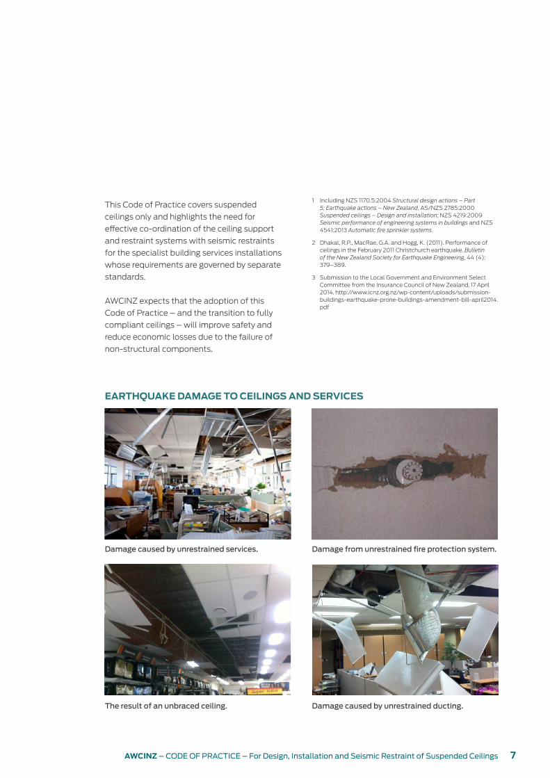
Damage caused by unrestrained services.
The result of an unbraced ceiling.
Damage from unrestrained fire protection system.
Damage caused by unrestrained ducting.
1 Including NZS 1170.5:2004 Structural design actions – Part 5: Earthquake actions – New Zealand, AS/NZS 2785:2000 Suspended ceilings – Design and installation; NZS 4219:2009 Seismic performance of engineering systems in buildings and NZS 4541:2013 Automatic fire sprinkler systems.
2 Dhakal, R.P., MacRae, G.A. and Hogg, K. (2011). Performance of ceilings in the February 2011 Christchurch earthquake. Bulletin of the New Zealand Society for Earthquake Engineering, 44 (4): 379–389.
3 Submission to the Local Government and Environment Select Committee from the Insurance Council of New Zealand, 17 April 2014. http://www.icnz.org.nz/wp-content/uploads/submission-buildings-earthquake-prone-buildings-amendment-bill-april2014.pdf
EARTHQUAKE DAMAGE TO CEILINGS AND SERVICES

8 AWCINZ – CODE OF PRACTICE – For Design, Installation and Seismic Restraint of Suspended Ceilings
Background
PAST INDUSTRY PRACTICE
In many cases, the design for seismic restraint
of suspended ceilings has been an afterthought
or not done at all. The scope of the seismic
restraints and related engineering work required
has also often not been known until the ceiling
design has been completed. A typical approach
has been as follows:
y Architects and engineers seldom provide all
necessary technical information required to
design the seismic restraints for a particular
building at the time of tendering. Tenders
are based on specifications and reflected
ceiling plans. The suspended ceiling
contractor works with the main contractor
to agree aesthetic details such as edge trim,
bulkheads, seismic breaks, trimming for light
fittings and grilles and service tiles. Shop
drawings are provided only where required to
clarify details.
y Ceiling hangers are set out with hangers at
the spacings required for the gravity support
of the selected ceiling system. Often, they
are cut or moved by other trades to allow
building services to be installed, or services are
installed without the clear spacing required
under NZS 4219:2009.
y Product-specific seismic design and
installation guides available from key industry
manufacturers and suppliers offer a range of
generic details, but they do not eliminate the
need for the structural engineering design to
achieve and demonstrate seismic compliance.
A structural engineer may inspect the work to
decide where seismic restraints and braces
can be fitted to achieve the required level of
seismic design detail.
In addition, a market driven by the lowest
tender price provides little incentive to properly
address seismic restraints at budget and
tender stage. A suspended ceiling contractor
who allows for a seismically compliant
ceiling is unlikely to win against lower-priced
competitors who ‘tag out’ seismic restraints,
allow a nominal provisional sum or overlook
the matter completely.
A persistent failure to address the matter as an
early-stage design issue has resulted in non-
conforming ceilings, avoidable rework, financial
losses and disputes. Rectification of issues
associated with ceilings that have inadequate
seismic restraint costs ceiling contractors in
terms of additional work required due to lack of
co-ordination of non-structural components,
disputes and potential litigation should the
ceiling subsequently fail.
THE CHALLENGE FOR THE INDUSTRYAt the time of tender, a number of factors need
to be known (for a comprehensive list, see
Appendix F):
y Location of the building
y Building importance level
y Parts category (from NZS 1170.5:2004
section 8)
y Annual probability of exceedance (return
period)
y AWCI seismic grade
y A set of relevant working drawings
y Height of the ceiling seismic attachment from
ground level
y Seismic mass (including weights of linings,
insulation and service load provisions)
y Wind load.
Regardless of past industry practice, it is
not acceptable to treat seismic restraints
and related structural engineering design,
monitoring and certification as if they were
optional. The industry must therefore revisit
its practices in the procurement of buildings
and in the methodology of all stages of design
and construction to assure compliance with
minimal added cost.
2

9AWCINZ – CODE OF PRACTICE – For Design, Installation and Seismic Restraint of Suspended Ceilings
The industry needs to change the way it designs,
procures, installs and certifies suspended
ceilings and co-ordinates the seismic design
details with other building elements.
The AWCINZ challenge to industry is to ensure
that seismic design of suspended ceilings and
building services is addressed in a co-ordinated
manner, at the earliest possible stage of design,
before tenders are called, which will reduce
uncertainty, define the scope of work and allow
tenderers to provide a firm price for the ceiling
system. Leaving the seismic design details until
later creates risk and uncertainty for all.
At time of tender, the information below may
also be required:
y How the building structure has been designed
to perform in an earthquake event.
y How the ceiling supports and restraints may
be co-ordinated with the structure.
y The space that will be available in the ceiling
void for seismic restraints.
y How ceiling supports and restraints will be
co-ordinated with the building services to be
installed in the ceiling void for which detailed
shop drawings have not yet been produced.
y The cost of engaging a qualified structural
engineer with specialist knowledge of
suspended ceilings to design and certify the
design of the seismic restraints for each area
of ceiling.
y The type and extent of seismic restraints that
will be required by the structural engineer and
consequently their cost.
y The cost of engaging the specialist structural
engineer to monitor installation work
(including the number of inspections required
by the main contractor’s construction
programme) and to certify the completed
installation.
This challenge cannot be met by the suspended
ceilings industry alone. As there is no ‘standard’
building, there can be no ‘standard’ seismic
restraints solution. Most buildings involve
extensive specialist architectural, geological,
structural and services engineering and require
specific design input to address their site,
location, form and function.
A cost-effective and compliant solution is
possible with a co-ordinated approach to design
and procurement.

10 AWCINZ – CODE OF PRACTICE – For Design, Installation and Seismic Restraint of Suspended Ceilings
In order to make the process of achieving a
compliant ceiling system understandable to
the wider industry, AWCINZ has established
a seismic grading system for use at the early
design stage.
Adopting a seismic grade allows designers
to identify the extent to which a suspended
ceiling is able to resist seismic forces and/or
to remain intact in the event of an earthquake.
The seismic grade applies to each ceiling, and
it is conceivable that certain ceilings within a
building will have a higher seismic grade than
other ceilings in that building.
Each step up from the basic AWCI seismic grade
1 ceiling to the highest AWCI seismic grade
4 ceiling reflects an incremental step in grid
strength, shop drawing requirements, the type
and extent of seismic restraint, the requirement
for specific engineering design and the
involvement of independent seismic specialists.
There are a number of standards that are
relevant to seismic restraints.
AS/NZS 2785:2000 Suspended ceilings –
Design and installation
This standard sets out minimum requirements
for the design, construction, installation,
maintenance and testing of internal and external
non-trafficable suspended ceiling systems of dry
construction with suspension systems attached
to a supporting structure, for use in commercial,
industrial and residential applications. It includes
earthquake design requirements for ultimate limit
state (ULS) and serviceability limit state (SLS)
and when and where earthquake loads should be
considered, by reference to NZS 1170.5:2004.
NZS 1170.5:2004 Structural design actions –
Part 5: Earthquake actions – New Zealand
This standard provides procedures for
the determination of earthquake actions
on structures in New Zealand. It gives the
requirements for verification procedures, site
hazard determination, the evaluation of structural
characteristics, structural analysis for earthquake
action effects, the determination and limits for
deformations and the seismic design of parts of
structures. It is to be applied in conjunction with
AS/NZS 1170 parts 0, 1, 2 and 3 relevant material
standards.
NZS 4219:2009 Seismic performance of
engineering systems in buildings (services
only)
This standard sets out the criteria for the seismic
performance of engineering systems related
to a building’s function. It covers the design,
construction and installation of seismic restraints
for these engineering systems. Buildings with
importance level 5, large mass items, structures
external to the building, lifts, building contents
and fire sprinkler systems are excluded from this
standard.
IDENTIFYING THE AWCI SEISMIC GRADE OF A CEILINGThe first step in establishing the seismic
grade of a ceiling (or ceilings) is to identify
the geological, functional and engineering
attributes, features or design factors that are
relevant for the particular ceiling with regard to
the requirements of the relevant New Zealand
standards or other requirements.
The seismic grade of each ceiling is to be
determined by the highest-scoring seismic grade
(AWCI SG1 = lowest seismic grade, AWCI SG4 =
highest seismic grade) based on the information
available.
The ceiling designer will need to make
conservative assumptions about the site subsoil
category, building and ceiling risk category,
building and ceiling ductility and period of
vibration based on the information supplied.
AWCI seismic grade3

11AWCINZ – CODE OF PRACTICE – For Design, Installation and Seismic Restraint of Suspended Ceilings
Additional information such as geotechnical
reports or structural calculations for the building
may allow for a more economical design, if these
are available.
Ceiling seismic grades are set out in Table 1.
COST CONSIDERATIONSAt the time of tendering, the actual requirements
for each ceiling, having regard to its designated
seismic grade and the requirements of the
tender documents, should be checked.
Table 1: AWCI seismic grades for suspended ceilings.
Seismic grade Description
AWCI SG1 y Ceiling in a building with low seismic performance requirements with ceiling
component category P7 and SLS1 (up to building importance level 3).
y Not requiring specific engineering design.
AWCI SG2 y Ceiling in a building with low seismic performance requirements with ceiling
component category P7 and SLS1 (up to building importance level 3).
y Within design parameters of relevant manufacturers’ standard type-tested designs
but not requiring specific engineering design.
y PS3 with supporting documents.
AWCI SG3 y Ceiling in a building up to building importance level 3 or component category P4
where ceilings must be designed for ULS, in public spaces, forming part of an
emergency egress way, supporting life safety systems or at high level.
y May be within design parameters of relevant manufacturers’ standard type-tested
designs, but specific engineering design is required.
y Minimum of PS1 and PS3 with supporting documents.
AWCI SG4 y Ceiling in a building up to building importance level 4 or component category P4
where ceilings must be designed for ULS, in public spaces, forming part of an
emergency egress way, supporting life safety systems or at high level.
y Specific engineering design is required.
y Minimum of PS1, PS3 with supporting documents and PS4.
Figure 1: Change in relative cost of seismic requirements as complexity increases.
Figure 1 demonstrates the incremental
steps in the relative complexity and extent
of engineering design and monitoring and
consequentially the relative cost implications
of the various seismic grades.
While compliance with NZBC seismic
requirements can add cost, it will also limit
damage, reduce repair costs, reduce the length of
time for reoccupancy after a seismic event and
minimise health and safety risks for occupants.
Relative cost of ceiling grade
Extent of seismic restraints, engineering
design, monitoring and certification
SG1
Low
High
SG2 SG3 SG4
AWCI seismic grades

12 AWCINZ – CODE OF PRACTICE – For Design, Installation and Seismic Restraint of Suspended Ceilings
CONSTRUCTION PRODUCER STATEMENT (PS3)
A PS3 is certification from the suspended
ceiling contractor that the ceiling has been
installed in accordance with the relevant
design, New Zealand standards and/or building
consent as applicable.
Lead designers, BCAs, owners and insurers
should be aware of the limitations of
manufacturers’ generic guidelines and
assumptions made, for example, the
structure(s) that the bracing points a ceiling is
fixed to must be adequate to take the load.
It is important to note that, for retrofit/
refurbishment, the lead designer needs to
provide sufficient information on the structural
detail, including loading capacity, of the building.
While, in some cases, actual product systems
are specified by the designer, they can also be
specified on a performance basis, leaving the
tenderer free to offer whichever system they feel is
able to meet the requirements. Further, the design
of non-structural building elements often occurs
after the building consent has been granted.
The seismic bracing system for these non-
structural building elements is thus typically
the responsibility of the contractor and their
subcontractors.
Figure 2 shows a recommended project process
from design to completed installation of a
suspended ceiling system. Some steps may not
be relevant for all projects. See Section 17, p65
for detail on producer statements.
ROLES AND RESPONSIBILITIES OF THE PARTIES INVOLVED IN THE DESIGNIn most construction projects, there are many
parties involved. All have different roles and
THE DESIGN PROCESS
The opportunity to get the best design outcome
is greatest early in the design process.
While the final product selection may not
be known, the design parameters of all non-
structural building elements should be outlined
as early as possible so that all subcontractors
are aware of the other trades.
The lead designer should be responsible for
co-ordinating the design and installation of all
subtrade equipment in the plenum and ceiling.
The preferred approach, to ensure optimal co-
ordination and productive use of resources, is for
seismic design of non-structural components
to be completed prior to the project going out
to tender. Where a construction phase design
process is used, the lead designer needs to
specify the seismic grade of the ceiling and the
associated seismic restraint requirements in the
tender documents.
Ideally, construction documents should be
delivered with a PS1 for the suspended ceiling
design. This would show that the ceiling has been
designed to the minimum structural requirements.
DESIGN PRODUCER STATEMENT (PS1)A PS1 is a statement of opinion that certain
aspects of proposed building work will comply
with the NZBC if the work is constructed
according to the referenced documentation
(for example, engineering design drawings and
specifications).
The seismic design of suspended ceilings
should be undertaken by a suitably qualified
person with experience in ceiling design. If a
manufacturer’s generic seismic design guide is
used, the working sheets should be submitted
with the PS3.
Design4

13AWCINZ – CODE OF PRACTICE – For Design, Installation and Seismic Restraint of Suspended Ceilings
Figure 2: Recommended project process.
Start
BIL 1 BIL 2 BIL 3 BIL 4 BIL 5Determine building importance level
Celling complexity, change in height or plane, height above FGL, building components >10kg, other trades, access
Consider other factors (including but not limited to)
Design method
Designer’s/specialistdesigner’s responsibilities
Tenderer’s responsibilities
BCA’s responsibilities (at consent application)
Installer’s responsibilities
Designer, specialist designer, engineer
BCA compliance
Use manufacturers’ generic design guides
Designed by a suitably qualified person
A: Design ceiling and appropriate seismic restraintsB: Co-ordinate with other trades/design professionalsC: Issue a PS1 if requiredD: Commission a PS2 if required.
A: Ensure all details workB: Ensure all seismic restraints workC: Tag out any issues arisingD: Review co-ordination with other trades
A: Review consent documents for NZBC compliance including the design of seismic restraints where detailed
A: Visually inspect site before commencing any workB: Raise any issues arising with project manager before commencing workC: Issue PS3 if required
A: Review installation for conformance with consented drawings
A: Issue PS4 if required
A: Issue Code Compliance Certificate
End

14 AWCINZ – CODE OF PRACTICE – For Design, Installation and Seismic Restraint of Suspended Ceilings
responsibilities, and in many steps of the
process, the roles and responsibilities of several
parties will overlap.
Table 2 shows, in general, the main steps in
construction projects, the main parties involved
and the stages where input from each party may
be required. Table 3 defines the key roles involved.
DESIGN CO-ORDINATIONMany view a suspended ceiling as a finished
surface only and are unaware of the potential
complexity of the design in the plenum.
Consequently, they may not be aware of the
possible true cost of a suspended ceiling
system that has been designed to withstand
earthquake actions.
Designers of other components in the plenum
may have little regard to requirements of the
ceiling support system.
The ceiling tenderer needs to establish what
degree of co-ordination has taken place between
the other suppliers of building components in
the plenum in terms of their design, engineering
calculations and installation processes.
Design co-ordination is possibly the single
biggest issue facing suspended ceiling work. In
general, the better co-ordination prior to issuing
tender documents:
y the more accurate a costing can be achieved
y the better the installation process will be
y there will be fewer site variations
y there will be an overall lower total cost
y there will be fewer time delays during
installation
y there will be fewer site conflicts.
OTHER TRADES IN THE PLENUMSeismic restraint of non-structural building
components other than ceilings
It is an NZBC requirement that non-structural
building components must be properly
restrained against earthquake actions to prevent
them collapsing on people, cutting off exit routes
from the building, being damaged or damaging
other property.
The seismic design and compliance of building
components in the plenum space are the
responsibility of their respective designer, with
the most common way of meeting the NZBC
requirements being the use of Verification
Method B1/VM1.
B1/VM1 cites New Zealand standard NZS
4219:2009, which contains prescriptive
and specific engineering design options for
restraining engineering systems, including items
interrelated with suspended ceilings.
There are a wide range of non-structural
building components that can be located in the
plenum or below, including but not limited to:
y sprinkler systems
y air-conditioning ducts
y cabling ducts
y lighting systems, including their support
y ceiling-height partition walls
y bracing for ceiling-height partition walls
y full-height partition walls
y mechanical installations for access
y telecommunications cabling
y office equipment suspended from the ceiling
system, for example, overhead projectors,
security cameras, ceiling fans, alarm systems,
air-conditioner cassettes, drop-down
projector screens, signage, speakers and fire
alarm systems.
Who does the design for other building
components?
The layout of building components in the
plenum needs to be co-ordinated so that any
one component does not impede or interfere
with another, for example:
y the need to allow 25 mm free movement
around sprinkler droppers can be eliminated
by using flexible hose droppers
y careful consideration is required to ensure that
elements such as light fittings and diffusers
supported by the ceiling are independently
supported unless under allowable weight
limits – refer to relevant standards.
Co-ordination of design
Ideally, the lead designer should be responsible for
co-ordinating non-structural building components
in the plenum so that there are no conflicts.
Checklist to complete before tender shall include:
y bracing layout
y edge details
y services
y proof of co-ordination and location of services
y suspended ceiling plan overlaid with services
and plenum
y suspension points identified that are clear of
services
y unrestrained/restrained services
y maximum lateral displacement.

15AWCINZ – CODE OF PRACTICE – For Design, Installation and Seismic Restraint of Suspended Ceilings
Table 2: Main steps and parties that may be involved.
Design Compliance design
Tendering Contract Installation Completion
Client 3 3 3
Project manager 3 3 3 3 3
Lead designer 3 3 3 3 3
Specialist designer 3 3 3 3 3
Engineer 3 3 3 3
Main contractor 3 3 3 3 3 3
Suspended ceiling contractor 3 3 3 3 3 3
Other trades 3 3 3 3 3 3
Supplier 3 3 3 3
Building consent authority 3 3 3
Table 3: Definitions.
Client The entity parties are contracted to.
Project manager A person or company who will have an overview of the whole project, which may include co-ordination of the design team.
Lead designer May be an architect, interior designer or engineer. The lead designer oversees the entire documentation process. Historically, this has been an architect, but more recently and depending on the nature of the project, other suitably qualified people have been taking on this role.
Specialist designer
Each component in the plenum may have their own specialist designer.
Engineer A suitably qualified structural engineer.
Main contractor The company that has contracted to build the entire project and is responsible for overseeing and co-ordinating all on-site trades and the construction programme.
Suspended ceiling contractor
The company that will be carrying out the installation and, in some circumstances, installation design.
Other trades Other trades that may have non-structural building components being installed in the plenum such as air-conditioning ducts, fire protection systems or lighting fixtures.
Supplier The company supplying the product for installation.
Building consent authority
Where required, the organisation that will grant a building consent, carry out inspections as necessary and, at completion, issue a Code Compliance Certificate.

16 AWCINZ – CODE OF PRACTICE – For Design, Installation and Seismic Restraint of Suspended Ceilings
The design and construction of a successful
building requires the successful integration of
a range of inputs, with one key factor being
that the construction documentation must
be well co-ordinated. Design documents
provide the critical link between all parties in a
building project so that everyone knows what
is being built, where it is being put, when it will
be done and how it is done. The better the
documentation, the better the outcome will be.
With respect to suspended ceilings and all
components and services in the plenum, design
documentation should:
y clearly define design parameters and
responsibilities from the outset and
communicate these to all parties involved in
the project
y enable everyone to identify anything that may
impact on their part of the project
y give consistent information and specify critical
datum point measurements – for suspended
ceilings, the set-out point and design criteria
are critical
y show where other components in the plenum
will be located and their fixing points – 3D
schematics would help to show any issues
that may arise at the points of intersection
y specify the co-ordination of the installation
sequencing.
The use of technology such as building
information modelling (BIM) should also be
considered.
COMPLIANCE WITH NZBC AND STANDARDSNZBC clause B1 Structure requires that all building
elements must have a low probability of failure
when exposed to loads likely to be experienced
within their lifetime. Compliance with the NZBC
can be achieved through Acceptable Solutions,
Verification Methods or using Alternative Solutions.
There are no published Acceptable Solutions for
Design documentation
suspended ceilings, and therefore Verification
Methods are almost always used.
Verification Method B1/VM1 provides a means
for the design of structures to meet the
performance requirements of NZBC clause B1
Structure. Within B1/VM1, there are numerous
standards referenced that relate to suspended
ceilings and engineering systems likely to be
encountered in any building.
For engineering systems and non-structural
building components, the most common
Verification Methods for earthquake restraint are:
y NZS 4219:2009 Seismic performance of
engineering systems in buildings
y NZS 1170.5:2004 Structural design actions –
Part 5: Earthquake actions – New Zealand and
the relevant product standard, for example,
AS/NZS 2785:2000 Suspended ceilings –
Design and installation or NZS 4541:2013
Automatic fire sprinkler systems
y AS/NZS 4600:2005 Cold-formed steel
structures.
The Verification Method includes New Zealand-
specific modifications to the referenced
standards, which will need to be complied with
as part of the design process.
SEISMIC DESIGNIn addition to gravity forces, earthquake forces
acting in vertical or horizontal directions must
be considered for suspended ceilings in New
Zealand to comply with AS/NZS 2785:2000 and
NZS 1170.5:2004.
There are three fundamental seismic layout
concepts (Figure 3):
1. Perimeter connecting on two adjacent walls
and two walls floating.
2. Perimeter connecting at all four sides with
‘seismic separation’ to allow for movement.
3. Floating on all sides, braced to the structure.
5

17AWCINZ – CODE OF PRACTICE – For Design, Installation and Seismic Restraint of Suspended Ceilings
Regardless of type of ceiling used, if ceiling
systems bridge dissimilar structures or if there
is a seismic joint in the building, seismic joints
must be allowed for.
Perimeter fixing
Perimeter fixing of ceilings is normally restricted
to ‘small’ rooms, the size of which will depend
upon, but not be limited to: y the seismic forces to be accommodated
y the capacity of the ceiling grid and perimeter
fixing components to transfer load
y the capacity of the perimeter fixings to
accommodate lateral movement
y the capacity of the perimeter walls to transfer
loads.
Perimeter fixing can be either fixed or free/
sliding. The determination of whether the
perimeter fixing is free or sliding will depend
upon not only the above factors but many other
factors as well. A minimum of two adjoining
sides will be fixed, and in some instances, all four
sides may be fixed.
Vertical restraint is usually provided by the
self-weight of the suspended ceiling in
the downward direction. Rigid hangers or
compression type struts may be required
depending on seismic zone, wind loading, floor
to ceiling height and plenum height.
Seismic forces
Seismic forces are the actions developed
during an earthquake and are determined in
accordance with NZS 1170.5:2004 and applied
in the limit state design of both structures and
parts. Within the scope of NZS 1170.5:2004,
ceilings are specified under ‘parts’.
Braced ceilings
Bracing of ceilings is a solution for ‘large’ rooms
or open areas where there are limited partition
walls to restrain the ceiling grid.
The bracing is generally installed on a uniform
and regular grid pattern, the spacing of which
will depend upon, but not be limited to:
y the seismic forces to be accommodated
y the capacity of the ceiling grid and bracing
systems to transfer load
y the density of the services located within the
ceiling plenum space.
B1/VM1 provides a procedure and criteria to
determine both ultimate limit state (ULS)4 and
serviceability limit state (SLS)5 seismic actions.
Most manufacturers provide a simplified
conservative method of calculating the seismic
forces, in accordance with the standards
requirements.
The reliance on manufacturers’ data will
require intimate knowledge of the limitations
in the data by the ceiling installer. In some
instances, the generic data provided by the
manufacturer can be used up to and including
ceiling systems in seismic grade 3 (SG3) (see
section 3) depending on the size and complexity
of the project. However, it should be noted that
a Chartered Professional Engineer, registered
in New Zealand (CPEng), will still need to be
engaged for SG3 ceilings systems.
Figure 3: Seismic layout concepts.
1. Perimeter fixing
2. Perimeter fixing with seismic separation break
3. Floating on all sides, braced to the structure
4 The ultimate limit state (ULS) is reached when the applied stresses actually exceed the strength of the structure or structural elements, causing it to fail or collapse.
5 The serviceability limit state (SLS) is the point where a structure can no longer be used for its intended purpose but would still be structurally sound.

18 AWCINZ – CODE OF PRACTICE – For Design, Installation and Seismic Restraint of Suspended Ceilings
CLASSIFICATION OF PARTS The classification of building parts (Table 4) is
a key step in the determination of the seismic
actions, in accordance with NZS 1170.5:2004
section 8.
Traditionally, ceiling systems have been
classified under P7 – All other parts, with the
exception of those ceilings installed in buildings
of importance level 4 or greater.
Currently, most light suspended ceilings are
classified as P7 – which only requires design for
serviceability, for an SLS1 earthquake.
Table 8.1 of NZS 1170.5:2004 does not explicitly
define the various ceiling systems likely to be
installed in the buildings. Rather, it provides risk
criteria, a risk factor (Rp) and a limit state for
design. Fundamentally, although not explicitly
defined, the underlying risk for ceiling systems
lies in both mass and height above personnel.
With this in mind, it is recommended that any
light suspended ceiling that provides support
to P4 components (for example, emergency
lights, exit signs, smoke/fire detectors, fire
sounders/evacuation speakers and sprinklers
connected via proprietary flexible droppers)
or is above escape routes (a continuous
unobstructed route from any occupied space
to a final exit) must be classified as P4 and
designed for ULS.
Table 4: Classification of building parts.
Building component
Criteria Structure limit state
P1 Part representing a hazard to life outside the structure
Part weighing more than 10 kg and able to fall more than 3 metres onto a publicly accessible area
ULS
P2 Part representing a hazard to a crowd of greater than 100 people within the structure
Part weighing more than 10 kg and able to fall more than 3 metres onto a publicly accessible area
ULS
P3 Part representing a hazard to individual life within the structure
Part weighing more than 10 kg and able to fall more than 3 metres onto a publicly accessible area
ULS
P4 Part necessary for the continuing function of the evacuation and life safety systems within the structure
ULS
P5 Part required for the operational continuity of the structure
Only parts essential to the operational continuity of structures with importance level 4 will be classified as P5 – non-essential parts and parts within structures of other importance levels will be otherwise classified
SLS2
P6 Part for which the consequential damage caused by its failure is disproportionately great
SLS1
P7 All other parts SLS1

19AWCINZ – CODE OF PRACTICE – For Design, Installation and Seismic Restraint of Suspended Ceilings
Table 5: Building importance levels.
Importance level Description of building type Specific structure
1 Buildings posing low risk to human life or the environment or a low economic cost should the building fail. These are typically small non-habitable buildings, such as sheds, barns and the like that are not normally occupied, though they may have occupants from time to time.
y Ancillary buildings not for human habitation
y Minor storage facilities
y Backcountry huts
2 Buildings posing normal risk to human life or the environment or a normal economic cost, should the building fail. These are typical residential, commercial and industrial buildings.
y All buildings and facilities except those listed
in importance levels 1, 3, 4, and 5
3 Buildings of a higher level of societal benefit or importance or with higher levels of risk-significant factors to building occupants. These buildings have increased performance requirements because they may house large numbers of people, vulnerable populations or occupants with other risk factors or fulfil a role of increased importance to the local community or to society in general.
y Buildings where more than 300 people
congregate in 1 area
y Buildings with primary school, secondary
school, or daycare facilities with a capacity
greater than 250
y Buildings with tertiary or adult education
facilities with a capacity greater than 500
y Health care facilities with a capacity of 50
or more residents but not having surgery or
emergency treatment facilities
y Jails and detention facilities
y Any other building with a capacity of 5,000 or
more people
y Buildings for power generating facilities, water
treatment for potable water, wastewater
treatment facilities, and other public utilities
facilities not included in importance level 4
y Buildings not included in importance level 4
or 5 containing sufficient quantities of highly
toxic gas or explosive materials capable of
causing acutely hazardous conditions that do
not extend beyond property boundaries
Continued over page
BUILDING IMPORTANCE LEVELB1/VM1 (which references AS/NZS 1170.0:2002
Appendix 2) defines building importance
levels as shown in Table 5 below. The building
importance level (IL) shall be nominated on the
design documentation.

20 AWCINZ – CODE OF PRACTICE – For Design, Installation and Seismic Restraint of Suspended Ceilings
Table 5: Building importance levels.
Importance level Description of building type Specific structure
4 Buildings that are essential to post-disaster recovery or associated with hazardous facilities.
y Hospitals and other health care facilities having
surgery or emergency treatment facilities
y Fire, rescue, and police stations and emergency
vehicle garages
y Buildings intended to be used as emergency
shelters
y Buildings intended by the owner to contribute
to emergency preparedness, or to be used for
communication, and operation centres in an
emergency, and other facilities required for
emergency response
y Power generating stations and other utilities
required as emergency backup facilities for
importance level 3 structures
y Buildings housing highly toxic gas or explosive
materials capable of causing acutely
hazardous conditions that extend beyond
property boundaries
y Aviation control towers, air traffic control
centres, and emergency aircraft hangars
y Buildings having critical national defence
functions
y Water treatment facilities required to maintain
water pressure for fire suppression
y Ancillary buildings (including, but not limited to,
communication towers, fuel storage tanks or
other structures housing or supporting water or
other fire suppression material or equipment)
required for operation of importance level 4
structures during an emergency
5 Buildings whose failure poses catastrophic risk to a large area (e.g. 100 km2) or a large number of people (e.g. 100,000).
y Major dams
y Extremely hazardous facilities
From previous page

21AWCINZ – CODE OF PRACTICE – For Design, Installation and Seismic Restraint of Suspended Ceilings
Ceiling types and components
6
This section looks at ceiling fixing methods, ceiling
systems, bulkheads and ceiling components.
CEILING FIXING METHODSThere are two main ceiling fixing methods:
y Directly hung ceilings have main runners or tees
directly suspended from the building structure.
y Indirectly hung ceilings are less common and
have intermediate carrying channels directly
suspended from the building structure.
CEILING SYSTEMSCeiling suspension systems come in a variety of
forms, but the main common varieties are:
y grid and tile
y framework for plasterboard or other sheeted
products
y specialty feature ceilings.
Two-way exposed
Main tee and cross tees exposed with lay-in
acoustical panels. They are available as 24 mm
or 15 mm wide visible faces.
Figure 5: Schematic diagram of two-way grid.
Figure 4: Exposed grid and tile system in place.
22 AWCINZ – CODE OF PRACTICE – For Design, Installation and Seismic Restraint of Suspended Ceilings
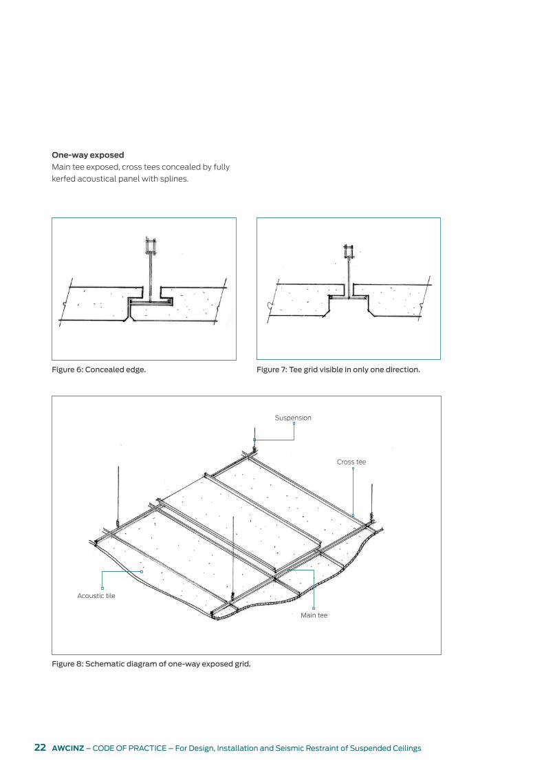
One-way exposed
Main tee exposed, cross tees concealed by fully
kerfed acoustical panel with splines.
Figure 6: Concealed edge. Figure 7: Tee grid visible in only one direction.
Figure 8: Schematic diagram of one-way exposed grid.
Suspension
Cross tee
Acoustic tile
Main tee

23AWCINZ – CODE OF PRACTICE – For Design, Installation and Seismic Restraint of Suspended Ceilings
Fully concealed
For fully concealed grid systems, the main tee,
cross tees and splines are concealed by fully
kerfed acoustical tiles.
Figure 9: Back-to-back L splines. Figure 10: C and Z splines.
Figure 11: Tee grid. Figure 12: Concealed grid.

24 AWCINZ – CODE OF PRACTICE – For Design, Installation and Seismic Restraint of Suspended Ceilings
Plasterboard or other sheet-lined suspension
systems
Steel framing systems expressly designed for
attaching sheet linings such as plasterboard,
fibrous plaster and fibre cement.
Figure 13: Suspended sheeted or flush ceiling grid system.
Figure 14: Direct fix sheeted or flush ceiling system.
Ceiling hanger
Interchange clip between furring channels and primary rail
Height adjustment clip where required
Perimeter trim
Furring channel
Primary rail/strongback
Lining
Perimeter trim
Lining
Furring channel
Direct fix clip between furring channels
Structure

25AWCINZ – CODE OF PRACTICE – For Design, Installation and Seismic Restraint of Suspended Ceilings
Specialty or feature ceilings
These allow the designer to create custom
design far beyond the usual limits of standard
ceilings. Specialty ceilings give the ability for
unique innovative installations.
Figure 15: Finished feature ceilings.

26 AWCINZ – CODE OF PRACTICE – For Design, Installation and Seismic Restraint of Suspended Ceilings
Linear and metal
Figure 16: Suspended linear or strip ceiling system.
Ceiling hanger
Suspended clip for linear strips where required
Height adjustment clip where required
Perimeter trim
Primary rail/strongback
Linear strip

27AWCINZ – CODE OF PRACTICE – For Design, Installation and Seismic Restraint of Suspended Ceilings
Curved ceilings
May be curved in one, two or three dimensions.
Panels may be formed or flat and flexible to
conform to the curve of the ceiling.
Figure 17: Curved ceiling schematic.
Figure 18: Proprietary linear ceiling system.

28 AWCINZ – CODE OF PRACTICE – For Design, Installation and Seismic Restraint of Suspended Ceilings
Floating cloud Ceilings below other ceilings
Figure 19: Floating cloud ceilings.
Figure 20: Feature ceiling below another ceiling.
29AWCINZ – CODE OF PRACTICE – For Design, Installation and Seismic Restraint of Suspended Ceilings
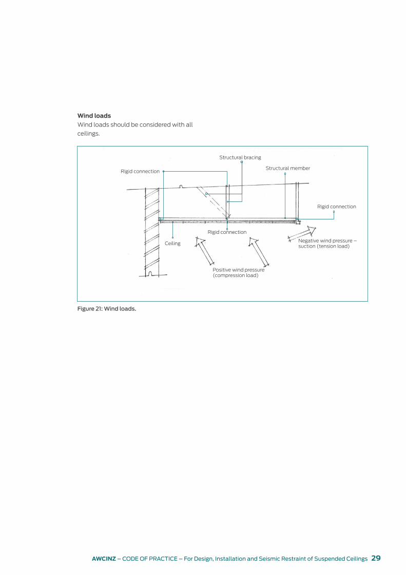
Wind loads
Wind loads should be considered with all
ceilings.
Figure 21: Wind loads.
Ceiling
Rigid connection
Structural bracing
Structural member
Negative wind pressure – suction (tension load)
Rigid connection
Positive wind pressure (compression load)
Rigid connection

30 AWCINZ – CODE OF PRACTICE – For Design, Installation and Seismic Restraint of Suspended Ceilings
BULKHEADSBulkheads are typically used to create boxed-in
areas to conceal structural elements/services or
to separate ceilings of differing heights.
Figure 22: Bulkhead off solid underfloor.
Figure 23: Bulkhead off solid underfloor with two ceilings at different heights.
Stud
Lining
Track
Exposed grid system
Brace
Track top and bottom
Tiled ceiling
Lining
Lining

31AWCINZ – CODE OF PRACTICE – For Design, Installation and Seismic Restraint of Suspended Ceilings
Figure 24: Suspended ceiling and bulkhead, cantilevered top ceiling support.
Figure 25: Suspended ceiling and bulkhead.
Provide suspension close to bulkhead
BraceLining
Wall angle
Allow gap for lining to slot into
Provide 45 degree brace to prevent rocking
Provide suspension close to bulkhead
Lining
Allow gap for lining to slot into
Wall angle
Pop rivet

32 AWCINZ – CODE OF PRACTICE – For Design, Installation and Seismic Restraint of Suspended Ceilings
Figure 26: Suspended ceiling and light trough bulkhead.
Figure 27: Suspended ceiling to blind box detail.
Lining
LightBrace

33AWCINZ – CODE OF PRACTICE – For Design, Installation and Seismic Restraint of Suspended Ceilings
Figure 29: Shadow trims, various sizes.
CEILING COMPONENTS
Wall trims and perimeter channels
Trims and channels are available in varying
profiles to match the grid.
Figure 31: Wall shims, used at edges of ceilings to accommodate sloped ceilings.
Figure 28: L trims, various sizes, equal and unequal leg length.
Figure 30: C channels, various sizes.

34 AWCINZ – CODE OF PRACTICE – For Design, Installation and Seismic Restraint of Suspended Ceilings
Fixing clips
Providing connection options that allow some
expansion movement within a perimeter-
attached suspended ceiling.
Figure 35: Three-way cross joint clip for off-module connection.
Figure 32: Perimeter clips. Figure 33: Main beam joint clip.
Figure 34: Cross tee joint clip.

35AWCINZ – CODE OF PRACTICE – For Design, Installation and Seismic Restraint of Suspended Ceilings
Main tees
Standard length is 3600 mm. Other non-
standard sizes may be project specified and
manufactured to order. Available with a 24 mm
Figure 36: Main tee, 24 mm face. Figure 37: Fire-rated main tee, 24 mm face.
Figure 38: Main tee, 15 mm face.
or 15 mm visible face. Imperial sizes for
refurbishment are also available.

36 AWCINZ – CODE OF PRACTICE – For Design, Installation and Seismic Restraint of Suspended Ceilings
Cross tees
Standard lengths are 1200 mm and 600 mm.
Other non-standard sizes may be project
specified and manufactured to order. Available
Figure 39: Cross tee, 24 mm face. Figure 40: Cross tee, 15 mm face.
with a 24 mm or 15 mm visible face. Imperial
sizes for refurbishment are also available.

37AWCINZ – CODE OF PRACTICE – For Design, Installation and Seismic Restraint of Suspended Ceilings
Testing of product7
The relevant standards to prove compliance
for New Zealand conditions include, but are not
limited to:
y AS 1397-2011 Continuous hot-dip metallic
coated steel sheet and strip – Coatings of
zinc and zinc alloyed with aluminium and
magnesium
y AS/NZS 4600:2005 Cold-formed steel
structures.
A minimum of 10 standard production samples
shall be tested to ensure a fair representation
of what variability products achieve. Minimum
failure values shall apply (not the average).
Variability factors shall be applied (AS/NZS
4600:2005 Table 6.2.2.) subject to the actual
number of samples tested.

38 AWCINZ – CODE OF PRACTICE – For Design, Installation and Seismic Restraint of Suspended Ceilings
Manufacturers’ generic seismic design guides
8
Global suspended ceiling manufacturers provide
generic seismic design guides that calculate the
seismic design detail requirements for many
common non-SED ceiling installation situations.
Being generic, they are conservative, and there
can be limitations on how they are used.
If a manufacturer’s generic seismic design guide
is used, the working sheets must be submitted
with the PS3. Manufacturers’ generic seismic
design guides are the only proof of compliance
when not an SED.

39AWCINZ – CODE OF PRACTICE – For Design, Installation and Seismic Restraint of Suspended Ceilings
Specific engineering design (SED)
9
Projects that are more complex than those
that can be designed from the manufacturers’
generic seismic design guides are classified as
specific engineering design (SED).
Reasons why a project would be classified as
SED include (but are not limited to):
y complexity of the ceiling
y size of the ceiling
y building importance level
y floor to ceiling height
y ceiling to structure (plenum) height
y other building components in the plenum
y design working life (annual probability of
exceedance).
Manufacturers’ design guides for lined
plasterboard ceilings or bulkheads are becoming
more available. Check manufacturers’ or
suppliers’ websites for the most up-to-date
information.
The designer will need to decide if an SED is
required or whether manufacturers’ generic
design guides are appropriate.
A Chartered Professional Engineer (CPEng)
must be engaged to carry out all specific
engineering designs.
40 AWCINZ – CODE OF PRACTICE – For Design, Installation and Seismic Restraint of Suspended Ceilings
Generic details10
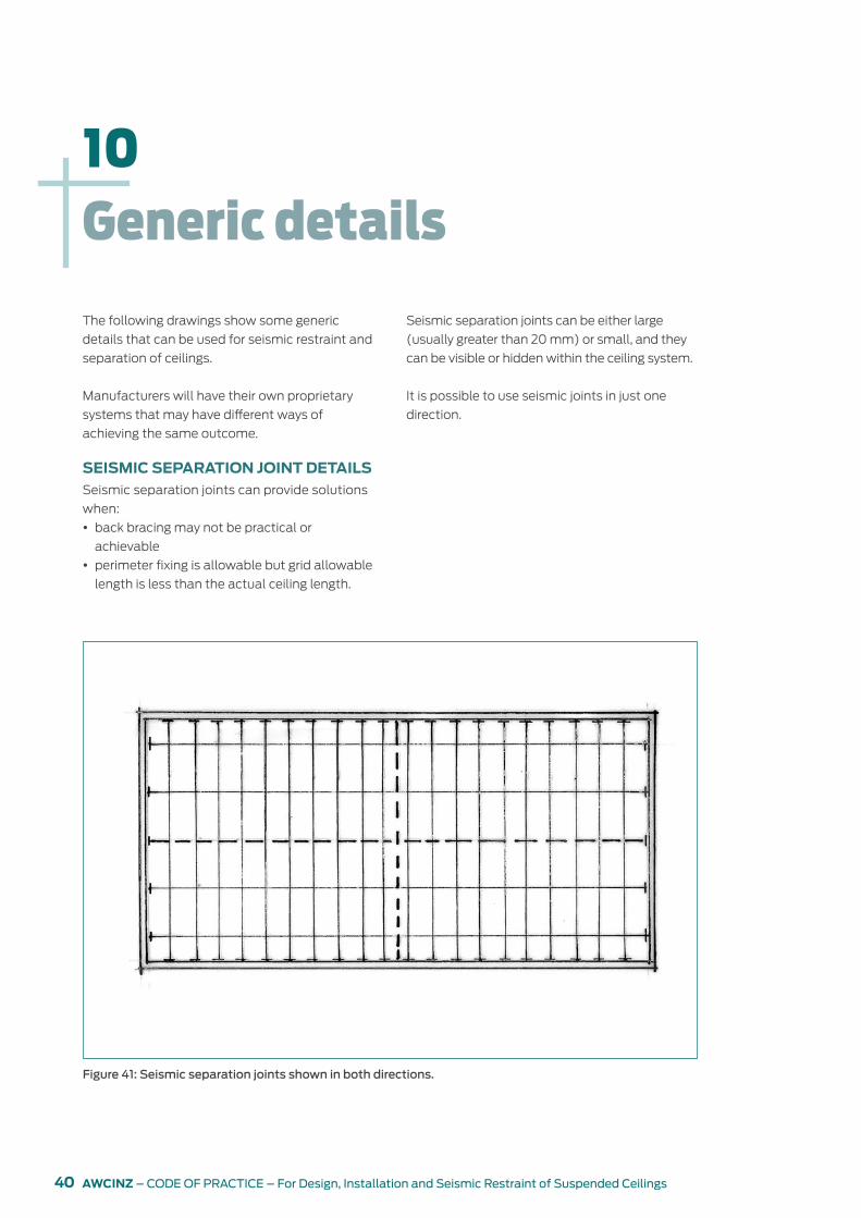
The following drawings show some generic
details that can be used for seismic restraint and
separation of ceilings.
Manufacturers will have their own proprietary
systems that may have different ways of
achieving the same outcome.
SEISMIC SEPARATION JOINT DETAILSSeismic separation joints can provide solutions
when:
y back bracing may not be practical or
achievable
y perimeter fixing is allowable but grid allowable
length is less than the actual ceiling length.
Seismic separation joints can be either large
(usually greater than 20 mm) or small, and they
can be visible or hidden within the ceiling system.
It is possible to use seismic joints in just one
direction.
Figure 41: Seismic separation joints shown in both directions.

41AWCINZ – CODE OF PRACTICE – For Design, Installation and Seismic Restraint of Suspended Ceilings
Figure 45: Seismic joint clip – cross tee.
Figure 42: Small seismic joint, two directions, hidden joint.
Figure 43: Small seismic joint, one direction, hidden joint.
Figure 44: Seismic joint clip – main beam.

42 AWCINZ – CODE OF PRACTICE – For Design, Installation and Seismic Restraint of Suspended Ceilings
Figure 46: Large seismic joint with concave cover strip.
Figure 47: Large seismic joint with cover strip at bottom of T-rail.
Figure 48: Large seismic joint with cover strip above T-rail.
Cover plate fixed to one side only
Gap to be determined by engineer
Closed-cell foam strip (or similar) flexed concave
White or black faced polyester infill

43AWCINZ – CODE OF PRACTICE – For Design, Installation and Seismic Restraint of Suspended Ceilings
LATERAL FORCE BRACING
Lateral force bracing can be provided by
perimeter restraint, K-bracing or use of vertical
struts (compression posts) and supporting
bracing for exposed grid systems.
Lateral force bracing shall be calculated from
the manufacturers’ generic design guides or
subject to SED.
Seismic braces shall be attached to the grid and
to the structure in such a manner that they can
support a design load as calculated.
Support braces are to be within 50 mm of
the connection of the vertical strut to the
suspended ceiling.
Vertical struts must be positively attached to the
suspension systems and the structure above.
The vertical struts may be angles, metal studs or
a proprietary compression post.
Figure 50: Lateral force bracing using splayed wires.
Figure 49: Lateral force bracing using solid struts.
45o or less
Splayed brace wire
45o or less45o or less
45o or less

44 AWCINZ – CODE OF PRACTICE – For Design, Installation and Seismic Restraint of Suspended Ceilings
PERIMETER RESTRAINT
Generally, one end of the ceiling grid shall be
attached to the wall moulding or wall, and the
other end shall have a clearance from the wall
and be free to slide, with the required gap to be
determined by the seismic design.
Figure 51: Proprietary wall clip. Figure 52: Proprietary wall clip in place.
Attachment is typically with aluminium pop
rivets or proprietary engineered components.
45AWCINZ – CODE OF PRACTICE – For Design, Installation and Seismic Restraint of Suspended Ceilings
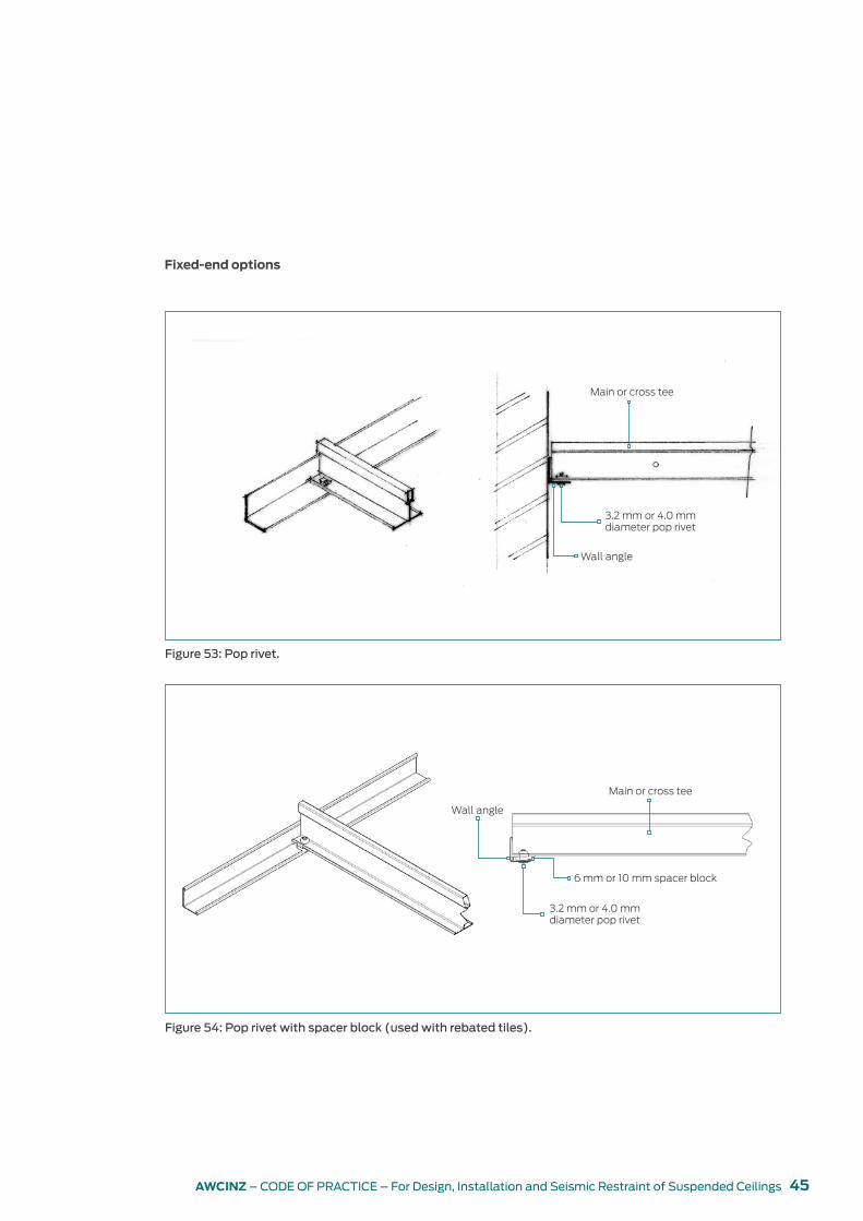
Figure 53: Pop rivet.
Fixed-end options
Figure 54: Pop rivet with spacer block (used with rebated tiles).
3.2 mm or 4.0 mm diameter pop rivet
Wall angle
Main or cross tee
Wall angle
Main or cross tee
6 mm or 10 mm spacer block
3.2 mm or 4.0 mm diameter pop rivet

46 AWCINZ – CODE OF PRACTICE – For Design, Installation and Seismic Restraint of Suspended Ceilings
Figure 55: Seismic clip – main or cross tee.
Figure 56: Seismic clip – cross tee with spacer block.
Spacer block

47AWCINZ – CODE OF PRACTICE – For Design, Installation and Seismic Restraint of Suspended Ceilings
Figure 57: Seismic clip – main or cross tee with spacer block and shadow wall angle.

48 AWCINZ – CODE OF PRACTICE – For Design, Installation and Seismic Restraint of Suspended Ceilings
Figure 58: Seismic clip – wall angle and wall angle with spacer block.
Non-fixed-end options
The grid shall be attached at two adjacent walls
(pop rivets or other approved method).
There must be solid blocking in the wall or a
solid wall capable of taking the lateral force of
the ceiling.
The two other adjacent sides left to move freely
shall be restrained sufficiently to not allow the
grid or tiles to collapse, typically achieved with a
channel wall moulding, proprietary components
or specific design.
Figure 59: Seismic channel.
Minimum distance as per manufacturer’s specs
Maximum distance as per manufacturer’s specs

49AWCINZ – CODE OF PRACTICE – For Design, Installation and Seismic Restraint of Suspended Ceilings
TILE CLIPS
Tile clips can help retain tiles in a ceiling
against vertical movement in a seismic event,
wind pressure and if required under specific
engineering design (SED).
Refer to manufacturers’ recommendations.
HANGERSThe requirements for hangers are as follows:
y Hanger and perimeter wires must be plumb
within 1 in 6 unless counter-sloping wires are
provided.
y Suspension hangers shall be spaced at 1200
mm centres maximum or as specified for the
loading.
y Shot-fired fasteners into concrete are to be
approved for the individual site.
y When using concrete anchors, they
shall be installed in accordance with the
manufacturer’s recommendations, taking due
care to maintain minimum edge distances,
spacing and embedment depth in accordance
with NZS 3101:2006 Concrete structures
standard clauses 17.5.5 and 17.6.
y Cast-in anchors often present alignment
problems for suspended ceilings.
y Fixings into aerated concrete or lightweight
concrete requires special attention and
shall only be made in accordance with the
manufacturer’s recommendations.
y Refer to specific values in AS/NZS 2785:2000
clause 3.2.2 (c) of 50 kg plus factors to
allow for variability in Table 6.2.2 in AS/NZS
4600:2005.
Figure 60: Hanger wire minimum tie-off.
y Wires shall not attach to or bend around
interfering material or equipment. A bridging
system or similar device shall be used where
obstructions preclude direct suspension.
The bridge type and suspensions shall be
engineered for the spans as required. Refer to
AS/NZS 4219:2009 Table 15.
y All wire ties are to be three tight turns around
itself within 75 mm (see Figure 60), 2.5 mm
diameter hanger wire spaced 1200 mm on
centre maximum.
Minimum 76 mm

50 AWCINZ – CODE OF PRACTICE – For Design, Installation and Seismic Restraint of Suspended Ceilings
BRIDGING
Bridging is required when hanger points cannot
be accessed because of obstruction by services.
Best practice is to co-ordinate services to allow
access to hanger points.
The two details shown in Figure 61 are a
guide for ceiling supports around and next
to services. Services are required to comply
with NZS 4219:2009, which specifies seismic
clearances between adjacent building services
components as well as between building
services components and other non-structural
components, for example, including ceilings.
Figure 61: Bridging under ducts or services by other trades.
Min. 50 mm
Light fitting
Ducting Ducting
Ducting
Ducting
1200 mmCeiling hanger
Cable brace
Rigid brace
Light fittingMin. 50 mm
Bridging option

51AWCINZ – CODE OF PRACTICE – For Design, Installation and Seismic Restraint of Suspended Ceilings
Figure 62: Typical trapeze.
TRAPEZE
An opposing angle wire suspension system
can be used where hanger points cannot be
accessed because of obstruction by services.
Figure 63: Trapeze wire detail.
Main vertical suspension greater than allowable
Steel purlins
Roof
No greater than 45o
CeilingTrapeze wires pick up mid-point of span to carry the load
Ceiling will want to be stressed this way
Two trapeze wires required to keep the ceiling balanced – one only will not work

52 AWCINZ – CODE OF PRACTICE – For Design, Installation and Seismic Restraint of Suspended Ceilings
There are many reasons for possible failure of the
suspended ceiling, including but not limited to:
y unsuitable ceiling design
y the use of an unsuitable product/system
y installation not meeting the requirements of
either the manufacturer, supplier or the NZBC
y ceiling wires not installed correctly
y services within the ceiling space or connected
to the ceiling grid not complying with current
codes
y perimeter hangers or bulkheads having
insufficient strength to receive the line loads of
a ceiling
Possible reasons for and consequences of failure
11
Figure 64: Lack of suspension points and service clearance.
Figure 65: Unbraced partitions and service ducts.
y insufficient seismic gaps to allow for
movement of the building structure or other
non-structural elements
y partitions being connected to the ceiling
system but not independently braced
y a lighter gauge of ceiling grid or non-tested
system being installed outside its structural
capability
y interference from other non-structural building
components in the plenum.
Figure 66: Sprinkler system supported from ceiling componentry rather than suspended from the building structure.
53AWCINZ – CODE OF PRACTICE – For Design, Installation and Seismic Restraint of Suspended Ceilings
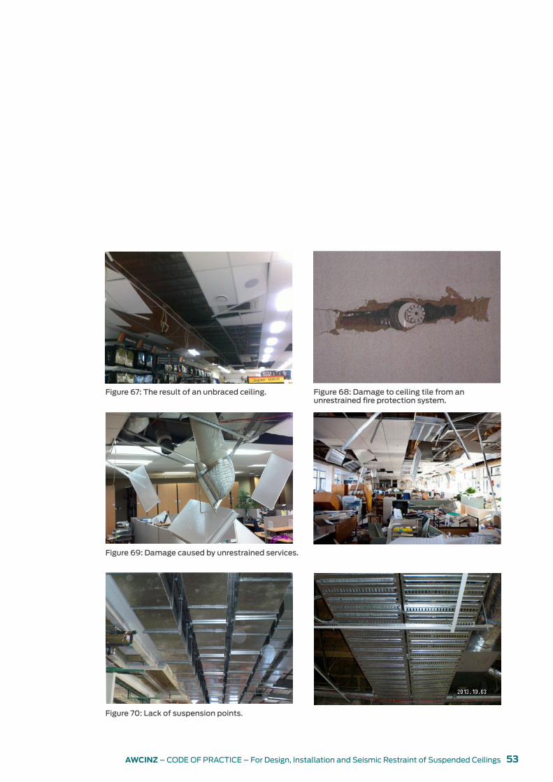
Figure 68: Damage to ceiling tile from an unrestrained fire protection system.
Figure 69: Damage caused by unrestrained services.
Figure 67: The result of an unbraced ceiling.
Figure 70: Lack of suspension points.

54 AWCINZ – CODE OF PRACTICE – For Design, Installation and Seismic Restraint of Suspended Ceilings
Suspended ceiling contractors tendering for
suspended ceilings must consider and make
due allowance for the cost implications of the
seismic restraints and seismic design that will be
required and clearly identify the provisions that
have been made.
OPTIONS FOR TENDERINGThe need for ceilings to be seismically resistant
is not new. However, there is a new awareness
of the need to be able to demonstrate that
installed ceilings have been properly seismically
restrained.
A suspended ceiling contractor shall check at
the time of tendering the actual requirements
for each ceiling, having regard to its designated
AWCI seismic grade and the requirements of
the tender documents. The tender documents
should include structural engineering
information required for tender options 2 and
3, including annual probability of exceedance,
building importance level, building component
category, SLS/ULS, provisions for load transfer
to structure, requirements for producer
statement and any confirmation that services
loads will be restrained in accordance with NZS
4219:2009.
In the interests of ensuring true competition in
the marketplace, each company must determine
its own commercial terms, including but not
limited to the prices charged, the risks accepted
and the wording of its tenders. Therefore, any
AWCINZ recommendations regarding tendering
methodologies are advisory only and are
intended to raise awareness of the issues that
should be considered in determining a tender
price. Suspended ceiling contractors should also
be mindful that qualified (or tagged) tenders
may be treated as non-compliant and may
not be considered. The options developed by
AWCINZ in its tendering protocol are designed to
assist tenderers to:
Tendering 12
y submit offers based on consistent information
y reduce the number of tags
y reduce the number of on-site variations
y reduce the number of on-site work conflicts
with other trades
y give a more accurate costing
y reduce the number of variables in the tender.
There are three main options for responding to
tenders. The response will depend on the level
of information available at the time of tender.
OPTION 1: WHERE TENDER DOCUMENTS INCLUDE FULL DETAILS OF SEISMIC RESTRAINTSThis option is preferred to encourage fully
conforming and untagged tenders and to assure
fully compliant ceiling installations. Prepare the
tender to include the following qualifications.
Model tender qualification where seismic
restraints are fully detailed
We have allowed for the seismic restraints as
detailed on the understanding that they have
been fully designed and detailed in the tender
documents to conform with the requirements of
AS/NZS 2785:2000 and NZS 1170.5:2004. The
suspended ceiling contractor will be responsible
only for the installation of the restraints as
detailed and for the provision of the associated
construction producer statement (PS3) to
confirm that the ceiling has been constructed in
accordance with the design.
Any additional bracing or modification to the
ceiling system to achieve the required level of
seismic bracing or to co-ordinate with structural
elements or building services shall be a variation.
We have not allowed for any engineering
design, design producer statements (PS1, PS2),
installation review by engineer (PS4) or for any
additional work that may be required to co-
ordinate the ceiling supports and restraints with

55AWCINZ – CODE OF PRACTICE – For Design, Installation and Seismic Restraint of Suspended Ceilings
other services and their associated restraint
systems and spatial requirements.
OPTION 2: WHERE SEISMIC RESTRAINT DESIGN IS REQUIRED TO BE CARRIED OUT AT CONSTRUCTION STAGEUnless seismic restraints have been fully
designed and detailed in tender documents, it
is unlikely that the documents supplied to the
suspended ceiling contractor will have enough
information to determine the seismic restraints
requirements and their interface with the
structural elements and building services.
As the nature and cost of seismic details will
not be known until completion of design by the
seismic specialist, this methodology will require
the inclusion of provisional sum allowances in
tenders for seismic restraints.
Ideally, the provisional sum allowances, based
on the nominated seismic grade and any
additional bracing requirements over and above
the minimum required to comply with the
NZBC will be specified in tender documents.
Where this is not done, the suspended ceiling
contractor should nominate a provisional
sum allowance in the tender and include that
allowance in its tender price.
This option encourages fully conforming
tenders generally limited to category P7 (NZS
1170.5:2004 Table 8.1) ceilings to serviceability
limit state (SLS1) (with limited ULS options
also available). Option 2 tenders should identify
the proposed bracing concept, the applicable
manufacturer’s generic design guide and any
underlying design assumptions.6 Any ceilings
outside the scope of manufacturers’ generic
design guides should be nominated in the
tender and identified for specific engineering
design and a provisional sum allowed for
engineer-designed bracing as option 3.
Model tender qualification where seismic
restraints are not detailed in tender
documents
We have allowed for ceilings to be
constructed to the following seismic grades
in accordance with the AWCINZ Code of
Practice for Design, Installation and Seismic
Restraint of Suspended Ceilings:
y Ceiling [identify] – seismic grade AWCI
SG[number]
y Ceiling [identify] – seismic grade AWCI
SG[number]
As the seismic restraints have not been fully
designed, we have allowed a provisional sum
of $[state amount included in tender price].
[OR, where a provisional sum is nominated in
the tender documents]
We have allowed the specified provisional
sum of $[state amount included in tender
price].
The provisional sum shall cover all costs
associated with specialist engineering
design and issue of associated design
producer statements (PS1), any design
review statement (PS2), the supply
and installation of seismic bracing and
engineering monitoring and provision of
engineer producer statements (PS4) that
may be required for the actual seismic
restraints.
OPTION 3: SPECIFIC ENGINEERING DESIGN Specific engineering design is required where
option 1 does not apply and option 2 does not
apply to some or all ceilings.
Unless full engineering data has been provided
within the tender documents, such design must
be carried out post-tender when full structural

56 AWCINZ – CODE OF PRACTICE – For Design, Installation and Seismic Restraint of Suspended Ceilings
and building performance data is available. Where
the scope of seismic bracing cannot be accurately
ascertained at tender, a provisional sum7 should be
nominated for the added cost of bracing.
Model tender qualification where specific
engineering design is required
We have allowed for ceilings to be
constructed to the following seismic grades
in accordance with the specific engineering
design supplied.
The main contractor shall, without charge to
the ceiling contractor:
y provide suitable fixing points and all
secondary steelwork, purlin blockings and so
on for fixing of ceiling hangers and bracing
y provide continuous nogs to allow solid fixings
wherever ceilings abut partitions and bulkheads
y ensure that all in-ceiling services are installed
strictly in accordance with NZS 4219:2009
including that all components and services
over 10 kg are restrained from gravity and
earthquake forces with proper clearances
from ceiling and supports in accordance with
NZS 4219:2009
y co-ordinate the required bracing with
structure and in-ceiling services.
Any requirement for additional steelwork
to modify proposed bracing or support
requirements due to a lack of structural fixings
and support or for co-ordination with in-ceiling
services is a variation.
GENERAL TENDER QUALIFICATIONS y Producer statements, where specified, shall
be provided for the entire design and/or the
completed ceiling installation. Any additional
or interim producer statements for separate
areas or completion stages shall be a variation.
y Drawings shall comprise as a minimum
reflected ceiling plans marked up to show
the position and type of seismic bracing and
seismic control provisions.
y Drawings submitted for approval shall, unless
approved in writing, be deemed approved
within 10 working days of submittal.
TENDER, CONSENT AND SHOP DRAWINGSSeveral types of drawings can be produced
for a project. The contract type will determine
what will be produced and by whom:
y Tender documents can give performance
requirements for the suspended ceiling or can
be more detailed, depending on the nature of
the design methodology. They must contain
at least some minimum physical information
as well as the finished aesthetic. Usually
produced by the lead designer.
y Consent drawings must show how the
proposed system meets the requirements
of the NZBC and the relevant clauses (B1
Structure and B2 Durability). Usually produced
by the lead designer.
y Shop drawings show every nut, bolt or
washer so that all components can be priced
accurately. Produced by the installing company.
Shop drawings define the seismic restraint
types and locations, engineering calculations,
inspections for construction monitoring
and certification. The development of shop
drawings for seismic restraints requires:
y co-ordination of the designer’s reflected
ceiling plans with structural and architectural
features and partitions
y co-ordination of ceilings with building services
installed within the ceiling void attached to or
suspended above or adjacent to the ceiling
and other architectural features
y co-ordination of ceiling and above-ceiling
services restraints and seismic clearances
y providing support and bracing of building
services and other components over 10 kg
supported by the ceiling system.
This may require attendance on co-ordination
meetings and discussions with relevant services
and partitioning trades as early as practicable to
establish methodologies for key co-ordination
issues.
Design details and appropriate producer
statements may be required in the consent
application and project specification.
6 Unless otherwise stated in the ceiling contractor’s tender, underlying assumptions include building importance level of 3 or less (AS/NZS 1170.0:2002 Table 3.2), relevant geographic location (NZS 1170.5:2004 Table 3.3), annual probability of exceedance 1/25 (AS/NZS 1170.0:2002 Table 3.3) and adequate space and fixing provisions for installation of compliant seismic restraints. The main contractor or the client’s structural engineer should verify tenderers’ stated assumptions post-tender when full engineering data is available and any required additional bracing should be a variation.
7 A provisional sum (not being an estimate) for seismic bracing should identify the ceiling areas requiring specific engineering design to cover the cost of specialist engineering design, design producer statements (PS1), supply and installation of seismic bracing and engineer producer statements (PS4) for the actual seismic restraints. Unless otherwise stated, such provisional sum would be additional to the tender price.

57AWCINZ – CODE OF PRACTICE – For Design, Installation and Seismic Restraint of Suspended Ceilings
SITE INSPECTION
Internal ceiling installation work is not to
commence until the building is effectively
watertight and the work of all wet trades has
been completed and dried, unless specifically
designed for this situation.
External ceiling work can commence once the
construction above the ceiling is completed.
MATERIAL STORAGE AND HANDLINGCeiling tile faces are the visible finished face, so
ensure hands are clean and grease-free when
handling the tiles.
When materials are stored on site, they must be laid
flat and protected from water or impact damage.
PRE-INSTALLATION CHECKLISTBefore commencing work, the installer needs
to confirm with the project manager the
installation parameters:
y Where will materials be stored? Is it safe and
secure? Is it clean? Will the materials sustain
any damage?
y Will the installer have clear access to do their
work, or will other trades be working in the
same space at the same time?
y Will the installer be able to complete their
work in one continuous time period with no
interference from other trades, i.e. can they
safely leave work incomplete or must they
secure it at the end of each day?
y Will the installer be able to complete their
work on consecutive days?
y Will scaffolding/elevating work platforms be
available for the installer’s use, or do they need
to provide their own?
y Will lighting and power be supplied?
y Who is responsible for clearing waste materials,
and where are these to be deposited?
y Will the space be fully closed in and protected
from external weather before installation
commences?
Installation 13
y Has the set-out point for all subtrades in the
plenum been determined?
FACILITIES FOR INSTALLATION OF SUSPENDED CEILINGSUnless otherwise agreed, a suspended ceiling
contractor is entitled to assume that a builder/
client will provide the following upon request
and free of charge:
y Suitable fixing points and adequate space for
the gravity hangers and seismic restraints for
the suspended ceiling system.
y All secondary steelwork, framing, purlin
blockings and the like in suitable positions to
attach ceiling hangers and braces.
y Continuous nogs to provide for solid fixing to
partitions and bulkheads where ceilings abut.
y All partitions appropriately braced independent
of the ceiling grid by the partition installer to
avoid lateral force on the ceiling grid.
y All in-ceiling services installed strictly in
accordance with NZS 4219:2009.
y All components and services over 10 kg to
be supported by the ceiling system shall
be restrained by the relevant installer from
gravity and earthquake forces, and producer
statements shall be provided.
y Installers of components and services will certify
the actual weight of any services under 10 kg
that are to be supported by the ceiling grid.
y Building services installed with proper
clearances from ceiling and supports in
accordance with NZS 4219:2009.
y In-ceiling services designed with due
allowance for the gravity supports and seismic
bracing that will be required.
Any requirement to provide additional steelwork
or to modify the planned bracing or support
requirements due to a lack of reasonable
provision for gravity fixings and support for the
ceiling and associated bracing, or to overcome
clashes with in-ceiling services, will be treated as
a variation.

58 AWCINZ – CODE OF PRACTICE – For Design, Installation and Seismic Restraint of Suspended Ceilings
BEST-PRACTICE CO-ORDINATION WITH OTHER CEILING SERVICESThe installer should view all drawings relating
to the plenum before commencing installation
work. They need to be aware of other trade work
to be installed in the void, wall/ceiling junctions,
movement joints, seismic restraints or lack thereof.
A meeting should be held with the project
manager and all other trades to ensure that
access, timing, conflicts and so on of all work
in the plenum is co-ordinated. Any conflicts
that arise must be brought to the attention of
the project manager and resolved before any
further work is installed. It is the responsibility
of the installer to visually inspect all aspects of
the project before commencing. If there are any
issues arising, they should be resolved fully via
the project manager before commencing any
work.
INSTALLATION DETAILS TO SEISMIC DESIGNThe designer or engineer is responsible for
a complying workable design. However, the
installer must not carry out any installation if
it is immediately obvious that there is either
a conflict with another building component
or there is a deficiency in the design. If such a
situation arises, the installer must resolve this
with the engineer and project manager before
proceeding any further.
AESTHETICSThere are many design details that can
influence the finished aesthetic of a ceiling
design, both from a design and a good
workmanship perspective. These include:
y construction tolerances
y consistent shadow gaps
y accurate 90 degree angles
y wall angle alignment
y large wall angles ( >25 mm ) often show waves
y level = 1 in 360 maximum.
Installers must be trained either by the supplier
and/or their installation company on the
appropriate health and safety issues.
SPECIALTY TOOLSInstallers must be trained either by the supplier
and/or their installation company on how to
deal with the proprietary fittings for different
types of systems, but the minimum range of
tools that they must know how to use are:
y laser levelling systems
y aviation snips
y pop rivet gun
y hole punch
y hole saw
y screws
y grid clips.
QUALITY ASSURANCEThe two key principles of quality assurance
(QA) are that products are:
y fit for purpose – the product is suitable for the
intended purpose
y right first time – foreseeable mistakes are to
be eliminated.
Though outside the scope of this Code of
Practice, QA includes management of the
quality of raw materials, assemblies, products
and components, services related to production
as well as management, production and
inspection processes.
Site variations can be minimised by carrying out
some pre-installation processes such as:
y checking that the correct product and the
correct volume has arrived
y co-ordinating installation processes with other
trades to remove any conflicts
y reviewing installation drawings for layout and
fixings of all other building components in the
plenum.
Any quality control programme shall include:
y inspection of material and workmanship
y conformance to plans/construction documents
y special inspections
y a thorough inspection throughout and on
completion of the project.
Hand-over sheets shall be signed by all parties
involved to show that the installation has been

59AWCINZ – CODE OF PRACTICE – For Design, Installation and Seismic Restraint of Suspended Ceilings
completed as designed and specified (see
Appendix E for a sample QA sheet).
INSPECTIONAn inspection of ceiling framing prior to
installation of tiles or panels shall include
checking for compliance with the manufacturer’s
recommendations and in particular:
y spacing of support hangers – typically 1200
mm maximum but reduced around the
perimeter to 400–600 mm typically
y angle of hanger support – no more than 1 in 6
from vertical
y fixing of support hangers – screwed to purlin
webs, never hooked over purlin lips, never pop
riveted, never shot-fired fixings
y perimeter fixing – perimeter brackets fixed
where necessary
y adequate support of ceilings beneath large
service ducts or group of closely spaced
services (bridging members may be needed),
and the ceiling system shall not be suspended
from any building services such as ducts
y support around access hatches –
ensure support members are not cut
unless additional trimmers and hangers
are provided, note manufacturers’
recommendations around additional
trimmers to support openings and ensure the
opening will not adversely affect the ceiling’s
performance in an earthquake
y support of lighting – ensure lighting is fixed
into or supported independently as per the
intended design, and note the manufacturer’s
recommendations around additional
trimmers and/or hangers to support lighting
y downlights or other services shall not rely on
the ceiling panel for support – they shall be
installed in rigid infill, for example, MDF board,
supported on the ceiling grid, or the load shall
be transferred back to the ceiling structural
components
y bulkheads shall be attached to the structural
soffit, independent of the ceiling, unless
specifically designed otherwise
y wind uplift – provide back bracing of ceilings
to all external areas and where necessary to
internal installations.
Seismic-specific detail check to include:
y seismic brackets to two adjacent walls and
sliding joint to the other two walls where
specified – ensure screws are fixed in the
correct locations in the brackets, as in some
systems, the screw location is the principal
difference between a sliding and fixed
connection
y back bracing is located as specified and
constructed to the specific bracing details
y seismic joint clips are installed on main beam
connections where recommended by the
manufacturer or ceiling seismic designer
y seismic joint clips are installed on cross tee
connections where recommended by the
manufacturer or ceiling seismic designer.
REFURBISHMENT WORKFor any refurbishment project, work must not
commence before the primary support structure
has been inspected and verified by a suitably
qualified person as being structurally sound
for a suspended ceiling to be hung from and/
or attached to walls. An inspection should
also include any other non-structural building
components already in the proposed plenum or
any new such components to be installed at the
same time.
When extending, modifying or refurbishing
existing ceilings, if available, the same
components as existing shall be used to ensure
a consistent finish.
Note that subsequent changes in the
compliance requirements of the NZBC may
require more extensive work to be carried out
than a replacement of comparable component
or assembly, for instance, there may have been
an increase in the seismic capability required.

60 AWCINZ – CODE OF PRACTICE – For Design, Installation and Seismic Restraint of Suspended Ceilings
Partitions that are tied to the ceiling shall be
laterally braced to the building structure. The
bracing shall be independent of any ceiling
splay bracing system, and the ceiling must not
be perimeter fixed.
Partitions are not to be braced to the ceiling
unless they have been designed to do so, and
Partitions 14
Figure 71: Proprietary internal wall bracing connection (isolated from ceiling movement).
project-specific seismic gaps must be allowed
for through any penetrations in the ceiling.
Here are some examples of partitions that are
supported independently of ceilings.
Figure 72: Generic internal wall bracing connection – wall terminates at ceiling.
Cut steel studs to length required
Brackets fixed to structure above
Fixed through ceiling to partition
Bracing type and spacing to be confirmed by partition installer or engineer
Bracing
Steel top track
Steel stud

61AWCINZ – CODE OF PRACTICE – For Design, Installation and Seismic Restraint of Suspended Ceilings
Figure 74: Horizontal bracing.
Figure 73: Generic internal wall bracing connection – wall terminates above ceiling.
Bracing
Bracing type and spacing to be confirmed by partition installer or engineer
Steel top track
Ceiling tileSteel stud
Wall angle

62 AWCINZ – CODE OF PRACTICE – For Design, Installation and Seismic Restraint of Suspended Ceilings
The fire design of suspended ceilings is outside
the scope of this Code of Practice. The following
information is intended to highlight some
features of fire-rated ceilings.
Fire-rated ceilings may require specific
engineering design for seismic restraint.
A fire-rated ceiling helps prevent fire and/or
heat from reaching a floor or roof above a room
that is on fire. This allows time for evacuation of
the floors above and protects against property
damage.
A fire-rated ceiling system is part of a total
fire-rated assembly, which includes approved
beams, joists and floor or roof assemblies.
The fire resistance rating of a building assembly
(walls, floor/ceilings and so on) refers to the
period of time the assembly will serve as
a barrier to the spread of a fully developed
blaze. It also refers to how long the assembly
can function structurally after it is exposed
to a fire of standard intensity as defined in
AS 1530.4:2014.
The designation for a system to resist the
passage of fire is represented by three
performance measurements and normally
expressed as 60/60/60, 30/30/30 and so on.
Fire and suspended ceilings
15
The numbers indicate minutes, which, in order of
expression, represent:
y structural adequacy – failure occurs when the
specimen collapses under load
y integrity – failure occurs when the specimen
develops cracks or openings through which
flames or hot gases can pass
y insulation – failure occurs when the average
temperature of the unexposed surface
of the specimen increases by more than
140°C above the initial temperature or the
temperature at any point of the unexposed
surface increases by more than 180°C above
the initial temperature.
PASSIVE FIREPenetrations through fire-rated ceilings need to
be protected to the same rating as the ceiling
and adequately restrained so that, in the event
of seismic movement, the fire rating is not
compromised.
This is dictated by the specification and can be
determined by a fire engineer or manufacturers’
product literature as to the type of treatment
required.
The individual who penetrates the passive fire
protection is responsible for ensuring that the
integrity of the passive fire protection is maintained
and/or reinstated after work is completed.

63AWCINZ – CODE OF PRACTICE – For Design, Installation and Seismic Restraint of Suspended Ceilings
The acoustic design of suspended ceilings is
outside the scope of this Code of Practice. The
following information is intended to highlight
some features of acoustic-rated ceilings.
Acoustic ceiling systems are designed to deal
with sound ‘pollution’ – unwanted sound
either from noise within the room or from noise
travelling into or out of the room.
SOUND ABSORPTION (NRC)When sound is reflected by a surface, it loses
part of its energy. This energy loss is called sound
absorption or the sound absorption capability
of that surface. The single number rating of how
much sound an acoustic product absorbs is
called the noise reduction coefficient (NRC).
Acoustics 16
The NRC is expressed as a number between
0.00 and 1.00. The higher the number, the better
the surface acts as an absorber. As a guideline,
an NRC of 0.7 or greater is recommended for
open-plan offices.
SOUND TRANSMISSION (STC, CAC)When sound travels from its source through the
walls, floors and ceilings of adjoining rooms, this
is called sound transmission. The rating system
that evaluates the effectiveness of assemblies
to isolate airborne sound transmission is called
the sound transmission class (STC). The ceiling
attenuation class (CAC) is a related rating
system specifically for sound transmission
through the ceiling and plenum. A CAC of 40–44
is recommended for closed-plan offices.
Figure 75: Sound reflection.
NRC 0.70+ for best results

64 AWCINZ – CODE OF PRACTICE – For Design, Installation and Seismic Restraint of Suspended Ceilings
All materials absorb, reflect and dampen
sound vibrations to some extent. Truly acoustic
materials absorb sound to a measurable degree,
with a minimum NRC of 0.50.
Figure 76: Sound transmission.
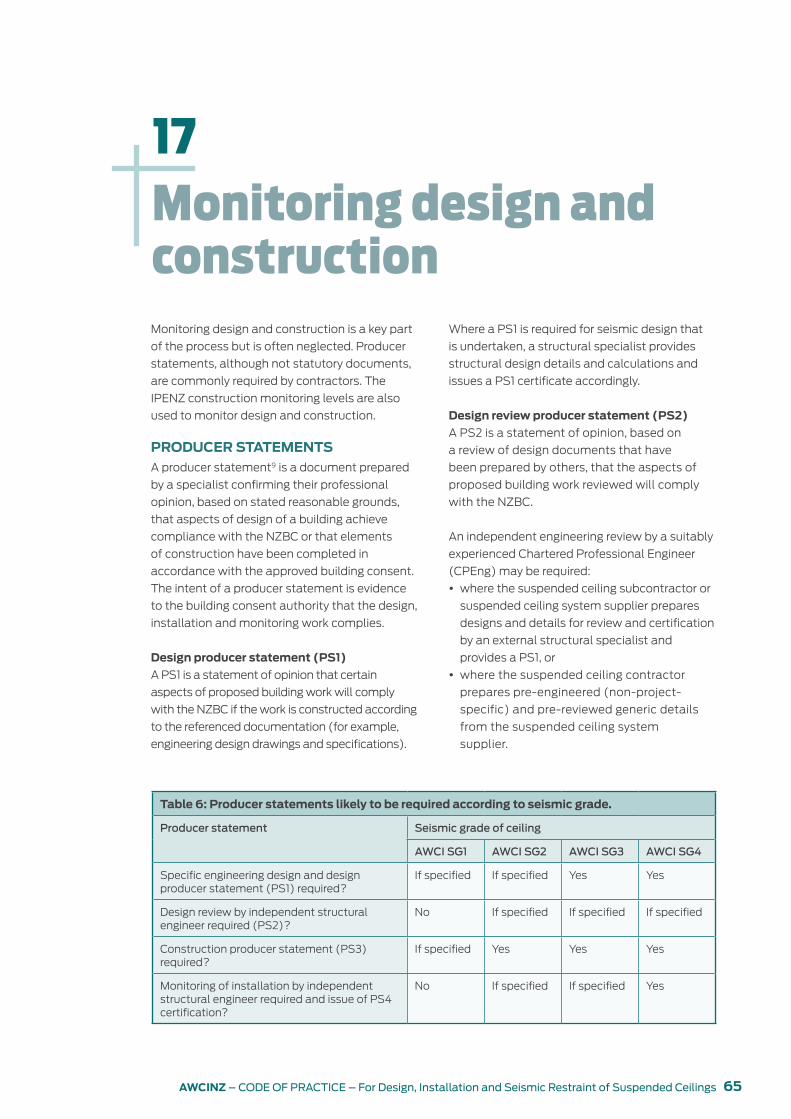
65AWCINZ – CODE OF PRACTICE – For Design, Installation and Seismic Restraint of Suspended Ceilings
Monitoring design and construction is a key part
of the process but is often neglected. Producer
statements, although not statutory documents,
are commonly required by contractors. The
IPENZ construction monitoring levels are also
used to monitor design and construction.
PRODUCER STATEMENTSA producer statement9 is a document prepared
by a specialist confirming their professional
opinion, based on stated reasonable grounds,
that aspects of design of a building achieve
compliance with the NZBC or that elements
of construction have been completed in
accordance with the approved building consent.
The intent of a producer statement is evidence
to the building consent authority that the design,
installation and monitoring work complies.
Design producer statement (PS1)
A PS1 is a statement of opinion that certain
aspects of proposed building work will comply
with the NZBC if the work is constructed according
to the referenced documentation (for example,
engineering design drawings and specifications).
Monitoring design and construction
17
Table 6: Producer statements likely to be required according to seismic grade.
Producer statement Seismic grade of ceiling
AWCI SG1 AWCI SG2 AWCI SG3 AWCI SG4
Specific engineering design and design producer statement (PS1) required?
If specified If specified Yes Yes
Design review by independent structural engineer required (PS2)?
No If specified If specified If specified
Construction producer statement (PS3) required?
If specified Yes Yes Yes
Monitoring of installation by independent structural engineer required and issue of PS4 certification?
No If specified If specified Yes
Where a PS1 is required for seismic design that
is undertaken, a structural specialist provides
structural design details and calculations and
issues a PS1 certificate accordingly.
Design review producer statement (PS2)
A PS2 is a statement of opinion, based on
a review of design documents that have
been prepared by others, that the aspects of
proposed building work reviewed will comply
with the NZBC.
An independent engineering review by a suitably
experienced Chartered Professional Engineer
(CPEng) may be required:
y where the suspended ceiling subcontractor or
suspended ceiling system supplier prepares
designs and details for review and certification
by an external structural specialist and
provides a PS1, or
y where the suspended ceiling contractor
prepares pre-engineered (non-project-
specific) and pre-reviewed generic details
from the suspended ceiling system
supplier.

66 AWCINZ – CODE OF PRACTICE – For Design, Installation and Seismic Restraint of Suspended Ceilings
Construction producer statement (PS3)
A PS3 is certification from the suspended ceiling
contractor that the ceiling has been installed in
accordance with the relevant design, New Zealand
standards and/or building consent as applicable.
The suspended ceiling contractor should take
care to ensure that the wording of the PS3
certification accurately reflects the scope of
work that has been carried out.
Construction review producer statement (PS4)
A PS4 is a statement of opinion, based on
reasonable and stated grounds that may include
the records of construction monitoring and
information supplied by the contractor, that
certain aspects of building work have been
completed according to the building consent
and amendments.
Where required by the seismic grade of
the ceiling or by the tender documents, a
structural specialist should provide the level
of construction monitoring they consider
appropriate and issue a PS4.
CONSTRUCTION MONITORING (CM) LEVELS The construction monitoring (CM) levels10
and guidelines below are based on IPENZ
Engineering Practice Guideline – Construction
Monitoring Services.
Level CM2
y Review at the earliest opportunity a sample of
each important work procedure, material of
construction and component for compliance
with the requirements of the plans and
specifications, and review a representative
sample of each important completed work
prior to enclosure or completion as appropriate.
y Be available to provide the constructor with
technical interpretation of the plans and
specification.
This is considered appropriate for building
importance level 1 or 2 buildings being undertaken
by an experienced and competent suspended
ceiling contactor and where a higher than normal
risk of non-compliance is acceptable.
Level CM3
y Review random samples of important
work procedures for compliance with the
requirements of the plans and specifications
and review important completed work prior to
enclosure or on completion as appropriate
y Be available to provide the constructor
with technical interpretation of plans and
specifications.
This is considered appropriate for building
importance level 3 buildings being undertaken by
an experienced constructor when a normal risk
of non-compliance is acceptable or for building
importance level 1 or 2 buildings where the
suspended ceiling contractor is not experienced
in seismic restraints installations.
Level CM4
y Review regular samples of work procedures,
materials of construction and components for
compliance with the requirements of the plans
and specifications and review the majority of
completed work prior to the enclosure or on
completion as appropriate.
This is considered appropriate for all building
importance level 4 buildings where a lower than
normal risk of non-compliance is required and
building importance level 3 buildings where the
services trade contractor is not experienced in
seismic restraint installations.
8 See IPENZ Practice Note 1 Guidelines on Producer Statements, January 2014 – www.ipenz.org.nz/ipenz/forms/pdfs/PN01-Guidelines-on-Producer-Statements.pdf
9 IPENZ CM1 (monitor outputs from another party’s quality assurance programme) and CM5 (full-time on-site monitoring) have not been included as they are not relevant to the construction monitoring required to be carried out by a structural specialist.

67AWCINZ – CODE OF PRACTICE – For Design, Installation and Seismic Restraint of Suspended Ceilings
As with any construction project, there are
many parties involved. All have different roles
and responsibilities, and in many steps of the
process, the roles and responsibilities of several
parties will overlap.
In general, the greater the collaboration and
the earlier communication between all parties
commences, the greater the chances of a
successful project with fewer contract variations,
omissions or parties ending up out of pocket.
DESIGNERThe seismic design of suspended ceilings must
be undertaken by a suitably qualified person.
The designer’s responsibilities are to:
y identify the AWCI seismic grade/requirements
of the ceiling
y design the ceiling
y design appropriate seismic restraints
y issue a PS1 to certify the design
y commission a PS2 if required
y issue a PS4 if contracted to do so.
The lead designer may be an architect, interior
designer or engineer. The lead designer
oversees the entire documentation process
as a whole and must be aware of all the
components in the plenum and how they
interact and ensure that all parties are aware of
all work by others.
Each component in the plenum may also
have its own specialist designer. Ideally, the
lead designer will co-ordinate all other non-
structural building components in the plenum
so that there are no conflicts. They may need to
modify the design to co-ordinate and overcome
clashes with other components and the related
fixings and bracing designed by their structural
specialists.
Summary of roles and responsibilities
18
CEILING TENDERER The ceiling tenderer is the contractor who
supplies and installs the suspended ceiling.
The tenderer’s responsibilities are to:
y ensure all ceiling details ‘work’
y verify the AWCI seismic grade/requirements
of the ceiling (as identified by the designer or
based on the information provided)
y identify a provisional sum allowance for
seismic restraints (as applicable)
y review co-ordination with other trades.
INSTALLERThe installation of suspended ceilings shall be
undertaken by a suitably qualified person with
experience in ceiling installation. A suitably
qualified person will hold a National Certificate
in Specialist Interiors (Installation) and/or be
a certified tradesperson or certified business
member of AWCINZ.
The installer’s responsibilities are to:
y prepare shop drawings (where applicable)
y submit shop drawings (where applicable)
y obtain design approvals (if required)
y install the ceiling in accordance with the
approved shop drawings or seismic design
details.
y inspect seismic restraints for conformance
with approved design
y issue a PS3 to certify that the installation has
been completed in accordance with the design.
Before commencing any work, the installer shall
visually inspect the site and raise any issues
arising with the project manager. The installer
shall also hold a meeting with the project
manager and all other trades with components
in the plenum and supported by the ceiling to
co-ordinate installation scheduling, location of
their components and all fixing points.

68 AWCINZ – CODE OF PRACTICE – For Design, Installation and Seismic Restraint of Suspended Ceilings
BUILDING CONSENT AUTHORITY
Registered building consent authorities perform
building consenting functions under the Building
Act 2004.
The BCA’s responsibilities are to:
y review consent documents for NZBC
compliance, including the requirement for
and design of seismic restraints
y review installation for conformance with
consented drawings.

69AWCINZ – CODE OF PRACTICE – For Design, Installation and Seismic Restraint of Suspended Ceilings
Appendices
A. DEFINITIONS, ABBREVIATIONS AND NOTATIONS
Acceptable Solution
A prescriptive design solution comprising
step-by-step instructions that, if followed, is
deemed to comply with the NZBC. Acceptable
Solutions and Verification Methods are
published by the Ministry of Business,
Innovation and Employment and often cite
other documents such as New Zealand
standards. Designers and builders are not
obliged to use Acceptable Solutions and may
put forward their own Alternative Solution
proposal.
Alternative Solution
A design solution that differs totally or partially
from Acceptable Solutions or Verification
Methods yet complies with the performance
requirements of the NZBC. These are stand-
alone solutions put forward and substantiated
by the building consent applicant and
considered and approved on their individual
merits by a building consent authority.
annual exceedance probability
The chance or probability of a natural hazard
event (usually a rainfall or flooding event)
occurring. Typically defines an earthquake that is
likely to occur during the lifetime of the structure.
AWCI seismic grade
This seismic grade allows designers to identify
the extent to which a suspended ceiling must
be able to resist seismic forces and/or to remain
intact in the event of an earthquake.
brace (see also K-brace, knee brace)
Component used to restrain the ceiling. Usually
attached to the structure above.
bridge
A horizontal bar supported by hangers/wires to
span under ducting or services.
building importance level
Refer Table 5.
ceiling attenuation class (CAC) (see also STC)
Similar to STC, this rating system is specifically
for sound transmission through a ceiling and
plenum.
Chartered Professional Engineer (CPEng)
A statutory title under the Chartered
Professional Engineers of New Zealand
Act 2002, which established a register of
professional engineers whose competence is
up to date.
concealed
Term usually associated with suspension
systems where the ceiling tile fully covers the
suspension framing. Sometimes also used to
describe a plasterboard lined ceiling.
contract variation, site variation
An amendment to a contract that changes the
original terms or conditions of the contract.
cross tees, cross runners, cross T-bars
A cross member that interlocks with a main
beam.
designer
The person who designs the suspended ceiling.
diffuser
A circular or rectangular metal grille used for
the passage of air from a ducted system.
earthquake action, return period
An estimate of the likelihood of an event, such
as an earthquake. Also known as a recurrence
interval.
engineer
Person qualified as an engineer. May not be
chartered.

70 AWCINZ – CODE OF PRACTICE – For Design, Installation and Seismic Restraint of Suspended Ceilings
essential service buildings
Any building designed to be used by public
agencies such as a fire station, Police station,
emergency operations centre or emergency
communications centre.
face load
A force applied at right angles to a building plane.
grid
The main beams and cross tees of the
suspension system.
hanger wire, suspension wire
2.5 mm annealed wire used as the primary
support for the grid system.
hanger
A type of suspension for the ceiling. It may be
wire, rod or a rigid style of brace to resist vertical
movement.
K-brace (see also brace)
A type of brace for the ceiling. It may be wire or a
rigid style of brace to resist horizontal movement
in one direction.
Knee brace (see also brace)
A type of brace, typically used above a partition.
It is normally a rigid style of brace to resist
horizontal movement in one direction.
lateral force bracing
The bracing method used to prevent or to
restrict lateral movement during a seismic event.
linear ceiling
Long lengths of a material, usually light metal,
that form the ceiling.
main beam, main runner, carrying tee,
carrying runner, mains
The primary suspension member supported by
hanger wires.
main contractor
Head builder, usually appoints subcontractors
for specialist building work.
movement joint
Area of connections designed to allow for
movement.
noise reduction coefficient (NRC)
The amount of sound an acoustic product
absorbs.
one-way grid
Tile edge design conceals the grid in one
direction.
perimeter clips
Proprietary angle bracket attached directly to
the wall trim, which allows for movement in the
event of seismic activity and interlocks properly
with the ends of a grid system.
perimeter wires
Hanger wires placed within 200 mm of the
surrounding walls.
plenum
The space between the underside of the structure
above and the suspended ceiling system.
project manager
A person who will be on site and have an
overview of the whole project.
provisional sum
An allowance that is inserted into tender
documents.
return period
See annual probability of exceedance.
reverberation
When a sound wave continues to reflect around
a room after the sound at source has died out.

71AWCINZ – CODE OF PRACTICE – For Design, Installation and Seismic Restraint of Suspended Ceilings
seismic clip
Proprietary clip designed to either restrain or
allow for movement.
seismic joint
Area specified to allow for anticipated movement.
seismic restraint
Components used to resist seismic movement.
seismic strut
Vertical rigid component to resist upward
movement, usually supported by diagonal
braces.
serviceability limit state (SLS) (see also ULS)
The point where a structure can no longer be
used for its intended purpose but would still
be structurally sound.
set-out point
The specified starting point used to lay out the
ceiling.
sheeted ceiling
Where a suspended ceiling is sheet lined and
finished so that there are no air gaps to the
plenum.
slack wire
A safety wire that is not tight or taut.
soil type
Ranges from hard rock to soft soil. The ground
motion of an earthquake is affected by the soil
profile through which the vibrations travel.
sound absorption
The energy lost by a sound when it strikes and
is partially reflected off a surface.
sound transmission class (STC)
A rating system that evaluates the effectiveness
of assemblies to isolate airborne sound.
specific engineering design (SED)
Seismic restraint design specific to a project,
typically outside the scope of manufacturers’
generic seismic design guides.
splay wires
Wires installed at an angle rather than
perpendicular to the grid.
spreader bar, spacer bar, stabiliser bar
A bar with notches to prevent the suspension
system from separating.
strut
A rigid style of brace to resist horizontal and
vertical movement.
suitably qualified person
Person qualified to carry out work.
suspension wire
A wire rod, typically 2.5 mm diameter.
T-rail
An exposed grid.
tag(s), tagged
Design and specification changes that often
have a cost implication.
tenderer
A person or company that puts forward an
estimate of cost.
tight turns
Installation requirement for suspension wire.
trapeze
An opposing angled wire suspension system.
two-way grid
Grid can be seen in both directions.
ultimate limit state (ULS) (see also SLS)

72 AWCINZ – CODE OF PRACTICE – For Design, Installation and Seismic Restraint of Suspended Ceilings
Reached when the applied stresses exceed the
strength of the structure or structural elements.
Verification Method
A prescriptive design solution comprising a
calculation or test procedure, which provides
an approved way of complying with the NZBC.
Verification Methods (along with Acceptable
Solutions) are published by the Ministry of
Business, Innovation and Employment and often
quote other documents such as New Zealand
standards. Designers are not obliged to use the
Verification Methods and may put forward their
own Alternative Solution proposal.
vertical struts, compression posts, seismic
posts, seismic struts
The rigid vertical member used in the bracing of
the suspension system. Common materials are
angles, metal studs or proprietary products.
wall trim, wall moulding
A light-gauge metal wall trim or channel fastened
to the perimeter wall or partition to support the
perimeter ends of an acoustical ceiling grid.
wet trades
Trades involved with installing products that give
off moisture, for example, plastering.

73AWCINZ – CODE OF PRACTICE – For Design, Installation and Seismic Restraint of Suspended Ceilings
B. RELEVANT STANDARDS AND ASSOCIATED DOCUMENTS
Standards
AS/NZS 1170.1:2002 Structural design actions –
Part 1: Permanent, imposed and other actions
NZS 1170.5:2004 Structural design actions – Part
5: Earthquake actions – New Zealand
Provides procedures for the determination
of earthquake actions on structures in
New Zealand. It gives the requirements
for verification procedures, site hazard
determination, the evaluation of structural
characteristics, structural analysis for
earthquake action effects, the determination
and limits for deformations and the seismic
loads on parts of structures. It is to be applied
in conjunction with AS/NZS 1170 parts 0,
1, 2 and 3 and relevant material standards.
Appendices cover aspects of ultimate
limit state design and the requirements for
material-specific structural design standards
that are able to be used in conjunction with
NZS 1170.5:2004.
NZS 1170.5 Supplement 1: 2004 Structural design
actions – Part 5: Earthquake actions – New
Zealand commentary
Provides background to the various provisions
in NZS 1170.5:2004, suggests approaches that
may satisfy the intent of the standard and, if
appropriate, describes differences between
this and previous editions of the standard.
References are provided for further reading,
and these are given at the end of each section
of the commentary.
AS/NZS 1530.3:1999 Methods for fire tests on
building materials, components and structures
– Simultaneous determination of ignitability,
flame propagation, heat release and smoke
release
AS/NZS 2785:2000 Suspended ceilings – Design
and installation
Sets out minimum requirements for the design,
construction, installation, maintenance and
testing of internal and external non-trafficable
suspended ceiling systems of dry construction
with suspension systems attached to a
supporting structure, for use in commercial,
industrial and residential applications.
AS 2946-1991 Suspended ceilings, recessed
luminaires and air diffusers – Interface
requirements for physical compatibility
NZS 3404:2009 Steel structures standard
NZS 4219:2009 Seismic performance of
engineering systems in buildings
NZS 4541:2013 Automatic fire sprinkler systems
AS/NZS 4600:2005 Cold-formed steel structures
Sets out minimum requirements for the design
of structural members cold formed to shape
from carbon or low-alloy steel sheet, strip, plate
or bar not more than 25 mm in thickness and
used for load-carrying purposes in buildings.
AS 1397-2011 Continuous hot-dip metallic coated
steel sheet and strip – Coatings of zinc and zinc
alloyed with aluminium and magnesium
ISO 6308:1980 Gypsum plasterboard –
Specification
ASTM C423-09 Test method for sound
absorption and sound absorption coefficients by
the reverberation room method
ASTM E1414-11 Standard test method for airborne
sound attenuation between rooms sharing a
common ceiling plenum (two-room method)

74 AWCINZ – CODE OF PRACTICE – For Design, Installation and Seismic Restraint of Suspended Ceilings
AS ISO 354-2006 Acoustics - Measurement of
sound absorption in a reverberation room
Other documents
Acceptable Solutions and Verification Methods
for NZBC clause B1 Structure (www.building.
govt.nz/UserFiles/File/Publications/Building/
Compliance-documents/B1-structure-1st-
edition-amendment-12.pdf)
NZBC clause B2 Durability (www.building.
govt.nz/UserFiles/File/Publications/Building/
Compliance-documents/B2-durability-2nd-
edition-amendment-8.pdf)
Codewords Issue 54 – December 2012 – Seismic
resistance for engineering systems and non-
structural elements (www.building.govt.nz/
codewords-issue-054#seismic)
IPENZ Practice Note 1 Guidelines on Producer
Statements, January 2014 (www.ipenz.org.
nz/ipenz/forms/pdfs/PN01-Guidelines-on-
Producer-Statements.pdf)
Generic Seismic Design Guidelines – Suspended
Ceilings, 2014, USG Boral (www.seismicceilings.
co.nz/pdfs/USG%20Seismic%20
Guidelines%203-14.pdf)
C. TENDERING OPTIONS GUIDELINES
AWCINZ has developed a guideline and protocol
to assist in the tendering process. It lists different
design methodologies that will give different
outcomes. It will assist tenderers to:
y submit offers based on consistent information
y reduce the number of tags
y reduce the number of on-site variations
y reduce the number of on-site work conflicts
with other trades
y give a more accurate costing
y reduce the number of variables in the tender.
It is reproduced on the following page or
download at www.awci.org.nz/suspended-
ceilings/.

75AWCINZ – CODE OF PRACTICE – For Design, Installation and Seismic Restraint of Suspended Ceilings
AWCI TENDERING PROTOCOL FOR GRID SUSPENDED CEILING INSTALLATIONS
1. All installed suspended ceilings must comply with AS/NZS 2785:2000 and the seismic restraint
requirements of AS/NZS 1170.5:2004.
2. AWCINZ members are encouraged to submit tenders for grid suspended ceilings based on this AWCI
Tendering Protocol to assure compliance.
3. Options for the design of seismic restraints for Grid Suspended Ceilings include:
Option 1: Full design of ceiling seismic restraints system by structural engineer tender documents
Full seismic restraints design incorporated in building consent documentation and tender documents.
This option is preferred to encourage fully conforming and untagged tenders, and to assure fully
compliant ceiling installations.
Option 2: Generic Design Guides
New Zealand manufacturer/supplier Generic Design Guidesi provide seismic bracing installation
details for basic ceilings within product limitations and structural performance assumptions, for
subcontractor design and pricing.
This option encourages fully conforming tenders generally limited to Category P.7 (AS/NZS
1170.5:2005 Table 8.1) ceilings to Serviceability Limit State (SLS1) (with limited ULS options also
available). Option 2 tenders should identify the proposed bracing concept, the applicable Generic
Design Guide, and any underlying design assumptions*1.
Any ceilings outside the scope of Generic Design Guides (generally being greater than 30/40 metres
above ground level, or where individual components weigh more than 10 kg and are able to fall more
than 3 metres onto a publicly accessible area) should be nominated in the tender and identified for
specific engineering design, and a Provisional Sum allowed for engineer-designed bracing as Option 3.
*1 Unless otherwise stated in the ceiling contractor’s tender underlying assumptions include
building importance level of 3 or less (AS/NZS 1170.0:2002 Table 3.2), relevant geographic
location (AS/NZS 1170.5:2004 Table 3.3), annual probability of exceedance 1/25 (AS/NZS
1170.0:2002 Table 3.3), and adequate space and fixing provisions for installation of compliant
seismic restraints. The main contractor or the client’s structural engineer should verify tenderers’
stated assumptions post-tender when full engineering data is available, and any required
additional bracing should be a variation.
Option 3: Specific engineering design
Specific engineering design (required where Option 1 does not apply, and Option 2 does not apply
to some or all ceilings).
Unless full engineering data has been provided within the tender documents such design must be
carried out post-tender when full structural and building performance data is available. Where the
scope of seismic bracing cannot be accurately ascertained at tender a Provisional Sum*2 should be
nominated for the added cost of bracing.

76 AWCINZ – CODE OF PRACTICE – For Design, Installation and Seismic Restraint of Suspended Ceilings
*2 A Provisional Sum (not being an estimate) for seismic bracing should identify the ceiling areas
requiring specific engineering design, to cover the cost of specialist engineering design, design
producer statements (PS1), supply and installation of seismic bracing, and engineer producer
statements (PS4) for the actual seismic restraints. Unless otherwise stated such Provisional
Sum would be additional to the tender price.
General
y Minimum structural engineering information requirements for Options 2 and 3 include return period,
building importance level, building classification, SLS/ULS, provisions for load transfer to structure,
requirements for producer statement, any confirmation that services loads will be restrained in
accordance with AS/NZS 4219.
y Producer statements, where specified, shall be provided for the entire design and/or the completed
ceiling installation. Any additional or interim producer statements for separate areas or completion
stages shall be a variation.
y Shop drawings shall comprise as a minimum reflected ceiling plans marked up to show the position
and type of seismic bracing and seismic control provisions.
y Shop drawings submitted for approval shall unless approved in writing be deemed approved within
10 working days of submittal.
Coordination of structure and services with ceiling fixings and bracing
The main contractor shall, without charge to the ceiling contractor:
y Provide suitable fixing points and all secondary steelwork, purlin blockings, etc. for fixing of ceiling
hangers and bracing.
y Provide continuous nogs to allow solid fixings wherever ceilings abut partitions and bulkheads.
y Ensure that all in-ceiling services are installed strictly in accordance with AS/NZS 4219 including all
components and services over 10kg are restrained from gravity and earthquake forces with proper
clearances from ceiling and supports in accordance with AS/NZS 4219.
y Co-ordinate the required bracing with structure and in-ceiling services.
Any requirement for additional steelwork, to modify proposed bracing or support requirements due to a
lack of structural fixings and support or for coordination with in-ceiling services would be a variation.
Armstrong: Armstrong Seismic Design Guide – New Zealand Version; Seismic Installations and Armstrong Ceiling Systems
i USG: Generic Seismic Installation for USG DONN® Exposed Grid Suspended Ceilings; Seismic design Guidelines – Suspended ceilings

77AWCINZ – CODE OF PRACTICE – For Design, Installation and Seismic Restraint of Suspended Ceilings
D. INSTALLER’S PRODUCER STATEMENT (PS3) TEMPLATE
The PS3 below is an example of what some
building consenting authorities may require from
the installer.
You should attach the seismic design summary
sheet(s) if you are using a manufacturer’s
generic design guide.

78 AWCINZ – CODE OF PRACTICE – For Design, Installation and Seismic Restraint of Suspended Ceilings
E. SAMPLE QA SHEET
Below is a sample of a QA sheet that should be
completed at the completion of every notifiable
stage of the installation contract and for every
different area of project work.

79AWCINZ – CODE OF PRACTICE – For Design, Installation and Seismic Restraint of Suspended Ceilings
F. DESIGN INFORMATION LIST
Considerations when designing and installing
suspended ceilings include:
y seismic design criteria and seismic design
intent
y risk factors
y accelerations and movements of the primary
building structure during an earthquake
y minimum clearances between hangers/
plenum braces for ceilings and services
y building location
y estimated maximum number of occupants
y ceiling type and manufacturer
y weight of ceiling
y plenum depth
y weight of services
y AWCI seismic grade
y NZS 1170.5:2004 section 8 parts category
y building importance level
y annual probability of exceedance (return period)
y design working life
y ductility of parts and systems
y site hazard factor (Z)
y site subsoil class
y full set of drawings including reflected ceiling
plan and services locations
y wind loads
y inter-storey drift of the structure
y ceiling height from ground and floor
y total height of building
y location of any seismic ceiling gaps
y where recessed luminaires are to be used, they
shall be shown on the reflected ceiling plans
y adequate support of ceilings beneath large
service ducts
y access hatches
y bulkheads
y skylights
y internal partitions.

80 AWCINZ – CODE OF PRACTICE – For Design, Installation and Seismic Restraint of Suspended Ceilings

