for heavy 14/2 summary of r a youshaw ...ad-a99 119 ship structure committee washington dc f/6 14/2...
TRANSCRIPT

"AD-A99 119 SHIP STRUCTURE COMMITTEE WASHINGTON DC F/6 14/2SUMMARY OF NONDESTRUCTIVE INSPECTION STANDARDS FOR HEAVY SECTIO--ETC(U)DEC A0 R A YOUSHAW
UNCLASSIFIED SSC-300 NL
oiIEEEEE

get=1
Amk

Membe Agenies:Address Correspondence to:
United States Coast GuardAbvel See Systems Command Secretary, Ship Structure Committee
Military $Wift Command U.S. Coast Guard Headquarters,(G-M/TP 13)
Maritime Administration Jm. Washington, D.C. 20593
United States Geological Survey i tut*American Bureau of Shipping C
An Interagency Advisory CommitteeDedicated to Improving the Structure of Ships
SR-1255March 1981
As vessels have expanded in size and deadweightduring the last fifteen years, there has been a similarincrease in the size of forgings, castings and heavyweldments used in vessels. Some examples of such componentsare stem and stern frames, rudder horns, stern tubes,tail shafts, propellers, and some engine parts. The ShipStructure Committee became aware of the need to developquantitative guidelines for the nondestructive inspectionof these components.
A project was initiated to survey the literatureand write an interpretative report of the state of the artin this field. While various methods and practices werereviewed and discussed, the user must still specify theacceptance limits to meet the intended service.
The results of the project are contained in this
report.
Rear Admiral, U.S. Coast GuardChairman, Ship Structure Committee
F-- . ,
II

Technical Report Documentation Page
1. Report No. 2 Gose'nment Accession N-. 3. -4e pR.ent's Catalog No.
- SC-34*6J I__; / J t1V,, ho, -AI -2 - - .
Title and Sub title -. ort Dal*
SIJNMARY OF .UPNDESTRUCTIVE SPECTION ANDARDS 80 ZHFOR EAVY ETION CASTINGSFORGINGS, AND WELDMENTS* cr U ,itoCo
_._,,, ___,_-__"__,,,_-_"-__.. ... 88.P.,r T No.Au rhyds -
,OBERT A YOUSHAW9. arlor 9 Otgonzation me o-noan dcldress 10. Wok Un.t No. (TRAIS)
Naval Surface Weapons Center - White Oak ,_---- - I
Silver Spring, MD 20910 .. 7 O..-6-7137513. Type of Report and Pe.oji C.. eMe -
12. Sponsoring Agency Name and Address " FINAL ¢('U.S. Coast Guard r ,Office of Merchant Marine Safety . S A
Washington, D.C. 20593 g
15. Supplementary Notes
Ship Structure Committee Project SR-1255
16. Abstract
Aode bodies, notably AS I1, have produced procedural guides, standardmethods, and recommended practices which can be used to assure properinspection for the various methods of nondestructive testing. Theseguides and practices in private industry have been reviewed for theirapplicability to quality control of heavy steel castings, forgings,3nd weldments. Acceptance criteria are not set forth, andrecommendations are not suggested. They do, however, define levelsof quality and describe the parameters generally agreed to be ofsignificance which should be a part of the contractural agreement.The user must quantify these parameters according to service require-ments and other considerations.._..-..
17. Key WorNdestrcietsig t ;tement .•i
7 sNondestructive testing ' available to the U.S. Publicforgings through the National Technical Informatiolcastings Service, Springfield, VA 22161.radiographi inspectionultra~i in1,1ctIon .nkgneiUc part c et lnspec ion
19. Security Closel. (of this report) 20. Security Classil. (of rh.s page) 21. No. of Pages 22. Price
UNCLASSIFIED UNCLASSIFIED 32
Form DOT F 1700.7 (8-72) Reproduction of completed page autiiorisedJ
mambo&

! 5 .l - - :- - i t
hi-"-ii
'-< * Ii
WA A
S* 'a'.;i~ ,- 3 i ! !i lI UI.I i -'
a. =< U* " oo.- " 0' " " " ' -°' S. " .. -'.
S ",6 .l I I I ! ! 1 I I I I I I I I I I ! i , ' 1 I 1 i : 0 0
1- -
Sc E I 6 1 i 1 1
.+.,-* i ii
ImI
6
04
ItA
ii
- ~ -U

CONTENTS
Page
INTRODUCTION 1
OBJECTIVE AND SCOPE 1
BACKGROUND 1
NONDESTRUCTIVE INSPECTION - GENERAL 2
NONDESTRUCTIVE INSPECTION OF STEEL CASTINGS 2
Radicgraphy 2
Ultrasonic 8
Magnetic Particle Inspection 10
Liquid Penetrant Inspection Method 11
Visual Inspection 12
NONDESTRUCTIVE INSPECTION OF STEEL FORGINGS 15
Radiographic Inspection 15
Ultrasonic Inspection 15
Magnetic Particle Inspection 17
Liquid Penetrant Inspection 18
Visual Inspection 18
NONDESTRUCTIVE INSPECTION OF THICK WELDS 18
Radiography 18
Ultrasonic Inspection 20
Magnetic Particle Inspection 21
Visual Inspection 22
SUMMARY AND CONCLUSIONS 26
TABLES
Table Page
1 Types of Weld Discontinuities and Levels of 19Severity Presented in ASTM E-390
2 Tensile Properties Vs. Severity of Radiographic 24IndiCations
3 Comparison of Endurance Ratios in Bending and 25Torsion
-ii-
06w
ILLUSTRATIONS
Figure Page
1 Illustration of Gas Porosity, Category A, Severity 4Level 5 - from ASTM E-196, Reference Radiographsfor Steel Castings.
2 Illustration of Sand and Slag Inclusions, Category 4B, Severity Level 5 - from ASTM E-186, ReferenceRadiographs for Steel Castings.
3 Illustration of Shrinkage, Type 1, Category C, 5Severity Level 5 - from ASTM E-186, ReferenceRadiographs for Steel Castings.
4 Illustration of Shrinkage, Type 2, Category C,Severity Level 5 - from ASTM E-186, ReferenceRadiographs for Steel Castings.
5 Illustration of Shrinkage, Type 3, Category C, 6Severity Level 5 - from ASTM E-186, ReferenceRadiographs for Steel Castings.
6 Illustration of Linear Discontinuity, Category D, 6Severity Level 5 - from ASTM E-186, ReferenceRadiographs for Steel Castings.
7 Illustration of Inserts, Type 1, Category E, 7Severity Level 5 - from ASTM E-186, ReferenceRadiographs for Steel Castings.
8 Illustration of Inserts, Type 2, Category E, 7Severity Level 5 - from ASTM E-186, ReferenceRadiographs for Steel Castings.
9 Wrinkles, Laps, Folds, and Coldshuts from Quality 13Standard for Steel Castings S-P-55 (VisualMethod).
10 Average Strength of Cast Tensile Bars for Various 22Degrees of Shrinkage Severity.
11 Effect of Shrinkage on Plate Bending Fatigue of 22Cast Sections of Normalized and Tempered 8630Ni-Cr-Mo Steel.
12 Bending Fatigure for Normalized and Tempered 8630 23Cast Steel Containing Surface Discontinuities.
13 Torsion Fatigue for Normalized and Tempered 8630 23Cast Steel Containing Surface Discontinutiies.
14 Endurance Limit in Pulsating Tension Testing for 23Cast Steel Sections Containing Shrinkage Cavities.
15 Relation between Diameter of Surface Gas Cavities 23and the Endurance Ratio for 0.20 Percent CarbonCast Steel.
-vi-

INTRODUCTION
The Rules For Building and Classifying Steel Vessels(American Bureau of Shipping) requires of the shipbuilder thathull steel castings and forgings be inspected and found free ofinjurious defects. This is to be done to the satisfaction ofthe attendant surveyor, and there may be differences inacceptance criteria between shipyards. In the interests ofuniformity and also as a help in contractually specifyingdesired casting quality, the Ship Structures Committee hascontracted with the Naval Surface Weapons Center to preparea state-of-the-art report on procedures whereby casting andforging quality can be controlled.
In addition, incorporating these large castings andforgings into the hull structure involves welding thicknesseswell in excess of ordinary hull welds. This report alsoconsiders procedures for inspecting and controlling the qualityof these welds.
OBJECTIVE AND SCOPE
The objective of this task has been to determine thepresent state-of-the-art for controlling the quality of largesteel castings, forgings and thick welds using nondestructiveinspection techniques. This has been done by a review ofspecifications and standards set forth by code bodies and asurvey of representative manufacturers.
BACKGROUND
According to the Rules For Building and Classifying SteelVessels set forth by the American Bureau of Shipping, "Allcastings are to be inspected by the Surveyors after final heattreatment and thorough cleaning and they shall be found freefrom injurious defects." Minor defects may be repaired at thediscretion of the foundry. Major defects may be repaired withthe approval of the attendant surveyor.
Repair is done by chipping or grinding to sound metal andthen rewelding by an approved procedure. In the case of majordiscontinuity removal, verification of complete removal isaccomplished by subjecting the excavation to either radiographicor magnetic particle inspection.
The Rules For Building and Classifying Steel Vessels alsorequire that hull steel forgings be inspected by the surveyorafter final heat treatment and be found free from injuriousdefects. In the absence of specific details, it is assumedthat the selection of methods and acceptance criteria are leftto the discretion of the surveyor.
The American Bureau of Shipping has separately publishedRules For Nondestructive Insuection of Hull Welds. Theprocedures and acceptance criteria therein are intended forradiography up to two inches thickness and ultrasonicinspection is limited to ordinary hull butt welds.

NONDESTRUCTIVE INSPECTION - GENERAL
In regard to material evaluation using nondestructiveinspection techniques, there are five ordinary methods -Radiography, Ultrasonics, Magnetic Particle, LiquidPenetrant, and Visual Inspection.
Of these, only radiography or ultrasonic inspection canprovide proof of internal integrity and they are consideredthe primary methods. However, visual inspection and themagnetic particle method are easy to apply and can be avaluable adjunct to the other primary methods. In particular,visual standards can be used to specify a required surfacetexture and magnetic particle inspection can be used toinspect for cracks near the surface. Also, when defects arefound beneath the surface by either radiography or ultrasonics,and are to be removed by chipping or grinding, magneticparticle inspection can be used to verify complete removal ofthose defects.
Liquid penetrant is not much used on large steel piecesbecause magnetic particle inspection is usually superior fordiscontinuity detection and is much faster to do. However,it can be done and its use will be considered.
NONDESTRUCTIVE INSPECTION OF STEEL CASTINGS
Radiography. Controlling the quality of steel castingsusing radiographic inspection requires first of all a meansfor ensuring that the inspection is done properly. This canbe accomplished by specifying good practice according to ASTME-94, Recommended Practice for Radiographic Testing. Thisdocument is primarily educational and considers the "preferred"parameters of industrial radiography without discussing theprinciples of physics upon which these are based. Both x-rayand gamma-ray radiation sources are reviewed. Neitherinterpretation nor acceptance criteria are covered - these areleft to contractual agreement. It should be noted, however,that unless otherwise specified a radiographic quality level of2% (2-2T) is implied.
Satisfactory film quality can be controlled with ASTME-142, Controlling Quality of Radiographic Testing. Thismethod standardizes the techniques for controlling thereliability or quality of radiographic images. Unless other-wise specified, a minimum 2% (2-2T) quality level is required.
The image quality indicator (penetrameter) is defined andguidance is set forth regarding its use in specifying a desiredquality level. Six quality levels are presented with equivalentpenetrameter sensitivities ranging from 1 - 4%. It is cautionedthat great care must be exercized in specifying quality levelsfiner than 2%, determining in advance that these quality levelscan be maintained in production. Considerations must also begiven to objects with varying thickness. It is necessary thatthe contractual agreement specify the thickness of metal towhich the quality level applies.
2
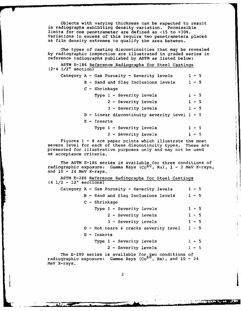
Objects with varying thickness can be expected to resultin radiographs exhibiting density variation. Permissiblelimits for one penetrameter are defined as -15 to +30%.Variations in excess of this require two penetrameters placedat film density extremes to qualify the area between.
The types of casting discontinuities that may be revealedby radiographic inspection are illustrated in graded series inreference radiographs published by ASTM as listed below:
ASTM E-186 Reference Radiographs for Steel Castings(2-4 1/2" section)
Category A - Gas Porosity - Severity levels 1 - 5
B - Sand and Slag Inclusions levels 1 - 5
C - Shrinkage
Type 1 - Severity levels 1 - 5
2 - Severity levels 1 - 5
3 - Severity levels 1 - 5
D - Linear discontinuity severity level 1 - 5
E - Inserts
Type 1 - Severity levels 1 - 5
2 - Severity levels 1 - 5
Figures 1 - 8 are paper prints which illustrate the mostsevere level for each of these discontinuity types. These arepresented for illustrative purposes only and may not be usedas acceptance criteria.
The ASTM E-186 series is available for three conditions ofradiographic exposure: Gamma Rays (Co6 0 , Ra), 1 - 2 MeV X-rays,and 10 - 24 MeV X-rays.
ASTM E-280 Reference Radiographs for Steel Castings(4 1/2 - 12" sections)
Category A - Gas Porosity - Severity levels 1 - 5
B - Sand and Slag Inclusions levels 1 - 5
C - Shrinkage
Type 1 - Severity levels 1 - 5
2 - Severity levels 1 - 5
3 - Severity levels 1 - 5
D - Hot tears & cracks severity level 1 - 5
E - Inserts
Type 1 - Severity levels 1 - 5
2 - Severity levels 1 - 5
The E-280 series is available for 6 wo conditions ofradiographic exposure: Gamma Rays (Co6 , Ra), and 10 - 24MeV X-rays.
31.. - . .

> A
w 00
In
V) -L-
-4-n 4-)
Wo 0 -
4-l~0 IfA
4i-) Q) 0)
4-- V
5-j Q) C4-1) 4
- u)
0) cC, a, 0
(1 S-
OS LU
- ~4-_ _4- - 0
* V 4-) LC)S-
*- 0
LU-A
h~S 0 0~IE)
U-0

'Io
Q) 4-
- L 4
LI) >0a) 4
0 Lfl
1>0- S).
(U t
-U a)
4J 4--a
.0 (U
Ur
4-I 4)e)a)
4--
-Io
co
LI) S.- to
4--o i
r_ Lfl (U0 i
4-) Q)
LnW
4 142
aS-
C) 0

) C~.
c 41
u 0
40)
V0)
Q4-4-
S- LA4)4J. L-
>0W
4-I )4-
0-
LU)
C4) a
0>0a
-- u
S- V)
LA 0D S-4-Q)4-*t0
In-A .C-
0b-(
.- S-.

1 c
6V 4-)L.) 4-
LO
4-) V) C"
4- L.)4-
0 1
r o a)-0 4)
-.- _V
4-) 0
to >S.--
+I)
I> m~cu 0
00 cin
Li.-
Lii
S-
to )
.- 00
VI) Lii LA)
o 'n- cz0V
4- 0
- (V
iV 1 4
4-3 L0)
- >- 0+4-' 1-
1.
-0
Li-

If reference radiographs are to be used as a means forcontrolling casting quality, it must be realized that they arenot in themselves a standard. Their use must be supplementedby contractual specifications setting forth the maximumacceptable level of severity for each type of discontinuityillustrated. In addition, this should be done for each sectionof the casting requiring radiographic inspection and for whichdifferent service requirements are recognized.
The severity levels for the types of discontinuitiesillustrated are not equivalent. Acceptance criteria basedupon ASTM Reference Radiographs should reflect separateconsideration for each type. For example, referencing E-186,maximum acceptable discontinuities regarding a specific partof the casting are as follows:
Category A - Gas Porosity - Severity level 4
B - Sand and Slag Inclusions level 3
C - Shrinkage
Type 1 - Severity level 1
2 - Severity level 2
3 - Severity level 2
D - Linear discontinuity none
E - Inserts
Type 1 - Severity level 4
2 - Severity level 4
It should also be noted that the size of the referenceradiograph is inherently a part of the acceptance criteria.As for example: Using a radiograph 5" x 7", then no 5" x 7"area of the casting radiographs can exhibit discontinuitiesin excess of that illustrated in the specified maximum levelseverity for that discontinuity type.
Ultrasonic Inspection. Ultrasonic inspection is beingused to control the quality of steel castings in both theUnited States and overseas. Long recognized as a valuablesupplementary tool to radiographic inspection, many foundriesand their customers now use ultrasonic inspection as the solenondestructive testing method for determining subsurfacecasting integrity.
When the ultrasonic method is to be used as a primarymethod for inspecting steel castings, procedure can becontrolled by specifying ASTM A-609, Longitudinal BeamUltrasonic Inspection of Carbon and Low Alloy Steel Castings.
This specification may be used contractually to establisha required quality level. It must be stated if the qualitylevel is to be for the entire casting or only for certainsections.
8

Examination is by the ultrasonic pulse-echo method usingthe longitudinal beam (straight) technique. Requirements areset forth regarding the ultrasonic instrument. It must becapable of generating frequencies between I and 5 MHz and havevertical linearity within + 5% for 75% of the screen height.A signal attenuator accurate to within 10% is also required.Primary inspection is to be done using either one inch squareor one inch diameter transducers.
Reference blocks containing flat bottomed holes are usedto establish the instrument sensitivity. The diameter of thehole is held constant at 1/4 inch but the blocks comprising theset vary in length from 1 - 10 inches with provision fortesting thicknesses gzeater than 10 inches.
The personnel performing the ultrasonic examination mustbe qualified, and general guidance in this regard is provided.Qualification to ASNT TC-lA is suggested but not required; but,a record must be kept of personnel qualification.
Any heat treatment for mechanical properties must be donebefore ultrasonic examination. There is a requirement for thecleaning of the casting surface.
The inspection of the casting is to be done at a rate notto exceed six inches per second and the transducer passes mustoverlap.
In some cases, it may be advantageous or necessary to usean angle beam technique. Proper procedure can be specifiedusing ASTM E-587-76, Standard Recommended Practice for UltrasonicAngle Beam Examination By The Contact Method. This recommendedpractice considers the ultrasonic examination of materials atangular incidence. Four types of waves are considered:Longitudinal, Shear, Rayleigh, and Lamb. The physics and methodsof generating each type of wave are set forth. In addition,attention is given to possible test complications which mightarise due to the coexistance of two different types of wavesunder certain conditions.
A calibration procedure is suggested utilizing the reflectionfrom a side-drilled hole. The diameter of the hole is notspecified and so must be described contractually. In regard toacceptance criteria, it is suggested that advance agreement bemade regarding interpretation and a rejection level.
In addition to these documents produced through code bodies,some foundries have created ultrasonic inspection proceduresdesigned to replace radiographic inspection of a stated severitylevel - usually with economic advantage. These procedures areinvariably proprietary and, therefore, not generally availableexcept on a case-by-case basis.
9

Castings are often complex in configuration and completeinspection done using ultrasonics may require innovativetechniques. Valuable guidance in this regard has beenprovlded in the following publications by technical societies:Ultrasonic Testing of Steel Castings, Steel Founders Societyof America, Rocky River, Ohio, June, 1976; Atlas of Some SteelCasting Flaws as shown by Non-Destructive Testing, Steel CastingsResearch and Trade Association, Sheffield, England, 1968.
Magnetic Particle Inspection. Steel castings may beinspected with the magnetic particle method. Proper procedurecan be assured for wet method using ASTM E-138, Wet MagneticpRrticle InsDectiofn. This standard method, applicable to allferromagnetic materials, presents techniques for the wet methodof magnetic particle inspection. It does not present or suggeststandards for the evaluation of indications obtained. It isrecognized though that evaluation is necessary and the recom-mendation is made that contractual agreement include theacceptance criteria. In addition, it further recommends thatthe contract specify the area to be inspected, the type ofmagnetizing current (AC or DC), the direction of the magneticfield, how many "shots" are to be used, the method of Magnetization(longitudinal, circular, over-all or local), the magnetizationcurrent or ampere turns to be used on each "shot" and the sequenceof operation (continuous or residual). It is stated that "Allof these techniques cause variations in results and must bestandar3ized if reproducible results are to be obtained uponwhich acceptance standards are to be based." The balance of this
standard method sets forth the principles of good practice.
If the dry method is to be used, the procedure can be controlled
usin ASTM E-109, Dry Powder Magnetic Particle Inspection. Thismeto considers all of the magnetizing procedures used in the wet
method and also includes, in addition, magnetization usingelectrical prods. As with the wet method, acceptance criteria isneither set forth nor suggested. Further, as with the wet method,this standard requires a specific agreement between the contracturalparties which accurately defines indications considered acceptableand those considered unacceptable - this in regard to type,location and direction.
The document reviews the equipment, materials and procedurerelated to good practice. Specific guidance is presented formagnetizing technique, direction of magnetization and the sequenceof operations. The requirements for adequate electrical currentare set forth in a table which considers both prod spacing andsection thickness.
Appendix 1 of ASTM E-109 presents Additional Procedures,which includes direct and indirect methods for accomplishlng over-all magnetization, techniques relating to longitudinal magnet-ization, the use of alternating current, the utilization ofresidual magnetization and procedures for demagnetization.
NOTE: ASTM E-109 and E-138 have been deleted and replaced by ASTM E-709.
10

Appendix 2 of ASTM E-109 includes Typical Indications.This is a set of reference photographs illustrating indica-tions on castings, welds, rolled or forged material and nonrelevant indications.
Difficulties are frequently encountered in attempts tocontractually specify acceptable or unacceptable conditions asrevealed by magnetic particle inspection. This has promptedASTM to assemble a set of reference photographs to provideassistance in this reqard. These are published as: ASTME-251-63. Reference Photographs For Magnetic Particle Indicationson Ferrous Castings. These reference photographs are applicableto ferromagnetic castings inspected by the dry powder magneticparticle method. By comparing the discontinuities revealed inmagnetic particle inspection with these reference photographs,specifications and/or acceptance criteria may be established.It is necessary to contractually state the limiting degree ofseverity and the locations to be inspected.
Five types of casting discontinuities are considered. Theseare: Linear discontinuities - five levels of severity, threeexamples each; Shrinkage - five levels of severity, one exampleeach; Inclusions - five levels of severity, one example each;Internal chills and chaplets - five levels of severity, oneexample each; Porosity - two examples.
In addition, reference photographs are included for weldswhich may be incorporated into the casting: One example eachof weld porosity, incomplete penetration, undercutting, inclusionsin the weld, and crater cracking.
Five examples are presented of false indications and fiveexamples are included of magnetic anomalies.
It is called to the users attention that there is nocorrelation or equivalency between the levels of severity of thevarious discontinuities.
Liquid Penetrant Inspection Method. If liquid penetrantinspection is to be used to inspect steel castings, properprocedure may be ensured through ASTM E-165, Ligid PenetrantInspection Method. This is a standard recommended practiceapplicable to nonporous metallic materials suited to the detectionof discontinuities which are open to the surface, such as cracks,seams, laps, coldshuts, laminations and lack of fusion.
Standards for evaluating indications are neither indicatednor suggested. Therefore, contractual agreement must includespecifications defining the type, size, location, and directionof indications considered acceptable and unacceptable. Further,a "strong recommendation" is made that the specific techniquesbe a part of the agreement.
Fluorescent and visible liquid methods are considered. Foreach of these, three subgroups are recognized: water-washable,post-emulsifiable, and solvent-removable. Procedures relating togood practice are set forth for each.
' 11
'S|

A cautionary note is included regarding the sulfur andchlorine content of the penetrant inspection materials. Insome cases, the parts tested may be adversely affected.Limitations on these substances may be an essential part ofthe contractual agreement.
The description of indications as revealed by penetrantinspection can be difficult. Some assistance is availablethrough reference photographs in ASTM E-433, Liquid PenetrantInpection. This standard is a set of reference photographs ofsurface discontinuities revealed by liquid penetrant inspection.Although no attempt has been made to establish limits ofacceptability, it is stated that these photographs may be usedas a reference in specifications or acceptance standards. Suchuse must be supplemented by limitations on actual discontinuitylength and the number of indications acceptable per unit area.
The reference photographs recognize a distinction betweenindications for which neither of the measurable dimensions isthree times greater than the other and indications for whichthis is true. For each category four subgroups are presented:Single, Multiple Unaligned, Multiple Aligned and the Intersectionof surfaces such as corners or fillets.
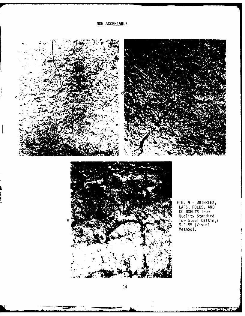
Visual Insection. The Manufacturers Standardization Societyof the Valve and Fittings Industry have developed visual stand-ards for evaluating steel castings: S-P-55, 1971 edition(reaffirmed 1975), guality Standard For Steel Castings For Valves,Flanges and Fittinas and Other Piping Components (Vigual Method).Figure 9 whic illustrates the surface conditions wrinkles, laps,and coldshuts , is an example of the visual standards set forthin this document.
These standards illustrate steel casting surface conditionsthat may be evaluated visually. Twelve categories are presentedin five gradations of severity with suggested degrees ofacceptability:
TYPE 1: HOT TEARS AND CRACKS, Linear surface discontinuitiesor fractures caused by either internal or external stresses ora combination of both acting on the casting. They may occur duringor subsequent to solidification. In general, visible surfacecracks and/or hot tears are not acceptable.
TYPE 2: SHRINKAGE, A void left in cast metals as a resultof solidification shrinkage and the progressive freezing ofmetal which is exposed upon cutting off risers and gates.
1. Reproduced by permission of the Manufacturers StandardizationSociety of the Valve and Fittings Industry, 1815 North FortMyer Drive, Arlington, VA 22209.
12
.. . . . i .. .. . .. . .* - - -

m LM
LA_. 0
LU Va M
LU toX
M-J 0~
O~E I
im4
LL_
13
Row AL 7'
NON ACCEPTABLE
C.
.tt FIG. 9 -WRINKLES,LAPS, FOLDS, AND
'~COLOSHUTS from.X Quality Standard
e for Steel CastingsS-P-55 (VisualMethod).
14
TYPE 3: SAND INCLUSIONS, Sand which becomes entrapped inthe molten metal and shows on casting surfaces.
TYPE 4: GAS POROSITY, Voids in cast metal caused byentrapment of gas during solidification.
TYPE 5: VEINING, Features on the surface of castingsappearing as a ridge and associated with movement or crackingof sand.
TYPE 6: RAT TAILS, Features on the surface of castingsappearing as a depression resulting from faulting or bucklingof the mold surfaces.
TYPE 7: WRINKLES, TAPS, FOLDS AND COLDSHUTS, Surfaceirregularities caused by incomplete fusing or by folding ofmolten metal surfaces.
TYPE 8: CUTTING MARKS, Irregularities in casting surfacesresulting from burning or mechanical means used in the cleaningof castings.
TYPE 9: SCABS, Slightly raised surface blemishes which areusually sand crusted over by a thin porous layer of metal.
TYPE 10: CHAPLETS, Evidence of chaplets on surface ofcasting disclosing incomplete fusion, which likewise can aplyto ifternal chills.
TYPE 11: WELD REPAIR AREAS, Evidence of improper surfacepreparation after welding.
TYPE 12: SURFACE ROUGHNESS, Surface texture due to design,pattern, gating and sand conditions.
NONDESTRUCTIVE INSPECTION OF STEEL FORGINGS
Radiograghic Inspection. The forging process squeezes shutvolume-type discontinuities within cast material and flattensout foreign material such as slag. Laminations related to theseconditions have narrow dimensions which are unfavorable todetection by radiography. Similarly, cracks must be unfavorablyoriented for detection. Consequently, radiography should notbe used as a primary tool for forging evaluation.
Ultrasonic Inspection. Ultrasonic inspection is an excellenttool for examining heavy forgings. However, its use as a primaryinspection method does require assurance of proper procedure.This can be accomplished by specifying ASTM A-388, UltrasonicExamination Of Heavy SteelForg~inqgs This recommended practicecovers both straight beam and angle beam techniques for theexamination of heavy steel forgings.
15
S- .17

This is to be done with the pulse-echo reflection typeinstrument. A nominal frequency of 2 1/4 MHz is recommendedwherever practical. However, for course grained materials,1 MHz is permitted and a frequency as low as 0.4 MHz isacceptable for difficult to penetrate materials such asaustenitic steel. The active area of the transducer is re-stricted to a maximum of 1 square inch for straight beam workand either 1" x 1" or 1" x 1/2" for angle-beam scanning.
Approved couplants include: water, glycerin, motor oil,or pine oil, but it is cautioned that coupling characteristicscan be expected to differ aid consistency must be maintainedbetween the calibration procedure and the actual work. Thisis emphasized in a graph in that appendix in which the signalamplitude from reference reflectors is plotted against surfacecurvature. The curve for oil and glycerin differ significantly.
Requirements are set forth for instrument linearity regardingsignal amplitude. This is to be done using approved referenceblocks containing flat-bottomed holes. The same blocks are tobe used to establish the instrument sensitivity for scanningthe work material.
The surface to be inspected must be free of extraneousmaterial such as loose scale or dirt and the surface roughnessis not to exceed 250 u inch unless so stated in the contract. Ifthe forging is to be heat treated,then examination is to be doneafter that is completed.
In performing the ultrasonic examination, a 15% overlap ofpasses is required at a scanning rate not to exceed 6 in./sec;andif possible,at two perpendicular directions. Guidance ispresented for the scanning technique to be used on forgings ofspecific geometry-cylinders, hollows, etc.
As an alternate to calibration using reference blocks, atechnique is presented whereby for straight beam examination, thereflection from the back surface can be set at 75% of full-screenheight and sensitivity can then be increased by using the decibelattenuator. If the forging thickness changes, recalibration is
required.
During examination of the forging, in addition to monitoringsignals from within the forging volume, the operator is requiredto also monitor the reflection from the back surface. This isdone because a signal reduction may be indicative of flaws andalso could alert the operator to conditions of poor coupling ornonparallel surfaces.
For angle-beam scanning, a 450 angle-beam search unit isrecommended and calibration is to be done on a rectangular or600 "V-notch" cut 3% of the nominal thickness or 1/4" whicheveris smaller. Rings and hollow forgings are to have a notch onboth surfaces and a reference level curve is to be constructedto compensate for attenuation and beam scatter: Sensitivity isset by adjusting the signal from the reference notch on the backside to 75% of full-screen height.
16

It is stated in this recommended practice that forgings aretoo diverse to establish a universal quality level, and thatacceptance criteria should be based upon a realistic appraisalof service requirements.
Guidance is provided, however, in two separate ways: First,,certain type indications are to be recorded. These include(1) signals 10% the amplitude of the back reflection signal orthose equal to or in excess of 100% of the reference amplitudeobtained using the calibration block, (2) indications continuouson a plane, (3) indications which travel with motion of thesearch unit, (4) clusters of indications, (5) reduction in backreflection signal amplitude exceeding 20% of the originalamplitude, (6) for angle beam examination - any signal 50% orlarger than the reference line. Second, it is suggested thatacceptance be established based upon one or more of the followingcriteria: (1) a limit on signal amplitude expressed as apercentage of the back reflection, (2) a limit on signalamplitude expressed in relation to the signal amplitude obtainedin calibration using a reference block, (3) a limit on thereduction in signal amplitude of the back surface reflection -expressed as a percentage, (4) a combination of signal amplitudeand reduction in back surface signal amplitude, and (5) for anglebeam examination - a limit on signal amplitude expressed as apercentage of the reference line.
Magnetic Particle Inspection. Steel forgings may also beinspected for disconitnuities open to the surface using eitherthe wet or dry method of magnetic particle testinq. Procedurecan be controlled by specifying ASTM A-275, Magnetic ParticleExamination Of Steel Forginqs. This standard method considersboth wet and dry magnetic particle testing of steel forgings.It provides procedural guidance constituting good practice forthe continuous, surge, and residual methods of magnetization andthe two general types of magnetization, longitudinal and circular.It requires that two approximately mutually perpendicularexaminations be conducted separately on each area.
This standard does not present any acceptance standardsand does not define any quality levels. However, it statesthat standards for acceptance shall be specified in the contractor order.
Although acceptance criteria is not set forth, thisstandard does define and describe the types of indications whichmay be obtained. These are grouped into three broad categories:(1) surface defects such as forging laps and folds, laminar
defects, flakes, and cracks due to heat treating, shrinkage,grinding, and etching or plating; (2) subsurface cracks such asstringers of nonmetallic inclusions, large nonmetallics, cracksin the underbead of welds and forging bursts; and (3) nonrelevantindications such as magnetic writing, changes in section, weldedges and flow lines.
17

Nonrelevant indications must be resolved by other methodsof nondestructive testing and demonstrated nonrelevant oreliminated by surface consitioning. Since subsurface indicationscannot be found using alternating current, and if this typeof discontinuity is of importance, the use of methods employingdirect current must be specified. Criteria for evaluatingdiscontinuities should be based on size, number, location andfor linear indications the length and direction.
Use of this standard is to be supplemeted by the previouslymentioned E-183-63 and E-109-63 which consider the wet and drymethods of magnetic particle inspection.
Liquid Penetrant Inspection. While magnetic particleinspection is a superior and faster way to inspect steel forgings,liquid penetrant testing can be done and involves the samestandards and procedures previously set forth for castings.
Visual Inspection. If surface texture is important, theAmerican National Standard ASNI B46.1 Surface Texture can beused for this purpose.
NONDESTRUCTIVE INSPECTION OF THICK WELDS
Radiography. The quality of radiography for steel weldsis controlled using the same specifications E-94 and E-142,previously discussed under the radiographic inspection ofsteel castings. Discontinuities revealed by radiography canbe evaluated using ASTM E-390, Reference Radiograph s For SteelFusion Welds. Volume II is applicable to welds between 1 1/2"and 3". Volume III is for welds 3" - 8" thickness. Table 1lists the types and number of grades of severity in each volume.
As with the casting reference radiographs, these are notstandards in themselves; however, they can be used to createacceptance criteria by contractually specifying a maximumacceptable grade of severity for each type discontinuity. Forexample, referencing ASTM E-390, the maximum permissible severitylevel for each type discontinuity in a weld of 2 1/2" is asfollows:
Fine Scattered Porosity Grade 4
Coarse Scattered Porosity Grade 3
Clustered Porosity Grade 4
Linear Porosity Grade 1
Elongated Porosity None
Slag Inclusions Grade 2
Tungsten Inclusions N/A
Incomplete Penetration Grade 1
Lack of Fusion Grade I
Burn Through None
Icicles None

Cracks None
Undercut None
Ultrasonic Inspection. The ultrasonic method can be usedon thick welds with advantage. The ordinary angle beam method,slightly modified, is applicable and in addition that inspectioncan be complemented using the straight beam. The procedure,however, is more complex with thick welds and should becontrolled in accordance with ASTM E-164, ULTRASONIC CONTACTEXAMINATION OF WELDMENTS. This standard recommended practice isapplicable to welds up to eight inches thickness using eitherstraight beam or angle beam techniques. Personnel performingthe ultrasonic examination should be properly trained. SNT-TC-1Ais referred to for qualification.
No acceptance criteria is presented and it is left tocontractual agreement to establish calibration standards.
The ultrasonic instrument used for weld examination shouldhave an "A-scan" presentation and a capability for generatingthe recommended inspection frequencies of 1.0 - 5.0 MHz.Quantitative evaluation of flaws requires the instrument to haveeither a linear amplifier, calibrated gain control or a distancecompensating amplifier. There are requirements for horizontallinearity.
Search units as small as 1/4 inch diameter are recognizedas suitable for some applications and sizes as large as 1 1/8inch diameter are permitted. For shear wave inspection,rectangular probes having a length to width ratio greater thantwo are not recommended.
Shear wave angles are not specified, but a table is setforth whereby optimum angles are correlated with various basemetal thicknesses. The nominal angle indication on the trans-ducer wedge should be checked to avoid erroneous conclusionsregarding discontinuity location. Two methods for accomplishingthis, the polar coordinate and rectangular coordinate, arepresented in an annex to ASTM E-164.
Calibration is considered in detail. A procedure ispresented for determining the actual distance traveled. Thisis necessary in order to accurately locate discontinuities. Anequal angle reflecting surface, incorporated into certain testblocks, is recommended, but this may also be done utilizing thereflection from a notch. Test blocks with side-drilled holes(illustrated in an annex) are useful for performing distance,amplitude, position and depth calibration. In addition, thistype of test block can be used to determine the relation betweendepth or distance traveled and signal amplitude fluctuations.This is to be done either by constructing a curve on theoscilloscope screen or with instruments so equipped, using thedistance - amplitude controls to obtain signals of equal screenheight from all depths within the test range.
19
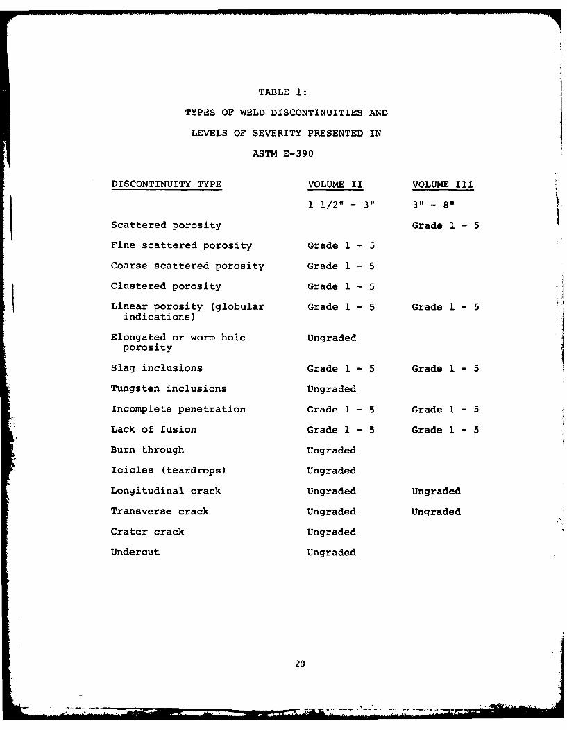
TABLE 1:
TYPES OF WELD DISCONTINUITIES AND
LEVELS OF SEVERITY PRESENTED IN
ASTM E-390
DISCONTINUITY TYPE VOLUME II VOLUME III
1 1/2" - 3" 3" - 8"
Scattered porosity Grade 1 - 5
Fine scattered porosity Grade 1 - 5
Coarse scattered porosity Grade 1 - 5
Clustered porosity Grade 1 - 5
Linear porosity (globular Grade 1 - 5 Grade 1 - 5indications)
Elongated or worm hole Ungradedporosity
Slag inclusions Grade 1 - 5 Grade 1 - 5
Tungsten inclusions Ungraded
Incomplete penetration Grade 1 - 5 Grade 1 - 5
Lack of fusion Grade 1 - 5 Grade 1 - 5
Burn through Ungraded
Icicles (teardrops) Ungraded
Longitudinal crack Ungraded Ungraded
Transverse crack Ungraded Ungraded
Crater crack Ungraded
Undercut Ungraded
20

It is recognized that there may be coupling differencesbetween the test block surface and that of the work piece.A test block with surface roughness equivalent to that of thework would circumvent the difficulty but may not be feasible toprepare. Alternatively,a transfer technique may be used.This procedure utilizes a notch in the basic calibration blockand a similar notch machined into the weld seam. The ratioof signal amplitude from these two notches permits adjustmentof instrument sensitivity to achieve a valid calibration foruse on the work piece. All of the calibration procedures andtest blocks are described in detail in the test and annex.
When longitudinal waves (straight beam) are used in weldinspection, the calibration procedure is essentially identicalto that for shear waves. It is pointed out,however, that if
both methods are used and it is desired to have equivalent wavelengths within the test material, the longitudinal probe shouldbe a frequency about double that of the angle probe.
This recommended practice is limited to specific weldgeometries: Butt weld, "Tee" joints and corner joints. Bothflat and curved surfaces are considered and specific inspectionprocedures are set forth for each.
Several techniques are suggested for discontinuity evaluation:signal amplitude can be used to measure defect severity, but itis emphasized that this should be based on experience with actualdefects and not artificial reflectors; discontinuity dimensionscan be determined locating the points where signal amplitudefalls to one half; orientation can be deduced from relativesignal amplitudes obtained by altering the direction of inspection;and reflector shape may be deduced from the relative sharpnessof the signal.
The determination of discontinuity dimensions, orientation and
shape may be useful but should not be a basis for acceptancecriteria because of the great dependence on operator skill.
Magnetic Particle Inspection. The magnetic particle methodmay be used to inspect welds for discontinuities open to thesurface before more sophisticated techniques are used. It canalso be valuable for verifying complete defect removal prior torewelding.
With the exception of the electrical current requirements,the technique for inspecting welds with magnetic particles isindependent of the thickness. Good practice is set forth in thepreviously discussed document E-109.
Technical details involvin he magnetic particle inspectionof welds are presented in Welding Inspection of the AmericanWelding Society and in SSC-253, A Guide for the NondestructiveTesting of Non-Butt Welds in Commercial Ships - Part One.
21
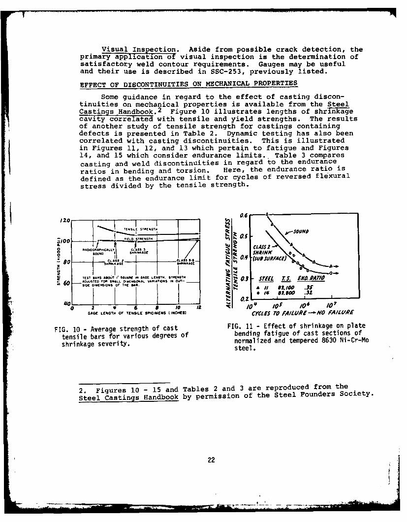
Visual Inspection. Aside from possible crack detection, theprimary application of visual inspection is the determination ofsatisfactory weld contour requirements. Gauges may be usefuland their use is described in SSC-253, previously listed.
EFFECT OF DISCONTINUITIES ON MECHANICAL PROPERTIES
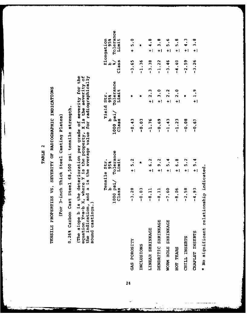
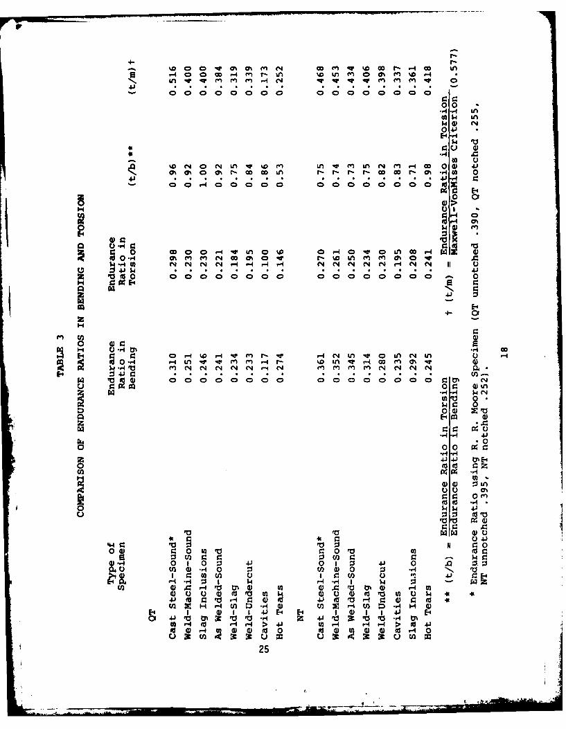
Some guidance in regard to the effect of casting discon-tinuities on mechanical properties is available from the SteelCastings Handbook.2 Figure 10 illustrates lengths of shrin-kagecavity correlated with tensile and yield strengths. The resultsof another study of tensile strength for castings containingdefects is presented in Table 2. Dynamic testing has also beencorrelated with casting discontinuities. This is illustratedin Figures 11, 12, and 13 which pertain to fatigue and Figures14, and 15 which consider endurance limits. Table 3 comparescasting and weld discontinuities in regard to the enduranceratios in bending and torsion. Here, the endurance ratio is
defined as the endurance limit for cycles of reversed flexural
stress divided by the tensile strength.
I zC ... ~j ~ ~F1ff~zfU~i M ~y6c:. %A
O FiA(O= N .HCALLY CASSIII 3Gvy
0o~ 1 Z 04,o • NS RAAC11" 0 L D S2 -d1 t~ .CLASS 2 ___ - CAS 9__4-_ I.
S.RI KA6G f 1.INKAGr
TEST MAPS A117I SQUARE IN As su G. •wU.rlF6 - J ED FOR ALL DENSIONAL VARIATIONS 0ft OUT-
SIDE DIMENSIONS Of TME SA Jif LII 3.10 .31
Mo~ I.. .
0 2 6 e to 12 /0~ O O 0GAGE LENGTM OF TENSILE SPICIMENS (INCHES) CYCLES To fAIL URE-"NO FAIIURE
FIG. 10 - Average strength of cast FIG. 11 - Effect of shrinkage on plate
tensile bars for various degrees of bending fatigue of cast sections of
shrinkage severity, normalized and tempered 8630 Ni-Cr-Mosteel.
2. Figures 10 - 15 and Tables 2 and 3 are reproduced from the
Steel Castings Handbook by permission of the Steel Founders Society.
22
6 .-. ,-

-CAST STEL - %M"O--(DDMAME-SOnA.WILD s- UCOMPLIT'E wiugmHAiiaAS WS.MG-mOUuS
0 o ~*-WCLS-SIAGS--SLAS NCLUSION3O: -1- WLO-WLOMCUT-A- "OT TEARS
a- CNAT35
5- LAS 5111.-CAS SIM oulA LSOL"S
-5-OT ILA"%\ -0 IL:...Q4 - -A- SLAG WCLUSIOS
03 -0
-SaIM4 PA .. NOAK
Q2V i tsLOS--b.-.p-i.
to'Jo a,, CYCLES To FAUIRCWCLES 70 FALURE
FIG. 12 -Bending fatigue for FIG 13 -Torsion fatigue for normalizednormalized and tempered 8630 cast and tempered 8630 cast steel con-
steel containing surface dis- taining surface discontinuities.
0. SO 110.4O
t4~ 0.30
~g0. 25
T0.2
0 2 6'86a/PERCENT: SEION AREA Of SHRINK CAVITYr 0/ 03 or~ I 23Of /0
SECTON AREA OFSPECIA*IEN DIAMETE Of POROSITY, am
FIG 14 - Endurance limnit in pulsating FIG 15 - Relation between diameter oftension testing for cast steel surface gas cavities and thesections containing shrinkage endurance ratio for 0.20 percentcavities, carbon cast steel.
23
-6. --Z ilil"111, -1m r -A
dp to4j 0 Go 0 %D CI (n OD0 LA I..4 * *H
41 -4% LA *eP4 U . V
to0 o. + +1 +1 + +1 +1 +
0111-4 '.02I LA %0 CI N %0 0 0% wD
dP.QU M D %0% m~ en qv Ln C40
ri~ ~ 4 9 4 4 4 4 9
.4 0r-I41' -4
>4 0 U
z -4 -4 to41' M 0 IN 0 cis0 '44 W. $4 54rj
) 004 w d0 (L a N9 49 (4 14 (4 C4 ->1 > 10 41 Unr-4 w.44j 14) - U N04O +1 + +1 +1 +
Li00H 042 4 ~I 0% #0~0 -
* 0 04 m en () %002n n w PH 4 4 44 -P4 N4IN 0 r - I 0 C4 0 %
01 4J 0~ 0 coI m000t~ .*-
W 10 4
H4 P4 M $ .Q 0
M M 0400 z04-1 D 0 4
0 i r-40'p
-1 >4 00 H i4 HP H H
U) 0 tN r- -r4*n $40 1 ~ M )0 +++++
Al 0 -q 00) E-4 H (2 12 12 44
E-4E- r-1 4j ) r-
4) 24
F- .)CD m r4 r- D 0 --
.4- -
9 W 00 O Q M C' f- 0-H w m o mno
N n v v~ mM m m P-A N v vM v 0
00000 00 00 0000004 -r
0 V
* *4 .C
ko (40 N in IV%0M in qw m n c%4 m r- co0a 41cra% 5 cs . a coLnr- r- OD00ro -4C 0
001
$~4 O (
-H to N N '.Oi -4P N N N N O- N
4J $44.)2 p tUo 00 00 0 00000000;C;C ; ; C;C C ;C 0H C:0:E4
4.)
E-4
H '4 *sr4 co
N 0 0 rI% -44 n r -W4ir-4 c4' H Ln v0 In c.,4 0 '-A -iIVv Mn fn r- f-. W~ MM MM r4 00 M~ a% "
$4 VO4 00 00 0 00 00 0 N 1 n nN(E- 01 WI"r
(n 00 *0
0 44) z Eo
o o0 0-H *r
0 0 O
V~ VVN0
tJ 0 4 1w U 43 4)
:3U . r. W 10 En~ -G H4WOO 0 W0 4V 100 .0 0
U n4) -r4 0 :3 W 0V'4 0 0 ., 1,*
E- 4 -I W 1 $ 4 E-' 1 I w4 :3-0- ot 4) O0VV a 4)VrVIr4 l
ir4 0 w ) 0 It) OA UH 0410 .4 -G 9 0 V0 V W OH4
0 3 ra i4 z 41 C : a A

SUMMARY AND CONCLUSIONS
Code bodies, notably ASTM, have produced procedural guides,standard methods and recommended practices which can be used toassure proper inspection procedure for the various methods ofnondestructive testing. These are applicable to heavy steelcastings, forgings, and weldments. In addition, ASTM offersreference radiographs and reference photographs, which may beused in contractual agreements. In the specific case of steelcastings, ASTM defines several levels of quality for ultrasonicinspection. However, these documents do not set forth acceptancecriteria or offer recommendations in that regard.
Discontinuities found by nondestructive testing must beevaluated and the ASTM documents discussed in this report doprovide guidance in this regard. This is done by describing theparameters which are generally agreed to be of significance andwhich should be a part of the contractural agreement. It is leftto the user to quantify these parameters according to servicerequirements or other considerations.
26 *V.S. G(WERNMENT PRtNT Fl I - I

I