for john deere - cozy cab john deere x700, x720, x720se, x724, x728, x728se, x729, x740, x744, x748,...
TRANSCRIPT

CAB MOUNTING INSTRUCTIONS John Deere X Series
05-11107_JDX_CAB_A-11762.doc 9/7/2010
FOR JOHN DEERE
X700, X720, X720se, X724, X728, X728se, X729, X740, X744, X748, X748se, X749 SERIES MODELS (Also fits X465, X475, X485, X495, X575, X585, X595)
A-11762 ROPS CAB KIT WITH TEMPERED GLASS DOORS
Page 1 of 26
CAB MOUNTING INSTRUCTIONS John Deere X Series
05-11107_JDX_CAB_A-11762.doc 9/7/2010
SAFETY INSTRUCTIONS Read operator’s manual. Be thoroughly familiar with the controls, capabilities, and proper use of the equipment. NEVER ALLOW ANY RIDERS. Thoroughly inspect cab mounting periodically. Stay alert for hidden hazards and traffic. Avoid sudden starts, excessive speeds, and sudden stops when operating on hillside, rough ground and most off-the-road operations. Use extreme care when working close to fences, ditches, or on hillsides. Wait for tractor to STOP before dismounting. Check clearance carefully before driving under any objects. Avoid operating sideways on a steep slope whenever possible. ALWAYS buckle safety belt while operating tractor. Never exceed factory recommended specifications. DO NOT weld, cut, drill or modify ROPS in any manner unless instructed by manufacturer.
Page 2 of 26

CAB MOUNTING INSTRUCTIONS John Deere X Series
05-11107_JDX_CAB_A-11762.doc 9/7/2010
ROLLOVER MAY CAUSE PERMANENT INJURY OR DEATH. ROPS RAISES THE CENTER OF GRAVITY AND REDUCES STABILITY ON SLOPES. SUDDEN STARTS OR TURNS ON RAMPS OR SLOPES CAN CAUSE OVERTURN. USE GREATER CARE ON RAMPS AND AS SLOPES INCREASE.
INSTALLATION INSTRUCTIONS FOR ROLLOVER PROTECTION SYSTEM (ROPS)
This manual contains assembly, operating, maintenance and safety instructions for your ROPS. Before Installing the ROPS or operating a machine equipped with a ROPS, carefully read these instructions completely. The ROPS will reduce the risk of serious or fatal injury in the unlikely event of a tip over although the system cannot protect the operator from all possible injuries. By following the operating, maintenance, and safety instructions, you will prolong the life of the machine and the ROPS, maintain its maximum efficiency and promote safe operation. If additional information is needed, contact your authorized equipment dealer or distributor. Keep this manual with the machine operator’s manual for future reference. IMPORTANT: 1. Do not cut, drill, modify or repair ROPS in any manner. 2. Always replace a damaged ROPS. 3. Always use the seatbelt and ROPS together. 4. Frequently inspect roll bar and seat belts for damage or loose hardware. 5. Use extreme care when working close to fences, ditches, trees and on hills. 6. Check overhead clearances carefully before driving under any objects. 7. Do not leave operator’s position while unit is running. 8. Do not carry riders. 9. If ROPS is a folding ROPS, ROPS should be in the upright position and pinned when
operating the machine.
WARNING! This ROPS is certified for use on machines with a maximum gross vehicle weight (GVW) of 2430 LBS. The GVW INCLUDES the weight of the base machine, operator, fuel, ROPS, and other attachments and payloads. When attachments are added, causing the GVW of the machine to be more than 2430 LBS., the ROPS may not provide adequate protection resulting in serious injury or death. Use caution when installing attachments and DO NOT EXCEED the GVW rating of the ROPS.
WARNING! SERIOUS INJURY OR DEATH MAY RESULT FROM MACHINE
ROLLOVER
• DO NOT OPERATE MACHINE ON STEEP SLOPES OR
NEAR DROP OFFS • ALWAYS USE SEAT BELTS • AVOID SHARP AND/OR QUICK TURNS • DO NOT EXCEED THE MACHINE WEIGHT RATING OF
THE ROPS
WARNING
Page 3 of 26

CAB MOUNTING INSTRUCTIONS John Deere X Series
05-11107_JDX_CAB_A-11762.doc 9/7/2010
Read these instructions and id entify all components. Plea se retain these instructions for future reference and parts ordering information. Refer to kit components and figure 1 for general layout. Kit Components:
Figure 1 (General Layout -Doors not shown)
ITEM 1
ITEM 5
ITEM 4 ITEM 3
ITEM 2
ITEM 7 (BEHIND WINDOW)
ITEM 6
ITEM 8
ITEM 9
ITEM QTY PART No. DESCRIPTION 1 1 A-11762 CAB ASSEMBLY, WITH GLASS DOORS 2 1 4-15431 REAR MOUNT ASSEMBLY 3 1 2-15706 FRONT MOUNT WELDMENT 4 1 2-15707 FRONT MOUNT RETAINING BRACKET 5 1 4-15484 FUEL ACCESS COVER ASSEMBLY 6 1 4-14673 VINYL RH AIR INTAKE COVER 7 1 1-47016 AIR COVER MOUNT BAR 8 1 4-15527 STEEL LH AIR INTAKE COVER 9 2 1-46936 LIFTING EAR
10 1 4-15469 HARDWARE KIT CONSISTS OF ITEMS 10-22 11 3 3-10379 HEX NUT, 1/2" NYLOCK 12 6 3-10147 HEX BOLT, 3/8" x 1.00" LONG 13 6 3-10086 FLAT WASHER, 3/8" 14 6 3-17622 FLANGE NUT, 3/8" 15 1 3-10141 HEX BOLT, 1/2" x 3.50" LONG 16 3 3-10087 FLAT WASHER, 1/2" 17 2 3-10406 HEX BOLT, 1/2" x 1.25" LONG 18 6 3-10228 HEX BOLT, 5/16" x 1.00" LONG 19 8 3-10085 FLAT WASHER, 5/16" 20 6 3-17111 FLANGE NUT, 5/16" 21 1 05-11107 MOUNTING INSTRUCTIONS, CAB A-11762 22 2 3-18798 SOCKET-BUTTON HEAD BOLT, 5/16" x 7/8" LONG
Page 4 of 26

CAB MOUNTING INSTRUCTIONS John Deere X Series
05-11107_JDX_CAB_A-11762.doc 9/7/2010
Preparation of tractor: 1) Open mounting kit box and layout parts. Refer to figure 1 for parts identification and
part numbers. 2) Remove the (4) carriage bolts from each side of the rear frame. See figure 2. Note:
Bolts are not present on all machines. 3) Removal of the mower deck is optional. It is easier to install the front mount tube with
the deck removed. Open the tractor hood. Installing Mounts: 4) Locate lifting ears (Item 9), supplied with cab kit. Secure (1) lifting ear to each side of
cab as shown in the figure below using (1) 5/16” x 1” bolt with each ear. 5) Using an overhead hoist, raise the cab using the lifting ears and remove the shipping
pallet and crating.
Figure 2 Figure 3
ITEM 4
STEP 6
STEPS 4 & 5
Page 5 of 26

CAB MOUNTING INSTRUCTIONS John Deere X Series
05-11107_JDX_CAB_A-11762.doc 9/7/2010
6) Attach the front mount retaining bracket (Item 4) to RH side of tractor frame under foot
deck area. Secure to frame using (2) 3/8 x 1.00” bolts, (2) 5/16” flat washers and (2) 3/8” serrated flange nuts. See figure 4.
7) Remove front mount tube (Item 3) from cab. Set hardware aside for re-use in Step 14. Insert tube into tractor frame. Use a 1/2 x 3.50” bolt with a ½” flat washer and a ½” nylock nut to secure tube to front mount retaining bracket. See figure 4.
Installation of Cab: 8) With cab raised, tractor can be rolled under cab and lowered. The cab is shipped with
the rear mount attached to back of cab and can be install without removing from cab. Tractors with 3-point assemblies may need the 3-point assembly removed in order to install rear mount.
9) Lower cab with rear mount onto the tractor’s rear frame. Cab may need to be tilted rearward to clear fender. Tilt forward and align with rear mount holes. See Figure 5.
10) Use a 1/2 x 1.25” bolt with ½” flat washer and ½” nylock nut on the lower hole on each side of the mount. See figure 6. DO NOT TIGHTEN UNTIL ALL HARDWARE IS INSTALLED.
Figure 4
Figure 5
Item 3
STEP 7
Figure 6
STEP 9
STEP 10
STEP 11 STEP 12
Step 6 Item 4
Page 6 of 26

CAB MOUNTING INSTRUCTIONS John Deere X Series
05-11107_JDX_CAB_A-11762.doc 9/7/2010
11) Use (2) 3/8 x 1” bolts with 5/16” flat washers and 3/8” serrated flange nuts on the (2)
front holes on each side of the mount. See figure 6. 12) Use (2) 5/16 x 1” bolts with 5/16” flat washers and 5/16” serrated flange nuts on the (2)
rear holes on each side of the mount. See figure 6. 13) Line up the front holes of cab with the front mount tube holes. 14) Secure the front of the cab with hardware from Step 5 by re-using (2) ½” x 3.50” bolts
and (2) ½” lock washers as shown in figure 7. 15) Remove lifting ears and store for future use if cab is ever removed. 16) Important! Using a torque w rench, torque all mounting hardw are to the
following torque specifications: 5/16” hardware to 21 ft-lbs 3/8” hardware to 37 ft-lbs 1/2” hardware to 90 ft-lbs
17) Check the ½” bolts that connect the cab ROPS to that rear mount are properl y torque to 90 ft-lbs! See Figure 8.
Electrical Hook-Up (Disconnect battery power): 18) Open the windshield and lift the tractor hood. Remove the right side screen assembly
from the tractor console. Disconnect battery. Locate relay-breaker end of wire harness (secured to LH front post of cab for shipping from factory).
19) Gas engines, only; Attach the relay breaker mount bracket to tractor. Remove the lower mounting screw from the muffler guard on left side of the tractor. Attach bracket and ¼” ring terminal on 12” black ground wire from relay using mounting screw for muffler guard. See figure 9.
20) Diesel engines, only; Mount relay breaker mount bracket, supplied to the lower right side of machine frame along with the black 12” black ground wire. See figure 10.
Figure 7 Figure 8
STEP 17 STEP 14
Page 7 of 26

CAB MOUNTING INSTRUCTIONS John Deere X Series
05-11107_JDX_CAB_A-11762.doc 9/7/2010
21) Route the 66” blue wire from relay PIN 86 to the tractor’s electrical panel, located on
left side of cowl. Use a 3-way wire splice or T-tap connector to connect the blue wire to yellow #500 wire. See figure 11.
22) Connect the 3/8” ring terminal on the 8” orange wire from the circuit breaker to the (+) positive post on the starter motor. See figure 9. Gas engine shown – diesel engine similar.
23) Secure loose wire harness with nylon ties to avoid any hot or moving parts.
Figure 9 (Gas engines, only)
Figure 11
Figure 10 (Diesel engines, only)
STEP 21
STEP 19
STEP 22
STEP 20
ITEM 24
BLUE WIRE FROM RELAY PIN 86
YELLOW #500 WIRE
STEP 32
Page 8 of 26

CAB MOUNTING INSTRUCTIONS John Deere X Series
05-11107_JDX_CAB_A-11762.doc 9/7/2010
Installing Seal Panels (REMOVE PANELS FOR SUMMER USE). 24) Install air intake mount bar (Item 7) as shown in Figures 12 & 13. Secure the top of
bar by using the inside window bracket hardware. 25) Secure the bottom of mount bar using (1) 5/16” x 7/8” long socket-button head bolt
and (1) 5/16” flange nut. 26) Place LH air intake panel (Item 8) around the tractor cowl area. Secure panel to
mount bar installed in step 22, using (1) 5/16” x 7/8” long socket-button head bolt and (1) 5/16” flange nut.
27) Clean surfaces of the RH side of the tractor’s cowl using isopropyl alcohol. 28) Matching the angle of the intake cover’s edge, apply the PSA Velcro hook located on
the RH inside surface of the steel air intake panel (Item 8) to the machine’s cowl surface. See Figure 14.
29) Locate vinyl RH air intake cover (Item 6). Peel and stick Velcro hook with PSA back, onto RH side of cowl panel and the side of the machine’s step panel as shown in figures 14 and 15. Make sure pedal operates freely from the vinyl cover. See figure 15.
Figure 13 Figure 12
STEP 26
STEP 26
STEP 24
STEP 25
ITEM 8
STEP 25
STEP 24
ITEM 8
ITEM 7
Page 9 of 26

CAB MOUNTING INSTRUCTIONS John Deere X Series
05-11107_JDX_CAB_A-11762.doc 9/7/2010
30) Reconnect battery. 31) Turn ignition key on and start tractor. 32) If wiper and dome light fail to work, check to make sure the manual reset on the
breaker is not tripped. See Figure 9. Make sure there are no pinched wires. 33) Check operation of front wiper; Hi, Lo and Off. When turning wiper switch off, wiper
motor will run for a short period of time and then stop or park itself. Wiper should turn off when tractor key is turned off. Check operation of dome light. On/Off. Dome light should go off if tractor key is turned off.
34) Never exceed 30 amps total of cab accessories. The manual breaker is rated for 30 amps and will not automatically reset when tripped. If tripped, a close inspection of wiring should be performed. The breaker will need to be reset manually. See figure 9.
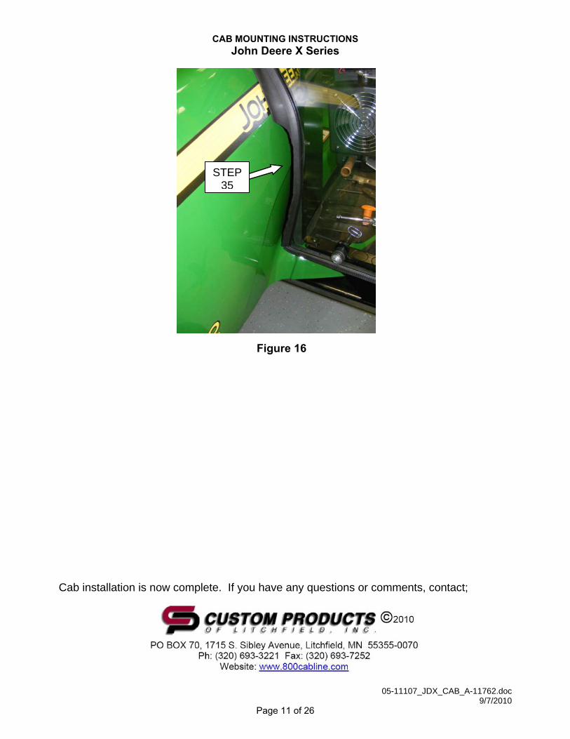
35) Make sure that the LH front intake area is free of obstructions to allow proper airflow. See figure 16.
Figure 14 (SHOWN WITH VINYL COVER REMOVED)
Figure 15 (SHOWN WITH VINYL COVER INSTALLED)
STEP 27
COWL
ITEM 8
ITEM 6
STEP 29 PEDAL NEEDS TO
OPERATE FREELY
Page 10 of 26
CAB MOUNTING INSTRUCTIONS John Deere X Series
05-11107_JDX_CAB_A-11762.doc 9/7/2010
Cab installation is now complete. If you have any questions or comments, contact;
Figure 16
STEP 35
Page 11 of 26


Page 13 of 26

Page 14 of 26

Page 15 of 26

Page 16 of 26


Page 19 of 26


Page 22 of 26


Page 25 of 26

Page 26 of 26