for macintosh and windowsindex-of.co.uk/tutorials-2/poser_4_-user_guide.pdfcontents ch0 welcome to...
TRANSCRIPT

User Guidefor Macintosh® and
Windows®

TrademarksProgram copyright 1991-99 Ghost Effects, Inc. All rights reserved. Interface copyright 1994-99 MetaCreations Corporation. All rights reserved. MetaCreations Poser is a trademark of MetaCreations Corporation. All other trademarks or registered trademarks are the property of their respective owners.
“Macintosh” is a registered trademark of Apple Computer, Incorporated. “Windows” is a registered trademark of Microsoft Corporation. “Pentium” is a registered trademark and “i486” is a trademark of Intel Corporation. ImageStream is a trademark and ImageStream Graphics Filters is a registered trademark of INSO Corporation. All other product names mentioned in the manual and other documentation are used for identification purposes only and may be trademarks or registered trademarks of their respective companies. Registered and unregistered trademarks used herein are the exclusive property of their respective owners. MetaCreations Corp. makes no claim to any such marks, nor willingly or knowingly misused or misapplied such marks.
CopyrightThis manual, as well as the software described in it is furnished under license and may only be used or copied in accordance with the terms of such license. Program ©1999 MetaCreations Corporation, including the look and feel of the product. MetaCreations Poser User Guide ©1999 MetaCreations Corporation. No part of this guide may be reproduced in any form or by any means without the prior written permission of MetaCreations Corporation.
NoticeBefore using this software or reading this user guide, make sure you have read, understood and agreed to the license contained in the back of the Poser User Guide.
CreditsPoser was originally created by Larry Weinberg. MetaCreations Poser was created by Larry Weinberg, Seath Ahrens, Jianhua Shen, Sree Kotay.
Original interface design by Phil Clevenger. New interface design by Kyle Maxwell.
Quality Assurance testing by Dan Huver, Lorna Brown, Brian Romero, Steve Yatson, and Jim Brown. Quality Assurance Management by Michael Cinque
Thanks to Technical Support lead Todd Burlingame.
Product management by Steve Cooper.
The User Guide was written by Carol Franger and Linda Stevens; Tutorial by Ian Grey and Erick Vera; edited by Laura Turnidge and Valarie Sanford; managed by Erick Vera; production by Landis Gwynn. Art direction by Brian Moose; cover illustration by Heather Dunnigan; manual and comic book illustrated by Nathan Harris; illustration assistance by Melinda Kniffen; layout design by Tish Loosley.
Collateral materials designed by Tish Loosley and Heather Dunnigan; production management by Rich O’Rielly.
Poser models by Zygote Media Group Inc. and Keith Hunter, Hunyes Publishing. Poser walk animations and gestures by Chris Derochie.
Special thanks to the Poser Web Community and the Poser Forum members for their contributions and support.

Contents
CH0 Welcome to Poser 4
What’s New in Poser 4? 12
Conforming Figures and Clothing 12
Bendable Props 12
New Lighting Features 12
Deformers 12
Morph Targets 12
Hierarchy Editor 12
Sketch Designer 13
Grouping Tool 13
Copying and Pasting 13
New Document Display Styles 13
When You Have Questions 13
About Your User Guide 14
Technical Support 14
Web Support 14
Phone Support 14
Installing Poser 15
System Requirements (Macintosh) 15
System Requirements (Windows) 15
Macintosh Installation 15
Windows Installation 16
CH1 Poser 4 Overview
How Poser Works 19
The Poser Workspace 20
The Document Window 20
Camera Controls 21
Light Controls 22
Document Display Style Controls 22
Editing Tools 23
The Libraries Palette 23
Animation Controls 24
The Menu Bar 24
CH2 Poser 4 Basics
Setting Up Poser 25
Macintosh Setup 25
Setting Application Preferences 26
Setting Up Your Workspace 27
UI Memory Dots 28
Workspace Backgrounds 28
Setting Up the Document Window 28
Placing Figures and Elements in the Studio 32
Using the Libraries Palette 32
Deleting Objects from a Scene 35
Working in the Document Window 36
Viewing Your Figure 36
Previewing Your Figure 37
Figure Properties 41
Element Properties 42
Using the Editing Tools 42
Selecting Body Parts 43
Pasting Figures onto the Background 43
Hiding Figures 44

Displaying Guides 44
Undoing Operations 46
Restoring Default Settings 46
Changing Defaults 46
Printing 47
Importing and Exporting 47
Saving and Closing 48
CH3 Tutorial
Welcome 51
The Basics 52
Lesson 1: Setting Up a Default Workspace 52
Lesson 2: Working with Cameras 55
Lesson 3: Tracking Modes 60
Lesson 4: Document Display Styles 60
Working with Lights 64
Lesson 1: Using the Light Control 64
Using Poser’s Tools 67
Lesson 1: The Parameter Dials 67
Lesson 2: The Rotate Tool 68
Lesson 3: The Twist Tool 70
Lesson 4: The Translate and Chain Break Tools 72
Posing 76
Lesson 1: Creating Poses 76
Lesson 2: Adding Poses to the Pose Library 81
Lesson 3: Posing Faces 82
Rendering 84
Advanced Tutorials 87
Character Creationand Animation 87
Lesson 1: Creating a Clown from Scratch 87
Lesson 2: Making the Clown Walk 91
Lesson 3: The Walk Designer 96
Lesson 4: Keyframe Editing 100
Lesson 5: Adding the Final Touch 105
Lesson 6: Setting Animated Cameras and Test Rendering 106
Lesson 7: Final Render 108
CH4 Posing
How Posing Works 109
Posing and Camera Views 110
Posing and the Library 110
Translation 110
Inverse Kinematics 111
Understanding IK 111
Turning IK On or Off 112
Limiting Motion 113
Posing Body Parts 113
Selecting Parts 113
Posing a Figure 113
Using the Editing Tools 114
Rotate Tool 115
Twist Tool 118
Translate/Pull Tool 119
Translate In/Out Tool 120
Chain Break Tool 120
Using the Parameter Dials 121
Default Parameter Dial Settings 122
Posing Parameters 122
Posing Parameters for the Body 123
C o n t e n t s

Symmetry 124
Drop to Floor 125
Copying and Pasting 125
Element Properties 126
Posing Hands 127
Using the Hand Model 128
Using Preset Hands 129
Posing Faces 129
Using the Parameter Dials 130
Posing Eyes 131
Faces and Phonemes 132
Using Preset Faces 133
Posing Animals 133
Posing Animal Heads 133
Pointing Body Parts 134
Locking Objects 134
Auto Balance and Posing 134
Saving Poses 135
Saving Poses in the Libraries Palette 135
Using the Pose Memory Dots 136
Using Poses from the Libraries Palette 136
CH5 Body Shaping
General Characteristics 138
Selecting Figures from the Library 138
Figure Height 139
Using the Color Tool 139
Shaping Individual Body Parts 140
Using the Shaping Tools 140
Using the Parameter Dials 141
Symmetry 141
Scaling the Body as a Whole 142
Using Parameter Dials 142
Copying and Pasting 143
Using the Deformer Tools 143
The Magnet Deformer 144
The Wave Deformer 149
Using Morph Targets 152
Using Morph Targets to Add Ethnicity 153
Using the Superhero Morph Target 154
Creating Custom Morph Targets 154
Using the Grouping Tool 157
Using the Group Edit Palette 158
Locking Figures and Body Parts 159
Saving Figures to the Libraries Palette 160
CH6 Props
How Props Work 161
Using Hair 163
Working with Clothing 164
Using Clothing without a Figure 166
Adding and Importing Props 166
Using Props from the Library 166
Importing Props 166
Deleting Props 168
Working with Props 168
Deforming Props 168
Creating Props 168
Creating New Prop Parameters 169
P o s e r 4

The Prop Origin 169
Prop Properties 170
Setting Prop Parents 171
Replacing a Body Part with a Prop 173
Adding Props to the Library 175
CH7 Cameras
How Cameras Work 177
The Main and Posing Cameras 179
The Auxiliary Camera 179
The Hand and Face Cameras 179
The Dolly Camera 179
The Orthogonal Cameras 179
Flyaround View 180
Selecting a Camera 180
The Camera Selection Control 180
Changing the Studio View 181
Positioning Cameras 181
Using Camera Parameter Dials 183
Focal Length 183
xOrbit 184
yOrbit 184
zOrbit 184
Yaw 184
Pitch 184
Roll 184
Scale 184
xScale 184
yScale 185
zScale 185
DollyX 185
DollyY 185
DollyZ 185
Camera Options 185
Pointing Cameras 186
Locking Camera Positions 186
Saving Camera Positions 186
Saving Camera Sets to the Library 186
Using the Camera Memory Dots 187
CH8 Lights
How Lights Work 189
Infinite Lights 190
Spotlights 191
Light Properties 191
Adding Lights 193
Aiming Lights 193
Using the Light Control 194
Using Light Indicators 195
Aiming with Parameter Dials 197
Pointing a Light at an Object 199
Lighting Color 199
Setting a Light’s Color 199
Setting Light Intensity 200
Setting Spotlight Characteristics 200
Using Shadows 201
Shadow Parameter Dials 202
Setting a Parent 202
Saving Light Sets 203
C o n t e n t s

CH9 Animating Figures
How Animation Works 206
Animation Tools 206
What You Can Animate 206
Animating Figures 206
Animating Hands 207
Animating Faces 207
Animating Props 208
Animating Deformers 208
Creating Animations 209
Setting Up Your Animation 210
Working with the Timeline 211
Recording Keyframes 212
Adding and Deleting Keyframes 213
Editing Animations 213
Editing Animation Setup 214
Viewing the Elements List 215
Editing Keyframes on the Timeline 217
Retime Keyframes 223
Advanced Editing 224
Keyframe Interpolation 224
Editing Keyframe Interpolation 225
Previewing Animations 228
Setting the Play Range 229
Using the Libraries Palette for Animations 229
Adding an Animation to the Library 230
Using a Multi-Frame Animation from the Library 230
CH10 Animation Techniques
Setting Keyframes 231
Creating Realistic Motion 232
Making Your Figure Walk 233
Creating a Walk Path 233
Designing a Walk 234
Editing a Walk 235
Saving a Walk 235
Loading a Walk 236
Applying a Walk 236
Animating Cameras 237
Turning Camera Animation On or Off 239
Animating Lights 239
Adding Sound 240
Editing Sound 240
Syncing Sound and Motion 240
Using Poser with OtherMotion Graphics Programs 241
Motion Capture and Animations 241
CH11 Surface Materials
How Surface Materials Work 243
Applying Surface Materials 244
Applying Materials to Body Parts 245
Applying Bump Maps 247
Creating a Custom Bump Map 247
Applying Texture Maps 249
Creating a Custom Texture Map 250
Applying Transparency Maps 252
Creating a Custom Transparency Map 252
P o s e r 4

Applying Reflection Maps 253
Reflective Color 254
Creating a Custom Reflection Map 254
Setting Colors 255
Object Color 255
Highlight Color 256
Ambient Color 257
CH12 Rendering
How Rendering Works 259
Setting Up a Render 260
Setting Render Destination 261
Setting Image Size 261
Choosing a Rendering Background 262
Setting Surface Detail 262
Rendering an Image 263
Using the Render Command 263
Antialias Rendering 263
Rendering an Animation 264
Using the Make Movie Dialog 264
Using the Sketch Designer 265
The Sketch Designer Window 266
Rendering a Sketch 269
CH13 Advanced Body Shaping
Creating Custom Morph Targets 272
Setting up Morph Targets 272
Morph Target Tutorial 273
Lesson 1: Setting Up 273
Lesson 2: Creating the
Morph Target 275
Lesson 3: Using the Target in Poser 277
Figure Joints and Blend Zones 278
Editing Joint Parameters 279
Using the Joint Parameters Palette 280
Interactively Editing Joint Parameters 280
Joint Attributes 282
Spherical Falloff Zones 287
CH14 Hierarchies
How Hierarchies Work 289
Using the Hierarchy Editor 290
Controlling what is Displayed 291
Collapsing the Hierarchy Editor 291
Selecting Objects 292
Deleting Objects 292
Renaming Objects 293
Reordering Objects 293
Displaying Object Properties 294
Changing Object Visibility 294
Establishing Hierarchical Relationships 295
Creating Multi-Figure Hierarchies 298
Applying the Standard Hierarchy 299
Applying Standard Rotation Order 299
Setting Inverse Kinematics 299
C o n t e n t s

CH15 Creating Custom Figures
Modifying Existing Figures 302
Combining Multiple Figures 303
Combining Props 303
Creating Figures using other Software 304
Deciding how to Start 304
Understanding the Process 305
Determining Model Format 305
Grouping Body Parts 305
Naming Groups 306
Arranging Groups on a Model 307
Looking inside the Poser Hierarchy File 308
Converting Hierarchy Files 312
Verifying Hierarchy Files 312
Adjusting Joint Parameters 312
Setting Limits 313
Setting Favored IK Angles 313
Memorizing Default Positions 314
Setting Surface Materials 314
Adding Morph Targets 314
Naming Body Parts 314
Tutorial: Creating a Figure in Ray Dream Studio 315
CH16 Using Poser 4 with OtherApplications
Using Poser with Ray Dream Studio 5 323
Using Poser with Painter 3D 326
Using Poser with Bryce 3D 328
Using Poser on the World Wide Web 331
Internet Connection 331
Using a Browser 331
Accessing the Web 332
Using Poser with MetaStream 333
Using Poser with Canoma 333
AppA Troubleshooting
AppB Glossary
P o s e r 4

C o n t e n t s


Welcome to Poser 4
Poser is an easy-to-use figure design and animation tool. With Poser you’ll produce lifelike 3D illustrations and animations of human and animal figures in action—dancing, scaling a cliff, meditating, even walking.
Poser is great for anyone who wants to add realistic human and animal figures to an art project. It’s a welcome companion to your favorite graphics, illustration, 3D, animation, and multimedia applications.

What’s New in Poser 4?If you’re a Poser 3 user, the following information will bring you up to date with the new features in Poser 4.
Conforming Figures and Clothing
One of the most requested features for Poser is the ability to change clothes on the Poser figures. Poser now includes wardrobes of custom clothing in the Libraries palette. Custom clothing behaves the same as Poser figures; each article includes parameters for the corresponding body parts. You can conform clothing to a figure so that it moves as the figure moves. Refer to “Working with Clothing” on page 164 for complete information on clothing.
Bendable Props
When you attach a prop to a body part, you can configure it to bend as the body part bends. This feature is helpful for naturally bendable objects, such as a rollerblader’s elbow pads. For details, refer to “Setting Prop Parents” on page 171.
New Lighting Features
Poser’s lighting controls are completely redesigned. Now you have the choice of using traditional infinite lighting or spotlights that you can move around the studio. You can add an unlimited number of lights, as well as
delete them, to fit your needs. The new light control also includes an intensity control. All the new lighting features are discussed in “Lights” on page 189.
Poser now supports spherical reflection maps and transparency maps. For details, refer to “Surface Materials” on page 243.
Deformers
Poser now includes two deforming tools. The Magnet deformer allows you to stretch and pull body parts and props. The Wave deformer lets you add ripples to objects such as clothing, ground planes, and props. Deformers can be animated and used to create morph targets. These tools are discussed in detail in “Using the Deformer Tools” on page 143.
Morph Targets
You can now access a library of figures and props with built-in morph targets. Poser includes targets for single body parts as well as a full figure morph. You can also use the deformers and Parameter Dials to create your own morph targets. The possible applications for morph targets are infinite. Learn all about morph targets in “Using Morph Targets” on page 152.
Hierarchy Editor
With Poser’s new Hierarchy Editor, you now have complete control over the figures, props, cameras, and lights in your scene. The Hierarchy Editor provides an easy way to select, delete, and rename objects. It’s never been easier to turn visibility on or off for figures, body parts, props, or lights. With the
We l c o m e t o P o s e r 4

Hierarchy Editor, you can adjust parent-child relationships and create IK chains. For the truly ambitious, the Hierarchy Editor is an exciting route to creating brand new Poser figures. Refer to “Hierarchies” on page 289 for complete information.
Sketch Designer
Rendering possibilities are greatly expanded with the new Sketch Designer, which lets you create and refine hand-drawn quality portraits of your scenes. Drawings are rendered with a series of brush strokes that define the background, edges, and actual elements. Many drawing options are available, so you can tailor the strokes to your liking. For details, refer to “Using the Sketch Designer” on page 265.
Grouping Tool
The new grouping tool is a powerful feature for assigning materials and generating new props and objects. It also complements the deformer tools and morph targets: you can specify sections of a body part or prop for deforming and morphing. Refer to “Using the Grouping Tool” on page 157 for complete information.
Copying and Pasting
Cut, Copy, and Paste commands are now included in the Edit menu, so you can easily copy poses, body shaping, and animations to other figures, body parts, and props. This new functionality is explained in detail in “Copying and Pasting” on page 143.
New Document Display Styles
You can choose from 12 interactive display styles in the Document Display Style palette. New styles include flat shaded with mesh, smooth shaded with mesh, and cartoon style without lines. Refer to “Previewing Your Figure” on page 37 for explanations of all 12 display styles.
When You Have QuestionsYou can find answers to most of your questions in the following sources:
• Status line tips - As you move the cursor over most UI elements, descriptions appear at the top of their palette or window.
• Poser 4 User Guide - Provides all the information you need to get the most out of Poser. The Poser CD includes a PDF version of the User Guide. Adobe Acrobat Reader is required to read the PDF file format. Adobe Acrobat Reader software is available on the Poser CD or downloadable for free from www.adobe.com.
• Web links - You can launch your web browser and access MetaCreations and Poser-related web sites directly from Poser. To do this, choose Help menu> Web Links> choose a link.
P o s e r 4

About Your User GuideThe Poser 4 User Guide is for both Macintosh and Windows. By convention, Macintosh commands precede Windows commands in the text. For example, Command/Ctrl+I, is equivalent to the Macintosh Command-I and the Windows Ctrl+I. For simplicity, the term “folder” refers to directories as well as folders. The Poser interface for Macintosh and Windows platforms is identical, unless otherwise specified.
When a modifier key differs between the Macintosh and Windows platform, the Macintosh modifier is listed first followed by a slash and the Windows modifier key. Option/Alt means Macintosh users press the Option key and Windows users press Alt.
There are several conventions used to identify paths to certain tools and controls. The convention to a menu follows the rule of the menu name> menu item. The convention to a palette follows the rule of the palette name: subpalette name. The convention to a palette menu follows the rule of palette name: palette menu> menu item.
Technical SupportOnline technical support is free to registered users of Poser. There are two easy ways to contact technical support for questions about installation, configuration, or functionality. These options are: Web support and phone support.
You’ll find the answers to most of your questions in this User Guide. If you need further assistance, you can contact MetaCreations’ Technical Support in the following ways:
Web SupportMany of the answers to your questions are available 24 hours a day on our Web site:
http://www.metacreations.com/support
In addition to frequently asked questions (FAQs), the Web site provides troubleshooting techniques, late breaking product news, and other resources to help you get the most out of Poser.
Phone SupportFree phone support is available for a limited duration after your first call. The length of time varies based on the product and whether it is an upgrade or a first-time purchase. MetaCreations also provides additional paid support options. Details about phone support can be found in the Technical Support insert included with your product.
Phone support hours are Monday–Friday, 8:00 AM–5:00 PM Pacific Standard Time, excluding holidays.
For Standard Support, call (831) 430-4000. Please have your serial number handy and be at the computer where you need assistance.
For international support, please contact your local distributor. To locate the distributor nearest to you, check the Web site at:
http://www.metacreations.com/support/intl
We l c o m e t o P o s e r 4
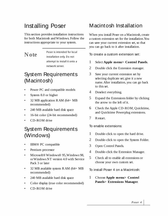
Installing PoserThis section provides installation instructions for both Macintosh and Windows. Follow the instructions appropriate to your system.
System Requirements (Macintosh)
• Power PC and compatible models
• System 8.0 or higher
• 32 MB application RAM (64+ MB recommended)
• 240 MB available hard disk space
• 16-bit color (24-bit recommended)
• CD-ROM drive
System Requirements (Windows)
• IBM® PC compatible
• Pentium processor
• Microsoft® Windows® 95, Windows 98, or Windows NT version 4.0 with Service Pack 3 or later
• 32 MB available system RAM (64+ MB recommended)
• 240 MB available hard disk space
• Color display (true color recommended)
• CD-ROM drive
Macintosh Installation
When you install Poser on a Macintosh, create a custom extension set for the installation. You can save your current extension set, so that you can go back to it after installation.
To create a custom extension set:
1 Select Apple menu> Control Panels.
2 Double click the Extension manager.
3 Save your current extension set by selecting duplicate set; give it a new name. After installation, you can go back to this set.
4 Deselect everything.
5 Expand the Extensions folder by clicking the arrow to the left of it.
6 Check the Apple CD-ROM, Quicktime, and Quicktime Powerplug extensions.
7 Restart.
To enable extensions:
1 Double-click to open the hard drive.
2 Double-click to open the System Folder.
3 Open Control Panels.
4 Double-click the Extension Manager.
5 Check all to enable all extensions or choose your own custom set.
To install Poser 4 on a Macintosh:
1 Choose Apple menu> Control Panels> Extensions Manager.
NotePoser is intended for local
installation only. Do not
attempt to install it onto a
network server.
P o s e r 4

2 To save your current extensions setting, click Duplicate Set, and enter a name in the dialog that appears. This will be the set of extensions you use for the installation.
3 In the new set, expand the Extensions folders and deselect all extensions except those for:
• CD-ROM or DVD-ROM
• Quicktime
• Quicktime Powerplug
4 Insert the Poser 4 CD-ROM into your computer’s CD-ROM drive. The Install Poser dialog appears.
5 Double-click the Poser icon.
6 Follow the instructions provided by the installer.
The installation dialog displays an important ReadMe.
7 Click Accept after reading the complete ReadMe.
Windows Installation
Before you install on Windows, you must end any background tasks except for Systray and Explorer.
To end background tasks in Windows:
1 Type Ctrl-Alt-Delete. The Close Program dialog appears.
2 Click End Task for all items except Systray and Explorer.
This must be done one item at a time; repeat these steps to end each task that is open.
To install Poser 4 on Windows:
1 Insert the Poser 4 CD-ROM into your computer’s CD-ROM drive. The Install Poser dialog appears.
2 Double-click the Poser icon.
3 Follow the instructions provided by the installer.
The installation dialog displays an important ReadMe.
NoteIf you are not using standard
Apple drives, your drives may
require additional extensions
to run properly. If so, turn
those extensions on.
TipIncrease the RAM available to
Poser by allocating any unused
RAM to it. This allows Poser to
run faster and handle larger
files and renderings. However,
be sure to leave some RAM for
the system software. System
software must dynamically
allocate RAM to itself when
required.
We l c o m e t o P o s e r 4

4 Click Yes after reading the complete ReadMe.
Poser installs into C:/Programs/MetaCreations/Poser. If you change the drive where you want to install Poser, be sure to include a folder. For example, if you install on the D: drive, your path could be D:/Poser.
P o s e r 4

We l c o m e t o P o s e r 4

1Poser 4 Overview
How Poser WorksPoser is the easiest and most effective tool you can use to pose and animate figures. It is the perfect complement to any 3D illustration or character animation tool.
With Poser you can:
• Choose a figure from a large number of pre-built models included in the Poser Libraries
• Pose the figure using the posing tools
• Add colors and textures to your figures to create realistic or fantastic looks
• Set up poses to use as keyframes for an animation
• Render figures as still images or animations
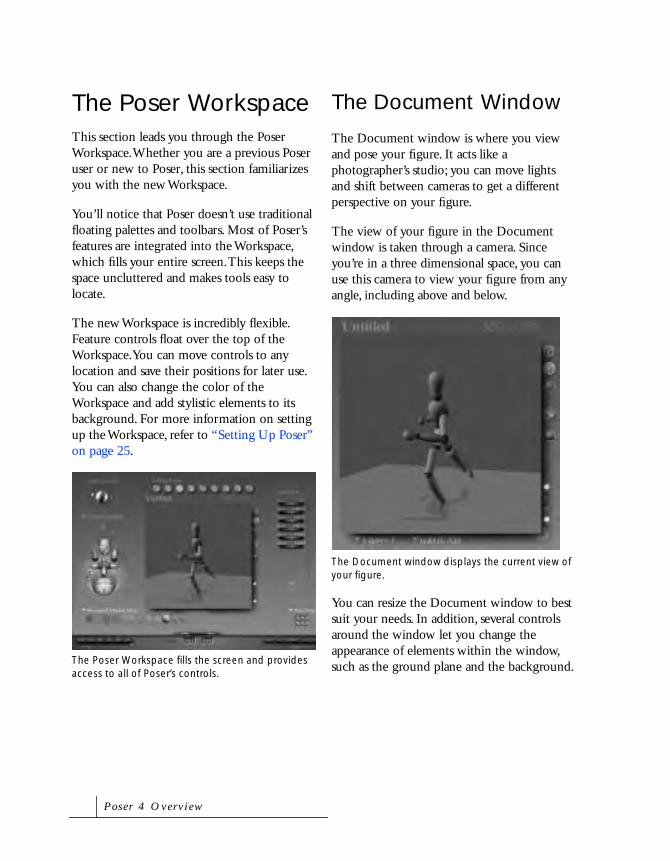
The Poser WorkspaceThis section leads you through the Poser Workspace. Whether you are a previous Poser user or new to Poser, this section familiarizes you with the new Workspace.
You’ll notice that Poser doesn’t use traditional floating palettes and toolbars. Most of Poser’s features are integrated into the Workspace, which fills your entire screen. This keeps the space uncluttered and makes tools easy to locate.
The new Workspace is incredibly flexible. Feature controls float over the top of the Workspace. You can move controls to any location and save their positions for later use. You can also change the color of the Workspace and add stylistic elements to its background. For more information on setting up the Workspace, refer to “Setting Up Poser” on page 25.
The Document Window
The Document window is where you view and pose your figure. It acts like a photographer’s studio; you can move lights and shift between cameras to get a different perspective on your figure.
The view of your figure in the Document window is taken through a camera. Since you’re in a three dimensional space, you can use this camera to view your figure from any angle, including above and below.
You can resize the Document window to best suit your needs. In addition, several controls around the window let you change the appearance of elements within the window, such as the ground plane and the background.The Poser Workspace fills the screen and provides
access to all of Poser’s controls.
The Document window displays the current view of your figure.
P o s e r 4 O v e r v i e w

The Ground Plane
The Ground plane represents the floor of the posing studio. This plane helps you orient the figure in 3D space. It also helps you orient your view of the figure. As you move the camera, the ground plane tilts or rotates to indicate the new orientation.
Camera Controls
The Camera Controls set the view of your figure in the Document window. There are two types of Camera Controls: the View controls and the Positioning controls.
The View controls let you move between a number of preset views. By clicking or dragging this control, you can access all the available views in Poser.
The Positioning controls let you move the camera interactively. There are two sets of positioning controls: the Camera Plane controls and the Rotation Trackball. The
Use the Ground Plane to orient your figure in 3D space.
Use the Camera Controls to set the view of your scene.
The View controls let you quickly move the camera to a preset position.
P o s e r 4

Camera Plane controls let you move the camera along specific planes. For example, you can move the camera in only a vertical or horizontal direction.
Tool titles indicate which two axes the camera is moving in.
The Rotation Trackball control lets you tilt and spin a camera around the studio. With this control you can move the camera to almost any position while still keeping the figure in the center of your field of view.
Light Controls
The Light Controls let you define preset positions for the lights in your virtual studio. With these controls you can change light color or illuminate your figure from various angles.
Document Display Style Controls
The Document Display Style controls let you set the preview quality of the figure in the Document window.
There are several preview styles available. Different styles work best for different operations. For example, at times you may want to view the entire mesh of a figure (Wireframe), at other times you may prefer a realistic look (Smooth Shaded).
The Camera Plane controls let you move the camera along a plane in 3D space.
The Rotation Trackball lets you move a camera around the Document window.
NoteThe Rotation trackball does not
affect the orthogonal cameras.
Use the Light Controls to set up the lighting for your figure.
The Document Display Style controls let you set how your figure is displayed in the Document window.
P o s e r 4 O v e r v i e w

Editing Tools
The Editing Tools let you adjust the position of the figure’s body parts to create specific poses. Each tool moves the figure in a different way. Using a combination of controls, you can create an infinite number of poses.
The Parameter Dials
The Parameter Dials let you pose figures more precisely than the Editing Tools by adjusting the values of specific parameters.
If all the Parameter Dials do not fit in the window, use the scroll bar to slide through the list.
The Libraries Palette
The Libraries palette contains all the figures and props available in Poser, as well as custom poses and light and camera settings. From this palette, you can access sub-categories and preview each figure or prop.
Use the Libraries palette to add or replace figures or props in the Document window.
The Editing Tools let you set the position of your figure’s body parts.
The Parameter Dials let you precisely pose your figure using numerical values.
The Libraries palette contains all the figures and props available in Poser.
P o s e r 4

Animation Controls
The Animation controls let you quickly set up animation keyframes. You can set up a pose as a keyframe, change to a new keyframe, change the pose, then set another keyframe. When you play the animation, the figure appears to move from one pose to the other.
With the Animation controls, you can move quickly through keyframes, and add or delete them as needed.
Animation Palette
The Animation palette displays the animation timeline and lists all the keyframes that you have created for the figure. Use the palette to fine tune an animation.
The Menu Bar
Although the Poser Workspace fills the entire screen, you can still access several features through the Menu Bar. You can also switch between Poser and other applications. On the Macintosh, the Menu Bar appears when you move the cursor over the top of the Workspace.
The Animation controls let you quickly set up keyframes for your animation.
The Animation palette lets you refine and edit your animations.
P o s e r 4 O v e r v i e w

2Poser 4 Basics
This chapter describes how to set up Poser 4 and describes some basic techniques for posing figures.
Setting Up PoserPoser is a color application. For the best preview display, set your display to the highest color depth possible. To do this, use the Macintosh Monitors control panel, the Windows Setup options, or your video adapter control panel.
Macintosh Setup
By default, the Macintosh version of Poser is allocated a specific amount RAM appropriate for most systems. If you have more memory available, increase Poser’s memory allocation to improve

application performance. To check the application’s memory allocation, choose the Apple Menu> About this Macintosh in the Finder.
To increase Poser’s memory allocation:
1 Make sure Poser is not running.
2 From the Finder, click the Poser program icon.
3 Choose File menu> Get Info. The Poser Information dialog appears.
4 For System 8.5 or higher, choose Memory from the Show popup
5 In the Memory Requirements section, increase the Preferred Size to a level appropriate for your system.
For Poser to operate well with fully articulated Poser people figures, it must have at least 32 MB of RAM. However, do not use all the available memory on your computer; leave one megabyte or more for the system.
If you don’t have enough RAM, you can turn on virtual memory, which uses some disk space with a cost of slower performance.
Setting Application Preferences
Poser’s preferences dialog lets you control how the application appears when it opens.
To set application preferences:
• Choose Edit menu> General Preferences. The General Preferences dialog appears.
Document Preference
The Document Preference controls how the document appears when you start Poser or create a new document. You can make the document appear as it did when you last closed it, or in its default state.
For example, if you want to always start Poser with the Casual Woman and the ground plane on, you can load the woman, turn on the Ground Plane, and set this as the preferred state.
To set the Preferred State:
1 In the Poser workspace, move the palettes and controls to the positions you prefer.
Use the Get Info dialog to allocate memory to Poser on the Macintosh
Use the General Preferences dialog to set the interface’s appearance and the application’s launch state.
P o s e r 4 B a s i c s

2 Choose Edit menu> General Preferences. The General Preference dialog appears.
3 Click the Set Preferred State button.
To set the Factory state:
1 Enable the Launch to Factory State button.
2 Click OK
Interface Preference
The Interface Preference controls how the interface appears when you open Poser without using an existing document.
To set interface preferences:
• If you want the application to appear as it did when you closed it, enable the Use to Previous State radio button.
• If you want the application to launch in its default state, enable the Use to Factory State radio button
To close the General Preferences dialog, click OK.
Setting Up Your WorkspaceYour Workspace reflects the layout of the controls and Document window. You can customize most controls within the Workspace can be customized to suit the way you work; place controls anywhere in the Workspace and store those changes for later use.
To re-position an element in the Workspace:
• Click the element’s title and drag it to a new position.
You can drag any of the controls, such as the Camera, Light, Display Style, and Parameter Dial controls.
To re-position the Document window:
• Click the text label above the Document window and drag it to a new location.
To “window shade” a control so only its title appears:
• Double-click the title bar.
NoteAs you move the cursor over the
controls, text describing the
Workspace elements appear
P o s e r 4

UI Memory Dots
The nine UI dots in the bottom-right corner of the Workspace store Workspace layouts, Poses, and Camera positions.
To save a Workspace layout:
1 Click the arrow icon next to the memory dot element title and choose UI Dots from the menu that appears.
2 Arrange the Workspace controls to their optimal positions.
3 Click an empty UI Dot. The Workspace layout is stored in that memory dot.
To retrieve a Workspace layout:
1 Make sure the memory Dot element title is selected.
2 Click on a full memory dot. The interface elements are re-arranged to conform to the stored layout.
To delete a saved Workspace layout:
• Option/Alt-click a full memory dot. The layout information is deleted from the memory dot.
Workspace Backgrounds
The Poser Workspace background includes several stylistic elements. You can change, move, or hide the figure, and you can change the Workspace background color.
To change the Workspace background figure:
• Option/Alt-click the background figure. Continue clicking until an image you like appears (one option is no figure).
To reposition the background image:
• Drag the figure to a new position.
To change the Workspace background color:
1 Click the Color tool.
2 Click on the background and choose a color from the Color picker.
To restore the default Workspace background color:
• Option/Alt-click the background.
Setting Up the Document Window
The Document window provides a view of the studio where you pose and view your figure. There are several parameters that allow you to change the window appearance to suit the way you work.
Use the Memory dots to save Workspace layouts, Poses, and Camera positions.
NoteYou cannot use Poser 3 UI
preferences in Poser 4
Full Memory Dot
Empty Memory Dot
P o s e r 4 B a s i c s

To interactively set the Document window size:
• Drag the size control circle until the window is the desired size.
To numerically set the Document window size:
1 Double-click the window dimensions at the top-right corner of the Document window, or choose Window menu> Document Window Size. The Set Window Size dialog appears.
2 Enter Width and Height values.
3 Click OK.
To move the Document window:
• Drag the Document window’s title to a new position.
Document Window Color
To improve your view of the figure, you can set the background, foreground, shadow, and ground colors of the document window.
The Color controls are located in the bottom-right corner of the window.
To set the Document window colors:
1 Click the appropriate color button on the bottom-right corner of the Document window.
2 Drag the dropper icon over the color picker that appears. Release the mouse button when you select the desired color.
Drag the size control to resize the Document window.
Use the Color controls to set the color of Document window elements.
TipTo access the standard Macintosh
or Windows color picker,
Command/Ctrl-click the color
button.
Foreground Color
Background Color
Shadow Color
Ground Color
P o s e r 4

Depth Cueing
Depth Cueing adds dimension to objects in the Document window. Elements that are farther away fade into the distance.
To enable or disable Depth Cueing:
• Click the Depth Cueing button on the bottom-left corner of the Document window.
Figure Tracking
Tracking is a performance enhancing feature that changes the display of an object as you reposition its parts. For example, if you use Fast Tracking, a figure’s body parts display as boxes when you’re moving them, then revert to their display style when they stop moving,
You can use the following types of tracking in the Document window:
• Box Tracking displays figures and objects as boxes at all times. Box Tracking is the fastest way to render objects.
• Fast Tracking displays figures and objects as boxes only when they are being dragged or animating.
• Full Tracking uses the display style at all times. With Full Tracking, large or complex objects render more slowly.
An example of Depth Cueing with a figure in Wireframe display style.
The Depth Cueing button.
Enabled Disabled
An example of Fast Tracking using a figure in Flat Shaded display style.
P o s e r 4 B a s i c s

To enable a tracking mode:
• Click one of the tracking option buttons on the top-right corner of the Document window.
Paper Textures
You can enhance the view of the Document window by changing the Paper Texture. There are several texture options available—such as Paper, Weave, and Grid—to help you precisely position your figure.
To choose a paper texture:
• Choose Display menu> Paper Texture> desired texture.
To clear a paper texture:
• Choose Display menu> Paper Texture> None.
Drop Shadows
Figures in the studio cast drop shadows directly on the ground plane. Shadows can help you orient a figure in 3D space. You can turn shadows off to save on redraw time.
To turn drop shadows on or off:
• Click the Display Shadows button on the right side of the Document window.
The Figure Tracking option buttons.
A figure with a grid line texture applied to the background.
Full Tracking
Fast Tracking
Box Tracking
The Display Shadows option button.
NoteDrop shadows are not actually
shadows cast by a light; they
always appear directly beneath
an object on the ground floor.
Shadows cast by lights appear
only when a scene is rendered.
Refer to “Rendering” on
page 259 for details.
On Off
P o s e r 4

Placing Figures and Elements in the StudioThe main working area of the Poser Workspace is the studio in the Document window. The figure that appears in the studio is determined by the model you load from the Figures category of the Libraries palette, or from a document or import. The Libraries palette is the main tool you’ll use to load figures and props.
Using the Libraries Palette
The Libraries palette provides access to all the preset figures, props, light sets, and camera sets available in Poser. The content of the libraries palette is divided into eight categories.
Each category includes sub-categories. For example, the Figures category includes the subcategories People, Animals, Poser2 figures, etc. Each sub-category contains figures to choose from.
Once you load a figure into your studio from the library, you can customize it and save it back to the library for future use.
To display the Libraries palette:
• Click the handle on the right side of the screen.
or
Choose Windows menu> Libraries.
NoteSome figures are more posable
than others. The People sub-
category of the Figures category
give you more control over hands
and faces. Poser 2 figures have
less control.
The Libraries palette divides the available content into categories. Each category palette provides previews.
Sub-category popup
Categories
Previews
P o s e r 4 B a s i c s
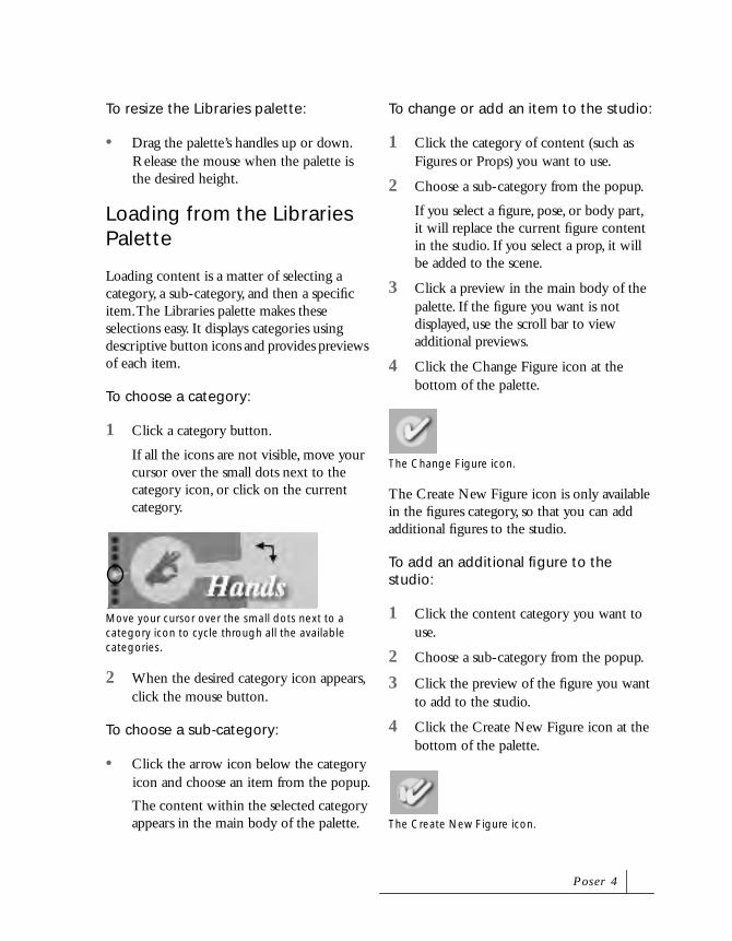
To resize the Libraries palette:
• Drag the palette’s handles up or down. Release the mouse when the palette is the desired height.
Loading from the Libraries Palette
Loading content is a matter of selecting a category, a sub-category, and then a specific item. The Libraries palette makes these selections easy. It displays categories using descriptive button icons and provides previews of each item.
To choose a category:
1 Click a category button.
If all the icons are not visible, move your cursor over the small dots next to the category icon, or click on the current category.
2 When the desired category icon appears, click the mouse button.
To choose a sub-category:
• Click the arrow icon below the category icon and choose an item from the popup.
The content within the selected category appears in the main body of the palette.
To change or add an item to the studio:
1 Click the category of content (such as Figures or Props) you want to use.
2 Choose a sub-category from the popup.
If you select a figure, pose, or body part, it will replace the current figure content in the studio. If you select a prop, it will be added to the scene.
3 Click a preview in the main body of the palette. If the figure you want is not displayed, use the scroll bar to view additional previews.
4 Click the Change Figure icon at the bottom of the palette.
The Create New Figure icon is only available in the figures category, so that you can add additional figures to the studio.
To add an additional figure to the studio:
1 Click the content category you want to use.
2 Choose a sub-category from the popup.
3 Click the preview of the figure you want to add to the studio.
4 Click the Create New Figure icon at the bottom of the palette.
Move your cursor over the small dots next to a category icon to cycle through all the available categories.
The Change Figure icon.
The Create New Figure icon.
P o s e r 4

Saving to the Libraries Palette
In the Libraries palette, you can create your own set of customized figures and poses, which you can easily retrieved and use in other illustrations. You can save custom camera and light configurations, poses, and figures to the library.
When you save an item to the Libraries palette, you create a new set within the currently selected sub-category.
You can either save an item to an existing sub-category, or create a new sub-category for your item.
To create a new sub-category:
1 Click the category of content where you want to add a new sub-category.
2 Click the sub-category popup and choose Add category. The New Library dialog appears.
3 Enter a name for your new sub-category and click OK.
Your new sub-category appears at the end of the menu.
To save an item to a library:
1 Click the content category you want to save to. For example, if you want to save a pose, click the Poses category.
2 Choose a sub-category from the popup.
3 Click the Add to Library (+) icon at the bottom of the palette. A dialog appears.
4 For the Poses, Faces, Props, Lights, and Cameras categories, you can specify parts of the scene to include or not include. To do this, click the Select Subset button. In the Hierarchy Selection list that appears, deselect any items in the scene that you don’t want to include, then click OK.
5 Enter a name for your library item and click OK.
The Hierarchy Selection list.
P o s e r 4 B a s i c s

6 A dialog appears asking if you want to save a Single frame or a multi-frame animation.
• If you select the Single frame option, the current pose is saved, or if you have an animation set up, only the current frame is saved.
• If you select the Multi-frame animation option, you can specify a range of frames to save.
Select either Single frame or Multi-frame animation and click OK.
The item is added to the selected category.
To delete an item from the library:
1 Select the preview of the item you want to delete.
2 Click the Delete from Library (-) icon at the bottom of the palette.
Deleting Objects from a Scene
At some point you may wish to delete one or more of the figures and props you have added to the studio.
To delete a figure or prop from the studio:
1 Select the figure or prop you want to delete from the Current Figure or Current Element popup.
2 Press Delete.
You can also delete items using the Hierarchy Editor. For details, refer to “Deleting Objects” on page 292.
You can save a still or the entire animation.
NoteThis command permanently
deletes items from the library;
make sure you really want to
delete the item before accepting
the message in the warning
dialog.
NoteYou cannot undo this delete
command.
P o s e r 4

Working in the Document Window
Viewing Your Figure
The camera position determines your view in the Document window. The Camera Controls let you quickly move the camera to different positions as you pose your figure.
You can move the camera in any direction within the studio. However, positioning it can be an involved process. This section outlines how to quickly move the camera to the most commonly used positions. For more detailed instruction on positioning the cameras, refer to “Changing the Studio View” on page 181.
The available cameras are: Main, Auxiliary, Left, Right, Top, Bottom, Front, Back, Right Hand, Left Hand, Face, Posing, Dolly, and Flyaround View.
To select a camera view:
• Drag the cursor over the Select Camera control, until the desired Camera view appears.
or
Click the Select Camera popup and choose the desired view.
To switch to the face camera:
• Click the Face Cam icon at the top of the Camera controls.
or
Click the Select Camera popup and choose Face Camera.
To switch to a hand camera:
• Click either the Left or Right Hand Camera icons.
or
Click the Select Camera popup and choose either Right Hand or Left Hand Camera.
To view the entire figure:
• Click the Select Camera popup and choose Main Camera or Posing Camera.
Use the Camera Controls to change the view of your figure.
P o s e r 4 B a s i c s
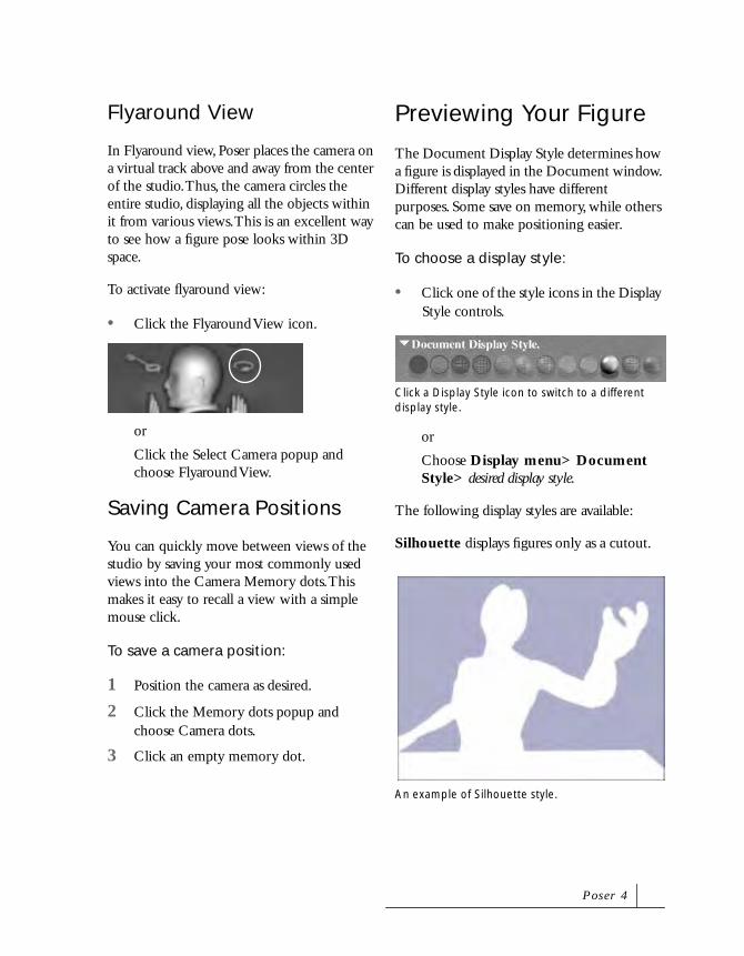
Flyaround View
In Flyaround view, Poser places the camera on a virtual track above and away from the center of the studio. Thus, the camera circles the entire studio, displaying all the objects within it from various views. This is an excellent way to see how a figure pose looks within 3D space.
To activate flyaround view:
• Click the Flyaround View icon.
or
Click the Select Camera popup and choose Flyaround View.
Saving Camera Positions
You can quickly move between views of the studio by saving your most commonly used views into the Camera Memory dots. This makes it easy to recall a view with a simple mouse click.
To save a camera position:
1 Position the camera as desired.
2 Click the Memory dots popup and choose Camera dots.
3 Click an empty memory dot.
Previewing Your Figure
The Document Display Style determines how a figure is displayed in the Document window. Different display styles have different purposes. Some save on memory, while others can be used to make positioning easier.
To choose a display style:
• Click one of the style icons in the Display Style controls.
or
Choose Display menu> Document Style> desired display style.
The following display styles are available:
Silhouette displays figures only as a cutout.
Click a Display Style icon to switch to a different display style.
An example of Silhouette style.
P o s e r 4

Outline displays only the outline of the figure.
Wireframe displays figures and objects as a mesh.
Hidden Line displays figures and objects as a mesh, but portions of the mesh not is the cameras field of view do not display.
Lit Wireframe displays figures and objects as a colored mesh, where the color of a section of mesh corresponds to the color of the surface material.
An example of Outline style.
An example of Wireframe style.
An example of Hidden Line style.
An example of Lit Wireframe style.
P o s e r 4 B a s i c s
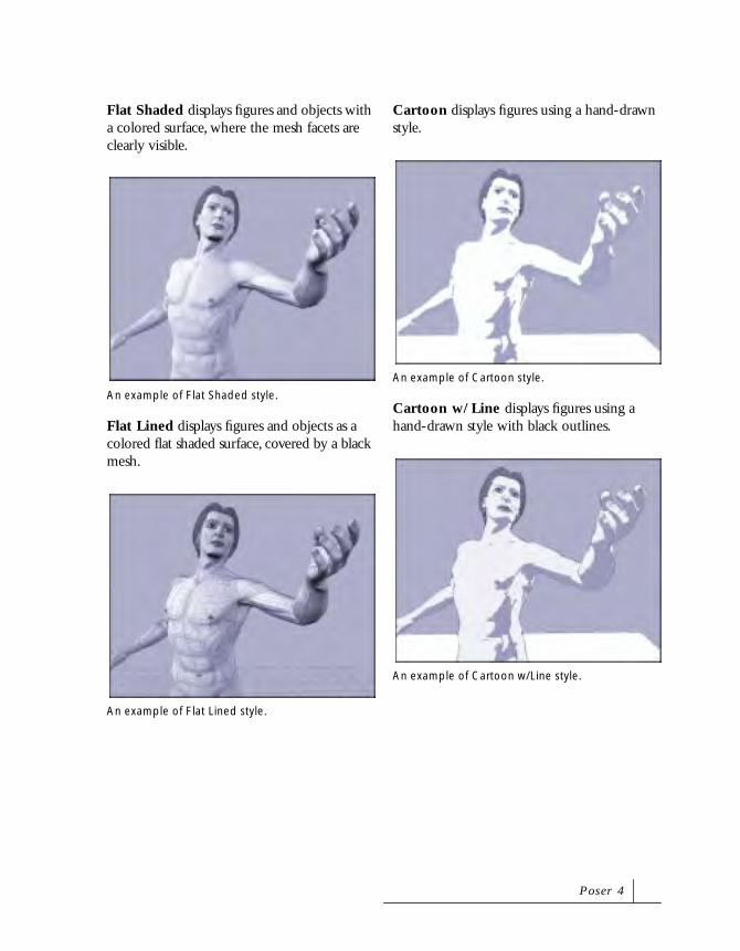
Flat Shaded displays figures and objects with a colored surface, where the mesh facets are clearly visible.
Flat Lined displays figures and objects as a colored flat shaded surface, covered by a black mesh.
Cartoon displays figures using a hand-drawn style.
Cartoon w/Line displays figures using a hand-drawn style with black outlines.
An example of Flat Shaded style.
An example of Flat Lined style.
An example of Cartoon style.
An example of Cartoon w/Line style.
P o s e r 4

Smooth Shaded displays figures and objects as a smooth continuous surface.
Smooth Lined displays figures and objects as a smooth shaded surface, covered by black mesh lines.
Texture Shaded displays figures and objects using texture mapping.
All styles except Silhouette, Outline, Wireframe, and Hidden Line are affected by lighting changes.
You can apply a Display Style to a figure, the entire document, or a specific body part. Different styles can save on redraw time and help you isolate specific body parts while you’re working. Cartoon w/Line, Flat Lined, and Smooth Lined styles are slower than their non-lined counterparts.
To apply a display style to the entire document:
• Click the popup next to the Display Style icons and choose Document Styles.
To apply a display style to the entire figure:
• Click the popup next to the Display Style icons and choose Figure Styles.
An example of Smooth Shaded style.
An example of Smooth Lined style.
An example of Texture Shaded style.
P o s e r 4 B a s i c s
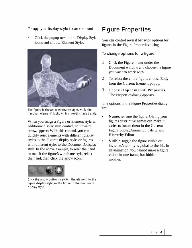
To apply a display style to an element:
• Click the popup next to the Display Style icons and choose Element Styles.
When you assign a Figure or Element style, an additional display style control, an upward arrow, appears. With this control, you can quickly reset elements with different display styles to the Figure’s display style, or figures with different styles to the Document’s display style. In the above example, to reset the hand to match the figure’s wireframe style, select the hand, then click the arrow icon.
Figure Properties
You can control several behavior options for figures in the Figure Properties dialog.
To change options for a figure:
1 Click the Figure menu under the Document window and choose the figure you want to work with.
2 To select the entire figure, choose Body from the Current Element popup.
3 Choose Object menu> Properties. The Properties dialog appears.
The options in the Figure Properties dialog are:
• Name: rename the figure. Giving your figures descriptive names can make it easier to locate them in the Current Figure popup, Animation palette, and Hierarchy Editor.
• Visible: toggle the figure visible or invisible. Visibility is global to the file. In an animation, you cannot make a figure visible in one frame, but hidden in another.
The figure is shown in wireframe style, while the hand (an element) is shown in smooth shaded style.
Click the arrow button to switch the element to the figure display style, or the figure to the document display style.
P o s e r 4

Element Properties
You can control several behavior options for body parts in the Element Properties dialog. You can rename parts, make them invisible, and control whether they cast shadows or not.
To change options for a body part:
1 Click the Figure menu under the Document window and choose the figure you want to work with.
2 Choose a specific body part from the Current Element popup.
3 Choose Object menu> Properties. The Properties dialog appears.
4 Set any of the following options in the Element Properties dialog:
• Name: rename the part.
• Visible: toggle the part visible or invisible. In an animation, you cannot make an element visible in one frame, but hidden in another.
• Casts Shadow: toggle shadow casting for the part.
• Bend: toggle the part bendable or not. For details, refer to “About Bending” on page 127.
• Add Morph Target: add a custom morph target to the part. For details, refer to “Adding Custom Morph Targets” on page 156.
5 Click OK to close the dialog.
Using the Editing Tools
Poser includes several Editing tools for manipulating figures, objects, lights, and cameras.
To change the Editing toolbar’s orientation:
• Option/Alt-click the Editing toolbar. The orientation toggles between horizontal and vertical.
Editing Tools are discussed throughout this book:
• For information on the Rotate, Twist, Translate, and Chain Break tools, refer to “Using the Editing Tools” on page 114.
• For information on the Scale, and Taper tools, refer to “Using the Shaping Tools” on page 140.
• For information on the Color Tool, refer to “Using the Color Tool” on page 139.
• For information on the Grouping Tool, refer to “Using the Grouping Tool” on page 157.
The Editing Tools allow you to manipulate figures, objects, lights, and cameras.
Rotate Scale Chain Break
Twist
Translate/Pull
Translate In/Out
Taper Color
Group
P o s e r 4 B a s i c s
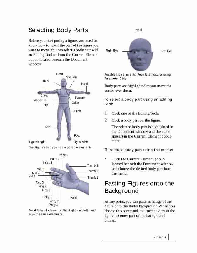
Selecting Body Parts
Before you start posing a figure, you need to know how to select the part of the figure you want to move. You can select a body part with an Editing Tool or from the Current Element popup located beneath the Document window.
Body parts are highlighted as you move the cursor over them.
To select a body part using an Editing Tool:
1 Click one of the Editing Tools.
2 Click a body part on the figure.
The selected body part is highlighted in the Document window and the name appears in the Current Element popup menu.
To select a body part using the menus:
• Click the Current Element popup located beneath the Document window and choose the desired body part from the menu.
Pasting Figures onto the Background
At any point, you can paste an image of the figure onto the studio background. When you choose this command, the current view of the figure becomes part of the background bitmap.
The Figure’s body parts are posable elements.
Posable hand elements. The Right and Left hand have the same elements.
Thigh
Shin
Foot
Figure’s leftFigure’s right
HeadShoulder
AbdomenHip
Chest
Neck
Forearm
Hand
Collar
Ring 2
Pinky 1
Mid 3
Index 1
Thumb 1
Hand
Thumb 2
Thumb 3
Pinky 2Pinky 3
Index 2Index 3
Mid 2Mid 1
Ring 1
Ring 3
Posable face elements. Pose face features using Parameter Dials.
Head
Left EyeRight Eye
P o s e r 4
At first glance, you might not notice the affects of applying this command. This is because the figure itself blocks the background-pasted image. However, any changes you make—such as moving the figure or camera—reveal the background image.
To paste the figure onto the studio background:
1 Choose Display menu> Paste onto Background.
2 The figure is pasted over the background image.
To clear the background:
• Choose Display menu> Clear Background Picture.
Hiding Figures
Hiding a figure makes it temporarily disappear from the Poser studio. This feature is useful when you have two figures close together, and one gets in the way when you try to select the other.
To hide a figure:
1 Click the Current Element popup and choose Body.
2 Choose Object menu> Properties. The Figure Properties dialog appears.
3 Disable the Visible option.
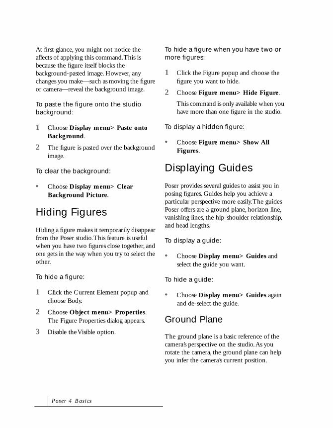
To hide a figure when you have two or more figures:
1 Click the Figure popup and choose the figure you want to hide.
2 Choose Figure menu> Hide Figure.
This command is only available when you have more than one figure in the studio.
To display a hidden figure:
• Choose Figure menu> Show All Figures.
Displaying Guides
Poser provides several guides to assist you in posing figures. Guides help you achieve a particular perspective more easily. The guides Poser offers are a ground plane, horizon line, vanishing lines, the hip-shoulder relationship, and head lengths.
To display a guide:
• Choose Display menu> Guides and select the guide you want.
To hide a guide:
• Choose Display menu> Guides again and de-select the guide.
Ground Plane
The ground plane is a basic reference of the camera’s perspective on the studio. As you rotate the camera, the ground plane can help you infer the camera’s current position.
P o s e r 4 B a s i c s

The display style of the ground place can be the same as the document or figure, or it can have its own element display style. Using the Wireframe style, the ground plane is a grid. Using the Flat Shaded display style, the ground plane is a solid color. When tracking or moving, the ground plane is displayed in Wireframe.
Head Lengths
The head lengths guide references the figure’s height. You may want to use this guide when body shaping.
Horizon Line
The horizon line provides a reference to the studio’s horizon. When you use the x, y, and z orbit controls to move the camera, you can see how far you’ve gone by checking the horizon line.
The horizon line is especially helpful in creating perspective between two figures when one figures is in the distance. Arrange the figures in the same relationship to the horizon line.
For example, if the horizon line crosses at the center of the front figure’s chest, arrange the distant figure so that the horizon crosses its chest at the same position. This arrangement contributes to the sense that all figures have their feet on the ground.
Hip-Shoulder Relationship
The hip to shoulder relationship shows the alignment between the figure’s upper and lower body. This guide helps you see the side-to-side, bend, and twist in the hip, abdomen, and chest. To see a particular aspect, try a different camera view.
The ground plane, shown in wireframe display.
Figures arranged in relation to the horizon line.
P o s e r 4

Vanishing Lines
Vanishing lines are an artistic technique for achieving realistic perspective. In Poser, the vanishing lines guide provides a reference of the perspective.Vanishing lines are helpful when matching the view of the figure with the perspective in a background image.
Undoing Operations
You can reverse the effects of your last action using the Undo command.
To undo an operation:
• Choose Edit menu> Undo or, press Command/Ctrl+Z.
Restoring Default Settings
You can restore the default settings for a body part, figure, lights, or camera. Restoring the lights resets their colors and positions. Restoring the current camera reset its scale, position, and focal length. Restoring All resets all figures, cameras, and lights.
To restore an object to its default setting:
1 Select the item from the document window or the Current Element popup.
2 Choose Edit menu> Restore> the item you want restored.
Changing Defaults
Poser uses default settings to set up a new document. As you work, however, you may achieve a position that you’d prefer over the default.
To change Poser defaults:
• Choose Edit menu> Memorize> the element you want to memorize. The new setting applies only to the current file.
The vanishing lines guide.
NoteNot all operations can be undone.
P o s e r 4 B a s i c s

PrintingThe Print command sends the contents of the Document window to your selected printer.
When printing, Poser always prints to the full page size.
Importing and ExportingImporting Content
Use the Import commands to bring the contents of other files into the current document. You can import figures, props backgrounds, surface materials such as texture and bump maps, sounds, and animations.
Importable file formats include PICT (Macintosh), TIF, JPEG, and BMP files for backgrounds or surface materials. You can import saved Poser documents for figures and props. And you can import QuickTime (Macintosh), MetaStream, VRML, and AVI (Windows) files for background footage in animations.
You can import prop geometry files in DXF, BVH, 3DMF, Wavefront OBJ, 3D Studio (Windows), and Painter3D (Detailer) formats. For details on importing props, refer to “Importing Props” on page 166.
If you import a Poser document that contains more than one figure or prop, Poser imports all of them.
To import a file:
1 Choose File menu> Import> file type.
2 Select the file you want to import in the resulting dialog.
Exporting Files
You can export the contents of the Document window to an image file at any time, from any display style. You may do this to save the wireframe image of a figure.
The exported image includes the highlighted body part and any currently displayed guides. If you don’t want to export these, deselect the figure and hide the guides before exporting.
NoteWhen in Wireframe display style
with a black background, Poser
automatically inverts the colors to
prevent printing a large black
background.
NoteIf you import a prop with textures,
place the textures in the
Poser:Runtime:Textures folder.
P o s e r 4

You can export the geometry contents of a Poser file in other formats, which you can transfer to a 3D graphics program. Transferable formats are: OBJ, 3D Studio, Detailer, DXF, RIB, Wavefront, 3DMF, and VRML/H-Anim formats.
To export a file:
1 Choose File menu> Export> file type.
2 A dialog appears asking if you want to save a Single frame or a multi-frame animation.
• If you select the Single frame option, the current frame is exported.
• If you select the Multi-frame animation option, you can specify a range of frames to export.
Select either Single frame or Multi-frame animation and click OK.
3 In the Hierarchy Selection list that appears, uncheck any items that you do
not want to be included in the export, then click OK.
4 In the Export dialog that appears, specify a filename and location and click Save.
Saving and ClosingTo save a Poser file:
1 Choose File menu> Save. The Save dialog appears.
2 Choose a name and location for your file and click Save.
NoteFor file format plugin updates,
check the Poser section of the
MetaCreations web site:
www.metacreations.com.
You can save a still or the entire animation.
The Hierarcy Selection list.
P o s e r 4 B a s i c s

To save a Poser file under a different name:
1 Choose File menu> Save As. The Save As dialog appears.
2 Choose a new name and location for your file and click Save.
To close the application:
• Choose File menu> Quit/Exit.
P o s e r 4

P o s e r 4 B a s i c s


3
Tutorial
WelcomeWelcome to the Poser 4 tutorial. This tutorial is designed to introduce all the major features and functions in Poser. Its main goal is to teach you the techniques you need to know to create realistic poses and animations.
This Tutorial chapter is divided into two sections:
• The Basics, which contains a basic tutorial to help you get started using Poser.
• Advanced Tutorials, which lead you through figure modification and animation.

The BasicsThe following set of lessons is designed to help you learn the basic operations in Poser 4. They cover topics such as setting up your workspace and working with posing tools.
Lesson 1: Setting Up a Default Workspace
When you first open Poser 4, you see the palettes and toolbars in their default position.You can change these positions, hide elements, and save the new positions as a Preferred State. The new arrangement appears the next time you open the application.
The default figure in the Document window is a Poser 3 figure. You can delete this figure and set up a new default figure as part of the Preferred State.
To delete the default figure:
1 Select either the Rotation Tool or Translate Pull Tool.
2 Click any part of the figure in the Document Window.
The selected part appears outlined in red.
3 Press the Delete key.
A dialogue box appears asking you to confirm the figure deletion.
4 Click OK.
You should now have a blank document.
The default Poser 4 workspace.
The Rotation and Pull tool are the most commonly used posing tools.
A figure with a selected part.
Tu t o r i a l

To set up an new default figure:
1 Choose Windows menu> Libraries.
The Libraries palette appears. From top to bottom the Library categories are: Figures, Poses, Faces, Hair, Hands, Props, Lights and Cameras.
2 Click the Figures button.
3 Click the sub-category menu and choose People.
4 Drag the scroll bar on the right side of the Library palette until the Casual Woman appears. All Library Entries are listed in alphabetical order.
5 Click the Casual Female, then click the Add Figure icon at the bottom of the palette.
The Libraries palette.
The Figure button.
The Casual Female in the Libraries palette.
The Add Figure icon.
P o s e r 4

You should now see a bald woman wearing casual clothing in your document window.
To add hair to a figure:
1 Move your cursor to the top of the Libraries palette. You’ll notice that there are several dots running down the left side of the palette.
2 Move the cursor over each dot. The titles change to show you the various libraries available.
The Library dots enable you to change libraries by clicking the correct dot. Clicking a large category button takes you back to the main category buttons.
3 Click the fourth dot from the top to display the Hair Library.
4 Scroll down until you see Female Hair 1.
Here, as in the Figure Library, all files are listed in alphabetical order
5 Click on Female Hair 1, then click the Change Figure icon at the bottom of the Library palette.
Your figure now has hair.
The Casual Female in the Document window.
The category dots at the top of the Libraries palette.
The Hair category dot.
The Female Hair 1 in the Libraries palette.
The Casual Female with hair.
Tu t o r i a l
Once the figure is loaded into Poser, you should set it as your Default Figure so that it loads every time you open Poser or create a new document. You can also save any changes you made to tools positions or the Document window.
To make your new figure the default:
1 Choose Edit> General Preferences.
The Preferences dialog appears.
2 Enable the Launch to Preferred State option in the Document Preferences section of the dialog.
3 Enable the Use Previous State option under the Interface Preferences section.
4 Click the Set Preferred State button.
This saves the current document to the Preferences.
5 Click OK.
Poser loads even faster if you save an empty
document as the Preferred State.
Lesson 2: Working with Cameras
You can access the cameras in Poser in several different ways. An often overlooked method of selecting a camera is by using keyboard keys. Learning a few key commands can make viewing a figure much easier.
There are two types of cameras in Poser: Conical and Isometric. Conical cameras (such as the Main, Hand and Face cameras) act like real-world cameras in that they display
perspective. Isometric cameras (such as From Top, From Left, etc.) have no perspective. When you view figures using Isometric cameras you won’t be able to rotate around the studio.
Each camera has its own center; it centers on and rotates around an object. For example, the Right Hand camera rotates around the Right Hand, and the Face camera rotates around the face. Both cameras face the center directly unless you intentionally redirect them.
Refer to “Cameras” on page 177 for more on cameras.
In this lesson you’ll explore the posing studio using the various cameras.
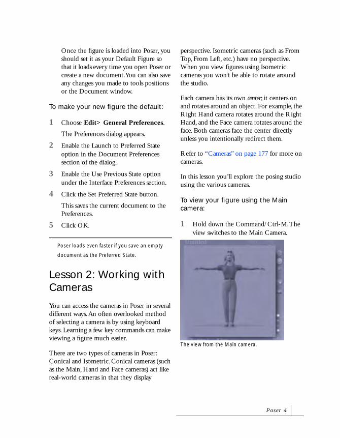
To view your figure using the Main camera:
1 Hold down the Command/Ctrl-M. The view switches to the Main Camera.
The view from the Main camera.
P o s e r 4

2 Move your cursor over the Trackball in the Camera Controls palette.
3 Drag from left to right over the Trackball. Then drag from right to left.
You’ll notice that the Main camera points at the center of the studio. You can change this default behavior by linking the camera to an object in the studio.
To link a camera to an object:
1 Make sure that the Main camera is the currently selected object.
Check Current Element menus beneath the Document Window. It should list Figure 1 and Main Camera. If not, click the menu and select the Main Camera.
2 Choose Object menu> Point At.
The Choose Actor dialog appears.
The dialog shows a visual list of all the objects in your scene.
Scroll down until you see the Head element.
3 Click Head in the list and click OK.
The Main camera now points at the Head. Note the new Parameter dial called Point At appears at the top of the list of dials.
4 Move your cursor over the Move X and Y tool on the Cameras palette and drag
The Trackball in the Camera Controls palette.
The new view of the studio.
The view of the studio with the Point At behavior applied.
Tu t o r i a l

down until the camera moves behind the figure.
No matter where you move the camera, the Head remains in the view.
With the Point At behavior the camera always points at the target object, without changing its position.
By changing the camera’s parent, you can automatically move the camera whenever you move the figure.
To change a camera’s parent:
1 Choose Object menu> Change Parent.
The Choose Parent dialog appears.
2 Choose Body from the list.
3 Click OK.
4 Press Command/Ctrl-T to switch to the Top camera.
5 Click the Translate tool.
6 Select the figure ring around the Body and move it anywhere in the Document
The new view of the studio.The new view from the Main camera using Body as its parent.
The view of the studio from the Top camera.
P o s e r 4

window. Do not click directly on the body or you will alter the pose.
7 Press Command/Ctrl-M to switch back to the Main camera
Notice that the view from the Main camera remains the same. That’s because the camera moved with the Body when you repositioned it.
Try moving the figures body again using another camera and switch back to the
Main camera. The Main camera returns to the same position.
To view the figure using the Face camera:
1 Press Command/Ctrl-(=) to switch to the Face Camera.
2 Drag left over the Trackball.
Notice that Face camera always stays with the selected figure, no matter where you move the figure.
The Face Camera is ideal for making animations that center on a single figure.
The repositioned Body.
The view of the studio from the Main camera.
The view from the Face camera.
Tu t o r i a l

To view the figure using the Top camera:
1 Press Command/Ctrl-T to switch to the Top camera.
The Top camera, like the Left, Right and Front cameras, is an Isometric camera, meaning that doesn’t show perspective.
It is designed specifically for viewing a pose rather than rendering poses. This camera is very useful for placing figures, creating animations, and locating Figures and Spotlights you may have lost in the studio.
2 Set the Top camera Scale Parameter Dial to 400% or more to get a wide view of the Poser 4 studio.
A Note on Focal Lengths
Poser’s default Cameras are set to 25mm and have all the attributes of a real-world 25mm Wide Angle Lens. You can experiment with other focal lengths such as 50mm, which resembles the human eye’s view, and 100mm, a lens favored by Portrait Photographers.
Each time you set the focal length, the Scale will also reset. Scaling Down from 100% to 25% zooms in, while scaling up from 100% to 1000% zooms out.
The view of the studio from the Top Camera.
The expanded view of the studio.
P o s e r 4

Lesson 3: Tracking Modes
A tracking mode determines how the figure looks as you move it. Fast Tracking mode displays the figure as boxes during movement. Full Tracking displays a fully rendered figure during movement.
Tracking modes help you overcome the limitations of your computer’s processing speed when posing. Faster computers can display better tracking, while slower machines benefit from less complex modes.
In this lesson you’ll learn how to choose a tracking mode.
To set a tracking mode:
1 Click one of the Tracking modes icons located on the upper right hand side of the Document window.
From the top to bottom they are: Box Tracking, Fast Tracking, and Full Tracking.
2 Click each of the mode icons and adjust the figure’s pose. Observe how different modes affect response time.
3 Use the mode that doesn’t slow down your computer’s response time.
Lesson 4: Document Display Styles
Document Display Styles in Poser have special purposes for artists, animators, and hobbyists.
In this lesson you’ll explore different styles by applying them to your figure.
To apply the Silhouette style:
1 Choose File menu> New.
2 Press Shift-Command/Ctrl-X to switch to Fast Tracking.
3 Press Command/Ctrl-1 to switch to Silhouette style.
4 Press Command/Ctrl-Option/Alt-R to Anti-Alias the document.
The Silhouette style is useful for creating masks of rendered figures, which can be used in programs s like Metacreations Painter.
The Tracking mode icons.
A figure using the Silhouette style.
Tu t o r i a l
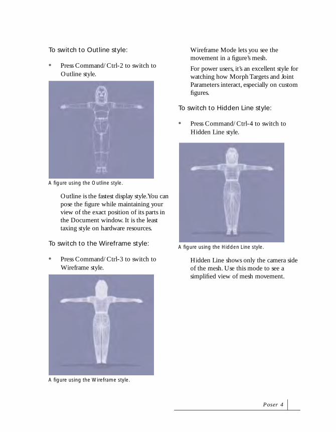
To switch to Outline style:
• Press Command/Ctrl-2 to switch to Outline style.
Outline is the fastest display style. You can pose the figure while maintaining your view of the exact position of its parts in the Document window. It is the least taxing style on hardware resources.
To switch to the Wireframe style:
• Press Command/Ctrl-3 to switch to Wireframe style.
Wireframe Mode lets you see the movement in a figure’s mesh.
For power users, it’s an excellent style for watching how Morph Targets and Joint Parameters interact, especially on custom figures.
To switch to Hidden Line style:
• Press Command/Ctrl-4 to switch to Hidden Line style.
Hidden Line shows only the camera side of the mesh. Use this mode to see a simplified view of mesh movement.
A figure using the Outline style.
A figure using the Wireframe style.
A figure using the Hidden Line style.
P o s e r 4
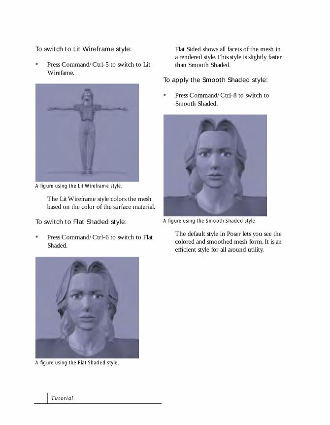
To switch to Lit Wireframe style:
• Press Command/Ctrl-5 to switch to Lit Wirefame.
The Lit Wireframe style colors the mesh based on the color of the surface material.
To switch to Flat Shaded style:
• Press Command/Ctrl-6 to switch to Flat Shaded.
Flat Sided shows all facets of the mesh in a rendered style. This style is slightly faster than Smooth Shaded.
To apply the Smooth Shaded style:
• Press Command/Ctrl-8 to switch to Smooth Shaded.
The default style in Poser lets you see the colored and smoothed mesh form. It is an efficient style for all around utility.
A figure using the Lit Wireframe style.
A figure using the Flat Shaded style.
A figure using the Smooth Shaded style.
Tu t o r i a l

To apply the Texture Shaded style:
• Press Command/Ctrl-9 to switch to Texture Shaded.
This style lets you preview the texture mapped figure.
To apply a Lined styles:
• Choose Display menu> Document Style> Flat Lined or Smooth Lined.
These styles produce color shaded representations of a model with a mesh wireframe overlaid on the surface.
In addition to being able to see the mesh, these styles can be are useful to those adept at creating custom texture maps for their models.
To apply a Cartoon style:
• Choose Display menu> Document Style> Cartoon W/Line or Cartoon.
These styles are designed with the artist in mind. Also, the new Cartoon style makes it easier to create complex masks in programs like Metacreations Painter or Photoshop.
A figure using the Texture Shaded style.
A figure using the Smooth Lined style.
A figure using the Cartoon style.
P o s e r 4

Working with LightsLights are one of the most necessary and least understood part of any 3D Program. Often they’re difficult to use. Poser’s remedy is a unique Light Controls palette that lets you intuitively manipulate lights.
There are two types of lights in Poser: Infinite and Spotlights. To use them effectively, you first need to understand the differences between the two. Infinite light illuminates one side of everything in the scene in the same way sunlight does. Spotlights point in a single direction and illuminate everything that falls with in the cone of light they produce. Poser uses Infinite lights by default.
Lesson 1: Using the Light Control
You’ll begin this lesson by deleting two of the three default lights in the Poser scene and learning the controls.
To use the Light controls:
1 On the Light Controls palette, select the circle for the light you want to delete.
2 Click the Delete Light icon.
The selected light is deleted.
3 Select another light and repeat step 2.
4 Select the remaining light.
Each light in the studio is represented by a circle on the Light Control. This example shows a selected light.
The Delete Light icon.
Tu t o r i a l
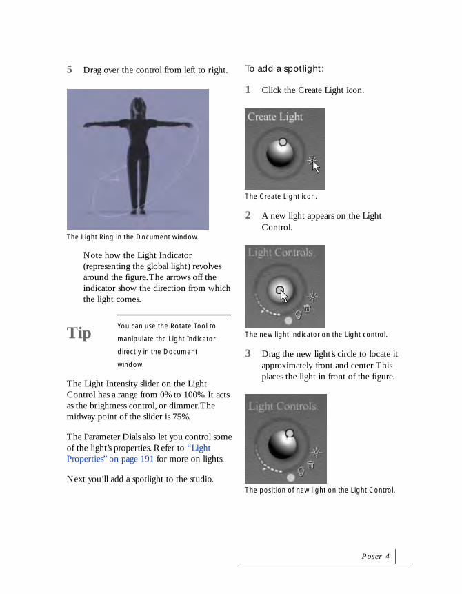
5 Drag over the control from left to right.
Note how the Light Indicator (representing the global light) revolves around the figure. The arrows off the indicator show the direction from which the light comes.
The Light Intensity slider on the Light Control has a range from 0% to 100%. It acts as the brightness control, or dimmer. The midway point of the slider is 75%.
The Parameter Dials also let you control some of the light’s properties. Refer to “Light Properties” on page 191 for more on lights.
Next you’ll add a spotlight to the studio.
To add a spotlight:
1 Click the Create Light icon.
2 A new light appears on the Light Control.
3 Drag the new light’s circle to locate it approximately front and center. This places the light in front of the figure.
The Light Ring in the Document window.
TipYou can use the Rotate Tool to
manipulate the Light Indicator
directly in the Document
window.
The Create Light icon.
The new light indicator on the Light control.
The position of new light on the Light Control.
P o s e r 4

4 Set the Light Intensity slider to approximately 75%, or the middle of the slider.
5 Click the Light Properties icon.
The Light Properties dialog appears.
6 Enable the Spotlight option.
You now have a new spotlight, you can control how it behaves by applying the Point At function to it.
To apply the Point At behavior to a light:
1 Make sure your new spotlight is the selected element.
2 Choose Object menu> Point At.
The Choose Actor dialog appears.
3 Choose Head from the Select a Scene Element list.
4 Set the yTrans Parameter dial to between 0.900 and 1.000.
5 Set the zTrans dial -1.0.
The Spotlight’s Indicator moves out from behind the camera to behind the figure. Notice how it always remains pointed at the Head.
6 Adjust the values of the x, y or zRotate Parameter dials.
You’ll notice that the Spotlight doesn’t rotate like an Infinite light. Infinite lights
The Light Intensity slider set to 75%.
The Light Properties icon.
The Spotlight option on the Light Properties dialog.
The Spotlight’s indicator in the Document window.
Tu t o r i a l

rotate around the center of the studio. Spotlights rotate around the center of the light object.
Using Poser’s ToolsThe lessons in this section teach you how to work with the most commonly used Posing tools and the Parameter Dials.
Lesson 1: The Parameter Dials
The simplest way of posing a figure is by selecting each individual part, and using the Parameter Dials to move it into the desired position.
A much faster way of posing is to use the four main posing tools directly on the figure in the Document window. However, this method requires considerable practice.
This lesson leads you through the process of posing a figure using the Parameter Dials.
To pose by typing in numerical values:
1 Click the Translate/Pull tool.
2 Select the Right Shoulder in the Document window.
A series of parameter dials appear.
3 Click the value on the Bend dial.
4 Type 80 in the field that appears.
The Translate/Pull tool.
The Right Shoulder selected on the figure.
The Bend dial.
The Bend dial.
P o s e r 4
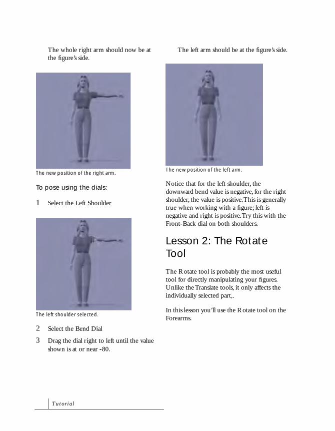
The whole right arm should now be at the figure’s side.
To pose using the dials:
1 Select the Left Shoulder
2 Select the Bend Dial
3 Drag the dial right to left until the value shown is at or near -80.
The left arm should be at the figure’s side.
Notice that for the left shoulder, the downward bend value is negative, for the right shoulder, the value is positive. This is generally true when working with a figure; left is negative and right is positive. Try this with the Front-Back dial on both shoulders.
Lesson 2: The Rotate Tool
The Rotate tool is probably the most useful tool for directly manipulating your figures. Unlike the Translate tools, it only affects the individually selected part,.
In this lesson you’ll use the Rotate tool on the Forearms.
The new position of the right arm.
The left shoulder selected.
The new position of the left arm.
Tu t o r i a l

To pose using the Rotate tool:
1 First, switch to the From Left camera by pressing Command/Ctrl-( ; ). This makes rotating easier.
You are now looking at the figure’s right side.
2 Click the Rotate Tool.
3 In the Document Window, select the Right Forearm.
4 Place the cursor directly over the selected forearm and drag to the right until it is extended in front of the figure.
5 Press Command/Ctrl-( ’ ) to switch to the From Right Camera.
You’re now looking at the left side of the figure.
NoteBecoming used to quickly
changing cameras makes posing
a much simpler task
The Rotate tool.
The selected Right Forearm.
Drag to the right until the arm is in the position shown.
The figure shown through the From Right Camera.
P o s e r 4

6 Select the Left Forearm with the Rotate tool.
7 Place your cursor behind the figure and drag to the left.
The Forearm bends up.
8 Place the cursor to the left of the figure and drag up. The Forearm follows.
Now you have used two methods of working with the Rotate Tool. You can use the tool directly on the selected part, or you can drag the tool across the workspace and the part will follow. This is true of all four main Posing tools: Rotate, Twist, Translate/Pull and Translate In/Out.
Lesson 3: The Twist Tool
The Twist Tool does exactly what its name implies, it twists body parts. This is accomplished by selecting the part and drawing the tool across the screen. It is an extremely useful tool for creating realistic poses quickly.
The selected Left Forearm.
Drag left until the forearm is in the position shown.
Drag up until the forearm is in the position shown.
Tu t o r i a l

To use the Twist tool:
1 First, press Command/Ctrl-M to switch back to the Main Camera.
2 Select the Twist tool.
3 Move your cursor over the faint circle that surrounds the figure. When you’re directly over it, the circle turns white.
4 Click and hold the highlighted circle; it turns red.
5 Move your cursor to the left side of the Document window and to the right until you see the figure at a three quarter face.
Check the yRotate dial value. It should be at about 45 degrees.
The figure shown through the Main Camera.
The Twist tool.
A figure with the Figure ring highlighted.
The rotated figure.
P o s e r 4

6 Select the Hips with the Twist tool.
7 Drag to the left until the figure is once again directly facing the camera.
8 Select the Neck and drag to the left.
The Twist dial should be near -16 degrees.
9 Select the Head and drag to the left.
The Twist dial should be near -16 degrees.
Lesson 4: The Translate and Chain Break Tools
The Translate/Pull, In/Out and Chain Break tools are some of the most powerful direct posing tools available to you. Used together, they can quickly generate any pose. Once you have a pose, you can then fine-tune the pose using the Parameter Dials. In this lesson, you’ll explore posing using just these three tools.
To pose using the Translate/Pull tool:
1 First, save anything you wish to keep from the last tutorial, and create a new document (File menu> New).
2 Select the Translate/Pull tool
The Hips selected with the Twist tool.
The selected Neck.
The final position of the Head.
The Translate/Pull tool.
Tu t o r i a l
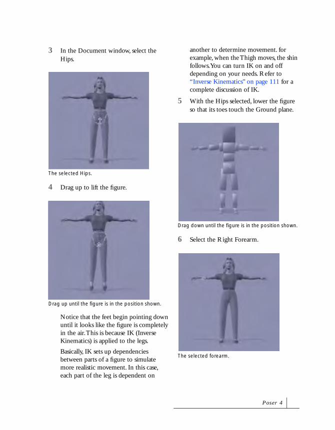
3 In the Document window, select the Hips.
4 Drag up to lift the figure.
Notice that the feet begin pointing down until it looks like the figure is completely in the air. This is because IK (Inverse Kinematics) is applied to the legs.
Basically, IK sets up dependencies between parts of a figure to simulate more realistic movement. In this case, each part of the leg is dependent on
another to determine movement. for example, when the Thigh moves, the shin follows. You can turn IK on and off depending on your needs. Refer to “Inverse Kinematics” on page 111 for a complete discussion of IK.
5 With the Hips selected, lower the figure so that its toes touch the Ground plane.
6 Select the Right Forearm.
The selected Hips.
Drag up until the figure is in the position shown.
Drag down until the figure is in the position shown.
The selected forearm.
P o s e r 4

7 Pull the Forearm to the right, then up and down.
Notice that this movement affects more than just the Forearm. You’re pulling the figure all the way down to the Abdomen. You’ll see what’s causing this behavior when you select the Chain Break tool.
The Chain Break tool lets you assign chain breaks to your figure. Chain breaks tell the Translate tools how far to affect the position of the figure. You’ll see one chain break on the Hips, and one on the Head. Since the Hips are the figure’s root part, you cannot turn the chain break off there. However, you can turn off the head’s Chain Break.
Next you’ll explore assigning chain breaks.
To assign chain breaks:
1 Select the Chain Break Tool.
A chain break icon appears over every chain break in the figure.
2 Click on each Collar to assign a chain break.
3 Click each Thigh to assign two more breaks.
You’ll notice that you can assign chain breaks to both collars but not to the Thighs. This is because IK is turned on.
The Chain Break tool.
The default chain breaks on a figure.
A chain break assigned to the Collar.
Tu t o r i a l

4 Choose Figure menu> Use Inverse Kinematics> Left Leg then choose Right Leg. IK is turned off when there is no checkmark next to a menu item.
5 Now, try assigning chain breaks to the legs.
Next, you’ll explore using the Translate In/Out tool.
To use the Translate In/Out tool:
1 Click the Translate In/Out tool.
2 Select the Right Foot.
3 Drag up.
The Right Foot and leg move away from you.
4 Select the Chest.
5 Drag down.
The figure appears to bow.
6 Press Command/Ctrl-Z to undo the last command.
7 Choose Figure menu> Use Inverse Kinematics> Left Arm then choose Right Arm to turn IK on in the arms.
The Translate In/Out tool.
The Right Foot selected.
The position of the Right Foot after the move.
The new position of the Chest.
P o s e r 4

IK is enabled when a checkmark appears next to a menu item.
When you enable IK, any chain breaks you assign to the arms are deleted. IK on the Arms doesn’t affect the Collar chain breaks you assigned earlier.
8 Select the Chest again and drag down.
With IK turned on, the Hands resist movement when you translate a body part that affects them. It appears as if they are holding onto something.
PosingIn this section you’ll learn several ways of posing that expand on what you have learned in the previous sections.
Lesson 1: Creating Poses
In this lesson, you’re going to use everything you’ve learned so far about Poser’s tools to create a simple, yet realistic pose: Hands on Hips.
You’ll use the tools as well as the Symmetrical command to quickly set-up the pose. Keep in mind that although the human body looks symmetrical, it’s rarely positioned in a symmetrical manner. Even a very symmetrical pose like placing both hands on your hips may not look entirely natural if you just reverse the values from left and right. That’s why you’ll also use the tools to set up a more natural position for the figure’s limbs.
Posing using the Posing Tools can be somewhat imprecise for the new user; you may want to use the Parameter Dials to reposition body parts. The Parameter Dial values used in the pose are listed so you can duplicate it using only the dials.
Once you achieve the pose described here, use what you’ve learned to make additional adjustments so that the final pose looks right to you.
To assign Chain Breaks to a figure:
1 Open a new document.
The default Casual Female appears.
2 Choose Figure menu> Use Limits.
This command prevents movement of body parts into an unnatural position.
3 Press Command/Ctrl-M to select the Main Camera.
4 Select the Chain Break tool.
The position of the figure with IK turned off.
The Chain Break tool.
Tu t o r i a l

5 Assign a Chain Break to the Chest.
To position the right arm:
1 Select the Twist tool.
2 Select the figure’s Right Shoulder.
3 Place the Twist tool over the background in the Document window.
4 Drag right so that the arm twists to 45°.
The Right Shoulder’s Twist parameter should be set at approximately 45°.
5 Select the Right Forearm and drag right.
The Twist dial should be at 14°.
6 Select the Right Collar and drag right.
The new Chain Break on the figure.
The Twist tool.
The Right Shoulder should be in the position shown.
The Right Forearm should be in the position shown.
P o s e r 4

The Twist dial should be at 25°.
7 Select the Rotate tool.
8 Select the Right Hand.
9 Move the Rotate tool to a blank area of the Document window and drag right to bend the Right Hand.
The Bend dial should read about -75°.
10 Select the Right Forearm.
11 Set the Bend dial to 95°.
12 Set the Side-Side dial to 5°.
13 Using the Rotate tool, select the Right Shoulder.
14 Set Bend to 26°.
15 Select the Right Collar.
The Right Collar should be in the position shown.
The Right Hand after positioning.
The new position of the Right Forearm.
The new position of the Right Shoulder.
Tu t o r i a l

16 Set Bend to 25°.
Once you’re done, your parameter dials should read as follows:
Right Collar:
• Twist = 25°
• Bend = 25°
Right Shoulder:
• Twist = 45°
• Bend = 26°
Right Forearm:
• Twist = 14°
• Side-Side= 5°
• Bend = 95°
Right Hand:
• Bend = -75°
To apply the right arm pose to the left arm:
1 Choose Figure menu> Symmetrical> Right Arm to Left Arm.
2 A dialog appear asking if you want to copy the joint zone’s setup also. Click No.
3 Save the file.
Your pose is almost finished, but it still looks a little unnatural. Next you’ll shift the figure’s weight.
To achieve a natural standing position:
1 Click the Translate/Pull tool.
2 Select the Right Foot.
The repositioned Right Collar.
The symmetrical pose.
P o s e r 4
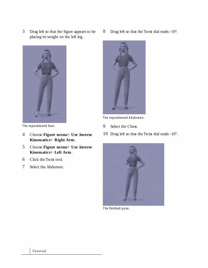
3 Drag left so that the figure appears to be placing its weight on the left leg.
4 Choose Figure menu> Use Inverse Kinematics> Right Arm.
5 Choose Figure menu> Use Inverse Kinematics> Left Arm.
6 Click the Twist tool.
7 Select the Abdomen.
8 Drag left so that the Twist dial reads -10°.
9 Select the Chest.
10 Drag left so that the Twist dial reads -10°.
The repositioned foot.
The repositioned Abdomen.
The finished pose.
Tu t o r i a l

Lesson 2: Adding Poses to the Pose Library
Once you create a Pose, you can add it to the library for future use. For easy access, you’ll also create a new category for your custom poses.
To add a pose to the library:
1 Press Command/Ctrl-Shift-B to open the Libraries palette.
2 Click the Poses button.
The default Action Sets library appears.
3 Click the Sub-Category menu and choose Add New Category.
A Save dialog appears.
4 Enter a name for your personal library and press Enter.
5 A dialog appears asking if you want to save a Single frame or a multi-frame animation. Select Single frame and click OK.
A new category appear in the palette.
6 Click the Add to Library (+) icon at the bottom of the palette to add a custom pose.
7 Enter a name for the pose, such as Hands on Hips or Posed Arms 01.
The Libraries palette.
The Poses button.
The Sub-Category menu.
The Add to Library icon.
P o s e r 4
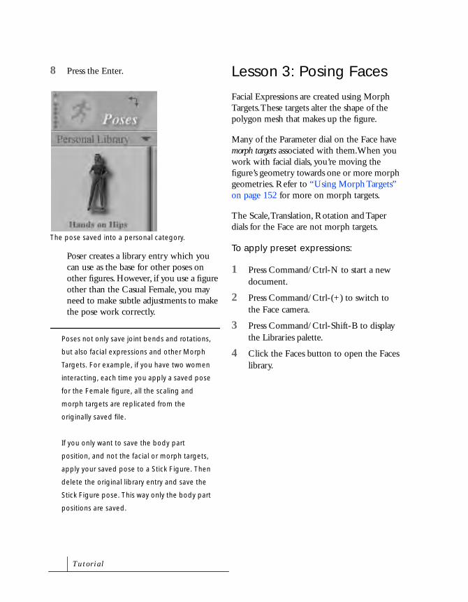
8 Press the Enter.
Poser creates a library entry which you can use as the base for other poses on other figures. However, if you use a figure other than the Casual Female, you may need to make subtle adjustments to make the pose work correctly.
Poses not only save joint bends and rotations,
but also facial expressions and other Morph
Targets. For example, if you have two women
interacting, each time you apply a saved pose
for the Female figure, all the scaling and
morph targets are replicated from the
originally saved file.
If you only want to save the body part
position, and not the facial or morph targets,
apply your saved pose to a Stick Figure. Then
delete the original library entry and save the
Stick Figure pose. This way only the body part
positions are saved.
Lesson 3: Posing Faces
Facial Expressions are created using Morph Targets. These targets alter the shape of the polygon mesh that makes up the figure.
Many of the Parameter dial on the Face have morph targets associated with them.When you work with facial dials, you’re moving the figure’s geometry towards one or more morph geometries. Refer to “Using Morph Targets” on page 152 for more on morph targets.
The Scale, Translation, Rotation and Taper dials for the Face are not morph targets.
To apply preset expressions:
1 Press Command/Ctrl-N to start a new document.
2 Press Command/Ctrl-(+) to switch to the Face camera.
3 Press Command/Ctrl-Shift-B to display the Libraries palette.
4 Click the Faces button to open the Faces library.
The pose saved into a personal category.
Tu t o r i a l
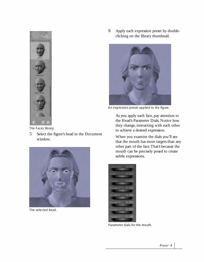
5 Select the figure’s head in the Document window.
6 Apply each expression preset by double-clicking on the library thumbnail.
As you apply each face, pay attention to the Head’s Parameter Dials. Notice how they change, interacting with each other to achieve a desired expression.
When you examine the dials you’ll see that the mouth has more targets than any other part of the face. That’s because the mouth can be precisely posed to create subtle expressions.
The Faces library.
The selected head.
An expression preset applied to the figure.
Parameter dials for the mouth.
P o s e r 4

Keep in mind that dials such as Smile affect primarily the upper lip, as opposed to the Frown dial which affects the lower lip. Slightly fewer dials apply to the brows—three for each.
You’ll notice that here is no target for a Furled
Brow. To accomplish this, select the Worry Left
and Worry Right dials and enter Negative 0.5
in each.
After exploring the facial controls, you’re ready to create your own expression. Next, you’ll create the face of an angry woman using the target dials.
To create an expression:
1 Select the head.
2 Enter Open Lips= 0.431 to tighten the lips.
3 Set Smile= -0.128.
4 Set Mouth F= 0.152. This pulls in the lower lip.
5 Set Mouth M= 0.234 to tighten the lips laterally.
6 Set Blink Right and Blink Left = 0.2 to narrow the eyes slightly.
7 Click the Add to Library (+) button at the bottom of the Libraries palette to save the file to the Faces library.
RenderingRendering is the process of converting your 3D figure into a 2D image or animation. There are several options you can set for a rendering session. All available options are displayed in the Rendering Options dialog.
To set up a rendering session:
1 Choose File menu> Open.
2 Locate the file Tutorial: paper-airplane.pz3.
NoteBe sure to use the decimal point
in each of these numbers. If, for
instance, you enter -431 instead
of -0.431 for the Open Lips, you
will severely distort your figure—
she’ll be very angry.
The completed expression.
Tu t o r i a l

3 Press Command/Ctrl-Y.
The Render Options dialog appears.
4 Make sure the Anti-Alias box is enabled.
This gives you a clean render, but may bog down slower machines.
5 Disable the Cast Shadows option.
This will speed things up.
6 Click Render Now.
In true WYSIWYG fashion, what you see in the document window is exactly what is produced.
Depending on where the main camera is positioned when you saved the document, this may serve as your final render. However let’s assume you’re not satisfied with the results.
To reposition the camera:
1 Select the Main Camera.
2 Choose Object menu> Point At.
The paper-airplane file in the Document window. The rendered file.
The main camera icon.
P o s e r 4

3 The Choose Actor dialog appears.
4 Select the Teacher figure’s Head element from the list, then click OK.
5 Use the Scale Parameter dial to rescale the camera so that both figures fill the screen.
6 Move the Camera using the X and Z tool on the Camera Controls.
The camera will always point at the Teacher.
7 Use the Move X and Y tool to adjust the elevation of the camera.
8 Render the file again.
9 When the test render produces good results, enable Cast Shadows in the
Both figures in the scene.
The view through the repositioned camera.
The view through the elevated camera.
The test render
Tu t o r i a l

Render Options dialog (Command/Ctrl-Y) and render the file once more.
There is no set rule of what makes a good render. Success is subjective. Poser can produce varied results using its custom rendering engine. Try exploring other rendering options using this file and other personal files.
Advanced TutorialsThe following tutorials are designed to be both challenging and rewarding. Do not plan on completing these tutorials quickly; work methodically so that you become comfortable exercising Poser’s most powerful features.
The scenes you create in these tutorials can be dropped into most contemporary films, or can be the centerpiece of a major production. The goal is to provide you with experience using Poser’s animation tools that will enable you to produce increasingly complex and extravagant scenes.
At any time while working with these tutorial, feel free to experiment. Each section overlaps and explores different features, as well as different aspects of the same features. This allows you to develop a well rounded understanding of how to accomplish desired effects.
Character Creation and Animation
Lesson 1: Creating a Clown from Scratch
Use of props and texture maps are essential to creating a good character. This lesson walks you through the processes of scaling body parts, applying props, and texture mapping to create a basic clown figure from scratch.
You’ll also animate your clown and place him in a scene to interact with props and other figures.
To select a base figure:
1 Click the Figures icon on the Libraries palette
The default People sub-category appears.
The final render.
P o s e r 4
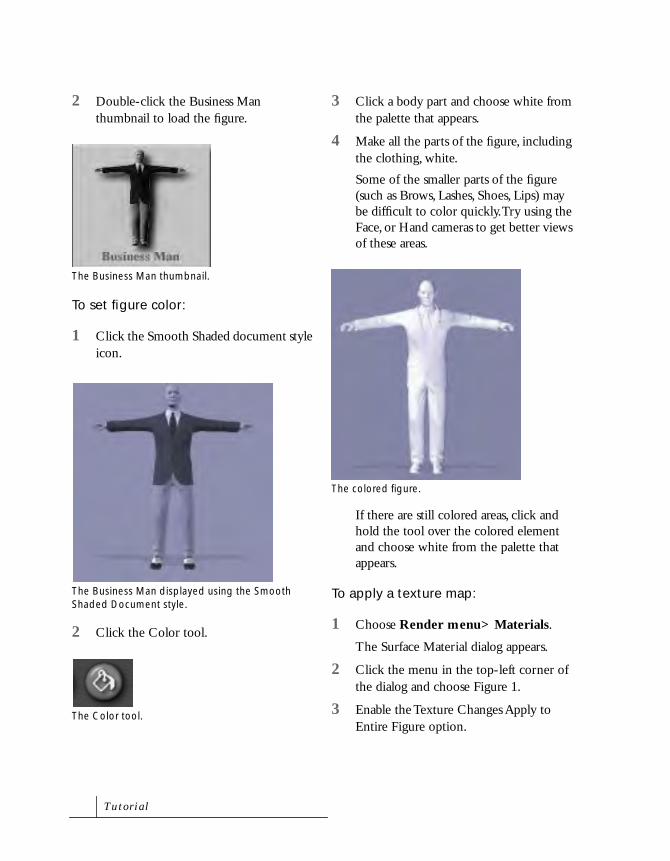
2 Double-click the Business Man thumbnail to load the figure.
To set figure color:
1 Click the Smooth Shaded document style icon.
2 Click the Color tool.
3 Click a body part and choose white from the palette that appears.
4 Make all the parts of the figure, including the clothing, white.
Some of the smaller parts of the figure (such as Brows, Lashes, Shoes, Lips) may be difficult to color quickly. Try using the Face, or Hand cameras to get better views of these areas.
If there are still colored areas, click and hold the tool over the colored element and choose white from the palette that appears.
To apply a texture map:
1 Choose Render menu> Materials.
The Surface Material dialog appears.
2 Click the menu in the top-left corner of the dialog and choose Figure 1.
3 Enable the Texture Changes Apply to Entire Figure option.
The Business Man thumbnail.
The Business Man displayed using the Smooth Shaded Document style.
The Color tool.
The colored figure.
Tu t o r i a l

4 Click the Load button in the Texture Map section of the dialog.
An Open dialog appears.
5 Locate the file Tutorial: CLOWN01, and click Open.
6 Click OK in the Surface Materials dialog.
7 Click the Texture Shaded icon to see the new texture.
To add a prop:
1 Click the Props icon at the top of the Libraries palette.
2 Select the Prop Types category.
3 Double-click the Ball thumbnail to load the Ball object.
4 Click Color tool.
5 Click the ball and make it red.
To position the prop:
1 Drag to the right over the Camera controls until the From Left camera icon appears.
The Texture Shaded icon.
The new texture map applied to the figure.
The Prop icon on the Libraries palette.
The Ball thumbnail.
The Color tool.
The From Left camera icon.
P o s e r 4

2 Click the Translate/Pull tool.
3 Position the ball in front of the clown’s face.
4 With the ball selected, set the Scale dial to 22%.
5 Use the Translate/Pull tool to move the ball over the clown’s nose.
6 Press Command/Ctrl-F to switch to the Front camera.
7 Check the lateral position of the ball on the nose.
To set the prop parent:
1 Choose Object menu> Change Parent to display the Choose Parent dialog.
The Translate/Pull tool.
Position the ball as shown.
The scaled ball.
Position the ball over the nose as shown.
The clown displayed using the Front camera.
Tu t o r i a l

The dialog shows a visual list of all the objects in your scene.
2 Click Head in the list and click OK.
3 Press Command/Ctrl-M to switch to the Main camera.
4 Review your work from several angles.
5 Save the clown to the Figure library in the Libraries palette. Refer to “Lesson 2: Adding Poses to the Pose Library” on page 81 for instructions.
Lesson 2: Making the Clown Walk
This lesson leads you through the process of creating and editing keyframes to create a walking motion.
You can use this animation later with the Walk Designer.
Setting the First Walking Frame
To begin you need to set up a starting pose.
To set up a starting pose:
1 Make sure your clown document is still open.
2 Double-click the handle at the bottom of the screen to open the Animation controls.
3 Make sure the frame counter is set to 1 of 30.
4 Press Command/Ctrl-M to switch to the Main camera.
5 Select the Right Shoulder.
6 Set the Bend value to 78°.
7 Select the Left Shoulder.
The Animation controls.
The clown displayed using the Main camera.
The bent Right Shoulder.
P o s e r 4

8 Set the Bend value to -78°.
9 Select the Abdomen and set Side-Side to 3.
10 Select the Chest and set Side-Side to 3.
11 Press Command/Ctrl-(’ ) to switch to the From Right camera.
12 Click the Translate/Pull tool.
13 Select the Left Foot and move it forward.
14 Select the Right Foot and move it back.
The adjusted Left Shoulder.
The adjusted Abdomen and Chest.
The Translate/Pull tool.
The re-positioned Left Foot.
The final pose.
Tu t o r i a l

Adding Keyframes
Once you have a starting point, you’ll create an action by changing the pose over time and saving the changes as keyframes. A keyframe stores a point in time where action occurs. Here you’ll store changes in foot positions as keyframes to create a walking motion. Refer to “Adding and Deleting Keyframes” on page 213 for more on setting up keyframes.
To add frames:
1 Press Command/Ctrl-M to switch to the Main camera.
2 In the Animation controls, drag the small triangle (called the Scrubber) to Frame 16.
3 Choose Figure menu> Symmetry> Swap Right and Left.
The figure’s left foot moves back and the right foot moves forward.
4 Click the Add Keyframe (+) button to keyframe the new position.
5 Move the Scrubber to Frame 15.
6 Click the Add Keyframe (+) button to insert a keyframe.
Editing Keyframes
Now that you have a number of keyframes, you’ll learn how to edit them in the Animation palette to create more realistic motion.
The clown viewed from the Main camera.
The Scrubber at Frame 16.
The left foot position sapped for the right foot position.
The Add Keyframe button.
P o s e r 4

To edit frames:
1 Click the Edit Keyframes button.
The Animation palette appears. The palette displays all the animatable attributes in the studio and all the keyframes you’ve created. Refer to “Editing Animations” on page 213 for more on this palette.
2 Drag the scroll bar all the way to the top.
3 Click the green keyframes for Frame 15 and drag all the way to the bottom to select the keyframes for all the attributes. The selection is bordered with a white line.
Be sure only the green keyframes of Frame 15 are selected. Be very careful not to select anything but Frame 15.
4 Drag all of selected keyframes to Frame 30.
The Animation palette.
Scroll bar
All the Frame 15 keyframes selected.
Frame 15 keyframes moved to Frame 30.
Tu t o r i a l
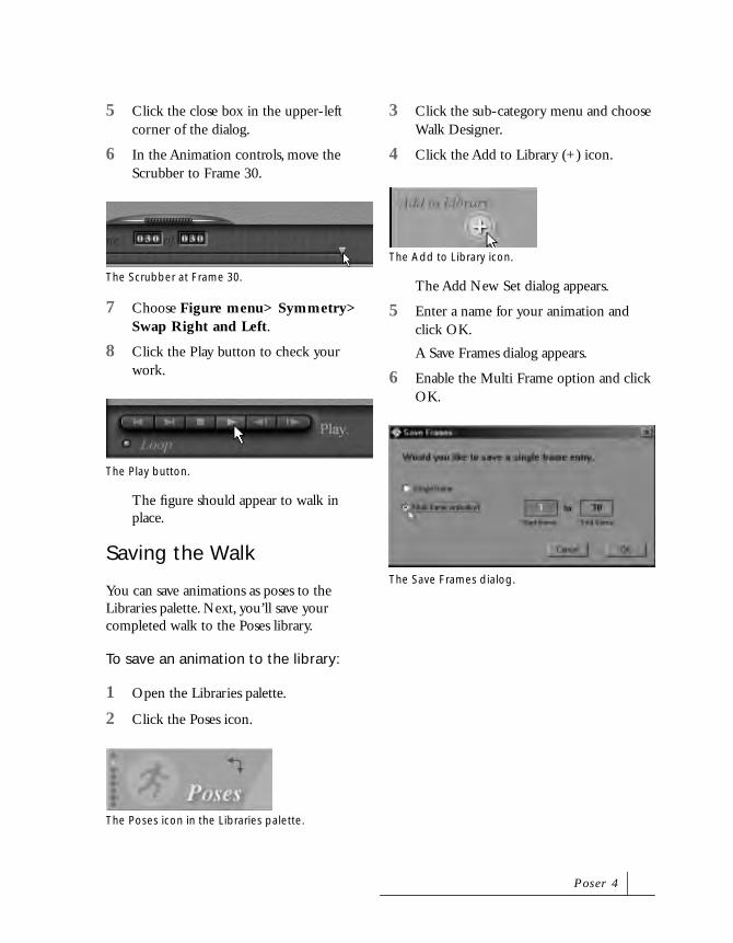
5 Click the close box in the upper-left corner of the dialog.
6 In the Animation controls, move the Scrubber to Frame 30.
7 Choose Figure menu> Symmetry> Swap Right and Left.
8 Click the Play button to check your work.
The figure should appear to walk in place.
Saving the Walk
You can save animations as poses to the Libraries palette. Next, you’ll save your completed walk to the Poses library.
To save an animation to the library:
1 Open the Libraries palette.
2 Click the Poses icon.
3 Click the sub-category menu and choose Walk Designer.
4 Click the Add to Library (+) icon.
The Add New Set dialog appears.
5 Enter a name for your animation and click OK.
A Save Frames dialog appears.
6 Enable the Multi Frame option and click OK.
The Scrubber at Frame 30.
The Play button.
The Poses icon in the Libraries palette.
The Add to Library icon.
The Save Frames dialog.
P o s e r 4

7 Your animation is saved as a 30 frame preset in the Walk Designer category.
Lesson 3: The Walk Designer
The Walk Designer lets you set up various parameters to automatically create a realistic walking motion. In this lesson you’ll use the file you created in the previous lesson in conjunction with the Walk Designer to make your clown move.
To set up the walk animation:
1 Choose File menu> New to start with an empty file.
2 Open the Libraries palette and click the Figures icon.
3 Double-click the clown figure you saved earlier.
The default figure is replaced with the clown.
4 Choose Figure menu> Create Walk Path.
A new path appears in the Document window.
5 Make sure the Scrubber in the Animation Controls is at Frame 1.
6 Open the Libraries palette and click the Pose icon.
The clown in the Libraries palette.
The clown figure in the Document window.
A new Walk Path in the Document window.
Tu t o r i a l

7 Click the sub-category menu and choose Tutorial.
8 Double-click the Clown-Start pose to apply it to the clown.
9 Display the Animation palette.
10 Move the Scrubber to Frame 30.
11 In the Libraries palette, double-click the Clown Finish pose to apply it.
12 Click the Current Element popup at the bottom of the Document window and choose Cameras> Top Camera.
13 Set Scale to 400%. You should able to see the entire scene.
14 Move the camera up or down to see the whole path.
15 Select the Walk Path using the Translate/Pull tool.
It looks like a slight backward “S” extending out in front of the figure.
The Clown Start pose in the Library.
The Clown Finish pose in the Library.
The Element menu.
The clown viewed from the top.
The scaled view of the clown.
P o s e r 4
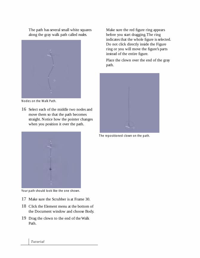
The path has several small white squares along the gray walk path called nodes.
16 Select each of the middle two nodes and move them so that the path becomes straight. Notice how the pointer changes when you position it over the path.
17 Make sure the Scrubber is at Frame 30.
18 Click the Element menu at the bottom of the Document window and choose Body.
19 Drag the clown to the end of the Walk Path.
Make sure the red figure ring appears before you start dragging. The ring indicates that the whole figure is selected. Do not click directly inside the Figure ring or you will move the figure’s parts instead of the entire figure.
Place the clown over the end of the gray path.
Nodes on the Walk Path.
Your path should look like the one shown.
The repositioned clown on the path.
Tu t o r i a l

To set up a walk in the Walk Designer:
1 Press Command/Ctrl-Shift-S to open the Walk Designer.
2 Click the walk button to see the current walk style in action.
Click the stop button to stop the action.
3 Scroll the Blend Styles section of the dialog until the Clown walk is visible.
4 Set Clown to 100%.
5 Click Apply.
The Apply Walk dialog appears.
You are about to apply the walk to the figure.
Once you’re done with the Walk Designer, the
only real way to fix errors is to start from
scratch (beginning from Lesson 3).
6 Make sure the following defaults are set in the dialog:
• Start Frame = 1
• End Frame = 120
• Figure = Figure 1
• Walk In Place = Disabled
• Cycle Repeat = Empty
• Path = Path_1
• Always Complete last step = Enabled
• Transition from pose at path start in 15 Frames = Enabled
• Transition to pose at path start in 15 Frames = Enabled
• Align head to = Disabled
The Walk Designer.
The Apply Walk dialog.
P o s e r 4

7 Once all parameters in the Walk Designer are set, click OK.
8 Click Done to close the Walk Designer.
The new walk is applied to the clown.
9 Save the file with the name: CLOWN-ANI.
Lesson 4: Keyframe Editing
So far, you’ve created a waddling clown that appears to fall over something invisible at the end of the Walk Path. There are two missing elements: the object the clown fell over, and the cause of his fall. By editing the animation and adding props, you can create the story behind the clown’s actions.
First. you’ll create a back up file to preserve your work so far.
To create a back up file:
1 Open the file you saved at the end of Lesson 3.
2 Choose File menu> Save As.
3 Rename to the file to CLOWN-ANI01.
Now you have a back-up of your original animation.
Consider using a compression utility to
archive the original clown-walk.pz4 file. This
will save hard drive space and future
headache’s. You can continue to add
completed lesson file to the archive as you
work through the rest of the tutorial.
Next, you’ll set up an animated expression for the clown.
To set up an animated expression:
1 Click the Edit Keyframe button on the Animation controls.
The Animation palette appears.
2 Click the Head label on the left side of the dialog.
3 Select all the keyframes from 2 to 105.
The Edit Keyframes button.
The Head element selected.
Head keyframes selected.
Tu t o r i a l

4 While still pressing the mouse button, drag up one line to include the Neck frames in your selection.
5 Press Delete.
6 With the frames still selected, click the Linear Section button.
This is important for any expression changes applied face during the animation.
7 Select Head keyframe 1.
8 Close the Animation palette.
9 Open Libraries palette.
10 Click the Faces icon at the top of the palette.
11 Click the sub-category menu and choose Add New Category.
The New Category dialog appears.
12 Enter Clown Faces and click OK.
13 Click the Add to Library button to add the clown’s face into the library.
14 Move the Scrubber to Frame 105.
15 Apply the face preset you just saved to the clown.
Next, you’ll add another actor to your scene.
To import a Poser document:
1 Choose File menu> Import> Poser Document.
An Open dialog appears.
2 Locate the file Tutorial: TRAPESE ARTIST WALK.
Both Head and Neck keyframes selected.
Linear Section button.
Head keyframe 1 selected.
The Face icon on the Libraries palette.
Your clown face in the library.
P o s e r 4
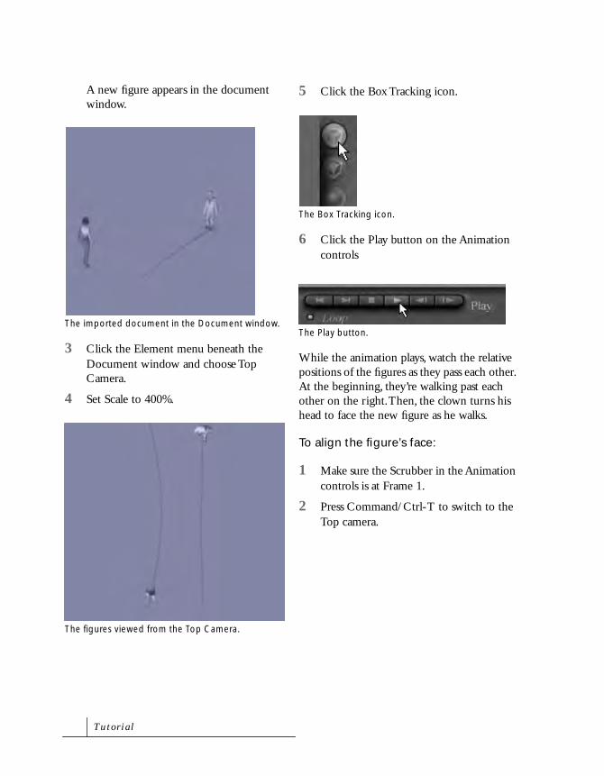
A new figure appears in the document window.
3 Click the Element menu beneath the Document window and choose Top Camera.
4 Set Scale to 400%.
5 Click the Box Tracking icon.
6 Click the Play button on the Animation controls
While the animation plays, watch the relative positions of the figures as they pass each other. At the beginning, they’re walking past each other on the right. Then, the clown turns his head to face the new figure as he walks.
To align the figure’s face:
1 Make sure the Scrubber in the Animation controls is at Frame 1.
2 Press Command/Ctrl-T to switch to the Top camera.
The imported document in the Document window.
The figures viewed from the Top Camera.
The Box Tracking icon.
The Play button.
Tu t o r i a l
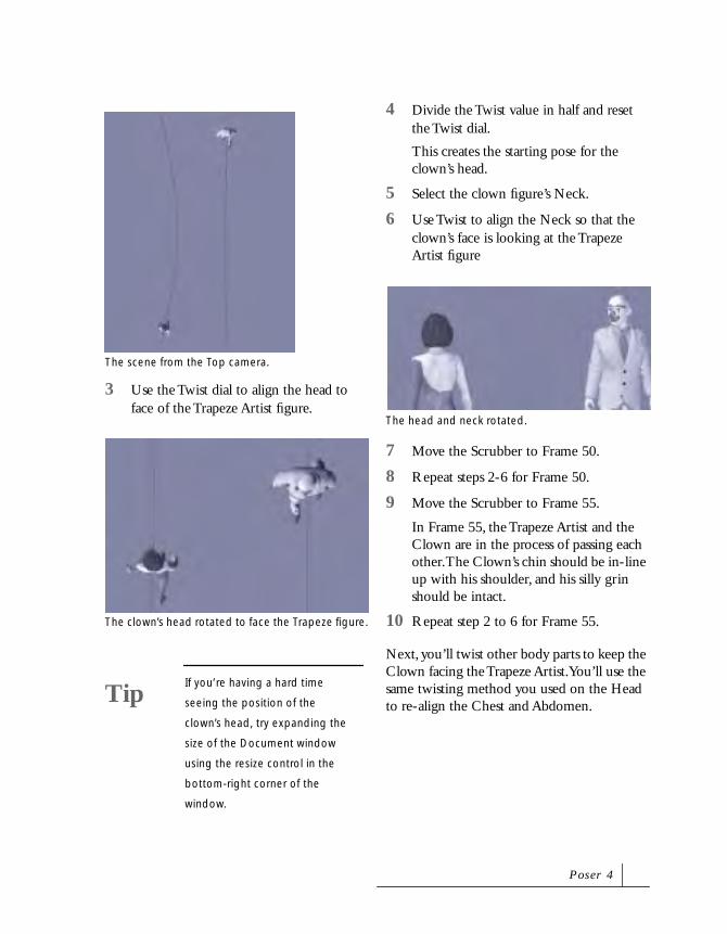
3 Use the Twist dial to align the head to face of the Trapeze Artist figure.
4 Divide the Twist value in half and reset the Twist dial.
This creates the starting pose for the clown’s head.
5 Select the clown figure’s Neck.
6 Use Twist to align the Neck so that the clown’s face is looking at the Trapeze Artist figure
7 Move the Scrubber to Frame 50.
8 Repeat steps 2-6 for Frame 50.
9 Move the Scrubber to Frame 55.
In Frame 55, the Trapeze Artist and the Clown are in the process of passing each other. The Clown’s chin should be in-line up with his shoulder, and his silly grin should be intact.
10 Repeat step 2 to 6 for Frame 55.
Next, you’ll twist other body parts to keep the Clown facing the Trapeze Artist. You’ll use the same twisting method you used on the Head to re-align the Chest and Abdomen.
The scene from the Top camera.
The clown’s head rotated to face the Trapeze figure.
TipIf you’re having a hard time
seeing the position of the
clown’s head, try expanding the
size of the Document window
using the resize control in the
bottom-right corner of the
window.
The head and neck rotated.
P o s e r 4

To align the figure’s body:
1 Click the Edit Keyframe button to open the Animation palette.
2 Select keyframes 56 through 105 of both the Clown’s Abdomen and Chest.
3 Press Delete.
4 Close the Animation palette.
5 Move the Scrubber to Frame 60.
6 Press Command/Ctrl-T to switch to the Top camera.
7 Click the Element menu and choose the Chest.
8 Use the Twist dial to align the clown’s chest so that its Head faces the Trapeze Artist.
Twist should be set to approximately -46.
9 Divide the value of the Chest’s Twist dial in half and reset Twist to the resulting number.
10 Click the Element menu and choose the Abdomen.
11 Use the Twist dial to align the abdomen so that the clown faces the Trapeze Artist.
The Edit Keyframe button.
The scene view through the Top camera.
The re-aligned chest and head.
Tu t o r i a l
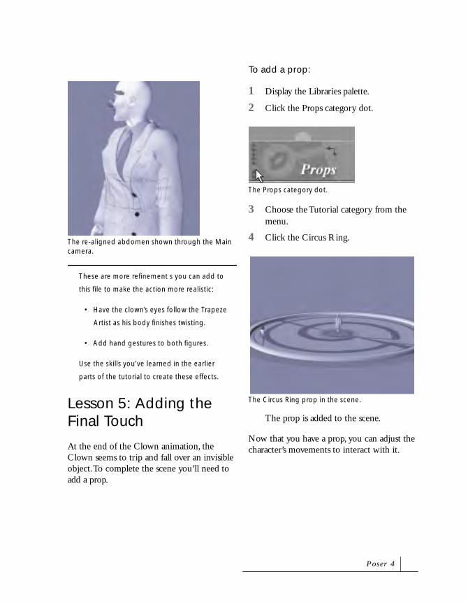
These are more refinement s you can add to
this file to make the action more realistic:
• Have the clown’s eyes follow the Trapeze
Artist as his body finishes twisting.
• Add hand gestures to both figures.
Use the skills you’ve learned in the earlier
parts of the tutorial to create these effects.
Lesson 5: Adding the Final Touch
At the end of the Clown animation, the Clown seems to trip and fall over an invisible object. To complete the scene you’ll need to add a prop.
To add a prop:
1 Display the Libraries palette.
2 Click the Props category dot.
3 Choose the Tutorial category from the menu.
4 Click the Circus Ring.
The prop is added to the scene.
Now that you have a prop, you can adjust the character’s movements to interact with it.
The re-aligned abdomen shown through the Main camera.
The Props category dot.
The Circus Ring prop in the scene.
P o s e r 4

To add an animation to your scene:
1 Click the handle at the bottom of the screen to display the Animation controls.
The center of the Animation controls, displays the current frame and the total number of frames.
2 Click the total number of frames field.
3 Enter 130 to add ten frames.
4 Click the current frame display and enter 121.
5 Click the Poses category dot in the Libraries palette.
6 Click the sub-category menu and choose Tutorial.
7 Click the Clown Flop pose.
This ten frame animation will be added to your the animation.
Lesson 6: Setting Animated Cameras and Test Rendering
In this lesson you’ll use the Dolly camera (the only free floating camera in Poser) to render the scene. You could use any camera to render, the Main, Auxiliary, Posing, and Head cameras
The total number of frames field.
The current frame field.
The Poses category dot.
The Clown Flop pose in the library.
NoteWhen you’re setting up an
animated pose like Clown Flop
to append to a work in progress,
be sure not to move the entire
Body. Adjust the Hips instead to
get the proper motion in
relation to the last pose created.
Tu t o r i a l
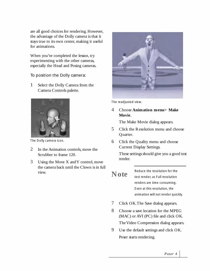
are all good choices for rendering. However, the advantage of the Dolly camera is that it stays true to its own center, making it useful for animations.
When you’ve completed the lesson, try experimenting with the other cameras, especially the Head and Posing cameras.
To position the Dolly camera:
1 Select the Dolly Camera from the Camera Controls palette.
2 In the Animation controls, move the Scrubber to frame 120.
3 Using the Move X and Y control, move the camera back until the Clown is in full view.
4 Choose Animation menu> Make Movie.
The Make Movie dialog appears.
5 Click the Resolution menu and choose Quarter.
6 Click the Quality menu and choose Current Display Settings.
These settings should give you a good test render.
7 Click OK. The Save dialog appears.
8 Choose a save location for the MPEG (MAC) or AVI (PC) file and click OK.
The Video Compression dialog appears.
9 Use the default settings and click OK.
Poser starts rendering.
The Dolly camera icon.
The readjusted view.
NoteReduce the resolution for the
test render, as Full resolution
renders are time consuming.
Even at this resolution, the
animation will not render quickly.
P o s e r 4

Lesson 7: Final Render
After one or more test renders, you’re ready to start the final rendering.
To render your final animation:
1 Choose Render menu> Current Render Settings.
2 Adjust the Current Render Settings as needed.
Enable Shadows and Anti Aliasing to produce the best results.
3 Click Render Now.
Depending on the Image Size and Computer System, the final render takes between 45 minutes to two hours.
Poser’s animation tools are its single most powerful features. Creating animation is challenging, even for the most experienced user. Patience is key to using all 3D applications, and Poser is no exception.
Tu t o r i a l


4Posing
How Posing WorksPosing is the process of bending, twisting, and pulling a figure into new and fantastic positions.
There are two aspects of a pose: how the body parts twist and bend and the position of the body in the studio. The Editing Tools let you move both body parts and entire bodies simply by clicking and dragging.
Since you’re working in three-dimensional space, you can pose your figure in almost any position. The only limits are specific range of motion limits placed on individual body parts, to keep poses realistic. For example, in the human figure, you can’t twist the head 360°.
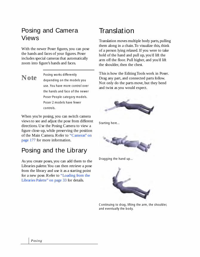
Posing and Camera Views
With the newer Poser figures, you can pose the hands and faces of your figures. Poser includes special cameras that automatically zoom into figure’s hands and faces.
When you’re posing, you can switch camera views to see and adjust the pose from different directions. Use the Posing Camera to view a figure close-up, while preserving the position of the Main Camera. Refer to “Cameras” on page 177 for more information.
Posing and the Library
As you create poses, you can add them to the Libraries palette. You can then retrieve a pose from the library and use it as a starting point for a new pose. Refer to “Loading from the Libraries Palette” on page 33 for details.
TranslationTranslation moves multiple body parts, pulling them along in a chain. To visualize this, think of a person lying relaxed. If you were to take hold of the hand and pull up, you’d lift the arm off the floor. Pull higher, and you’d lift the shoulder, then the chest.
This is how the Editing Tools work in Poser. Drag any part, and connected parts follow. Not only do the parts move, but they bend and twist as you would expect.
NotePosing works differently
depending on the models you
use. You have more control over
the hands and face of the newer
Poser People category models.
Poser 2 models have fewer
controls.
Starting here...
Dragging the hand up...
Continuing to drag, lifting the arm, the shoulder, and eventually the body.
P o s i n g
Inverse KinematicsPoser’s Inverse Kinematics (IK) features help you achieve realistic poses and natural motion in animations. The term may sound intimidating, but IK is easy to use and understand.
The effects of IK are most apparent when using the Editing Tools. Translate the hip—the legs bend to accommodate the new hip position without changing the foot position. Translate a foot—the hips and other leg stay fixed in position.
The behavior of the arms under IK is similar. If you place a figure’s hands against an imaginary wall, moving the hip toward the wall causes the arms to bend. The arms bend while the hands remain fixed in position.
If you enable IK on a pose created with IK turned off, the rules of IK can force the pose to change.
Understanding IK
Kinematics is the study of motion, velocity, rotation, and position. In terms of jointed structures, like an arm or leg, forward kinematics can be used to calculate how actions at the root of the structure determine the position and rotation of those at the end. For example, by raising your arm, the hand at the end of it is automatically translated to a new position and rotation. If you know the angle the arm raises, you can calculate the new position of the hand.
IK uses the same kind of dependency, but in reverse. The extremity moves, and IK determines how the objects joined to it (closer to the root) must respond to support the new placement. For example, if someone was to grab your hand and push, your arm would automatically bend at the elbow, while your shoulder would stay fixed in position.
Poser supports IK for the legs and arms. When IK is turned on, you can translate the hands and feet and achieve appropriate arm and leg positions automatically.
When IK is turned on for the arms or legs, the hands and feet have targets to indicate the end of the chain. When the hands or feet are moved, the target moves—it is reset to a new position. When you move any other body part, the targets remain fixed and the arms and legs reach for their targets. Once the target is reached, the end of the chain is fixed, and the other parts must bend to accommodate the hand or foot position. For example, a foot reaches its target and the knee bends.
P o s e r 4

To work effectively with IK, note the following:
• IK is enabled when you use the Editing Tools.
• The Rotate, Translate, and Twist tools may not behave as expected on some body parts. For example, you cannot easily rotate or translate a thigh or shin when IK is enabled—the foot’s position takes precedence.
This corresponds to the natural behavior of your limbs. When you stand, your feet and legs support your body weight, so you cannot arbitrarily move or rotate them. This consideration applies to using Editing Tools and Parameter Dials.
• You cannot use both the Chain Break tool and IK on the same limb.
Turning IK On or Off
Inverse Kinematics can be set for the legs and arms of any figure. For a new figure, IK is enabled for the legs, but not the arms. For most artists, this setting offers the most useful way to work. You can enable IK for the arms or disable it for either or both legs.
To change the IK setting for the current figure:
• Choose Figure menu> Use Inverse Kinematics> the limb you want to change. IK is turned on when the menu item for that limb has a check beside it.
Lift the foot and the leg bends naturally.
Translate the hips down and the knees bend.
P o s i n g

Limiting Motion
The Use Limits option keeps body parts within a natural range of motion. This feature does not apply to parts affected by IK.
What is considered natural differs among individuals. Poser’s default limits are a rough guideline, and may not look right to you. You can customize the range of motion by setting the Use Limits maximum and minimum.
In some cases, Use Limits may prevent you from posing a part where you want it. Keep this in mind when you modify Use Limits.
To turn Use Limits on or off:
• Choose Figure menu> Use Limits. Use Limits is on when the menu item has a check beside it.
To change the range of motion allowed by Use Limits:
1 Select the body part whose range you want to adjust.
2 Double-click the Parameter Dial for the motion you want to adjust.
3 In the dialog, change the Max and Min values.When you are done, click OK.
Posing Body PartsLike the human body, Poser figures are made of body parts connected by joints. You manipulate the separate body parts to pose a figure. Because body parts are independent,
each is considered an object or element. This is also true for the animal models. No matter how many legs an animal has, each leg is connected by joints which bend and extend.
Selecting Parts
You can select a part to pose in one of the following ways:
• Click on the part in the studio.
• Use the Current Element pop-up beneath the Document window.
• Select the part from the Hierarchy Editor. For details on, refer to “Selecting Objects” on page 292.
Posing a FigureThe easiest way to pose your figure is to choose one of the Editing Tools, select a body part, and drag the mouse to move the part. How the part moves depends on which part it is, the tool you use, and the direction you drag. It also depends on whether Inverse Kinematics (IK) is enabled. IK is a special
An example of a selected body part.
P o s e r 4
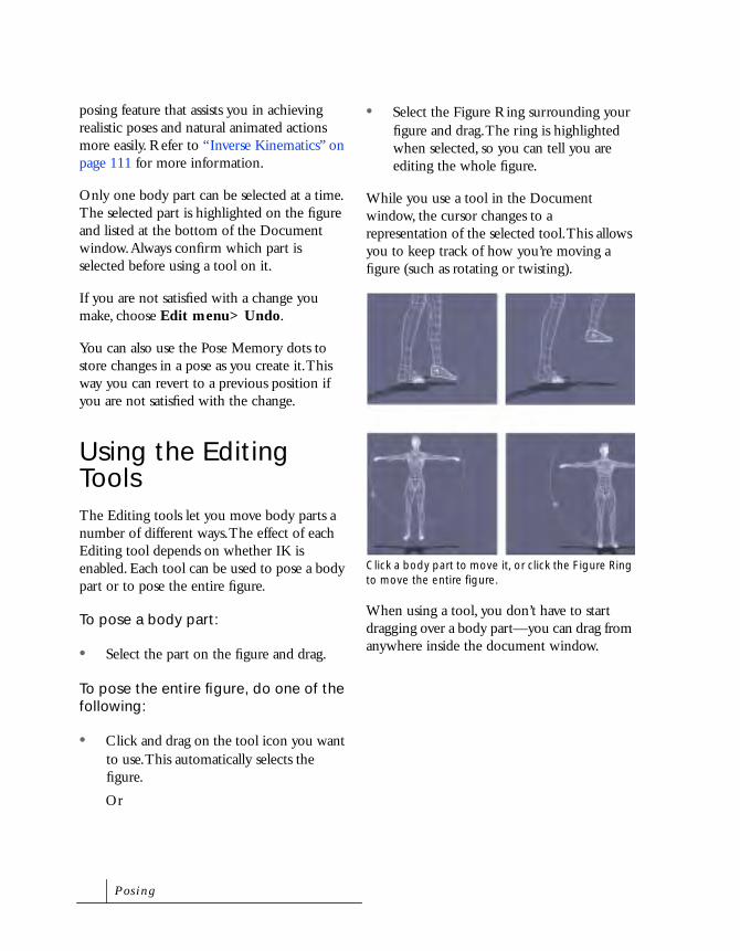
posing feature that assists you in achieving realistic poses and natural animated actions more easily. Refer to “Inverse Kinematics” on page 111 for more information.
Only one body part can be selected at a time. The selected part is highlighted on the figure and listed at the bottom of the Document window. Always confirm which part is selected before using a tool on it.
If you are not satisfied with a change you make, choose Edit menu> Undo.
You can also use the Pose Memory dots to store changes in a pose as you create it. This way you can revert to a previous position if you are not satisfied with the change.
Using the Editing ToolsThe Editing tools let you move body parts a number of different ways. The effect of each Editing tool depends on whether IK is enabled. Each tool can be used to pose a body part or to pose the entire figure.
To pose a body part:
• Select the part on the figure and drag.
To pose the entire figure, do one of the following:
• Click and drag on the tool icon you want to use. This automatically selects the figure.
Or
• Select the Figure Ring surrounding your figure and drag. The ring is highlighted when selected, so you can tell you are editing the whole figure.
While you use a tool in the Document window, the cursor changes to a representation of the selected tool. This allows you to keep track of how you’re moving a figure (such as rotating or twisting).
When using a tool, you don’t have to start dragging over a body part—you can drag from anywhere inside the document window.
Click a body part to move it, or click the Figure Ring to move the entire figure.
P o s i n g

Rotate Tool
The Rotate tool bends a body part at its joint. Click the Figure Ring to rotate the entire figure. Rotate works in three dimensions, so you can make a lot of progress with only a few moves.
Rotating a Body Part
The direction you drag determines how the part moves in each of the three dimensions.
• Drag perpendicular to the part to move it side-to-side or up and down.
• Drag parallel to the part to move it toward or away from you.
Drag perpendicular to the arm to move the arm down to the side.
After moving the arm down toward the side.
Drag parallel along the arm to move the arm around to the front.
P o s e r 4

Rotating is easier when you view the bending part from the side. For example, in the discus thrower shown below, the left hand is better viewed from the side than from the front.
For this reason, you’ll probably switch cameras several times as you pose different parts of a figure. Refer to “Cameras” on page 177 for details on using cameras.
Rotating the Entire Figure
When you drag the Rotate tool, the figure turns in three dimensions.
It takes a little imagination to understand how a two-dimensional mouse rotates a figure in three dimensions. Imagine a figure enclosed in a glass trackball. Now use the mouse to drag the front of the trackball to rotate it in the direction you want to turn the figure. The location on the trackball where you begin dragging makes a big difference in the direction the figure turns.After the arm is moved around to the front.
Using different camera views helps you to pose a figure more easily.
Original position.
P o s i n g

Rotation on the X Axis
Drag down from the center of the window to rotate the figure face down.
Rotation on the Y Axis
Drag left or right from the center of the window to turn a figure side-to-side.
Rotation on the Z Axis
Drag in a circle from a corner of the window to turn a figure on its side.
Rotation on Several Axes
Drag at an angle to compound rotation.
Drag down to rotate on the x axis.
Drag left or right to rotate on the y axis.
Drag in an arc to rotate on the z axis.
Drag at an angle to rotate on several axes.
P o s e r 4

Twist Tool
Twist rotates a body part along its own axis. You can twist the entire figure by selecting the Twist tool and dragging. The entire figure twists around its own axis.
Twisting a Body Part
Drag laterally when twisting a specific body part, regardless of the part’s angle.
Many of the human body’s joints don't allow for much twist. The forearm can twist nearly 180°, but the hand can hardly twist at all. Keep this in mind as you pose the figure.
The axis of the head, neck, and trunk is in line with the spine. The axis of a part in an arm or leg is in line with its length.
Twist the forearm to turn the palm up.
Twist the head to turn it to the side.
P o s i n g

Twisting the Entire Figure
When you drag the Twist tool, the figure rotates around its own axis. Drag laterally, regardless of which way the figure is leaning.
If the figure is lying down, the Twist tool rolls it over, from its stomach to its back.
Translate/Pull Tool
Translate/Pull moves the selected part or figure vertically or laterally (in the x and y dimensions), depending on how you drag.
Using Translate/Pull on the Entire Figure
When you drag the Translate/Pull tool, the figure moves laterally or vertically (in the x and y dimensions) in relation to the camera.
Drag in the direction you want to move the figure.
If you’ve rotated a figure to the edge of the window, you may want to move it back to the center. You may also move a figure if you are working with more than one, and want to place the figures relative to each other.
When a figure is standing, the Twist tool spins it around.
Translating moves a figure around the studio.
P o s e r 4

Translate In/Out Tool
Translate In/Out tool moves the selected part or figure in the z dimension—toward or away from the camera.
Using Translate In/Out on a Body Part
When you translate a body part, drag down to pull the part toward you. Drag up to push the part away.
Hold down the Command/Ctrl key to toggle between the Translate/Pull and Translate In/Out tools.
Using Translate In/Out on the Entire Figure
When you drag the Translate In/Out tool, the figure moves toward or away from the camera (in the z dimension). Drag down to move the figure toward you. Drag up to move it away.
Moving a figure toward you makes it appear larger in the window and vice-versa.
Chain Break Tool
A chain break placed on a body part ends the chain of parts affected by the Translate tools.
Use chain breaks on different body parts to modify translation effects. For example, to prevent the chest from moving, use the chain break on it. Now, if you translate the hand, only the forearm, shoulder, and clavicle are affected.
To add a chain break:
• Choose the Chain Break tool and click on the part where you want the chain Translate In/Out moves a figure toward or away
from the camera.
Chain Breaks are shown on a figure.
NoteThis feature is only available for
limbs not using Inverse
Kinematics.
P o s i n g
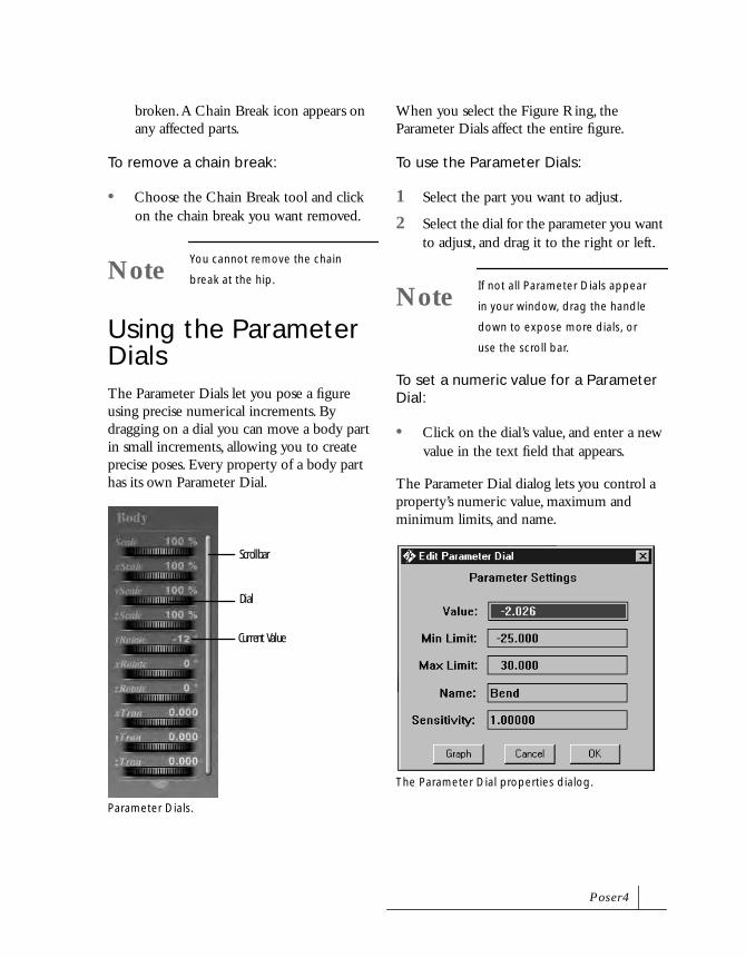
broken. A Chain Break icon appears on any affected parts.
To remove a chain break:
• Choose the Chain Break tool and click on the chain break you want removed.
Using the Parameter DialsThe Parameter Dials let you pose a figure using precise numerical increments. By dragging on a dial you can move a body part in small increments, allowing you to create precise poses. Every property of a body part has its own Parameter Dial.
When you select the Figure Ring, the Parameter Dials affect the entire figure.
To use the Parameter Dials:
1 Select the part you want to adjust.
2 Select the dial for the parameter you want to adjust, and drag it to the right or left.
To set a numeric value for a Parameter Dial:
• Click on the dial’s value, and enter a new value in the text field that appears.
The Parameter Dial dialog lets you control a property’s numeric value, maximum and minimum limits, and name.
NoteYou cannot remove the chain
break at the hip.
Parameter Dials.
Scrollbar
Dial
Current Value
NoteIf not all Parameter Dials appear
in your window, drag the handle
down to expose more dials, or
use the scroll bar.
The Parameter Dial properties dialog.
P o s e r 4

To set a Parameter Dial’s properties:
1 Double-click a Parameter Dial. A dialog appears.
2 Set any of the following options:
• Value: to change the property’s numeric value
• Min/Max Limit: modify the property’s Use Limits.
• Name: create a new name for the property.
• Sensitivity: modify the sensitivity of a parameter’s dialing habits. The lower the sensitivity value, the less movement is allowed in its element.
• Graph: click this button to modify the standard animation graph palette. For details on this palette, refer to “Editing Keyframe Interpolation” on page 225.
3 Click OK to close the dialog.
Default Parameter Dial Settings
Each body part’s Parameter Dial has a default value that defines its original state. As you work with Parameter Dials, you may wish to go back to the default, or memorized, setting.
To reset a Parameter Dial’s default values:
• Option/Alt-click the dial.
1 To change a Parameter Dial’s memorized value:
2 Set the dial to the value you want to be memorized.
3 Choose Edit menu> Memorize> choose a menu item.
Posing Parameters
The following Parameter Dials are available for posing. Since some properties don’t apply to certain body parts, the number of dials change as you select different parts.
Twist
Twist rotates a body part along its own axis. For example, you can use twist on the head and neck to turn the head. When you use it on the chest and abdomen, Twist manipulates the figure’s supple spine. Twist is also useful in the shoulder and forearm, where it turns the hand palm up.
Bend
Bend rotates a part on its major axis. All parts—except the shoulder and hand—bend forward and back. The shoulder and hand bend up and down.
Side-to-Side
Side-to-Side rotates the part perpendicular to its major axis. All the parts on the spine allow some side-to-side motion. The thigh has a lot of side-to-side motion, but the knee has very little.
P o s i n g

Turn
The Turn dial appears for the feet only, rotating them outward or inward. Turning both feet in makes a figure pigeon-toed.
Front-to-Back
Front-to-Back is used with the shoulders and collars. It rotates them forward or back, perpendicular to their major axis.
Posing Parameters for the Body
The following Parameter Dials are available for entire figures.
If you are working with more than one figure, remember to select the one you want to move before dragging a dial.
xRotate
xRotate rotates a figure around the x axis at the figure’s hip. Drag the dial to the right to rotate the figure face down.
yRotate
yRotate rotates a figure around the y (vertical) axis. This works like the Twist tool, except that you twist the entire figure. Drag the dial to the right to rotate a figure counter-clockwise.
xRotate, side view.
yRotate, top view.
P o s e r 4

zRotate
zRotate rotates a figure around the z axis. Drag the dial to the right to lean a figure to the right.
xTran
xTran moves a figure horizontally (in the x dimension). Drag the dial to the right to move a figure in that direction.
yTran
yTran moves a figure vertically (in the y dimension). Drag the dial to the right to move a figure up in the window.
zTran
zTran moves a figure toward or away from you (in the z dimension). Drag the dial to the right to move a figure toward you.
Symmetry
The Symmetry command allows you to copy pose characteristics from one side of the body to the other. This is a great time saver. Pose one arm or leg, then use symmetry to immediately put the other arm or leg in a matching pose.
Another form of symmetry swaps the pose characteristics of the right and left. You can swap the arms, legs or both.
zRotate, front view.Before and After Symmetry: Right to Left.
Use Symmetry: Swap Right and Left to mirror the pose.
P o s i n g

You can apply symmetry to both the arm and the leg (Left to Right or Right to Left), or just the arm or just the leg. You can also use Symmetry to straighten the torso.
To apply symmetry:
1 Choose Figure menu> Symmetry> select a symmetry option.
2 A dialog appear asking if you want to copy the joint zone’s setup also. Unless you are working with a custom figure, click No (the default). For complete details on using joint zones, refer to “Figure Joints and Blend Zones” on page 278.
Drop to Floor
You can place a figure in any position, such as a mid-air leap. There’s nothing wrong with having your figure in the air, but if a floating figure doesn’t match your plans for the image, you can bring a figure to the studio floor with the Drop to Floor command.
To drop a selected figure to the floor:
• Choose Figure menu> Drop to Floor. This brings the lowest part of the body to contact the floor.
To display the floor:
• Choose Display menu> Guides> Ground Plane.
Copying and Pasting
Poser’s Copy and Paste feature lets you copy a pose from one body part and paste it onto another, or from one figure to another.
You can even copy a pose from one type of body part to a different type of part. For example, you could copy a twisted arm and paste it onto a shin, to achieve the same
In this example, the Shoulder’s pose was copied to the Abdomen.
Here, the man’s pose was copied to the female figure.
P o s e r 4

amount of twist. However, note that all parameters from the copied body part are pasted to the new body part, so the results may not be ideal.
To copy and paste a pose to another body part:
1 Pose a body part.
2 With the body part selected, choose Edit menu> Copy, or Command/Ctrl-C.
3 Click to select the body part you want to copy the pose to. This can be a body part on the same figure, or a body part on another figure in the studio.
4 Choose Edit menu> Paste, or Command/Ctrl-V.
The pose is copied to the new body part.
When you copy a pose from one limb to its opposite, you do not achieve the mirrored position; the translated position of the copied limb equals the translated position of the pasted limb.
Element Properties
Poser offers various options for manipulating and displaying body parts. You can change their name, make them invisible, and stop them from bending.
To change a body part’s properties:
1 Select the part you want to work with.
2 Double-click the part or choose Object menu> Properties. The Properties dialog appears.
3 Set any of the following options in the Element Properties dialog:
• Name: rename the part.
• Visible: toggle the part visible or invisible. In an animation, you cannot make an element visible in one frame, but hidden in another.
• Casts Shadow: toggle shadow casting for the part.
• Bend: toggle the part bendable or not. For details, refer to “About Bending” on page 127.
• Add Morph Target: add a custom morph target to the part. For details, refer to “Adding Custom Morph Targets” on page 156.
4 Click OK to close the dialog.
The Element Properties dialog.
P o s i n g

About Bending
All body parts are separate elements, or objects. As you change their positions, Poser tries to maintain the continuity of the body as a whole. The arm should connect to the body smoothly, and so on for every transition between parts.
Poser achieves smooth transitions in any pose by bending body parts where they join. However, the bending information for the human body may not work well for a body part replaced with a prop. You can disable bending for the body part replaced by the prop. For more information on bend, refer to “Replacing a Body Part with a Prop” on page 173.
When rendering an image created with the Bend option disabled, parts may appear disjointed. This may be useful for special effects, such as creating a robotic form.
Posing HandsIn the Figures palette, models in the People sub-category have fully articulated hands; when you move a finger, its knuckle joints bend naturally.
Hands for all other models can be posed using the preset Hand positions in the Libraries palette.
The Left and Right Hand Cameras use the hand as their center of rotation, making it easier to create precise hand poses.
Use the same Editing Tools to pose a hand as you use on the rest of the body. The hand’s fingers are body parts just like an arm or leg; once you select them, you can rotate, twist, or position fingers just like any other body part.
Locking Hand Poses
After you finish posing, you can use the Lock Hand Parts option to protect the hand’s pose while you work on the rest of the figure.
To lock an articulated hand pose:
1 Click the hand you want to lock.
2 Choose Figure menu> Lock Hand Parts. The hand is locked in place. No finger parts can be selected or repositioned.
This command is only available with figures from the People sub-category.
Use the Hand Cam to easily view a figure’s hand.
P o s e r 4
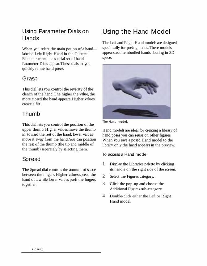
Using Parameter Dials on Hands
When you select the main potion of a hand—labeled Left/Right Hand in the Current Elements menu—a special set of hand Parameter Dials appear. These dials let you quickly refine hand poses.
Grasp
This dial lets you control the severity of the clench of the hand. The higher the value, the more closed the hand appears. Higher values create a fist.
Thumb
This dial lets you control the position of the upper thumb. Higher values move the thumb in, toward the rest of the hand; lower values move it away from the hand. You can position the rest of the thumb (the tip and middle of the thumb) separately by selecting them.
Spread
The Spread dial controls the amount of space between the fingers. Higher values spread the hand out, while lower values push the fingers together.
Using the Hand Model
The Left and Right Hand models are designed specifically for posing hands. These models appears as disembodied hands floating in 3D space.
Hand models are ideal for creating a library of hand poses you can reuse on other figures. When you save a posed Hand model to the library, only the hand appears in the preview.
To access a Hand model:
1 Display the Libraries palette by clicking its handle on the right side of the screen.
2 Select the Figures category.
3 Click the pop-up and choose the Additional Figures sub-category.
4 Double-click either the Left or Right Hand model.
The Hand model.
P o s i n g

Using Preset Hands
When you’re done posing a hand, you can save it as a preset hand pose in the Libraries palette. Hand poses are saved the same way a figure pose is saved.
To use a hand pose:
1 Click a figure to select it.
2 Display the Libraries palette by clicking its handle on the right side of the screen.
3 Click the Hands category button. If the button is not visible, move the cursor over the category dots at the top of the palette until the Hands icon appears.
4 Double-click the preview of the pose you want to use. A dialog appears asking if you want to apply the hand to the left or right hand.
5 Click either Left Hand or Right Hand button, then click OK.
Posing FacesPoser’s People figures have fully articulated faces, meaning you can position facial muscles such as mouth, eyebrows, cheeks and eyes to create different facial expressions. You’ll use the Parameter Dials to pose faces.
When you select the head, a series of face-specific Parameter Dials appears; each dial controls a different aspect of the face. When using these Parameter Dials, keep in mind that you are controlling the muscles in the face. Because an expression is made up of different muscle movements, you need to adjust several parameters to create an expression.
The Face Camera uses a figure’s face as its center of rotation, letting you view it from any angle.
NotePreset hands include Basic Hands
and Poser 2 Fig Hands. You can
only apply Basic Hands to the
People and Poser 3 Low Res sub-
categories of figures. Poser 2 Fig
Hands can only be applied to
Poser 2 figures.
NoteOnly the People sub-category of
figures have posable faces.
Use the Face Camera for posing a figure’s face.
P o s e r 4

Using the Parameter Dials
The normal range of the facial Parameter Dials is 0 to 1. This range represents the normal range of motion of the face and produces realistic expressions. Values above 1 produce an exaggerated pose, like a wide gaping mouth. Values below 0 (that is, negative values) produce the opposite effect of the parameter. For example. a negative Frown value produces a slight smile.
Mouth Parameters
These dials controls a figure’s mouth and tongue. Together the dials control most of the muscles in the lower face.
OpenLips
Controls the distance between lips. Positive values spread the lips. Negative values move them closer together.
Smile
Positive smile values raise the corners of the mouth and close the eyes slightly. Negative value produce the opposite effect.
Frown
Positive values drop the corners of the mouth. Negative values produce a slight smile.
Mouth O
When the Mouth O dial is set to 1, the lips are in position to produce the O sound. Positive values pucker the lips. Negative values stretch out the lips.
Mouth F
When the Mouth F dial is set to 1, the lips are in position to produce the F sound. Using positive values, the lower lip tucks up under the upper teeth. With negative values, the lower lip juts out.
Mouth M
When the Mouth M dial is set to 1, the lips are in position to produce the M sound. A positive value presses the lips together. A negative value spreads out the lips.
The Mouth O dial in use.
P o s i n g

Tongue T
When the Tongue T dial is set to 1, the tongue and mouth are in position to produce the T sound. Positive values press the teeth together and moves the lower lip down, opening the mouth. Negative values close the mouth and pull the lips together.
Tongue L
When the Tongue L dial is set to 1, the tongue and mouth are in position to produce the L sound. Using positive values, the mouth opens and the tip of the tongue tucks in behind the front teeth. A negative value closes the lips.
Eyebrow Parameters
This set of Parameter Dials control the position of the eyebrows and eyelids. The Eyebrow parameters control most of the muscles in the upper half of the face.
Left/Right Brow Down
Positive values lower the brow down in a straight line. Negative values curves the brow up.
Left/Right Brow Up
Positive values lift the inner brow (that is, the part of the brow closest to the nose) up. Negative values lower the inner brow, producing an angry look.
Worry Left/Right
Positive values move the inner brow up and the outer brow down. Negative values have the opposite effect.
Blink
When the Blink dial is set to 1, the eye is completely closed. At 0 the eye is completely open. Negative values produce extremely open eyes, producing a horrified look.
Posing Eyes
You can pose the eyes within a face just like any other body part; select them using the Editing Tools and position them using the Parameter Dials. Eyes also appear on the Current Elements pop-up menu.
The Tongue T dial in use.
The Worry dials in use.
P o s e r 4

Character Morphs
The following morph target Parameter Dials are available with the Character models:
Brow: a higher value pushes the eyebrows out.
BumpNose: a higher value creates a bump on the bridge of the nose
Cheeks: a higher value makes the cheekbones more pronounced.
Chin: a higher value makes a more pronounced chin.
EyeRoundness: a higher value makes the eyes more round.
FlatFace: a higher value makes the face flatter.
FlatNose: a higher value makes a flatter nose.
HeartFace: a higher value makes a more heart-shaped face.
LashLengh: a higher value makes longer eyelashes.
LipSize: a higher value increases the volume of the lips.
LongFace: a higher value makes a longer face.
PointedNose: a higher value makes a more pointed nose.
RoundFace: a higher value makes a rounder face.
RoundNose: a higher value makes a rounder nose.
SquareFace: a higher value makes a more square-shaped face.
Faces and Phonemes
A phoneme is a linguistic term for the position of the lips, teeth, and tongue as they make sounds. To produce certain letter sounds, the mouth and tongue must be in specific positions. For example, to produce the letter A sound, the mouth is open, and the tongue is behind the lower teeth. A series of phonemes strung together produce speech.
A series of examples of Phonemes.
B
I
R
P o s i n g

In Poser, you can create the appearance of phonemes to create realistic facial animations, simulating speech. This is useful when you attach sound to figure. By setting up different animation frames with different phonemes you synchronize the face to the sound.
There are several preset phonemes included in the Faces: Phonemes sub-category on the Libraries palette. You can use these presets to help you get started. Refer to “Loading from the Libraries Palette” on page 33 for more on retrieving phonemes from the Libraries palette.
Using Preset Faces
Like hands, you can save face poses into the Libraries palette. Once saved, you can easily apply a face to any number of figures. Refer to “Saving to the Libraries Palette” on page 34 for more information.
Posing AnimalsYou can pose animal models using the same techniques you use to pose a human figure. Animal models have their own set of IK settings, Bend zones, and Use Limits, so not all the parts act as you may expect. On the Horse model, for example, moving the hip joint toward the ground does not make the horse sit, as it does in the human figure.
All the same Editing Tools and Parameter Dials you use on figures also work on animal models. The Current Figure menu, at the bottom-left of the Document window, lists all the parts that make up the animal.
Posing Animal Heads
Several animal models have fully articulated heads. For example, the dog model has a mouth and ears that can be posed. Like human figures, use the Parameter Dials to pose the features on an animal model’s head.
An example of posing a dog figure.
Posing a dog’s eyes and mouth.
P o s e r 4

When you click an animal model’s head, a set of special Parameter Dials appear that control all the posable parts of the head. Each model has different morph target parameters. To find out which parameters are posable, click on the head.
Pointing Body PartsYou can aim body parts directly at other figures, body part, or props using the Point At command. You may find this feature handy, for example, to illustrate a figure following her hand with her eyes.
To point a body part directly at an object:
1 In the Current Element popup, select the element you want to point.
2 Choose Obejct menu> Point At. A scene selection dialog appears.
3 In the list of objects, click to select the figure, body part, or prop you want to point the element at, then click OK.
The element points at the object, and a Point At Parameter Dial appears for the element. You can adjust this parameter as needed. At 1, the element is pointed completely at the object. At 0, the element is not pointed at the object.
To disable the pointing of a body part:
1 In the Current Element popup, select the body part that is pointing.
2 Choose Obejct menu> Point At.
3 In the dialog that appears, click None.
Locking ObjectsYou can lock body parts or an entire figure, so that the editing tools and parameter dials don’t affect it. This feature is helpful when you want to protect a pose while you work on the rest of the figure
To lock a figure or body part:
1 Click the Current Element pop-up and choose the figure or element you want to lock.
2 Choose Object menu> Lock Actor. The actor is locked when this menu item is checked.
When a body part is locked, you can still manipulate other parts and the figure. If you lock an entire figure, you can still manipulate its parts, but the figure itself cannot be moved.
Auto Balance and PosingThe Auto Balance feature is a valuable tool for creating realistic poses. When Auto Balance is enabled, Poser calculates the mathematical “weight” for a figure and then maintains it. In the following example, there is more weight in the figure’s hip or center portion than in the upper torso.
3 As you pose a figure, Auto Balance adjusts body parts to maintain the original weight distribution. This results in more
P o s i n g
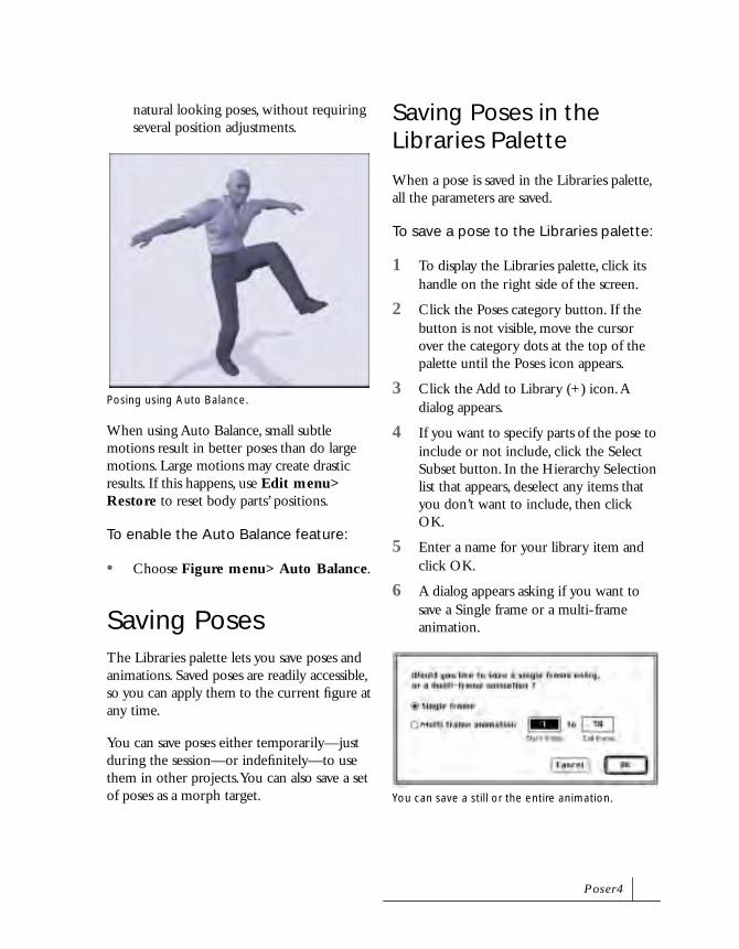
natural looking poses, without requiring several position adjustments.
When using Auto Balance, small subtle motions result in better poses than do large motions. Large motions may create drastic results. If this happens, use Edit menu> Restore to reset body parts’ positions.
To enable the Auto Balance feature:
• Choose Figure menu> Auto Balance.
Saving PosesThe Libraries palette lets you save poses and animations. Saved poses are readily accessible, so you can apply them to the current figure at any time.
You can save poses either temporarily—just during the session—or indefinitely—to use them in other projects. You can also save a set of poses as a morph target.
Saving Poses in the Libraries Palette
When a pose is saved in the Libraries palette, all the parameters are saved.
To save a pose to the Libraries palette:
1 To display the Libraries palette, click its handle on the right side of the screen.
2 Click the Poses category button. If the button is not visible, move the cursor over the category dots at the top of the palette until the Poses icon appears.
3 Click the Add to Library (+) icon. A dialog appears.
4 If you want to specify parts of the pose to include or not include, click the Select Subset button. In the Hierarchy Selection list that appears, deselect any items that you don’t want to include, then click OK.
5 Enter a name for your library item and click OK.
6 A dialog appears asking if you want to save a Single frame or a multi-frame animation.
Posing using Auto Balance.
You can save a still or the entire animation.
P o s e r 4

• If you select the Single frame option, the current pose is saved.
• If you select the Multi-frame animation option, you can specify a range of frames to save.
Choose either Single frame or Multi-frame animation from the dialog and click OK.
A rendering of the pose appears in the Libraries palette. If you saved a multi-frame animation, the number of frames appears in the Library preview.
Using the Pose Memory Dots
Use the Pose Memory Dots to store a figure’s position during a session. You can store up to nine different poses. Memory dots are saved with the file, so your figure positions are available the next time you open the file.
To save a figure position to a memory dot:
1 Set up a figure pose.
2 Click the pop-up menu above the memory dots and choose Pose Dots.
3 Click an empty memory dot. The figure position is stored into the dot you clicked.
To recall a stored position:
• Click on a memory dot. The figure moves to the stored pose.
Using Poses from the Libraries Palette
When you use a single frame pose from the Libraries palette, Poser applies it to the current frame.
When you use an animation from the library, Poser applies it to a series of frames, beginning with the current frame, and extends the full length of the applied multi-frame pose. Make sure you have enough frames ahead to accommodate the multi-frame pose. Otherwise, Poser automatically extends the length of the animation to accommodate the poses.
To load poses from the Libraries palette:
1 To display the Libraries palette, click its handle on the right side of the screen.
2 Click the Poses category button. If the button is not visible, move the cursor over the category dots at the top of the palette until the Poses icon appears.
3 Click the sub-category pop-up and choose the type of pose set you want to apply.
If you want to apply an animated pose to your figure, use the Animation Sets sub-category.
4 Double-click the preview of the pose you want to use.
Use the Pose Dots to save poses.
Empty Memory Dot
Full Memory Dot
P o s i n g

5Body Shaping
Human bodies come in all shapes and sizes. Starting with any Poser model, you can adjust its proportions to create a body of any type, from lifelike to absurd.
Poser lets you shape the body any way you like.

Poser 4 includes several features for body shaping. You can select from a library of morph targets to reshape any body part. You can create your own morph targets using the deformer tools. The Grouping tool lets you target specific sections of elements and props.
With the Scale tool, you can scale the body or its parts in one, two, or all three dimensions. Scaling all three dimensions maintains the body or object’s proportions. Scaling in one or two dimensions changes the actual shape. For example, increasing the height scale makes a figure taller. Increasing only the width and depth can make a figure stout—even rotund.
With the Taper tool, you can taper parts of the body so they make smooth transitions.
You can customize figures by replacing body parts with props you’ve imported into your scene. You can also attach a prop to a figure, such as a sword or a pair of wings.
As you create new bodies, you can save them to the Figures category in the Libraries palette. The library is the easiest way to store and retrieve body shapes.
General Characteristics
Selecting Figures from the Library
The Figures category of the Libraries palette provides many figures to work with, including various types of males, females, children, skeletons, stick figures, and animals.
Poser figures are divided into different categories of older and newer Poser models.
Models in the Poser 2 figure category are available in high resolution and low resolution versions. Low resolution models use less memory and display more quickly, while high resolution models offer better detail. High resolution models have the word “Hi” in their titles and low resolution models have “Lo”.
You can create exaggerated body types. Examples of the skeleton, stick figure and Poser 2 models.
B o dy S h a p i n g

Newer Poser models are more detailed and have fully articulated hands and faces. The Animals category also contains fully articulated animal models.
You can find the most recently Poser figures in the “People” sub-category of the Figures library. In addition to fully articulated hands and faces, they include extra morph targets, and are optimized to work with Poser’s library of clothing. The Poser People models that can change clothing begin as nudes. The People sub-category also includes Robots.
You can use older and newer Poser models together to optimize your workflow. For example, while posing, you can use a lower resolution model from a Poser 2 category to maximize the response time of your computer. Then when you’re ready to render, make a movie, or export a model, switch to a high resolution model from the People sub-category.
To change the figure type:
1 Display the Libraries palette.
2 Click the Figures category button. If the button is not available, move the cursor over the dots at the top the palette until
the Figures icon appears, then click the mouse button.
3 Click the sub-category popup menu and choose the sub-category of figures you want to use.
4 Double-click the preview of the figure you want to use.
Genitalia
The male nude model is anatomically correct. To turn display of his genitals on or off, choose Figure menu> Genitalia.
Figure Height
Poser provides several figure heights as starting points. You can modify any of these toward the body shape you want.
To set figure height:
• Choose Figure menu> Figure Height> select a height.
Using the Color Tool
You can use the Color tool to change a figure or its clothing’s color. The Color tool changes the color of the entire figure; you cannot use it on individual body parts.
Some of the People and Animal figures.
The Color tool.
P o s e r 4

To change a figure’s color:
1 Click to select the Color tool, then click the figure whose color you want to change.
2 Drag the dropper icon over the color picker that appears. Release the mouse button when you select the desired color.
Shaping Individual Body PartsShaping individual parts can significantly change the appearance of the body. Enlarge the abdomen to give the model a big belly. Stretch the head wider to give the model a broad face.
Shaping is easiest when a figure is in the default pose—with arms out, facing the camera. In this pose, you can clearly see the proportions of the separate elements and the effects of your changes.
Using the Shaping Tools
The easiest way to shape a part is to choose the Scale or Taper tool, click on the element you wish to adjust, and simply drag it. For more precise control in each dimension, use the Parameter Dials.
Scale
Drag in (toward the selected element) to reduce the scale. Drag out (away from the element) to increase the scale.
• You scale the three dimensions to varying degrees, depending on how you drag. Drag laterally to scale width and depth (x and z dimensions). Drag vertically to scale height (y dimension).
• To scale proportionally in all three dimensions, hold down the Shift key as you drag.
If the result is not what you expected, choose Edit menu> Undo.
For more precise control of the scale in each dimension, use the Parameter Dials.
You can animate the scaling of a body or body part. For details on animating, refer to “Creating Animations” on page 209.
Shaping an individual body part.
B o dy S h a p i n g
Taper
Taper adjusts the scale of one end of an element only—the other end does not change. Taper affects the end of the element that is distant from the center of the body.
Drag to the right to increase the taper. Increasing the taper shrinks the end of the element farther from the center of the body. Drag to the left to decrease the taper. This “flares” the end of the element.
Using the Parameter Dials
When you click a body part, the Parameter Dials change to display the appropriate scaling controls.
Taper
Taper adjusts the scale of one end of an element only—the other end does not change. Drag to the right to increase taper. The end of the element farther from the center of the body shrinks. Drag to the left to decrease the taper.
Scale
Scale adjusts all three dimensions proportionally. Drag the dial to the right to increase the scale.
xScale
xScale adjusts the width scale (x dimension). Drag the dial to the right to increase the scale in this dimension.
yScale
yScale adjusts the height scale (y dimension). Drag the dial to the right to increase the scale in this dimension.
zScale
zScale adjusts the depth scale (z dimension). Drag the dial to the right to increase the scale in this dimension.
Breast Size
The female model’s chest includes the BRLarge and BRSmall Parameter Dials for changing the breast size. Drag the BRLarge dial to the right to increase breast size. Drag the BRSmall dial to the right to decrease breast size.
Symmetry
You can save a lot of time and effort with the Symmetry command. When you shape an arm or leg, you can use Symmetry to give the other side the exact same proportions.
You can apply symmetry to both an arm and leg (Left to Right or Right to Left), or just an arm or leg. You can also use Symmetry to straighten the torso.
P o s e r 4

To apply symmetry:
1 Choose Figure menu> Symmetry> select an option.
2 A dialog appear asking if you want to copy the joint zone’s setup also. Unless you are working with a custom figure, click No (the default). For complete details on using joint zones, refer to “Figure Joints and Blend Zones” on page 278.
Scaling the Body as a WholeScaling the body simply changes its size. To scale the figure, select the Scale tool, select the Figure Ring for the appropriate figure, and drag in the Document window.
For details on the Scale tool, refer to “Scale” on page 140.
Body Size and Uniform Scaling
A figure’s size is significant only in relation to other figures or objects in the scene. If you are posing a single figure, uniform scaling of the body is not necessary. Instead, to make a single figure larger or smaller in the window, scale the camera.
If you are working with two or more figures and you want to make a figure appear to be in the distance, use the Translate In/Out tool to move it back in the studio space.
To make a figure a certain size for a final rendering, you can set the Rendering Options to render at a specific resolution. For details on rendering, refer to “Setting Up a Render” on page 260.
Using Parameter Dials
The Parameter Dials are particularly useful for body shaping. The values show the scale in that dimension as a percentage. The normal scale of a Poser model is 100%.
Scale
Scale adjusts all three dimensions proportionally. Drag the dial to the right to increase the scale.
xScale
xScale adjusts a figure’s width (x dimension).Scaling the entire body using the Figure Ring.
B o dy S h a p i n g
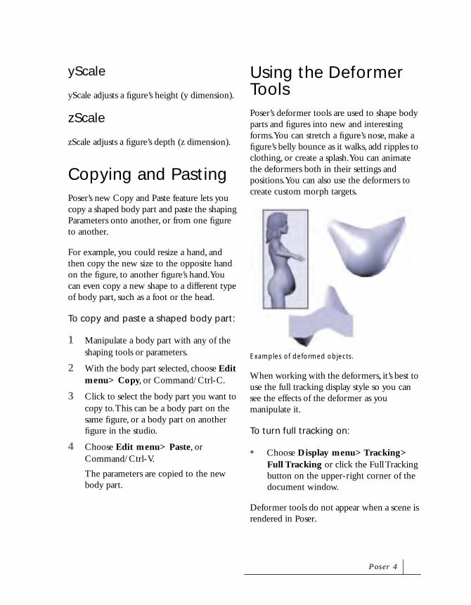
yScale
yScale adjusts a figure’s height (y dimension).
zScale
zScale adjusts a figure’s depth (z dimension).
Copying and PastingPoser’s new Copy and Paste feature lets you copy a shaped body part and paste the shaping Parameters onto another, or from one figure to another.
For example, you could resize a hand, and then copy the new size to the opposite hand on the figure, to another figure’s hand. You can even copy a new shape to a different type of body part, such as a foot or the head.
To copy and paste a shaped body part:
1 Manipulate a body part with any of the shaping tools or parameters.
2 With the body part selected, choose Edit menu> Copy, or Command/Ctrl-C.
3 Click to select the body part you want to copy to. This can be a body part on the same figure, or a body part on another figure in the studio.
4 Choose Edit menu> Paste, or Command/Ctrl-V.
The parameters are copied to the new body part.
Using the Deformer ToolsPoser’s deformer tools are used to shape body parts and figures into new and interesting forms. You can stretch a figure’s nose, make a figure’s belly bounce as it walks, add ripples to clothing, or create a splash. You can animate the deformers both in their settings and positions. You can also use the deformers to create custom morph targets.
When working with the deformers, it’s best to use the full tracking display style so you can see the effects of the deformer as you manipulate it.
To turn full tracking on:
• Choose Display menu> Tracking> Full Tracking or click the Full Tracking button on the upper-right corner of the document window.
Deformer tools do not appear when a scene is rendered in Poser.
Examples of deformed objects.
P o s e r 4

The Magnet Deformer
The Magnet deformer distorts an object by creating a virtual magnet which stretches it. The Rotate, Twist, Translate, and Scale tools can be used on the Magnet deformer, as well as several specialized Parameter Dials.
To create a Magnet deformer:
1 Select the object you want to deform.
2 Choose Object menu> Create Magnet.
When you create a magnet, three Magnet objects, which together create the deformer, are added to your scene.
• The Magnet object defines the behavior of the actual magnet.
• The Magnet Base defines the zero point of the area to be deformed. When you move the Magnet Base, the Magnet object moves with it.
• The Magnet Zone defines the area to be deformed. You can move and shape the Magnet Zone to fit your needs.
Using Editing Tools with Magnets
You can use the same tools you use for posing to position the magnet objects.
To edit a magnet object:
1 Select the magnet object from the Current Element popup.
2 Select the editing tool you want to use.
For all of these tools, when you move the Magnet Base, the Magnet object moves along with it.
The editing tools that can be used on Magnet object are:
• Rotate rotates a Magnet object around its axis in three dimensions.
• Twist rotates a Magnet object along its own axis.
• Translate/Pull moves the Magnet object horizontally or vertically (in the x and y dimensions), depending on how you drag.
• Translate In/Out moves the Magnet object in or out from the center of the studio.
A sphere deformed by the Magnet.
The three parts of the Magnet deformer.
Magnet object
Magnet Base
Magnet Zone
B o dy S h a p i n g

• Scale increases or decreases the size of the Magnet object.
Using Parameter Dials with Magnets
When a Magnet object is selected, you can use the Parameter Dials to precisely control a it’s position and orientation:
• Scale adjusts all three dimensions proportionally. Drag the dial to the right to increase the scale.
• xScale adjusts the width scale (x dimension). Drag the dial to the right to increase the scale in this dimension.
• yScale adjusts the height scale (y dimension). Drag the dial to the right to increase the scale in this dimension.
• zScale adjusts the depth scale (z dimension). Drag the dial to the right to increase the scale in this dimension.
• xRotate rotates the Magnet object around the x axis.
• yRotate rotates the Magnet object around the y axis.
• zRotate rotates the Magnet object around the z axis.
• xTran moves the Magnet object in the x dimension.
• yTran moves the Magnet object in the y dimension.
• zTran moves the Magnet object in the z dimension.
Magnet Properties
Just like body parts, you can control the properties of the Magnet objects.
To edit a Magnet object’s properties:
1 Choose the Magnet object from the Current Element popup.
2 Choose Object menu> Properties.
The Properties dialog appears.
The Properties dialogs differ depending on which Magnet object is selected.
Magnet Object Properties
The options in the Magnet Properties dialog are:
• Name: rename the Magnet object. This option is helpful when you are working with several magnets.
• Visible: toggle the Magnet visible or invisible.
NotexScale, yScale, and zScale are not
used with the Magnet Base
object.
Magnet object properties.
P o s e r 4

• Add Element to deform: add another element to be affected by the magnet. If you click this button, select an element in the Hierarchy list that appears, then click OK.
Magnet Base Properties
The options in the Magnet Base Properties dialog are:
• Name: rename the Magnet Base object.
• Visible: toggle the Magnet Base visible or invisible.
• Display Origin: display the Magnet Base’s axis. This feature is useful because the Magnet object translates on the Magnet Base’s axes, not the ground floor axes. So for example, if you use a Parameter Dial to move the Magnet along the y axis, it moves along the base’s y axis, not the studio’s y axis.
Magnet Zone Properties
The options in the Magnet Zone Properties dialog are:
• Name: rename the Magnet Zone object.
• Visible: toggle the Magnet Zone visible or invisible.
• Edit Falloff Graph: edit the Magnet Zone’s falloff (the area where the deforming ends or “falls off ”). Click this button, then edit the graph that appears.
• Set Parent: set a parent object for the Magnet Zone. Click this button, select an element in the Hierarchy list that appears, and click OK.
• Group: deform a grouped part of the selected element. Enable the checkbox, then select one or more groups from the
NoteIn order for this feature to work,
the added element must be in the
Magnet Zone, or it won’t be
deformed. You can move or scale
the Magnet Zone object to bring
the element into the zone.
Magnet Base properties dialog
Magnet Zone properties dialog
B o dy S h a p i n g

popup. A group is selected when a check appears next to it.
Locking Magnets
The Lock feature can be especially helpful for the Magnet Zone objects. Once you have a zone carefully positioned to get the effect you want, you can lock it so that it isn’t accidentally moved. For details, refer to “Locking Figures and Body Parts” on page 159.
Tutorial: Using the Magnet Deformer
This short tutorial demonstrates how easy it is to use the Magnet deformer. For a simple demonstration, we’ll use a magnet on an empty ground plane.
To use the magnet deformer:
1 To remove any figures from the scene, select the figure in the Current Figure popup, then choose Figure menu> Delete Figure.
2 Choose Display menu> Guides> Ground Plane, then click the ground plane to select it.
3 If the Display Shadows control is on, turn it off by choosing Display menu> Ground Shadows.
4 Choose Object menu> Create Magnet. The Magnet, Magnet Base, and Magnet Zone objects appear.
The Magnet object scales to a size bigger than the object it has been created for, so in this case it is quite large. For a smaller body part or prop, the magnet would not appear so large.
5 Now you’ll probably want to zoom out a little. Drag the X and Z camera control up until the entire ground plane is showing in your Document window.
6 Click the Translate/Pull tool, then click the Magnet object.
TipTo get an optimal 3D view of the
magnet zone, change its display
style to Wireframe. Select the
Magnet Zone, select Element
Styles from the Document Display
Style popup, then click the
Wireframe icon.
The X and Z camera control.
P o s e r 4

7 Drag the magnet up, down, and side-to-side. The ground plane follows the magnet around.
8 Click the Rotate tool, and rotate the Magnet object around. The ground plane rotates around the center of the Magnet Base object.
9 In the Current Element popup, choose Mag Zone 1 to select the Magnet Zone object.
10 Drag the Scale Parameter Dial for the Magnet Zone and scale the zone to about 50%. Now only the portion of the ground plane within the magnet zone is deformed. Experiment with the editing tools and Parameter Dials on the zone.
For example, translate the zone to the right to move the area being deformed.
11 With the Magnet Zone still selected, choose Edit menu> Restore> Element. The zone returns to its original size and shape.
12 Choose Mag Base 1 from the Current Element popup.
13 Using the Editing tools or Parameter Dials, experiment with scaling, rotating, and translating the Magnet Base object.
Translating the Magnet object.
Rotating the Magnet object.
Translating the Magnet Zone object.
Rotating the Magnet Base object.
B o dy S h a p i n g

The Wave Deformer
The Wave deformer distorts an object by creating a wave path for it. The Rotate, Twist, Translate, and Scale tools can be used on the Wave deformer, as well as several specialized Parameter Dials.
To create a Wave deformer:
1 Select the object you want to deform.
2 Choose Object menu> Create Wave.
When you create a Wave deformer, two wave objects, which together create the deformer, are added to your scene:
• The Wave object defines the behavior of the actual wave.
• The Wave Zone defines the area to be deformed.
Using Editing Tools with Waves
You can use the same tools you use for posing to position the wave objects.
To edit a wave object:
1 Select the wave object from the Current Element popup.
2 Select the editing tool you want to use.
The editing tools that can be used on Wave objects are:
• Rotate rotates a wave object around its axis in three dimensions.
• Twist rotates a wave object along its own axis. Twist has no effect on the radial wave.
• Translate/Pull moves a wave object horizontally or vertically (in the x and y dimensions), depending on how you drag.
A cube distorted by the Wave deformer.
The two parts of the Wave deformer.
Wave object
Wave Zone
P o s e r 4

• Translate In/Out moves a wave object in or out from the center of the studio.
• Scale increases or decreases the size of a wave object.
Using Parameter Dials with Waves
When a wave object is selected, you can use the Parameter Dials to precisely control a wave’s position and behavior.
The Parameter Dials available for both the Wave and Wave Zone objects are:
• Scale adjusts all three dimensions proportionally. Drag the dial to the right to increase the size of the wave object.
• xRotate rotates the wave object around the x axis. For this parameter to affect the Wave Zone, the zone must be disproportionately scaled (not perfectly round).
• yRotate rotates the wave object around the y axis. For this parameter to affect the Wave Zone, the zone must be disproportionately scaled (not perfectly round).
• zRotate rotates the wave object around the z axis. For this parameter to affect the Wave Zone, the zone must be disproportionately scaled (not perfectly round).
• xTran moves the wave object in the x dimension.
• yTran moves the wave object in the y dimension.
• zTran moves the wave object in the z dimension.
The Parameter Dials available only for the Wave object are:
• Phase defines the position of the wave in the infinite time. Use this dial when you are animating waves.
• Amplitude defines the wave’s height.
• Wavelength defines the distance from one wave crest to another.
• Stretch defines the amount of stretch for each wave.
• Amp Noise defines the randomness or “noise” of the wave pattern’s amplitude.
• Freq Noise defines the randomness or “noise” of the wave pattern’s frequency.
• Sinusoidal defines the size of the sine wave pattern.
• Square defines the shape of the wave pattern. Drag the dial to the right to create square-shaped waves.
• Triangular defines the shape of the wave pattern. Drag the dial to the right to create triangle-shaped waves.
• Turbulence defines the roughness of a wave pattern. Drag the dial to the right to create jagged, or turbulent waves. Drag the dial to the left to create a smooth wave patter.
• Offset controls whether the wave pattern is above, below, or across the wave’s origin. Drag the dial to the right to bring the wave pattern above the origin. This control is handy, for example, when you want to keep clothing from deforming into a figure.
B o dy S h a p i n g

The Parameter Dials available only for the Wave Zone object are:
• xScale adjusts the width scale (x dimension). Drag the dial to the right to increase the scale in this dimension.
• yScale adjusts the height scale (y dimension). Drag the dial to the right to increase the scale in this dimension.
• zScale adjusts the depth scale (z dimension). Drag the dial to the right to increase the scale in this dimension.
Wave Properties
Just like body parts, you can control the properties of the wave objects.
To edit a wave object’s properties:
1 Choose the wave object from the Current Element popup.
2 Choose Object menu> Properties.
The Properties dialog appears.
The Properties dialogs differ depending on which wave object you select.
Wave Object Properties
The options in the Wave Properties dialog are:
• Name: rename the Wave object. This option is helpful when you are working with several waves.
• Visible: toggle the Wave object visible or invisible.
• Add Element to deform: add another element to be affected by the wave. If you click this button, select an element in the Hierarchy list that appears, then click OK.
Wave object properties dialog.
NoteIn order for this feature to work,
the added element must be in
the Wave Zone, or it won’t be
deformed. You can move or scale
the Wave Zone object to bring
the element into the zone.
P o s e r 4

Wave Zone Properties
The options in the Wave Zone Properties dialog are:
• Name: rename the Wave Zone.
• Visible: toggle the Wave Zone visible or invisible.
• Edit Falloff Graph: edit the Wave Zone’s falloff (the area where the deforming ends or “falls off ”), Click this button, then edit the graph that appears.
• Set Parent: set a parent object for the Wave Zone. Click this button, select an element in the Hierarchy list that appears, and click OK.
• Group: deform a grouped part of the selected element. Enable the checkbox, then select one or more groups from the popup. A group is selected when a check appears next to it.
Using Morph TargetsA morph target is a custom Parameter that is added to a body part so you can gradually reshape it. Poser includes several built-in morph targets in its library, and you can build your own.
With morph targets, you can easily resize and reshape body parts. Just like any other motion, you can animate your morphs.
For an example of how morph targets you can use, take a look at the Head parameters of a Poser People figure. All the facial parameters, such as Mouth and Tongue settings, were created using morph targets.
Wave Zone properties dialog.
Use a morph target to make transitional changes in a figure’s geometry.
B o dy S h a p i n g

Using Morph Targets to Add Ethnicity
Poser now includes morph targets which allow you to easily add ethnic traits to your figures.
To use an ethnic morph target:
1 Display the Libraries palette.
2 Click the Figures category button. If the button is not available, move the cursor over the dots at the top the palette until the Figures icon appears, then click the mouse button.
3 Click the sub-category popup menu and choose the Characters sub-category.
4 Double-click the preview of the figure you want to use.
The new figure contains an ethnicity morph target Parameter Dial.
If you want to customize your own figure, the following morph target Parameter Dials are available with the Character models:
Brow: a higher value pushes the eyebrows out.
BumpNose: a higher value creates a bump on the bridge of the nose
Cheeks: a higher value makes the cheekbones more pronounced.
Chin: a higher value makes a more pronounced chin.
EyeRoundness: a higher value makes the eyes more round.
FlatFace: a higher value makes the face flatter.
FlatNose: a higher value makes a flatter nose.
HeartFace: a higher value makes a more heart-shaped face.
LashLengh: a higher value makes longer eyelashes.
LipSize: a higher value increases the volume of the lips.
LongFace: a higher value makes a longer face.
PointedNose: a higher value makes a more pointed nose.
RoundFace: a higher value makes a rounder face.
RoundNose: a higher value makes a rounder nose.
SquareFace: a higher value makes a more square-shaped face.
Using morph targets to change a figure’s ethnicity.
P o s e r 4

Using the Superhero Morph Target
Poser includes a full figure morph target in which the entire figure is morphed in various body parts simultaneously to form a superhero character.
The full figure morph target is the Superhero Parameter Dial on the body. Drag to the right to move the figure into the morph.
Creating Custom Morph Targets
You can create your own morph targets in Poser as well as other applications. In this section, you’ll learn how to create morph targets in Poser. For details on creating morph targets in other applications, refer to “Creating Custom Morph Targets” on page 272.
You can use one or a combination of the deformers and morph channels (such as the Worry dials on the articulated faces) to create custom morph targets. When you create a morph target on an element, a new Parameter Dial is added.
To create a morph target in Poser:
1 Shape an element using any available morph channels or deformers.
When you shape multiple elements on a body part and then create a morph target, all the changes in shape are included.
2 With the body part selected in the Current Element popup, choose Object menu> Spawn Morph Target.
3 In the dialog that appears, enter a name for the morph target. The target appears in the list of Parameter Dials.
4 Drag the dial to the right to reshape the element toward the morph. Drag the dial to the left to reshape it away from the morph.
5 A value of 0.0 for this dial is the original object, while a value of 1.0 changes the body part to the morph target. A value of 0.5 is halfway between the original object and the morph target. A negative value inverts the vertices.
TipIf you used deformers on the
element and don’t plan to use
them anymore, you may delete
them now.
NoteIf you left the deformers and
morph channels on the element,
the morph target will add on top
of them, so the effects will seem
doubled. To restore the body
part, choose Edit menu>
Restore> Element.
B o dy S h a p i n g

You can use the Hierarchy Editor to delete morph targets from the list of Parameter Dials. For details, refer to “Deleting Objects” on page 292.
Creating Full Figure Morph Targets
You can shape multiple body parts and then save the entire pose as a full figure morph target. The new morph target encompasses all the parameters for that pose, so everything morphs at the same time.
To create a full figure morph target:
1 Create morph targets for as many body parts as you wish. Refer to “Creating Custom Morph Targets” on page 154 for instructions.
2 Using the newly created morph target Parameter Dials, morph each body part. If you create morph targets but they are set at zero, they won’t appear in the full figure morph.
3 With the figure selected, choose Figure menu> Create Full Body Morph.
4 In the dialog that appears, enter a name for the morph target.
Now when the Body is selected in the Current Element popup, the morph target appears in the list of Parameter Dials.
5 Drag the dial to the right to reshape the entire body toward the morph. Drag the dial to the left to reshape it away from the morph.
A custom morph target.
NoteOnly morph target channels
combine into a full body morph.
Deformers are not automatically
turned into individual morph
targets to be included in the full
body morph. Likewise, scales,
rotates, and translates are not
included in a full body morph.
P o s e r 4

Adding Custom Morph Targets
You can create morph target in other applications, such as Ray Dream Studio, and add them to your figures. For details on creating custom morph targets, refer to “Creating Custom Morph Targets” on page 272. You may also acquire custom morph target files from other sources, such as the Poser forum on the Internet. This section describes how to add custom morph targets to a figure.
To add a custom Morph Target:
1 Select the body part to which you want to add a morph target.
2 Choose Object menu> Properties. The Properties dialog appears.
3 Click Add Morph Target.
The Add Target dialog appears.
4 Click Locate to find the geometry file you want to use as a morph target. The file must:
• Be in OBJ format.
• Contain the same number of vertices as the original body part.
• Contain only the body part you are morphing. Do not use a file of the entire figure.
5 Enter a name. The name appears on the morph target Parameter Dial for the selected body part.
6 Click OK to return to the Element Properties dialog. Click OK again to return to the main window.
A new Parameter Dial is added for the selected body part. Use this dial to morph the body part from its original shape to the morph target. A value of 0.0 for this dial is the original object. A value of 1.0 changes the body part to the morph target.
Element Properties dialog.
Add Shape Interpolation Target dialog.
B o dy S h a p i n g

Saving Morph Targets
You can save a morphed figure in the Libraries palette. It retains all morph Parameter Dials, so the next time you retrieve the figure you can use any morph targets on it.
To save a morphed figure:
1 Choose the Figures category in the Libraries palette.
2 Choose a sub-category from the popup.
3 Click the Add to Library (+) icon at the bottom of the palette.
4 In the dialog that appears, enter a name for your figure and click OK.
5 A dialog appears asking if you want to save a Single frame or a multi-frame animation.
• If you select the Single frame option, the current pose is saved.
• If you select the Multi-frame animation option, you can specify a range of frames to save.
Select either Single frame or Multi-frame animation and click OK.
Using the Grouping ToolThe Grouping tool lets you select and group specific polygons within a body part. With this feature, you can assign surface materials to specified sections of a body part. For details on assigning materials, refer to “Applying Materials to Specific Regions” on page 246.
You can also create new props, deform and morph selected sections of an element, and create custom figures. For complete instructions on creating figures, refer to “Creating Custom Figures” on page 301.
To use the grouping tool:
1 Click the Grouping tool in the Editing menu.
All figures and objects in the studio become gray, and the Group Edit palette appears. Refer to “Using the Group Edit Palette” on page 158 for complete details.
2 Click to select the body part you want to group.
3 Click individual polygons, or drag the cursor over a group of polygons to select them.
• To deselect individual polygons, hold down the Control key while clicking or dragging.
• To select polygons that are currently out of view, either use Wireframe display style or use the camera trackball to change the view of your figure.
The Grouping tool.
TipWhile working with the grouping
tool, hold down the Option/Alt
key to quickly access the camera
rotation trackball.
P o s e r 4

Using the Group Edit Palette
When the Grouping tool is selected, the Group Edit palette appears. This palette provides several options for working with polygon groups. Use it to create, edit, and delete multiple groups, as well as to create and customize props.
The options in the Group Edit palette are:
• Prev and Next view any groups that have been created.
• New Group creates a new group. Enter a name for your group in the dialog that appears.
• Delete Group deletes the currently selected group.
• Add All selects all the polygons in the body part.
• Delete All deselects all the polygons in the body part.
• Invert Group inverts the selection (select all the currently deselected polygons, and deselect any currently selected polygons).
• Include Group includes another named group with your selection.
• Remove Group removes another named group from your selection.
• Include Material includes another material—such as a joint—from the body part.
• Assign Material creates a new material class for the selected polygons.
• Create New Prop makes a new prop from the selected group. Enter a name for your prop in the dialog that appears.
• Spawn Props makes props for all groups that have been created.
• Create Perspective UVs maps the UV texture coordinates for a group. This command can be used, for example, to map an imported background image of a face to a group made from a Poser figure face. The texture coordinates of the face would be mapped onto the image.
• Reverse Group Normals reverses the normals of the selected group. This way you can turn environment type objects or other imports inside out to render them interactively as desired.
• Hide Other Objects makes other elements and props in the scene invisible,
The Group Edit palette.
B o dy S h a p i n g

so you can have an unobstructed view of the element you are grouping.
• Show Multigroups Faces displays any polygons that appear in more than one group. When you group a model out for splitting apart, this is a handy way to see if any polygons have been put into more than one group.
• Show Non-grouped Faces displays any polygons that are not grouped. When you group a model out for splitting apart, this is a handy way to see if any ungrouped polygons have been left out.
Using Deformers on Grouped Objects
Once you’ve created one or more groups, you can use the deformer tools to shape and morph them. Groups can be selected by name in the Properties dialog for the Magnet or Wave Zone objects.
To deform a group of a body part:
1 Click to select the body part.
2 Choose Object menu> Create Magnet or Create Wave.
3 Choose the Magnet Zone or Wave Zone from the Current Element popup.
4 Choose Object menu> Properties. The Sphere Zone Properties dialog appears.
5 Enable the Group checkbox, then select one or more groups from the popup. A group is selected when a check appears next to it.
Now when you use the deformer on a body part, only its grouped part is deformed.
Locking Figures and Body PartsOnce you’ve shaped body parts or an entire figure to your liking, you can lock them so that they cannot be moved or reshaped further.
The Lock feature is especially useful with deformers. Once you have shaped a Magnet or Wave Zone object to your satisfaction, you can lock it to prevent it from being moved.
To lock a figure or body part:
1 Click the Current Element popup and choose the figure or element you want to lock.
2 Choose Object menu> Lock Actor. The figure or body part is locked when this menu item is checked.
When a body part is locked, you can still shape other parts as well as the entire figure. If you lock an entire figure, you can shape its parts, but not the figure itself.
P o s e r 4

Saving Figures to the Libraries PaletteAfter you’ve shaped a body to your liking, you can save the body to the Figures category in the Libraries palette. Your figure is easy to retrieve the next time you want to use it.
If you’ve modified the figure by replacing a part with a prop or by attaching one or more props, the Figures category maintains these customized geometries. Refer to “Saving to the Libraries Palette” on page 34 for details on saving figures to the library.
B o dy S h a p i n g

6Props
How Props WorkPoser lets you add props to your scenes. Props are three-dimensional objects that your figures can wear or interact with.
Props can be accessories that give the figure more realism or character—perhaps a wig, moustache, sunglasses, cigar, or briefcase. In some cases, the pose itself depends on the prop—a figure leaning on a cane, tossing a ball, or climbing a ladder.
You can manipulate props as you do other elements. You can change their color, reshape, deform, morph, and apply texture and bump maps to them (if they have UV mapping). Props even cast shadows.

Poser’s replaceable geometry feature allows you to replace a body part with a prop. The prop actually becomes part of the body and takes on the posing behavior of the part it replaces. This is a great way to create customized characters. For example, you could replace the figure’s hand with a metal hook to create a pirate.
You can also attach a prop to a specific body part by setting a prop’s “parent.” This allows you to pose and animate the figure holding a prop, such as wielding a sword or carrying a briefcase.
You can select props from the Props library or import props in several popular 3D file formats. A catalog of props is displayed in the Libraries palette. You can also create your own props in a 3D modeling program, such as Ray Dream Studio.
Use props to customize a character.
Props can be attached to body parts.
Props can help add meaning to some poses.
P r o p s

Using HairHair is a special kind of prop that automatically attaches to a figure’s head. You can choose from several styles. Once assigned, the hair on a figure moves as you move the head. Poser includes some types of hair which you can morph and shape into new styles. Older Poser hair models are static, so you can’t edit them.
To add hair to a figure:
1 Display the Libraries palette.
2 Click the Hair category icon. If the icon is not visible, move your cursor over the category dots at the top of the palette until the Hair category appears and click the mouse button.
3 Choose a Hair sub-category from the popup.
4 Double-click the preview of the hair you want to use.
You can edit the hair’s scale and position using the Parameter Dials. Some hair models include morph target Parameter Dials which you can use to shape and move the hair. For example, you can make a ponytail swing back and forth for a walking animation.
The library also includes a poseable hair model. This model contains several elements for the hair piece. You can the pose the hair element using the same tools you’d use to pose a figure.
Male and female figures with different hair styles.
Morphable hair.
Poseable hair.
P o s e r 4

To use the poseable hair model:
1 Select the Poser female nude from the Figures:People subcategory of the Libraries Palette.
2 Select the Clothing-Female sub-category in the Figures category.
3 Click Long Curls.
4 Click the Create New Figure icon at the bottom of the palette.
5 To conform the hair to the figure, choose Figure menu> Conform To.
Working with ClothingPoser includes a whole library of clothing you can use on the nude People figures. The Clothing sub-categories in the Figures library palette includes shirts, pants, shoes, dresses, skirts, etc.
Each article of clothing behaves like a regular Poser figure—it includes all the elements and parameters for that portion of the body, and can be posed and shaped just like a figure. For example, shirts have chest, neck, abdomen, and arm elements.
The Create New Figure icon.
Poser clothing.
Clothing includes all the elements and parameters for that portion of the body.
P r o p s

When a piece of clothing is added to a scene and defined as a conforming figure, it attaches itself to the base figure, snapping to the similarly named body parts. As the base figure moves, so does its clothing.
To add clothing to a figure:
1 In the Figures category of the Libraries palette, select one of the People figures.If you want, you can pose it at this point, or you can wait until the clothing is added. Custom clothing is optimized to work with the nude People figures, and not the older Poser nudes.
2 Depending on your figure’s gender, select either the Clothing-Male or Clothing-Female sub-category in the Figures category.
3 Click the preview of the clothing you want to use.
4 Click the Create New Figure icon at the bottom of the palette.
The clothing is added to the scene.
5 Make sure the clothing is selected in the Current Figure popup.
6 To conform the clothing to the figure, choose Figure menu> Conform To.
7 If you’ve already posed your figure, the clothing is now posed in the same position, and will move with the figure if you continue to pose it.
Some tight-fitting clothes may not completely cover the figure—there may be spots where the skin shows through. This is easy to fix.
The Create New Figure icon.
Clothing is added to a scene.
The clothing is conformed to the figure.
P o s e r 4
To hide skin under conformed clothing:
1 Choose the Poser figure from the Current Figure popup.
2 Choose the body part that you want to hide from the Current Element popup.
3 Choose Object menu> Properties. The Element Properties dialog appears.
4 Disable the Visible checkbox, then click OK.
The body part is hidden under the clothing.
You can also make body parts invisible using the Hierarchy Editor. For details, refer to “Changing Object Visibility” on page 294.
Using Clothing without a Figure
You may wish to use clothing by itself, not conformed to any figures. For example, you could pose articles of clothing for a catalog. To do this, don’t conform the clothing to a figure. You can still pose and shape the clothing as you would a normal figure.
Adding and Importing PropsYou can add a prop by either selecting a prop from the Libraries palette, or importing a 3D object created in another application.
Using Props from the Library
The Libraries palette displays all the props available in Poser. You can choose from a number of different types of props, including: a ball, box, cane, cone, cylinder, square, stairs, or torus. You can add any number of basic props to the studio. The only limit is your system’s memory.
To apply a basic prop:
1 Display the Libraries palette.
2 Click the Props category icon. If the icon is not visible, move your cursor over the category dots at the top of the palette until the Props category appears, then click the mouse button.
3 Double-click the preview of the prop you want to use.
Importing Props
Any object saved in a 3D format supported by Poser can be imported as a prop. This means that you can use a 3D modeling application, such as Ray Dream Studio, to create an object and then import it into Poser as a prop.
Poser uses a plug-in architecture for file import and export. Using plug-ins, you can extend the types of file formats Poser supports. Refer to the Read Me file and consult the MetaCreations Web site for the latest information.
Poser imports model files in DXF, BVH, 3DMF, Wavefront OBJ, 3D Studio (Windows), and Painter3D (Detailer) formats.
P r o p s

To import a prop:
1 Choose File menu> Import> select the appropriate file format. The Import dialog appears.
2 Locate and open the file you want to use as a prop. The Prop Import Options dialog appears.
3 Enable the desired options:
Centered centers the prop in the middle of the studio.
Place on Floor positions the prop on the ground plane.
Percent of standard figure size scales the prop. Since each 3D program has its own scaling protocol, props are imported in reference to the figure’s height. If you scale a prop to 50%, it imports at half the size of the figure’s height. Of course, once you add the prop, you can resize it with the Scale tool or Parameter Dials.
When importing DXF format files, Poser considers one DXF unit equal to the male figure’s height—about six feet.
Offset sets the prop’s exact position in the studio.
Weld identical vertices unifies vertices that are identical on the prop.
Make polygon normals consistent if the vertex normals are supplied on a prop, this option makes polygon normals consistent with vertex normals.
Flip normals reverses all the prop’s normals.
Flip U Texture Coordinates reverses the prop’s U texture coordinates.
Flip V Texture Coordinates reverses the prop’s Vtexture coordinates
4 When you’ve set the prop import options, click OK.
Poser places the prop in the studio, with the origin located as specified. However, depending on where and how the prop was created and exported, the origin may not be placed where you want it. Refer to “The Prop Origin” on page 169 for more on prop origins.
If you don’t see your imported prop in the studio, the prop is probably too large and the camera you’re looking through is inside or in front of it. Use the X and Z control to zoom out your view of the studio.
When you import a prop, you can set its scale and location.
P o s e r 4

Deleting Props
To delete a prop from the document window:
• Select the prop from the Current Element popup, then choose Object menu> Delete Prop.
Working with PropsProps, including hair, function as elements in the studio, so you can control a prop just as you would any body part.
Before you can edit a prop you must select it.
To select a prop:
• Click the prop’s center, or select it from the Current Element popup at the bottom-left of the Document window.
To move, rotate, or resize a prop:
1 Click to select a prop, or choose it from the Current Element popup.
2 Use any of the following tools to move or modify a prop:
• Use the Rotate or Twist tool to change the prop’s orientation. Rotate turns a prop on its origin point. You can change how a prop rotates by adjusting its origin.
• Use the Translate/Pull or Translate In/Out tool to move the prop in the studio.
• Use the Scale tool to resize a prop.
• Use the Parameter Dials for more control over any adjustment. For example, you can use the dials to scale the prop only in the Y dimension.
• Choose Figure menu> Drop to Floor to place a prop on the floor.
Deforming Props
Poser now includes deformer tools, which you can use to stretch, reshape, and deform props. For details, refer to “Using the Deformer Tools” on page 143.
Creating Props
You can use the Grouping tool to select specific polygons on a figure or prop. With this feature, you can create new props. For example, you could create a mask prop from a face.
Use the Grouping palette to create props from body parts.
Polygons selected on a figure
A mask prop created from the group
2.
3.
1. A figure
P r o p s

To create your own prop:
1 Select the body part or prop you want to create the prop from.
2 Click the Grouping tool
All figures and objects in the studio become gray, and the Group Edit palette appears.
3 Click individual polygons, or drag the cursor over a group of polygons to select them. For complete details on using the Grouping tool, refer to “Using the Grouping Tool” on page 157.
4 Once you have all the polygons selected for your new prop, click the Create New Prop button on the Group Edit palette.
5 Enter a name for your prop in the dialog that appears, then click OK.
The new prop is listed in the Current Element popup. You can now edit, move, and shape it just like any prop.
6 To save your prop in the Libraries Palette, refer to “Adding Props to the Library” on page 175.
Creating New Prop Parameters
You can use morph targets to create new parameters for your props. Refer to “Using Morph Targets” on page 152 for complete information.
The Prop Origin
The prop origin appears in the Document window as 3D cross-hairs. The Origin is the prop’s center of rotation and scale. When you rotate a prop, it moves around the origin point. When you scale a prop, it grows or shrinks from the origin point.
You can display the prop origin by choosing Object menu> Properties and enabling the Display Origin checkbox.
Changing the Prop Origin
When a prop is selected, three Parameter Dials for moving the origin are available—originX, Y, and Z.
The Grouping tool.
The prop origin appears as an X. Y, and Z cross-hair.
P o s e r 4

The main reason for moving the origin is so the prop rotates on a different point. When you adjust the originX, originY, or originZ dial, the origin moves with respect to its original location.
As you move the origin in the respective dimensions, you may want to switch camera views to see the relative positions of the origin cross-hairs and prop geometry.
Prop Properties
Poser offers several options for props. You can change the name, make it invisible, and display the origin or set the prop’s parent.
To change options for a prop:
1 Select the prop you want to work with.
2 Double-click the prop in the Document window or choose Object menu> Properties.
3 Set any of the following options in the Prop Properties dialog:
• Name: rename the prop. Giving your props descriptive names makes them easier to locate in the Current Element popup and in the Animation palette.
• Visible: toggle the prop visible or invisible. In an animation, you cannot make a prop visible in one frame, but hidden in another.
• Casts Shadow: toggle shadow casting for a prop. Disable this checkbox if you import a room object. Otherwise, if the object casts a shadow, you won’t get any infinite lighting on anything inside of it.
• Display Origin: display the prop’s axis. This feature is useful because the prop translates on its axis, not the ground floor axes.
• Set Parent: make the prop move with another element in the scene. Refer to “Setting Prop Parents” on page 171 for details.
• Add Morph Target: add a custom morph target to the part. For details, refer to “Adding Custom Morph Targets” on page 156.
Adjusting the prop origin.
The Prop Properties dialog.
P r o p s

Prop Color and Surface Material
You can set surface material characteristics for your props. For example, you can apply an image of marble as the texture map on a tall cylinder to create a pillar. You may also use a bump map to roughen the surface of a wig.
A prop you import may already have Texture and bump maps assigned. If possible, Poser keeps these maps attached to the prop.
Poser uses implicit (UV) mapping to apply texture and bump maps to the prop. This method requires the model to have UV coordinate data. Most 3D file formats carry this data. DXF, however, does not. If a prop does not have UV information, you can’t apply texture or bump maps to it.
You can set the color of prop objects, apply texture and bump maps to them, and control highlights using the Surface Material dialog. The dialog is discussed in detail in “Applying Surface Materials” on page 244.
In the Surface Material dialog, you can also select the prop just like you would a body part and assign surface property parameters to it. Refer to “Surface Materials” on page 243 for more on applying surface materials.
Setting Prop Parents
You can attach props to body parts. When you pose a body, the attached prop maintains its contact and orientation with the parent element.
As the figure moves, so does the prop.
P o s e r 4

You can control whether attached props bend with their parent body part. You may not want to bend some props—like sunglasses, a wristwatch, or sword. Others you will want to conform to and bend with the figure—such as the elbow pads on a rollerblader.
It is best to set prop parents before posing. Once you start posing the figure, it becomes much harder to get props correctly positioned and keep them where you intended them.
To attach a prop to a body element:
1 Add or import the prop you want to use. Rename it if you like.
2 If necessary, use the editing tools, deformers, or Parameter Dials to shape the prop.
3 Move the prop into position using the Translate tools or the Parameter Dials.
To make sure the position and orientation of the prop and body part are exactly as
you want them, you may want to do any of the following:
• Use a detailed preview style like Lit Wireframe or Flat Shaded.
• Zoom in for a closer look. Zoom in with the Posing Camera to avoid changing or animating the Main Camera.
• Do a test rendering to check the alignment.
4 With the prop selected, select Object menu> Properties, then click Set Parent in the dialog that appears.
5 In the Hierarchy list that appears, click to select the element you want to attach the prop to. For example, to attach a sword to the left hand, click Left Hand. If you want to release a prop from its parent, choose None.
6 To make the prop bend like its parent body part, enable the Inherits bend of parent checkbox.
7 Click OK to close the Hierarchy list.
8 Click OK to close the Prop Properties dialog.
Making a prop bend with its parent body part. Move the prop to the figure before setting the parent.
P r o p s

Replacing a Body Part with a Prop
Poser lets you replace a body part with a prop. For example, you could import a model of a bull’s head, then replace the figure’s head with the bull head to create a Minotaur. Then you can move the Minotaur’s head as you would move any figure’s head.
It’s best to replace a body part before you start posing the figure, since it’s harder to position a prop after you’ve moved the figure’s body parts.
To replace a body part with a prop:
1 Add or import the prop you want to use.
2 If necessary, use the editing tools, deformers, or Parameter Dials to shape the prop.
3 Move the prop into position on the body using the Translate and Rotate tools, or the Parameter Dials.
Make sure the prop and body’s positions and orientation are exactly as you want them. In most cases, you’ll want to “overlap” the prop with the part it will replace. You also may want to try some of these tips:
• To more easily position a prop, hide the part you are replacing. To do this, double-click the part, then disable the Visible checkbox in the Element Properties dialog.
• Use a detailed display style like Lit Wireframe or Flat Shaded.
• Zoom in for a closer look.
• Do a test rendering to check the alignment.
4 Select the body part you’re replacing.
5 Choose Object menu> Replace Body Part with Prop. Poser displays a dialog with a popup of all props in the scene.
6 Choose the prop you are swapping in, then click OK. The prop takes the name of the part it replaces.
Replace a body part with a prop to create custom characters, such as a Minotaur.
P o s e r 4

If a replaced a body part doesn’t look right when you bend it, you can turn off bending for that replaced part. Double-click the part, then disable the Bend checkbox in the Element Properties dialog.
In terms of surface material, the prop remains independent of the body. You can use the Surface Material dialog to apply texture and bump maps to a prop. Refer to “Surface Materials” on page 243 for more on surface materials.
Changing a Figure Type with a Prop Attached or Replaced
If you try to change the model type of a figure that has an attached prop or replaced part, Poser alerts you. You can either keep the modifications on the new figure or start with a standard figure.
To keep props that replace parts on the figure, enable the Keep modified geometries checkbox.
To keep props “with their parents,” enable the Keep props attached to figure checkbox.
To keep props with their deformers, enable the Keep deformers attached to figure checkbox.
Restoring a Figure’s Geometry
If you replace a body part with a prop, then later decide you want the original body part back, simply reload the figure from the Libraries palette. When you load the original model, Poser displays a dialog asking if you want to Keep modified geometries. To restore the original body part, leave the checkbox disabled and click OK.
NoteBend zones on a figure are
very specific and editing them
is a very technical process.
Once a Bend zone is altered,
the model is irreversibly
changed. Use Bend zones with
caution.
If you change the type of a customized figure with props, Poser alerts you.
P r o p s

Adding Props to the LibraryAfter you’ve modified a prop, you can save it in the Libraries palette.
To save a prop to the library:
1 Select the Props category in the libraries palette.
2 Choose a sub-category from the popup.
3 Click the Add to Library (+) icon at the bottom of the palette. A dialog appears.
4 To specify parts of the scene to include or not include, click the Select Subset button. In the Hierarchy Selection list that appears, deselect any items in the scene that you don’t want to include, then click OK.
5 In the dialog that appears, enter a name for your library item and click OK.
6 If the prop has a parent element—such as a hat attached to a head—a dialog appears asking if you want to make the prop a smart prop. A smart prop “remembers” its parent element, so the next time you select it from the Prop library, it is positioned with its parent element.
7 Click OK to save your new prop.
P o s e r 4

P r o p s


7Cameras
How Cameras WorkThe view of the Poser studio is taken through the lens of a virtual camera. 3D cameras include Main, Auxiliary, Face, Posing, Left Hand, Right Hand, and Dolly cameras. These can be repositioned anywhere in 3D space, allowing you to view the studio from almost any angle. Orthogonal cameras, which provide perspective-free views of the studio, include Left, Right, Top, Bottom, Front and Back cameras. When you render an image or movie, it is rendered from the viewpoint of the currently selected camera.

The cameras aim at the studio from different directions. By switching cameras, you can see figures and objects in the studio from entirely different viewpoints.
Viewing the studio from different angles is a great help as you work. An arm that reaches straight toward you in a front view reaches horizontally in a side view. Posing this arm may be difficult in the front view, but is much easier in the side view.
View through the Main camera.
View through the Posing camera.
View through the Right Hand camera.
View through the Face camera.
C a m e r a s

The Main and Posing Cameras
The Main and Posing cameras rotate around the center of the studio. When the figure is in its default position, it is always in the center of the view as you rotate or re-position these cameras.
The Posing camera uses the currently selected figure as its center of rotation. Wherever the figure moves, the Posing camera follows, so the figure is always in view. If you select another figure, the Posing camera moves to the selected figure.
In contrast, the Main camera doesn’t use the figure as its center of rotation. When you move the figure, the Main camera doesn’t follow.
The Auxiliary Camera
The Auxiliary camera provides an additional camera view. Like the Main camera, it rotates around the center of the studio. You’ll find the Auxiliary camera useful when you want another view but you want to hold the Main camera’s current position, or when the Main camera is locked.
The Hand and Face Cameras
The two Hand cameras and the Face camera provide close-up views to help you with hand and face posing. Like the posing camera, these cameras rotate around the selected figure’s components.
When you’re working with an animal figure, the Hand cameras rotate around the animal’s paws, hooves, or claws, and the Face camera rotates around the animal’s face.
The Dolly Camera
The Dolly camera rotates around its own center. This means it can move around and between figures and objects in the studio. If you want to emulate a motion picture camera, use the Dolly camera.
The Orthogonal Cameras
The Left, Right, Top, Bottom, Front, and Back cameras are orthogonal cameras—they produce orthographic projections. In an orthographic projection, all objects appear flat. These cameras are different from the perspective views provided by the other cameras. In a perspective view, the scale of objects diminishes as their distance from the camera increases.
The orthogonal cameras display flat perspective-free scenes; the studio cameras display scenes in 3D.
Left (orthogonal) camera view
Main camera (perspective) view
P o s e r 4

The orthogonal cameras cannot be rotated; they are permanently aligned to their orientations in the studio. You can use these cameras for reference when you’re posing figures.
Flyaround View
The Flyaround view lets you see all the contents of the studio all at once. In this view the camera is placed on an imaginary track above and away from the center of the studio. When the view is active, the camera continuously moves along this track so you can get a 360° view of the figures in the studio.
To activate flyaround view:
• Click the Flyaround ring at the top of the Camera controls.
To deactivate flyaround view, click anywhere in the window.
Selecting a CameraThere are several ways to select a camera:
• Use the Camera Selection control.
• Select a camera from the Current Elements popup under the Document window.
• Choose Display menu> Camera View> choose a camera.
• Use the camera’s key shortcut.
The Camera Selection Control
The Camera Selection control lets you graphically cycle through all the available cameras. You can also use it to switch between cameras and activate the Flyaround view.
The Select Camera popup lets you select a camera by name. The Select Camera icon lets you graphically select a camera.
To switch between cameras:
• Drag over the Select Camera icon until the icon for the desired camera appears.
The camera shortcut icons let you quickly access cameras. The default shortcuts are Face camera, and Left and Right Hand cameras.
The Camera Selection control.
The Camera Selection icon.
Camera shortcuts
Flyaround ViewAnimating
On/OffSelect camera icon
Camera shortcut
Select camera popup
C a m e r a s

You can customize the shortcuts to the cameras of your preference.
To use the camera shortcuts:
• Click the shortcut icon for the camera you want to use.
To replace the camera shortcut icons:
1 Select the camera you want to make into a shortcut.
2 Option/Alt-click on a camera shortcut icon. The icon is replaced with the currently selected camera.
The Animating On/Off icon enables or disables keyframing for a specific camera. When the control is disabled, the camera position is not included as a keyframe, which means you can’t animate the view of your figures. When the control is enabled, any movement of the camera can be recorded as a keyframe. Refer to “Animating Cameras” on page 237 for more on animating the camera.
Changing the Studio ViewThe Main, Posing, and Dolly cameras can rotate and move anywhere, even below the floor. The orthogonal views move laterally and vertically, so you can bring a figure to the center of the field of view. You cannot Rotate or Translate In/Out (move in or out) the orthogonal cameras (left, right, top, bottom, front, and back). You can scale them, however.
Positioning Cameras
The Camera Controls palette lets you quickly position a camera in the Poser studio. There are two sets of controls for positioning: the Camera Plane controls and the Rotation Trackball.
Camera Plane Controls
The Camera Plane Controls constrain the movement of the camera to specific 3D planes. This helps you move the camera more precisely.
3D space is made up of X, Y, and Z planes.
The Camera Plane controls constrain the movement of the camera along one or two of these planes.
The X, Y, and Z planes that make up 3D space.
Y
Z X
P o s e r 4

Y and Z
The Y and Z control constrains the movement of the camera to the Y and Z planes. With this control selected, the camera can move backward, forward, up, or down.
X and Y
The X and Y control constrains the movement of the camera to the X and Y planes. When you use this control, the camera only moves vertically or horizontally.
X and Z
The X and Z control constrains the movement of the camera to the X and Z planes. With this control the camera moves forward, backward, left, or right.
Rotation Trackball
The Rotation Trackball tilts and spins the camera around the entire studio. In the case of the Main camera, it rotates around the center of the studio. The Posing, Face, and Hand cameras rotate around the figure, head, and hands.
You can roll your view around a virtual trackball by holding down Option/Alt and dragging directly in the Document window.
The Rotation Trackball has no effect on the orthogonal cameras (left, right, top, bottom, front, and back).
The Y and Z control.
The X and Y control.
The X and Z control.
The Rotation Trackball.
C a m e r a s

Scale
The Scale control works like a zoom lens control. Drag right over the control to zoom into the center of the studio or left to zoom out.
Focal Length
The Focal Length control increases or decreases the selected camera’s focal length.
Drag left to decrease the focal length of the camera. Decreasing the focal length increases the sense of perspective. The effect is similar to a photographer using a fish-eye lens: vanishing lines converge more sharply and elements near the camera appear to “reach” toward you. The result can be dramatic.
Drag right to increase the focal length. This “flattens” the sense of perspective. The distance between objects appears to be shorter.
Display the vanishing lines guide to see how changing the focal length changes the perspective on the studio.
Roll
The Roll control banks the camera, tilting your view of the studio. Drag right to roll the camera to the right or left to tilt the view to the left.
Using Camera Parameter DialsWhen a camera is selected, you can use the Parameter Dials to precisely control the camera’s position and orientation.
The Dolly, Posing, Face, and Hand cameras have the standard 3D Pitch, Yaw, and Roll capabilities. In contrast, the Main camera has xOrbit, yOrbit, and zOrbit parameters.
Focal Length
Focal Length changes the perspective of the view by adjusting the camera’s lens. Drag the dial left to decrease the focal length, or increase the sense of perspective. Drag the dial right to increase the focal length, or flatten the image.
The Scale control.
The Focal Length control.
The Roll control.
P o s e r 4

xOrbit
xOrbit tilts the camera forward or back. At a low xOrbit (-30°), the camera is near or beneath the floor, looking up at the studio center. At a high xOrbit (45°), the camera is up near the rafters, looking down at the studio center.
yOrbit
yOrbit tips the camera to the left or right. If you continue to drag, the camera orbits all the way around and returns to the starting point.
zOrbit
zOrbit orbits the camera around the studio. The camera continues to point at the center of the studio as it orbits.
Yaw
Yaw rotates the Dolly camera on its own y axis. The Dolly camera has 180° of yaw pointing away from the studio center.
Pitch
Pitch tilts the Dolly camera on its own axis. The camera stays in place, but changes the pointing angle.
Roll
Roll tips the Dolly camera to the left or right. If you continue to drag, the camera rolls all the way around and returns to the starting point.
Scale
Scale adjusts the dimensions of the studio in the window. Scaling the camera is like zooming in and out with a telephoto lens. Drag the dial to the right to zoom in. Drag the dial to the left to zoom out.
Changing the scale in only one dimension distorts the figure’s appearance.
xScale
xScale changes the camera’s horizontal scale to distort the appearance of the figure in the window. Drag the dial to the right to increase the xScale. Drag the dial to the left to decrease the xScale.
Yaw, Pitch, and Roll.
Yaw
RollPitch
C a m e r a s

yScale
yScale changes the camera’s vertical scale to distort the appearance of the figure in the window. Drag the dial to the right to increase the yScale. Drag the dial to the left to decrease the xScale.
zScale
zScale changes the camera’s depth scale to distort the appearance of the figure in the window. Drag the dial to the right to increase the zScale. Drag the dial to the left to decrease the zScale.
DollyX
DollyX moves the camera laterally. Drag the dial to the right to move the camera to the right.
DollyY
DollyY moves the camera vertically. Drag the dial to the left to move the camera up.
DollyZ
DollyZ moves the camera in and out. Drag the dial to the right to move the camera toward the studio. Drag the dial to the left to move away.
Camera OptionsPoser offers two options for cameras. You can change a camera name and set whether it can be animated.
To set camera options:
1 Select the camera you want to change.
2 Choose Object menu> Properties. The Camera Properties dialog appears.
3 Enter a new name for the camera.
4 Enable the Animating checkbox to have the camera’s movements recorded as keyframes. When this option is disabled, the camera’s movements cannot be animated.
Set camera options in the Camera Properties dialog.
NoteA camera that can be
animated can have different
settings in several frames. If
you want the camera to
animate—to leave keyframes
when changes are made—
enable the Animating
checkbox.
P o s e r 4

Pointing CamerasYou can aim cameras directly at figures, body part, or props using the Point At command. This feature makes it easy to quickly focus on an object, without having to use all the positioning controls.
To point a camera directly at an object:
1 In the Current Element popup, select the camera you want to point.
2 Choose Object menu> Point At. A scene selection dialog appears.
3 In the list of objects, click to select the figure, body part, or prop you want to point the camera at, then click OK.
The camera points at the object, and a Point At Parameter Dial appears for the camera. You can adjust this parameter as needed. At 1, the camera is pointed completely at the object. At 0, the camera is not pointed at the object.
To disable the pointing of a camera:
1 In the Current Element popup, select the pointing camera.
2 Choose Object menu> Point At.
3 In the dialog that appears, click None.
Locking Camera PositionsOnce you have positioned a camera to your liking, you can prevent it from being moved again.
To lock a camera:
• With the camera selected in the Current Element popup, choose Object menu> Lock Actor.
The camera is locked when the Lock Actor menu item is checked.
Saving Camera PositionsYou can store a camera position in either the library for use in any Poser file or a memory dot for use with just that file.
Saving Camera Sets to the Library
The Camera category in the Libraries palette lets you save camera positions, then jump to them with just a few mouse clicks.
The default Camera category provides several positions. Add your own custom positions to expand the library. Remember: camera positions are in reference to the studio, not the figure.
The Camera category in the Poser library saves the settings of all of the cameras at once. You cannot save only one camera.
C a m e r a s

To save a camera set to the Libraries palette:
1 Set up camera positions.
2 To display the Libraries palette, click the handle on the far right side of the screen.
3 Click the Cameras category icon. If the icon is not available, move the cursor over the category dots at the top of the Libraries palette until the Cameras category appears, then click the mouse button.
4 Click the Add to Library (+) button at the bottom of the palette. The Set Name dialog appears.
5 To specify parts of the scene to include or not include, click the Select Subset button. In the Hierarchy Selection list that appears, deselect any items in the scene that you don’t want to include, then click OK.
6 Enter a new name for the camera setting and click OK.
7 A dialog appears asking if you want to save a Single frame or a multi-frame animation.
• If you select the Single frame option, the current camera position is saved.
• If you select the Multi-frame animation option, you can specify a range of frames to save.
Choose either Single frame or Multi-frame animation and click OK.
Your camera settings are saved to the Cameras category.
Using the Camera Memory Dots
Memory Dots are the quickest way to store the camera’s position during a session. You can save up to nine different positions. Memory dots are saved with the file, so your camera positions are available the next time you open the file.
To save a camera position to a memory dot:
1 Set up a camera position.
2 Click the popup menu above the memory dots and choose Camera Dots.
3 Click an empty memory dot. The camera position is stored into the dot you clicked.
To recall a stored position:
• Click on a memory dot. The camera moves to the stored position.
P o s e r 4

C a m e r a s

8Lights
How Lights WorkLights add color to a figure, reveal curvatures of the form, and enhance muscle contours. Lights cast shadows, adding realism to your scenes. Good lighting is essential to getting the right look when you render. Lights can illuminate your figure in renderings, in Lit Wireframe, and in Flat Shaded previews. You can use as many lights in the Poser 4 studio as you need. The only limit is your system’s memory.
Lights also aid in the creation of effects. For example, when a reflection map is applied to figures, body parts, or props to cause them to direct light back at a light source, the Multiply through lights option in the Surface Materials dialog multiplies light colors in the rendering. Refer to “Applying Reflection Maps” on page 253 for details on using reflection maps.

Each light has characteristics you can set, such as rotation, color, and intensity. In most cases, the direction of the light will help you decide its color. You can turn a light On or Off, adjust how brightness diminishes toward the edge of a light’s range, and decide whether or not to cast a shadow.
You can animate lighting for dramatic effect, such as a flash from a bolt of lightning or the flickering lights of a street sign. You can also link lights to specific body parts or objects, so that a light source moves as the part or object moves.
Lighting effects are not visible in basic Wireframe or the low detail figure preview styles. When aiming a light, use Lit Wireframe or Flat Shaded preview styles. These styles demonstrate how the lights you use illuminate the figure.
Infinite Lights
The quality of infinite lights (sometimes called distant or global lights) in the studio is comparable to the sun or moon shining on the Earth. The light rays from an infinite source are parallel as they enter your Poser studio. If you have multiple figures, infinite lights shine
equally on each figure. No figure can be outside of an infinite light’s range. When you use infinite lights, no figure can be lit differently from another.
The effect of infinite lights in Flat Shaded preview.
L i g h t s

Spotlights
A Spotlight casts light in a specific direction. They throw light along a cone-shaped path, creating the classic “stage spot” effect. Use a Spotlight when you want to point a light at something. You can add one or several Spotlights to create effects with directional light sources.
Light PropertiesLight properties help you fine-tune your lighting effects. You can:
• name a light for easy referencing
• turn a light On or Off, or set the visual representation of the light’s source to visible or non-visible
• control whether a light is animated
• cause a light to cast or not cast shadows
• select the light type (infinite or spotlight)
• choose a lighting color
• set a parent for a light
To set light properties:
1 Click a circle in the Light Control to select that light. The Light Control is located by default in the top left corner of the Poser Workspace.
You can also select a light from the Element popup at the bottom of the Document window.
2 Click the Light Properties bulb, just outside the outer ring of the Light Control in the top left corner of the Poser Workspace.
Using a Spotlight.
NoteAdding spotlights can increase
the amount of time required
during rendering.
Click a circle in the Light Control to select that light.
The Light Properties bulb brings up Light Properties for a selected light.
P o s e r 4

Once a light is selected, you can also choose Object menu> Properties to edit light properties.
The Light Properties dialog is displayed.
Light Property options are:
• Name - Enter a name for the light to be used in the Current Element list. You can enter a descriptive name, such as Morning Sun or Overhead Spotlight.
• On - Toggles a light On or Off. You can also turn a light On or Off by Option/Alt-clicking a Light Control.
• Animating - Controls whether the light adds keyframes to the Animation palette. An animated light can have different settings in several frames. When this option is Off, the light does not create keyframes.
• Casts Shadow - Toggles between casting and not casting a shadow. When this option is On, the light casts a shadow.
• Visible - Makes the light indicator visible or not visible. The light indicator is a visual representation of the light’s source.
The light indicator does not show when rendering. Making the light indicator not visible can reduce clutter in your Poser studio.When this option is On, the light indicator is visible.
• Infinite/Spot - Determines the type of light source.
Infinite lights shine into the studio in the same way the sun shines onto the Earth. The light rays from an infinite light source are parallel as they enter your Poser studio.
Spotlights cast light in a specific direction. They throw light along a cone-shaped path, creating a classic “stage spot” effect. A Spotlight is like a theater Spotlight which can be moved or rotated to highlight different elements in the studio.
• Light Color - Determines the light’s color. To set the color, click in the Color box, then select a color in the color picker dialog. You can switch between various color pickers, by selecting them from the picker list at the left of the
The Light Properties dialog is where you set options to fine-tune lighting effects.
When Visible is set to On, the light indicator—a representation of a light’s source is displayed.
L i g h t s

dialog. Refer to “Setting a Light’s Color” on page 199 for more about setting light color.
• Set Parent - Lets you set an element as a light’s parent. For example, if you set a figure’s head as the parent, the light follows the movements of the head.
Adding LightsYou can add or delete lights in your Poser studio. By default, there are three Infinite lights available when you start a Poser project.
To add a spotlight:
1 Click the Add Light star, just outside the outer ring of the Light Control in the top left corner of the Poser Workspace.
Poser adds a spotlight to your scene.
To delete a Spotlight:
1 Select the spotlight to be deleted.
2 Click the Light Trash Can, just outside the outer ring of the Light Control in the top left corner of the Poser Workspace.
To add an Infinite light:
1 Click the Add Light star, just outside the outer ring of the Light Control in the top left corner of the Poser Workspace.
Poser adds a spotlight to your scene.
2 Click the Light Properties bulb to open the Light Properties dialog.
3 Select Infinite, then click OK.
To delete an Infinite light:
1 Select the light to be deleted.
2 Click the Light Trash Can, just outside the outer ring of the Light Control in the top left corner of the Poser Workspace.
Aiming LightsFinish posing your figure before aiming lights. Otherwise, if you set the lights, then re-pose the figure, its appearance under the lights changes. For example, by rotating the figure
The Add Light star adds a light to your scene.
Use the Light Control trash can to delete a light.
P o s e r 4

180°, the illumination that was shining on the figure’s front now shines on the figure’s back. What had been well lit may now be shaded, and you must set the lights again to compensate for moving the figure.
Traditional artists often place a bright light above the figure and to the left (from the artist’s point of view). Strong single-source lighting allows shading to develop on oblique and distant surfaces. This shading contributes significantly to the figure’s depth and curvature.
There are several methods for aiming lights:
• Aim lights in Poser by hand, using the Light Control
• Move a light’s light indicator in the Document window to position it
• Fine-tune light positioning with the parameter dials
• Use the Figure menu> Point At command
Infinite lights in Poser’s studio always shine into the studio. When you aim an infinite light, you’re actually setting the angle from which the light shines.
Spotlights provide a direct lighting source. When you aim a spotlight, you’re setting not only the angle from which the light shines, but also the point from which the light originates.
Using the Light Control
The Light Control, located by default at the top-left of the Workspace, represents the current position and color of the lights in the studio.
The globe in the center of the Light Control represents your Poser figure in three dimensional space. The circles surrounding the large graphic in the center represent light sources. By dragging these light sources to different positions around the center globe, you can adjust the lighting angle on your object.
The Light Control automatically updates as you drag to show a preview of the new position. The Document window also updates as you drag to show the effect of the newly positioned light.
To reposition a light using the Light Control:
1 Click a circle in the Light Control to select that light. The Light Control is
NoteIf you create a figure to match a
background image, remember to
position and color the lights to
match the lighting in the studio
background.
The Light Control. Drag the circles to reposition lights.
L i g h t s

located by default in the top left corner of the Poser Workspace.
You can also select a light from the Element popup at the bottom of the Document window, or click on a Spotlight to select it.
2 Drag the light circle in the direction you want the light to move.
Using Light Indicators
When you select a light, Poser displays a light indicator that describes the light’s position in the Document window. In some cases, it helps to view the indicator from a different perspective. Switch the camera view or zoom out to get a different view of the indicator.
Using an Infinite Light’s Light Indicator
The infinite light indicator appears as a ring around the figure. To understand the infinite light indicator, visualize it as the equatorial stripe of a transparent globe. The light aims toward the center of the globe from a point on the equator, shown by the arrows.
When viewed from an oblique angle, the stripe appears as an ellipse, with the near side lit and the far side darkened. This helps show whether the light is in front of the figure or behind it.
The light is not actually on the edge of the indicator line. If it were, you could move the figure to one side and out of the circle of light. The indicator merely represents a larger globe that encompasses the entire studio.
Click a circle in the Light Control to select that light.
NoteWhen you click anywhere inside
the Light Control, the nearest
light circle is automatically
selected. The light indicator describes the currently selected light.
P o s e r 4

To move an infinite light with the light indicator:
• Drag anywhere in the Document window and continue dragging beyond it, all the way to the edge of the screen.
Using a Spotlight’s Light Indicator
The Spotlight indicator appears as the outline of a Spotlight. It is depicted as a free-standing Spotlight, aimed in a specific direction inside the studio.
To move a Spotlight with the light indicator:
• Drag anywhere in the Document window.
Adjusting Light Indicators with Tools
The Editing Tools can be used to adjust the position of the indicator in the Document window. Only the Rotate and Twist tools have any effect on infinite lights. These tools rotate and twist the indicator around the center of the studio.
The Rotate, Twist, Translate/Pull, and Translate In/Out tools can be used to adjust Spotlights.
Scaling a Light Indicator
You can change the size of a light indicator with the Scale Parameter Dial. Scaling the light indicators does not change lighting in the scene—it only changes the size of the indicator.
A Spotlight’s light indicator appears as the outline of a Spotlight.
The Rotate and Twist tools can be used to adjust the position of an infinite light’s light indicator.
The Rotate, Twist, Translate/Pull, and Translate In/Out tools can be used to adjust the position of a Spotlight’s light indicator.
L i g h t s

Aiming with Parameter Dials
The Parameter Dials allow you to rotate or move a light in a specific plane or to a numerically defined position.
Before using the Parameter Dials, select the light you wish to adjust. You can either click one of the Light Control, select the light from the Current Element popup, click its listing in the Animation palette, or click directly on a Spotlight’s light indicator.
Rotating a Light
The xRotate, yRotate, and zRotate dials orbit the light around the X, Y, and Z axes, respectively.
When xRotate and yRotate are set to 0°, the light aims directly at the front of the figure. zRotate is significant only when xRotate, yRotate is not 0°, 0° or 180°, 180°.
The following diagrams of an infinite light’s light indicator should help you visualize the effect of each dial. In each case, the figure is in the default position.
xRotate
yRotate
The xRotate, yRotate, and zRotate Parameter Dials let you rotate lights with numeric precision.
xRotate, side view.
yRotate, top view.
-90°
180°
90°
0°
-90°
180°
90°
0°
P o s e r 4

zRotate
To rotate a light numerically:
1 Click beside the numeric value on the right side of the parameter dial for the axis you want to rotate the light around.
2 Enter a value between zero and ±180.
3 Click outside the entry area.
You can also double-click on a parameter dial to open a dialog, where you can enter a numeric value for the dial. In addition to a numeric value, this dialog shows the dial name, as well as minimum and maximum limits for the selected dial.
Repositioning a Spotlight
The xTran, yTran, and zTran dials move a Spotlight along the X, Y, and Z axes, respectively.
To move a spotlight numerically:
1 Click beside the numeric value on the right side of the parameter dial to select the axis upon which you want to move the Spotlight.
2 Enter a value between zero and ±180.
3 Click outside the entry area.
You can also double-click on a parameter dial to open a dialog, where you can enter a numeric value for that dial. In addition to a numeric value, this dialog shows the dial name, as well as minimum and maximum limits for the selected dial.
zRotate, front view.
-90°
180°
90°
0°
The xTran, yTran, and zTran Parameter Dials let you move Spotlights with numeric precision.
L i g h t s

Pointing a Light at an Object
You can use the Point At feature to aim a light directly at a figure, body part, or prop. For example, you can use this feature to point a spotlight at a figure’s head or hand. To easily aim a spotlight, use the Point At feature on a prop, then make the prop invisible in the Prop Properties dialog.
To point a light directly at an object:
1 In the Current Element popup, select the light you want to point.
2 Choose Object menu> Point At. A scene selection dialog appears.
3 In the list of objects, click to select the figure, body part, or prop you want to point the light at, then click OK.
The light points at the object, and a Point At Parameter Dial appears for the light. You can adjust this parameter as needed. At 1, the light is pointed completely at the object. At 0, the light is not pointed at the object.
To disable the pointing of a light:
1 In the Current Element popup, select the pointing light.
2 Choose Object menu> Point At.
3 Click the None button, then click OK.
When a pointed light is disabled, its Point At Parameter Dial still exists. You can remove this dial in the Hierarchy Editor. For details, refer to “Deleting Objects” on page 292.
Lighting ColorThe color of the lights contributes to the color of the figure in renderings. The colors don’t mix and add to one another, they multiply. For example, a blue figure with red lighting would not appear purple, it would be black.
If you don’t want lighting to influence figure color, simply set the lights to white or gray.
Because the lighting and the surface color determine the appearance of the rendered figure, you may want to set the figure’s color before working with the color of lights. For more information on setting the color of the figure, refer to “Using the Color Tool” on page 139.
Setting a Light’s Color
To set a light’s color:
1 Select a light.
2 Click the Color dot that appears at the bottom of the Light Control and choose a color from the palette that appears.
Click the Color dot at the bottom of the Light Control to change the color of a selected light.
P o s e r 4
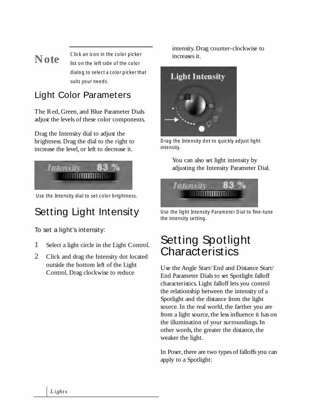
Light Color Parameters
The Red, Green, and Blue Parameter Dials adjust the levels of these color components.
Drag the Intensity dial to adjust the brightness. Drag the dial to the right to increase the level, or left to decrease it.
Setting Light Intensity
To set a light’s intensity:
1 Select a light circle in the Light Control.
2 Click and drag the Intensity dot located outside the bottom left of the Light Control. Drag clockwise to reduce
intensity. Drag counter-clockwise to increases it.
You can also set light intensity by adjusting the Intensity Parameter Dial.
Setting Spotlight CharacteristicsUse the Angle Start/End and Distance Start/End Parameter Dials to set Spotlight falloff characteristics. Light falloff lets you control the relationship between the intensity of a Spotlight and the distance from the light source. In the real world, the farther you are from a light source, the less influence it has on the illumination of your surroundings. In other words, the greater the distance, the weaker the light.
In Poser, there are two types of falloffs you can apply to a Spotlight:
NoteClick an icon in the color picker
list on the left side of the color
dialog to select a color picker that
suits your needs.
Use the Intensity dial to set color brightness.
Drag the Intensity dot to quickly adjust light intensity.
Use the light Intensity Parameter Dial to fine-tune the intensity setting.
L i g h t s

• Angle Falloff sets how the brightness of the light diminishes toward the edge of the light cone. For example, a falloff of 10% means that the light has full intensity from the center to 90% of the radius of the light cone, then decreases linearly to the edge of the cone. You can set a starting falloff angle and an ending falloff angle for every Spotlight.
• Distance Falloff determines the distance from the light itself to the point where the light has no effect. You can set the distance at which a Spotlight starts to fall off and an ending distance—after which no light extends.
To set the angle falloff for a spotlight:
1 Set the Angle Start Parameter Dial to the percentage of intensity present at the start of the cone of light projected by the Spotlight.
2 Set the Angle End Parameter Dial to the percentage of intensity present at the end of the cone of light projected by the Spotlight.
To set the distance falloff for a spotlight:
1 Set the Dist Start Parameter Dial to the distance where light starts to falloff.
2 Set the Dist End Parameter Dial to the distance past which no light extends.
Using ShadowsPoser lights cast shadows. Figures and props produce shadows on each other and on the ground plane when it is displayed. Shadows can add appeal and enhance realism. In animations, moving shadows can be highly cinematic.
To change the cast of a light’s shadow, change the angle of the light. You can also control whether an individual light casts shadows in the Light’s Properties dialog (Object menu> Properties).
As you increase the falloff percentage, you decrease the area that is 100% bright.
100% Falloff 50% Falloff 0% Falloff
Shadows are visible in renderings.
P o s e r 4

Spotlights always render based on the angular range of the spotlight. That means tighter Spotlights produce cleaner shadows. Infinite lights in comparison, adjust the view to fill the screen with all the objects that cast shadows. Because of this, if you render a close-up of a face in a scene which has 30 people, the resulting shadow map does not contain a lot of information.
Shadow Parameter Dials
The light Parameter Dials provide two controls for shadows.
Shadow
Shadow controls the darkness of the shadow cast by this light. You can adjust between a faint shadow and a dark, 100% shadow.
You can animate the shadow strength. Set keyframes of different shadow strength to fade shadow darkness in or out.
Map Size
Map Size sets the resolution of the shadow map for a light. Shadow maps are square, and the value sets the number of pixels in a dimension. Poser uses a map image to apply shadows to objects in the scene. It develops imagery (the shadows) in these maps during rendering.
Larger map size values increase the detail of shadow shapes, but that extra detail takes longer to render. Each map requires memory. For example, a 1024x1024 map needs around 4 MG, a 2048x2048 map requires 16 MG. Each map also adds to the amount of memory needed during rendering.
Depth cannot be animated. The setting applies to the light throughout the file.
Setting a ParentPoser lets you attach lights to body parts or props. When you pose the body, the attached light maintains its contact and orientation with the parent part.
To attach a light to a body element:
1 Add or select a light.
2 Choose Object menu> Set Parent and select from the list the body part to which you want the light attached.
NoteShadows are only visible after
rendering.
NoteAdvanced users can open the
animation palette and select a
shadow camera attached to a
light to adjustment that camera
so that it zooms in on a subject.
L i g h t s

Saving Light SetsIf you set the lights in a way that you want to use again, save the lighting environment as a light set to the Lights category in the Poser Library, where you can easily retrieve it.
The Lights category saves the current settings for the lights, including the map size.
To save a light setup:
1 Set up your lights.
2 Display the Libraries palette by clicking the handle at the far right side of the screen.
3 Click the Lights category. If the category is not visible, move the cursor over the category dots until the Lights category appears and then click the mouse button.
4 Click the Add to Library (+) icon. The New Set Name dialog appears.
5 To specify parts of the scene to include or not include, click the Select Subset button. In the Hierarchy Selection list that appears, deselect any items in the scene that you don’t want to include, then click OK.
6 Enter a name for the new light set and click OK.
A dialog appears asking if you want to save a Single frame or a multi-frame animation.
• If you select the Single frame option, the current lighting setup is saved.
• If you select the Multi-frame animation option, you can specify a range of frames to save.
7 Choose either Single frame or Multi-frame animation and click OK.
The new light set appears in the Light category.
P o s e r 4

L i g h t s


9Animating Figures
Poser 4 lets you animate your figures, adding motion to your scenes. You can use your work in multi-media projects, on Web pages, and in video projects.
When you’ve developed an animation in Poser, you can save it as a movie in QuickTime, in AVI, or as sequential image files. You can open animation files in a motion-graphics application, where you can add effects and perform other post-production tasks.
You can create Poser animations of any length; however, it’s easier to create relatively short animations. You can use a movie-editing program to splice animation clips together.

How Animation WorksPoser uses a technique called keyframe animation to simulate motion based on static figure poses. In keyframe animation, you set up poses at different points in time, called keyframes, and Poser fills in the gaps, creating an illusion of motion. This way you don’t have to keep posing your figure each time you want to create a motion. All you have to do is set up the starting position of the action and the ending position. Poser takes care of the rest.
Poser fills in the gaps between keyframes using a process called interpolation. Interpolation determines how intermediate poses (that is, the poses in between the start and end poses), are created. There are four types of interpolation:
• Spline, which places intermediate poses (and settings) on a curve.
• Linear, which places intermediate poses at equal increments so the motion is smooth and straight.
• Break Spline, which has no intermediate poses. Position changes abruptly only at the keyframes.
• Constant interpolation, which maintains a keyframe position, then instantly changes to the next pose.
Refer to “Keyframe Interpolation” on page 224 for more on interpolation.
Animation Tools
There are two animation tools in Poser: the Animation Controls and the Animation palette. The Animation Controls let you quickly set up and preview animations using a simple click and drag interface. Refer to “Creating Animations” on page 209 for more on the Animation Controls.
The Animation palette lets you edit keyframe positions and create more complex animations. It also lets you animate individual body parts and edit the keyframes within your animation. Refer to “Editing Animations” on page 213 for more on the Animation palette.
What You Can AnimateYou can make any series of changing images into an animation. The “change” can be of any description. Virtually any type of change you can make in Poser can be animated.
Regardless of what you animate, you go about it in the same way—by setting keyframes at the start and end of each action (change).
Animating Figures
Figures can change positions and move about the studio. They walk, dance, climb, fight, tumble, fly, and fall to earth.
Often, you create the illusion of movement by changing the pose of a figure. However, you can also create animation using the Scale tool.
A n i m a t i n g F i g u r e s

When animating figures, keep these points in mind:
• You can set Inverse Kinematics (IK) for the legs and arms of any figure. IK is a global setting; there can only be one IK setting per animation. You cannot set IK on in one keyframe and off in the next.
• Turning IK on or off can affect interpolated motion. For this reason, whenever you change the status of IK for any limb, Poser 4 creates keyframes that secure the motion approximately “as is.”
• Inverse Kinematics determines the pose of some body parts based on the pose of another part. For example, the knee may be bent but the shin won’t have a keyframe. The foot or hip, one of which is keyframed, determines how and when the shin bends.
For more information on IK refer to “Inverse Kinematics” on page 111.
Animating Hands
You can create animated hands just as you would animate any other body part. By creating a starting and ending position for the fingers on a hand you can create almost any type of hand motion.
Animating Faces
Like hands, the faces on Poser’s People figures are fully articulated, meaning that you can animate facial expressions. Facial animations can be extremely powerful. With a moving face, you can simulate a wide range of emotions and even speech.
The Poser libraries provide a series of phoneme presets to help you simulate speech motions. The phoneme presets do not provide all the facial positions you need to create fully realistic speech, but you can use them as a starting point. For more information on simulating speech, refer to “Faces and Phonemes” on page 132
Example of an animated figure.
Example of animating a hand.
Example of animating a face.
P o s e r 4

Animating Props
Props can move, rotate, and change size. A ball can bounce. An axe can swing. A chair can be overturned. Use the Set Parent feature to attach props to the figure. This keeps props moving with the figure through any pose.
For more information on setting prop parents refer to “Setting Prop Parents” on page 171.
Animating Deformers
Magnet Deformers
The Magnet deformer distorts an object by creating a virtual magnet which stretches it. Magnet behavior, the Magnet Base, and the Magnet Zone can all be changed. You can also rotate, twist, translate, and scale a Magnet deformer and capture the effects in an animation.
For more information on using Magnet Deformers, refer to “The Magnet Deformer” on page 144.
Wave Deformers
A Wave deformer distorts an object by creating a wave path for it. Waves can rotate, move, and change size. You can switch between wave types. The Wave zone can be changed. You can change Wave amplitude, Wavelength, and Stretch settings. Noise parameters can be adjusted, Turbulence added, or an Offset can be set. Easy examples of animating a Wave Deformer are causing a flag to wave or creating the effect of moving water.
Example of animating a prop.
Example of animating the effect of a Magnet Deformer on an object.
A n i m a t i n g F i g u r e s

For more information on creating Waves, refer to “The Wave Deformer” on page 149.
Morph Targets
A morph target is a custom Parameter for a body part that enables you to gradually reshape it. You can create morph targets for figure elements, full body morphs, or morphs that work on grouped parts. Reshaping an object using a morph target can be animated.
For more information on creating Morph Targets, refer to “Creating Custom Morph Targets” on page 154.
Creating AnimationsThe Animation Controls, located at the bottom of the screen, are the tools you use most to create animations. They contain controls for adding keyframes, editing keyframes, and previewing animations.
The main area of the Animation Controls displays the Timeline. The Timeline represents time in Poser. The Scrubber on the Timeline represents the current time. By positioning the Scrubber at different points in time you can move through time setting up keyframes. The counter in the center of the controls shows you which frame you’re currently viewing in the Document window.
The controls on the left side of the Animation Controls let you preview all the frames on the Timeline. You can play all the frames or step through all the frames one at a time.
The controls on the right side of the Animation Controls let you edit the keyframes on the Timeline. You can add, delete, and preview keyframes.
Example of animating a the effects of a Wave.
Example of animating the effect of using a Morph Target.
The Animation Control’s Time Display Area controls the creation and playing of animations.
TimelineScrubber
Preview controls
Keyframe controls
Frame indicator
P o s e r 4

Setting Up Your Animation
When you begin an animation, you set the dimensions and duration of your project.
To set up an animation:
1 Choose Window menu> Document Window Size. Set the dimensions of the Document window according to the aspect ratio of the frame size you want.
The Document window need not equal the frame size for your intended animation output, but it must be consistent with the aspect ratio.
Any aspect ratio is acceptable. For an extremely wide animation, you could use an aspect ratio of 3:1 and create a window that’s 600 x 200.
If you are working with an imported background—either still or moving—you can import that file now. Poser asks if you want to set the dimensions of the Document window to match the imported background.
2 Choose Animation menu> Animation Setup. Poser displays the Animation Setup dialog.
3 In the Frame Size field, enter either the width or height value for the animation output you want. The aspect ratio of the Document window determines the other value.
4 Set a Frame Rate. Frame Rate determines how many frames are displayed each second.
NTSC video plays at 30 frames per second (fps). Film plays at 24 fps. Many computer animations work quite well at 12 to 15 fps. Animations for display on the World Wide Web can be successful with as few as 8 frames per second.
5 Set either the Frame Count or the Duration. These values are interdependent. Set one, and Poser fills in the other.
• Frame Count is the total number of frames in the animation.
• Duration describes how long the animation lasts. The display uses the SMPTE standard—hours: minutes: seconds: frames.
The Document window Aspect Ratio dialog.
The Animation Output Settings dialog.
A n i m a t i n g F i g u r e s
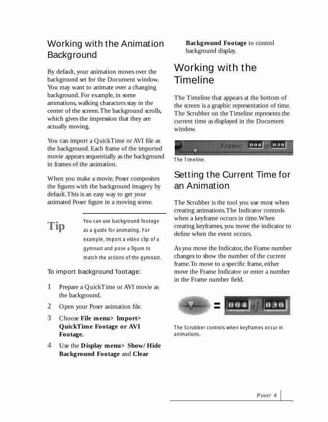
Working with the Animation Background
By default, your animation moves over the background set for the Document window. You may want to animate over a changing background. For example, in some animations, walking characters stay in the center of the screen. The background scrolls, which gives the impression that they are actually moving.
You can import a QuickTime or AVI file as the background. Each frame of the imported movie appears sequentially as the background in frames of the animation.
When you make a movie, Poser composites the figures with the background imagery by default. This is an easy way to get your animated Poser figure in a moving scene.
To import background footage:
1 Prepare a QuickTime or AVI movie as the background.
2 Open your Poser animation file.
3 Choose File menu> Import> QuickTime Footage or AVI Footage.
4 Use the Display menu> Show/Hide Background Footage and Clear
Background Footage to control background display.
Working with the Timeline
The Timeline that appears at the bottom of the screen is a graphic representation of time. The Scrubber on the Timeline represents the current time as displayed in the Document window.
Setting the Current Time for an Animation
The Scrubber is the tool you use most when creating animations. The Indicator controls when a keyframe occurs in time. When creating keyframes, you move the indicator to define when the event occurs.
As you move the Indicator, the Frame number changes to show the number of the current frame. To move to a specific frame, either move the Frame Indicator or enter a number in the Frame number field.
TipYou can use background footage
as a guide for animating. For
example, import a video clip of a
gymnast and pose a figure to
match the actions of the gymnast.
The Timeline.
The Scrubber controls when keyframes occur in animations.
P o s e r 4

The Scrubber also controls which portion of your animation is displayed in the Document window. When the Indicator is at the beginning of the Timeline, the first frame of your animation shows. As you move the indicator, you see how your pose changes over the course of your animation.
To move the current time manually:
• Drag the Scrubber along the Timeline. As you drag, note that the Time Display area shows the current frame number in your animation.
Release the mouse button when you reach the desired frame.
To move the current time numerically:
1 Click the frame number in the Time Display area. A text field appears.
2 Enter the number of the frame you want to move to and press Return/Enter. The Scrubber jumps to the specified frame.
Recording Keyframes
When camera animating is On, Poser records changes you make to your Poser figures as animation keyframes. You create keyframes by moving the scrubber to a new point on the timeline, then making a change to a Poser figure, object, prop, light, or camera.
A recorded keyframe stores changes in the position of each body part in the figure. It also stores changes in scale, color, lighting, or camera position. Since you can store one set of positions and parameter settings at any given point on the timeline, Poser saves the last changes you make, until the scrubber is
moved to a new point in time. For example, if you move an arm up and then down while the scrubber remains at the same location in the timeline, the down motion is recorded for that keyframe. To make an arm move up and then down, record the up motion in one keyframe, then move to a different keyframe to record the down motion.
To record keyframes:
1 If necessary, click the Animating On/Off Key icon in the Camera controls to turn the Poser animation system On for the current camera.
Camera Animating is On by default. When Off, the Animating On/Off Key is red.
2 Move the Scrubber to a position in time.
3 Use the Editing Tools to adjust the pose of your figure or make an adjustment to a camera or light. A new keyframe is created.
4 Move the Scrubber to a different point on the timeline and change something else.
5 Continue creating keyframes until your motion sequence is complete.
Click the Animation System Key by the Camera control to toggle the system between On and Off.
A n i m a t i n g F i g u r e s

Adding and Deleting Keyframes
In most cases, the Animation System is used to automatically record keyframes for your animation. Sometimes, you’ll want to instruct the Animation system to explicitly create a keyframe, like when Animating for the current camera is set to Off and no keyframes are being recorded.
For example, you set the Scrubber to a point in the timeline, then make a number of changes—not realizing that Animating for the current camera is set to Off. Because the system is turned Off, you must manually create a keyframe to store the results of your changes. If you don’t create a keyframe, when you move the scrubber to a new point on the timeline the changes you’ve just made are discarded.
You might also want to add a keyframe to fine-tune movements recorded by the Animation System. For example, at frame number 10, the figure’s left foot is flat on the ground. You move the scrubber to frame 20, then make a change to the position of the left foot. The Animation System records that change, then calculates positions for the left foot for all those "in-between" frames. To further refine the "in-between" frames, you could move the Scrubber to frame 15, reposition the left foot in an intermediate pose, then explicitly add a keyframe to store that change.
The Animation Controls let you quickly add and delete keyframes. When you delete a keyframe, all the stored properties for the figures are deleted. When you add a keyframe, the figure’s current position in the Document window is saved as a keyframe.
To add a keyframe:
1 Move the Scrubber to the desired point in time.
2 Click the Add Keyframes (+) button.
To delete keyframes:
1 Click either the Previous Keyframe or Next Keyframe button until the keyframe you want to delete is displayed in the Document window.
2 Click the Delete Keyframes (-) button.
Editing AnimationsThe Animation palette is where you edit the keyframes in your animation. The palette shows the layout of the keyframes and provides for setting and navigating between them. The palette also provides controls for playing animations.
The Keyframe controls allow you to add and delete keyframes.
De ete Keyframes
Disp ay Animation palette
Add Keyframes
Previous Keyframe
Next Keyframe
P o s e r 4

To display the Animation palette:
• Choose Window menu> Animation Controls.
or
Click the Display Animation Palette button on the right side of the Animation Controls.
When you first display the palette, it shows all the keyframes you’ve previously created using the Animation Controls.
The Animation palette is divided into the following sections:
• The Setup controls are used to set Frame Rate, Duration, Frames, and display options for the Timeline Area. These controls also let you preview your animation and navigate through the keyframes.
• The Elements List displays all the objects in the studio. Figure-type elements contain a listing for each of the parts that make up that figure.
• The Timeline Area, displays all the keyframes stored for each of the body parts. Keyframes are displayed as red squares in the grid and interpolated
frames are shown in different colors to identify the interpolation type. An interpolated frame is an animation frame created by Poser to fill in the gaps between keyframes.
Editing Animation Setup
You can use the Animation palette’s Setup controls to edit your animation setup parameters. Many of the controls in this palette can also be accessed from the Animation Setup dialog (Animation menu> Animation Setup).
Changing the Frame Rate
Frame Rate determines how many frames are used during each second of action. Thus, frame rate is measured in Frames Per Second (fps). Higher frame rates have more frames in a second, producing smoother motion, but require more time to render.
To edit the frame rate:
1 Click the FrameRate indicator at the top of the Animation palette. A text field appears.
2 Enter a frame rate.
The Animation palette allows you to edit keyframes.
nterpo ation Controls
Preview Controls
Radio buttons indicate what is affected
Preview Range
Keyframe Controls
Elements List
Timeline Area
Setup Controls
The Animation Palette’s setup controls.
A n i m a t i n g F i g u r e s

You can also click the arrow icon next to the Frame Rate indicator and pick a frame rate from the menu
Moving the Current Time
The Current Time display lets you keep track of the current time shown in the Timeline area, and lets you change the current time.
As you edit keyframes in the Timeline Area, the display changes to show you the current time in SMPTE format (Hours: Minutes: Seconds: Frame). You can also enter a time to display a specific point in time.
To move to a specific time:
1 Click one of the Current Time display fields. A text field appears.
2 Enter the hour, minute, second, or frame you want to see.
Changing the Number of Frames
The two Frame indicators show you the number of the currently selected frame and the total number of frames in the animation. You can move to a specific frame by selecting the Frame field and entering a frame number.
To change the total number of frames in your animation, click in the Total Frames field and enter a new value. When you change the total number of frames you set the maximum number of frames in your animation. If you have more frames in the animation than the Total Frames value, frames are deleted.
Viewing the Elements List
The Elements List displays all the figures, lights, cameras, and props currently in the studio. The listing for a figure can be expanded to display all the objects that make up that figure. Each object within a figure can be further expanded to display all the properties of that object. For example, you can view the Scale or Translation keyframes.
Using this listing, you can select an object or studio element you want to animate.
The Frame indicators. Elements List in the Animation palette.
Elements listing
Currently selected object or element
Collapsed listing
Expanded listing
Property listing
P o s e r 4

Selecting Elements
You can select an element by clicking on it in the Elements List. Selecting an object here is equivalent to clicking on it in the Document window or choosing it from the Current Element popup at the bottom of the Document window. Poser highlights the name and grid row of the selected object.
To scroll down the list of elements:
• Drag the vertical scroll bar.
Collapsing the Elements List
Each figure has many parts, and each part has many properties. This can make for a very long Elements List. You can collapse any of the figure listings to save space, or expand them to show more detail. When you are not working with a particular figure, you can collapse its listing. This shortens the Elements List and makes other objects easier to locate.
To collapse/expand a listing:
1 Click the triangle next to the figure name.
A down-facing arrow indicates that a listing is expanded. A right-facing arrow indicates a collapsed listing.
2 Click the triangle again to collapse the list.
The hip is the selected element.
Scrolling through the Animation palette to display additional elements.
Vertical scroll bar
NoteWhen you collapse a Figure in the
Elements List, the keyframe line
displayed controls the figure’s
position in the studio. Posing
changes only show when the
listing is expanded.
You can collapse or expand the elements listing in the Animation palette.
A n i m a t i n g F i g u r e s

Editing Keyframes on the Timeline
You can use the Timeline area to select keyframes, edit their position, or delete them from the animation. You can also add new frames for specific properties or objects.
The Timeline area displays time as a grid. The grid displays the keyframes for each of the items in the Elements List.
Time is displayed as columns. Each column can represent either a specific point in time or a frame in the animation. The Ruler at the top of the area indicates whether the columns represent points in time or frames.
Each object or property in the Elements List is represented on a row in the Timeline area.
Keyframes appear as red squares. Interpolated frames between frames appear in different colors depending on the type of interpolation used to create them. Green denotes Spline interpolation, and red denotes Linear interpolation.
To change the Timeline Ruler display:
• Click the Options label at the top of the palette, and choose Display Frames or Display Time Code from the menu.
Selecting Keyframes
Poser starts with the first frame selected (frame #1). You can select any frame by clicking in, or above, its column. You can also enter a number in the Frame field at the top of the palette. Poser displays the number of the frame and highlights the column.
When you select a keyframe, the item’s row and the time column is highlighted, creating an intersection. Selecting another keyframe moves the intersection to a different point.
To select a keyframe:
• Click one of the dark red squares on the grid.
Timeline Area on the Animation palette.
Timeline Ruler Current Time tab
Scroll bars Play Selected Range bar
The hip is the selected object. Frame #6 is the current frame.
The Frame scroll bar appears when there are more frames than the window can display.
P o s e r 4

To scroll across frames:
• Drag the horizontal scroll bar. The scroll bar only appears when the number of frames exceeds what the window can display.
Adding Keyframes
You can add keyframes to store a specific pose or save an interpolation frame created by Poser.
Keyframes can be added for a specific object or property using the This Element option. When enabled, any keyframe you create is only applied to the selected element.
You can also use the All Elements option to add frames to store all changes for all the elements in the animation at a specific point in time. This creates a kind of checkpoint. Once all element properties are saved into keyframes, you can experiment with poses in the remaining part of the animation while leaving the first half of your animation unchanged.
To add a key for one element:
1 Select the frame where you want to add the new keyframe.
2 Click the This Element radio button.
3 Select the object you want to set.
4 Click the Add Keyframes (+) button.
To add a key for all elements:
1 Select the frame where you want to add the key.
2 Click the radio button for All Elements.
3 Click the Add Keyframes (+) button.
To add a keyframe for a selected element, click the Add Keyframes button for This Element.
Add a keyframe for this element.
To add a keyframe for the entire figure, click the Add Keyframes button for All Elements.
A n i m a t i n g F i g u r e s

Clearing Keyframes
At some point, you may decide to remove a keyframe. Once a keyframe is removed, the animation changes.
You can clear a keyframe for a single object/element or for all objects/figures in the scene.
Clearing does not delete the frame. It removes the settings that make this frame a keyframe. The frame is still in the animation, but it does not have a key assigned to it. Once the keyframe is removed, the values at that frame are recomputed to properly blend with neighboring keyframes.
To clear a keyframe for one element:
1 Move the Current Time tab to the point in time where you want to clear the keyframe.
2 In the Elements List, select the figure part whose keyframe you want to clear.
3 Enable the This Element radio button.
4 Click the Delete Keyframes (-) button. You can also press the Delete/Backspace key.
To clear a keyframe for all elements at a given point in time:
1 Move the Current Time tab to the point in time where you want to delete the keyframe.
2 Enable the All Elements radio button.
Add a keyframe for all elements. Notice the color changes in keyframe #8.
To clear a keyframe for one element/object, click the Delete Keyframes button for This Element.
After clicking Delete Keyframe, the keyframe is removed and Poser interpolates between the previous and next keyframe.
P o s e r 4

3 Click the Delete Keyframes (-) button. You can also press the Delete/Backspace key.
To clear a range of keyframes:
1 Shift-drag over the range of frames you want to clear.
2 Press the Delete key.
To clear specific keyframes:
1 Press Shift and click each of the frames you want to delete.
2 Press the Delete key.
Navigating the Timeline
You can move to a keyframe in the Timeline using the Navigation controls at the top of the palette. The This Element and All Elements radio buttons let you move to the keyframes for a selected element or to keyframes for any element.
To advance to the next keyframe for a specific element:
1 Click the row for the desired element.
2 Enable the This Element radio button.
3 Click the Next Keyframe button.
To move back to the previous keyframe for a specific element:
1 Click the row for the desired element.
2 Enable the This Element radio button.
3 Click the Previous Keyframe button.
To clear a keyframe for all elements, click the Delete Keyframes button for All Elements.
The selected keyframes are cleared for all elements at this time.
To advance to the next keyframe for a given element, click the Next Keyframe button for This Element.
To move back to the previous keyframe for a given element, click the Previous Keyframe button for This Element.
A n i m a t i n g F i g u r e s

To advance to the next keyframe (for any element):
• Click the Next Keyframe button for All Elements.
To move back to the previous keyframe (for any element):
• Click the Previous Keyframe button for All Elements.
To go to a specific frame:
1 Click to highlight the current frame display.
2 Enter the value you want. Press Return/Enter.
Moving Keyframes
As you work, you may decide you want certain keyframes to occur sooner, or later, or that you want to use the settings in one keyframe somewhere else in the animation. Poser makes this easy by allowing you to move keyframes or groups of keyframes.
To move a keyframe:
1 Click the keyframe to select it.
2 Drag the colored grid cell horizontally to the frame where you want it.
To advance to the next keyframe for any element, click the Next Keyframe button for All Elements.
To move back to the previous keyframe for any element, click the Previous Keyframe button for All Elements.
The current frame display lets you jump to a specific frame.
Select an element and a frame.
When you click on the grid cell, the cursor turns into a four-way arrow. Drag the keyframe to where you want it.
P o s e r 4

To move a block of frames:
1 Drag a marquee around all the frames you want to move, or Shift-click the desired frames.
Poser outlines the selected block of frames.
2 Drag the block of frames to a different position on the Timeline.
Copying Keyframes
You can copy keyframes, figure parts, and parameters in the Elements Listing. There are no limits to how little or much you can copy. For example, say you’ve fine-tuned movements over the course of an animation for parts in a Poser figures, like the Left Thigh, Left Shin, and Left Foot. You can copy
keyframes and the parameter settings they represent for those parts, then paste them to other figures. In this way you could bring a set of marching Poser figures into perfect step.
Although you can copy and paste keyframes across elements and objects, copying data to inappropriate parameters, like scaling data into rotation parameters should be avoided. Pasting body part parameters from left to right or
Select a block of frames by Shift-clicking.
Drag a block of frames to a new location.
By copying elements between figures, you can bring a set of marching figures into perfect step.
A n i m a t i n g F i g u r e s

right to left can also give unexpected results. Because they are on opposite axis, you must make the copied parameter negative to get a symmetrical position.
To copy a keyframe to a new position on the timeline:
1 Click the keyframe to select it.
2 Option/Alt-drag the keyframe to the point in time where you want it to appear. When it’s positioned, release the mouse button, then release the Option/Ctrl.
To copy a block of frames to a new position on the timeline:
1 Drag a marquee around all the keyframes, elements, or parameters you want to copy, or Shift-click the desired elements.
2 Choose Edit menu > Copy, or press Ctrl/Cmd+C to copy.
3 Drag a marquee around the area where you want to paste the copied information.
4 Choose Edit menu > Paste, or press Ctrl/Cmd+V.
Poser pastes the copied information into the selected area of the palette.
Retime Keyframes
The Animation menu> Retime Animation command lets you take a motion or a set of keyframes and change the amount of time it takes for that motion to occur.
The Retime Animation command doesn’t destroy any keyframes inside the source range and outside the destination range, so you can use it to repeat motions by copying them from one time to another. By selecting a motion in one area and selecting a non-overlapping destination, you remap the motion to another time without deleting the original motion.
To set retime keys:
1 Choose Animation menu> Retime Animation. A dialog appears asking you to fill in your Source and Destination frames.
2 For the Source frames, enter the start and end frames for the section of animation you want to retime.
3 For the Destination frames, enter the range of frames to retime the animation to.
• If the destination range is longer than the source range, the animation is expanded, or slowed down.
• If the destination range is shorter than the source range, the animation is compressed, or sped up. Old
Pasting body part parameters from left to right or right to left gives unexpected results.
P o s e r 4

keyframes that were previously in the destination range are deleted. The keyframes that were in the source range are retimed and placed in the proper time in the destination range.
4 Click OK.
Advanced EditingThe following section deals with editing an element’s animatable properties and applying different interpolation methods. Both techniques are advanced features of Poser, so become comfortable with the animation process before trying these techniques.
Keyframe Interpolation
Poser interpolates the intermediate figure poses and element settings between keyframes. Interpolation refers to the way Poser calculates the “in between” position of objects/elements.
You have several options for the rules used to interpolate the poses or settings. In this way, you can make subtle changes in the animated motion.
Interpolation settings apply to a range of frames. This means you can use one interpolation type prior to a keyframe and another after it.
If the beginning and end of a selected range does not already have keyframes, changing interpolation type will automatically insert keyframes at the beginning and ending frames.
You can apply the following types of interpolation to your keyframes:
• Spline places intermediate poses (and settings) on a curve. The element/object accelerates and decelerates in and out of the motion.
• Linear places intermediate poses at equal increments so the motion is smooth and straight. The speed of motion does not change in between keyframes, but can change speed suddenly at keyframes
• Constant has no intermediate poses; changes occur abruptly only at the keyframes. Whereas previous versions of Poser limited the use of Constant interpolation to the end of an animation, Poser 4 allows you to use it at any point
An example of Spline interpolation.
An examples of Linear interpolation.
A n i m a t i n g F i g u r e s

where abrupt change at a keyframe is required.
• Break Spline stops the interpolation at the break point, so that another type of interpolation can begin. This type of interpolation is useful for ending a series of interpolated frames to begin a fresh series.
For example, a bouncing ball has a smooth arc until it hits the floor and then starts off in another arc. With Break Spline you can create this type of abrupt change in the arc.
You can use different interpolation options depending on the motion you want. Using a walk as an example, you would use Spline interpolation for the keyframes of a foot while it’s moving through the air. However, you would use Linear interpolation while it’s on the ground to make it easier to keep it planted.
Interpolation types are shown in different colors on the Animation palette. Green is used for Spline, and red for Linear. A cross in the keyframe indicates that Break Spline has been applied. Keyframes that use Constant interpolation are grayed out.
To choose an interpolation method:
1 Select a range of keyframes in the Timeline Area.
2 Click one of the four Interpolation Controls.
Editing Keyframe Interpolation
The Graph palette let you perform precise edits on keyframes and adjust the interpolation methods used in the your animation.
To display the Graph palette:
• Click the Show Graph Display button on the Animation palette.
You can also double-click on an element or keyframe to display the graph for that element.
An examples of Constant interpolation.
Select one of the Interpolation Controls.
The Show Graph Display button.
Spline Linear Constant Break Spline
P o s e r 4

The palette is made up of two axes and a graph. The horizontal axis represents time in your animation, displayed as frame numbers.
The values in the vertical axis change depending on the attribute you select. If you choose a position attribute (xTrans, yTrans, etc.) the values on the axis represent positions in 3D space. If you choose a figure editing property (Taper, Bend, Side-to-Side, etc.) the values on the axis indicate degrees of change.
The graph itself shows the actual change in the selected element over the course of the animation. Depending on the selected attribute, the graph shows changes in position, rotation, scale, or tapering. The graph’s shape indicates the type of interpolation used to move from one keyframe to another.
A smooth curve indicates that Spline interpolation is being used, a straight line means that Linear interpolation is being used.
The Graph palette also provides controls for synching sound to motion in your animation. Refer to “Syncing Sound and Motion” on page 240 for more information.
Editing the Graph
You can edit the graph to achieve varying degrees of interpolation. For example, to decrease the amount of Spline interpolation, straighten the curve.
You can set the shape of the curve using the preset interpolation methods or by just dragging the curve’s points until it’s the shape you want. In addition, you can apply different interpolation methods to different parts of the graph.
The Graph palette lets you perform precise edits on keyframes.
Interpolation Methods
Frame Numbers Animatable Properties
Interpolation
Select Frames Add/Delete Frames
Different shapes of the Interpolation graph.
Spline Interpolation
Linear Interpolation
Break Spline Interpolation
Constant Interpolation
A n i m a t i n g F i g u r e s
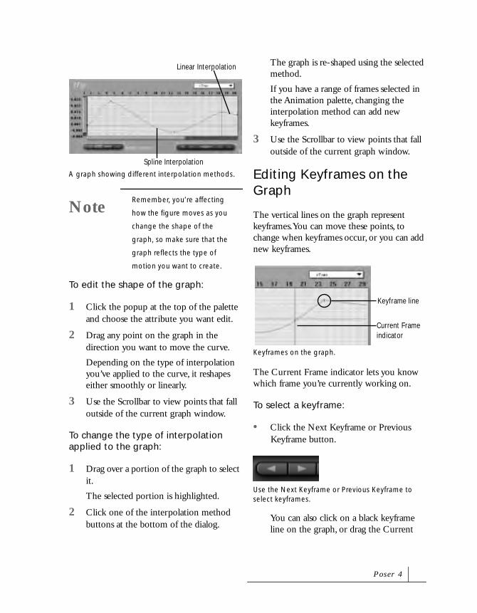
To edit the shape of the graph:
1 Click the popup at the top of the palette and choose the attribute you want edit.
2 Drag any point on the graph in the direction you want to move the curve.
Depending on the type of interpolation you’ve applied to the curve, it reshapes either smoothly or linearly.
3 Use the Scrollbar to view points that fall outside of the current graph window.
To change the type of interpolation applied to the graph:
1 Drag over a portion of the graph to select it.
The selected portion is highlighted.
2 Click one of the interpolation method buttons at the bottom of the dialog.
The graph is re-shaped using the selected method.
If you have a range of frames selected in the Animation palette, changing the interpolation method can add new keyframes.
3 Use the Scrollbar to view points that fall outside of the current graph window.
Editing Keyframes on the Graph
The vertical lines on the graph represent keyframes. You can move these points, to change when keyframes occur, or you can add new keyframes.
The Current Frame indicator lets you know which frame you’re currently working on.
To select a keyframe:
• Click the Next Keyframe or Previous Keyframe button.
You can also click on a black keyframe line on the graph, or drag the Current
A graph showing different interpolation methods.
NoteRemember, you’re affecting
how the figure moves as you
change the shape of the
graph, so make sure that the
graph reflects the type of
motion you want to create.
Spline Interpolation
Linear Interpolation
Keyframes on the graph.
Use the Next Keyframe or Previous Keyframe to select keyframes.
Keyframe line
Current Frame indicator
P o s e r 4

Frame indicator to the frame you want to edit.
To select a range of keyframes:
• Drag an area around the desired frames. A selected area is highlighted in dark grey.
To reposition a keyframe:
• Select a keyframe and drag it to a different position on the graph.
To add a keyframe:
1 Move the Current Frame indicator to the position where you want to add a frame.
2 Click the Add Keyframes button.
To duplicate a portion of the graph:
1 Drag across an area of the graph to select it.
2 Choose Edit menu > Copy (or press Ctrl/Cmd+C).
3 Position the cursor where you want to insert the copy.
4 Choose Edit menu > Paste (or press Ctrl/Cmd+V).
To move a keyframe:
• Command/Ctrl-drag a key or range of keys to a new point in time.
To delete a keyframe:
1 Move the Current Frame indicator to the position where you want to delete a frame.
2 Click the Delete Keyframes button.
Previewing AnimationsYou can preview animations using the VCR style controls in the Animation Controls or the Animation palette.
When you use the Preview controls to preview your animation, the animation plays in the Document window. The quality of the preview depends on the current display style and Tracking mode that’s currently enabled. Refer to “Previewing Your Figure” on page 37 for information about display styles and refer to “Figure Tracking” on page 30 for information about tracking modes.
Play starts the animation. While the animation plays, the readouts display the current frame and time. The Play button becomes the Pause button during a preview.
Stop halts play and jumps the animation to the first frame.
Pause halts play at the currently displayed frame.
Fast Forward advances to the last frame of the animation.
Use the Preview Controls to preview your animations.
First Frame
End Frame Play
Stop Step Back
Step Forward
A n i m a t i n g F i g u r e s

Rewind returns to the first frame of the animation.
Step Reverse moves back one frame.
Step Forward advances to the next frame.
The Loop radio button plays the animation over and over again until you stop the playback.
When disabled, the Skip Frames radio button displays all frames in the animation. When enabled, frames drop from the preview to speed up play.
To preview an animation in the Document window:
1 Click the Play button in the Preview controls.
The Play button becomes the Pause button.
2 Click the Stop button to stop the preview.
To view a specific keyframe:
• Click either the Previous Keyframe or Next Keyframe button in the Keyframe controls.
The Document window changes to display the poses in the selected keyframe.
Setting the Play Range
By default, you preview the entire animation when you click the Play button; however, you can choose to play only a section of your animation. You can adjust the length of the Loop Range bar in the Animation palette to set in and out points for the preview. Only frames between the in and out points play.
To change the range:
1 Drag the end of the Play Range bar to set the in or out point of the preview.
Using the Libraries Palette for AnimationsThe Libraries palette lets you save single frames or multi-frame poses. A multi-frame pose is an animated figure.
The Previous and Next Keyframe controls.
NextKeyframe
Previous Keyframe
The Play Range bar sets which frames will play. In this case, Poser plays all frames of the animation.
Drag the ends of the Play Range bar to set the range of frames. In this case, Poser plays frames 5 through 19.
P o s e r 4

Adding an Animation to the Library
When you add to the Poses category Libraries palette, Poser asks whether you want to save one or multiple frames. For a multi-frame animation, you can specify the range of frames.
When you name the animation for the library, consider including the number of frames in its name. For example, name a listing Strut_48 to indicate that this animation has 48 frames. This information is helpful later when you use the animation.
Using a Multi-Frame Animation from the Library
When you use an animation from the library, Poser applies it to a series of frames, beginning with the current frame. The series extends the number of frames in the saved animation. However, it does not exceed the number of frames in the current document. You may have to increase the number of frames in the animation to make room for all the keyframes in the saved pose.
Scale changes are not stored in pose sets. This allows you to use stored poses for reproportioned figures without modifying their scale. Animated scale changes are not stored in pose sets.
To add a multi-frame animation from the Libraries palette:
1 If the scene has more than one figure, select the figure you want to apply the animation to.
2 Select the frame where you want the animated sequence to begin. Frame #1 of the library animation applies to the current frame.
3 Make sure you have enough frames to accommodate the multi-frame pose. You may need to add frames to the file or move a set of keyframes farther to the right.
4 In the Libraries palette, click the Poses category button.
5 Click the Poses popup and choose Animation Sets.
6 Double-click the preview of the set you want to use.
A n i m a t i n g F i g u r e s

10Animation Techniques
The animation process begins with the creation of keyframes and poses, but it certainly doesn’t stop there. A simple jerky motion can become a smooth flowing one, if you just know a few techniques for using Poser’s tools to their full potential.
The techniques described in this chapter will help you create more realistic motion and enhance your basic animations.
Setting KeyframesHow do you know how to space keyframes? You have to consider time and frame rate. You should space keyframes so that at the chosen frame rate, the animated action takes the right amount of time.

• Frame Rate x Duration = Number of Frames
The duration refers to how long it should take the figure to move from Point A to Point B.
For an example, we’ll look at a simple animated action—getting up from a chair. In this action, the extremes are (1) sitting in the chair (2) standing in front of the chair. These are the keyframes we’ll set.
Decide on the duration of the action. You may want to time yourself getting up from a chair to get a better idea. Let’s say the action should take three-quarters of a second (0.75 sec).
At a 30 frame per second rate, you can calculate the number of frames for the action: 0.75 • 30 = 22.5
Dropping the decimal, you see it should take 22 frames to complete the action.
With the first keyframe (sitting in the chair) at frame #1 of the Poser animation, you should place the second keyframe (standing in front of the chair) at frame #21.
Set these keyframes, then work in, adding more keyframes to improve the motion.
Creating Realistic MotionThe key to human motion is to examine the parts of the move. If you look at a baseball player’s swing, it looks like the arm is simply moving in an arcing motion. However, on closer inspection you can see that the motion is a combination of the hips, shoulder, hand, neck, head, back and arm. To create this kind of motion in Poser, you work from the large motions to the smaller ones.
The first thing you do to create a motion is “rough out” the larger movements. In the case of the baseball swing, determine where the arm starts at the top of the swing and where it ends up a the end of the swing. In Poser, these two points are determined by two keyframes: one for the start, the other for the end.
Once the larger motions are set up, you can start adding in the smaller, more subtle, motions. Continuing the baseball swing example, start by adding in the hip swings, the shoulder tilt and so on. It is these smaller motions that make the entire action look
Two examples of keyframes.
A motion starts with large actions.
A n i m a t i o n Te c h n i q u e s

realistic. Poser’s Animation palette is ideal for adding these little motions. In the palette, you can add keyframes in between the frames for the start and end of the swing.
Working this way, you an create almost any kind of action. When you start, first examine the big movements, then fill in the smaller, or secondary motions, in between the big movements.
Making Your Figure WalkOne of the most complicated human motions to simulate is the simple act of walking. What appears on the surface to be a rather straightforward matter—just put one foot in front of the other—is actually an incredibly complex interaction between a variety of muscles in the legs and torso. Realistic
walking motion would normally take a great deal of precision posing. However, with the Walk Designer, it is just a matter of setting up a few parameters and letting Poser do the rest.
Creating a walking figure is a two step process: first determine the walking path through the studio, then determine how the figure walks.
Creating a Walk Path
Before you design how the figure walks, you must determine where it walks. This is what the Walk Path is used for. The path is a line or curve you draw in the Document window to set the figure’s course as it moves about the studio. When you apply the walk, the figure starts walking a the start of the path and stops at the end of the path.
To draw a walk path:
1 Choose Figure menu> Create Walk Path. A path appears in the studio.
The more you examine a motion, the more you see the smaller, or secondary motions, that make up the action.
A Walk Path in the studio.
P o s e r 4

2 Click one of the Editing Tools and adjust the position or shape of the path.
Click on a point to reshape the path, or click on the ring that surrounds the entire path to reposition it.
Designing a Walk
Walks are designed in the Walk Designer. As its name suggests, the designer lets you create realistic walking motions which you can apply any human figure. The designer has two sections: the upper set of controls let you create the larger motions of a walk, the lower set of controls let you set up the secondary motions of a walk.
The designer provides a real-time preview of the walk. As you change the parameters, the walking figure in the preview also changes. Load in a prototype style that matches the figure-type you’re animating and see an even more realistic preview.
To design a walk:
1 Choose Window menu> Walk Designer. The Walk Designer dialog appears.
2 Click Figure Type to select a preview style that matches the figure-type for which you are designing a walk.
In the Poser: Runtime: Libraries: Characters: People folder, select the prototype style you want to preview.
Use the Walk Designer to define the characteristics of the walk.
TipChanges you make to the
foreground, background, and
shadow colors in your Poser
Workspace are reflected in the
real-time preview in the Walk
Designer.
NoteUsing a Figure Type is not
required, but be sure to select a
Figure Type if you need to collect
walk data for articulated body
parts present in your Poser figure,
like articulated feet or hands.
Poser 3 Low Res Figure Types
work well for this purpose.
A n i m a t i o n Te c h n i q u e s

3 Click Walk to start the real-time preview of the walk.
4 Drag the Blend Styles sliders to set the large motions of your walk.
5 Drag right to increase the intensity of an action, or left to decrease the action.
Try several settings in conjunction. You may have to combine more than one attribute to get the desired walk type.
6 Adjust the positions of the Tweaks sliders to set the smaller, or secondary, motions of the walk.
You can click Defaults to reset the sliders to their default positions.
7 Click Apply to apply the walk to a Walk Path.
The Walk Apply Dialog appears.
8 Set walk options and click OK. Refer to “Applying a Walk” on page 236 for more on walk options.
Click Done to exit the dialog without applying the walk.
Editing a Walk
A Walk Path is a spline curve that always lies on the ground (the z-component is always zero). You can edit the shape of the curve by adding, deleting, and moving its control points.
To add a control point:
• Click a point on the curve (not on a control point).
To move a control point:
• Click a control point, then drag.
To delete a control point:
• Alt/Option click a control point.
Saving a Walk
A walk path is a special kind of prop. You can save the path in the prop library to reuse later. You can use editing tools, like scale or rotate to transform the walk path, as you would other types of props.
Using a Figure Type that matches your Poser figure-type assures collection of walk data for articulated body parts present in your Poser figure.
NoteUsing a preview Figure Type
slows the real-time preview.
NoteThe default walk path is a
spline curve with four control
points. You can create a
straight line by deleting the
middle two control points.
P o s e r 4

To save a walk:
1 Set up your walk by adjusting the sliders.
2 Click Save.
3 Choose a location and filename for your walk and click Save.
4 Click Done to exit the dialog, or click Apply to apply the walk to a Walk Path.
Loading a Walk
To load a walk:
1 Click Load. The Open dialog appears.
2 Locate the walk you want to load and click OK.
Applying a Walk
There are several options you can set when applying the walk to a Walk Path.The WalkApplyDialog provides options for setting where the walk begins, how the walk effects the animation, and the behavior of the figure as it walks.
To display the WalkApplyDialog:
1 Choose Window menu> Walk Designer. The Walk Designer dialog appears.
2 Set your walk characteristics as described in the previous section and click Apply. The Walk Apply Dialog appears.
Start Frame and End Frame
When you apply a walk, you can set the frame where it begins and the frame where it ends. The more frames you assign for the walk, the more natural the motion is.
Figure and Path
If you have more than one figure or path in the studio, you can use these popup menus to choose a specific Figure to use for the walk and a specific Path to follow.
Walk In Place
This option makes the figure walk in a single spot. When this option is enabled, the figure does not walk along the path.
The WalkApplyDialog.
A n i m a t i o n Te c h n i q u e s

Cycle Repeat
This field indicates how many times you want a walk to repeat along the path.
Always Complete Last Step
This option forces the walk animation to complete within the allotted time. If you find that the walk stops in mid-stride at the end of your animation, enable the option. This forces the walk animation to end at the same time as your animation.
Transition from/to Path Start In/End In
These two options can be used to create smooth motion from your pose into and out of the walk. When these options are enabled, Poser interpolates between the pose of the figure before the walk, and between the last position of the walk and the final pose creating smooth transitions.
The frames fields let you determine how many frames Poser uses to accomplish the transition.
For example, you can use this option to quickly set up a runner animation. You can create the crouched starting position of the runner, and a finish line pose, then enable the Transition options. When you apply the run you designed, the figure moves smoothly from the crouch, into the run, and then into the finish line pose.
Align Head
The Align Head options let you control how the figure’s head acts as it moves along the Walk Path.
One Step Ahead keeps the head aligned with the body. As the figure changes direction, so does the head. This options produces the most changes in head position.
End of Path keeps the head aligned to the end point of the path. The head remains pointed at the end of the path regardless of the direction of the body.
Next Sharp Turn aligns the head to the turns in the path. The head only changes positions when there’s a curve in the path.
Animating CamerasWhen the camera is animated, the view of your scene changes over the course of the animation. The moving viewpoint adds interest to the animation. Watch a movie and pay attention to how much the camera moves. You may be surprised.
An example of the Transition options used to create smooth motion.
P o s e r 4

The camera can be animated just like any other object in the studio, and since it is in 3D space, the camera can slowly rotate around the figures, zoom in for a close-up or sweep high for a birds-eye-view. The cameras are animated by storing their properties (such as position) as part of a keyframe. This means you can create camera keyframes exactly the same way you create posing keyframes.
The camera’s motion depends on which camera you use to render your animation. The Main Camera rotates around the center of the studio. The Dolly Camera rotates on its own center as if it were on a tripod. This difference allows the Dolly Camera to move through the scene in ways that are not possible with the Main Camera. If you want to emulate a motion picture camera, use the Dolly Camera.
The Face and Hand Cameras rotate around the face and hand of the figure, so animating these cameras gives you moving views of the figure’s body parts.
You can only make a movie from one camera. You can’t switch cameras in an animation or animate between different cameras. If this is what you want, you should make separate clips, then edit them together in a movie editing application.
Animating the Main Camera—it orbits the studio.
Animating the Dolly Camera allows you to move the camera to the center of the studio.
A n i m a t i o n Te c h n i q u e s

Turning Camera Animation On or Off
By default, every camera movement can be recorded as a keyframe. But there may be times when you only want the figure to be animated, not the camera. In this case you can turn camera animation off. When the camera’s animation if disabled, you can move it freely during your animation without changing the view of the studio.
Animation can be turned on or off for each individual camera. The key-shaped icon in the Camera controls indicates whether camera animation is on or off. When the icon is white, animation is on. When it is red, animation is off.
If you want to record changes in camera position while camera animation is off, you’ll have to manually add a new frame. Refer to “Adding and Deleting Keyframes” on page 213 for more on adding frames.
Animating LightsLike cameras, light properties can also be recorded into a keyframe. During the course of an animation, a light can change color and position. As the lights move, the shadows they cast move with them.
Animated lighting can produce exciting effects. You can show a figure caught in the headlights of a passing car or a figure illuminated by lights in a storm.
Lights are animated by storing the position and color and of the Light Controls in a keyframe. This way you can animate a light exactly as you would a camera or body part.
For lights, the default animation interpolation is Spline. When animating changing light colors, use Linear or Break Spline interpolation. The Spline type of interpolation can be more difficult to control. Keep in mind interpolation applies to both light color and position, they cannot be interpolated independently.
The Animation indicator.
Animating lights. As light position change, shadows follow.
P o s e r 4

Adding SoundPoser lets you import sound clips that can play as a soundtrack for your animation. When you import a sound, it is added to the beginning of the animation and plays every time you play the movie.
You can control the sound’s start and end point in the Animation palette.
To import a sound:
1 Choose File menu> Import> Sound. An Open dialog appears.
2 Locate the sound file you want to add and click Open.
The sound file is attached to the animation at the first frame. The sound plays whenever the animation is played.
Editing Sound
When you import a sound, its duration appears in the Sound Range bar at the bottom of the Animation palette. You can clip the sound file by shortening the length of this range bar. You can use the bar to control when the sound begins. However, if the Sound Range starts at any frame other than Frame 1, the beginning of the sound is clipped.
For information on accessing the Animation palette, refer to “Editing Animations” on page 213.
To clip a sound file:
• Drag the end of the Sound Range bar to the left.
Syncing Sound and Motion
The Graph palette displays a graphic representation of the sound file, called a waveform. This lets you see where the changes in sound occur. Using this information you can then position keyframes to happen at the same time spikes in the sound file occur.
For information on accessing the Graph palette, refer to “Editing Keyframe Interpolation” on page 225.
Sound in the Animation palette.
Sound in the Graph palette.
A n i m a t i o n Te c h n i q u e s

You can simulate speech using by matching the peaks in the sound file with the changes in mouth position.
To display a waveform in the Graph palette:
1 Display the Graph palette, by click the Show Graph Display button in the Animation palette.
2 Click the Toggle Sound Display button. The waveform appears in the palette.
Using Poser with Other Motion Graphics ProgramsPoser does a great job of animating the human figure. However, there are animation techniques and movie-making tasks that you can accomplish in other programs.
Typically, you’ll want to create relatively short animation clips in Poser. You can then open these clips in another program for post-production work, like retouching or adding other animated foreground elements.
After you’ve prepared a series of clips, you can assemble them in a movie-editing program. At this point, you can also incorporate the soundtrack.
In addition, you can render your animation with an alpha channel. This lets you overlay your Poser animation in a video composition application. Refer to “Rendering an Animation” on page 264 for more on rendering.
Motion Capture and Animations
Poser can read stored motion capture files, known BVH files. These files let you apply stored human motion to your 3D models. BVH files enable you to create incredibly realistic motion without setting up a large number of keyframes.
BVH files are created using motion-capture hardware. Reflectors are attached to a figure’s joints. As the figure moves, the position and rotation is captured in 3D space at different points in time. Each point of time is then keyframed together to create a smooth animation. Since this process creates literally thousands of keyframes, no interpolation is needed to create smooth motion.
Syncing sound and motion.
The Toggle Sound Display button.
Motion Keyframes
P o s e r 4

Importing and Exporting Motion Capture Files
BVH files can be imported and exported like any other file type. Sample BVH files are stored in the Coolstuffinhere!:motion capture folder on the Poser 4 CD-ROM.
To import a BVH file:
1 Choose File menu> Import> BVH motion.
The Import dialog appears.
2 Locate the desired file and choose Open.
To export a BVH file:
1 Choose File menu> Export> BVH motion
This may take several minutes, depending upon the complexity of the file.
Setting the Align Axis
You can set whether a figure’s arms are aligned on the X or Z axis during the import process. The align axis is determined at the time of recording. It is important to choose the right axis or your figures will look incorrect.
To determine the correct axis for the BVH files on the Poser 4 CD-ROM, read the Biovision README or the House of Moves README. If you’re using other BVH files, you need to contact the developer of the motion capture data with which you are working.
Editing Keyframes
The BVH keyframes are applied to the current figure when imported. You can edit BVH keyframes as you would any other animation.
BVH file in the Animation palette.
A n i m a t i o n Te c h n i q u e s


11Surface Materials
How Surface Materials WorkA surface material defines the surface properties of an object in the studio. A material can turn a human figure into a statue or a glass sculpture. Surface materials provide fur for animal models or scales for the reptile models.
Poser provides several features for customizing the surface of the figure, props, and ground plane. These features include Bump maps, Texture maps, Transparency maps, Reflection maps, and surface material color.
The Bump map determines the shape of bumps or dents on the object’s surface. It can create the effect of cracks in rock or raised patterns. The Texture map determines the patterns of colors on the surface. The Transparency map determines an object’s translucence. The Reflection map lets you

make a texture appear to be mirrored in an object. The surface color determines the base color of the object and the color of its highlights.
Poser also provides several map templates that let you create your own custom surface material maps.
Surface maps can be used in conjunction to create a surface. For example, you can use the Texture map to create the pattern of rock veins for marble, and a Bump map to create the cracks in the rock. By combining different surface material maps you can recreate almost any type of surface.
Applying Surface MaterialsSurface material maps are applied with the Surface Material dialog. You can load surface materials for any object in the studio, as well as set object, highlight, ambient and reflective colors.
You can select and set surface materials for objects—figures and props—in the scene, or individual body parts on a figure.
To display the Surface Material dialog:
• Choose Render menu> Materials.
or
Click the Surface Material button in the Render Options dialog.A Bump and Texture map combined.
Texture map Bump map
Transparency map Reflection map
NoteSurface Material maps do not
appear until a scene is
rendered. For details on
rendering, refer to
“Rendering” on page 259.
The Surface Material dialog.
S u r f a c e M a t e r i a l s

To choose an object to edit:
• Choose the desired object from the Object popup. The changes you make in the surface properties are applied to the selected object.
To turn off a surface material:
• Choose No Bump and No Texture from the surface material Map popups.
Applying Materials to Body Parts
Surface material maps can affect either a whole figure or to just a part of it. Some figures, like animals and Poser’s People models, have maps for each individual figure part. Other figures, like the Poser 2 models, have one map for the entire figure. The Surface Material dialog lets you pick the exact figure and part to use for a specific map, so you can use one map for the head and a different map for the arm.
The parts listed in the Material popup depend on the currently selected figure.
To apply a map:
1 Choose Render menu> Materials. The Surface Materials dialog appears.
2 Choose the figure or object you want to edit from the Object popup. The changes you make in surface properties are applied only to the selected figure or object.
3 Do one of the following:
• To apply a map only to a selected body part, choose the part from the Material popup.
• To apply the map to an entire figure, enable the Texture Changes apply to entire figure checkbox.
4 Select a texture, bump, transparency, or reflection map from popup.
If the map you want to apply isn’t listed in the popup, click Load. Poser default maps are located in the Poser:Runtime:Textures folder.
Locate the desired map and click OK.
The surface material map is applied, and appears when the scene is rendered or previewed in Texture Shaded style.
An object with different materials on the head and shirt.
P o s e r 4

Applying Materials to Specific Regions
You can apply surface materials to specified regions of a body part or prop. For example, you could apply a scar to a face, or hair on a chest.
To do this, use the grouping tool to select the polygons of the element or prop. You can specify a created group, and that group appears in the Material popup of the Surface Material dialog.
To use the grouping tool:
1 Click the Grouping tool in the Editing menu.
All figures and objects in the studio become gray, and the Group Edit palette appears.
2 Click to select the body part you want to group.
3 Click individual polygons, or drag the cursor over a group of polygons to select them.
• To deselect individual polygons, hold down the Control key while clicking or dragging.
• To select polygons that are currently out of view, either use Wireframe display style or use the camera trackball to change the view of your figure.
4 In the Group Edit palette, click the Assign Material button.
For complete details on the Group Edit palette, refer to “Using the Group Edit Palette” on page 158.
5 In the dialog that appears, enter a name for your material group, then click OK.
6 Select Render menu> Materials.
7 In the Surface Material dialog that appears, choose the figure or object for which you set the material from the Object popup.
8 Choose your material group from the Material popup.
9 Select a texture, bump, transparency, or reflection map from the appropriate popup.
If the map you want to apply isn’t listed in the popup, click Load. Poser default maps are located in the Poser:Runtime:Textures folder.
Locate the desired map and click OK.
The surface material map is applied, and appears when the scene is rendered.
A surface material applied to a group.
S u r f a c e M a t e r i a l s

Applying Maps to Props
Poser uses Implicit (UV) mapping to apply a map image to the 3D model. The props you import must have UV coordinate information for Poser to apply maps to them.
If models don’t have UV information, mapping is not possible. DXF models and models created in certain programs do not carry UV data. Try using another format, such as Wavefront OBJ, Detailer text, or 3DMF.
Applying Bump MapsA Bump map is a special image, wrapped around the object, that works with the studio lighting to give the appearance of 3D texture on an otherwise smooth object. For example, you can import a crackly surface to give the figure the look of a cracked statue. Or, by importing different Bump maps onto different figure parts, you can create effects like a rough shirt on smooth skin.
Bump maps can also enhance the appearance of props. For example, making smooth bars into stone columns or a torus into a tire tube.
Bump maps appear when a scene is rendered or previewed in Texture Shaded style.
To load the default Bump map:
1 Choose Render menu> Materials. The Surface Materials dialog appears.
2 Choose the default map for this figure type from the Bump Map popup. For example, if you’re using the Nude Man, choose the Nude Man texture. You may need to load a map. Do do this, click Load, then select a directory and file in the dialog that appears. Poser default maps are located in the Poser:Runtime:Textures folder.
3 Adjust the position of the Bump Strength slider, to set the level of surface relief. The range is from -100% to 100%. Negative values invert the bump—what was raised becomes depressed.
To clear the Bump map:
1 Choose Render menu> Materials. The Surface Materials dialog appears.
2 Choose No Bump from the Bump Map popup.
Not all figures and props have Bump maps, but you can create them for any figure or prop.
Creating a Custom Bump Map
A Bump map is a grayscale image that Poser uses to determine which areas of a surface are indents and which are bumps. You can create a Bump map from any grayscale image.
A figure with different Bump maps applied to the hand and shirt.
P o s e r 4

Using a grayscale image, you can create a surface “terrain.” The darker you paint, the more depression you create on the surface of the object. Use 50% gray for medium depressions and solid black for deep indentations. Save your bump map document as a PICT (Macintosh), TIF, or BMP (Windows) file. Poser automatically converts the image into a Bump map, where you can save it under a new name.
By customizing the Bump map, you can add wrinkles, buckles, or blemishes. You can use any type of image. For example, you could create a Bump map with scales to mutate a figure into a reptile.
When creating a custom Bump map, consider these suggestions:
• Use an 8-bit, gray scale image. The brightness of a map’s pixels is the only factor used, and an 8-bit image requires less memory.
• Bump maps do not require a 1:1 ratio to the final resolution. Increasing the dimensions does not necessarily improve definition in the final rendering. It does, however, require more memory to load, making Bump maps difficult to load on some systems.
• If you do increase the image dimensions, be sure to maintain the proportions. Keeping this aspect ratio is crucial for Poser to wrap the image onto an object.
• As you paint a Bump map, use an airbrush tool or another brush that creates smooth edges. The smoother the transitions in a custom map, the smoother the appearance of your rendered figure or
object. Hard edges create blocky forms on a rendered object.
To load a custom Bump map:
1 Choose Render menu> Materials. The Surface Materials dialog appears.
2 Click the Load button in the Bump Map section. An Open dialog appears.
3 Select a Bump map (.bum) or image file.
Using Templates
If you did a complete install, templates are provided in Poser:Runtime:Textures. If you didn’t, look for the templates on the Poser 4 Application CD-ROM in the Textures folder.
Loading a custom Bump map.
NoteIf you select an image file,
Poser asks if you want to
convert it to a Bump map.
Conversion takes a little while;
the status bar on the
Document window displays
the progress.
S u r f a c e M a t e r i a l s

By editing the maps in this template you can edit the different parts of the figure. For example, you can use an image-editing application like Painter to paint a grayscale pattern of the map of the face. When you apply the template, the edited template produces bumps on the face.
To apply an edited Bump map template:
1 Choose Render menu> Materials. The Surface Materials dialog appears.
2 Choose the figure or object you want to edit from the Object popup.
3 Do one of the following:
• To apply a map to a specific part, choose a part from the Material popup.
• To apply the map to the entire figure or object, enable the Texture Changes apply to entire figure checkbox.
4 Click the Load button in the Bump Map section. An Open File dialog appears.
5 Locate the edited template file and click Open. The bump map is applied to the figure, object or part you selected, and will appear when the scene is rendered.
Applying Texture MapsTexture mapping is a 3D technique that wraps an image around an object to paint its surface. A real-world parallel to using a Texture map would be to rip a picture out of a magazine and physically wrap it around an object, like a baseball or drinking glass.
Poser’s default Texture maps provide shading to enhance the appearance of the figures. You can create a custom Texture map to change the fabric of the clothes or to color any other feature on your figure.
A sample Texture template.
The Bump map template applied to a figure.
Face Front/Back
Lips and Teeth
Eyes and Eyebrows
ArmsFeetShoes
Pants Front/Back
Belt and Buckle
Left /Right Hands
Sweater Front/Back
P o s e r 4
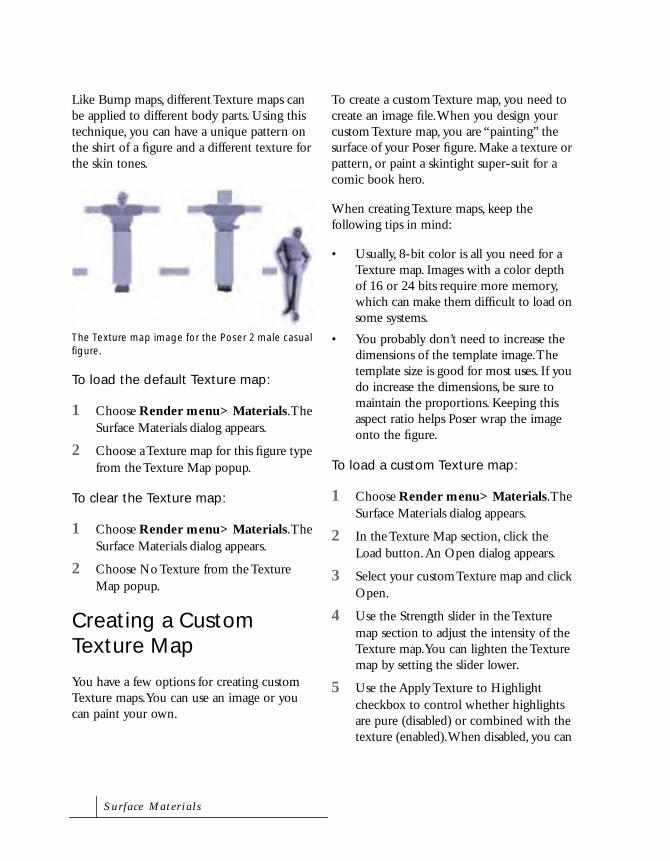
Like Bump maps, different Texture maps can be applied to different body parts. Using this technique, you can have a unique pattern on the shirt of a figure and a different texture for the skin tones.
To load the default Texture map:
1 Choose Render menu> Materials. The Surface Materials dialog appears.
2 Choose a Texture map for this figure type from the Texture Map popup.
To clear the Texture map:
1 Choose Render menu> Materials. The Surface Materials dialog appears.
2 Choose No Texture from the Texture Map popup.
Creating a Custom Texture Map
You have a few options for creating custom Texture maps. You can use an image or you can paint your own.
To create a custom Texture map, you need to create an image file. When you design your custom Texture map, you are “painting” the surface of your Poser figure. Make a texture or pattern, or paint a skintight super-suit for a comic book hero.
When creating Texture maps, keep the following tips in mind:
• Usually, 8-bit color is all you need for a Texture map. Images with a color depth of 16 or 24 bits require more memory, which can make them difficult to load on some systems.
• You probably don’t need to increase the dimensions of the template image. The template size is good for most uses. If you do increase the dimensions, be sure to maintain the proportions. Keeping this aspect ratio helps Poser wrap the image onto the figure.
To load a custom Texture map:
1 Choose Render menu> Materials. The Surface Materials dialog appears.
2 In the Texture Map section, click the Load button. An Open dialog appears.
3 Select your custom Texture map and click Open.
4 Use the Strength slider in the Texture map section to adjust the intensity of the Texture map. You can lighten the Texture map by setting the slider lower.
5 Use the Apply Texture to Highlight checkbox to control whether highlights are pure (disabled) or combined with the texture (enabled). When disabled, you can
The Texture map image for the Poser 2 male casual figure.
S u r f a c e M a t e r i a l s

get shiny spots on a black area of the texture.
Using Templates
If you did a complete install, templates are provided in Poser:Runtime:Textures. If you didn’t, the templates can be found on the Poser 4 Application CD-ROM.
Bump, Texture, Reflection, and Transparency maps are found in the Textures folder. The templates let you precisely align the image you paint with the figure.
The template provides Texture maps for every available part of a figure. They contain maps for everything from teeth to the shoe laces. By painting on the template, you can edit the color or pattern of a body part.
When you have modified the Texture map, save it as a PICT (Macintosh), TIF (Windows) or BMP (Windows) file. Put it in the Poser Textures folder for easy loading.
To load an edited Texture map template:
1 Choose Render menu> Materials. The Surface Materials dialog appears.
2 Choose the figure you want to edit from the Object popup.
3 Do one of the following:
• To apply a map to a specific part, choose a part from the Material popup.
• To apply the map to the entire figure, enable the Texture Changes apply to entire figure checkbox.
4 Click the Load button in the Texture Map section. An Open dialog appears.
5 Locate the edited template file and click Open. The texture is applied to the figure.
6 If you edited other body parts, choose the body part you want to change from the Materials popup.
7 Click the Texture Map Load button again and load the edited template file.
8 Continue selecting body parts and loading the template file, until all the body parts on your figure have the desired Texture map. The textures will appear when you render the scene.The Texture map template applied to a figure.
P o s e r 4

Applying Transparency MapsTransparency allows light pass through a figure or object, so you can see through it. The higher a transparency value, the more of the surrounding environment is visible through the object’s surface. If no light is reflected on an object, a 100% Transparency Min and Max makes it invisible.
Use transparency maps for interesting effects in your creations. For example, you can create ghost-like characters in a scene, with transparent bodies mapped with patterns or textures.
When a transparency map is applied to an object, its texture interferes with the transparency of the object. For example, a checkerboard map results in an object that is alternately transparent and solid. You can thus use textures as transparency maps.
To load a Transparency map:
1 Choose Render menu> Materials. The Surface Materials dialog appears.
2 Choose a Transparency map for this figure type from the Transparency Map popup.
To clear the Transparency map:
1 Choose Render menu> Materials. The Surface Materials dialog appears.
2 Choose No Transparency from the Transparency Map popup.
Creating a Custom Transparency Map
You have a few options for creating custom Transparency maps. You can use an image or you can paint your own. When creating Transparency maps, use an 8-bit, gray scale image; do not use color. The brightness of a map’s pixels is the only factor that matters, and an 8-bit image requires less memory.
To load a custom Transparency map:
1 Choose Render menu> Materials. The Surface Materials dialog appears.
2 Choose the figure you want to edit from the Object popup.
3 Do one of the following:
• To apply a map to a specific part, choose a part from the Material popup.
• To apply the map to the entire figure, enable the Texture Changes apply to entire figure checkbox.
4 In the Transparency Map section, click the Load button. An Open dialog appears.
5 Select your custom Transparency map and click Open.
The Transparency map applied to a sphere.
S u r f a c e M a t e r i a l s

Using the Transparency Sliders
The Transparency Min, Transparency Max, and Transparency Falloff sliders work together to determine how an object’s transparency behaves.
Transparency Min refers to the edges of the object facing away from the eye. A high Transparency Min value makes the object very transparent on its edges.
Transparency Max refers to the part of the object which points at the eye. A high Transparency Max value makes the object very transparent in the center facing the eye.
For most renderings, you’ll want to use a Transparency Max value that is higher than the Transparency Min value.
Transparency Falloff determines the rate at which the transparency becomes opaque on the edges of an object. For a real world example, look at a transparent object such as a drinking glass. The edges of the glass are less transparent than the rest of the surface. This is
where transparency of the glass “falls off ”. In Poser, you can vary this falloff behavior. A smaller value renders a smaller falloff band, while a larger value renders a wider band
If the Transparency Min and Max values are the same, there is no falloff in the rendering.
Applying Reflection MapsReflection makes a figure or object direct light back at its source, giving it a mirrorlike appearance. A Reflection map is a 2D texture applied to a virtual sphere that surrounds your studio. The texture is then reflected from the studio and onto your object.
Reflection maps can be applied to different objects and body parts. For example, you could create a space alien and apply a mirror-like reflection map to the head, or the entire body.
Lower and higher Transparency Min values.
Transparency Min at a higher value
Transparency Min at a lower value
Three different falloff rates.
A Reflection map applied to a figure.
P o s e r 4

To load a Reflection map:
1 Choose Render menu> Materials. The Surface Materials dialog appears.
2 Choose the figure you want to edit from the Object popup.
3 Do one of the following:
• To apply a map to a specific part, choose a part from the Material popup.
• To apply the map to the entire figure, enable the Texture Changes apply to entire figure checkbox.
4 Click the Reflection Map popup to choose a Reflection map.
5 Use the Strength slider in the Reflection map section to adjust the intensity of the map. The higher the value, the more reflective the surface. At 50%, half the light that hits the object is reflected. At 100%, all light is reflected.
6 Control the intensity of the reflection with these checkboxes:
• The Multiply through lights checkbox reduces the reflection’s intensity based on how the figure is lit by the lights. This is an easy way to add subtlety to the lighting.
• The Multiply through Object Color checkbox reduces the reflection’s intensity by multiplying its result through the object’s color. So, for example, a red object would get a reddish reflection instead of the raw color from the reflections map.
7 To add a Reflective Color, click its button. Choose a color from the color picker dialog, then click OK. The reflective color appears when you render the scene.
To clear the Reflection map:
1 Choose Render menu> Materials. The Surface Materials dialog appears.
2 Choose No Reflection from the Reflection Map popup.
Reflective Color
Reflective Color is a tint that is added only when a reflection map is applied. Use the Reflective Color control to create dramatic effects in your renderings.
To make a highly reflective object appear more vivid, use a variation of the object’s color. If the object’s color is particularly bright, you may want to use a darker tint of the same color. For an unusual tint, use a color that is distinctly different from the object’s color.
Creating a Custom Reflection Map
You have a few options for creating custom Reflection maps. You can use an image or you can paint your own.
When creating Reflection maps, keep these points in mind:
S u r f a c e M a t e r i a l s

• The image in a reflection map is applied to a virtual sphere and reversed when it is reflected on your object.
• For color reflection maps, the hue affects the tint of the reflection and the brightness determines the amount of reflection. Darker colors result in less reflection; brighter colors result in more reflection.
To load a custom Reflection map:
1 Choose Render menu> Materials. The Surface Materials dialog appears.
2 Choose the figure you want to edit from the Object popup.
3 Do one of the following:
• To apply a map to a specific part, choose a part from the Material popup.
• To apply the map to the entire figure, enable the Texture Changes apply to entire figure checkbox.
4 In the Reflection Map section, click the Load button. An Open dialog appears.
5 Select your custom Reflection map and click Open.
Setting ColorsThe color of a figure’s “skin” in a rendering is determined by the lighting environment and these surface material factors:
• Object color
• Highlight color
• Ambient color
• Reflective color
• The surface material map
These features apply to both figures and props.
Object Color
The object color is the surface color of the current figure or prop. If there is no Texture map, the object color is the only color of the figure—not considering the effect of colored lights. In a high quality rendering, when a Texture map is loaded, the object color influences the appearance of the Texture map by coloring it. If you don’t want the Texture map affected by the object color, set the object color to white (the default color is tan).
A custom Reflection map applied to a prop.
P o s e r 4

To set the object color:
1 Choose Render menu> Materials. The Surface Materials dialog appears.
2 Click the Object Color button. The color picker appears.
3 Choose a surface color for the object and click OK.
You can also set the object color using the Color tool. Refer to “Using the Color Tool” on page 139 for more information on the Color tool.
Texture Maps vs. Object Color
When a Texture map is loaded, the object color is used as a multiplier on the Texture map. What does this mean? The complete answer is rather technical. The result, however, is quite simple. The object color influences the Texture map in a rendering as though some of its pigment was washed over the Texture map image. How much of the pigment depends on the brightness of the object color—the lighter the object color, the less pigment is used. Therefore, when the object color is white, it has no effect on the Texture map whatsoever. When the object color is near black, it obliterates the Texture map; this effect is only apparent in renderings.
Highlight Color
Highlights are bright areas appearing where the light is reflected directly toward the eye—or camera. As Poser renders the figure, it determines where highlights should occur and adds the highlight color to the base color at these points.
In daylight and under most room lights, highlights are white. To complement the lighting environment you’ve set, select a color similar to your main light.
To select the highlight color:
1 Choose Render menu> Materials. The Surface Materials dialog appears.
2 Click the Highlight Color button. The color picker appears.
3 When you’ve chosen a color, click OK.
4 To control the size of the highlights, move the Highlight Size slider. The default value is 70%. Higher settings increase the size of the highlight, creating a dull effect. At 100%, the highlights overwhelm the figure. At 20%, the highlights are small, creating a shiny effect. At zero, with the highlight color set to black, no highlights appear
Setting highlight size.
S u r f a c e M a t e r i a l s

Ambient Color
In Poser, you can set the Ambient color for each figure or object individually. An object’s Ambient color is the color it emits equally in all directions. It simulates an ambient (overall room) lighting contribution. Unlike the other color properties, it acts without taking into account any light positions or colors.
The Ambient color mixes with the other lighting properties. Too much ambience flattens the detail of an object, since it looks the same no matter how the surface faces lights. If you want to turn ambient light down or off, set the Ambient color to gray or black. If you want more intense ambient light, set the Ambient color to white or a bright color.
To select the ambient color:
1 Choose Render menu> Materials. The Surface Materials dialog appears.
2 Click the Ambient Color button. The color picker dialog appears.
3 When you’ve chosen a color, click OK.
P o s e r 4

S u r f a c e M a t e r i a l s

12Rendering
How Rendering WorksRendering is the process of converting the 3D view of your figure into a 2D image. Once you render an image, you can use it in other image-editing applications.

During the course of a Poser project, you’ll want to render a number of times to check the progress of your pose, body shape, camera, surface material, or lighting changes.
Renderings show more detail, so you see things in a rendering that aren’t otherwise apparent. Based on these results, you’ll go back to posing, body shaping, etc., to adjust anything that needs improvement. You’ll probably go back and forth—making changes, then rendering to check your changes—several times.
A render mode called Antialias Preview Render lets you quickly generate an antialiased image that you can use to check lighting or surface materials. Refer to “Antialias Rendering” on page 263 for more on generating previews.
These “check” renderings are typically displayed in the Document window. You probably won’t save them. They’re just a by-product of the work process.
Finally, when you’ve made all the changes you want, you’ll generate a high-quality rendering that you will save—either by exporting the Document window as an image file or by rendering to a new window. Rendering an animation takes longer, depending on the number of frames it has.
Rendering an animation is similar to rendering an image; however, instead of creating one image, you create several—a separate image for each frame. Render an animation with Animation menu> Make Movie. This procedure is covered in “Rendering an Animation” on page 264.
Renderings do not include guides, with the exception of the Ground Plane. If you don’t want to show the Ground Plane, hide it before rendering.
Setting Up a RenderThe Render Options dialog lets you control the size and attributes of the final output rendering. Render Options include rendered image size, background color, antialiasing, shadows, and whether to apply surface materials, if any have been loaded.
A rendering in progress.
R e n d e r i n g

To display the Render Options dialog:
• Choose Render menu> Render Options. The Render Options dialog appears.
Setting Render Destination
By default, renderings appear in the Document window. Poser clears the image from the window as soon as you make an adjustment. This saves on memory and keeps your Desktop from getting cluttered with windows.
If you want renderings to go to a separate window, enable the New Window option. Future renderings of your scene appear in separate windows.
To set the render destination:
1 Choose Render menu> Render Options. The Render Options dialog appears.
2 Enable the New Window radio button if you want to open a new window for a rendering. Otherwise, enable the Main Window button and the rendering
replaces the image in the Document window.
Setting Image Size
When you render to a new window, you can set the window to any size.
If you’ve imported a background image, Poser automatically sets the new window to the dimensions of the background. This is handy when you’re planning to composite the figure with the background.
To render at a particular size:
1 Choose Render menu> Render Options. The Render Options dialog appears.
2 Enable the New Window radio button and enter the size you want.
You can specify the render size in either pixels or in inches. Use the popup to select the units you want.
3 Enter either the height or the width for the rendering; Poser automatically adjusts the other value to maintain the aspect ratio of the window.
The Render Options dialog.
NoteRenderings always use the
aspect ratio of the Document
window. If you want a different
aspect ratio, resize the
Document window.
P o s e r 4

Choosing a Rendering Background
By default, Poser renders to the Document window over the background color or imported background picture. When you render to a new window, you can specify which background is rendered with the window.
To choose a rendering background:
1 Choose Render menu> Render Options. The Render Options dialog appears.
2 In the Render Over section, enable one of the three radio buttons. The available options are:
Background color: The figure is rendered over the current background color. You can change the background using the color icons on the right side of the Document window or using the Color tool.
Black: The pixels on the edge of the figure are antialiased darker with a black background. This is the best option when you are planning to composite the figure with an image in another application.
Background Picture: Poser composites the rendering of the scene with the imported background image. This option is available only when you’ve imported a background image.
For more information on background pictures, refer to “Pasting Figures onto
the Background” on page 43 or “Importing and Exporting” on page 47.
Setting Surface Detail
The Surface detail section of the Render Options dialog provides options for rendering features. Disabling these features allows the rendering engine to work more quickly. In the final rendering, however, you’ll want all these features turned on.
To set surface detail:
1 Choose Render menu> Render Options. The Render Options dialog appears.
2 In the Surface detail section, click one or more of the options provided.The available options are:
Antialias blends the pixels along the edge of one area with the pixels along the edge
You can render over a background image to add interest.
R e n d e r i n g

of the adjacent area. This creates a softer, smoother edge.
Use Bump Maps and Use Texture Maps control whether these surface material features—if currently loaded—are used in the rendering. Transparency and Reflection maps are considered texture maps.
Cast Shadows controls whether Poser renders the light shadows. Shadows increase render time, so you may want to render without them if you’re in a hurry.
Rendering an Image
You can render an image using either the Render command or one of the preset rendering options. The Render command uses the options you set in the Render Options dialog to render your image, and should be used to render a final image. The preset rendering options temporarily override the Render Options parameters. They produce lower quality renders you can use to periodically check your work.
Using the Render Command
The Render command uses all the current settings in the Render Options and Surface Material dialogs.
To render a scene:
• Choose Render menu> Render. A status dialog appears letting you know the status of your render. When completed, a new rendered image appears in either the Document window or a separate window.
Antialias Rendering
The Antialias Document Render command temporarily overrides the features set in the Render Options and Surface Materials dialogs, and creates an antialiased image from the Document window. The image is created using the current display style and lighting. When you click the Document window, the antialiased image is replaced by the current display style.
To make an antialiased rendering:
• Choose Render Menu> Antialias Document.
Choose Antialiased to create a smooth, high quality rendering.
Aliased Antialiased
P o s e r 4

Rendering an AnimationYou can make a movie by rendering a Poser animation as a QuickTime or AVI movie file. Poser renders each frame of the animation to a frame in the output movie.
Typically, you’ll make a movie several times to check its smoothness and continuity. Each time, you can go back to your animation file and improve the keyframe settings. You can trash your test movies after viewing them.
Finally, when you’re satisfied with the entire animation, you’ll make the movie at its full resolution and render settings. This is the final product that you’ll save and open in a post-production program.
The figures in the final movie are masked in each frame. This makes it easy to composite the movie with other images.
Using the Make Movie Dialog
The Make Movie dialog contains all the controls you’ll need to set and render an animation.To make a movie:
1 Make sure the current camera is the one for which the animation was created.
2 Choose Animation menu> Make Movie. The Make Movie dialog appears.
3 Enter a name in the Movie field.
If you are saving to numbered files, Poser automatically appends 4-digit numbering to the file name.
4 Choose a format for the output movie from the Sequence Type popup.
• For viewing, use QuickTime or AVI. These formats are also suitable for saving a movie for other applications.
• For exporting to a motion graphics program, you may want to use numbered PICT (Macintosh), BMP or TIF files (Windows). This type of output allows you to save animations without any loss of data.
5 Choose Full, Half, or Quarter from the Resolution popup. The smaller the resolution, the faster the rendering, so you may want to use smaller resolutions for test movies.
Set the dimensions of the full sized frame in the Animation Setup dialog.
6 Choose the current display or render settings from the Quality popup.
If you choose Current Render Settings, verify that they are set as you want them before making the movie. Some options, like antialiasing, increase the rendering time.
Set movie options in the Make Movie dialog.
R e n d e r i n g

7 To turn antialiasing on, enable the Antialias checkbox
8 In the Frame Rate section, select one of the following options:
• To use the frame rate set in the Animation Setup dialog, enable Use Movie’s frame rate.
• To use a new frame rate, enable Use this frame rate, then enter a number. You can use a lower frame rate, which renders faster, for test movies.
Frame Rate does not apply to numbered files.
9 In the Time Span section, enter the Start and End time of your rendered animation. This sets the range of frames that are rendered as the final movie.
Poser calculates and displays the number of frames and duration of your selection.
Usually, you’ll use the entire set of frames. However, you can select a subset of frames to check a particular motion.
The Time Span display uses the standard SMTPE time code format (Hours: Minutes: Seconds: Frames).
10 Click OK to start the rendering. A Save dialog appears.
11 Choose a save location. If you’re saving to numbered files, you may want to create a special folder for them.
12 Click Save to proceed.
If you are saving to numbered files, the rendering begins.
If QuickTime or AVI is the selected sequence type, Poser displays the QuickTime Compression or MS Video
Compression options dialog. Choose compression options and click OK. This may take a little while.
Poser renders a frame and displays it in the QuickTime dialog so you can visually check compression quality.
For more information about QuickTime and AVI movie compression options, consult your operating system’s User Guide.
Using the Sketch DesignerPoser’s Sketch Designer renders scenes in a sketch style drawing. A scene is rendered using a series of black and white or colored brush strokes. You can tailor the strokes to your liking.
The Sketch Designer.
P o s e r 4

Renderings in the Sketch Designer can be saved and reloaded later. You can also export a sketch as a Painter script to create rendered images using the Painter brush libraries. Finally, you can create amazing animations which emulate traditional sketching techniques.
You’ll get the best results from the Sketch Designer when you render a scene with considerable detail (such as hair on a figure) and dramatic lighting.
The Sketch Designer Window
To use the Sketch Designer:
• Choose Window menu> Sketch Designer. The Sketch Designer window appears.
While a sketch is drawing in the window, you can click anywhere on the screen to stop the rendering.
You can customize the controls of the Sketch Designer window to create your own sketch styles, or you can choose from several styles in the Preset Styles popup.
The following sections describe the options that are available for creating a unique Sketch Designer.
You can animate sketching techniques with the Sketch Designer. The Sketch Designer window
R e n d e r i n g
Parts of the Scene
You can control the sketch style behavior of three parts of the scene:
• Click Stroke to edit the sketch style of any figures and objects in the scene.
• Click Background to edit the sketch style of the background.
• Click Edge to edit the sketch style of any figures and objects’ edges.
Sliders
You can customize your sketch with the slider controls. The sliders determine many characteristics of stroke lines. As you adjust each slider the sketch is redrawn, so you can see your results in real time.
Density controls the density of lines in the sketch.
Line Length defines the length of strokes.
Min Width defines the width of the edge of each stroke. This control affects the brightness of the original image.
Max Width defines the width of the center of each stroke. This control affects the brightness of the original image.
Lo Brightness determines the band of tone. A lower setting means lines are drawn only in the darkest parts of the scene. If the Over Black option is disabled, set this control to zero for the best results.
Hi Brightness determines the band of tone. A lower setting means lines are drawn only in the darkest parts of the scene. If the Over Black option is enabled, this control should be at 1, for best results.
Stroke Head determines the amount each stroke tapers at its head.
Stroke Tail determines the amount each stroke tapers at its tail.
Line Random a higher value randomizes the shape of the lines
Color Random a higher value randomizes the color of the lines
Opacity determines the clarity of lines. Lower values create more transparent strokes.
Cross Hatch controls the frequency of cross hatching in the strokes.
Total Angle determines the amount of angle change that the whole stroke can go around before it stops drawing the stroke. A higher value makes an image darker. When you set Density at a small value, set Total Angle at a smaller value.
Color Cutoff determines the threshold of color change allowed for a stroke. Use this slider in conjunction with Total Angle.
Light 1, 2, 3 determine how much each of the first three studio lights contributes to the direction of the strokes. A high value results in strokes going in the direction of the light.
BG Direction defines the direction of the background strokes.
P o s e r 4
Auto Spacing If Auto Density is enabled, this slider controls the amount of space between strokes
Color Blend controls the amount of color in the document window to be blended into the sketch.
Textured Brushes
You can choose between several texture brushes in the Sketch Designer window. The choices are Sharp, Bristles, Very Soft, Soft, Less Soft, and Slanted. You’ll find the effects of these brushes is most visible when you set the Min Width and Max Width sliders to higher values.
Sketch Designer Options
The checkbox options available in the Sketch Designer window are:
Over Black When enabled, the background is black and strokes are white. When disabled, the background is white, and strokes are black or colored.
Auto Density When enabled, the render reaches an automatic density based on the original image, and the Density slider setting is ignored. When this is disabled, use the Density slider.
Colored Strokes When enabled, figures and objects are rendered in color. When disabled, no colors appear.
Working with Completed Sketches
Once you create a sketch, you can save it to and delete it from the Preset Styles popup. In addition, you can export your sketches to Painter scripts.
To save a sketch:
1 Choose Create Preset from the Preset Styles popup.
2 Enter a name for your sketch. Poser automatically attaches a .pzs suffix to the filename.
To delete a sketch:
• Choose Delete Preset from the Preset Styles popup.
To export a sketch to a Painter script:
1 In the Sketch Designer, render the scene to your liking.
2 Choose File menu> Export> Painter Script.
3 Choose a save location and name the file.
R e n d e r i n g

Rendering a Sketch
After setting up a sketch, you can render it so that the sketch appears in your document window. You’ll find this feature useful if you want to export a movie in sketch style.
To render a sketch in the Document window:
• Choose Render menu> Sketch Style Render.
P o s e r 4

R e n d e r i n g


13Advanced Body Shaping
Besides the basic shaping tools discussed in Chapter 5 , “Body Shaping,” you can also customize the shape of figures using custom morph targets and the Joint Parameters palettes.

Creating Custom Morph TargetsAs discussed in “Using Morph Targets” on page 152, morph targets are transitional changes in the geometry of a figure that can be animated over time. Poser now includes a library of morph targets, and you can build your own morph targets in Poser as well.
In this section, you’ll learn how to build custom morph targets in other 3D modeling applications.
A morph target is a custom Parameter that is added to a body part so you can gradually reshape it. A figure’s geometry can move from the original shape of the model to the geometry of the morph target. During the course of an animation, the model begins to change shape until it reaches the morph target geometry.
Setting up Morph Targets
Morph targets are assigned to individual body parts. When you set up a Morph Target, a new Parameters Dial is added to the body part. The Parameter Dial lets you control the amount of morphing applied to the body part.
To add a morph target, you create a morph target geometry that represents the end-point of the morphing. The morph target geometry must contain the same number of vertices as the original body part, so it’s best to use the original body part as a starting point.
A Morph Target geometry can be created in any 3D modeling application that saves files in Wavefront (OBJ) format. The tutorial later in this chapter uses Ray Dream Studio 5 to create a Morph Target geometry. However, you don’t have to use Ray Dream Studio; any application where you can edit geometries and save files in OBJ format will work
To add a custom Morph Target:
1 Select the body part to which you want to add a morph target.
Choose Object menu> Properties. The Properties dialog appears.
2 Click Add Morph Target.
A Morph Target used to alter figure geometry.
Element Properties dialog.
A dva n c e d B o dy S h a p i n g

The Add Target dialog appears.
3 Click Locate to find the geometry file you want to use as a morph target. The file must meet all the following requirements:
• File must be in OBJ format.
• File must contain the same number of vertices as the original body part.
• File must contain only the body part you are morphing. Do not use a file of the entire figure.
The filename appears in the Geometry field.
4 Enter a name. The name appears on the morph target Parameter Dial for the selected body part.
5 Click OK to return to the Element Properties dialog. Click OK again to return to the main window.
A new Parameter Dial is added for the selected body part. Use this dial to morph the body part from its original shape to the morph target. A value of 0.0 for this dial is the original object. A value of 1.0 changes the body part to the morph target.
Morph Target TutorialThis tutorial uses Ray Dream Studio 5 to create a Morph Target for the head of a figure. You’ll make the nose grow like Pinocchio’s.
Lesson 1: Setting Up
To load a figure geometry into Ray Dream Studio 5:
1 Launch Ray Dream Studio 5.
2 Choose File menu> Open.
3 In the Open dialog that appears, click the Format popup and choose Wavefront.
4 Select the folder Poser 4: Runtime: Geometries: newMaleCasHi.
5 Select the file newMaleCasHi.obj and click Open.
6 Use the default settings for the OBJ import dialog and click OK.
Add Shape Interpolation Target dialog.
NoteImportant: For this tutorial to
work correctly, you must have
installed the new OBJ import/
export plug-in and mesh form
modeler for Ray Dream Studio
5.0.2, which is included with
Poser 4.
P o s e r 4

The figure loads into the perspective view and into the timeline with the name lFoot.
To edit the figure’s geometry:
1 Select the figure newMaleCasHi in the Timeline.
2 Click to select the figure in the perspective window, then choose Edit menu> Jump In.
3 Click the Selection tool.
4 Click away from the object to make sure there are no vertices selected.
5 Double-click in the figure’s head.
The entire head is selected. This may take a while.
6 With the head selected, choose Selection menu> Invert to select everything but the head.
The newMaleCasHi geometry, as shown in the Perspective window.
The newMaleCasHi geometry, shown in the mesh form modeler.
The newMaleCasHi figure with head selected.
A dva n c e d B o dy S h a p i n g

7 Press the delete key.
8 Click the Zoom tool.
9 Drag a marquee around the head.
10 To switch to the left view, choose View menu> Preset Position> Left. This makes the model easier to deform.
Lesson 2: Creating the Morph Target
To deform the geometry:
1 Click the Sphere of Attraction tool.
The default size, 4 inches, is too large for Poser figures. Compared to standard Ray Dream Studio units, Poser figures are very small. However, do not change the geometry size other than in the manner you want to morph it.
If, for example, you increase the size of the entire head, the size increase is included in the morph target. This is also true of the position relative to the center. In some cases, that may be the effect you
The body is deleted.
Enlarged view of the head.
Left view of head.
P o s e r 4
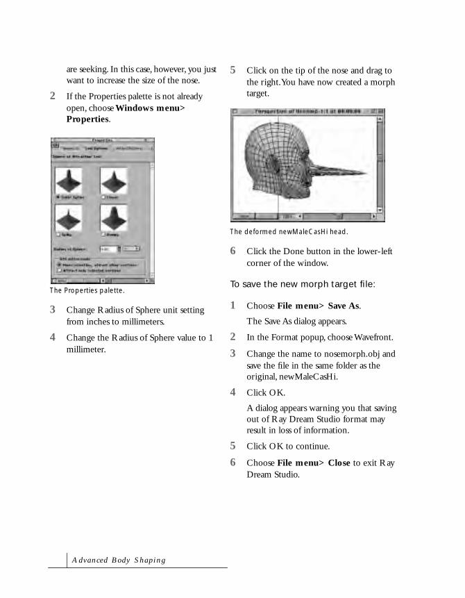
are seeking. In this case, however, you just want to increase the size of the nose.
2 If the Properties palette is not already open, choose Windows menu> Properties.
3 Change Radius of Sphere unit setting from inches to millimeters.
4 Change the Radius of Sphere value to 1 millimeter.
5 Click on the tip of the nose and drag to the right. You have now created a morph target.
6 Click the Done button in the lower-left corner of the window.
To save the new morph target file:
1 Choose File menu> Save As.
The Save As dialog appears.
2 In the Format popup, choose Wavefront.
3 Change the name to nosemorph.obj and save the file in the same folder as the original, newMaleCasHi.
4 Click OK.
A dialog appears warning you that saving out of Ray Dream Studio format may result in loss of information.
5 Click OK to continue.
6 Choose File menu> Close to exit Ray Dream Studio.
The Properties palette.
The deformed newMaleCasHi head.
A dva n c e d B o dy S h a p i n g

Lesson 3: Using the Target in Poser
To add a morph target in Poser:
1 Launch Poser.
2 From the Figures category of the Libraries palette, choose the People sub-category, if it’s not already selected.
3 Double-click the Casual Man preview.
The figure appears in the Document window.
4 Click the Face Camera icon in the Camera Controls.
5 Select the Head, and choose Object menu> Load Morph Target.
6 In the Add Target dialog that appears, locate and open the file Poser: Runtime: Geometries: newMaleCasHi: nosemorph.obj.
7 Enter “Nose” in the label field. This assigns the name “Nose” to the new Parameter Dial.
8 Click OK.
The People sub-category.
The Casual Man in the Document window.
The Face Camera icon.
P o s e r 4

9 Use the rotation trackball to rotate the view slightly to the left or right.
10 Click to select the Head.
11 Drag the Nose Parameter Dial to the right toward 1.0.
Your morph target is complete.
Figure Joints and Blend ZonesThe joints on a figure control how parts bend, blend, twist, and bulge. Realistic movement in a figure is controlled by joint settings. For example, a human knee joint can’t bend forward.
A figure’s bending and twisting motion is created using transformers. Transformers stretch, skew, or scale polygons in the transformation zones to produce desired joint motion.
The transformation zone is defined by the inclusion and exclusion angles assigned to each transformation. Polygons in the exclusion angle are not affected by a transformation, while polygons in the
A rotated view of the figure.
The morphed Nose.
An example of figure joints.
A dva n c e d B o dy S h a p i n g

inclusion angle are affected. In the area between the angles, or blend zone, polygons are adjusted to create a smooth transition between the surrounding polygons.
Joints are controlled using the Joint Parameters palette. Blend zones are edited each time you adjust the transformation inclusion and exclusion angles. Blend zones can be further refined using Spherical Falloff zones.
Editing Joint Parameters
The Joint Parameters palette lets you control both joints and blend zones. You can directly manipulate joints and blend transformers to set how a joint works. These advanced settings can be used to:
• Fine tune the bending of existing figures to suit your needs
• Create new types of effects, such as imitating ‘Mr. Fantastic’ from the Fantastic Four comics
• Customize joints and transformers for creating your own new figures
Refer to “Creating Custom Figures” on page 301 for more information on creating Poser figures.
Each joint on a figure has a set of attributes, like Bend, Twist, or Side-to-side. The attributes available for editing depend upon which joint is selected. Editable attributes are displayed in the popup at the top of the palette.
To edit a joint’s parameters, you first select a joint attribute and then set each of its parameters. Each attribute has a specific set of parameters that control how the attribute affects the joint. For example, the parameters for the Center attribute let you control the exact position of the center point. An example of blend zones.
NoteBefore making any changes to
a Joint Parameter, turn all IK
Chains off. It is also easier to
see some attributes, such as
the center, if you view them in
outline or wireframe display
mode. If your computer is fast
enough, use Full Tracking to
see the results of your changes
in real-time.
P o s e r 4

To display the Joint Parameters palette:
• Choose Window menu> Joint Editor.
The controls available on the Joint Parameters palette depend on the currently selected body part or prop.
To edit a joint parameter:
1 Select a body part.
2 Display the Joint Parameters palette.
3 Select an attribute from the popup at the top of the palette.
4 Set the attribute’s parameters.
Using the Joint Parameters Palette
The Joint Parameters palette contains several controls to set attributes for a joint. Although the controls change for different body parts, the controls common to all body parts are:
Display Deformer: Toggles the graphical display of the joint on a figure.
Zero Figure: Resets to 0 the rotation (Bend, Twist, Side-Side, Front-Back) for all body parts.
Use Spherical Falloff Zones: Toggles on or off the Spherical Falloff Zones on a figure. Refer to “Spherical Falloff Zones” on page 287 for more on falloff zones. The Use Spherical Falloff Zones control appears on all attributes except the Center attribute.
Interactively Editing Joint Parameters
When you select a joint attribute from the popup in the Joint Parameters palette, a graphical representation of the parameter appears on a figure. For example, when you select the Twist attribute for the leg, a red and green line appears on the leg.
Center
A body part’s center becomes the outline of the selected target when you can edit it.
The Joint Parameters palette.
Attribute popup
A dva n c e d B o dy S h a p i n g

Twist
When you select the Twist attribute, a line with two handles appears on the figure. The red handle represents the starting point of the twist transformation area, and the green handle represents the end. Dragging these handles increases or decreases the Twist area.
Editing Inclusion and Exclusion Angles
When using Bend or Side-Side/Front-Back, the red lines represent the exclusion angle, while the green lines represent the inclusion angle.
Polygons in the exclusion angle are not affected by a transformation. Polygons in the inclusion angle are affected by the transformation. The area between the inclusion and exclusion angles is the Blend zone.
To edit inclusion and exclusion angles:
1 Move the cursor to an end point of the exclusion or inclusion angles until the cursor changes to a target symbol.
2 Drag the angle. If you’re using full tracking, the effects of your change are shown as you drag.
Inclusion and exclusion angles exist in three dimensions, so you can rotate a figure to see all the areas affected by the transformation. You can also edit angles in all three dimensions.
To make sure you’re moving an angle in only one dimension, use the orthogonal cameras. For example, using the From Front camera, moving left and right moves in x. Moving up and down moves in y. With the From Left view, left and right move in z, and up and down move in y.
Bend
To adjust the Bend transformation area, drag the end-points of the red or green angle. To change the center of the body part, drag the center point target.
Side-Side/Front-Back
Like the Bend attribute, both the Side-Side and Front-Back attributes are edited by dragging the inclusion and exclusion angle lines.
A Twist attribute displayed graphically on the figure.
P o s e r 4

Joint Attributes
Each joint on a body part has a number of parameters that together control how the joint moves.
Center
The Center Attribute sets the center of rotation for a selected body part. This attribute is available for all body parts and props.
The parameters of the Center attribute are:
Center Point: Sets the XYZ position of the center of the body part. 0,0,0 is located in the center of the body on the floor.
Orientation: Sets the XYZ rotation of the axis. Click and drag a dial to rotate the axis. Option/Alt-click a dial to reset it to 0.
Align: Aligns the axis to the rotation of the body part.
Twist
The Twist attribute alters the location of the twist transformer for each body part. The intensity of the transformation is controlled using the Twist Parameter Dial or Twist tool.
There is not a Twist attribute for the hip, since it is the parent of the entire figure. Twisting the parent is the same as rotating the entire figure. When IK is enabled, twisting the hip transforms body parts included in the IK chains.
The Center attribute.
The Twist Attribute.
A dva n c e d B o dy S h a p i n g

By default, the Twist axis runs lengthwise down the center of each body part. For example, for arms, the twist axis is the x-axis, while for legs the twist axis is the y-axis. Moving and rotating the center of a body part can alter the position of this axis.
The parameters of the Twist attribute are:
Twist Start, Twist End: Sets the start and end of a twist area on a body part. Only the body parts in the twist area are affected by the twist transformation.
Twist areas can be made larger than the body part to make a twisting motion appear more natural. In most cases, you want to include the body part’s parent.
Bend
The parameters for the Bend attribute alter the angles of the bend transformers and define how bulges are created.
The parameters of the Bend attribute are:
Center Point: Sets the XYZ position of the center of the body part. Bending occurs at the center point. Changing that point changes the center of the body part.
Joint Angles: Set inclusion and exclusion angles for the Bending transformation. The values in Static A and D together set the exclusion angle. Polygons in the exclusion
The Twist axes on the body.
The Bend attribute.
P o s e r 4

angle are not affected by the bending. The values in Dynamic B and C together set the area of inclusion. Polygons in the inclusion angle are affected by the bending.
Apply Bulges: When enabled, these parameters control how polygons in the bend zone are stretched or pinched to create bulges or wrinkles. Right and Left dials refer to the sides of the figure. Neg and Pos dials refer to negative or positive values for the rotation of the attribute (for example, a positive value for the Bend attribute creates bulges as set by the Right and Left positive bulge dials). Option/Alt-click these dials to reset them to 0.
Side-Side/Front-Back
The parameters for the Side-Side/Front-Back attributes control angles of the Side-Side/Front-Back transformers and define how bulges are created.
The angles of inclusion and exclusion on a body part.
Differences in bulges and wrinkles when the body part center is changed.
The Side-Side attribute.
A dva n c e d B o dy S h a p i n g

The Side-Side/Front-Back attributes have the following parameters:
Center Point: Sets the XYZ position of the center of the body part. Side-Side transformations occurs at the center point.
Joint Angles: Set inclusion and exclusion angles for the Side-Side transformation.
Apply Bulge: When enabled, these parameters control how polygons in the Side-Side transformation zone are stretched or pinched to create bulges or wrinkles.
Scaling
Each body part has parameters that let you scale the parent and child body parts. The settings are similar to the Twist parameters, and follow the Twist axis of the child or parent body part.
For example, the Right Collar of the Business Man has scaling controls for the chest (the parent body part) along the y-axis, and scaling controls for the Right Shoulder (the child body part) along the x-axis.
High End/Start, Low Start/End: The High and Low parameters define a blending area. For example, when scaling the head you may also want the top of the neck to scale.
When setting this parameter, only one pair of settings—the high or the low setting—is relevant. The unused parameter pair is automatically set to an out-of-limit number
The Front-Back attribute.
The Scaling attribute.
P o s e r 4

(such as 100.000 or 99.000). This indicates that the pair is not relevant to the area you have selected for blending. The out-of-limit settings should not be edited.
The end of each blending zone is represented in red, while the start is represented in green. The effects can be uniform, or can be controlled by spherical falloff zones. Refer to “Spherical Falloff Zones” on page 287 for more information.
Copying Joint Parameters
You can copy joint parameters from one half of a figure to the other using the Symmetry command.
To copy joint parameters:
1 Choose Figure menu> Symmetry> choose an option. A dialog appears asking if you want to copy the joint zone’s setup also.
2 Click Yes to include joint parameters.
Saving Joint Parameters
Changes to joint parameters affect only the current scene. To save joint parameter changes, you must either save your scene, or save the figure in the Libraries palette. Refer to “Saving to the Libraries Palette” on page 34 for details on saving figures to the Libraries palette.
The effects of High/Low scaling.
A dva n c e d B o dy S h a p i n g

Spherical Falloff Zones
Spherical Falloff Zones are an advanced method for controlling blending between body parts. Two spheres, a green “inner” sphere and a red “outer” sphere represent the falloff zones.
The green sphere defines the area that is 100% affected by the transformation. The red sphere represents the boundary of the transformer’s effect. The area between the inner and outer sphere is the “blending” zone. The effects of the transformation gradually decrease from 100% at the boundary of the inner sphere to 0% at the boundary of the outer sphere.
When adding Spherical Falloff Zones, the default position of the sphere is 0,0,0.
Displaying Spherical Falloff Zones
Spherical Falloff Zones can be selected and displayed using any display mode. To change the display mode for a sphere, select Element Styles from the Display menu, then select a mode. The default display mode for these spheres is outline.
Wireframe mode lets you view the spheres in 3D and still see the body parts they surround.
Editing Spherical Falloff Zones
Spherical Falloff zones can be edited using any of the Edit tools. You can reposition, scale, rotate, or twist Spherical Falloff zones.
Spherical Falloff Zones.
A Spherical Falloff Zone viewed in Wireframe mode.
P o s e r 4

A dva n c e d B o dy S h a p i n g

14Hierarchies
How Hierarchies WorkIn order to display a figure in the Workspace, Poser must interpret information about the figure’s geometry and body part parameters. This information allows Poser to create bendable joints between parent and child objects.
A scene’s hierarchy describes the parent-child relationships of all objects in the scene. Body parts or props that are physically located at a seam are generally contained either in a parent object or a child object. Data like rotation order and IK relationships are also defined in the scene’s hierarchy.
A Poser document hierarchy contains:
• A list of everything in the scene’s universe, including figures, body parts, props, lights, and cameras

• Hierarchical connections (parent-child relationships) for scene objects
• Parameters, including rotation, translation, Morph Targets, and Point At parameters.
• Any Inverse Kinematics (IK) chains of a figure
In Poser 4, you can work directly with a scene’s Hierarchy. The Hierarchy Editor displays everything in your Poser scene—all the figures, lights, cameras, and props currently in the studio.
With the Hierarchy Editor, you can:
• Select elements in your scene. When you select an item in the Hierarchy Editor, it is selected in the Document Window, Objects List, and Graph Palette.
• Double-click on an object to bring up its Object Properties.
• Set element visibility. Quickly hide body parts, props, or deformers.
• Rename or delete elements and parameters such as morph targets or Point At parameters.
• Set up or change parent-child relationships for props.
• Set up Inverse Kinematics (IK) chains.
• Change rotation order for props or body parts.
• Create new figures. Refer to “Creating Custom Figures” on page 301 for more information.
Using the Hierarchy EditorThe Hierarchy Editor displays a hierarchical listing of everything in your Poser document’s universe. You can contract this list to show only the parent elements in your scene, expanded elements to show their children, and expand objects to display their parameters. Depending upon what you want to select or modify, you can display it in the Hierarchy Editor.
To display the Hierarchy Editor:
• Choose Window menu> Hierarchy Editor. The Hierarchy Editor appears.
Using the Hierarchy Editor, you can easily expand/collapse scene elements.
H i e r a r c h i e s

Controlling what is Displayed
You can control what displays in the Hierarchy Editor by selecting display options at the top of the Editor. Options indicate what type of scene objects are in the hierarchy view.When the Hierarchy Editor first opens, a default set of options are checked.
To set the Hierarchy Editor display:
1 Choose Window menu> Hierarchy Editor to display the Hierarchy Editor.
2 Click a display option to display or not display certain scene elements.
An X appears in the box beside a selected display option.
Display options are:
• Show Figures: display all figures in the document
• Show Cameras: display all cameras
• Show Parameters: display object parameters
• Show All Parameters: display all parameters, as well as a few special scene level elements, like inner and outer scene boundaries
• Show Props: display all props in the scene, including the ground plane
• Show Deformers: display Magnets, waves, and Morph Targets
• Show Lights: show all lights in the scene
Collapsing the Hierarchy Editor
Scenes contain scene elements, including body parts, props, deformers, cameras, and lights. This can make for a very long Hierarchy Editor listing. You can collapse elements in the list to save space or expand them to show more detail. When not working with a particular figure, you can collapse its listing. This shortens the Hierarchy Editor list and makes other objects easier to locate.
To collapse/expand a listing:
1 Choose Window menu> Hierarchy Editor to display the Hierarchy Editor.
2 Click the minus icon next to an object to collapse it. The icon changes to a plus when the element is collapsed.
3 Click the plus icon next to an object to expand it. The icon changes to a minus when the element is expanded.
Use the display options at the top of the Hierarchy Editor to control what is displayed.
P o s e r 4

Selecting Objects
You can select an object in the Hierarchy Editor. Selecting an object here is equivalent to selecting it in the Document Window, choosing it in the Current Element pop-up at the bottom of the Document window, or selecting it in the Graph or Animation palette.
To select an object in the Hierarchy Editor:
1 Choose Window menu> Hierarchy Editor to display the Hierarchy Editor.
2 Click the object you wish to select.
As you select an object, notice that it is now also selected in the Document Window.
Deleting Objects
You can delete figures, props, and lights in the Hierarchy Editor. You cannot delete Poser figure body parts, cameras, or the ground.
You can delete Morph Targets and Point At parameters in the Hierarchy Editor. You cannot delete other object parameters.
To delete objects in the Hierarchy Editor:
1 Choose Window menu> Hierarchy Editor to display the Hierarchy Editor.
2 Select the object you want to delete.
3 Press the Delete/del key to delete that object.
To delete a group of objects in the Hierarchy Editor:
1 Choose Window menu> Hierarchy Editor to display the Hierarchy Editor.
2 Select the objects you want to delete.
Click on an object to select it.
NoteYou cannot delete just a body
part. If you select and delete a
body part, it deletes the entire
figure, just as it would in the
Document Window.
H i e r a r c h i e s

Renaming Objects
You can rename objects, making it easier to identify specific body parts and props.
To rename an object:
1 Choose Window menu> Hierarchy Editor to display the Hierarchy Editor.
2 Double-click on the name of the object that you want to rename.
3 Type in a new name for the object.
Reordering Objects
Figures
You can reorder props and Deformers in the Hierarchy Editor. Reordering Deformers can be useful, especially when they appear at the bottom of the Hierarchy listing. You cannot establish new parent-child relationships for Poser figure body parts.
You can reorder morph targets and rotation parameters (yrotate, zrotate, xrotate) for figure body parts. Rotation order affects how a body part twists or bends. By default, Twist is the top rotate parameter.
Props, Deformers, Lights, and Cameras
You can move Deformers and Morph Targets in the Hierarchy Editor.
You can reorder prop rotation parameters. Rotation order affects how a prop twists or bends. You can also do translations for props. Because the order in which rotation parameters are interpreted is important, be careful should you decide to reorder them.
You can reorder prop, light, or camera Point At parameters. These parameters also appear at the bottom of the Hierarchy Editor list.
NoteBe extra careful should you
decide to change rotation order,
because you can get unexpected
results.
Rotation parameter order affects how figure body parts twist and bend.
P o s e r 4

Displaying Object PropertiesYou bring up the properties dialog for an object right from the Hierarchy Editor. Accessing object properties from the Hierarchy Editor can be a real time saver.
To bring up the properties dialog from the Hierarchy Editor:
1 Choose Window menu> Hierarchy Editor to display the Hierarchy Editor.
2 Double-click an object in the Hierarchy Editor listing to display its Object Properties.
Changing Object VisibilityYou can change object visibility in the Hierarchy Editor. When you change object visibility in the Hierarchy Editor, it’s the same as changing it in the Object Properties dialog for that object.
Changing object visibility right in the Hierarchy Editor can also be a great time saver. It’s a great way to hide Magnet Deformers from view while you inspect the results of the Deformer. Changing object visibility is also a fast way to hide body parts. For example, when you load Poser 4 clothing into a scene, it may be necessary to hide some body parts so that they don’t show through the clothing. This is especially true for tight-fitting clothing. With the Hierarchy Editor, you can quickly make body parts invisible.
To change object visibility:
1 Choose Window menu> Hierarchy Editor to display the Hierarchy Editor.
2 Click the Eye icon next to the object to toggle visibility on and off. When the Eye is grey, the object is invisible.
To change visibility for a group of objects:
1 Choose Window menu> Hierarchy Editor to display the Hierarchy Editor.
2 Press Opt/Alt while you click the Visibility Eye for an object. This turns Double-click on an object to display Object
Properties for that object.
H i e r a r c h i e s

visibility on/off for that item and all its children objects.
Establishing Hierarchical RelationshipsA figure in Poser 4 is essentially a 3D model that has separate parts for each moving body part. What makes a Poser model unique is how it interacts with the controls in Poser. A 3D model in Poser has joints that move realistically, as in a real person.
Poser mirrors real body movement by adding joint parameters to each body part. This allows you to manipulate the figure based on those parameters. You can then create realistic motion, using Parameters Dials or the Walk Designer.
You can change parent-child relationships between the figures you’ve created and set up parent-child relationships for props. You cannot, however, reorder or change parent-child relationships for Poser figures. Refer to “Creating Custom Figures” on page 301 for more about creating new figures. Refer to “Establishing Hierarchical Relationships” on page 295 for more about setting up parent-child relationships.
When you bring a geometry into Poser, the Hierarchy Editor displays a Universe, followed by a list of props. Scene hierarchy relates what should move with what, i.e., children move when their parent moves.
When you create a figure from the geometry, Poser uses hierarchy information, to create joints necessary for figure posing. Unless the figure was created using standard body group names, you’ll have to manually establish parent-child relationships and establish a hierarchy order. Refer to “Applying the Standard Hierarchy” on page 299 for more about applying the Standard Hierarchy to figures created with standard group names.
Opt/Alt click the Visibility Eye for an object to reset visibility for that object and all objects indented under it in the Hierarchy Editor list.
NoteYou see changes in child/parent
relationships when IK is On verses
when IK is Off.
P o s e r 4

To create a parent-child relationship:
1 Choose Window menu> Hierarchy Editor to display the Hierarchy Editor.
2 Drag the intended child prop onto the root object, that is, the intended parent.
A white box highlight surrounds a valid parent object when the child object is correctly positioned on top of it. In addition, the mouse cursor indicates when it is OK to drop an object.
3 Release the child object when the box highlights the intended parent object.
To reorder objects at the same hierarchical level:
1 Choose Window menu> Hierarchy Editor to display the Hierarchy Editor.
2 Select the prop object you want to reorder.
3 Drag the object to the desired level.A box highlight surrounds the intended parent object when the child object is correctly positioned.
The Hierarchy Editor after dropping the child object onto the intended parent object.
H i e r a r c h i e s

A line is displays immediately before/after the target object, indicating where the object will be inserted.
4 Release the object to insert it in its new position.
A line is displayed immediately before/after the target object, indicating where the object will be inserted when dropped.
After moving an object to the same hierarchical level as the target object.
P o s e r 4

Creating Multi-Figure HierarchiesWhen posing more than one figure, you may want to tie the movement of one figure to another figure. You accomplish this by setting up a parent-child relationship.
For example, if you pose a female figure on a horse, you can make the female figure a child of the horse. This way, when the horse (the parent) moves, so does the female figure (the child).
You can attach the child to the entire parent figure or to just a portion of it. Continuing with the example, you can make the female figure a child of the whole horse or just the horse’s abdomen.
Once a parent-child relationship is set up, any rotation, translation, or twisting performed on the parent figure also applies to the child figure or prop.
To set up a multi-figure relationship in the Hierarchy Editor
1 Choose Window menu> Hierarchy Editor to display the Hierarchy Editor.
2 Select the figure you want to use as the child.
3 Drag the body of the child figure onto the intended parent. A box highlight indicates a valid drop location.
To set up a multi-figure relationship outside the Hierarchy Editor:
1 Click the Current Figure pop-up beneath the Document window and choose the figure you want to use as the child.
2 Click the Current Element pop-up and choose Body to select the entire figure.
3 Choose Figure menu> Set Figure Parent. The Set Parent dialog appears.
4 Select the body part from the hierarchy selection in the Set Figure Parent dialog.
5 Click OK to close the dialog.
Set up a parent-child relationship so figures can be posed together.
H i e r a r c h i e s

Applying the Standard HierarchyIt doesn’t matter how you create the geometry for a new figure. You can create it in Poser by grouping and saving groups as new Poser props. You can create individual figure parts in another software application and join them together in the Hierarchy Editor.
Regardless of how the geometry was created, when you introduce it into Poser, the Hierarchy Editor displays a Universe, followed by a list of props or a single prop with groups.
If, however, you created your figure geometry using standard body group names for human/bi-ped figures, you can use the Hierarchy Editor to automatically apply the Poser Standard Hierarchy to your figure. Applying the Standard Hierarchy establishes parent-child hierarchy in one pass. Poser can apply the Standard Hierarchy to full or partial figures. Refer to “Naming Groups” on page 306 for more about creating figures with standard body group names.
To apply the Poser Standard Hierarchy to a figure:
1 Choose Window menu> Hierarchy Editor to display the Hierarchy Editor.
2 Select the Universe.
3 Click the Apply Standard Hierarchy button.
Applying Standard Rotation OrderIf the props for human/bi-ped figures use standard body part names, Poser can automatically apply the standard rotation settings for each prop.
To apply standard rotation to a figure:
1 Choose Window menu> Hierarchy Editor to display the Hierarchy Editor.
2 Select Universe.
3 Click the Apply Standard Rotation Order button to apply the standard Poser rotation settings to body parts.
Setting Inverse KinematicsKinematics is the study of motion, velocity, rotation, and position. In terms of jointed structures, like an arm or leg, forward kinematics calculates how actions at the root of the structure affect the position and
NoteThe Apply Standard Hierarchy
button is not available unless the
universe is selected.
Using the Apply Standard Hierarchy button in the Hierarchy Editor automatically maps the parent-child relationships for your figure.
P o s e r 4

rotation of those at the end. For example, when you raise your arm, your hand automatically moves to a new position and rotation.
Inverse Kinematics (IK) uses the same kind of dependency, but in reverse. The extremity moves, and IK determines how the objects joined to it (closer to the root) responds to support the new placement. For example, if someone was to grab your hand and push, your arm would automatically bend at the elbow, while your shoulder would stay fixed in position.
Poser supports IK for any limb. When IK is on, you can translate the hands and feet and achieve appropriate arm and leg positions automatically. In Poser 4, you can create and delete new IK chains, using the Hierarchy Editor.
To turn IK off for a chain:
1 Choose Window menu> Hierarchy Editor to display the Hierarchy Editor.
2 Uncheck the IK On/Off checkbox to turn IK off for that chain.
You can also turn IK Off with the Figure menu> Use Inverse Kinematics command.
To create an IK chain:
1 Choose Window menu> Hierarchy Editor to display the Hierarchy Editor.
2 Select IK chains, to enable the Create New IK Chain button.
3 Click the Create New IK Chain button.
4 Enter a name for the new IK Chain.
A blank IK chain is added to the figure’s IK chains.
5 Drag individual body parts from the figure you’re creating onto the new blank IK chain.
6 Add nodes to the IK chain in the order of root to goal, the goal being the terminating node. For example, in the arm IK chain, the hand is the chain’s goal.
NoteIt might be helpful to turn Inverse
Kinematics Off for all existing
chains before setting up IK chains
in the Hierarchy Editor.
H i e r a r c h i e s

15Creating Custom Figures
Almost any geometry made up of polygons can be used as a figure in Poser. When you create a figure, its appearance has no effect on how it functions in Poser. It doesn’t even have to look human.
You can create your own Poser figures, using a variety of techniques. You can:
• Modify existing figures, then save them to the Figure Library
• Combine multiple existing figures into a new one.
• Combine props created with the Grouping tool that you’ve stored in the Props Library
• Create figure geometry in a 3D software application, like MetaCreations Ray Dream Studio, then use the Hierarchy Editor to set up figure Hierarchy information.
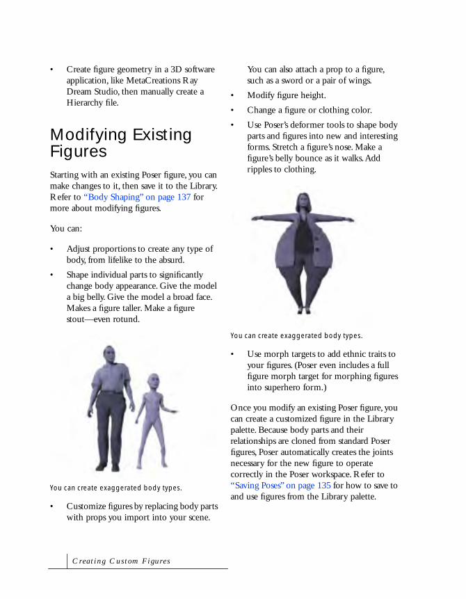
• Create figure geometry in a 3D software application, like MetaCreations Ray Dream Studio, then manually create a Hierarchy file.
Modifying Existing FiguresStarting with an existing Poser figure, you can make changes to it, then save it to the Library. Refer to “Body Shaping” on page 137 for more about modifying figures.
You can:
• Adjust proportions to create any type of body, from lifelike to the absurd.
• Shape individual parts to significantly change body appearance. Give the model a big belly. Give the model a broad face. Makes a figure taller. Make a figure stout—even rotund.
• Customize figures by replacing body parts with props you import into your scene.
You can also attach a prop to a figure, such as a sword or a pair of wings.
• Modify figure height.
• Change a figure or clothing color.
• Use Poser’s deformer tools to shape body parts and figures into new and interesting forms. Stretch a figure’s nose. Make a figure’s belly bounce as it walks. Add ripples to clothing.
• Use morph targets to add ethnic traits to your figures. (Poser even includes a full figure morph target for morphing figures into superhero form.)
Once you modify an existing Poser figure, you can create a customized figure in the Library palette. Because body parts and their relationships are cloned from standard Poser figures, Poser automatically creates the joints necessary for the new figure to operate correctly in the Poser workspace. Refer to “Saving Poses” on page 135 for how to save to and use figures from the Library palette.
You can create exaggerated body types.
You can create exaggerated body types.
C r e a t i n g C u s t o m F i g u r e s

Combining Multiple FiguresStarting with an existing Poser figure, you can make changes, then save parts of that modified figure in the Library. For example, you can save several types of heads, arms, legs, and torsos, just for use in creating future figures. Refer to “Saving Poses” on page 135 for more about using the Select Subset option when you’re saving figures.
To combine multiple figures into a new figure:
1 Load the figures you wish to combine into your Poser document.
2 Choose Window menu> Hierarchy Editor to display the Hierarchy Editor.
3 Set up parent-child relationships to establish the new figure’s Hierarchy. Refer to “Using the Hierarchy Editor” on page 290 for more about using the Hierarchy Editor to create figure hierarchies.
4 Click the Create Figure button on the Hierarchy Editor.
If the figures you’ve combined use standard Poser body parts, Poser follows the Hierarchy you’ve established to automatically create the joints necessary for the new figure to operate correctly in the Poser workspace.
Combining PropsYou can use the Grouping tool to select specific polygons on a figure or prop. With this feature, you can create new props. For example, you could start with the ball or cube props, modify them, then save a series of props that, when combined, create a robot body. Refer to “Using the Grouping Tool” on page 157 and “Adding Props to the Library” on page 175 for more details.
Using the expanding/contracting Hierarchy Editor, you can create new figures.
P o s e r 4

To combine props into a new figure:
1 Load the props you wish to combine into your Poser document.
2 Position the props to form the new figure.
3 Choose Window menu> Hierarchy Editor to display the Hierarchy Editor.
4 Set up parent-child relationships to establish the new figure’s Hierarchy. Refer to “Using the Hierarchy Editor” on page 290 for more about using the Hierarchy Editor.
5 Click the Create Figure button on the Hierarchy Editor.
Poser follows the Hierarchy you’ve established to create a new figure. Once created, you can use the Hierarchy Editor to fine-tune rotation order, so that body parts twist and bend as desired.
Creating Figures using other SoftwareYou can create your own Poser figure, using another 3D software program, like MetaCreations Ray Dream Studio. When you create figures outside of Poser, creation is a multi-step process.
Deciding how to Start
Before you begin to create articulated, bending figures in Poser, you need to make the following decision.
You can:
• Follow specific naming rules for body groups, then use the Hierarchy Editor in Poser to automatically apply standard Hierarchy and rotation order to your figure.
• Use non-standard (or a combination of standard and non-standard) naming for body groups and use the Poser Hierarchy
Use the Grouping palette to create your own props.
The Hierarchy Editor Create Figure button.
TipIn addition to parent-child
relationships, the Figure menu>
Point At command can be useful
for controlling the movement of
individual body parts in a robot
figure.
C r e a t i n g C u s t o m F i g u r e s
Editor to manually establish a figure Hierarchy
• Use non-standard (or a combination of standard and non-standard) naming for body groups, then create a figure Hierarchy as a text file and convert it for use as a Poser figure Hierarchy
Regardless of what you decide, the figure you create must be set up properly and stored in the correct format. That done, you can move or pose the model, just as you would any of the models included with Poser. With the right setup, you can make anything from an accordion to a zebra into a poseable figure.
Understanding the Process
To create a poseable figure, follow these steps.
• Create a 3D model of the new figure.
• Use the Poser File menu> Import commands to bring the contents of your 3D figure file into the current document.
• Use the Hierarchy Editor to create a Hierarchy file for the figure (or create a Hierarchy file as a text file and convert it to a Poser Hierarchy file).
• Adjust any joint parameters of body parts that twist or bend incorrectly.
• Set any necessary body part limits.
• Use the Hierarchy Editor to set up Inverse Kinematics (IK) chains.
• Set surface materials for the figure.
• Add any desired morph targets for adjusting the size and shape of body parts.
• Save the new figure to the Libraries palette.
Determining Model Format
In order to use figure geometry in Poser, you must store it in a Wavefront (OBJ) compatible format. With Poser 4, you can import model files in DXF, BVH, 3DMF, Wavefront OBJ, 3D Studio (Windows), and Painter3D (Detailer text) formats.
When creating your model, use only polygons. Nurbs or spline surfaces will not translate correctly.
Grouping Body Parts
Poser uses group names to identify body parts. Some Poser features, like the Walk Designer, require specifically named body parts. The group name is also the default name for working with this body part (you can change that at a later time).
It is important to denote the individual moving sections. You can store body parts as individual OBJ files or save the entire figure as a single file. With either method, plan carefully how you separate polygons into individual moving parts.
P o s e r 4

You don’t need to move these parts to the origin individually. You should leave them where they naturally relate to one another. Set up local origins later, inside Poser.
When you store the entire body in one file, you must use “groups” to separate different parts of the body that represent the moving Hierarchy. Saving the entire body in one file is usually the preferred method.
It is very important not to overlap groups. Wavefront grouping allows polygons to be in more than one group. If this happens, the overlapping polygons are duplicated when you bring the file into Poser and each group is turned into a separate Poser body part. For example, if you build a human-like object, you need to separate model polygons into the following groups:
• rHand
• lHand
• head
• neck
• lCollar
• rCollar
• chest
• abdomen
• hip
• rThigh
• lThigh
• rShin
• lShin
• rFoot
• lFoot
• rShldr
• lShldr
• rForeArm
• lForeArm
In order to use a figure in the Walk Designer, or have Poser 4 automatically apply Standard Figure Hierarchy and Rotation Orders, you must use the above groups in the figure.
Naming Groups
In a Poser figure file, each body part actually has two names: and internal name and a user name. It is important that certain body parts use standard internal names in order to be available for specific Poser features. You can set the user name (specified by the “name” line of actors) as you wish.
Use the following body part names/Wavefront group names when available:
• rHand for the body part that represents the base palm of the right hand
• lHand for the body part that represents the base palm of the left hand.
NoteWhen you store each body in a
separate file, specify only one
group in each file. That group
contains all the polygons in that
file.
NoteIf you plan to create a figure
Hierarchy file outside of the
Poser 4 Hierarchy Editor,
import your figure file as a
prop first, to check that the
geometry imports correctly.
C r e a t i n g C u s t o m F i g u r e s

In order for the hand library features to work completely, the fingers of the hand should be broken up using the following names (working from root to tip):
• rHand, rPalm, rKnuckles
• rThumb1, rThumb2, rThumb3
• rIndex1, rIndex2, rIndex3
• rMid1, rMid2, rMid3
• rRing1, rRing2, rRing3
• rPinky1, rPinky2, rPinky3
• lHand, lPalm, lKnuckles
• lThumb1, lThumb2, lThumb3
• lIndex1, lIndex2, lIndex3
• lMid1, lMid2, lMid3
• lRing1, lRing2, lRing3
• lPinky1, lPinky2, lPinky3
Arranging Groups on a Model
When Poser processes a new model’s geometry and generates a Poser Figure Library entry, it automatically adds bending joints between parent and child objects as specified in the Hierarchy file.
Joints only bend polygons of the objects that are contained in the parent or child body part at any given joint. So, all polygons that are physically located at a seam must be contained in either the parent object group or the child object group. In other words, you cannot have three groups joining at the same place.
A good rule of thumb to use when creating groups is: if two objects don’t have a parent-child relationship, they shouldn’t be touching each other. It’s important to keep this in mind when you set up groups, otherwise gaps appear when you start bending the model in Poser.
The following example shows the connection of the abdomen, hip, and upper leg of a horse. Since the abdomen is a child of the hip and the upper leg is also a child of the hip, there is
The Hierarchy of the hand.
Ring 2
Pinky 1
Mid 3
Index 1
Thumb 1
Hand
Thumb 2
Thumb 3
Pinky 2Pinky 3
Index 2Index 3
Mid 2Mid 1
Ring 1
Ring 3
P o s e r 4
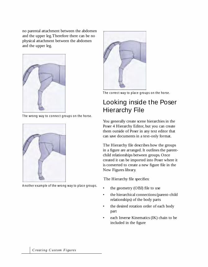
no parental attachment between the abdomen and the upper leg. Therefore there can be no physical attachment between the abdomen and the upper leg.
Looking inside the Poser Hierarchy File
You generally create scene hierarchies in the Poser 4 Hierarchy Editor, but you can create them outside of Poser in any text editor that can save documents in a text-only format.
The Hierarchy file describes how the groups in a figure are arranged. It outlines the parent-child relationships between groups. Once created it can be imported into Poser where it is converted to create a new figure file in the New Figures library.
The Hierarchy file specifies:
• the geometry (OBJ) file to use
• the hierarchical connections (parent-child relationships) of the body parts
• the desired rotation order of each body part
• each Inverse Kinematics (IK) chain to be included in the figure
The wrong way to connect groups on the horse.
Another example of the wrong way to place groups.
The correct way to place groups on the horse.
C r e a t i n g C u s t o m F i g u r e s

Following is an example Hierarchy file; it represents the full Hierarchy for a horse, including curve channels for the tails.
objFile:Runtime:Geometries:horseHi: horseHiP3.obj
1 hip zxy 2 abdomen zyx
3 chest zyx4 lShldr yzx
5 lUpArm yzx6 lForeArm yzx
7 lWrist yzx8 lHand yxz
4 rShldr yzx5 rUpArm yzx
6 rForeArm yzx7 rWrist yzx
8 rHand yxz4 lowNeck zyx
5 upNeck zyx6 head yzx
2 lThigh yzx3 lLeg yzx
4 lShin yzx5 lAnkle yzx
6 lFoot yxz2 rThigh yzx
3 rLeg yzx4 rShin yzx
5 rAnkle yzx6 rFoot yxz
2 tail1 zyx curve3 tail2 zyx curve
4 tail3 zyx curve5 tail4 zyx curve
ikChain LeftLeg lThigh lLeg lShin lAnkle
ikChain RightLeg rThigh rLeg rShin rAnkle
ikChain LeftHand lShldr lUpArm lForeArm lWrist lHand (continued)
ikChain RightHand rShldr rUpArm rForeArmrWrist rHand
The File Header
The first line of the Hierarchy file contains the “OBJ File” command which specifies the location of the OBJ file associated with the new figure.
objFile: Runtime:Geometries:horseHi:horseTex.obj
The file location should be defined using a Macintosh format file specification (that is, using colons). The file location is specified relative to the Poser application folder.
When the Hierarchy file is converted, the text of the OBJ file is read into Poser where a geometry resource is created and linked to the OBJ file. This process results in a new figure file.
From then on, when Poser uses this figure file, the geometry resource is used to define the figure Hierarchy relationships rather than the text stored in the OBJ file. Reading from the geometry resource is dramatically faster.
P o s e r 4

The File Body
The bulk of the Hierarchy file contains lines similar to the one shown below:
The first part of the line indicates Hierarchy level—or the parent-child relationship—of the body part. In this case, the abdomen body part is a child of the body part of the part on the next level up. Hierarchy levels are numbered in descending order, so the next level up from this part is 1.
In the following example, the lShin object is located on the 3rd level of the Hierarchy. The closest level 2 line above would be the lThigh, so the lShin is a child of the lThigh.
The indenting of the lines is not processed but is helpful visually to denote the Hierarchy levels.
The second part of the line specifies the name of the body part. In the example the part is called abdomen. This name must match the group name in the OBJ file.
The 3-character string at the end of the line represents the rotation (or gimbal) order of the body part. A rotation order defined as “zxy” means that a Z axis rotation occurs first, followed by the X, then Y axis rotations.
Poser uses the following X, Y, and Z axis orientations:
A typical Hierarchy file line.
Parent-Child relationships indicated in the Hierarchy file.
Rotation OrderBody Part Name
Hierarchy Level
2 abdomen zyx
2 lThigh yzx3 lShin yzx
4 lAnkle yzx
Parent ObjectChild Object
The body part name in a Hierarchy file line.
The rotation order in a Hierarchy file line.
The X, Y, and Z planes that make up 3D space.
Body Part Name
2 abdomen zyx
Rotation Order
2 abdomen zyx
Y
Z X
C r e a t i n g C u s t o m F i g u r e s

Assigning a rotation order is a three-step process:
• Always place the “twist” axis first. This axis should be placed lengthwise through the object. If the object, like a leg, is built down the Y-axis, specify the Y first, since that is the axis along which the leg twists.
• Of the two remaining rotations, place the one most likely to become 90 degrees last. This helps reduce rotation lock problems that occur when the middle rotation approaches 90 degrees.
• Place the remaining rotation channel second.
Some objects do not align to the major axes. In this case, you can align the coordinate system of the body part later, while adjusting the joint parameters. For the Hierarchy file, pick the closest rotation order. When you align the part later, the twist axis you choose becomes aligned down the length of the body part.
When Body Parts are Stored in Separate Files
If each body part were stored in a separate file, rather than all body parts being groups in a single file, you would specify the full path name for the file at the end of each line. This path is relative to the Poser 4 folder.
Here is an example of three links using this method:
1 link1 yzx :Runtime:Geometries:examples:l1.obj
2 link2 yzx
:Runtime:Geometries:examples:l2.obj 3 link3 yzx
:Runtime:Geometries:examples:l3.obj
Using Curved Transformations
The Curved flag tells Poser that this link should use curve transformations. This is a method of bending designed for the tails of the animal figures in Poser. Here is an example used in the Horse figure:
2 tail1 zyx curve 3 tail2 zyx curve
4 tail3 zyx curve 5 tail4 zyx curve
Inverse Kinematic Chains
The last commands in the Hierarchy file specify the links that compose the individual IK chains. IK can also be defined by using the Poser 4 Hierarchy Editor. Here’s how chains look after they’ve been defined. If you’re creating a Hierarchy file manually, be sure to store IK information in the following format:
ikChain chainName firstLink nextLink nextLink... endGoal
In the example above, the ikChain is defined as follows:
The name of an ikChain cannot contain spaces.
An ikChain line in a Hierarchy file.
Chain Name
ikChain LeftLeg lThigh lShin lAnkle lFoot
P o s e r 4

Converting Hierarchy Files
When you create a Hierarchy file manually, you’ll need to convert it to an actual Poser Hierarchy file. Once the Hierarchy file is completed in the text editor, you can import it into Poser by converting it into a geometry resource (called a CR2 file).
This geometry resource is then used in conjunction with OBJ 3D data to create a new figure file with rotation order and IK relationships as defined by the Hierarchy text file.
On Windows, the resource is a separate file with the suffix RSR. On a Macintosh, the resource is stored with the OBJ file. If you need to edit the resource on a Mac, use a resource editor to remove the text from the OBJ file, or create a new text file by copying and pasting from the old one.
If you make changes to the Hierarchy file and then convert it again, the conversion won’t re-create the geometry resource if it already exists in the OBJ file. So if you are trying to make geometry changes, you must either delete the resource, or start with a new blank text file that contains only the text portion of the OBJ file.
To convert a Hierarchy file:
1 Choose File menu> Convert Hier File. The Open dialog appears.
2 Locate the Hierarchy file you created in the text editor and click Open.
If there are no errors, a Poser Body Library file is created.
The Hierarchy conversion may take several minutes if there is a large geometry file.
The figure file references the geometry file. If the location is of the geometry file changes, you must edit the figure file to designate the new location (specified relative to the Poser application in Mac format).
Verifying Hierarchy Files
Once you begin adjusting the joints, you are not able to regenerate the figure file a second time and have all your joint changes in place. Make sure that all parent-child relationships are correct before editing Joint Parameters. You can make geometry corrections later, but you cannot change the Hierarchy without creating different joints from scratch again.
Adjusting Joint Parameters
When the Hierarchy file was converted into a new figure file, Poser automatically added joints between all the parent and child objects in the figure. These joints may not work as you expect them to because they use the default joint settings.
Before you can pose your figure, you must adjust each body part’s joint parameters. The Joint Parameters palette lets you select each joint, twist, smooth scale, and center parameter and adjust them for optimal bending. Refer to “Adjusting Joint Parameters” on page 312 for details.
C r e a t i n g C u s t o m F i g u r e s

It’s highly recommended that you work from the outside of the figure in, making a first pass through to make sure all origins are located as desired. If you move the origin point (center of rotations) of a body part later, it carries along the other joint changes so the bending characteristics change. You’ll save yourself from doing extra work if you specify the origins (centers) first.
Keep the IK chains turned off until all adjustments are completed. You can use the Zero Figure button to quickly set all rotations to zero while working.
Setting Limits
Limits establish a range of rotation, position, and scale for a given body part. Limits can be set for each body part on the figure. However the most commonly used and logical limits are Bend, Twist, Side-Side, and Front-Back. For these parameters, limits are expressed as the maximum and minimum degrees of rotation.
Limits are set using the Parameter Dial dialog. Refer to “Using the Parameter Dials” on page 121 for how to access the Parameter Dial dialog. Enter the minimum value of the parameter in the Min. Limit field and click OK.
Setting Favored IK Angles
The IK in Poser works from the current rotations of a body part, so proper IK angles must be preset in the figure for it to work predictably. Therefore, the original rotation values loaded on the joint are important to help the IK system know which way to bend some joints.
Before you memorize the default position of all the body parts, you should bend the ones that are used in IK chains so that they favor their natural bending directions. For example, a human thigh is bends slightly forward and out. The shin is bends slightly back and in.
NoteIt’s a good idea to periodically
save your figure to a new
Figure preset as you work so
you can back up if you make
mistakes.
NoteRemember to save your figure
as a new figure in the Figures
library periodically as you
work, so you can back up if you
make mistakes.
Favored IK positions.
P o s e r 4

Do this while keeping all the IK chains turned off. Only turn them on after you have set the favored angles.
Memorizing Default Positions
Memorizing the settings on a figure sets the default values and positions for all the figure’s joints and body parts. The next time you use this figure, the memorized setting are used.
To memorize the figure’s settings:
• Choose Edit menu> Memorize> Figure.
Setting Surface Materials
In order to set the preset material for your figure, you must edit its CR2 file that you created when you converted the Hierarchy file.
The preset material cannot be set from the Poser interface. You’ll need to edit the final Figure library file with a text editor that is capable of opening any kind of file. At the end of the figure file is a block of text that specifies the preset material colors and texture map. If you’ve edited the regular material to be what you’d like, you can copy the information to the preset material.
The following is a sample of the surface material section of the CR2 file:
material shirt
KdColor 0.972549 0.988205 0.972549 1 KaColor 0 0 0 1 KsColor 0.00784314 0.00784314
0.00784314 1 TextureColor 1 1 1 1 NsExponent 30 bumpStrength 0 ksIgnoreTexture 0 textureMap "Biz Man Texture.pict”
0 0
Adding Morph Targets
If you have created Wavefront format OBJ files that have the identical vertex ordering as any individual body part, you can load them as morph targets.
Refer to “Setting up Morph Targets” on page 272 for more information.
Naming Body Parts
The names of the groups you set up in the OBJ file and Hierarchy file may not be the most descriptive names you can use. Once the main parameters are set for the figure, you can change the name of each body part.
To change the name of a body part:
1 Double-click a body part. The Element Properties dialog appears.
2 Enter a new name in the Name field.
C r e a t i n g C u s t o m F i g u r e s
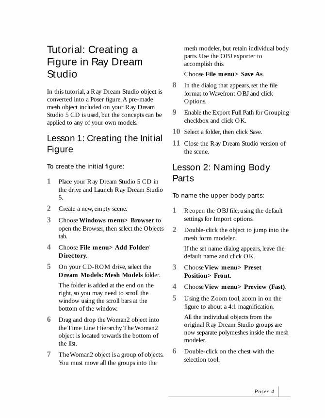
Tutorial: Creating a Figure in Ray Dream Studio
In this tutorial, a Ray Dream Studio object is converted into a Poser figure. A pre-made mesh object included on your Ray Dream Studio 5 CD is used, but the concepts can be applied to any of your own models.
Lesson 1: Creating the Initial Figure
To create the initial figure:
1 Place your Ray Dream Studio 5 CD in the drive and Launch Ray Dream Studio 5.
2 Create a new, empty scene.
3 Choose Windows menu> Browser to open the Browser, then select the Objects tab.
4 Choose File menu> Add Folder/Directory.
5 On your CD-ROM drive, select the Dream Models: Mesh Models folder.
The folder is added at the end on the right, so you may need to scroll the window using the scroll bars at the bottom of the window.
6 Drag and drop the Woman2 object into the Time Line Hierarchy. The Woman2 object is located towards the bottom of the list.
7 The Woman2 object is a group of objects. You must move all the groups into the
mesh modeler, but retain individual body parts. Use the OBJ exporter to accomplish this.
Choose File menu> Save As.
8 In the dialog that appears, set the file format to Wavefront OBJ and click Options.
9 Enable the Export Full Path for Grouping checkbox and click OK.
10 Select a folder, then click Save.
11 Close the Ray Dream Studio version of the scene.
Lesson 2: Naming Body Parts
To name the upper body parts:
1 Reopen the OBJ file, using the default settings for Import options.
2 Double-click the object to jump into the mesh form modeler.
If the set name dialog appears, leave the default name and click OK.
3 Choose View menu> Preset Position> Front.
4 Choose View menu> Preview (Fast).
5 Using the Zoom tool, zoom in on the figure to about a 4:1 magnification.
All the individual objects from the original Ray Dream Studio groups are now separate polymeshes inside the mesh modeler.
6 Double-click on the chest with the selection tool.
P o s e r 4

7 With the chest selected, choose Polymesh menu> Name Polymesh.
8 Change the name to “chest”, then click OK.
9 Repeat the above for the neck portion of the figure, naming it “neck.”
10 Call the left and right shoulder “lShldr” and “rShldr.”
To match Poser conventions, left and right should be from the reference of the figure, opposite to your own left and right. Also, make sure the selection tool has selected the entire polymesh before trying to use name polymesh. If double-clicking doesn’t select the entire polymesh, double-click in an deselected area of the object. If the name polymesh feature is grayed out, then the entire polymesh is not selected.
11 Using the same procedure, name:
• the left and right upper arms: “lUpperarm” and “rUpperarm”
• the left and right forearm: “lForearm” and “rForearm”
• the left and right hand “lHand” and “rHand”
To name parts of the head:
1 Double-click the forehead of the figure to select the head.
2 Use Name polymesh to name the object “head.”
3 Select View menu> Hide Selection.
You may need to zoom in to see the eyes and mouth now left behind.
4 The eyes and mouth are currently a single object. Use the marquee tool to select the figure’s left eye.
5 Choose Selection menu> Detach Polygons to make the eye a separate polymesh.
6 Choose Selection menu> Weld to link the eye to the eyelashes.
7 Choose Name Polymesh to name the object “lEye.”
8 Make the figure’s right eye a separate polymesh, link the eye to the eyelashes, and name it “rEye.”
9 Double-click on the mouth.
10 Use Name Polymesh to name the object mouth.
To name the midsection body parts:
1 Zoom out, and then zoom in around the midsection of the figure.
2 Double-click just above the belt and name this section “abdomen.”
3 Choose View menu> Hide Selection.
4 Use the marquee selection tool to drag a selection around the belt and into the hip.
5 Hold down the shift key and double-click with the selection tool on a deselected area of the hip.
6 Choose Selection menu> Weld to create a single hip object.
7 Make sure you have a polymesh selected, and then name it “hip.”
8 Zoom out, then zoom back in on the legs.
C r e a t i n g C u s t o m F i g u r e s

9 Double-click on a vertex in the shorts below the hip.
You can see that both the left and right side of the shorts are a single object.
10 Use the marquee selection tool while holding down the Alt-Option/Alt key to deselect the figure’s left side of the shorts.
You’ll probably want to start from the outside and slowly deselect inwards until you reach the space between the two legs.
11 Choose Selection menu> Detach Polygons.
12 The bottom hem of the shorts is also a separate object. Select the hem, then deselect the figure’s left side with the Ctrl/Alt-marquee selection.
13 Choose Selection Menu> Detach Polygons.
14 Select just the figure’s right hem.
15 Choose View menu> Hide Selection.
16 Select the polygons that are behind the hem, which connect the shorts to the right thigh.
17 Choose View menu> Reveal Hidden Vertices.
18 Use the selection tool with the shift key to also select the right hem and right leg of the shorts.
19 Choose Selection menu> Weld.
20 Repeat the previous two steps for the left pant objects.
21 Name each side “lPant” and “rPant” respectively.
To name body parts from the thighs downward:
1 Zoom out, and then zoom in from the thighs down.
2 Select the left and right thigh and name them “lThigh” and “rThigh” respectively.
3 Select the left and right calf and name them “lCalf ” and “rCalf ” respectively.
4 The feet are actually broken up into areas of “foot” and areas of “sandal.” For this tutorial, combine the areas into a single left and right foot. Double-click the figure’s right ankle.
5 Use the marquee tool with the Shift key to select the rest of the right foot.
6 Choose Selection menu> Detach Polygons.
7 Choose Selection menu> Weld.
8 Name the object “rFoot.”
9 Repeat for the left foot, naming the resulting object “lFoot.”
To name parts in the shoulder area:
1 Zoom out, and then zoom back in around the right shoulder.
2 Select the right shoulder.
3 Hold down the Shift key and double-click on the very edge of the hem of the shirt with the selection tool. This selects the polygons moving inward towards the upper arm.
4 Choose Selection menu> Weld.
5 Rename the resulting object rShldr.
P o s e r 4

6 Repeat for the left shoulder.
7 Select View menu> Reveal hidden vertices if any are still hidden.
8 Click Done.
9 Save a copy in Ray Dream Studio format.
Lesson 3: Checking Geometry Imports
There are still a couple of steps to complete the object in Ray Dream Studio. Importing this object as a prop into Poser allows you to check the import of the geometry for errors.
This part of the tutorial illustrates potential problems you may have in your models, and how you might fix them.
To check for geometry errors in Poser:
1 Select Save As and set the file type to Wavefront.
2 Locate your Poser folder on your hard drive, then open the Runtime: Geometries folder.
3 Make a new folder called rdswoman.
4 Open the rdswoman folder and save the file as woman.obj.
5 Open Poser.
You may need to close Ray Dream Studio first in order to have enough memory.
6 Click and drag on the Translate In/Out tool to move the figure away from the camera.
7 Select File menu> Import: Wavefront OBJ.
8 Open the woman.obj file. Use the default import options.
9 Use the Translate tool to drag the figure up.
Lesson 4: Fixing Surface Normals
You may notice that some areas seem to have holes or appear inverted. This is because the surface normals are flipped. You should see holes in the eyes, neck, abdomen, thighs, and calves. You can fix this in Ray Dream Studio.
To fix the surface normals:
1 Close Poser, then restart Ray Dream Studio (if necessary).
2 Reopen the woman.obj file.
3 Double-click the object to enter the modeler.
4 Use the selection tool with the Shift key to select the eyes, neck, abdomen, thighs, and calves.
You’ll probably need to select and hide the head to get to the eyes.
5 Choose Polymesh menu> Reverse Polymesh Normals.
6 Choose View menu> Reveal Hidden Vertices.
7 Click Done.
8 Select File menu> Save As.
9 Set the file type to Wavefront.
C r e a t i n g C u s t o m F i g u r e s

10 Click Options.
11 Turn on the Export Texture Maps option.
Although there are no maps assigned in Ray Dream Studio, the Export Texture Maps option allows you to set a material color for each body part in Poser. With this option turned off, the entire figure is considered one surface.
12 Save the file as womanfinal.obj into the rdswoman folder.
13 Close Ray Dream Studio. You do not need it for the remainder of this tutorial.
Lesson 5: Creating the Hierarchy File Manually
In Poser 4, you can create parent-child relationships in the Hierarchy Editor. If you’d rather create them manually, here’s how to do that. Refer to “Using the Hierarchy Editor” on page 290 for how to use the new Hierarchy Editor.
To create the Hierarchy file manually:
1 Using a text editor, create your Hierarchy file to appear as follows:
objFile:Runtime:Geometries:RDSWoman:womanfinal.obj
1 hip zxy2 abdomen yxz
3 chest zyx4 neck yxz
5 head yxz6 lEye yxz
6 rEye yxz6 mouth
yxz
4 lShldr xzy5 lUpperarm xyz
6 lForearm xyz7 lHand xyz
4 rShldr xzy5 rUpperarm xyz
6 rForearm xyz7 rHand xyz
2 lPant yxz3 lThigh yxz
4 lCalf yxz5 lFoot zxy
2 rPant yxz3 rThigh yxz
4 rCalf yxz5 rFoot yzx
ikChain lArm lShldr lUpperarm lForearm lHand
ikChain rArm rShldr rUpperarm rForearm rHand
ikChain lLeg lPant lThigh lCalf lFoot
ikChain rLeg rPant rThigh rCalf rFoot
2 Save the Hierarchy file into the rdswoman folder and name it womanfinal.phi.
To scale the new figure:
1 Open Poser
2 Select File menu> Convert Hierarchy File.
A new figure is created in a group called New Figures.
3 Open the library window and click on the figure tab.
4 Select the New Figures category.
P o s e r 4

5 Double-click the new figure (with the shrugging Poser figure icon).
6 The figure is initially very large. Select “body” from the Current Elements pop-up menu.
7 Double-click the scale parameter dial and change the value to 4.2%.
To adjust body part color:
1 Choose Figure menu> Drop to Floor.
2 Each body part is a different color. Use the color tool on the body parts to better organize the figure.
3 Use a similar color for the chest, abdomen, left shoulder and right shoulder to form the shirt.
4 Use a similar color for the hip, left pant, and right pant to form the shorts.
5 Use a similar color for each foot.
6 Color the mouth red and each eye white.
7 Use a skin tone for the remaining body parts.
8 Select Edit menu> Memorize: Figure.
9 Add the figure to the library, naming it Womanfinal.
Lesson 6: Setting Joint Parameters
If you use the Poser 4 Hierarchy Editor, you can have Poser set joint parameters based on the Hierarchy you define. Even so, you will may want to make adjustments to joint parameters.
Your first task is to set the center of rotation for all body parts. If you change this later, it affects all other bending parameters for parent and child body parts.
To set the hip center of rotation:
1 Switch to outline display mode.
2 Open the Joint Parameters window.
3 Click on Zero Figure.
4 Start by selecting the hip.
5 Change the Center point x and z values to 0.0.
6 Set the y value to 0.9.
7 Set the End Point y value to 0.8. The x and z value should be 0.0.
NoteBefore adjusting joint
parameters, always check that
IK Chains for the figure are
turned off.
C r e a t i n g C u s t o m F i g u r e s
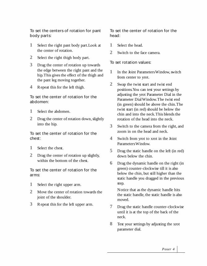
To set the centers of rotation for pant body parts:
1 Select the right pant body part.Look at the center of rotation.
2 Select the right thigh body part.
3 Drag the center of rotation up towards the edge between the right pant and the hip. This gives the effect of the thigh and the pant leg moving together.
4 Repeat this for the left thigh.
To set the center of rotation for the abdomen:
1 Select the abdomen.
2 Drag the center of rotation down, slightly into the hip.
To set the center of rotation for the chest:
1 Select the chest.
2 Drag the center of rotation up slightly, within the bottom of the chest.
To set the center of rotation for the arms:
1 Select the right upper arm.
2 Move the center of rotation towards the joint of the shoulder.
3 Repeat this for the left upper arm.
To set the center of rotation for the head:
1 Select the head.
2 Switch to the face camera.
To set rotation values:
1 In the Joint Parameters Window, switch from center to yrot.
2 Swap the twist start and twist end positions. You can test your settings by adjusting the yrot Parameter Dial in the Parameter Dial Window. The twist end (in green) should be above the chin. The twist start (in red) should be below the chin and into the neck. This blends the rotation of the head into the neck.
3 Switch to the camera from the right, and zoom in on the head and neck.
4 Switch from yrot to xrot in the Joint Parameters Window.
5 Drag the static handle on the left (in red) down below the chin.
6 Drag the dynamic handle on the right (in green) counter-clockwise till it is also below the chin, but still higher than the static handle you dragged in the previous step.
Notice that as the dynamic handle hits the static handle, the static handle is also moved.
7 Drag the static handle counter-clockwise until it is at the top of the back of the neck.
8 Test your settings by adjusting the xrot parameter dial.
P o s e r 4

To adjust scale values:
1 Switch from xrot to neck_scaleY. This controls the blending zone for the y-axis scaling of the neck when scaling the head.
2 Set Low start to 5.97 and Low end to 6.14.
This sets the blending to within the neck, below the chin.
3 Select the mouth_scaleY.
4 Set Low start to 6.4 and Low end to 6.27.
5 Select lEye_scaleY.
6 Drag the High end up towards 9.
7 Repeat this for the right eye.
8 You can now scale the head to see the effects.
You can now set limits for each body part.
To set remaining limits.
1 Repeat the above procedures for the remaining body parts, so that your figure moves and bends realistically.
2 Set the default IK angles. Memorize the default position.
3 Save the figure to the library.
C r e a t i n g C u s t o m F i g u r e s

16Using Poser 4 with Other Applications
Using Poser with Ray Dream Studio 5Poser adds features to Ray Dream Studio’s Mesh Form Modeler. The Mesh Form Modeler lets you edit an object’s surface directly, by editing the points that define its surface. For a full description of the Mesh Form Modeler, refer to the Mesh Form Modeling chapter in your Ray Dream Studio manual.
The following Mesh Form Modeling features have been added to the Selection and Polymesh menus.

Selection Menu
Name PolygonsName EdgesName Vertices:
Apply group names to selected polygons or edges. Poser uses these group names to name body parts when importing Hierarchy files to create new figures. Refer to “Creating Custom Figures” on page 301 for more information.
Detach Polygons: Separate the current selection into a new polymesh. The edges and vertices in common with the original and the new polymesh are duplicated, so that no polygons are lost. This is useful for breaking up a solid object into individual sections for use as body parts in Poser.
Polymesh Menu
Name Polymesh: Similar to name polygons, this option works on an entire Polymesh. It creates a group name for the polymesh; Poser uses this name when importing Hierarchy files to name body parts. Refer to “Creating Custom Figures” on page 301 for more information.
Reverse/Standard Polymesh Normals: When you export geometry in an OBJ file, Ray Dream assigns each polygon a direction, called a surface normal.
For some objects, Ray Dream Studio may assign normals in the wrong direction. In this case, it appears that you are seeing the interior of the object from the front instead of the front faces. Select these parts of the model in the Mesh Modeler, and then select Polymesh menu> Reverse Polymesh Normals. The OBJ exporter flips the normals when exporting.
The Selection menu.
The Selection menu.
U s i n g P o s e r 4 w i t h O t h e r A p p l i c a t i o n s

Importing and Exporting OBJ Files
The OBJ file format can be used between Ray Dream Studio and Poser to:
• Create new figures from scratch using Hierarchy files
• Edit Poser geometry to create new morph targets
• Create objects in Ray Dream Studio to use as props in Poser
Importing OBJ Files
When importing OBJ files, the available options are:
Group Information: Although Wavefront objects can have a First or Last name associated with each group, Ray Dream Studio requires a single name per group. The Group Information option lets you choose the name to use within Ray Dream Studio. To import an object as a single polymesh, you must select the Make Only One Group radio button.
Scaling Factor: Define the unit conversion between Ray Dream Studio units and OBJ units. If you are importing Poser geometry to create morph targets, always use the default of 4.00 inches.
Create Meshform Objects: If None is selected, the object imports as an external object, with the minimum modeler as its default modeler. If One is selected, the object imports as one meshform object. The object is still broken up by its group names as individual polymeshes within the modeler if
you did not use Make Only One Group from Group Information. If One for Each Group is selected, an individual object is created for each group.
Transpose Coordinates: Compensate for the difference in world coordinates between other programs and Ray Dream Studio. Ray Dream Studio has the y and z coordinate axes transposed from other programs, including Poser.
To import an OBJ file:
1 Select File menu> Import or File menu> Open to open an OBJ file.
2 Set the file type to Wavefront (*.obj).
3 Select the OBJ file and click Open.
Exporting OBJ Files
When exporting OBJ files, you are presented with the following options.
Export Normals: Toggles exporting of surface normals on and off. You almost always want this setting turned on.
Export UV values: Toggles exporting of UV texture data on and off. Turn this on to enable texturing in Poser. Poser only supports UV mapping of figures and props.
Export Full Path For Grouping: If you are saving a number of Ray Dream Studio objects that have been grouped, the groups are saved as Wavefront groups.
NoteUse the default settings when
importing Poser figures.
P o s e r 4

Export Texture Maps: Creates a Wavefront Material file to be used with the OBJ geometry file. This file describes how objects are textured. It creates one material for each group.
Transpose Coordinates: Compensates for the difference in world coordinates between other programs and Ray Dream Studio. Ray Dream Studio has the y and z coordinate axes transposed from other programs, including Poser.
Degree of Tessellation: Controls the smoothness of the exported object.
Textures Format: If the Export Texture Maps option is turned on and the objects have attributes which must be converted to texture maps, this controls the format of the texture files and their resolution.
To export an OBJ file:
1 Select File menu> Export or File menu> Save As.
2 Set the file type to Wavefront (*.obj).
3 Click on the Options button to alter the export options.
Using Poser with Painter 3DYou can export a figure as an OBJ file from Poser and then paint on it as you would any other model.
To use a Poser model in Painter 3D:
1 Create and pose a figure in Poser.
2 Choose File menu> Export> Wavefront OBJ.
3 In the dialog that appears, select the Single frame option.
Poser figure.
Select Single Frame.
U s i n g P o s e r 4 w i t h O t h e r A p p l i c a t i o n s

4 In the Hierarchy Options dialog that appears, click OK to use the default settings.
5 Launch Painter 3D.
6 Choose File menu> Acquire > wavefront obj.
The figure appears in the model window.
7 Create a texture map for the body and hair.
8 Save the texture maps as pict files for use with your Poser model in other applications.
Poser figure in the Painter 3D model window.
Painter 3D texture map.
Painter 3D hair texture map.
Painter 3D texture map applied to figure.
P o s e r 4

Using Poser with Bryce 3DYou can import Poser Figures as OBJ into any Bryce scene.
To use a Poser model in Bryce:
1 Create and pose a figure in Poser.
2 Choose File menu> Export> Wavefront OBJ.
3 Select the Single frame option.
4 In the Hierarchy Options dialog that appears, click OK to use the default settings.
5 Launch Bryce.
6 Open or create a scene where the Poser figure is to be placed.
7 Choose File menu> Import Object to add the figure to the scene.
Poser figure.
Select Single Frame.
The unrendered scene.
The rendered scene.
U s i n g P o s e r 4 w i t h O t h e r A p p l i c a t i o n s

8 Scale and position the figure appropriately.
The figure is placed in the scene with a default gray texture attached.
9 If the figure has hair, the hair and body import into Bryce as a group. To map each part:
• Ungroup the hair and body by clicking the ungroup button, which appears beside the object when selected.
• Select the body to map it first.
To apply a texture map to the figure:
1 Click to select the figure.
• Click the Edit Materials icon in the Edit Palette.
The Materials Lab appears.
2 Click column A for Diffuse and Ambient channels.
Scale and position the figure.
The default gray texture.
The Materials Lab.
Select Diffuse and Ambient channels.
P o s e r 4

3 Click the Image Texture button in material A.
4 Set the mapping mode to parametric and click the Texture Source Editor button in material A.
The Texture Source Editor appears.
5 Click Load (above the first large pict box).
6 Apply texture map(s) with one of the following methods.
• Select and open the pict file texture you created in Painter 3D. Refer to “Using Poser with Painter 3D” on page 326 for details on creating a Painter 3D texture file for a Poser model.
• To use the default texture from Poser, open Poser:Runtime:Textures and select the appropriate texture. Poser renders as a multiplication of the texture and body part color.
• Open the Poser pict file in an image editing application (such as Painter or Photoshop), edit the colors, add patterns, then save the file as a new pict file for use with your figure.
• Use Bryce’s textures to create surreal figures (such as rock or glass).
The Image Texture button.
The Texture Source Editor button.
The Texture Source Editor. Open the Painter 3D texture file.
U s i n g P o s e r 4 w i t h O t h e r A p p l i c a t i o n s

7 Click on the black dot above the second large pict box to delete the mask.
8 Click on the check mark to accept the deletion.
9 Adjust other material channels appropriately.
For this scene, the specularity and reflection were increased to make the swimmer look wet.
10 Click on the check mark to accept material.
11 With the hair selected, repeat these steps to apply the hair texture.
Using Poser on the World Wide WebIf your computer is connected to the Internet, you can access the World Wide Web directly from Poser. You can exchange information with other Poser users, visit the MetaCreations site, or view the latest technical support information.
Internet Connection
You must have an Internet connection and a browser package to use the Web-based features of Poser. If you have an account with an ISP (Internet service provider), such as EarthLink, AOL, or other provider, you are ready to go. Otherwise, acquire an Internet account and install a modem on your computer. Once you have a connection, you can start using Poser’s Internet-based features.
If you have an e-mail only account with a provider such as Juno, you will not be able to use all of the Web-based features of Poser.
Using a Browser
The two most common browsers are Internet Explorer and Netscape Navigator.Use version 4.0 or greater of either browser to take advantage of interactive HTML features.
The final result.
P o s e r 4

Windows Users
If your computer is running Windows 95, Windows 98, or Windows NT 4.0 or greater, you should already have Internet Explorer installed. If not, you’ll need to install it. Once you have an account with an ISP, you can start using the Web-based features of Poser.
Macintosh Users
Once you have an account with an Internet provider and a browser software package installed, you can start using the Internet-based features of Poser.
Accessing the Web
Poser now has a “Links” menu that will launch your default browser and take you to the one of the Poser-related Web links in your links list. You can update this links list to add your own links and delete any default links you do not use.
In addition, you can also export both still files to the Web using the Export Image or Render to Disk options on the File menu. You can export animations through the Render Animation feature.
To select a Web link:
1 Choose Help menu> MetaCreations Web Links> choose a link for links to MetaCreations Web pages
or
Help menu> Other Web Links> choose a link for links to Poser Web sites.
2 Poser launches your browser and opens the desired link.
Modifying Poser Web Links
You can create, delete, or edit Poser Web Link files. Each link is a simple ASCII file that contains a line with the link’s URL.
To add, delete, or edit Web links:
1 From your desktop, open: Poser:Runtime:Weblinks:MetaCreations/Other Web Links. Link files appear in these folders.
2 Do any of the following:
• To change the name of a link, highlight the filename and enter a new name.
• To delete a link, drag its file to the Trash/Recycle Bin.
• To create a new link, open a text editor such as Note Pad or SimpleText. Enter the URL on the first line of the file, and save the file in the Poser:Runtime:Weblinks:MetaCreations/Other Web Links directory.
• To change a link, open the link file in your text editor, enter the new URL, then save and close the file.
3 Restart Poser.
Your menu reflects the new links.
U s i n g P o s e r 4 w i t h O t h e r A p p l i c a t i o n s

Using Poser with MetaStreamYou can export Poser scenes to MetaStream format files for use on web sites.
To export a Poser scene to MetaStream format:
1 Create and pose figures and objects in Poser.
2 Choose File menu> Export> MetaStream.
Two file formats are generated:
• HTML: embeds MetaStream output generated by Poser using the EMBED tag.
• MTS: contains compressed geometry and textures.
Double-click the HTML file to open the output.
Use MetaStream objects as embedded objects in an HTML page. This gives the page author full control over a wide range of rendering and interaction options described at the MetaStream Web site:
http://www.metastream.com
If you open a raw MTS file, the plug-in runs with all attributes set to default values.
Textures generated by Poser are already lit (by real light) and do not need additionally shading by synthetic lights, so set texture shading to off.
Using Poser with CanomaCanoma models can be exported in the OBJ format for import into Poser.
Exports to Poser Prop command within Canoma exports a .pp2 file and several .bmp (Win)/.pict (Mac) textures.
To use a Canoma model in Poser:
1 Manually copy or move the .pp2 file to any immediate subfolder of Runtime:Libraries:Props.
2 Move or copy all the .bmp or .pict files to:
PoserAppDirectory:Runtime:Textures
NoteIf Infini-D is installed on your
computer, MTS files appear with
an Infini-D icon. Double-clicking
this icon launches Infini-D. If an
error message appears, make
sure the Infini-D path information
in the HTML file is correct and
that all required libraries are
available.
P o s e r 4

The Canoma-generated object or scene appears in the list of props (without a special icon) and with the name you give the prop. You can place and work with the prop like any other.
A word of caution: do not give two Poser generated props the same name or you will overwrite part of one prop’s textures.
TipKeep shortcuts and aliases for the
Poser texture and prop type
folders handy to where you
generate the prop file, then drag
the files onto the shortcuts. This is
faster than hunting down the
directory.
U s i n g P o s e r 4 w i t h O t h e r A p p l i c a t i o n s


ATroubleshooting
Installing Poser
If you have trouble with your installation, be sure to read “Installing Poser” on page 15.
Poser (Windows) locks up the first time you launch it
Many video cards cannot use hardware acceleration at the high setting in any screen depth other than High Color or 16-bit. There are two ways to correct this problem:
To set your display to High Color or 16-bit:
1 Right-click on your desktop.
2 Select Properties.
3 Choose the Settings tab.

4 Change the color palette to High Color (16-bit.).
To lower the graphics hardware acceleration setting in Windows:
1 Select the Window Start button.
2 Choose Settings.
3 Open the Control Panel.
4 Double-click the System Icon.
5 Select the Performance tab.
6 Click Graphics.
7 Adjust the Hardware Acceleration slider to a lower position.
8 Test your system using this method until you find the level of hardware acceleration compatible with Poser.
Poser (Windows) does not accept your serial number
This problem may be related to your video drivers. You can set your display to VGA (256 color). Or on NT, reboot and choose NT VGA mode.
To allow for CD-ROM support and 16-color video:
1 Right-click on your desktop.
2 Select Properties.
3 Choose the Settings tab.
4 Change the color palette to VGA (256 color).
If this procedure does not work, enter the serial number in all fields (name, serial number, etc.).
Poser (Macintosh) does not accept your serial number
Create a custom extension set according to the instructions in “Macintosh Installation” on page 15.
Macintosh Extension conflicts
Create a custom extension set as described in “Macintosh Installation” on page 15, add extensions, and test Poser to see if the conflict is resolved. Some culprits of extension conflicts are scheduling applications, task bars, and RAM doubling type applications.
Interface corruptions are caused by bad fonts (such as system 8-8.1’s charcoal). Update older versions of Adobe Type Manager (ATM), as they can have conflicts.
Tr o u b l e s h o o t i n g

BGlossary
Aliasing A visual artifact caused by low-resolution sampling that can cause hard edges or areas of high frequency in an image to look jagged. Refer also to Anti-aliasing.
Angle Falloff The amount of diminution in the brightness of a spotlight toward the edge of a light cone.
Animation Controls A control panel located at the bottom of the Poser Workspace that lets you quickly set up and preview animations using a simple click and drag interface.
Animation Duration The amount of time that an animation lasts.
Animation Elements List A list that displays all figures, lights, cameras, and props currently in the studio. The Animation Elements List is accessed on the Animation palette and is used during the editing of animation keyframes.

Animation Frame Count Refer to Frame Count.
Animation Frame Rate Refer to Frame Rate.
Animation Frame Size Refer to Frame Size.
Animation Graph Palette Refer to Graph Palette.
Animation Palette A comprehensive dialog which lets you edit keyframe positions, create complex animations, animate individual body parts, and edit keyframes within an animation. Refer also to Animation Elements List.
Anti-aliasing The process of eliminating aliasing by higher resolution sampling, so that hard but jagged edges appear smooth and clean.
Auxiliary Camera An additional camera view. Like the Main camera, the auxiliary camera rotates around the center of the studio.
AVI A PC file type used for saving movies.
Axis A hypothetical linear path. The X, Y, and Z axes (width, height, and depth, respectively) define the directions of the 3D universe. The axis along which an object is rotated is the axis of rotation. An object’s axes are parallel to its bounding box.
Box Tracking A tracking style that displays figures and objects as boxes at all times. Refer also to Figure Tracking, Fast Tracking, and Full Tracking.
BMP A Windows file format for bitmapped or pixel-based images.
Break Spline Interpolation A type of animation interpolation which has no intermediate poses. Position changes abruptly only at the keyframes. Refer also to Constant Interpolation, Linear Interpolation, and Spline Interpolation.
Bump Map A type of surface material that determines the shape of bumps or dents on an object’s surface.
Camera Plane The plane that a camera moves along.
Child An object that is linked to another object (its parent) in a hierarchy. When the parent is moved, the child moves with it. Refer also to Parent.
Chain Break A tool that breaks the chain of parts affected in a translation.
Constant Interpolation A type of animation interpolation that maintains a keyframe position, then instantly changes to the next pose. Refer also to Break Spline Interpolation, Spline Interpolation, and Linear Interpolation.
Deformers Properties that can be applied to an object (or group of objects) to deform its geometry. In Poser, deformers include magnets and waves.
Depth Cueing An effect which creates the appearance that elements far away are dimmer than elements closer to the camera.
Display Style A style that determines how figures, elements, or the document are displayed in the Document window.
G l o s s a r y

Distance Falloff The distance from a spotlight itself to the point where the light has no effect.
Distant Light Refer to Infinite Light.
Document Display Style Refer to Display Style.
Dolly A camera view where the camera moves around in 3D space as if gliding on the surface of a sphere surrounding the Poser studio.
DXF Originally developed for use with AutoCad, this is the most common 3D file exchange format.
Fast Tracking A tracking style that displays figures and objects as boxes only when they are moving. Refer also to Box Tracking, Full Tracking, and Figure Tracking.
Figure Ring The ring that surrounds a figure and allows you to select the entire figure (as opposed to its elements).
Figure Tracking A feature used during the posing and shaping phases that changes the display of an object as you reposition its parts. Refer also to Box Tracking, Fast Tracking, and Full Tracking.
Flyaround View A camera view that lets you see all the contents of the studio at once. In this view the camera moves around an imaginary track above and away from the center of the studio.
Focal Length A camera control that changes the camera perspective in the studio. Decreasing the Focal Length increases the sense of perspective. Increasing the Focal Length “flattens” the sense of perspective.
Frame Count The total number of frames in an animation.
Frame Rate The number of frames used during one second of animation.
Frame Size A width or height value for the animation output set during Animation Setup. The aspect ratio of the Document window determines the other value.
Full Tracking A tracking style that uses a display style at all times, resulting in a slower motion as you manipulate poses and shapes. Refer also to Box Tracking, Fast Tracking and Figure Tracking.
Graph Palette A palette that lets you perform precise edits on keyframes and adjust the interpolation methods used in an animation. The palette is made up of two axes and a graph. The horizontal axis displays frame numbers which represent time in your animation.
Grouping Tool An editing tool that allows you to select specific polygons on an object and group them.
Group Edit Palette A dialog that accompanies the Grouping tool. The Group Edit palette includes various options for grouping and creating props.
Hierarchy A tree structure that lists the objects in the scene and shows their logical relationships to other objects.
P o s e r 4

Horizon Line A reference line in a studio that shows perspective.
Implicit (UV) Mapping Refer to UV Mapping.
Infinite Lighting A lighting control that shines light into the studio the same way the sun or moon shines on the Earth. The light rays from a distant source are parallel as they enter the Poser studio.
Interpolation An animation process by which Poser fills in the gaps between keyframes to create the illusion of motion. Refer also to Break Spline Interpolation, Spline Interpolation, Linear Interpolation, and Constant Interpolation.
Inverse Kinematics (IK) A feature which determines the dependency of jointed structures in movement. When an extremity on a figure moves, IK determines how objects joined to it respond.
Keyframe A representation of one point in time in an animation. Keyframes store changes in position for each body part in the figure, as well as changes in scale, color, lighting, or camera position.
Keyframe Animation The process of assigning different poses to different keyframes during an animation.
Keyframe Interpolation The method Poser uses to calculate the “in between” position of objects or elements. Refer to Spline Interpolation, Linear Interpolation, Break Spline Interpolation, and Constant Interpolation.
Libraries Palette A Poser library dialog by which figures, poses, props, lights, cameras, and animations are saved and retrieved.
Light Control A control used to create and position lights in the Poser Workspace. The Light control is located by default in the top left corner of the Poser Workspace.
Light Indicator A visible representation of a light source. The infinite light indicator appears as a ring around the figure. The Spotlight indicator appears as the outline of a Spotlight.
Linear Interpolation A type of animation interpolation that places intermediate poses at equal increments so the motion is smooth and straight. Refer also to Break Spline Interpolation, Spline Interpolation, and Constant Interpolation.
Magnet A deformer that distorts an object as if it were being affected by a magnet.
Memorize A feature that sets a default value for a Parameter Dial.
Memory Dots A graphical control that allows you to save multiple poses, cameras, and UI configurations within a file.
Morph A change made to the form or character of an object.
Morph Targets A parameter added to an object that allows you to gradually reshape it.
Natural Light Refer to Infinite light
OBJ A file format used in many 3D graphics programs.
G l o s s a r y

Orthogonal A camera projection of a scene which has no perspective distortion.
Object Any 3D volume or other item that appears in the universe, including cameras and lights. When objects are grouped, their group is also described as an object.
Orbit Refer to X, Y, Z Orbit.
Orientation The direction an object faces as defined by the compound effect of the object’s pitch, yaw, and roll. Usually, the most important aspect of an object’s orientation is its relation to other objects. An object’s relation to the viewpoint can be changed by moving the current camera.
Origin Refer to Prop Origin.
Parameter Dimensions or encompassing characteristics applied to a figure or object to define its relationship to itself or other objects.
Parameter Dial Movement controls that allow figure posing using precise numerical increments. By dragging a dial you can move a body part in small increments, allowing for precise poses.
Parent An object that is linked to another object (its child) in a hierarchy. When the parent is moved, the child moves with it. Refer also to Child.
Phoneme A linguistic term for the position of the lips, teeth, and tongue as they make sounds that produce specific letter sounds. In Poser, you can create the appearance of phonemes to create realistic facial animations, simulating speech.
PICT A standard Macintosh file format for pixel-based images.
Pitch The aspect of an object’s attitude that describes its angular deviation along its vertical (top-to-bottom) axis.
Point of View (also viewpoint) The position and angle from which a scene is viewed. The point of view (POV) is always through a camera. You may add several cameras, positioned and angled differently, and switch the Universe window POV between them. When you render an image, you choose the POV from which the image should be taken.
Properties A collection of characteristics applied to (or available for) an object. Properties for an object appear in its Properties dialog.
Prop Origin 3D cross-hairs that represent a prop’s center of rotation and scale. When you rotate a prop, it moves around the origin point.
QuickTime A standard Apple file format for movies.
Reflection Map A type of surface material that determines what is reflected on an object’s surface.
Render The process of building a 2-dimensional bitmapped image from the information contained in a 3-dimensional scene.
Roll A camera command that tips the Dolly camera to the left or right.
P o s e r 4

Scale A value that describes the space an object occupies; synonymous with Size, though Size implies an absolute space.
Scrubber A control which represents the current period of time on the Animation Timeline. By positioning the Scrubber at different points in time, you can move through time to set up keyframes.
Smart Prop A prop setting that describes a specific location for a prop in relation to another object. The location is found when a smart prop is retrieved from the library.
Spline Interpolation A type of animation interpolation which places intermediate poses (and settings) on a curve. The element or object accelerates and decelerates in and out of the motion. Refer also to Break Spline Interpolation, Constant Interpolation, and Linear Interpolation.
Spotlight A light that is cast in a specific direction along a cone-shaped path, creating a “stage spot” effect.
Spread The amount of space between the fingers, controlled by the Spread Parameter Dial. Higher values spread the fingers out, while lower values push the fingers together.
SMPTE ISO standard acronym to describe time by hours:minutes:seconds:frames.
Surface Materials Rendering controls that let you apply texture characteristics to an object.
Symmetry A menu control that allows pose characteristics to be copied from one side of the body to another.
Taper Adjusts the scale of one end of an element only—the other end does not change.
Texture Map A type of surface material that determines the texture of an object’s surface.
TIFF A graphics file format used for still-image bitmaps.
Timeline A graphical representation of time located in the Animation Controls.
Tracking Refer to Figure Tracking.
Translate In/Out Tool An editing tool that moves a selected part or figure in the z dimension.
Translate/Pull Tool An editing tool that moves a selected part or figure vertically or laterally (in the x and y dimensions).
Translation A manipulation of the position or attitude of an object. Also, an extrusion in which the cross section remains at one angle, regardless of the curvature of the sweep path.
Transparency Map A type of surface material that determines what is reflected in a transparent object’s surface.
Turbulence A Parameter Dial that defines the roughness of a wave pattern. Go from a smooth pattern, to a jagged, turbulent one.
UI The User Interface (UI) is what appears when you launch Poser. The screen is the interface between the user and all of the features of the application. It contains buttons, pull-down menus, and paths to the features themselves.
G l o s s a r y

URL Uniform Resource Locator (URL) is the string of locations in a Web address. The URL for MetaCreations, for example, is:
http://www.metacreations.com
Use Limits A feature that keeps body parts within a natural range of motion. Use Limits does not apply to parts involved in IK (Inverse Kinematics).
UV Mapping A 3D coordinate mapping system. UV coordinates are used in parametric mapping to align points on the shader with points on the object.
Vanishing Lines A guide used to achieve a realistic perspective when matching the view of a figure with the perspective in a background image.
Vector A line of movement defined by its end points or by the current position and one other point.
Vertex A control point on a path. Paths begin, change angles, and end at vertices.
Viewpoint Refer to Point of View
VRML Virtual Reality Modeling Language —a file format that can be imported and exported in Poser.
Walk Designer A dialog that allows you to experiment and control motion creating a realistic walking gait. The designer also provides a real-time preview of the walk.
Wave A deformer that distorts an object as if it were being affected by a wave.
Waveform The graphic representation of a sound file.
Wavefront A file format designating Wavefront OBJ.
xOrbit A camera control that tilts the camera forward or backward.
Yaw The area the Dolly camera points at as it rotates 180 degrees on its y-axis.
yOrbit A camera control that tilts the camera to the left or right.
zOrbit A camera control that orbits the camera around the studio. The camera continues to point at the center of the studio as it orbits.
P o s e r 4

G l o s s a r y

Index
Numerics2D rendering 259
3D programs
props and 167
3D Studio file format
exporting 48importing 47, 166
3DMF file format
exporting 48importing 47, 166
A
Accessing the web 332
Add Element to deform button
magnet object properties 146
wave object properties 151
Add Keyframes button 213, 218
Add Morph Target
body parts 42, 126Prop properties 170
Adding
animations to library 230chain breaks 120figures to studio 33hair 163infinite lights 193keyframes 213, 218, 228lights 193poses to the library 135props 166spotlights 193
Adjusting light indicators 196
Advancing keyframes 220, 221
Aiming
infinite lights 194lights 193, 197spotlights 194
Alias
defined 337rendering 262
Align
head 237joint parameters 282
All Elements option 218
Deleting keyframes 219Next Keyframe 221Previous Keyframe 221
Allocating memory 25
Always Complete Last Step 237
Ambient color 257
Amp Noise dial, waves 150
Amplitude dial, waves 150
Angle Falloff
defined 337spotlights 201
Animals
heads and 133posing 133
Animating checkbox
Light properties 192
Animating On/Off icon 181
Animation
adding keyframes 213, 218adjusting current time 212adjusting scrubber 212align head 237All Elements button 219Always Complete Last Step
237background and 211
break spline interpolation 206, 225
BVH files 242cameras 181, 237, 239changing Timeline
Ruler 217clearing keyframes 219clip sound file 240constant interpolation
206, 224controls 206copying keyframes 222, 223creating 209Current Frame
Indicator 227cycle repeat 237deformers and 208deleting keyframes 213,
219, 220designing walks 234Dolly camera 238duration 210, 337editing 206, 213editing graph 227editing interpolation 225editing keyframes 217editing sound files 240editing walks 235Elements list 215, 216, 337Face camera 238faces 207figures and 205, 206frame count 215, 339frame rate 214frame size 210go to keyframe 221green keyframes 225Hand cameras 238hands 207how it works 206indicator 239

interpolation 206, 224interpolation graph 226Inverse Kinematics and 207key-shaped indicator 239lights 239linear interpolation
206, 224loading walks 236magnet deformers and 208Main camera 238morph targets and 209motion 232moving keyframes 221, 222navigation controls 220Next Keyframe button
220, 221palette 206, 213previewing 206Previous Keyframe
220, 221props and 208red keyframes 225rendering 264saving walks 236selecting elements 216selecting keyframe
range 228selecting keyframes
217, 227setting dimensions 210setting duration 210setting up 210, 214simulating speech 207Sound Display 241sound files 240sound range 240spacing keyframes 231spline interpolation
206, 224syncing sound 240techniques 231This Element button 218,
219, 220timeline 211, 217timing keyframes 223Transition options 237
turn camera off 239walk in place 236walk paths 233walking 233wave deformers and 208waveforms 241window size ratio 210
Animation Controls 209
command 214defined 337scrubber 211understanding 24
Animation Palette 24
Animation palette 213
add keyframes 218adding keyframes 218clearing keyframes 219current time and 215defined 338delete keyframes 219Elements List 215frame numbers 215show graph display button
225This Element button 219Timeline 217
Animation Setup command 210, 214
Animations
adding to library 230advanced features 224cameras and and 187creating 205, 209current time 215current time and 211lights and 203looping 229multi-frame 230playing 228poses and 35, 48, 135, 157previewing 228, 229saving 265speed 210stopping 228
techniques 231
Answering questions 13
Anti-alias
defined 338Document render 263rendering 262
Apply Bulges parameter 284
Apply Bulges parameters 285
Apply standard rotation order299
Applying
preview modes 40standard hierarchy 299symmetry 125, 142walks 236
Arms, selecting 43
Articulated Hand model 128
Aspect ratio, rendering 261
Auto Balance, posing with 134
Auxiliary Camera 179, 338
AVI
background 211defined 338Footage command 211importing 47, 211rendering and 264
Axis, defined 338
B
Background
animation 211image 211movie 211
Background color
Rendering and 262setting 29
Background Picture 262
Backgrounds
clearing 44
I n d e x

color 194, 262pasting figures onto 44rendering and 262Workspace 28
Bend dial 122
Bend option, Element Properties 42, 126
Bending
body parts 122figures 127joint parameters 281, 283props 12
Black, rendering and 262
Blend zones 278
Blink, posing for 131
Blocks, selecting keyframes 222
BMP file format 251
defined 338importing and 47rendering and 264
Bodies
scaling 142sizing 142
Body parts
attaching to prop 172bending 42, 122, 126casting shadows 42, 126front-to-back
movement 123grouping 305hiding 42, 126locking 134morph targets and 42, 126naming 42, 126options 126Parameter Dials and 141pointing 134properties 42replacing with props 173scaling 140, 141selecting 43, 114side-to-side movement 122surface materials and 245
tapering 141turning 123twisting 118, 122
Body shaping 138
Box Tracking 30, 338
Break Spline interpolation 206,225, 338
Breasts, changing size 141
BRLarge 141
Brow parameter 132, 153
Browser 331
BRSmall 141
Bryce 3D, using with Poser 328
Bump maps
converting PICT 248custom 247defined 338loading custom 248painting 248props and 171rendering with 263Strength slider 247templates 248
BumpNose parameter 132, 153
BVH file format 47
Importing BVH files 242
C
Camera Controls
understanding 21using 181viewing figures and 36
Camera parameters
Focal Length 183Pitch 184Roll 184Scale 184xOrbit 184Yaw 184yOrbit 184
zOrbit 184
Camera Plane
controls 181defined 338
Camera Selection control 180
Cameras
animating 181, 237animation indicator 239auxiliary 179category 32controls 21Dolly 179face 179flyaround view 180focal length and 183hand 179Hand Cameras 127how they work 177locking 186main 179memory dots 37, 187options 185Orthogonal 179parameters 183pointing 186Posing 179posing and 110properties 185roll 183rotation trackball 182saving positions 37, 186saving to library 186scaling 183See also Librariesselecting 36, 180shortcut icons 180switching 180turning animation
on/off 239
Canoma, using with Poser 333
Cartoon style 39
Cartoon w/Line style 39
Casting shadows 201
P o s e r 4

Casts Shadow button, properties 42, 126, 170
Center Point
joint parameters 282, 283, 285
Center, joint parameters 280, 282
Chain break
adding 120posing and 120removing 121tool 120, 338
Changing
defaults 46play range 229prop origin 169Timeline Ruler 217views 180
Characters, figures 153
Cheeks parameter 132, 153
Child
defined 338parent and 296See also Parent, Hierarchy
Chin parameter 132, 153
Clear Background Picture 44, 211
Clearing
background 44keyframes 219
Clipping sound files 240
Clothing
conforming to figure 12, 165
figures and 164hiding skin under 166without a figure 166
Collapsing
elements list 216Hierarchy Editor 291
Color controls
Document window and 29
Color dot 199
Color tool 28, 139
Colors
adding 139ambient 257backgrounds 194Document window 29figures and 139, 199highlight 256Light properties 192lighting and 199object 255props 171reflective 254setting 255
Combining props 304
Conforming
clothing to figures 165figures and clothing 12hair to figures 164
Constant interpolation 206, 224,338
Contacting
Technical support 14
Controls for animation 206
Copying 13
blocks of keyframes 223joint parameters 286keyframes 222, 228poses 125
Copying and Pasting 143
Count, changing 215
Create Meshform Objects 325
Create Walk Path command 233
Creating
animations 209figures 301figures from props 304library sub-categories 34motion 232prop parameters 169props 168
walk paths 233
Current Element menu
props and 168selecting and 113
Current Figure menu
animals and 133
Current Frame Indicator 227
Current time
adjusting 212for animations 211moving 215scrubber 211
Custom figures 301
Custom morph targets 154
Customer service 14
Customizing
bump maps 247reflection maps 254texture maps 250transparency maps 252
Cycle repeat 237
D
Darkness of shadows 202
Defaults
changing 46restoring 46
Deformer Tools 143
Deformers 12
animating 208defined 338grouped objects, using
with 159magnets 144wavess 149
Deforming props 168
Degree of Tessellation 326
Delete Keyframes button 213, 219
I n d e x

Delete Prop command 168
Deleting
infinite lights 193keyframes 213, 219, 228libraries 35props 168range of keyframes 220spotlights 193Workspace layouts 28
Deleting object groups 292
Deleting objects 292
Depth Cueing 30
defined 338
Designing
walk paths 234
Destination, rendering and 261
Detach Polygons
Poser modeler 324
Detail, surface 262
Detailer text file format
exporting 48
Dimensions of animation 210
Display Deformer
joint parameters 280
Display Origin
magnet base 146props 170
Display Styles 22, 37
about 13applying 40cartoon 39cartoon w/line 39defined 338elements and 41flat lined 39flat shaded 39hidden line 38lit wireframe 38outline 38resetting 41silhouette 37
smooth lined 40smooth shaded 40texture shaded 40wireframe 38
Displaying
guides 44Hierarchy Editor 290Libraries palette 32object properties 294
Distance Falloff
defined 339spotlights 201
Document Display Style 37
understanding controls 22
Document Preference 26
Document Style command 37
Document window
color 29moving 29repositioning 27resizing 29setting up 28texture 31understanding 20
Document Window Sizecommand 29, 210
Dolly Camera 179
animating 238defined 339
DollyX dial, cameras and 185
DollyY dial, cameras and 185
DollyZ dial, cameras and 185
Dots
color 199
Drop to Floor command 125, 168
Duplicating
keyframes 228
Duration of animation 210
DXF file format
defined 339
exporting 48importing 47, 166
E
Edit Falloff Graph
magnet zone properties 146, 152
Editing
animation 206, 213animation setup 214frame rates 214interpolation graph 226keyframes on graph 227libraries 35sound files 240walks 235
Editing tools 42
selecting parts with 43understanding 23using 114
Element pop-up
selecting body parts and 43
Elements
animating 216display style 41properties 42restoring 46scrolling 216
Elements List 215, 216
collapsing 216
Establishing hierarchical relationships 295
Ethnicity 153
Exit command 49
Expanding
Elements List 216Hierarchy Editor 291
Export Full Path For Grouping 325
Export Normals 325
P o s e r 4

Export Texture Maps 326
Export UV values 325
Exporting
3D Studio file format 483DMF file format 48BVH files 242DXF file format 48files 47including/excluding
items 48OBJ file format 48OBJ files 325props 48, 166Wavefront file format 48
Eyebrow parameters 131
Blink 131Left/Right Brow
Down 131Left/Right Brow Up 131Left/Right Worry 131
EyeRoundness parameter 132, 153
Eyes, posing 131
F
Face Camera 179
animating 238
Faces
animating 207Blink 131category 32eyebrow parameters 131Frown 130Left/Right Brow
Down 131Left/Right Brow Up 131mouth parameters 130MouthF 130MouthM 130MouthO 130OpenLips 130
parameter dials 130phonemes and 132posing 129posing eyes 131See also LibrariesSmile 130TongueL 131TongueT 131using 133Worry Left/Right 131zooming into 36
Facial positions 207
Factory state 26, 27
Falloff graph
magnet zone 146, 152
Falloff zones
spherical 287
Fast forward button 228
Fast Tracking 30
defined 339
Feet, selecting 43
Figure Height command 139
Figure joints 278
Figure Ring
defined 339posing and 114scaling and 142
Figure tracking 30, 339
Figures
adding clothing 164adding to studio 33animating 205, 206applying surface
materials 245bending 127category 32changing types 138color 199combined props 304combining to create
new 303conforming 12
conforming clothes to 165conforming hair to 164creating 301creating outside Poser 304deforming 143genitals 139heads 45height 139hiding 44hiding/showing 44locking 134modifying to create
new 302moving 124options 126pasting onto background 44perspective of multiple
figures 45placing in studio 32posing 113, 114previewing 37properties 41props, and 161range of motion 113renaming 41restoring 174rotating 115, 123, 124saving 160scaling 138, 142See also Libraries, Body
parts, Bodiesselecting parts 43shaping 138, 140showing all 44sizing 142translating 118, 119twisting 118viewing 36visibility, changing 41width 140
Figures category 138, 160
Files
exporting 47importing 47, 167printing 47
I n d e x

saving 48
Files, large 16
Flat Lined style 39
Flat Shaded style 39
FlatFace parameter 132, 153
FlatNose parameter 132, 153
Floor. See Ground plane
Flyaround View 37
defined 339
Flyaround view 180
Focal Length
cameras and 183defined 339dial 183
Foreground color 29
FPS 210, 214
Frame Count 210, 339
Frame number 211
Frame Rate 210, 214
animation and 265defined 339editing 214
Frame Size 210, 339
Frames
count, changing 215moving 228navigating 220number of 210rate 210selecting 217sizing 210spacing 231
Frames per second 210, 214
Frames per second (fps) 232
Freq Noise dial
waves 150
Fresco license 363
Front-Back
joint parameters 281
Front-Back joint parameters 281
Front-to-Back dial 123
Frown, posing for 130
Full Tracking 30, 143
defined 339
G
General Preferences 26
Genitalia command 139
Genitals 139
Geometry, importing 304
Go to, specific keyframe 221
Graph palette 226
defined 339interpolation and 226sound 240sound and 241waveforms 241
Graph Parameter Dials 122
Grasp dial, hands 128
Green keyframes 225
Ground
color 29plane 44plane,understanding 21
Group checkbox
magnet zone properties 146wave zone properties 152
Group Edit palette 339
Group Information, OBJ files 325
Grouped objects, deformers and 159
Grouping
body parts 305surface materials and 246
Grouping tool 13
creating props with 303defined 339using 157
Groups
arranging on model 307hierarchy file and 306
Guides
command 44, 125displaying 44ground plane 44head lengths 45hiding 44hip-shoulder relationship 45horizon line 45understanding 44vanishing lines 183
H
Hair
adding 163category 32conforming to figure 164posable 163poseable 164See also Libraries
Hand Cameras 179
animating 238posing 127
Hands 128
animating 207category 32Grasping 128locking 128Parameter Dials and 128posing 127presets 129See also Librariesselecting 43Thumb dial 128zooming into 36
H-Anim file format 48
Head
animals 133selecting 43
P o s e r 4
Head lengths 45
HeartFace parameter 132, 153
Height, figures 139
Hidden Line style 38
Hide Figure command 44
Hiding
body parts 42, 126figures 41, 44guides 44prop origin 169props 170skin under clothing 166
Hierarchical Relationships 295
Hierarchies, multi-figure 298
Hierarchy
defined 339how it works 289See also Parent, Child
Hierarchy Editor 12, 289, 299
apply standard hierarchy 299
apply standard rotation order 299
changing object visibility 294
collapsing 291controling display 291creating relationships 295deleting object groups 292deleting objects 292displaying 290displaying object properties
294expanding 291Inverse Kinematics 299parent-child
relationships 296renaming objects 293reordering objects 293selecting objects 292using 290
Hierarchy File
Body 310
converting 312Header 309verifying 312
Hierarchy file
curved transformations 311Inverse Kinematic
Chains 311
Hierarchy File, inside 308
Hierarchy Selection list 34, 48,135
High End/Start joint parameters285
Highlight Color 256
Highlight Size slider 256
Highlights 171
Hip-shoulder relationship 45
Horizon Line 45, 340
I
IK. See Inverse Kinematics
Image size, rendering and 261
Images, rendering 263
Implicit (UV) mapping 171, 247, 340
Import command 47, 240
Importing
3D Studio file format 473DMF file format 47AVI files 211background footage 211BVH file format 47DXF file format 47files 47OBJ file format 47OBJ files 325Painter 3D file format 47props 166, 167QuickTime files 211sound 240Wavefront file format 47
Importing geometries 304
Importing motion capture 242
Inclusion and Exclusion Angles, editing 281
Infinite light
indicator 195moving 196
Infinite Lighting
defined 340
Infinite lights 190
adding 193aiming 194deleting 193
Infinite/Spot radio buttons
Light properties 192
Inherits bend of parent
props 172
Inside the Hierarchy File 308
Installation 14
Macintosh 15tips 16Windows 16
Installing Poser 15
Intensity, lighting 12, 200
Interface Preference 27
Internet connection 331
Internet Explorer 331
Internet, Poser and 331
Interpolation 224
break spline type 206choosing 225constant type 206defined 340editing 225graphs and 226linear type 206spline 206
Interpolation graph
editing 226
Interpolation types 206
Inverse Kinematics 299
I n d e x

animation 207chain break tool and 120defined 340setting 112turning on/off 112understanding 110
J
Joint Angles
joint parameters 283, 285
Joint parameters 278
copying 286editing 279, 280saving 286
Joints
attributes 282setting attributes 280
JPEG file format
importing and 47
K
Keyframe
advance to next 220animation 206, 340controls 214count 215counter 209defined 340interpolation 224, 340
Keyframes
adding 213, 218, 228advancing 221clearing 219copying 222, 228copying blocks of 223deleting 213, 228editing 227go to 221green 225
interpolation and 225moving 221, 228moving multiple 222preferences 224previous 221red 225repositioning 228rewinding 221selecting 217, 227selecting a range 228selecting multiple 222spacing 231timing 223, 241viewing 229walking and 236
Key-shaped indicator 239
L
LashLengh parameter 132, 153
Launching Poser 25
Layouts, saving 28
Left/Right Brow Down dial 131
Left/Right Brow Up dial 131
Legs, selecting 43
Length, heads 45
Libraries
Cameras category 186command 32deleting 35editing 35Face category 133Figures category 138, 160Hands category 129Lights category 203Poses category 135posing and 110Props category 166saving items to 34, 175
Libraries palette 23
adding poses 135animations and 35, 48, 135,
157, 187, 203defined 340displaying 32faces 133hands 129loading from 33resizing 33saving 34sub-categories 33using 136using figures from 32using poses for
animating 229
License agreement 363
Light Controls 191, 194
animaing 239defined 340understanding 22
Light indicator 192, 195
defined 340infinite 195scaling 196spotlight 196
Lighting
adding 193adding infinite lights 193adding spotlights 193adjusting indicators 196aiming 193ambient 257animating 239animating option 192color 192, 199color parameters 200controls 191, 194deleting infinite lights 193deleting spotlights 193features 12how it works 189indicators 195infinite lights 190multiple figures 190naming lights 192pointing 199
P o s e r 4

properties 191rendering and 189rotating 196sets, saving 203setting color 199setting intensity 200setting options 191setting parent 193setting parents 202shadows 192shadows and 201spotlights 191turning on or off 192twisting 196type of 192visible or not visible 192visual indicators of 192
Lights
adding 193adding infinite 193adding spotlight 193adjusting indicators 196aiming 193animating 192casting shadows 201category 32, 203deleting infinite light 193deleting spotlight 193determining type 192intensity 12making indicator visible 192moving 197naming 192pointing 199rotating 197saving sets of 203See also Librariesselecting color 192setting color 199setting intensity 200setting parent 193, 202turning on or off 192turning on shadows 192using Point At 199
Limits
Parameter Dials and 113using 113
Linear interpolation 206, 224, 340
Links menu 332
LipSize parameter 132, 153
Lit Wireframe style 38
Loading
Figures from a Libraries palette 33
walks 236
Lock Hand Parts command 127
Locking
body parts 134figures 134hand parts 128magnets 147
Locking, cameras 186
LongFace parameter 132, 153
Loop button 229
Low Start/End joint parameters 285
M
Macintosh
custom extensions 15extension conflicts 336installation 15memory usage 16Poser and 336setup 25system requirements 15
Magnet
defined 340
Magnet base 144
properties 146
Magnet deformer 12
animating 208
Magnet object 144
properties 145
Magnet tool 144
Magnet zone 144
properties 146
Magnets
locking 147moving 145parameter dials 145properties 145repositioning 144rotating 144scaling 145twisting 144
Main Camera 179
animating 238
Make Movie command 260, 264
Map Size dial 202
Mapping, UV 171
Materials command 245
Max Limit 122
Memorize command 46, 340
Memorizing Parameter Dials 122
Memory dots
cameras 37, 187defined 340pose 136posing 114UI 28
Memory, allocating 25
MetaCreations
license agreement 363
MetaStream file format
importing 47, 166
Min Limit 122
Model Format 305
Morph 340
Morph targets 12
adding 156adding to body
parts 42, 126animating 209
I n d e x

custom, creating 154defined 340ethnic 153props and 170superhero 154
Motion
creating 232syncing with sound 240
Motion Capture Files 242
Motion graphics programs 241
Mouth parameters 130
Frown 130MouthF 130MouthM 130MouthO 130OpenLips 130Smile 130TongueL 131TongueT 131
MouthF, posing for 130
MouthM, posing for 130
MouthO, posing for 130
Moving
current time 215Document window 27, 29figures 124keyframes 221, 228magnets 145multiple keyframes 222props 168tools 27waves 150workspace background 28
Moving infinite light 196
Moving lights 197
Moving spotlight 196
Multi-Figure Hierarchies 298
Multi-frame animation
saving 35, 48, 135, 157,187, 203
Multi-frame animations 230
Multiple figures
in perspective 45lighting 190relative sizes 142
Multiple keyframes
moving 222selecting 222
N
Name
Edges 324Light properties 192Polygons 324Polymesh 324Vertices 324
Name field
figure properties 41magnet base properties 146magnet object
properties 145magnet zone properties 146wave object properties 151wave zone properties 152
Naming
body parts 42, 126props 170
Natural Light. See Infinite Light
Navigating frames 220
Netscape Navigator 331
Next Keyframe button 213, 220,221, 227
O
OBJ file format
defined 340exporting 48importing 47, 166
See also Wavefront file format
OBJ files
Create Meshform Objects 325
Degree of Tessellation 326Export Full Path For
Grouping 325Export Normals 325Export Texture Maps 326Export UV values 325exporting 325format 325Group Information 325importing 325Scaling Factor 325Textures Format 326Transpose Coordinates
325, 326
Object color, setting 255
Object properties 169, 170, 174, 294
Object visibility, changing 294
Object, defined 341
Objects
renaming 293reordering 293
Offset dial, waves 150
On checkbox
Light properties 192
OpenLips, posing for 130
Options
cameras 185rendering 260
Orbit, defined 341
Orientation
defined 341joint parameters 282
Origin
changing 169for props 169
P o s e r 4

Origin. See Prop Origin
Orthogonal Cameras 179
defined 341using 179
Outline style 38
P
Painter 3D file format
importing 47, 166
Palettes
Animation palette 213Graph palette 225Libraries palette 32
Paper texture 31
Paper Texture command 31
Parameter Dials
body shaping and 141cameras 183defined 341hands and 128magnets 145naming 122numeric values, setting 121posing and 121properties dialog 122range of motion and 113Scaling and 142shadows and 202understanding 23waves 150
Parameters
aiming lights 197defined 341for scaling the body 142light color 200light intensity 200shadow 202shadows 202
Parent
childr and 296
defined 341prop 171See also Child, Hierarchysetting for light 202
Parent-child relationships 296
Parts
posing 113rotating 115selecting 113
Paste onto Background command 44
Pasting 13
poses 125
Pause button 228
Perspective
focal length and 183multiple figures and 45vanishing lines, and 46
Phase dial, waves 150
Phonemes
defined 341posing for 132presets 207
PICT file format 251
defined 341importing and 47rendering and 264
Pitch
defined 341dial 184
Planes
ground 44
Play button 228
Play range, setting 229
Playing animations 228
Plug-in architecture 166
Point At
aiming lights 199body parts 134cameras 186
Point of View, defined 341
PointedNose parameter 132, 153
Pointing
body parts 134lights 199
Pose memory dots 136
Poseable hair 164
Poser, installing 15
Poses
adding to Libraries palette 135
applying 136category 32Libraries palette 229saving 135See also Libraries
Posing
animals 133Auto Balance and 134cameras and 110copying and pasting 125eyes 131faces 129figures 113hands 127libraries and 110memory dots 114Parameter Dials and 121parts 113phonemes and 132symmetry 124undoing 114
Posing camera 179
Positioning
magnets 144spotlight 198waves 149
Positions, saving camera 186
Preferences 26
keyframes 224rendering 260
Preferred state 26
Preview Controls 228
Preview modes
applying 40
I n d e x

figures and 40
Previewing
animations 206, 228, 229figures 37
Previous keyframe 221
Previous Keyframe button 213,220, 227
Previous State 27
Printing files 47
Prop origin
defined 341hiding 169
Prop parent 171
Properties
Bend 42, 126body parts 42Camera mode 185defined 341figures 41lighting 191props 170props and 174shadows 201
Properties command 41, 42, 126, 169, 170, 185
lighting and 192shadows and 201
Props 171
3D programs and 167adding 166animating 208applying surface
materials 247attaching to figures 172bending 12, 172category 32color 171creating 168creating parameters 169defined 161deforming 168deleting 168exporting 48, 166, 167hiding 170
how they work 161importing 166, 167morph targets and 170moving 168naming 170origin 169, 170parents 171parents and 175properties 170replacing body parts 173resizing 168rotating 168saving 175See also Librariessetting parent 171setting parents 170smart props 175surface material 171
Props category 166
Q
Quality, animation and 264
Questions 13
QuickTime background 211
QuickTime file format
defined 341importing 47, 211rendering and 264
QuickTime Footage command 211
Quit command 49
R
RAM usage 16
Range of keyframes, deleting 220
Range of motion 113
Rates, frames 210
Ray Dream Studio 323
Red keyframes 225
Reflection map
clearing 254color 254custom 254defined 341loading 254
Reflective color 254
Relative size 142
Removing
chain breaks 121keyframes 219
Renaming objects 293
Render commands 263
Render Options command 142, 261
Render over 262
Render to
image size 261New Window 261
Rendering 259
animation 264anti-alias 263aspect ratio and 261defined 341how it works 259images 263lights and 189options 260saving animations 265setting up 260shadows 263surface material 262
Reordering
objects 293
Replace Body Part with Prop command 173
Repositioning
Document window 27keyframes 228tools 27workspace background 28
Resizing
breasts 141
P o s e r 4

Document window 29Libraries palette 33props 168See also Scaling
Resolution of shadows 202
Resolution, animation and 264
Restore command 135
Restoring
defaults 46elements 46figures 174
Retime Animation command 223
Retiming keyframes 223
Reverse Polymesh Normals 324
Rewind button 229
Rewinding keyframes 221, 229
Roll
cameras and 183defined 341dial 184
Rotate tool
lights and 196, 197magnets 144posing and 115waves 149
Rotating
lights 197magnets 144on several axis 117on X axis 117on Y axis 117on Z axis 117posing and 115props 168waves 149
Rotation Trackball 22
cameras and 182understanding 21
RoundFace parameter 132, 153
RoundNose parameter 132, 153
S
Save As command 49
Save command 48
Saving
camera positions 37, 186figures 160files 48items to library 34joint parameters 286Libraries palette 34multi-frame animations 35,
48, 135, 157, 187, 203Parameter Dial settings 122parts of a scene 34poses 135props 175rendered animations 265walks 236
Saving positions of cameras 186
Scale Dial
light indicator and 196
Scale dial 184
Body mode 142magnets 145Pose mode 141waves 150
Scale tool
Body mode 142magnets 145Pose mode 140waves 150
Scaling
bodies 138body parts 140, 141breasts 141cameras 183defined 342figures 142joint parameters 285light indicator 196magnets 145parameters 142
Pose mode 140proportionally 140waves 150
Scaling Factor, OBJ files 325
Scene hierarchy 289
Scrolling elements list 216
Scrubber 209, 212, 342
Select Camera pop-up 180
Selecting
body parts 43, 114cameras 180elements 216frames 220keyframes 217, 227multiple keyframes 222objects 292parts 113parts of a scene 34range of keyframes 228
Sensitivity Parameter Dials 122
Sequence Type 264
Set parent
lights 193magnet zone 146props 170wave zone 152
Sets, lights and 203
Setting
keyframes 212light color 199
Setting up
Document window 28Macintosh computers 25Poser Workspace 27surface materials 171textures 171walk paths 234
Setup Controls 214
editing 214
Shadows 31
adjusting darkness 202
I n d e x

casting 42, 126, 170creating 201Light properties 192parameter dial 202parameters 202rendering with 263resolution 202tools 29
Shaping
bodies 138body parts 140copying 143deformer tools 143figures 140magnet tool and 144tapering 141wave tool and 149
Show All Figures command 44
Show Graph Display button 225
Show/Hide Background Picture 211
Showing figures 44
Side-Side joint parameters 281
Side-to-Side dial 122
Silhouette style 37
Simulating speech 207
Sinusoidal dial, waves 150
Sizing
bodies 142Document window 210frames 210See also Scaling
Sketch designer 13
Skip Frames button 229
Smart props 175, 342
Smile, posing for 130
Smooth Lined style 40
Smooth Shaded style 40
SMPTE 342
Software license 363
Sound display 241
Sound files
clipping 240editing 240importing 240syncing with motion 240
Sound Range bar 240
Sound syncing 240
Spacing keyframes 231
Speech
phonemes and 132simulating 207
Speed of animation 210
Spherical falloff zones 287
Spline interpolation 206, 224,342
Spotlight
positioning 198
Spotlights 12, 191
adding 193aiming 194angle falloff 201defined 342deleting 193distance falloff 201indicator 196moving 196
Spread
defined 342dial 128
Spread dial 128
Square dial, waves 150
SquareFace parameter 132, 153
Standard hierarchy 299
Standard Polymesh Normals 324
Standard rotation order 299
Step Forward button 229
Step Reverse button 229
Stop button 228
Strength slider
Texture maps 254texture maps 250
Stretch dial, waves 150
Sub-categories
creating new 34Libraries palette and 33
Support 14
Support URL 14
Surface materials
applying 245defined 342dialog 171, 244grouping and 246props and 171, 247reflective color 254rendering 262setting 171texture maps 249transparency maps 252transparency sliders 253turning off 245
Symmetry
applying 125, 142body shape 141command 125, 141, 142defined 342pose 124
Syncing sound 240
System requirements
Macintosh 15Windows 15
T
Taper
defined 342dial 141tool 141
Tapering body parts 141
Technical support 14
Phone support hours 14
Telephone support 14
Templates
P o s e r 4

for bump maps 248for texture maps 251
Texture maps
applying 249custom 250defined 342loading 250props and 171rendering with 263templates 251
Texture Shaded style 40
Textures Format 326
Textures, paper 31
This Element button
adding keyframes 218deleting keyframes 219next keyframe 220
This Element option
next keyframe 220
Thumb dial 128
TIF file format 251
importing and 47rendering and 264
TIFF file format
defined 342
Time Span, animation and 265
Timeline 209, 217
area 214defined 342ruler display 217working with 211
Timing keyframes 223, 241
Toggle Sound Display button 241
TongueL, posing for 131
TongueT, posing for 131
Tools
editing 114repositioning 27
Tracking
defined 342figure 30
Transferring. See Importing, Exporting
Transition options 237
Translate In/Out tool
body shaping and 142defined 342magnets 144posing and 120waves 150
Translate tools
props and 172
Translate/Pull tool
defined 342magnets 144posing and 119waves 149
Translation
chain break tool and 120defined 342Inverse Kinematics and 110poses and 118
Transparency Falloff 253
Transparency map
applying 252clearing 252custom 252defined 342loading 252
Transparency Max 253
Transparency Min 253
Transparency sliders 253
Transpose Coordinates 325, 326
Triangular dial, waves 150
Troubleshooting 14
Turbulence
defined 342waves and 150
Turn dial 123
Turning body parts 123
Twist End parameters 283
Twist joint parameters 281, 282
Twist Start parameters 283
Twist tool
lights and 196magnets 144posing and 118waves 149
Twisting
body parts 118magnets 144using parameter dial 122waves 149
U
UI Memory Dots 28
UI, defined 342
Undo command 46, 114
URL 14, 343
Use Inverse Kinematics command 112
Use Limits
command 113defined 343Parameter Dials 122
Use Spherical Falloff Zones control 280
User Guide conventions 14
Using
Hierarchy Editor 290images from Libraries
palette 33other software 304Workspace layouts 28
UV mapping 171, 247, 343
I n d e x

V
Value, Parameter Dials 122
Vanishing lines
cameras and 183defined 343understanding 46
Vector, defined 343
Vertex, defined 343
View controls 21
Viewing
face 36figures 36hands 36keyframes 229
Viewpoint. See Point of View
Views
changing 180flyaround 180switching 180
Visibility of objects, changing 294
Visible button, properties 126, 170
Visible checkbox
element properties 42figure properties 41Light properties 192magnet base properties 146magnet object
properties 145wave object properties 151wave zone properties 152
Visiblecheckbox
magnet base properties 146
VRML
file format importing 47
VRML file format
defined 343
exporting 48importing 166
W
Walk
align head 237Always Complete Last
Step 237cycle repeat 237paths, creating 233transition options 237
Walk Apply Dialog 235, 236
Walk Designer
command 234, 236defined 343
Walk in place 236
Walking 233
Walks
applying 236designing 234editing 235loading 236saving 236
Wave deformer
about 12animating 208
Wave object 149
properties 151
Wave tool 149
Wave zone 149
properties 152
Wave, defined 343
Waveforms 241, 343
Wavefront file format
defined 343exporting 48importing 47, 166See also OBJ file format
Wavelength dial, waves 150
Waves
moving 150parameter dials 150properties 151repositioning 149rotating 149scaling 150twisting 149
Web Links 332
Web support 14, 332
What’s new 12
Width, figures and 140
Window size 210
Windows
installation 16Poser and 335system requirements 15
Wireframe style 38
Workspace
backgrounds 28color, changing 28figure, changing 28saving layouts 28setting up 27understanding 20
World Wide Web, Poser and 331
Worry dials, posing with 131
X
X and Y camera controls 182
X and Z camera controls 182
X axis, rotating on 117
xOrbit
defined 343dial 184
xRotate
waves 150
P o s e r 4

xRotate dial
figures and 123lights and 197magnets and 145posing and 123
xScale dial
cameras and 184figures and 141, 142magnets 145waves 151
xTran dial
magnets and 145posing and 124waves and 150
Y
Y and Z camera controls 182
Y axis, rotating on 117
Yaw
defined 343dial 184
yOrbit
defined 343dial 184
yRotate dial
lights and 197magnets 145posing and 123waves 150
yScale dial
Body mode 143Camera mode 185magnets 145Pose mode 141waves 151
yTran dial
magnets 145posing and 124waves 150
Z
Z axis, rotating on 117
Zero Figure joint parameters 280
Zooming
face 36hands 36
zOrbit
defined 343dial 184
zRotate dial
figures and 124lights and 198magnets and 145posing and 150
zScale dial
Body mode 143Camera mode 185magnets 145Pose mode 141waves 151
zTran dial
magnets and 145waves and 150
I n d e x

MetaCreations Limited Use License Agreement
By using this software you are agreeing and indicating your acceptance of these terms and conditions. If you do not agree with them you should return the software to the dealer from whom you purchased the product and your money will be refunded. If the dealer from whom you purchased this package fails to refund your money, contact MetaCreations Corp. immediately at the address below. MetaCreations Corp. (hereinafter referred to as Company), a Delaware-based Corporation, provides the computer software (hereinafter referred to as Program) contained on the medium in this package and licenses its use. You assume full responsibility for the selection of the Program to achieve your intended results and for the installation, use and results obtained from the Program.
License
A. In consideration of the payment of a license fee, you are granted a personal, non-transferable and non-exclusive license to use the Program under the terms stated in this Agreement. You own the diskette or other physical media on which the Program is provided under the terms of this Agreement, but all title and ownership of the Program and enclosed related documentation (hereinafter referred to as Documentation), and all other rights not expressly granted to you under this Agreement, remain with the Company.
B. The Program may be used by you only on a single computer. Therefore, you must treat this software just like a book. With the exception of Item D below, "just like a book" means that this software may be used by any number of people and may be freely moved from one computer location to another, so long as there is no possibility of it being used at one location while the same copy is at the same time being used at another location. Just as the same copy of a book cannot be read by two different people in two different places at the same time, neither can the same copy of software be used by two different people in two different places at the same time. Site licenses for multiple single users are available. Contact MetaCreations Corp. for details.
C. You and your employees and agents are required to protect the confidentiality of the Program. You may not distribute or otherwise make the Program or Documentation available to any third party.
D. You may not copy or reproduce the Program or Documentation for any purpose except to make one (1) archival copy of the Program, in machine readable or printed form, for backup purposes only in support of your use of the Program on a single computer. You must reproduce and include the Company copyright notice on the backup copy of the Program.
E. Any portion of the Program merged into or used in conjunction with another program will continue to be the property of the Company and subject to the terms and conditions of this Agreement. You must reproduce and include Company's copyright notice on any portion merged in or used in conjunction with another program.
F. You may not sublease, assign or otherwise transfer the Program or this license to any other person without the prior written consent of Company.
G. You acknowledge that you are receiving a LIMITED LICENSE TO USE the Program and Documentation and that the Company retains title to the Program and Documentation. You acknowledge that Company has a valuable proprietary interest in the Program and Documentation. You may not use, copy, modify or transfer the Program or Documentation or any copy, modification or merged portion in whole or in part except as expressly provided for in this Agreement. If you transfer possession of any copy, modification or merged portion of the Program or Documentation to another party, your license is automatically terminated.
H. If you have purchased a NETWORK version of the software, this License Agreement applies to the installation of the software onto a single file server. It may not be copied onto multiple systems. Each node connected to the file server must also have its own node copy of the software that becomes a license for that specific user.
Term
This license granted to you is effective until terminated. You may terminate it at any time by returning the Program and Documentation to Company together with all copies, modifications and merged portions in any form. The license will also terminate upon conditions set forth elsewhere in this Agreement, or if you fail to comply with any term or condition of this Agreement. You agree upon such termination to return the Program and Documentation to Company together with all copies, modifications and merged portion in any form. Upon termination, Company can also enforce any rights provided by law. The provision of this Agreement which protects the proprietary rights of Company will continue in force after termination. Termination of this license, either voluntary or involuntary, does not entitle you to a refund of your purchase cost except as provided elsewhere in this License Agreement.
Limited Warranty
Company warrants, as the sole warranty, that the medium on which the Program is furnished will be free from defects in materials and workmanship under normal use and conditions for a period of ninety (90) days from the date of delivery to you as evidenced by a copy of your receipt. No distributor, dealer or any other entity or person is authorized to expand or alter either this warranty or this Agreement. Any such representations will not bind the Company. Company does not warrant that the functions contained in the Program will meet your requirements or that the operation of the Program will be uninterrupted or error-free. Except as stated above in this section, the Program and Documentation are provided as-is without warranty of any kind either expressed or implied, including but not limited to the implied warranties of merchantability and fitness for a particular
P o s e r 4

purpose. You assume entire risk as it applies to the quality and performance of the Program and Documentation. Should the Program prove defective you (and not Company, authorized Company Distributor or dealer) assume the entire cost of all necessary servicing repair or correction. This warranty gives you specific legal rights and you may also have other rights which vary from state to state. Some states do not allow the exclusion of implied warranties, so the above exclusion may not apply to you.
Limitation of Remedies
Company's entire liability and remedy will be:
A. The replacement of any medium not meeting Company's 'Limited Warranty' explained above and which is returned to Company or an authorized Company distributor or dealer with a copy of your receipt; or
B. If Company is unable to deliver a replacement medium which conforms to the warranty provided under this Agreement, you may terminate this Agreement by returning the Program and Documentation to Company, authorized Company Distributor, or dealer from whom you obtained the Program and your license fee will be refunded.
Product Returns
If you must ship the Program and Documentation to an authorized Company Distributor, dealer or to Company, you must prepay shipping and either insure the Program and Documentation or assume all risk of loss or damage in transit. To replace a defective medium during the ninety (90) day warranty period, if you are returning the medium to Company, please send us your name and address, the defective medium and a copy of your receipt at the address provided below. In no event will Company be liable to you for any damages, direct, indirect, incidental or consequential, including damages for any lost profits, lost savings or other incidental or consequential damages arising out of the use or inability to use such Program and Documentation, even if Company has been advised of the possibility of such damages or for any claim by any other party. Some states do not allow the limitation or exclusion of liability for incidental or consequential damages so the above limitation or exclusion may not apply to you. In no event will Company liability for damages to you or any other person ever exceed the amount of the license fee paid by you to use the Program regardless of the form of the claim.
US Government Restricted Rights
The Program and Documentation are provided with restricted rights. Use, duplication or disclosure by the US Government is subject to restrictions as set forth in subparagraph (c)(1)(ii) of the Rights in Technical Data and Computer Software Clause at DFARS 252.227-7013 or subparagraph (c)(1) and (2) of the Commercial Computer Software Restricted Rights at 48 CFR 52.227-19, as applicable. Contractor/Manufacturer is MetaCreations Corp.
General
This Agreement is governed by the laws of the state of California (except federal law governs copyrights and register trademark(s)). If any provision of this Agreement is deemed invalid by any court having jurisdiction, that particular provision will be deemed deleted and will not affect the validity of any other provision of this Agreement. Should you have any questions concerning this Agreement, you may contact MetaCreations Corp. at this address:
MetaCreations Corp.
6303 Carpinteria Avenue
Carpinteria, CA 93013
(805) 566-6200 phone
(805) 566-6385 fax
©1999 MetaCreations Corp. All rights reserved. The MetaCreations logo is a trademark of MetaCreations Corporation. MetaCreations and Poser are registered trademarks of MetaCreations Corporation. All other product names mentioned in the Program, manual or other documentation are used for identification purposes only and may be trademarks or registered trademarks of their respective companies. Registered and unregistered trademarks used herein are the exclusive property of their respective owners.
L i c e n s e