for masterpact™ nt and nw circuit breakers english feature ... performance of a circuit breaker...
TRANSCRIPT

Maintenance and Field Testing Guide
for Masterpact™ NT and NW Circuit Breakers
Class 0613
Instruction Bulletin
0613IB1202 R08/1508/2015
Retain for future use.
EN
GL
ISH

EN
GL
ISH
EN
GL
ISH
Hazard Categories and Special Symbols
Read these instructions carefully and look at the equipment to become familiar with the device before trying to install, operate, service, or maintain it. The following special messages may appear throughout this bulletin or on the equipment to warn of hazards or to call attention to information that clarifies or simplifies a procedure.
The addition of either symbol to a “Danger” or “Warning” safety label indicates that an electrical hazard exists which will result in personal injury if the instructions are not followed.
This is the safety alert symbol. It is used to alert you to personal injury hazards. Obey all safety messages that follow this symbol to avoid possible injury or death.
NOTE: Provides additional information to clarify or simplify a procedure.
Please Note
Electrical equipment should be installed, operated, serviced, and maintained only by qualified personnel. No responsibility is assumed by Schneider Electric for any consequences arising out of the use of this material.
FCC Notice
This equipment has been tested and found to comply with the limits for a Class A digital device, pursuant to part 15 of the FCC Rules. These limits are designed to provide reasonable protection against harmful interference when the equipment is operated in a commercial environment. This equipment generates, uses, and can radiate radio frequency energy and, if not installed and used in accordance with the instruction manual, may cause harmful interference to radio communications. Operation of this equipment in a residential area is likely to cause harmful interference in which case the user will be required to correct the interference at his own expense. This Class A digital apparatus complies with Canadian ICES-003.
DANGERDANGER indicates a hazardous situation which, if not avoided, will result in death or serious injury.
WARNINGWARNING indicates a hazardous situation which, if not avoided, can result in death or serious injury.
CAUTIONCAUTION indicates a hazardous situation which, if not avoided, can result in minor or moderate injury.
NOTICENOTICE is used to address practices not related to physical injury. The safety alert symbol is not used with this signal word.

Table of Contents Maintenance and Field Testing Guide for Masterpact™ NT and NW Circuit Breakers
3-EN
EN
GL
ISH
© 2012–2015 Schneider Electric All Rights Reserved0613IB1202 R08/15
SECTION 1:INTRODUCTION ............................................................................................................ 5
Safety Precautions ........................................................................................... 5
Types of Maintenance...................................................................................... 6
Incidents During System Startup ............................................................... 6Incidents During Operation ........................................................................ 6
SECTION 2:PREVENTIVE MAINTENANCE ................................................................................................ 8
Normal Conditions ..................................................................................... 8Favorable Conditions ................................................................................. 9Severe Conditions ................................................................................... 10Level II Preventive Maintenance .............................................................. 11Level III Preventive Maintenance ............................................................. 12Level IV Preventive Maintenance ............................................................ 13Maintenance After Storage ...................................................................... 14
Storage Conditions ............................................................................ 14Checks and Maintenance .................................................................. 14
SECTION 3:ACCELERATED AGING .......................................................................................................... 15
Causes of Accelerated Aging ......................................................................... 15
SECTION 4:WHAT MUST BE MAINTAINED ............................................................................................. 25
Fixed Circuit Breakers ............................................................................. 31Drawout Circuit Breakers (Cradle) ........................................................... 31
Cluster Inspection and Lubrication (Masterpact NW Drawout Circuit Breakers Only)................................................................................... 31Cluster Replacement ......................................................................... 32
SECTION 5:TROUBLESHOOTING .......................................................................................................... 39
SECTION 6:TESTING .......................................................................................................... 43
Visual Inspections During Operation ....................................................... 43Thermographic Inspection ....................................................................... 44
Performance Tests ......................................................................................... 44Dielectric Testing Masterpact Circuit Breakers with Micrologic P or H Trip Systems .................................................................................... 45Micrologic Trip Unit Checks ..................................................................... 47Procedure to Defeat Zone-Selective Interlocking .................................... 47
Secondary Injection Testing ........................................................................... 47
Primary Injection Testing ............................................................................... 48Circuit Breakers with Integral Ground Fault Protection ............................ 51Ground-Fault Protection and IndicationOnly Tests for Radial Systems ................................................................ 51Circuit Breakers with Direct Current Protection ....................................... 56
Remove Test Connections Upon Completing Testing: .................................. 58
Test Kit Information ........................................................................................ 58Full-Function Test Kit ............................................................................... 58Hand-Held Test Kit .................................................................................. 59
Anti-Pumping Feature .................................................................................... 59Anti-Pump Check for Electrically Operated Circuit Breakers ................... 59

Maintenance and Field Testing Guide for Masterpact™ NT and NW Circuit Breakers Table of Contents
4-EN
EN
GL
ISH
© 2012–2015 Schneider Electric All Rights Reserved 0613IB1202 R08/15
Anti-Pump Check for Manually Operated Circuit Breakers ...................... 60
Additional Information .................................................................................... 60
SECTION 7:AVAILABLE BULLETINS ......................................................................................................... 61

Section 1—Introduction Maintenance and Field Testing Guide for Masterpact™ NT and NW Circuit Breakers
5-EN
EN
GL
ISH
© 2012–2015 Schneider Electric All Rights Reserved0613IB1202 R08/15
Section 1— IntroductionThe service life of circuit breakers depends on proper application, correct installation, environmental conditions and preventive maintenance.
To maintain the device's operating and safety characteristics, Schneider Electric™ recommends that systematic checks and periodic maintenance be carried out by qualified personnel.
The standard generally used as a basis for field-testing requirements is the National Electrical Manufacturers Association® standard, NEMA AB 4, “Guidelines for Inspection and Preventive Maintenance of Molded Case Circuit Breakers Used in Commercial and Industrial Applications”. If additional information, assistance, or on-site service is required contact the local field sales office.
The inspection, preventive maintenance, and field-testing instructions provided in this document are intended for use with Masterpact™ NT and NW circuit breakers with the Micrologic™ electronic trip system. Please read this document carefully and keep it at hand. It provides detailed information on:
• the various types of maintenance required.
• what must receive maintenance.
• the risks involved if the component ceases to operate correctly.
• what is understood by the terms normal, improved and severe environment and operating conditions.
• the periodic preventive maintenance that should be carried out under normal environment and operating conditions as well as the level of competence required for the operations.
• the environment and operating conditions that accelerate device aging and the limits governing use of mechanical and electric accessories and subassemblies.
• the product guides available in order to maintain the device in proper operating condition.
This publication is not intended, nor is it adequate, to verify proper electrical performance of a circuit breaker that has been disassembled, modified, rebuilt, refurbished, or handled in any manner not intended or authorized by Schneider Electric.
Safety Precautions
1. Only qualified electrical workers with training and experience on low-voltage circuits should perform work described in these instructions. Workers must understand the hazards involved in working with or near low-voltage equipment. Such work should be performed only after reading this complete set of instructions.
2. Some inspections or procedures require that certain parts of the electrical system remain energized at hazardous voltage during the procedure. Observe all specific safety messages (Danger, Warning, Caution) throughout this manual.
3. Wear personal protective equipment, recognize potential hazard, and take adequate safety precautions when performing the procedures outlined in this manual.

Maintenance and Field Testing Guide for Masterpact™ NT and NW Circuit Breakers Section 1—Introduction
6-EN
EN
GL
ISH
© 2012–2015 Schneider Electric All Rights Reserved 0613IB1202 R08/15
Types of MaintenanceThere are three types of maintenance discussed in this bulletin:
• Corrective
• Preventive
• Predictive
Corrective Maintenance
Corrective maintenance repairs items that are no longer functioning properly.
Incidents During System Startup
Many problems during system startup result from non-observance of the startup instructions or lack of knowledge concerning the equipment and/or switchgear procedures. Schneider Electric user guides contain instructions for operators or maintenance personnel on how to correct these problems.
• The list of the available user guides and data bulletins may be found at the end of this document.
• The PDF files for these documents may be downloaded from the www.schneider-electric.com site.
Incidents During Operation
Contact the local field sales office.
Preventive Maintenance
Preventive maintenance consists in carrying out, at predetermined intervals or according to prescribed criteria, checks intended to reduce the probability of a failure or deterioration in the operation of a system.
There are two types of preventive maintenance:
• Periodic maintenance For each type of product, maintenance recommendations are intended to maintain systems or their subassemblies in correct operating condition over the targeted service life, and must be carried out according to the time intervals stipulated in this document. Under no circumstances can Schneider Electric be held responsible for any damage caused by the failure of a device if the periodic checks were not carried out in accordance with the recommendations in this document.
• Conditional maintenance Conditional maintenance is performed when programmed alarms indicate that a predefined threshold has been reached. To that end, sensors must be installed on the switchgear and in the switchboard. To a certain extent, conditional maintenance reduces the recommended periodic maintenance that requires an annual shutdown of the installation. Conditional maintenance is the means to optimize installation maintenance. For more information on the possibilities offered by conditional maintenance, contact Schneider Electric Services.

Section 1—Introduction Maintenance and Field Testing Guide for Masterpact™ NT and NW Circuit Breakers
7-EN
EN
GL
ISH
© 2012–2015 Schneider Electric All Rights Reserved0613IB1202 R08/15
Predictive Maintenance
Predictive maintenance is based on the recording and analysis of system parameters to detect drift from the initial state and significant trends. Using predictive maintenance, the customer can anticipate the corrective action required to ensure equipment safety and continuity of service, and plan the action for the most convenient time.

Maintenance and Field Testing Guide for Masterpact™ NT and NW Circuit Breakers Section 2—Preventive Maintenance
8-EN
EN
GL
ISH
© 2012–2015 Schneider Electric All Rights Reserved 0613IB1202 R08/15
Section 2— Preventive Maintenance The tables in this section provide recommended preventive maintenance and time intervals. Recommendations are based on the operating conditions of the device.
Operating Conditions
Normal Conditions
Under these conditions, the maintenance that must be carried out every one, two or five years on Masterpact NT/NW subassemblies and the level of competence required on the part of service agents are described in the tables on pages 11, 12, and 13.
At the end of each five year period, the maintenance guide must be systematically repeated.
Beyond the above limits, the circuit breakers suffer accelerated aging that may result in malfunctions. For this reason, periodic checks must be carried out at shorter time intervals. On the other hand, when special efforts are made to improve the operating and environment conditions, the preventive-maintenance operations can be carried out less often.
Table 1 – Preventive Maintenance
Maintenance Type
Done ByOperating Conditions
Frequency
Type IICertified customer employee
Normal Every year
Favorable Every two years
Severe Twice a year
Type IIICertified customer employee
Normal Every two years
Favorable Every four years
Severe Every year
Type IVSchneider Electric Service
All
• Every five years• After tripping due to a short-time or
instantaneous short-circuit • After five trips due to overloads.
Storage CheckCertified customer employee
All After prolonged storage
Table 2 – Normal Operating and Environmental Conditions
Temperature Average annual temperature < 77°F (25 °C) outside the switchboard
Percent load < 80% of In (sensor rating)
Harmonics Harmonic current per phase < 30% of In (sensor rating)
Relative humidity < 70%
Corrosive atmosphere Device installed in environment category 3C1 or 3C2 (IEC 60721-3-3) in Tables 14 and 20
Salt environment No salt mist
Dust
Low level
Device protected in switchboard equipped with filters or ventilated IP54 (Nema 3) enclosure
Vibration Permanent vibration < 0.2 g
Section 2—Preventive Maintenance Maintenance and Field Testing Guide for Masterpact™ NT and NW Circuit Breakers
9-EN
EN
GL
ISH
© 2012–2015 Schneider Electric All Rights Reserved0613IB1202 R08/15
Favorable Conditions
The time interval between Type II and Type III preventive maintenance can be doubled if all of the conditions presented below are met. The Type IV preventive maintenance program is still recommended for every 5th year.
Table 3 – Favorable Operating and Environmental Conditions
Protection Device is protected from environmental conditions
Temperature Average annual temperature < 77°F (25 °C) outside the switchboard. The device is installed in an air-conditioned room or in a ventilated enclosure
Percent Load < 50% of In (sensor rating)
Relative Humidity < 50%
Corrosive Atmosphere Device installed in a protected room (air is conditioned and purified)
Salt Environment None
Dust
Negligible
Device protected in switchboard equipped with filters or ventilated IP54 (Nema 3) enclosure
Vibration None
Figure 1 – Favorable Conditions

Maintenance and Field Testing Guide for Masterpact™ NT and NW Circuit Breakers Section 2—Preventive Maintenance
10-EN
EN
GL
ISH
© 2012–2015 Schneider Electric All Rights Reserved 0613IB1202 R08/15
Severe Conditions
The time interval between two preventive maintenance visits must be reduced by half if any of the conditions presented below are present unless the device is protected from the condition.
Table 4 – Severe Operating and Environmental Conditions
Temperature (annual average) Average annual temperature between 95 °F and 113 °F [35 °C and 45 °C] around the switchboard
Percent Load > 80% of In (sensor rating)
Relative Humidity > 80%
Corrosive Atmosphere Device installed in environment category 3C3 or 3C4 without any particular protection, see Table 14
Salt Environment Installation < 6.2 miles (10 kilometers) from seaside and device without any particular protection
Dust High level of dust and equipment is not protectedSee Table 13
Vibration Continuous vibrations between 0.2 and 0.5 g
Figure 2 – Severe Conditions

Section 2—Preventive Maintenance Maintenance and Field Testing Guide for Masterpact™ NT and NW Circuit Breakers
11-EN
EN
GL
ISH
© 2012–2015 Schneider Electric All Rights Reserved0613IB1202 R08/15
Preventive Maintenance Operations
Level II Preventive Maintenance
It is recommended that Level II preventive maintenance be done every year.
Level II maintenance consists of minor preventive maintenance such as greasing and operating checks, as well as repairs by standard exchange of certain assemblies, carried out by a certified customer employee according to the manufacturer maintenance instructions. See the instruction bulletin and user guides for procedures. See Section 4 for what must be maintained.
DANGERHAZARD OF ELECTRIC SHOCK, EXPLOSION, OR ARC FLASH
• Apply appropriate personal protective equipment (PPE) and follow safe electrical work practices. See NFPA 70E, CSA Z462, or NOM-029-STPS.
• This equipment must only be installed and serviced by qualified electrical personnel.
• Disconnect all power sources before performing maintenance inspections. Assume that all circuits are live until they are completely de-energized, tested, grounded and tagged. Consider all sources of power, including the possibility of backfeeding and control power.
• Always use a properly rated voltage sensing device to confirm power is off.
• Replace all devices, doors and covers before turning on power to this equipment.
Failure to follow these instructions will result in death or serious injury.
Table 5 – Level II Preventive Maintenance
Check Year Tool
Device 1 2 3 4 51
1 These checks and tests will be carried out by Schneider Electric Services in case of diagnostic the fifth year (see page 13).
Check the general condition of the device (accessory cover, trip unit, case, cradle, connections) X X X X X NoneMechanismOpen/close device manually and electrically X X X X X NoneCharge device electrically X X X X X NoneCheck complete closing of device’s poles X X X X X NoneCheck number of device operating cycles X X X X X Operation counter Breaking Unit (Arc Chutes + Contacts) Check the filters cleanliness and the attachment of the arc-chute X X X X X Racking crankControl Accessories Check auxiliary wiring and insulation X X X X X NoneTrip Unit Trip trip unit using test tool and check operation of contacts SDE and SDE2 X X X X X HHTK or FFTKCheck ground fault protection function (Micrologic 6.0) X X X X X NoneDevice LockingOpen and close keylocks installed on device X X X X X NoneOpen and close padlock system installed on device X X X X X NoneCradle (For Drawout Circuit Breakers) Remove device from cradle and put it back X X X X X NoneCheck operation of position contacts (CE, CT, CD, EF) X X X X X NoneCheck operation of safety shutters X X X X X NoneCradle LockingOpen and close keylocks installed on cradle X X X X X NoneOperate padlocking system X X X X X None

Maintenance and Field Testing Guide for Masterpact™ NT and NW Circuit Breakers Section 2—Preventive Maintenance
12-EN
EN
GL
ISH
© 2012–2015 Schneider Electric All Rights Reserved 0613IB1202 R08/15
Level III Preventive Maintenance
It is recommended that Level III preventive maintenance be done every two years.
Level III maintenance consists of preventive maintenance such as general adjustments, troubleshooting and diagnosis of breakdowns, repairs by exchange of components or functional parts, minor mechanical repairs, carried out by a qualified customer technician using the tools specified in the manufacturer maintenance instructions. See the instruction bulletin and user guides for procedures.
DANGERHAZARD OF ELECTRIC SHOCK, EXPLOSION, OR ARC FLASH
• Apply appropriate personal protective equipment (PPE) and follow safe electrical work practices. See NFPA 70E, CSA Z462, or NOM-029-STPS.
• This equipment must be installed and serviced by qualified electrical personnel.
• Disconnect all power sources before performing maintenance inspections. Assume that all circuits are live until they are completely de-energized, tested, grounded and tagged. Consider all sources of power, including the possibility of backfeeding and control power.
• Always use a properly rated voltage sensing device to confirm power is off.
• Replace all devices, doors and covers before turning on power to this equipment.
Failure to follow these instructions will result in death or serious injury.
Table 6 – Level III Preventive Maintenance
Check Year Tool
Mechanism 1 2 3 4 51
1 These checks and tests will be carried out by Schneider Electric Services in case of diagnostic the fifth year (see page 13).
Check spring charging motor charging time at 0.85 of rated voltage X X X Stopwatch + external power supply
Check general condition of mechanism X X X Screwdriver
Breaking Unit (Arc Chutes + Contacts)
Check condition of breaking unit X X X Screwdriver
Control Accessories
Check operation of indication contacts (OF / PF / MCH) X X X External power supply
Check closing operation of control auxiliary XF X X X Ohmmeter
Check opening operation of control auxiliary MX at 0.70 of rated voltage X X X External power supply
Check operation of control auxiliary MN/MNR between 0.35 and 0.7 of rated voltage X X X External power supply
Check delay of MNR devices at 0.35 and 0.7 of rated voltage X X X External power supply
Check MX tripping time X X X Tester
Trip Unit
Check tripping curves using test tool, signaling LED (tripped, overload). Save results on PC
X X XFFTK FFTK report generator
Cradle (For Drawout Circuit Breakers)
Remove dirt and any foreign material, then regrease cradle X X X Mobilith® SHC00
Regrease disconnecting contact clusters (specific case of corrosive atmosphere) X X X Mobilith SHC00
Power Connections
Check and tighten loose connections Only after a visual inspection showing overheating marks
Racking crank

Section 2—Preventive Maintenance Maintenance and Field Testing Guide for Masterpact™ NT and NW Circuit Breakers
13-EN
EN
GL
ISH
© 2012–2015 Schneider Electric All Rights Reserved0613IB1202 R08/15
Level IV Preventive Maintenance
It is recommended that Level IV preventive maintenance be done every five years.
Level IV maintenance consists of manufacturer diagnostic and replacement of components by the Schneider Electric Services support department. See the instruction bulletin and user guides for procedures.
DANGERHAZARD OF ELECTRIC SHOCK, EXPLOSION, OR ARC FLASH
• Apply appropriate personal protective equipment (PPE) and follow safe electrical work practices. See NFPA 70E, CSA Z462, or NOM-029-STPS.
• This equipment must be installed and serviced by qualified electrical personnel.
• Disconnect all power sources before performing maintenance inspections. Assume that all circuits are live until they are completely de-energized, tested, grounded and tagged. Consider all sources of power, including the possibility of backfeeding and control power.
• Always use a properly rated voltage sensing device to confirm power is off.
• Replace all devices, doors and covers before turning on power to this equipment.
Failure to follow these instructions will result in death or serious injury.
Table 7 – Level IV Preventive Maintenance
Check Year Tool
Case 5 10 15 20 25
Measure insulation resistance X X X X X Ohmmeter
Mechanism
Check tripping forces (crescent shaped part) X X X X X Tester
Breaking Unit (Arc Chutes + Contacts)
Measure resistance of input/output contact X X X X X Ohmmeter + injection unit
Control Accessories
Check the service life of the accessories XF, MX, MN X X X X X “service life” software
Preventative replacement of control accessories — — X — — None
Micrologic Trip Unit
Check continuity of the tripping chain by primary injection for each phase X X X X X Injection unit
Cradle (For Drawout Circuit Breakers)
Check connection/disconnection torque X X X X X Racking crank
Clean and regrease racking screw X X X X X Grease

Maintenance and Field Testing Guide for Masterpact™ NT and NW Circuit Breakers Section 2—Preventive Maintenance
14-EN
EN
GL
ISH
© 2012–2015 Schneider Electric All Rights Reserved 0613IB1202 R08/15
Maintenance After Storage
Storage Conditions Devices must be stored in a dry, ventilated area, protected from rain, water and chemical agents. They must be well protected against dust, rubble, paint, etc.
If storage is for an extended period, the following storage conditions are necessary:
• relative humidity in the room must be maintained below 70%.
• circuit breakers with trip units without LCD displays may be stored in the original packaging at temperatures between -40 °F to +185 °F (-40 °C to +85 °C).
• circuit breakers with trip units with LCD displays may be stored in the original packaging at temperatures between -13 °F to +185 °F (-25 °C to +85 °C).
• devices must be stored in the open (OFF) position with the charging springs discharged.
Checks and Maintenance After extended storage, the checks below must be carried out before installation to ensure correct device operation.
Storage 2 years
Run the Level II and III second year program on the subassemblies below:
• mechanism
• trip unit
• device and cradle locking
• cradle
Storage > 2 years
Run the Level III and IV fifth year diagnostic program on the subassemblies below:
• mechanism
• control accessories
• trip unit
• device and cradle locking
• cradle
If the devices were stored under severe conditions (high temperature, corrosive atmosphere), it is necessary to:
• check the surface condition of the metal parts (zinc) and the copper parts (silver coatings [Ag] or tinning [Sn]).
• check the greasing for the device and cradle.
• regrease the clusters and check primary contacts.

Section 3—Accelerated Aging Maintenance and Field Testing Guide for Masterpact™ NT and NW Circuit Breakers
15-EN
EN
GL
ISH
© 2012–2015 Schneider Electric All Rights Reserved0613IB1202 R08/15
Section 3— Accelerated Aging
Causes of Accelerated AgingA switchboard and the switchgear age, whether they are in operation or not. Aging is due primarily to the influence of the environment and the operating conditions.
Influence of the environment
A device placed in a given environment is subjected to its effects.
The main environmental factors that accelerate device aging are:
• temperature
• percent load
• relative humidity
• salt environment
• current harmonics
• dust
• corrosive atmospheres.
Table 8 – Ambient Temperature (Outside the Switchboard)1
Influence Appearance Consequences
The mechanical characteristics of plastic parts (insulation, case) are increasingly deteriorated by temperature the higher it rises.
Change in color Breaking of parts leading to failure of functions
Hardening of greaseElimination of grease on primary contact clusters
Change in color and viscosityCaramel color of grease on clusters
Device cannot be operatedIncrease of racking forces exerted on clusters
Deterioration of insulating varnishes on coils Burning smell. Failure of coils (CT, MN, MX, XF, MCH, electrical reset).
Hardening of glues on labels Visual Loss of labels
Deterioration of electronic components Modified display of LCDsLoss of displayNuisance tripping or no tripping
Deterioration of opto-electronic devices and SCRs.
Not identifiable Possible transmission of erroneous orders
Loss of battery backup power Not identifiable Fault indications not displayed
Temperature Thresholds in °C
77°F (25°C) 78–95°F (26–35°C) 96–113°F (36–45°C)
Optimum operating conditionsAn 18°F (10°C) increase in the ambient temperature is equivalent to a 5% increase in the percent load
A 35°F (20°C) increase in the ambient temperature is equivalent to a 10% increase in the percent load
Recommendation
Preventive maintenance
Implement the standard programCarry out more frequent periodic checks (see page 8)
Carry out more frequent periodic checks (see page 8)
Installation
No particular precautions required No particular precautions requiredInstall forced-air ventilation in the switchboard or air-conditioning for the electrical room
1 The ambient temperature affects the device temperature, which is affected by the percent load. Major variations in temperature (greater than 54°F [30°C]) cause both mechanical stresses (thermal expansion) and condensation that can accelerate aging.

Maintenance and Field Testing Guide for Masterpact™ NT and NW Circuit Breakers Section 3—Accelerated Aging
16-EN
EN
GL
ISH
© 2012–2015 Schneider Electric All Rights Reserved 0613IB1202 R08/15
Table 9 – Percent Load (Sensor Rating In)1
Influence Appearance Consequences
Aging of plastic insulation Change in color of insulation Breaking of parts leading to failure of functions
Aging of grease Change in color and viscosity Increase in mechanical friction
Aging of electronic components Modified display of LCDsA 10°C increase (i.e. a 90% load) cuts the service life of components by approximately half.
Deterioration of characteristics:
• steel springs (above 100°C)• stainless steel springs (above 200°C)
Rupture Non-operation of mechanism
Thresholds
80, 24/24 hours 90%, 8/24 hours 90%, 24/24 hours In, 8/24 hours In, 24/24 hours
Maximum percent load generally taken into account in sizing the installation. At this percent load, temperature rise is reduced approximately 40% with respect to a 100 percent load.
At this percent load, temperature rise is reduced only 20%. Heating and cooling cycles impact on the mechanical junctions of the power circuit.
The thermal stress for continuous operation is three times higher than in the previous case, but the absence of thermal cycles slows aging of the electromechanical components.
Between 90 and 100%, temperature rise is close to its maximum value. Heating and cooling cycles impact on the mechanical junctions of the power circuit, with major impact on aging.
Between 90 and 100%, temperature rise is close to its maximum value. This situation has a major impact on aging.
Recommendations
Preventive Maintenance
Implement the standard program
Increase frequency of periodic checks (see page 8)
Preventive maintenance is difficult due to the continuous process
Increase frequency of periodic checks (see page 8)
Preventive maintenance is difficult due to the continuous process.
Plan more frequent periodic checks.
Installation
Provide ventilation for switchboard
Spread the load over other circuit breakers
Install a device with a higher rating.
1 The percent load affects the device temperature, which is itself affected by the ambient temperature.

Section 3—Accelerated Aging Maintenance and Field Testing Guide for Masterpact™ NT and NW Circuit Breakers
17-EN
EN
GL
ISH
© 2012–2015 Schneider Electric All Rights Reserved0613IB1202 R08/15
Table 10 – Relative Humidity
Influence Appearance Consequences
Corrosion of metal surfaces that is accelerated when a pollutant is present (corrosive gas, salt, chlorine, etc.)
Appearance of:
• red rust on iron• white rust on zinc• blue deposit on copper• black deposit on silver
Increase in friction
Risk of mechanical rupture resulting in non-operation of mechanisms
Increase in contact resistance (clusters and main contacts)
Deterioration of dielectric qualities of plastics White traces on case Risk of a reduction in insulation
Deterioration of electronic components, in particular printed circuit boards and silver-coated components.
This phenomenon is worsened by the presence of H2S corrosive gas (hydrogen sulphide).
Not visible
Appearance of dendrites on electronic boards
Short-circuiting of circuits resulting in non-operation of control-unit protection, measurement, indication and communication functions.
Deterioration of electronic components, in particular non-varnished copper circuits.
Not visible
Erosion of copper tracks
Oxidation of metal connectors of components and metal cases
Oxidation of connectors of integrated-circuits mounted on supports
Failure due to short-circuit or open circuit
Rupture of component connectors along case
Poor contact with integrated-circuit supports
Degradation of opto-electronic components. Failure of data transmission.
Thresholds in%
< 70% 70 to 85% > 85%
Level of relative humidity generally found in continental and temperate zones.
The level is generally lower in switchboards due to the internal temperature rise. No significant deterioration is noted at this level.
Level of relative humidity generally found in zones close to water.
Possible appearance of condensation on cold parts and accelerated rusting.
Level of relative humidity generally found in tropical zones and certain factories (e.g. paper mills).
Increased risk of condensation and rust resulting in difficulties to disconnect devices, risk of non-opening or non-closing.
Recommendation
Preventive Maintenance
Preventive maintenance
Carry out more frequent periodic checks (see page 8)
Measurement of insulation is advised every 5 years
Carry out more frequent periodic checks (see page 8)
Inspect for rust on metal parts
Measurement of insulation is imperative every two years
Installation
No particular precautions required Install heating elements in the switchboard
Figure 3 – High-Humidity Environment Greenhouse

Maintenance and Field Testing Guide for Masterpact™ NT and NW Circuit Breakers Section 3—Accelerated Aging
18-EN
EN
GL
ISH
© 2012–2015 Schneider Electric All Rights Reserved 0613IB1202 R08/15
Table 11 – Salt Environment
Influence Appearance Consequences
Corrosion of metal parts
Appearance of:
• white rust on zinc coatings
• red rust on steel
Increase in friction.
Freezing of mechanism
Broken springs.
Blocking of cores of MX / XF / MN control accessories.
Risk of salt deposits on electronic circuit when thick salt mists occur.
Appearance of salt bridges on electronic boards.
Failure of electronic systems due to short-circuiting of circuits, particularly non-varnished circuits.
Risk of conducting salt deposits on the device when thick salt mists occur.
White deposit
Deterioration of device dielectric withstand resulting in risk of phase-to-frame short circuit and a phase-to-phase short circuit if an overload occurs.
Thresholds
No salt mistModerate salt mist
< 6 miles (10 km )from seaside
Significant salt mist
< 0.6 miles (1 km) from seaside
No influence. Moderate aging of switchgear.
Rapid aging of exposed switchgear.
On average, service life is divided by a factor of three for non-protected devices.
Recommendation
Preventive Maintenance
Implement the standard program.Carry out more frequent periodic checks (see page 8).
Carry out more frequent periodic checks (see page 8).
Test the dielectric withstand every two years.
Installation
No particular precautions required. No particular precautions required.
Switchgear must be protected from salt mist.
Increase the switchboard protection category to IP54 (NEMA 3).
Create a protected room.
Figure 4 – Salt Environment (Seaside)

Section 3—Accelerated Aging Maintenance and Field Testing Guide for Masterpact™ NT and NW Circuit Breakers
19-EN
EN
GL
ISH
© 2012–2015 Schneider Electric All Rights Reserved0613IB1202 R08/15
Table 12 – Harmonics
Influence Appearance Consequences
Increase in skin effect, proximity effect, iron losses, eddy currents
Change in color of terminals, insulators and grease Modified display of LCDs
Harmonics cause temperature rise greater than that of the fundamental current
Possible overload of neutral if third-order harmonics and their multiples are present
Distorted waveformErroneous current value
Nuisance tripping if non-rms trip units
Thresholds in % of In
THDi y 30% THDi 30 to 50% THDi > 50%
No notable influence on agingAt 40% THDI, heat loss is approximately 10% higher, corresponding to 5% more current
Recommendation
Preventive Maintenance
Implement the standard programCarry out more frequent periodic checks (see page 8)
Carry out more frequent periodic checks (see page 8)
Installation
No particular precautions requiredStandard filtering with an inductor to reduce harmonics
If necessary, oversize the neutral
Oversize switchgear
Figure 5 – Harmonics

Maintenance and Field Testing Guide for Masterpact™ NT and NW Circuit Breakers Section 3—Accelerated Aging
20-EN
EN
GL
ISH
© 2012–2015 Schneider Electric All Rights Reserved 0613IB1202 R08/15
Table 13 – Dust
Influence Appearance Consequences
Deposit on grease of mechanisms (device and cradle)
Change in color and texture of greases
Premature wear of mechanisms because dust mixed with grease can be abrasive
Increase in mechanical friction and freezing of moving parts
Risk of device not moving on cradle
Risk of device non-opening or non-closing
Deposit on grease of clusters Change in color and texture of greases
Increase in racking forces exerted
Increased contact resistance and temperature rise
Deposit on displays Screen data not legible
Deposit on insulation
Reduced insulation resistance (depends on type of dust)
This phenomenon is worsened by the presence of humidity
Deposit on device contactsIncreased contact resistance and temperature rise
Deposit on opto-electronic communication system Failure of communication-data transmission between devices
Dust Deposit
Low Level Moderate High
Quantity of dust generally deposited on and around devices in commercial buildings and on standard industrial premises
Quantity of dust found in protected switchboards installed in dusty environments such as cement works, grain mills, incineration installations, plastic and steel mills, mines, etc.
Quantity of dust deposited on and around devices inside non-protected switchboards installed in dusty environments such as cement works, grain mills, incineration installations, plastic and steel mills, mines, etc.
Recommendations
Preventive maintenance
Implement the standard program
It is advised to vacuum cleaner dust deposits
Carry out more frequent periodic cleaning (see page 8)
Carry out more frequent periodic cleaning (see page 8)
Installation
Switchboard with standard IP (NEMA 1) Make sure the switchboard remains closedSpecial equipment required to protect the switchgear is mandatory
Figure 6 – Dust Occurrence

Section 3—Accelerated Aging Maintenance and Field Testing Guide for Masterpact™ NT and NW Circuit Breakers
21-EN
EN
GL
ISH
© 2012–2015 Schneider Electric All Rights Reserved0613IB1202 R08/15
Table 14 – Corrosive Atmosphere
Corrosive atmosphere
Influence Appearance Consequences
Thresholds (ppm1 in volume)Average value (see next page for Categories 3C1, 3C2, 3C3, 3C4)
SO2 Sulphur dioxide
Corrosion of silver, aluminum and bare copper.
Phenomenon accelerated by high temperature and relative humidity.
Blackening of exposed silver surfaces.
Appearance of dendrites on electronic and power circuits.
Increased resistance of disconnecting contacts exposed to air.
Excessive device temperature rise.
Short-circuiting of circuits resulting in non-operation of the trip unit.
3C1: 0.037 3C2: 0.11 3C3: 1.85 3C4: 4.8
H2S Hydrogen sulphide Sulphurization of silver, this phenomenon is accelerated by high temperatures.
Major blackening of exposed silver surfaces.
Appearance of dendrites on electronic and power circuits.
Increased resistance of disconnecting contacts exposed to air.
Excessive device temperature rise.
Short-circuiting of circuits resulting in non-operation of the trip unit.
3C1: 0.0071 3C2: 0.071 3C3: 2.1 3C4: 9.9
Cl2 Chlorine Corrosion of metal parts.
Oxidation
Inter-granular corrosion of stainless steel.
Increase in friction.
Risk of mechanical rupture.
Breaking of stainless-steel springs.
3C1: 0.034 3C2: 0.034 3C3: 0.1 3C4: 0.2
NH3 Ammoniac Attacks polycarbonates, corrodes copper.
Cracking of polycarbonates.
Blackening of copper.
Risk of rupture.
Increased temperature rise.
3C1: 0.42 3C2: 1.4 3C3: 4 3C4: 49
NO2 Nitrogen oxide Corrosion of metal parts. Oxidation. Increased temperature rise.
3C1: 0.052 3C2: 0.263C3: 1.563C4: 5.2
Oily atmospheres Attacks polycarbonates. Cracking of polycarbonates.
Risk of rupture.
Increased temperature rise. 1 ppm = Parts Per Million.
Maintenance and Field Testing Guide for Masterpact™ NT and NW Circuit Breakers Section 3—Accelerated Aging
22-EN
EN
GL
ISH
© 2012–2015 Schneider Electric All Rights Reserved 0613IB1202 R08/15
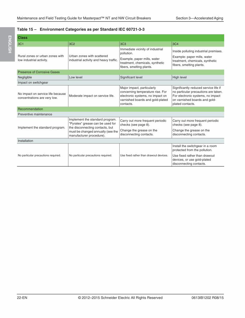
Table 15 – Environment Categories as per Standard IEC 60721-3-3
Class
3C1 3C2 3C3 3C4
Rural zones or urban zones with low industrial activity.
Urban zones with scattered industrial activity and heavy traffic.
Immediate vicinity of industrial pollution.
Example, paper mills, water treatment, chemicals, synthetic fibers, smelting plants.
Inside polluting industrial premises.
Example: paper mills, water treatment, chemicals, synthetic fibers, smelting plants.
Presence of Corrosive Gases
Negligible Low level Significant level High level
Impact on switchgear
No impact on service life because concentrations are very low.
Moderate impact on service life.
Major impact, particularly concerning temperature rise. For electronic systems, no impact on varnished boards and gold-plated contacts.
Significantly reduced service life if no particular precautions are taken. For electronic systems, no impact on varnished boards and gold-plated contacts.
Recommendation
Preventive maintenance
Implement the standard program.
Implement the standard program. "Pyratex“ grease can be used for the disconnecting contacts, but must be changed annually (see the manufacturer procedure).
Carry out more frequent periodic checks (see page 8).
Change the grease on the disconnecting contacts.
Carry out more frequent periodic checks (see page 8).
Change the grease on the disconnecting contacts.
Installation
No particular precautions required. No particular precautions required. Use fixed rather than drawout devices.
Install the switchgear in a room protected from the pollution.
Use fixed rather than drawout devices, or use gold-plated disconnecting contacts.

Section 3—Accelerated Aging Maintenance and Field Testing Guide for Masterpact™ NT and NW Circuit Breakers
23-EN
EN
GL
ISH
© 2012–2015 Schneider Electric All Rights Reserved0613IB1202 R08/15
Operating Conditions
Operating conditions directly affect the service life of switchgear due to the limited electrical and mechanical endurance levels of the various subassemblies. Operating conditions include:
• vibrations,
• the number of operating cycles,
• the interrupted currents.
Table 16 – Vibrations
Influence Appearance Consequences
Premature deterioration of contact surfaces (clusters and main contacts).
Not identifiable. Increased device temperature rise.
Loosening of bolted assemblies. Not identifiable. Increase in mechanical clearance.
Wear of mechanical parts. Not identifiable. Broken springs. Increase in mechanical clearance between parts.
Appearance of fretting corrosion on auxiliary connections.
Not identifiable. Erroneous information or loss of continuity in data or supply, excessive temperature rise.
Breaking of connectors on large
electronic components (e.g. large capacitors).
Not identifiable. Failure of protection function.
Wear of adjustment switches on the trip unit.
Not identifiable. Nuisance tripping or no tripping.
Thresholds
< 0.2 g 0.2 g to <0.5 g 0.5 g to 0.7 g > 0.7 g
Normal condition, no impact on service life.
Reduced service life. Significant increase in incidents. Forbidden for standard devices
Recommendation
Preventive maintenance
Implement the standard program. Carry out more frequent periodic checks (see table).
Carry out more frequent periodic checks (see page 8). Check in particular the tightness of connections.
Installation
No particular precautions required. No particular precautions required. Install switchgear on a rubber mounting bushing.
Install switchgear on a rubber mounting bushing.
Use special devices.
Table 17 – Number of Operating Cycles
Influence Consequences
The number of operating cycles depends directly on the electrical and mechanical endurance of the device.
Device service life depends on the daily number of operating cycles.
Device Service Life (depends on the daily number of operating cycles)
30 cycles per month 60 cycles per month 120 cycles per month
Corresponds to one cycle per day. For a device endurance of 10,000 cycles and an interrupted current of less than 0.4 In, the service life is 30 years.
Corresponds to two cycles per day. For a device endurance of 10,000 cycles and an interrupted current of less than 0.4 In, the service life is 15 years.
Corresponds to four cycles per day. For a device endurance of 10,000 cycles and an interrupted current of less than 0.4 In, the service life is 10 years.
Maintenance and Field Testing Guide for Masterpact™ NT and NW Circuit Breakers Section 3—Accelerated Aging
24-EN
EN
GL
ISH
© 2012–2015 Schneider Electric All Rights Reserved 0613IB1202 R08/15
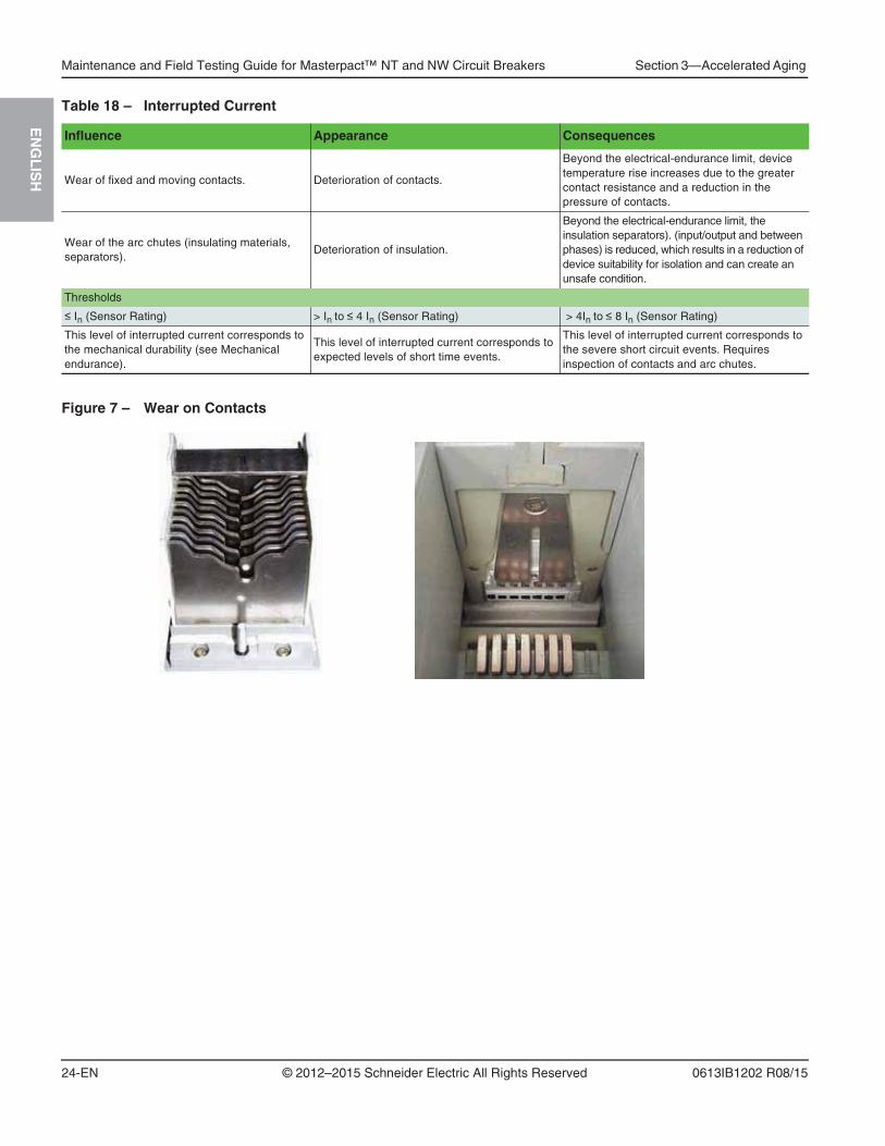
Table 18 – Interrupted Current
Influence Appearance Consequences
Wear of fixed and moving contacts. Deterioration of contacts.
Beyond the electrical-endurance limit, device temperature rise increases due to the greater contact resistance and a reduction in the pressure of contacts.
Wear of the arc chutes (insulating materials, separators).
Deterioration of insulation.
Beyond the electrical-endurance limit, the insulation separators). (input/output and between phases) is reduced, which results in a reduction of device suitability for isolation and can create an unsafe condition.
Thresholds
In (Sensor Rating) > In to 4 In (Sensor Rating) > 4In to 8 In (Sensor Rating)
This level of interrupted current corresponds to the mechanical durability (see Mechanical endurance).
This level of interrupted current corresponds to expected levels of short time events.
This level of interrupted current corresponds to the severe short circuit events. Requires inspection of contacts and arc chutes.
Figure 7 – Wear on Contacts

Section 4—What Must be Maintained Maintenance and Field Testing Guide for Masterpact™ NT and NW Circuit Breakers
25-EN
EN
GL
ISH
© 2012–2015 Schneider Electric All Rights Reserved0613IB1202 R08/15
Section 4— What Must be MaintainedInspect arc chamber/arc chutes, main contacts, spring charging motor, and trip devices after the operations listed in Table 19.
Molded Case The case is an essential element in the circuit breaker. First, it provides a number of safety functions by:
• providing functional insulation between the phases themselves and between the phases and the exposed conductive parts in order to resist transient overvoltages caused by the distribution system
• providing a barrier, preventing direct user contact with live parts
• protecting against the effects of electrical arcs and overpressures caused by short-circuits.
Second, it serves to support the operating mechanism as well as the mechanical and electrical accessories of the circuit breaker.
On the case, there should be:
• no traces of grime (grease), excessive dust or condensation which all reduce insulation
• no signs of burns or cracks which could weaken the case and thus its capacity to withstand short-circuits.
Preventive maintenance for cases consists of:
• a visual inspection of its condition and cleaning with a dry cloth or a vacuum cleaner. All cleaning products with solvents are strictly forbidden.
• Measuring the insulation every five years and following trips due to a short-circuit.
Replace the circuit breaker if there are signs of burns or cracks.
Table 19 – Electrical Operations
Circuit BreakerType
Number of Electrical Operations (Open-Close Cycle)
Arc Chamber
Main Contacts
Spring-Charging Motor (MCH)
Trip Devices (MX/XF)
NW08–NW16 Types N/N1/H/H1/H2/H3/HA/HF
10,000 10,000 12,500 12,500
NW08–NW16 Types L/LF/L1/L1F/HB/HC
3,000 3,000 12,500 12,500
NW20 Types N/H/H1/H2/H3/HA/HF
8,000 8,000 10,000 12,500
NW20 Types L/LF/L1/L1F/HB/HC
3,000 3000 10,000 12,500
NW32 Types H1/H2/H3/HA/HF
NW25-NW30 Types H/L/HB/HF5,000 5,000 10,000 12,500
NW40B (W-Frame)Types H1/H2/H3/HA/HF
5,000 5,000 10,000 12,500
NW40–NW50-NW60 Types H/H2/H3/L/L1/HA/HB/HC/HF
NW32 Type L1
1,500 1,500 5,000 12,500

Maintenance and Field Testing Guide for Masterpact™ NT and NW Circuit Breakers Section 4—What Must be Maintained
26-EN
EN
GL
ISH
© 2012–2015 Schneider Electric All Rights Reserved 0613IB1202 R08/15
Arc Chutes During a short-circuit, the arc chute serves to extinguish the arc and to absorb the high level of energy along the entire path of the short-circuit. It also contributes to arc extinction under rated current conditions. An arc chute that is not in good condition may not be capable of fully clearing the short-circuit and ultimately result in the destruction of the circuit breaker.
The arc chutes must be regularly checked. The fins of the arc chutes may be blackened (due to the gases produced at In) but must not be significantly damaged. What is more, the filters must not be blocked to avoid internal overpressures. Use a vacuum cleaner rather than a cloth to remove dust from the outside of the arc chutes.
Arc Chamber Maintenance
1. Unscrew the mounting screws.
2. Use screwdrivers to lift arc chamber from circuit breaker.
3. Remove arc chamber.
4. Inspect arc chamber. Check that arc chamber body is not broken and that the plates are intact and not significantly burned or melted.
If necessary, replace arc chamber.
Main Contacts The contacts make and break the current under normal conditions (rated current for the installation) and under exceptional conditions (overloads and short-circuits). The contacts are eroded by the many opening and closing cycles and can be particularly deteriorated by short-circuit currents. Worn contacts may result in abnormal temperature rise and accelerate device aging.
It is imperative to remove the arc chutes and visually check contact wear at least once a year and following each short-circuit event.
The contact-wear indicators constitute an absolute minimum value that must not be overrun.
To plan and reduce the number of shutdowns, an electronic wear counter is available with the Micrologic P and H. A visual check is required when the counter reaches 100. When the counter reaches 300, the contacts are worn out and must be replaced.
Figure 8 – Arc Chamber Maintenance
1
43
2

Section 4—What Must be Maintained Maintenance and Field Testing Guide for Masterpact™ NT and NW Circuit Breakers
27-EN
EN
GL
ISH
© 2012–2015 Schneider Electric All Rights Reserved0613IB1202 R08/15
Main Contact Maintenance
1. Remove the arc chambers.
2. Close the circuit breaker and check the condition of the contacts.
If contacts are worn, the circuit breaker block assembly must be replaced.
Table 20 – Contact Wear
Standard Frame Size Interruption Type Poles New Contacts Contacts Need to be Replaced
ANSI
250 A H1/H2/H3/N1 3P
3200–4000 A H2/H3 3P
800–1600 A N1 4P
800–2000 A H1/HA 4P
800–2000 A H2/H3/HF 3P/4P
3200 A H1/HA/H2/H3/HF 4P
3200 A HF 3P/4P
UL
250 A H/N 3P
2000–3000 A L/HB 3P
800–3000 A H/HF 3/4P/4P RHN
800–2000 A N 3P/4P
ANSI
250 A L1/L1F 3P
800–2000 A H1/HA/L1/HC/L1F 3P
3200–5000 A L1/HC 3P
4000–5000 A H2/HA/H3/HF 3P/4P
800–1600 A N1 3P
3200–4000 A H1/HA 3P
UL
250 A L/LF 30
4000–6000 A H/HF3P/4P/4P RHN
4000–6000 A L/HB 3P
800–1600 A L/HB 3P
800–2000 A LF 3P
Maintenance and Field Testing Guide for Masterpact™ NT and NW Circuit Breakers Section 4—What Must be Maintained
28-EN
EN
GL
ISH
© 2012–2015 Schneider Electric All Rights Reserved 0613IB1202 R08/15
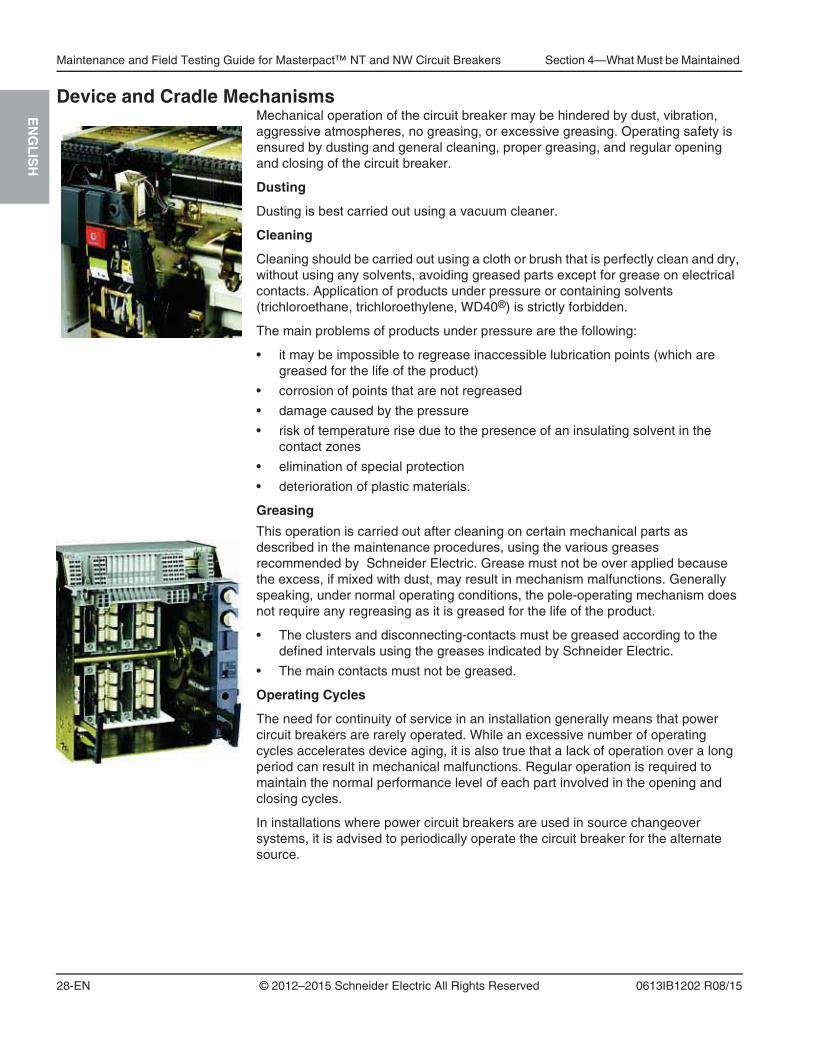
Device and Cradle Mechanisms Mechanical operation of the circuit breaker may be hindered by dust, vibration, aggressive atmospheres, no greasing, or excessive greasing. Operating safety is ensured by dusting and general cleaning, proper greasing, and regular opening and closing of the circuit breaker.
Dusting
Dusting is best carried out using a vacuum cleaner.
Cleaning
Cleaning should be carried out using a cloth or brush that is perfectly clean and dry, without using any solvents, avoiding greased parts except for grease on electrical contacts. Application of products under pressure or containing solvents (trichloroethane, trichloroethylene, WD40®) is strictly forbidden.
The main problems of products under pressure are the following:
• it may be impossible to regrease inaccessible lubrication points (which are greased for the life of the product)
• corrosion of points that are not regreased
• damage caused by the pressure
• risk of temperature rise due to the presence of an insulating solvent in the contact zones
• elimination of special protection
• deterioration of plastic materials.
Greasing
This operation is carried out after cleaning on certain mechanical parts as described in the maintenance procedures, using the various greases recommended by Schneider Electric. Grease must not be over applied because the excess, if mixed with dust, may result in mechanism malfunctions. Generally speaking, under normal operating conditions, the pole-operating mechanism does not require any regreasing as it is greased for the life of the product.
• The clusters and disconnecting-contacts must be greased according to the defined intervals using the greases indicated by Schneider Electric.
• The main contacts must not be greased.
Operating Cycles
The need for continuity of service in an installation generally means that power circuit breakers are rarely operated. While an excessive number of operating cycles accelerates device aging, it is also true that a lack of operation over a long period can result in mechanical malfunctions. Regular operation is required to maintain the normal performance level of each part involved in the opening and closing cycles.
In installations where power circuit breakers are used in source changeover systems, it is advised to periodically operate the circuit breaker for the alternate source.

Section 4—What Must be Maintained Maintenance and Field Testing Guide for Masterpact™ NT and NW Circuit Breakers
29-EN
EN
GL
ISH
© 2012–2015 Schneider Electric All Rights Reserved0613IB1202 R08/15
Auxiliary Circuits
Control Accessories
MX and XF shunt releases are respectively used to remotely open and close the circuit breaker using an electrical order or through a communication network.
The MN undervoltage release is used to break the power circuit if the distribution system voltage drops or fails.
Communicating MX and XF releases and MN releases are continuously supplied and their internal electronic components may suffer accelerated aging if there is temperature rise in the circuit breaker.
Preventive maintenance consists of periodically checking operation at minimum values.
Auxiliary Wiring
Auxiliary wiring is used to transmit orders to the various control devices and to transmit status condition information. Incorrect connections or damaged insulation may result in either non-operation of the circuit breaker or nuisance tripping.
Auxiliary wiring must be regularly checked and replaced as needed, particularly if there are vibrations, high ambient temperatures or corrosive atmospheres.
Indication Contacts
The contacts indicating the status of the circuit-breaker (ON / OFF), of the cradle (CE, CD, CT), a trip due to an electrical fault (SDE), or that the circuit breaker is ready to close (PF) provide the operator with the status information required to react correspondingly. Any incorrect indications may result in erroneous device operation. Contact failure (wear, loose connections) may result from vibrations, corrosion or abnormal temperature rise and preventive maintenance must ensure that contacts correctly conduct or isolate according to their positions.
Spring Charging Motor
The spring charging motor (MCH) automatically recharges the operating-mechanism springs as soon as the circuit breaker is closed. The spring charging motor makes it possible to instantaneously reclose the device following an opening. This function may be indispensable for safety reasons. The charging lever serves simply as a backup means if the auxiliary voltage fails. Periodic checks on the spring charging motor operation and the charging time are required to ensure the device function.

Maintenance and Field Testing Guide for Masterpact™ NT and NW Circuit Breakers Section 4—What Must be Maintained
30-EN
EN
GL
ISH
© 2012–2015 Schneider Electric All Rights Reserved 0613IB1202 R08/15
Electronic Trip UnitIf an electric fault occurs in the installation, the electronic trip unit detects the fault and orders the circuit breaker to open.
Electronic components and circuit boards are sensitive to the environment (ambient temperature, humid and corrosive atmospheres) and to severe operating conditions (magnetic fields, vibrations, etc.). To ensure correct operation, it is necessary to periodically check:
• the chain of action resulting in a trip
• the response time as a function of the level of the fault current.
Use HHTK or FFTK test kits for secondary injection testing or test with primary injection.
Communication Module and Accessories Using the communication bus, the communication option transmits data to a remote site for use by various departments (maintenance, management, production, etc.).
A break in the transmission of data can result in:
• production losses due to unawareness concerning the status of a circuit breaker
• financial losses due to incorrect system management, diagnostic errors, etc.
Periodic checks on the orders (read, write, commands) transmitted by the communication bus are required to maintain a high degree of reliability and confidence in the communication system.
Connections
The connections between the various distribution systems in a switchboard (busbars, cables) and the switchgear are a major source of heat loss. Incorrect tightening may lead to thermal runaway which in turn can provoke damage to the device, the cable insulation, or result in a short-circuit and/or a fire. This type of malfunction is often due to disregard for installation requirements during switchboard assembly.
NOTE: Connections must never use different materials (copper/aluminium).
IFE Module
IFM ModuleI/O Module
Section 4—What Must be Maintained Maintenance and Field Testing Guide for Masterpact™ NT and NW Circuit Breakers
31-EN
EN
GL
ISH
© 2012–2015 Schneider Electric All Rights Reserved0613IB1202 R08/15
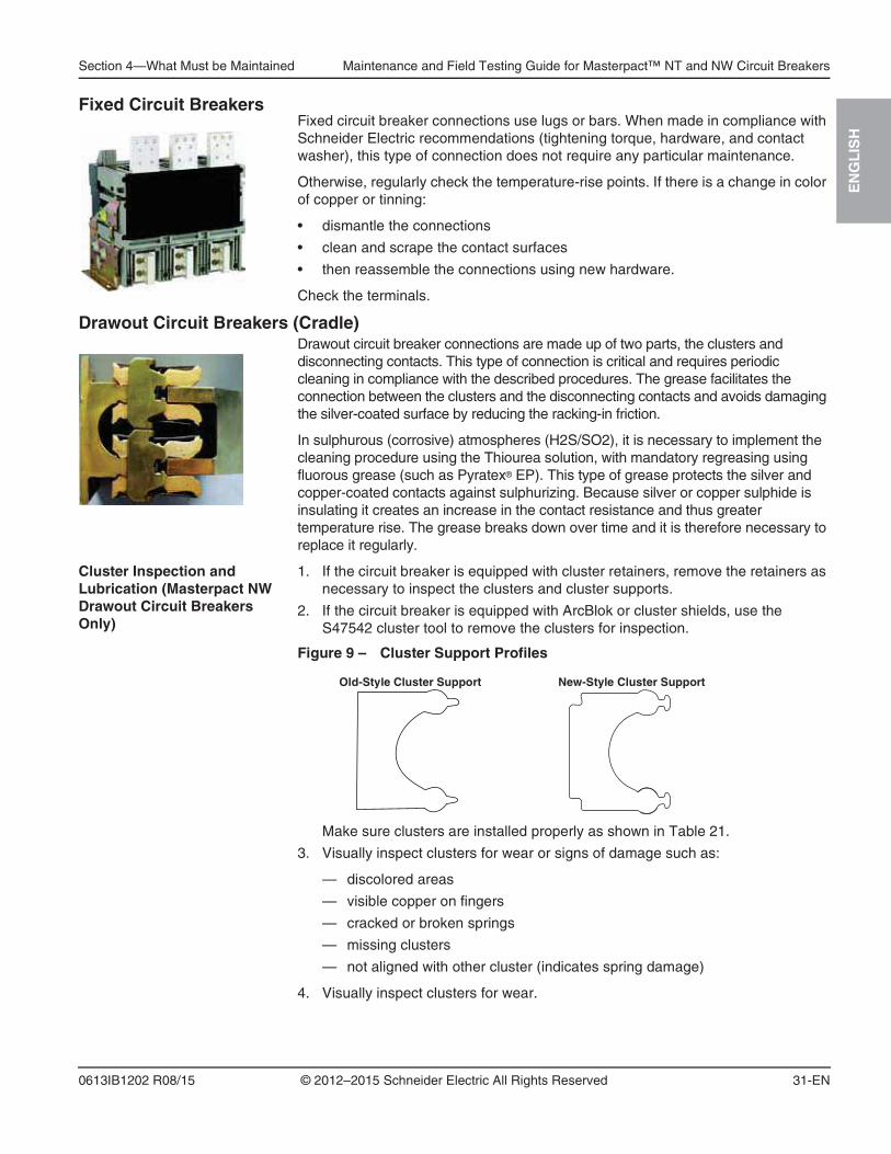
Fixed Circuit BreakersFixed circuit breaker connections use lugs or bars. When made in compliance with Schneider Electric recommendations (tightening torque, hardware, and contact washer), this type of connection does not require any particular maintenance.
Otherwise, regularly check the temperature-rise points. If there is a change in color of copper or tinning:
• dismantle the connections
• clean and scrape the contact surfaces
• then reassemble the connections using new hardware.
Check the terminals.
Drawout Circuit Breakers (Cradle)Drawout circuit breaker connections are made up of two parts, the clusters and disconnecting contacts. This type of connection is critical and requires periodic cleaning in compliance with the described procedures. The grease facilitates the connection between the clusters and the disconnecting contacts and avoids damaging the silver-coated surface by reducing the racking-in friction.
In sulphurous (corrosive) atmospheres (H2S/SO2), it is necessary to implement the cleaning procedure using the Thiourea solution, with mandatory regreasing using fluorous grease (such as Pyratex® EP). This type of grease protects the silver and copper-coated contacts against sulphurizing. Because silver or copper sulphide is insulating it creates an increase in the contact resistance and thus greater temperature rise. The grease breaks down over time and it is therefore necessary to replace it regularly.
Cluster Inspection and Lubrication (Masterpact NW Drawout Circuit Breakers Only)
1. If the circuit breaker is equipped with cluster retainers, remove the retainers as necessary to inspect the clusters and cluster supports.
2. If the circuit breaker is equipped with ArcBlok or cluster shields, use the S47542 cluster tool to remove the clusters for inspection.
Make sure clusters are installed properly as shown in Table 21.
3. Visually inspect clusters for wear or signs of damage such as:
— discolored areas
— visible copper on fingers
— cracked or broken springs
— missing clusters
— not aligned with other cluster (indicates spring damage)
4. Visually inspect clusters for wear.
Figure 9 – Cluster Support Profiles
Old-Style Cluster Support New-Style Cluster Support

Maintenance and Field Testing Guide for Masterpact™ NT and NW Circuit Breakers Section 4—What Must be Maintained
32-EN
EN
GL
ISH
© 2012–2015 Schneider Electric All Rights Reserved 0613IB1202 R08/15
5. For circuit breakers with cluster retainers: check that all clusters have cluster retainers.
NOTE: Circuit breakers with cluster shields or ArcBlok shields do not need the cluster retention kits. Do not attempt to install the cluster retention kits on those circuit breakers.
Cluster Replacement
If Masterpact NW clusters are worn or damaged, new clusters must be installed using cluster positioning tool S47542.
Table 21 – Cluster Configuration
Number of Clusters Per Pole
2 4 6 8 16 24
NOTICEHAZARD OF EQUIPMENT DAMAGE
• If clusters are removed for any reason, clusters must be installed using cluster positioning tool S47542.
• Lubricate clusters as shown in Cluster Lubrication on page 37.
• Do not install anything in the cluster jaw except 3/8 in. (9.5 mm) wide bus bar or Cluster Reset Tool, catalog number CLUSRETOOL.
Failure to follow these instructions can result in equipment damage.
Table 22 – Number of Clusters Per Pole
Type N/N1 H1 HA H / H2 / H3 / HFL / L1 / LF / L1F / HB / NC
V
NW08 2 4 4 4 / 6 / 6 / 4 8
NW12 2 — — 4 8
NW16 6 6 6 6 8
NW20 8 8 8 8 16
NW25 / NW30 — — — 16 16
NW32 — 16 16 16 24
NW40/NW50 — — 24 24 24
NW60 — — — 24 24
V
NW80 / NW12 / NW16 / NW20 / NW25
8
NW30 / NW40 16

Section 4—What Must be Maintained Maintenance and Field Testing Guide for Masterpact™ NT and NW Circuit Breakers
33-EN
EN
GL
ISH
© 2012–2015 Schneider Electric All Rights Reserved0613IB1202 R08/15
— Replace worn or damaged clusters on all cluster configurations.
— Install new clusters (Figure 10, A) using cluster positioning tool S47542 (B).
If clusters and cluster supports are not damaged and the circuit breaker is not equipped with a cluster shield or ArcBlok Shield, you can continue to use the cluster retainer kits. If necessary, retrofit using new cluster supports, finger clusters and cluster shields/ArcBlok shields.
Figure 10 – Cluster Replacement
BA

Maintenance and Field Testing Guide for Masterpact™ NT and NW Circuit Breakers Section 4—What Must be Maintained
34-EN
EN
GL
ISH
© 2012–2015 Schneider Electric All Rights Reserved 0613IB1202 R08/15
Table 23 – Cluster Retainer Kits
Description Frame SizeInterruption Type
Clusters Per Pole
Cluster Retainer Kit Retainer Color
3P 4P Upper Lower
UL489 Listed Masterpact NW Circuit Breaker
800/1600 A
N 2 or 6 CRK2000A3P CRK2000A4P No Color No Color
H 4 or 6 CRK2000A3P CRK2000A4P No Color No Color
L/LF 8 CRK2000A3P N/A No Color No Color
2000 AN/H 8 CRK2000A3P CRK2000A4P No Color No Color
L/LF 16 CRK3000L3P N/A Red Black
2500/3000 AH 16 CRK3200A3P CRK3200A4P Red Black
L 16 CRK3000L3P N/A Red Black
4000/5000/6000 AH 24 CRK6000A3P CRK6000A4P Black Black
L 24 CRK6000A3P N/A Black Black
UL489 Listed Masterpact NW Automatic Switches
800/1600 AHF 4 or 6 CRK2000A3P CRK2000A4P No Color No Color
HB 8 CRK2000A3P N/A No Color No Color
2000 AHF 8 CRK2000A3P CRK2000A4P No Color No Color
HB 16 CRK3000L3P N/A Red Black
2500/3000 AHF 16 CRK3200A3P CRK3200A4P Red Black
HB 16 CRK3000L3P N/A Red Black
4000/5000/6000 AHF 24 CRK6000A3P CRK6000A4P Black Black
HB 24 CRK6000A3P N/A Black Black
ANSI C37 Certified Masterpact NW Circuit Breaker
800/1600 A
N1 2 or 6 CRK2000A3P CRK2000A4P No Color No Color
H1/H2/H3 4 or 6 CRK2000A3P CRK2000A4P No Color No Color
L1/L1F 8 CRK2000A3P N/A No Color No Color
2000 AH1/H2/H3 8 CRK2000A3P CRK2000A4P No Color No Color
L1/L1F 16 CRK3000L3P N/A Red Black
3200 AH1/H2/H3 16 CRK3200A3P CRK3200A4P Red Black
L1 24 CRK6000A3P N/A Black Black
4000/5000 AH2/H3 24 CRK6000A3P CRK6000A4P Black Black
L1 24 CRK6000A3P N/A Black Black
ANSI C37 Certified Masterpact NW Non-Automatic Switches
800/1600 A HA 4 or 6 CRK2000A3P CRK2000A4P No Color No Color
2000 A HA 8 CRK2000A3P CRK2000A4P No Color No Color
3200 A HA 16 CRK3200A3P CRK3200A4P Red Black
4000/5000 A HA 24 CRK6000A3P CRK6000A4P Black Black
ANSI C37 Certified Masterpact NW Automatic Switches
800/1600 AHF 4 or 6 CRK2000A3P CRK2000A4P No Color No Color
HC 8 CRK2000A3P N/A No Color No Color
2000 AHF 8 CRK2000A3P CRK2000A4P No Color No Color
HC 16 CRK3000L3P N/A Red Black
3200 AHF 16 CRK3200A3P CRK3200A4P Red Black
HC 24 CRK6000A3P N/A Black Black
4000/5000 AHF 24 CRK6000A3P CRK6000A4P Black Black
HC 24 CRK6000A3P N/A Black Black
Cluster Retainer Clip All All — CRCLIP — — —

Section 4—What Must be Maintained Maintenance and Field Testing Guide for Masterpact™ NT and NW Circuit Breakers
35-EN
EN
GL
ISH
© 2012–2015 Schneider Electric All Rights Reserved0613IB1202 R08/15
NOTE: Cluster retainer clip cannot be reused. Use new cluster retainer clip, part number CRCLIP.
1. Replace worn or damaged clusters on all cluster configurations except lower clusters on 16 and 24 cluster configurations.
a. Remove lower connector plate (Figure 11, A), if present. Retain plate, screws and washers.
b. Remove cluster retainer clip (B) and cluster retainer (C), if equipped. Discard cluster retainer clip. Remove worn or damaged clusters.
c. Install new clusters (D) using cluster positioning tool S47542 (E).
d. Secure clusters using cluster retainer (C) and new cluster retainer clip (B). See Table 23 for correct cluster retention kit and cluster retainer color.
e. Replace lower connector plate (A), if previously removed. Secure using previously-retained screws and washers. Torque screws to 17.7 lb-in. (2 N•m).
DANGERHAZARD OF ELECTRIC SHOCK, EXPLOSION OR ARC FLASH
Install the correct cluster retainer identified by color depending on circuit breaker size and type. See Table 23.
Failure to follow these instructions will result in death or serious injury.
Figure 11 – Cluster Replacement
C
ED
B
A

Maintenance and Field Testing Guide for Masterpact™ NT and NW Circuit Breakers Section 4—What Must be Maintained
36-EN
EN
GL
ISH
© 2012–2015 Schneider Electric All Rights Reserved 0613IB1202 R08/15
2. Replace worn or damaged clusters on lower set of clusters on 16 and 24 cluster configurations (Figure 12, A):
a. Remove lower connector plate (B), if present. Retain plate, screws and washers.
b. Remove cluster retainer clip (C) and cluster retainer (D), if equipped. Discard cluster retainer clip. Remove all clusters, discard worn or damaged clusters.
c. Slide cluster retainer (D) through two clusters until bottom of cluster retainer is even with bottom of lower cluster. See Table 23 for correct cluster retainer kit and color.
d. Install the two clusters and cluster retainer (E) on top two notches of cluster support (F) using cluster positioning tool S47542 (G).
e. Install the third cluster (H) on bottom notch of cluster support (F) using cluster positioning tool S47542 (G).
f. Slide cluster retainer (J) through third cluster and secure using new cluster retainer clip (K).
g. Repeat for clusters on other side of cluster support.
h. Replace lower connector plate (B), if previously removed. Secure using previously-retained screws and washers. Torque screws to 17.7 lb-in. (2 N•m).
DANGERHAZARD OF ELECTRIC SHOCK, EXPLOSION OR ARC FLASH
Install the correct cluster retainer identified by color depending on circuit breaker size and type. See Table 23.
Failure to follow these instructions will result in death or serious injury.

Section 4—What Must be Maintained Maintenance and Field Testing Guide for Masterpact™ NT and NW Circuit Breakers
37-EN
EN
GL
ISH
© 2012–2015 Schneider Electric All Rights Reserved0613IB1202 R08/15
Cluster Lubrication
Use grease kit (catalog number S48899) to lubricate cluster jaws as shown in Figure 13.
NOTE: Remove any existing grease from cluster assembly before applying new grease to clusters.
Figure 12 – Cluster Replacement
B
A
C
FE
D
G
F
G
J
K
H
NOTICEHAZARD OF EQUIPMENT DAMAGE
Inspect the cluster for lubrication when the circuit breaker is removed from the cradle.
Failure to follow these instructions can result in equipment damage.
Figure 13 – Cluster Grease Application

Maintenance and Field Testing Guide for Masterpact™ NT and NW Circuit Breakers Section 4—What Must be Maintained
38-EN
EN
GL
ISH
© 2012–2015 Schneider Electric All Rights Reserved 0613IB1202 R08/15
Cradle Stab Lubrication
The cradle stabs must be inspected and lubricated when the cradle is first installed and again during maintenance periods after all power has been disconnected.
Confirm that both sides of stab are coated with lubricant. If necessary, use grease kit (catalog number S48899) to lubricate stab.
NOTE: Remove any existing grease from cradle stabs before applying new grease to them.
DANGERHAZARD OF ELECTRIC SHOCK, EXPLOSION OR ARC FLASH
• Apply appropriate personal protective equipment (PPE) and follow safe electrical work practices. See NFPA 70E, CSA Z462, or NOM-029-STPS.
• This equipment must be installed and serviced only by qualified electrical personnel.
• Turn off all power supplying this equipment before working on or inside equipment.
• Always use a properly rated voltage sensing device to confirm power is off.
• Replace all devices, doors and covers before turning on power to this equipment.
Failure to follow these instructions will result in death or serious injury.
Figure 14 – Cradle Stab Grease Application

Section 5—Troubleshooting Maintenance and Field Testing Guide for Masterpact™ NT and NW Circuit Breakers
39-EN
EN
GL
ISH
© 2012–2015 Schneider Electric All Rights Reserved0613IB1202 R08/15
Section 5— TroubleshootingTable 24 – Troubleshooting and Solutions
Issue Probable causes Solutions
Circuit breaker cannot be closed locally or remotely.
1. Circuit breaker padlocked or keylocked in the “open” position.
2. Circuit breaker interlocked mechanically in a source changeover system.
3. Circuit breaker not completely connected. 4. The reset button signaling a fault trip has not
been reset.5. Stored energy mechanism not charged.
6. MX opening shunt release permanently supplied with power.
7. MN undervoltage release not supplied with power.
8. XF closing release continuously supplied with power, but circuit breaker not “ready to close” (XF not wired in series with PF contact).
9. Permanent trip order of a Micrologic P or H trip unit with minimum voltage and minimum frequency protection in Trip mode and the trip unit powered.
1. Disable the locking function.
2. Check the position of the other circuit breaker in the changeover system. Modify the situation to release the interlock.
3. Complete racking in (connection) of the circuit breaker. 4. Clear the fault.
Push the reset button on the front of the circuit breaker. 5. Charge the mechanism manually
If it is equipped with an MCH spring charging motor, check the supply of power to the motor. If the problem persists, replace the spring charging motor (MCH).
6. There is an opening order. Determine the origin of the order. The order must be cancelled before the circuit breaker can be closed.
7. There is an opening order. Determine the origin of the order. Check the voltage and the supply circuit (U > 0.85 Un). If the problem persists, replace the undervoltage release.
8. Cut the supply of power to the XF closing release. then send the closing order again via the XF, but only if the circuit breaker is “ready to close”.
9. Disable these protection functions on the Micrologic P or H trip unit.
Circuit breaker cannot be closed remotely but can be opened locally using the closing pushbutton.
Closing order not executed by the XF closing release.
Check the voltage and the supply circuit (0.85 - 1.1 Un). If the problem persists, replace the XF release.
Unexpected tripping without activation of the reset button signaling a fault trip.
1. MN undervoltage release supply voltage too low.
2. Load-shedding order sent to the MX opening release by another device.
3. Unnecessary opening order from the MX opening release.
1. Check the voltage and the supply circuit (U > 0.85 Un).
2. Check the overall load on the distribution systemIf necessary, modify the settings of devices in the installation.
3. Determine the origin of the order.
Unexpected tripping with activation of the reset button signaling a fault trip.
A fault is present:
• overload• earth fault • short-circuit detected by the trip unit
Determine and clear the causes of the fault.
Check the condition of the circuit breaker before putting it back into service.
Instantaneous opening after each attempt to close the circuit breaker with activation of the reset button signaling a fault trip.
1. Thermal memory.
2. Transient overcurrent when closing.
3. Closing on a short circuit.
1. See the user manual of the trip unit.Press the reset button.
2. Modify the distribution system or the trip unit settings.Check the condition of the circuit breaker before putting it back into service.Press the reset button.
3. Clear the fault.Check the condition of the circuit breaker before putting it back into service.Press the reset button.
Continued on next page

Maintenance and Field Testing Guide for Masterpact™ NT and NW Circuit Breakers Section 5—Troubleshooting
40-EN
EN
GL
ISH
© 2012–2015 Schneider Electric All Rights Reserved 0613IB1202 R08/15
Circuit breaker cannot be opened remotely, but can be opened locally.
1. Opening order not executed by the MX opening release.
2. Opening order not executed by the MN undervoltage release.
1. Check the voltage and the supply circuit (0.7 - 1.1 Un). If the problem persists, replace the MX release.
2. Drop in voltage insufficient or residual voltage (> 0.35 Un) across the terminals of the undervoltage release. If the problem persists, replace the MN release.
Circuit breaker cannot be opened locally.
Operating mechanism malfunction or welded contacts.
Contact a Schneider Electric service center.
Circuit breaker can be reset locally but not remotely.
Insufficient supply voltage for the MCH spring charging motor.
Check the voltage and the supply circuit (0.7 - 1.1 Un). If the problem persists, replace the MCH release.
Nuisance tripping of the circuit breaker with activation of the reset button signaling a fault trip.
Reset button not pushed in completely. Push the reset button in completely.
Impossible to insert the crank in connected, test or disconnected position.
A padlock or keylock is present on the cradle or a door interlock is present.
Disable the locking function.
Impossible to turn the crank. The reset button has not been pressed. Press the reset button
Circuit breaker cannot be removed from cradle.
1. Circuit breaker not in disconnected position.
2. The rails are not completely out.
1. Turn the crank until the circuit breaker is in disconnected position and the reset button out. Remove crank and store it.
2. Pull the rails all the way out.
Circuit breaker cannot be connected (racked in).
1. Cradle/circuit breaker mismatch protection.
2. The safety shutters are locked.3. The disconnecting-contact clusters are
incorrectly positioned.4. Cradle locked in disconnected position.5. The reset button has not been pressed,
preventing rotation of the crank. 6. The circuit breaker has not been sufficiently
inserted in the cradle.
1. Check that the cradle corresponds with the circuit breaker.
2. Remove the lock(s).3. Reposition the clusters.
4. Disable the cradle locking function.5. Press the reset button.
6. Insert the circuit breaker completely so that it is engaged in the racking mechanism.
Circuit breaker cannot be locked in disconnected position.
1. The circuit breaker is not in the right position.
2. The crank is still in the cradle.
1. Check the circuit breaker position by making sure the reset button is out.
2. Remove the crank and store it.
Circuit breaker cannot be locked in connected, test or disconnected position.
1. Check that locking in any position is enabled. 2. The circuit breaker is not in the right position.
3. The crank is still in the cradle.
1. Contact a Schneider service center.2. Check the circuit breaker position by making sure the
reset button is out.3. Remove the crank and store it.
The crank cannot be inserted to connect or disconnect the circuit breaker.
The rails are not completely in. Push the rails all the way in.
The right-hand rail (cradle alone) or the circuit breaker cannot be drawn out.
The crank is still in the cradle. Remove the crank and store it.
Continued on next page
Table 24 – Troubleshooting and Solutions (continued)
Issue Probable causes Solutions

Section 5—Troubleshooting Maintenance and Field Testing Guide for Masterpact™ NT and NW Circuit Breakers
41-EN
EN
GL
ISH
© 2012–2015 Schneider Electric All Rights Reserved0613IB1202 R08/15
Circuit breaker cannot be closed locally or remotely.
Circuit breaker padlocked or keylocked in the “open” position.
Disable the locking function.
Circuit breaker interlocked mechanically in a source changeover system.
• Check the position of the other circuit breaker in the changeover system.
• Modify the situation to release the interlock.
Circuit breaker not completely connected. • Terminate racking in (connection) of the circuit
breaker.
The reset button signaling a fault trip has not been reset.
• Clear the fault.• Push the reset button on the front of the circuit
breaker.
Stored energy mechanism not charged.
• Charge the mechanism manually. • If it is equipped with a an MCH spring charging
motor, check the supply of power to the motor. If the problem persists, replace the spring charging motor (MCH).
MX opening shunt release permanently supplied with power.
• There is an opening order. Determine the origin of the order.
• The order must be cancelled before the circuit breaker can be closed.
MN undervoltage release not supplied with power.
• There is an opening order. Determine the origin of the order.
• Check the voltage and the supply circuit (U > 0.85 Un). If the problem persists, replace the release.
XF closing release continuously supplied with power, but circuit breaker not “ready to close” (XF not wired in series with PF contact).
Cut the supply of power to the XF closing release, then send the closing order again via the XF, but only if the ‘circuit breaker is “ready to close.”
Permanent trip order in the presence of a Micrologic P or H trip unit with minimum voltage and minimum frequency protection in Trip mode and the trip unit powered.
Disable these protection functions on the Micrologic P or H trip unit.
Circuit breaker cannot be closed remotely but can be opened locally using the closing pushbutton.
Closing order not executed by the XF closing release
• Check the voltage and the supply circuit (0.85 - 1.1 Un). • If the problem persists, replace the XF release.
Unexpected tripping without activation of the reset button signaling a fault trip.
MN undervoltage release supply voltage too low. Check the voltage and the supply circuit (U > 0.85 Un).
Load-shedding order sent to the MX opening release by another device.
• Check the overall load on the distribution system• If necessary, modify the settings of devices in the
installation
Unnecessary opening order from the MX opening release.
Determine the origin of the order
Unexpected tripping with activation of the reset button signaling a fault trip.
A fault is present:
• overload• earth fault • short-circuit detected by the trip unit
• Determine and clear the causes of the fault.• Check the condition of the circuit breaker before
putting it back into service
Instantaneous opening after each attempt to close the circuit breaker with activation of the reset button signaling a fault trip.
Thermal memory. • See the user manual of the trip unit.• Press the reset button.
Transient overcurrent when closing.
• Modify the distribution system or the control-unit settings.
• Check the condition of the circuit breaker before putting it back into service.
• Press the reset button.
Closing on a short circuit.
• Clear the fault.• Check the condition of the circuit breaker before
putting it back into service.• Press the reset button.
Continued on next page
Table 24 – Troubleshooting and Solutions (continued)
Issue Probable causes Solutions

Maintenance and Field Testing Guide for Masterpact™ NT and NW Circuit Breakers Section 5—Troubleshooting
42-EN
EN
GL
ISH
© 2012–2015 Schneider Electric All Rights Reserved 0613IB1202 R08/15
Circuit breaker cannot be opened remotely, but can be opened locally.
Opening order not executed by the MX opening release.
Check the voltage and the supply circuit (0.7 - 1.1 Un). If the problem persists, replace the MX release.
Opening order not executed by the MN undervoltage release.
Drop in voltage insufficient or residual voltage (> 0.35 Un) across the terminals of the undervoltage release. If the problem persists, replace the MN release.
Circuit breaker cannot be opened locally.
Operating mechanism malfunction or welded contacts.
Contact a Schneider Electric service center.
Circuit breaker can be reset locally but not remotely.
Insufficient supply voltage for the MCH spring charging motor.
Check the voltage and the supply circuit (0.7 - 1.1 Un). If the problem persists, replace the MCH release.
Nuisance tripping of the circuit breaker with activation of the reset button signaling a fault trip.
Reset button not pushed-in completely. Push the reset button in completely.
Impossible to insert the crank in connected, test or disconnected position.
A padlock or keylock is present on the cradle or a door interlock is present.
Disable the locking function.
Impossible to turn the crank. The reset button has not been pressed. Press the reset button.
Circuit breaker cannot be removed from cradle.
Circuit breaker not in disconnected position.Turn the crank until the circuit breaker is in disconnected position and the reset button out.
The rails are not completely out. Pull the rails all the way out.
Circuit breaker cannot be connected (racked in)
Cradle/circuit breaker mismatch protection.Check that the cradle corresponds with the circuit breaker.
The safety shutters are locked. Remove the lock(s).
The disconnecting-contact clusters are incorrectly positioned.
Reposition the clusters.
Cradle locked in disconnected position. Disable the cradle locking function.
The reset button has not been pressed, preventing rotation of the crank.
Press the reset button.
The circuit breaker has not been sufficiently inserted in the cradle.
Insert the circuit breaker completely so that it is engaged in the racking mechanism.
Circuit breaker cannot be locked in disconnected position
The circuit breaker is not in the right position.Check the circuit breaker position by making sure the reset button is out.
The crank is still in the cradle. Remove the crank and store it.
Circuit breaker cannot be locked in connected, test or disconnected position
Check that locking in any position is enabled. Contact a Schneider service center.
The circuit breaker is not in the right position.Check the circuit breaker position by making sure the reset button is out.
The crank is still in the cradle. Remove the crank and store it.
The crank cannot be inserted to connect or disconnect the circuit breaker
The rails are not completely in. Push the rails all the way in.
The right-hand rail (cradle alone) or the circuit breaker cannot be drawn out
The crank is still in the cradle. Remove the crank and store it.
Table 24 – Troubleshooting and Solutions (continued)
Issue Probable causes Solutions

Section 6—Testing Maintenance and Field Testing Guide for Masterpact™ NT and NW Circuit Breakers
43-EN
EN
GL
ISH
© 2012–2015 Schneider Electric All Rights Reserved0613IB1202 R08/15
Section 6— Testing
Procedures
Visual Inspections During Operation
While circuit breaker is energized:
1. Verify circuit breaker application and rating.
Make sure that the circuit breaker is properly applied within labeled voltage, ampere rating, maximum current interrupting ratings and to Company recommendations. Compare the circuit breaker faceplate data to the installation drawings. Verify trip unit settings on Micrologic electronic-trip circuit breakers with the coordination study. After completing inspection and maintenance procedures, insure that all trip unit settings for all functions are set according to the coordination study.
2. Check for overheating while equipment is energized.
While the circuit breaker is normally operating, under load and at operating temperature, check the exposed, accessible, insulated face of the circuit breaker and adjacent dead front surfaces of the enclosure for overheating. To do this, use an infrared temperature probe to check the temperature. If the temperature exceeds 140°F (60°C), the cause should be investigated.
Allow initially energized circuit breaker at least three hours to reach operating temperature. Compare the surface temperature of individual circuit breakers with the surface temperature of other circuit breakers in the installation. Circuit breaker surface temperatures vary according to loading, position in the panelboard and ambient temperature. If the surface temperature of a circuit breaker is considerably higher than adjacent circuit breakers, the cause should be investigated.
Thermographic inspection methods may also be used to evaluate overheating with equipment energized (see Thermographic Inspection, page 44).
3. Check for cracks in the circuit breaker case.
Any circuit breaker with a cracked case should be replaced because its ability to withstand short-circuit interruption stresses is reduced.
4. Inspect the enclosure.
The enclosure should be clean and dry. All covers and trim pieces should be in place.
DANGERHAZARD OF ELECTRIC SHOCK, EXPLOSION, OR ARC FLASH
• Apply appropriate personal protective equipment (PPE) and follow safe electrical work practices. See NFPA 70E, CSA Z462, or NOM-029-STPS.
• This equipment must only be installed and serviced by qualified electrical personnel.
• Take precautions to ensure that no accidental contact is made with live components during this check.
Failure to follow these instructions will result in death or serious injury.

Maintenance and Field Testing Guide for Masterpact™ NT and NW Circuit Breakers Section 6—Testing
44-EN
EN
GL
ISH
© 2012–2015 Schneider Electric All Rights Reserved 0613IB1202 R08/15
Thermographic Inspection
Infrared thermographic inspection techniques may be useful in evaluating the operating condition of circuit breakers and terminations. Comparison to stored infrared thermographic images may be useful for the preventive maintenance of circuit breakers and end-use equipment. The actual amount of heat emitted is a function of both load current and ambient conditions. Interpretation of infrared survey requires experience and training in this type of inspection.
Allow initially energized circuit breakers at least three hours to reach operating temperature. Compare the thermographic images of individual circuit breakers to previously stored images of the same circuit breakers.
Performance Tests
Do the performance tests in the order given to maximize the accuracy of the test results.
NOTE: Never do the contact resistance test before doing the instantaneous primary injection testing. The primary injection testing will ensure the contacts are clear of resistive films, oxidation and foreign material.
The following tests are intended to verify that a circuit breaker is operating properly. Precisely controlled factory testing conditions are used to establish the characteristic trip curves. If field test results fall outside the characteristic trip curve tolerance band, carefully evaluate the test conditions and methods for accuracy.
DANGERHAZARD OF ELECTRIC SHOCK, EXPLOSION, OR ARC FLASH
Only qualified electrical workers with training and experience on low-voltage circuits should perform thermographic inspections. These workers must understand the hazards involved in working with or near low-voltage equipment. Perform such work only after reading this complete set of instructions.
Failure to follow these instructions will result in death or serious injury.
DANGERHAZARD OF ELECTRIC SHOCK, EXPLOSION, OR ARC FLASH
• Apply appropriate personal protective equipment (PPE) and follow safe electrical work practices. See NFPA 70E, CSA Z462, or NOM-029-STPS.
• This equipment must only be installed and serviced by qualified electrical personnel.
• Turn off all power supplying this equipment before working on or inside equipment.
• Always use a properly rated voltage sensing device to confirm power is off.
• Replace all devices, doors and covers before turning on power to this equipment.
• Do not touch the circuit breaker terminals or the test leads while the circuit breaker is being tested.
Failure to follow these instructions will result in death or serious injury.

Section 6—Testing Maintenance and Field Testing Guide for Masterpact™ NT and NW Circuit Breakers
45-EN
EN
GL
ISH
© 2012–2015 Schneider Electric All Rights Reserved0613IB1202 R08/15
When questionable conditions or results are observed during inspection and performance tests, consult the local field sales office. Circuit breakers with accessories or factory modifications may require special investigation. If it is necessary to return a circuit breaker to the manufacturing facility, use proper packaging and packing materials to avoid shipping damage.
Dielectric Testing Masterpact Circuit Breakers with Micrologic P or H Trip Systems
Dielectric tests (high potential, insulation resistance or Megger tests) are used to ensure the proper isolation and insulation between phases and between each phase and ground. The equipment used to conduct these tests creates a high-potential voltage (thousands of volts) to verify dielectric or insulation integrity.
The rating plug on Micrologic P and H trip units connect/disconnect the trip unit with the voltage connections in the circuit breaker. Before conducting any high-voltage tests on circuit breakers with Micrologic P and H trip units, remove the rating plug as shown
NOTE: Only Micrologic P and H trip units have phase voltage connections into the trip unit. For other types of trip units, it is not necessary to remove the rating plug prior to dielectric testing.
1. Open switch cover (Figure 15, A).
2. Unscrew rating plug mounting screw (B).
3. Remove rating plug (C).
NOTICEHAZARD OF EQUIPMENT DAMAGE
• Dielectric tests (high potential, insulation resistance, or Megger tests) may damage Micrologic P and H trip units.
• Remove rating plug from trip unit prior to testing.
• Replace trip unit if rating plug was not removed during tests or if trip unit was exposed to more than 700 Vac.
Failure to follow these instructions can result in equipment damage.
Figure 15 – Removing Rating Plug
CB
A

Maintenance and Field Testing Guide for Masterpact™ NT and NW Circuit Breakers Section 6—Testing
46-EN
EN
GL
ISH
© 2012–2015 Schneider Electric All Rights Reserved 0613IB1202 R08/15
Insulation Resistance Test
Severe environmental conditions can reduce the dielectric strength of molded case circuit breakers. Check insulation resistance during electrical system testing.
To check the insulation resistance, perform the following steps:
1. De-energize and isolate the circuit breaker:
2. Clean the circuit breaker as described earlier.
3. Using a megohmmeter with a capacity of 500–1000 Vdc, apply voltage from:
a. Each phase-to-ground with the circuit breaker on (circuit breaker contacts closed).
b. Phase-to-phase with the circuit breaker on (circuit breaker contacts closed).
c. Between each line and load terminal with the circuit breaker off (circuit breaker contacts open).
4. Record resistance values. Resistance values of less than one megohm (1,000,000 ohm) should be investigated.
After testing is complete, replace rating plug if previously removed:
1. Replace rating plug (Figure 16, A).
2. Tighten rating plug mounting screw (B).
NOTE: If the rating plug is not installed, the circuit breaker will default to a long-time pickup setting of 0.4 x the sensor (In) and some of the advanced functions will not be operable.
NOTICEHAZARD OF EQUIPMENT DAMAGE
Do not apply test voltage to control circuits or accessory terminals; damage to electronic and/or low-voltage components can result.
Failure to follow these instructions can result in equipment damage.
Figure 16 – Replacing Rating Plug
BA
2.6 lb-in.(0.3 N•m)

Section 6—Testing Maintenance and Field Testing Guide for Masterpact™ NT and NW Circuit Breakers
47-EN
EN
GL
ISH
© 2012–2015 Schneider Electric All Rights Reserved0613IB1202 R08/15
Micrologic Trip Unit Checks
Circuit breakers with Micrologic trip units can have their trip unit operation tested with secondary injection testing using the one of the available test kits. (See page 58 for test kits.)
Secondary injection testing does not test the current transformers and connections. Primary injection testing can be used to ensure that all trip system connections have been correctly made.
If the circuit breaker is tested by the primary injection method, the Powerlogic™ system can remain connected to the circuit breaker during testing without affecting the results.
NOTE: Testing a circuit breaker connected to a Powerlogic system causes the Powerlogic system to react as if the circuit breaker were experiencing the actual faults.
Procedure to Defeat Zone-Selective Interlocking
Zone-selective interlocking is a method of communication between electronic-trip overcurrent protective devices. Zone-selective interlocking allows interlocked devices at different levels to work together as a system in which a short circuit or ground fault is isolated and cleared with minimum time delay. The purpose of defeating zone-selective interlocking is to verify the characteristics of the specific circuit breaker short-time and ground-fault trip delay functions. For test purposes, zone-selective interlocking can be inhibited on Masterpact circuit breakers equipped with Micrologic trip units by using the Hand-Held or Full-Function Test Kit.
Secondary Injection Testing
Field installation of a trip unit requires secondary injection testing with a Full-Function Test Kit. This will ensure that the newly-installed trip unit is functioning properly. The test will require opening and closing the circuit breaker. Follow the procedures outlined in the instruction bulletins shipped with the circuit breaker and the Full-Function Test Kit.
1. Make sure the circuit breaker is isolated from all upstream and downstream devices.
2. Perform secondary injection testing as outlined in the instruction bulletin shipped with the full-function test kit. Verify that all applicable trip unit functions are operating properly.
3. Repeat step 2 with the circuit breaker in the open position.
NOTE: The test kit states that the circuit breaker should be closed when performing the test. Do not close the circuit breaker for this step.
4. If any test fails, do not put the circuit breaker into service and contact the local sales office for factory authorization service.

Maintenance and Field Testing Guide for Masterpact™ NT and NW Circuit Breakers Section 6—Testing
48-EN
EN
GL
ISH
© 2012–2015 Schneider Electric All Rights Reserved 0613IB1202 R08/15
Primary Injection Testing
Primary injection testing can be used to ensure that all trip system connections have been correctly made.
NOTE: Secondary injection testing continues to be the Schneider Electric preferred method for testing circuit breakers. Improper primary injection testing can cause damage to the circuit breakers. Failure to conduct primary injection testing in the proper manner could result in circuit breakers passing testing, while ultimately damaging the integrity of the circuit breaker long term.
1. If performing primary injection testing on drawout circuit breakers, connect circuit breaker to power supply using primary injection test kits.
.
NOTICEHAZARD OF EQUIPMENT DAMAGE
• Circuit breakers are heavy and can be damaged with improper handling. Use care when handling and transporting circuit breakers to test equipment.
• Make connection to the circuit breaker carefully using rated cable and appropriate connection methods. Do not use clamps or other methods that can score or otherwise damage the finish of the connectors.
• When connecting a drawout-type circuit breaker, use approved primary injection test kit. Adjust circuit breaker position so circuit breaker clusters align with the primary injection test kit.
Failure to follow these instructions can result in equipment damage.
Table 25 – Primary Injection Test Kit
Circuit Breaker Type Power Supply Test Kit Required
Masterpact NW without ArcBlok or Cluster Shields
Phoenix® ULW10025
MultiAmp ® ULW10026
Masterpact NW with ArcBlok or Cluster Shields
Phoenix® ULW10025 and Primary Injection Bumper Kit 84958
MultiAmp ®ULW10026 and Primary Injection Bumper Kit 84958
Masterpact NT Phoenix or MulitAmp ULW10027
PowerPact Phoenix or MulitAmp ULW10027
All Types Other Than Phoenix or MultiAmp Contact Field Office

Section 6—Testing Maintenance and Field Testing Guide for Masterpact™ NT and NW Circuit Breakers
49-EN
EN
GL
ISH
© 2012–2015 Schneider Electric All Rights Reserved0613IB1202 R08/15
a. Install primary injection test kit following instructions shipped with the test kit.
b. Adjust height of the circuit breaker so the stop (A, above) between the top and bottom plates of the test kit is between the top and bottom connectors of the circuit breaker when it is in the connected positions.
c. Align the circuit breaker so that the clusters on the circuit breaker phase being tested line up with the connectors with the primary injection test kit.
d. Use grease kit, catalog number S48899, to lubricate connectors. Do not install anything in the cluster jaw except approved test kit.
NOTE: Remove any existing grease from cluster assembly before applying new grease to clusters.
2. If performing primary injection testing on fixed circuit breakers, connect circuit breaker to power supply using rated cable and appropriate connection method.
NOTE: Wide-construction circuit breakers only—When primary injection testing a circuit breaker with six bus connectors, current is injected into phases as shown in Figure 18. Do not inject current into outside busses.
Figure 17 – Masterpact NW Primary Injection Test Assembly
Phases
Top of Circuit Breaker
A B C
Top of Circuit Breaker
A B C
AA
Primary Injection Test Assembly for Circuit Breakers without ArcBlok or Cluster Shields
Primary Injection Test Assembly with Primary Injection Bumper (Kit 84958) for Circuit Breakers with ArcBlok or Cluster Shields

Maintenance and Field Testing Guide for Masterpact™ NT and NW Circuit Breakers Section 6—Testing
50-EN
EN
GL
ISH
© 2012–2015 Schneider Electric All Rights Reserved 0613IB1202 R08/15
3. Record each of the original trip unit switch settings. (Settings must be reset after testing is complete.)
4. Set the long-time pickup (Ir) switch (A) to the minimum setting.
a. For ground-fault and/or zone-selective interlocked trip units, use the hand-held or full-function test kit to inhibit ground-fault and zone-selective interlocking functions.
b. If an auxiliary power supply is being used for the Micrologic trip unit, disconnect the auxiliary power supply.
c. Find the primary injection current needed by multiplying the long-time pickup current (long-time pickup setting Ir x sensor plug In) x 125% (i.e. Ir x In x 1.25).
d. Inject primary current into A-phase and monitor the overload indicator light. Verify that the overload indicator light (A) lights between 105% and 120% of the Ir x In value.
e. Repeat for all phases and neutral (if applicable).
f. If overload indicator light does not light correctly, check all trip unit connections and test setup. If unit still fails primary injection testing, contact the local sales office.
Figure 18 – Wide-Construction Circuit Breakers
Primary Injection Test
Top of Circuit Breaker
A B C
Figure 19 – Record Switch Settings
A A AMicrologic 3.0A Micrologic 5.0A Micrologic 6.0ATrip Unit Trip Unit Trip Unit
Figure 20 – Overload Indicator Light
A A AMicrologic 3.0A Micrologic 5.0A Micrologic 6.0ATrip Unit Trip Unit Trip Unit

Section 6—Testing Maintenance and Field Testing Guide for Masterpact™ NT and NW Circuit Breakers
51-EN
EN
GL
ISH
© 2012–2015 Schneider Electric All Rights Reserved0613IB1202 R08/15
Circuit Breakers with Integral Ground Fault Protection
Micrologic electronic-trip circuit breakers with the integral ground-fault protection function require special attention when testing overload and short-circuit functions. The single-pole primary injection tests for the inverse-time overcurrent, short-time and instantaneous functions will cause ground-fault trips due to the return current path not going through the circuit breaker. To overcome this difficulty, use the Hand-Held or Full-Function Test Kit to defeat the ground-fault function on Masterpact or PowerPact™ circuit breakers equipped with Micrologic trip units.
NOTE: When the hand-held or full-function test kits are used to inhibit ground-fault, the test kit puts the trip unit in "TEST MODE". While the trip unit is in this mode, the logs, alarms, and advanced protections are turned off so that a test trip is not recorded as an actual event. See the test kit instructions for further information.
Ground-Fault Protection and IndicationOnly Tests for Radial Systems
Ground-Fault Trip Test
The ground-fault function of a Micrologic electronic-trip circuit breaker provides ground-fault protection for equipment with adjustable pickup and delay values. the ground-fault delay feature determines how long the circuit breaker waits before initiating a trip signal during a ground fault. Performance of the ground-fault functions of the circuit breaker can be tested using a high-current, low-voltage ac power supply.
Test Procedure
1. Completely de-energize and remove the circuit breaker from service.
2. Before testing, record pickup and delay setting for all functions. Reset the trip unit to these same settings after the test procedure is completed.
3. If testing a circuit breaker that is equipped with zone-selective interlocking, follow the procedure to defeat zone-selective interlocking on page 47. If you are using a secondary injection test kit for these tests, carefully read and follow the test kit instructions about zone-selective interlocking.
NOTE: Failure to defeat zone-selective interlocking will result in trip time inaccuracy.
DANGERHAZARD OF ELECTRIC SHOCK, EXPLOSION, OR ARC FLASH
• Apply appropriate personal protective equipment (PPE) and follow safe electrical work practices. See NFPA 70E, CSA Z462, or NOM-029-STPS.
• This equipment must be installed and serviced by qualified electrical personnel.
• Turn off all power supplying this equipment before working on or inside equipment.
• Always use a properly rated voltage sensing device to confirm power is off.
• Replace all devices, doors and covers before turning on power to this equipment.
Failure to follow these instructions will result in death or serious injury.

Maintenance and Field Testing Guide for Masterpact™ NT and NW Circuit Breakers Section 6—Testing
52-EN
EN
GL
ISH
© 2012–2015 Schneider Electric All Rights Reserved 0613IB1202 R08/15
4. Use these settings for the test:
Long-time Pickup/Ampere Rating = Max.
Long-time/Overload Delay = Max
Short-time/Short-circuit Delay = Max. (I2t IN or ON)
Instantaneous = Max.
Ground-fault Pickup = Min.
Ground-fault Delay = 0.2
5. Follow the hookup procedure appropriate to the test application.
For circuit breakers without a neutral current transformer, go to step 8.
For circuit breakers with the integral ground-fault function in a three-phase, four-wire system, an externally-mounted neutral current transformer (CT) must be used. The neutral CT is connected to the circuit breaker by a shielded cable (14 AWG [2.1 mm2] wire is recommended).
NOTE: When testing, disconnect or turn off 24 Vdc control power to F1 and F2, if equipped and disconnect the Hand-Held or Full-Function Test Kit from the trip unit, if connected.
6. Verify correct phasing of the neutral CT (three-phase, four-wire systems) by performing a No Trip Test as follows:
a. Connect the circuit breaker and neutral CT as shown in Figure 21. The jumper must go from the load connection on the circuit breaker to the H1 connection on the neutral CT (or the side of the neutral CT that has the red dot). Connect the secondary of the neutral CT according to the circuit breaker instruction manual or the neutral CT instructions.
b. Apply current above the ground-fault pickup level and maintain longer than the ground-fault delay.
c. The circuit breaker must not trip. No trip indicates that both the phase CT and neutral CT are phased properly.
Figure 21 – Test Hookup Diagram for Neutral CT Phasing Test
See circuit breaker instructions bulletin for connections to circuit breaker and neutral CT.

Section 6—Testing Maintenance and Field Testing Guide for Masterpact™ NT and NW Circuit Breakers
53-EN
EN
GL
ISH
© 2012–2015 Schneider Electric All Rights Reserved0613IB1202 R08/15
7. Verify the correct size of the neutral CT (three-phase, four-wire systems) by performing a Trip Test as follows:
a. Connect the circuit breaker and neutral CT as shown in Figure 22. Connect the polarity (+) terminal of the high current injection unit to the load side of the circuit breaker. The jumper must go from the line connection on the circuit breaker to the H1 connection on the neutral CT (or the side of the neutral CT that has the red dot). Connect the non-polarity (-) terminal of the high current injection unit to H2 on the neutral CT (on the line side of the circuit breaker). Connect the secondary of the neutral CT according to the circuit breaker instruction manual or the neutral CT instructions.
b. Apply current.
c. The circuit breaker must trip at half the value of the ground-fault pickup. Tripping indicates that both the phase CT and neutral CT have the same turns ratio (same size).
8. Test ground fault pickup and delay by performing a trip test as follows:
a. Connect the circuit breaker as shown in Figure 23, (three-phase, three-wire systems) or Figure 24 (three-phase, four-wire systems).
Figure 22 – Test Hookup Diagram for Neutral CT Size Test
Figure 23 – Test Hookup Diagram for Circuit Breaker Without Neutral CT
See circuit breaker instructions bulletin for connections to circuit breaker and neutral CT.

Maintenance and Field Testing Guide for Masterpact™ NT and NW Circuit Breakers Section 6—Testing
54-EN
EN
GL
ISH
© 2012–2015 Schneider Electric All Rights Reserved 0613IB1202 R08/15
NOTE: The recommended method of testing ground-fault pickup and delay is the “pulse” method. This method will be the most accurate, but requires that the test equipment have a calibrated image-retaining oscilloscope or high-speed sampling rate digital ammeter. An accurate timer is needed to monitor delay time.
b. After the circuit is properly connected and closed, apply current in short pulses of 10-cycle duration. Starting at 70% of the expected trip value,
c. Reclose the circuit breaker and reduce the current level; pulse again to determine if the pickup level found was overshot.
d. Repeat steps b and c to further isolate the pickup point.
e. To determine delay time, test each pole of the circuit breaker individually at 150% of the ground-fault pickup setting. Monitor the time from this pickup point until the circuit breaker trips to obtain the delay time.
f. Record pickup and delay values and compare the results to the trip curve.
The ground-fault test can also be done using secondary injection testing using the Full-Function Test Kit. Secondary injection testing does not test the current transformers and connections.
Figure 24 – Test Hookup Diagram for Ground-Fault Pickup and Delay Test
Table 26 – Maximum Micro-Ohms Per Pole
Masterpact Micro-Ohms (u ohm)
Type Drawout Fixed
NT06—NT10 H1/H2/L1 38.72 26.39
NT12–NT16 H1/H2 36 26
NW08 N1 42 19
NW08 H/L 30 13
NW10 N1 42 19
NW10 H/L 30 13
NW12 N1 42 19
NW12 H/L 27 13
NW16 N1 37 19
NW16 H/L 27 13
NW20 H/L 27 13
NW25 H1/H2/H3 19 8
NW 32 H1/H2/H3 13 8
NW40 H1/H2/H3 11 8
NW40b, NW50, NW63 7 5

Section 6—Testing Maintenance and Field Testing Guide for Masterpact™ NT and NW Circuit Breakers
55-EN
EN
GL
ISH
© 2012–2015 Schneider Electric All Rights Reserved0613IB1202 R08/15
Contact Resistance Test
Circuit breaker pole resistance tests are not reliable indicators of circuit breaker performance because the resistance values are influenced by a number of transient factors including contact surface oxidation, foreign material between the contacts, and testing methods. NEMA AB 4 paragraph 6.4.1 states: “The millivolt drop of a circuit breaker pole can vary significantly due to inherent variability in the extreme low resistance of the electrical contacts and connectors. Such variations do not necessarily predict unacceptable performance and shall not be used as the sole criteria for determination of acceptability.”
High pole resistance may also be caused by eroded contacts, low contact force, and loose termination. The only one of these factors likely to be present on a new circuit breaker is a loose termination, since the contacts are new and there has been no opportunity for contact pressure to have drifted from the factory setting. A loose termination can be corrected in the field.
If a contact resistance test is done, it is important to do it after the contacts have been conditioned by instantaneous primary injection testing to ensure the contacts are clear of resistive films, oxidation and foreign material. If the circuit breaker has been in service with no performance issues, (overheating or nuisance tripping), contact resistance measurements are redundant and of little value.
Square D™ recommends that a Digital Low Resistance Ohmmeter (DLRO) be used, using a 10 A dc test current for circuit breaker ratings below 100 A, and using 100 A dc for circuit breakers rated 100 A and above. the median (middle) value of three readings (toggling the circuit breaker between each reading) should be recorded for each pole tested. If this value is equal to or less than the value listed in Table 26, the pole is acceptable. If the reading is higher, the cause should be investigated and corrected if possible. Contact your local field office for more information.

Maintenance and Field Testing Guide for Masterpact™ NT and NW Circuit Breakers Section 6—Testing
56-EN
EN
GL
ISH
© 2012–2015 Schneider Electric All Rights Reserved 0613IB1202 R08/15
Circuit Breakers with Direct Current Protection
The Masterpact NW DC circuit breakers are designed, manufactured and calibrated for use on ungrounded, uninterruptable power supplies (UPS). The maximum nominal (loaded) voltage is 500 Vdc and the maximum floating (unloaded) voltage is 600 Vdc.
These circuit breakers are UL Listed when applied with all poles connected in series as shown on the label of the circuit breaker. The series connection is customer provided and external to the circuit breakers.
The Masterpact NW DC circuit breakers are special circuit breakers for dc applications only and must be tested using dc current.
• Select the correct time-current trip curve. The trip curves show both the thermal and magnetic trip ranges of the circuit breakers.
• Use a dc power supply to test the circuit breakers as follows:
— Time constant 25 ms
— DC ripple constant 1% rms
• Remove the circuit breaker from the enclosure. If removing the circuit breaker is not practical, test the circuit breaker in the end-use equipment. If the test results fall outside of the trip curve tolerance, remove the circuit breaker from the enclosure and retest.
• Use correctly sized cable (per National Electrical Code® [NEC®] tables) with a minimum of four feet (1.22 m) of cable per connection.
• Connect a dc power supply to the circuit breaker with all poles connected in series as shown on the circuit breaker label (see Figure 25–27).
• Make sure connections to circuit breaker are properly torqued.
• Apply a dc test current to the circuit breaker of approximately 70% of the expected value to trip the circuit breaker. The tripping mechanism in the circuit breaker reacts to the magnetic fields created by the current flowing through the circuit breaker. If the circuit breaker does not trip, increase the test current on successive trials until it does trip. When the circuit breaker trips:
a. Reset and close the circuit breaker.
b. Reapply the dc test current to trip the circuit breaker again.
c. Record the current and compare to the trip curve.

Section 6—Testing Maintenance and Field Testing Guide for Masterpact™ NT and NW Circuit Breakers
57-EN
EN
GL
ISH
© 2012–2015 Schneider Electric All Rights Reserved0613IB1202 R08/15
Figure 25 – Version C Wiring Configuration
Figure 26 – Version C1 Split Configurations
Internal Sensor
Load
Version C
600 Vdc Max.
Line +
Line -
12 in. (305 mm)
Blue indicates connectors to power supply. Connectors run straight back from terminals.
Red indicates connectors which make a “U” shape. Cables are straight for 12 in. (305 mm) before bending.
Load
Version C1 Split
300 Vdc 300 Vdc
Line +
Line -
Blue indicates connectors to power supply. Connectors run straight back from terminals.
Red indicates connectors which make a “U” shape between bottom terminals 1 and 2. Cables are straight for 12 in. (305 mm) before bending.
Green indicates connectors which make a “U” shape between top center terminal and bottom terminal 3. Cables are straight for 12 in. (305 mm) before bending.

Maintenance and Field Testing Guide for Masterpact™ NT and NW Circuit Breakers Section 6—Testing
58-EN
EN
GL
ISH
© 2012–2015 Schneider Electric All Rights Reserved 0613IB1202 R08/15
Remove Test Connections Upon Completing Testing:
— Remove test connections from circuit breaker.
— Inspect connections for damage caused by testing.
— For drawout circuit breakers, inspect, lubricate, and reset clusters before installing circuit breaker, see page 31.
— Reset the long-time pickup switch to original settings, as recorded above.
— If an auxiliary power supply is being used for the Micrologic trip unit, reconnect the auxiliary power supply.
Test Kit Information
Full-Function Test Kit
The Full-Function Test Kit is a microprocessor-based system used to test Compact™ NSJ, Masterpact and PowerPact circuit breakers with Micrologic electronic-trip units. The Full-Function Test Kit is a secondary injection tester and does not test the current transformers and connections.
The Full-Function Test Kit is designed to be used as a stand-alone test unit or in conjunction with a personal computer. The Full-Function Test Kit alone performs the following tests:
• Protection function verification (LSIG)
• Compliance with trip curve
• Electrical and mechanical tests of trip system
• Zone-selective interlocking tests
• Inhibition of ground-fault protection for use during primary injection testing
• Inhibition of thermal imaging for use during primary injection testing
• Supply control power to the trip unit to energize displays
Figure 27 – Version C1 Series Configurations
Load
Version C1 Series
600 Vdc
Line +
Line -
Blue indicates connectors to power supply. Connectors run straight back from terminals.
Red indicates connectors which make a “U” shape between bottom terminals 2 and 3. Cables are straight for 12 in. (305 mm) before bending.
Green indicates connectors which connect top center terminal and bottom terminal 1.

Section 6—Testing Maintenance and Field Testing Guide for Masterpact™ NT and NW Circuit Breakers
59-EN
EN
GL
ISH
© 2012–2015 Schneider Electric All Rights Reserved0613IB1202 R08/15
Hand-Held Test Kit
The Hand-Held Test Kit is a small battery-powered unit. It is designed to provide convenient secondary injection tests on Compact NSJ, Masterpact and PowerPact circuit breakers with Micrologic electronic-trip units. The Hand-Held Test Kit is powered by five 9 V batteries and can be used to do the following:
• Verify trip unit operation by tripping the circuit breaker with a secondary injection signal
• Supply control power to the trip unit to energize displays
• Inhibit thermal imaging for primary injection testing
• Inhibit ground-fault for primary injection testing
• Zone-selective interlocking tests1
Anti-Pumping Feature
All Masterpact NT and NW circuit breakers are designed with an anti-pumping feature which always gives priority to an opening order over a closing order. Specifically, if opening and closing orders occur simultaneously, the charged mechanism discharges without any movement of the main contacts keeping the circuit breaker in the open (OFF) position. In the event that opening and closing orders are simultaneously maintained, the standard mechanism provides an anti-pumping function which continues to keep the main contacts in the open position. In addition, after fault tripping or opening the circuit breaker intentionally (using the manual or electrical controls and with the closing coil continuously energized) the circuit breaker cannot be closed until the power supply to the closing coil is discontinued and then reactivated.
Anti-Pump Check for Electrically Operated Circuit Breakers
If desired, use the following procedure to assure that the anti-pump feature works properly.
1. Open the circuit breaker.
2. Energize the control power for the spring charging motor, shunt trip and shunt close.
3. Spring charging motor will charge the springs whenever they are discharged (during circuit breaker closing).
4. Make sure all interlocks, etc. are disengaged and the circuit breaker is ready to close. Press and hold the Close pushbutton (use the remote close button connected to the shunt close if desired). Verify the circuit breaker closed. Wait for the spring charging motor to complete the spring charge.
5. While continuing to hold the Close button, press the Open button. Make sure the circuit breaker opens and does not reclose.
6. Release the Close button.
7. If circuit breaker does not attempt to reclose, the anti-pump feature is working correctly.
8. Press the Open button and then the Close button.
9. Press and release the Close pushbutton (use the remote close button connected to the shunt close if desired). Verify the circuit breaker closed. Wait for the spring charging motor to complete the spring charge.
1 Only provides power to trip unit to indicate a ZSI signal was received. Will not initiate the command to send a ZSI restraint signal.

Maintenance and Field Testing Guide for Masterpact™ NT and NW Circuit Breakers Section 6—Testing
60-EN
EN
GL
ISH
© 2012–2015 Schneider Electric All Rights Reserved 0613IB1202 R08/15
10. Press the Open button. Make sure the circuit breaker opens.
11. Repeat steps 8, 9 and 10 to make sure the circuit breaker opens and closes correctly.
Anti-Pump Check for Manually Operated Circuit Breakers
1. Open the circuit breaker.
2. Operate the spring charging handle to charge the closing springs.
3. Make sure all interlocks, etc. are disengaged and the circuit breaker is ready to close. Press and hold the Close pushbutton. Verify the circuit breaker closed.
4. Operate the spring charging handle to charge the closing springs.
5. While continuing to hold the Close button, press the Open button. Make sure the circuit breaker opens and does not reclose.
6. Release Close button.
7. If circuit breaker does not attempt to reclose, the anti-pump feature is working correctly.
8. Press the Open button and then the Close button.
Additional Information
For more information concerning Schneider Electric and Square D brand circuit breakers, refer to the appropriate instruction manual. These manuals contain installation instructions, mounting information, safety features, wiring diagrams, and troubleshooting charts for specific circuit breakers.

Section 7—Available Bulletins Maintenance and Field Testing Guide for Masterpact™ NT and NW Circuit Breakers
61-EN
EN
GL
ISH
© 2012–2015 Schneider Electric All Rights Reserved0613IB1202 R08/15
Section 7— Available Bulletins
Table 27 – List of Available Bulletins
Masterpact NT Masterpact NW
Catalogs
Universal Power Circuit Breakers 0613CT0001 0613CT0001
DC Circuit Breakers — 0613CT0501
Certified to ABS-NVR 0613CT0601 0613CT0601
Instruction Bulletins
UL rated HRB39231 HRB28361
IEC Rated HRB39244 HRB39225
UL Rated DC — HRB39255
IEC Rated UL — HRB39254
ArcBlok — HRB23946
User Guides
UL Rated 0613IB1209 0613IB1204
IEC Rated 0613IB1210 0613IB1208
UL Rated DC — 0613IB1211
IEC Rated UL — 0613IB1212
ArcBlok — 0613IB1203
Trip Unit User Guide
Standard (Micrologic 2.0, 3.0 and 5.0) Trip Units 48049-207-05 48049-207-05
Micrologic A Trip Units 48049-136-05 48049-136-05
Micrologic P Trip Units 48049-137-05 48049-137-05
Micrologic H Trip Units 48049-330-03 48049-330-03
Modbus Communication for Micrologic
Traditional 4-Wire Modbus 0613IB1201 0613IB1201
Ethernet/Modbus + ULP 0613IB1303 0613IB1313
Test Instructions
Full-Function Test Kit (FFTK) 48049-183-06 48049-183-06
Hand-Held Test Kit (HHTK) 48049-184-03 48049-184-03
Dielectric Testing 48049-550-01 48049-550-01
ERMS Testing NHA67346 NHA67346
List of Accessory Instructions
See the Schneider Electric website.
EN
GL
ISH
Schneider Electric USA, Inc.800 Federal StreetAndover, MA 01810 USA888-778-2733www.schneider-electric.us
Standards, specifications, and designs may change, so please ask for confirmation that the information in this publication is current.
Schneider Electric, Square D, Masterpact, and Micrologic are owned by Schneider Electric Industries SAS or its affiliated companies. All other trademarks are the property of their respective owners.
© 2012–2015 Schneider Electric All Rights Reserved
0613IB1202 R08/15, 08/2015Replaces 0613IB1202 R07/13