for more than 30 years jsc sumy...
TRANSCRIPT
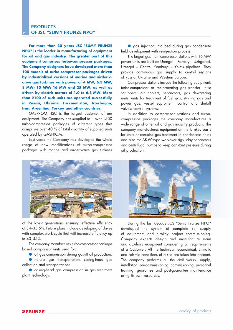
For more than 30 years JSC "SUMY FRUNZENPO" is the leader in manufacturing of equipmentfor oil and gas industry. The greater part of thisequipment comprises turbo-compressor packages.The Company designers have developed more than100 models of turbo-compressor packages drivenby industrialized versions of marine and airderiv-ative gas turbines with power of 4 MW; 6.3 MW;8 MW; 10 MW; 16 MW and 25 MW, as well asdriven by electric motors of 1.0 to 6.3 MW. Morethan 2100 of such units are operated successfullyin Russia, Ukraine, Turkmenistan, Azerbaijan,Iran, Argentina, Turkey and other countries.
GASPROM, JSC is the largest customer of ourequipment. The Company has supplied to it over 1500turbo-compressor packages of different types that comprises over 40 % of total quantity of supplied unitsoperated by GASPROM.
Last years the Company has developed the wholerange of new modifications of turbo-compressor packages with marine and airderivative gas turbines
of the latest generations ensuring effective efficiency of 34ñ35.5%. Future plans include developing of driveswith complex work cycle that will increase efficiency upto 43ñ45%.
The company manufactures turbo-compressor packagebased compressor units used for:
● oil gas compression during gas-lift oil production;● natural gas transportation, casing-head gas
collection and transportation;● casing-head gas compression in gas treatment
plant technology;
● gas injection into bed during gas condensatefield development with re-injection process.
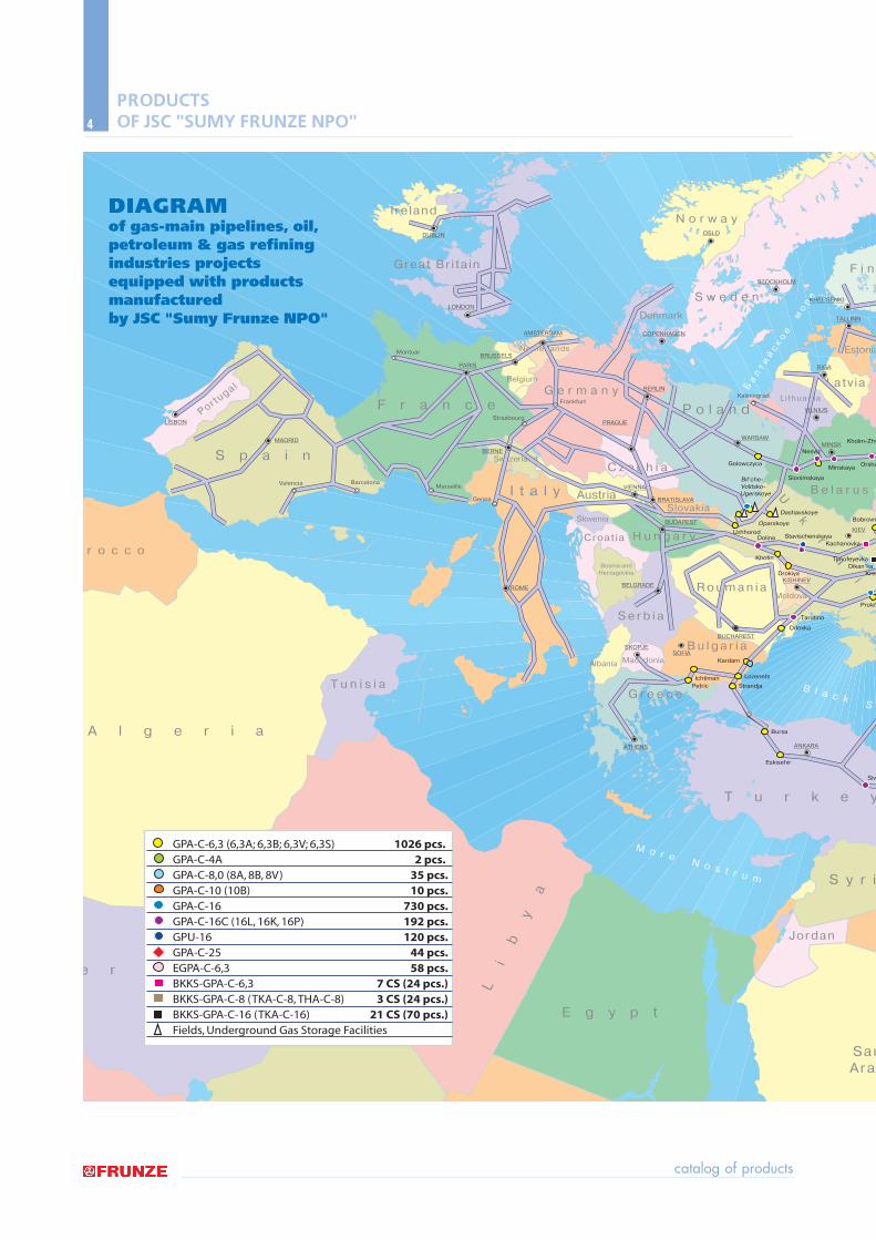
The largest gas main compressor stations with 16 MWpower units are built on Urengoi ñ Pomary ñ Uzhgorod,Urengoi ñ Centre, Yamburg ñ Yelets pipelines. Theyprovide continuous gas supply to central regions of Russia, Ukraine and Western Europe.
Compressor stations include the following equipment:turbo-compressor or reciprocating gas transfer units;scrubbers; air coolers; separators, gas dewateringunits; units for treatment of fuel gas, starting gas andpower gas; vessel equipment, control and shutoffvalves; control systems.
In addition to compressor stations and turbo-compressor packages the company manufactures awide range of other oil and gas industry products. The company manufactures equipment on the turnkey basisfor units of complex gas treatment in condensate fieldsand also for AK-60-type workover rigs, clay separatorsand centrifugal pumps to keep constant pressure duringoil production.
During the last decade JCS "Sumy Frunze NPO"developed the system of complete set supply of equipment and turnkey project commissioning.Company experts design and manufacture main and auxiliary equipment considering all requirements of a Customer. All the technical, economical, climaticand seismic conditions of a site are taken into account.The company performs all the civil works, supply, installation, pre-commissioning, commissioning, personneltraining, guarantee and post-guarantee maintenanceusing its own resources.
catalog of products
2
PRODUCTS OF JSC "SUMY FRUNZE NPO"
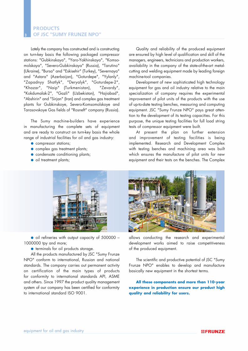
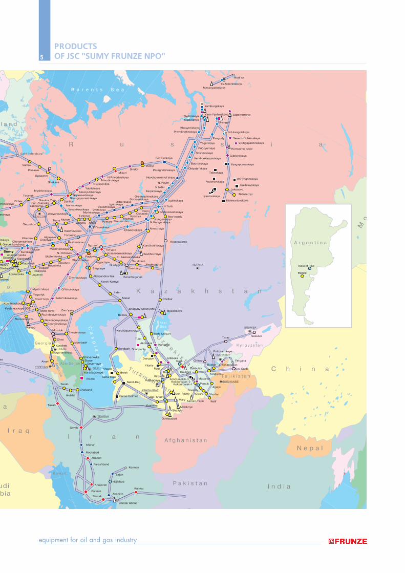
Lately the company has constructed and is constructingon turn-key basis the following packaged compressorstations: "Gubkinskaya", "Yaro-Yakhinskaya", "Komso-molskaya", "Severo-Gubkinskaya" (Russia), "Tarutino"(Ukraine), "Bursa" and "Eskisehir" (Turkey), "Severnaya"and "Astara" (Azerbaijan), "Goturdepe", "Yylanly","Zapadnyy Shatlyk", "Deryalyk", "Goturdepe-2","Khazar", "Naip" (Turkmenistan), "Zevardy","Kokdumalak-2", "Gazli" (Uzbekistan), "Hajiabad","Abshirin" and "Sirjan" (Iran) and complex gas treatmentplants for Gubkinskoye, Severo-Komsomolskoye andTarasovskoye Gas fields of "Rosneft" company (Russia).
The Sumy machine-builders have experience in manufacturing the complete sets of equipment and are ready to construct on turn-key basis the wholerange of industrial facilities for oil and gas industry:
● compressor stations;● complex gas treatment plants;● condensate conditioning plants;● oil treatment plants;
● oil refineries with output capacity of 500000 ñ1000000 tpy and more;
● terminals for oil products storage.All the products manufactured by JSC "Sumy Frunze
NPO" conform to international, Russian and nationalstandards. The company carries out permanent activityon certification of the main types of products for conformity to international standards API, ASMEand others. Since 1997 the product quality managementsystem of our company has been certified for conformityto international standard ISO 9001.
Quality and reliability of the produced equipmentare ensured by high level of qualification and skill of themanagers, engineers, technicians and production workers,availability in the company of the state-of-the-art metal-cutting and welding equipment made by leading foreignmachine-tool companies.
Development of new sophisticated high technologyequipment for gas and oil industry relative to the mainspecialization of company requires the experimentalimprovement of pilot units of the products with the useof up-to-date testing benches, measuring and computingequipment. JSC "Sumy Frunze NPO" pays great atten-tion to the development of its testing capacities. For this purpose, the unique testing facilities for full load stringtests of compressor equipment were built.
At present the plan on further extension and improvement of testing facilities is being implemented. Research and Development Complex with testing benches and machining area was builtwhich ensures the manufacture of pilot units for newequipment and their tests on the benches. The Complex
allows conducting the research and experimental development works aimed to raise competitiveness of the produced equipment.
The scientific and productive potential of JSC "SumyFrunze NPO" enables to develop and manufacture basically new equipment in the shortest terms.
All these components and more than 110-yearexperience in production ensure our product highquality and reliability for users.
equipment for oil and gas industry
3
PRODUCTS OF JSC "SUMY FRUNZE NPO"
catalog of products
4
S p a i n
r o c c o
T u n i s i a
A l g e r i a
Li
by
a
e r
E g y p t
F r a n c e
Netherlands
Denmark
G e r m a n y
P o l a n d
S w e d e n
N o r w a y
F i n
Estonia
LatviaLithuania
B e l a r u s
MoldovaR o u m a n i a
B u l g a r i a
T u r k e y
S y r i
Jordan
SauAra
S e r b i a
Croat ia H u n g a r y
Austria
C z e c h i a
SlovakiaSlovenia
MacedoniaAlbania
G r e e c e
Bosnia andHerzagovina
U
k
r
a
in
Belgium
Switzerland
Great Bri tain
I t a l y
Ireland
Portugal
LISBON
MADRID
PARIS
BRUSSELS
LONDON
AMSTERDAM
BERNE
VIENNA
BRATISLAVA
WARSAWMINSK
VILNIUS
RIGA
BUDAPEST
BELGRADE
SKOPJESOFIA
BUCHAREST
KISHINEV
ATHENS ANKARA
ROME
BERLIN
OSLO
COPENHAGEN
STOCKHOLM
KHEL'SENKI
TALLINN
KIEV
PRAGUE
DUBLIN
Valencia BarcelonaMarseille
Genoa
Strasbourg
Frankfurt
Montuar
Tarutino
Drokiya
Khotin
DolinaUzhhorod
Golowczyca
Slonimskaya
Nesviz
Kaliningrad
MinskayaOrsha
Kholm-Zhy
Bobrovn
Kachanovka
TimofeyevkaDikan’ka
Kres
Prolet
Stavischenskaya
Oparskoye
Dashavskoye
Bil’che- Volitsko- Ugerskoye
Orlovka
Kardam
IchtimanPetric
Lozenets
Strandja B l a c k S
M o r e N o s t r u m
Bursa
Eskisehir
Siva
GPA-C-6,3 (6,3A; 6,3B; 6,3V; 6,3S) 1026 pcs. GPA-C-4A 2 pcs. GPA-C-8,0 (8A, 8B, 8V) 35 pcs.GPA-C-10 (10B) 10 pcs.GPA-C-16 730 pcs.GPA-C-16C (16L, 16K, 16P) 192 pcs.GPU-16 120 pcs.GPA-C-25 44 pcs.EGPA-C-6,3 58 pcs.BKKS-GPA-C-6,3 7 CS (24 pcs.)BKKS-GPA-C-8 (TKA-C-8, THA-C-8) 3 CS (24 pcs.)BKKS-GPA-C-16 (TKA-C-16) 21 CS (70 pcs.)Fields, Underground Gas Storage Facilities
DIAGRAMof gas-main pipelines, oil, petroleum & gas refining industries projects equipped with products manufactured by JSC "Sumy Frunze NPO"
PRODUCTS OF JSC "SUMY FRUNZE NPO"
equipment for oil and gas industry
5
l a n d
a
y
Georgia
a
Kuwait
I r a nA f g h a n i s t a n
K a z a k h s t a n
R u s s i a
Uz
be
ki s
t anT u r k m e n i s t a n
P a k i s t a n I n d i a
N e p a l
T a j i k i s t a n
K y r g y z s t a n
C h i n a
Mo
n
udibia
I r a q
AzerbaijanArm
en
ia
n
e
TEHRAN
ASHGHABAT
BAKU
BISHKEK
TASHKENT
ASTANA
TBILISI
YEREVAN
DUSHANBE
MOSCOW
Saveh
Bastak
Kahnuj
Bandar Abbas
Abadeh
Isfahan
Noorabad
FarashbandKerman
Sirjan
Hajiabad
Abshirin
Khavaran
Parsian
Takab
Ardabil
Sarab
Chalvand
Astara
Belek
Khazar
Pustynnaya
KirpichliGoturdepe
Barsa-Gelmes
Kaakhka
Dovletabad
Shatlyk
Karshi
Kelif
Taraz Sokuluk
Sokuluk
Sokuluk
Chinaz
BukharaZirabulak
Yangiyer
Poltoraczkoye
Fergana
AkhangaranBuston
Sev.Sokh
Shurtan
Agalyk
Mubarek
PamukKokdumalak-2
Kokdumalak-3
Kokdumalak-1
Zevardy
Maiskoye
Uch-Adzhy
Saman-TepeMaryZap. Shatlyk
Nebit-Dag
Severnaya
Shirvanovka
IzberbashKvesheti
Chmi
Mozdok
Zam’yany
Maikop
Izobil’noye
Privol’noye
Berezanskaya
Kushhevskaya
Kushhevskoye UGS
Chervlennaya
GeorgievskayaNevinnomysskaya
Kotel’nikovskaya
Rozhdestvenskaya
Airum
Saguramskaya
Siazan
Karadagskoye
anskaya
yrkovskayaRzhev
Torzhok
Serpuhov
EfremovCheremisinovo
Grebenkovskaya
itskaya
stishhiShebelinka
Loskutovka
Kigichevka
Kupyansk
KurskayaDolgoe
LuganskPisarevka
KapachBubnovka
Balashov
Oktyabr’skaya
Yegorlyk
Ol’khovskaya
Zhyrnovskaya
Krasnoarmeiskaya
StorozhovkaPavlovka
PugachyovBurdygino
Stepnoye
Karachaganak
Inder
Makat
Beineu
Bekdash Shahpahty
Deryalyk
YilanlyNaip
Kungrad
EllikkalaGazli
Tulei
Akchalok
Yuzh. Ustyurt
Chelkar
Bezaiskoye
AralSea
Karakalpakskaya
Shagyrly-Shomyshty
Orenburg
Saraktash
Almaznaya
Nev’yansk
Mednogorsk
Sovkhoznoye
KonchurinskayaKrasnogorsk
Aleksandrov Gai
Kysyk-Kamys
St. Aleksandrovka
Syzran’
Tol’yatti
EkaterinovkaN. Petrovsk
Meshherskaya
BashmakovoChaplygin
Algasovo
Kasimovskoe
Tuma MuromVorsma
Lukoyanovskaya
YakhromaPer. Zalesskii
Gavrilov Yam
Myshkinskaya
Saint Petersburg
Sheksna
Babayevo
Pikalevo
Volhov
Danilov
Ivanovskaya
NovogryazovetskayaGryazovetskaya
Yubileinaya
Mikun’
VuktylSindor
Novoyubileinaya
N.Privodinskaya
Sos’vinskaya
PrivodinskayaNyuksenitsa
Lyskovo
VyaznikovskayaMorkinskaya
Vyatskaya
Ishlei
Pil’nenskaya
Pomary ShemordanMozhga
Chaikovskaya
Votkinsk
Dobryanskaya
Karpinskaya
Bobrovskaya
Sosnovskaya
Khasyreiskaya
NydinskayaMedvezhye
Zapolyarnoye
Messoyakhskoye
Yu.Soleninskoye
Yagel’naya
Priozyornaya
Yamburgskaya
Noril’sk
Pangody
Oktyabr’skaya
Lyalinskaya
LyantovskayaBelozernyi
Lokosovo
Fedorovskaya
Talinskaya
Vyngapurovskaya
Gubkinskaya
N.Urengoiskaya
Urengoi
Vykhgayakhinskaya
Komsomol’skoe
Nijnevartovskaya
Bakhilovskaya
Var’yeganskaya
Gremyachinskaya
Peregrebinskaya
Verkhnekazymskaya
Pravokhetinskaya
Novokomsomol’skaya
Gornozavodskaya
KungurskayaN.Kungurskaya
OkhanskPerm
N.Tura
N.Ivdel
N.Pelym
VavozhskayaIgrinskaya
Ocherskaya
Torbeevo
tarskoe
SolokhaAnastas’yevka
Sumy
e a
B a r e n t s S e a
Ca
sp
ia
n
Se
a
as
Yaro-Yakhinskaya
Severo-Gubkinskaya
Belisle
Indio of Riko
A r g e n t i n a
PRODUCTS OF JSC "SUMY FRUNZE NPO"
catalog of products
6
MODULAR COMPRESSOR STATIONS WITH CENTRIFUGAL COMPRESSORS
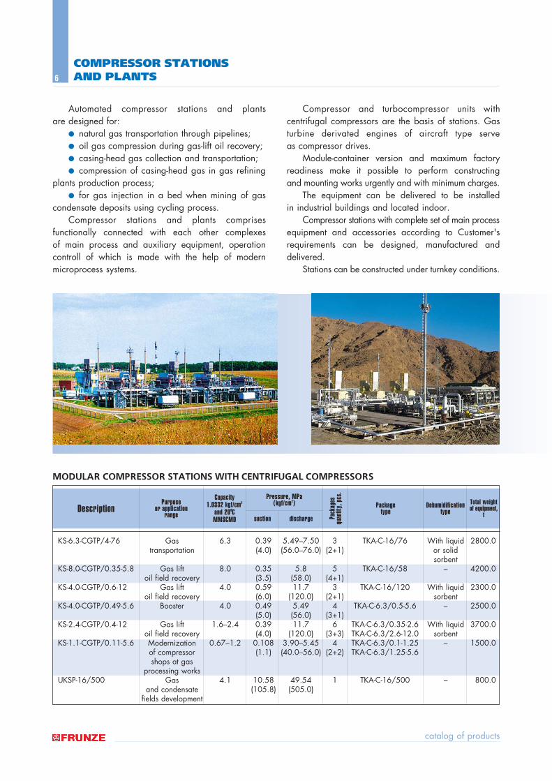
Automated compressor stations and plants are designed for:
● natural gas transportation through pipelines;● oil gas compression during gas-lift oil recovery;● casing-head gas collection and transportation; ● compression of casing-head gas in gas refining
plants production process; ● for gas injection in a bed when mining of gas
condensate deposits using cycling process. Compressor stations and plants comprises
functionally connected with each other complexes of main process and auxiliary equipment, operationcontroll of which is made with the help of modern microprocess systems.
Compressor and turbocompressor units with centrifugal compressors are the basis of stations. Gasturbine derivated engines of aircraft type serve as compressor drives.
Module-container version and maximum factoryreadiness make it possible to perform constructing and mounting works urgently and with minimum charges.
The equipment can be delivered to be installed in industrial buildings and located indoor.
Compressor stations with complete set of main processequipment and accessories according to Customer'srequirements can be designed, manufactured and delivered.
Stations can be constructed under turnkey conditions.
COMPRESSOR STATIONS AND PLANTS
KS-6.3-CGTP/4-76 Gas 6.3 0.39 5.49ñ7.50 3 TKA-C-16/76 With liquid 2800.0transportation (4.0) (56.0ñ76.0) (2+1) or solid
sorbentKS-8.0-CGTP/0.35-5.8 Gas lift 8.0 0.35 5.8 5 TKA-C-16/58 ñ 4200.0
oil field recovery (3.5) (58.0) (4+1)KS-4.0-CGTP/0.6-12 Gas lift 4.0 0.59 11.7 3 TKA-C-16/120 With liquid 2300.0
oil field recovery (6.0) (120.0) (2+1) sorbentKS-4.0-CGTP/0.49-5.6 Booster 4.0 0.49 5.49 4 TKA-C-6.3/0.5-5.6 ñ 2500.0
(5.0) (56.0) (3+1)KS-2.4-CGTP/0.4-12 Gas lift 1.6ñ2.4 0.39 11.7 6 TKA-C-6.3/0.35-2.6 With liquid 3700.0
oil field recovery (4.0) (120.0) (3+3) TKA-C-6.3/2.6-12.0 sorbentKS-1.1-CGTP/0.11-5.6 Modernization 0.67ñ1.2 0.108 3.90ñ5.45 4 TKA-C-6.3/0.1-1.25 ñ 1500.0
of compressor (1.1) (40.0ñ56.0) (2+2) TKA-C-6.3/1.25-5.6shops at gas
processing worksUKSP-16/500 Gas 4.1 10.58 49.54 1 TKA-C-16/500 ñ 800.0
and condensate (105.8) (505.0)fields development
DescriptionPurpose
or application range
Capacity 1.0332 kgf/cm2
and 200C MMSCMD
Package type
Dehumidificationtype
Total weightof equipment,
t
Pressure, MPa (kgf/cm2)
Pack
ages
qu
antit
y, p
cs.
suction discharge
equipment for oil and gas industry
7
MODULAR COMPRESSOR STATIONS WITH CENTRIFUGAL COMPRESSORS
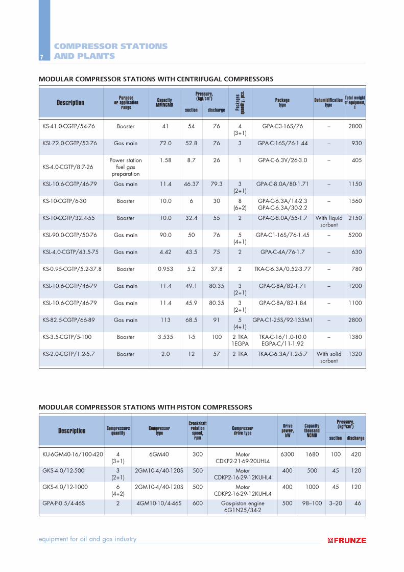
MODULAR COMPRESSOR STATIONS WITH PISTON COMPRESSORS
COMPRESSOR STATIONS AND PLANTS
KU-6GM40-16/100-420 4 6GM40 300 Motor 6300 1680 100 420(3+1) CDKP2-21-69-20UHL4
GKS-4.0/12-500 3 2GM10-4/40-120S 500 Motor 400 500 45 120(2+1) CDKP2-16-29-12KUHL4
GKS-4.0/12-1000 6 2GM10-4/40-120S 500 Motor 400 1000 45 120(4+2) CDKP2-16-29-12KUHL4
GPA-P-0.5/4-46S 2 4GM10-10/4-46S 600 Gas-piston engine 500 98ñ100 3ñ20 466G1N25/34-2
Description Compressorsquantity
Compressor type
Crankshaftrotationspeed,
rpm
Drivepower,
kWCompressor drive type
Capacity thousand
NCMD
Pressure, (kgf/cm2)
suction discharge
KS-41.0-CGTP/54-76 Booster 41 54 76 4 GPA-C3-16S/76 ñ 2800(3+1)
KSL-72.0-CGTP/53-76 Gas main 72.0 52.8 76 3 GPA-C-16S/76-1.44 ñ 930
Power station 1.58 8.7 26 1 GPA-C-6.3V/26-3.0 ñ 405KS-4.0-CGTP/8.7-26 fuel gas
preparation
KSL-10.6-CGTP/46-79 Gas main 11.4 46.37 79.3 3 GPA-C-8.0A/80-1.71 ñ 1150(2+1)
KS-10-CGTP/6-30 Booster 10.0 6 30 8 GPA-C-6.3A/14-2.3 ñ 1560(6+2) GPA-C-6.3A/30-2.2
KS-10-CGTP/32.4-55 Booster 10.0 32.4 55 2 GPA-C-8.0A/55-1.7 With liquid 2150sorbent
KSL-90.0-CGTP/50-76 Gas main 90.0 50 76 5 GPA-C1-16S/76-1.45 ñ 5200(4+1)
KSL-4.0-CGTP/43.5-75 Gas main 4.42 43.5 75 2 GPA-C-4A/76-1.7 ñ 630
KS-0.95-CGTP/5.2-37.8 Booster 0.953 5.2 37.8 2 TKA-C-6.3A/0.52-3.77 ñ 780
KSL-10.6-CGTP/46-79 Gas main 11.4 49.1 80.35 3 GPA-C-8A/82-1.71 ñ 1200(2+1)
KSL-10.6-CGTP/46-79 Gas main 11.4 45.9 80.35 3 GPA-C-8A/82-1.84 ñ 1100(2+1)
KS-82.5-CGTP/66-89 Gas main 113 68.5 91 5 GPA-C1-25S/92-135M1 ñ 2800(4+1)
KS-3.5-CGTP/5-100 Booster 3.535 1-5 100 2 TKA TKA-C-16/1.0-10.0 ñ 13801EGPA EGPA-C/11-1.92
KS-2.0-CGTP/1.2-5.7 Booster 2.0 12 57 2 TKA TKA-C-6.3A/1.2-5.7 With solid 1320sorbent
DescriptionPurpose
or application range
CapacityMMNCMD
Package type
Dehumidificationtype
Total weightof equipment,
t
Pressure,(kgf/cm2)
Pack
ages
qu
antit
y, p
cs.
suction discharge
catalog of products
8
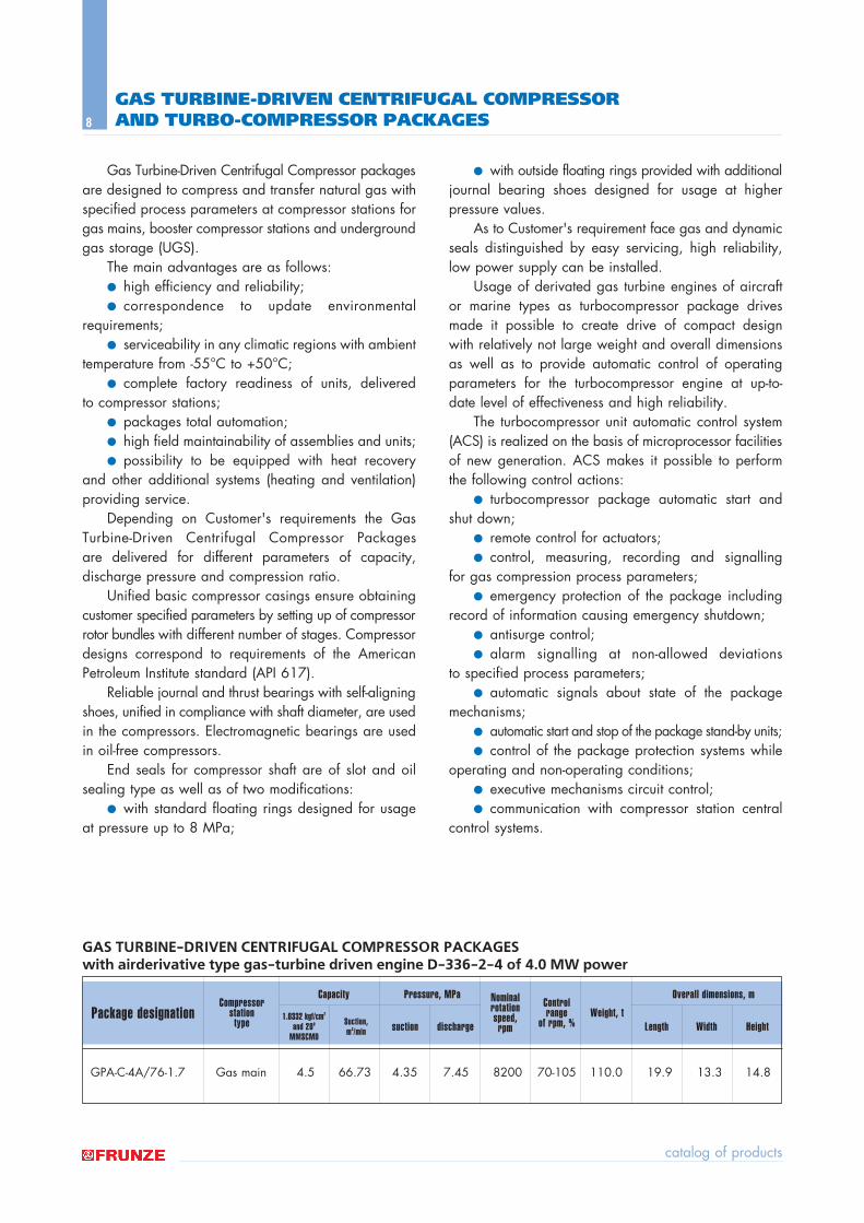
GAS TURBINE-DRIVEN CENTRIFUGAL COMPRESSOR PACKAGES with airderivative type gas-turbine driven engine D-336-2-4 of 4.0 MW power
GAS TURBINE-DRIVEN CENTRIFUGAL COMPRESSOR AND TURBO-COMPRESSOR PACKAGES
Gas Turbine-Driven Centrifugal Compressor packagesare designed to compress and transfer natural gas withspecified process parameters at compressor stations forgas mains, booster compressor stations and undergroundgas storage (UGS).
The main advantages are as follows: ● high efficiency and reliability; ● correspondence to update environmental
requirements;● serviceability in any climatic regions with ambient
temperature from -55∞C to +50∞C;● complete factory readiness of units, delivered
to compressor stations;● packages total automation;● high field maintainability of assemblies and units;● possibility to be equipped with heat recovery
and other additional systems (heating and ventilation)providing service.
Depending on Customer's requirements the GasTurbine-Driven Centrifugal Compressor Packages are delivered for different parameters of capacity, discharge pressure and compression ratio.
Unified basic compressor casings ensure obtainingcustomer specified parameters by setting up of compressorrotor bundles with different number of stages. Compressordesigns correspond to requirements of the AmericanPetroleum Institute standard (API 617).
Reliable journal and thrust bearings with self-aligningshoes, unified in compliance with shaft diameter, are usedin the compressors. Electromagnetic bearings are usedin oil-free compressors.
End seals for compressor shaft are of slot and oilsealing type as well as of two modifications:
● with standard floating rings designed for usageat pressure up to 8 MPa;
● with outside floating rings provided with additionaljournal bearing shoes designed for usage at higherpressure values.
As to Customer's requirement face gas and dynamicseals distinguished by easy servicing, high reliability,low power supply can be installed.
Usage of derivated gas turbine engines of aircraftor marine types as turbocompressor package drivesmade it possible to create drive of compact design with relatively not large weight and overall dimensionsas well as to provide automatic control of operatingparameters for the turbocompressor engine at up-to-date level of effectiveness and high reliability.
The turbocompressor unit automatic control system(ACS) is realized on the basis of microprocessor facilitiesof new generation. ACS makes it possible to performthe following control actions:
● turbocompressor package automatic start andshut down;
● remote control for actuators; ● control, measuring, recording and signalling
for gas compression process parameters; ● emergency protection of the package including
record of information causing emergency shutdown; ● antisurge control; ● alarm signalling at non-allowed deviations
to specified process parameters; ● automatic signals about state of the package
mechanisms; ● automatic start and stop of the package stand-by units;● control of the package protection systems while
operating and non-operating conditions; ● executive mechanisms circuit control; ● communication with compressor station central
control systems.
GPA-C-4A/76-1.7 Gas main 4.5 66.73 4.35 7.45 8200 70-105 110.0 19.9 13.3 14.8
Package designationCompressor
station type
Weight, tNominalrotationspeed,
rpm
Control range
of rpm, %
Overall dimensions, mCapacity
1.0332 kgf/cm2
and 200
MMSCMD
Suction, m3/min
Pressure, MPa
suction discharge Length Width Height
equipment for oil and gas industry
9
GAS TURBINE-DRIVEN CENTRIFUGAL COMPRESSOR AND TURBO-COMPRESSOR PACKAGES
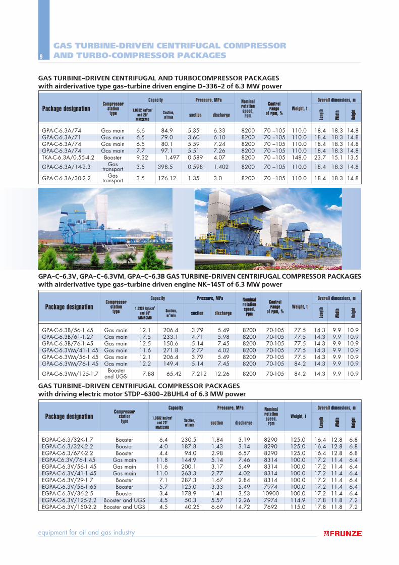
GAS TURBINE-DRIVEN CENTRIFUGAL AND TURBOCOMPRESSOR PACKAGES with airderivative type gas-turbine driven engine D-336-2 of 6.3 MW power
GPA-C-6.3V, GPA-C-6.3VM, GPA-C-6.3B GAS TURBINE-DRIVEN CENTRIFUGAL COMPRESSOR PACKAGESwith airderivative type gas-turbine driven engine NK-14ST of 6.3 MW power
GPA-C-6.3B/56-1.45 Gas main 12.1 206.4 3.79 5.49 8200 70-105 77.5 14.3 9.9 10.9GPA-C-6.3B/61-1.27 Gas main 17.5 233.1 4.71 5.98 8200 70-105 77.5 14.3 9.9 10.9GPA-C-6.3B/76-1.45 Gas main 12.5 150.6 5.14 7.45 8200 70-105 77.5 14.3 9.9 10.9GPA-C-6.3VM/41-1.45 Gas main 11.6 271.8 2.77 4.02 8200 70-105 77.5 14.3 9.9 10.9GPA-C-6.3VM/56-1.45 Gas main 12.1 206.4 3.79 5.49 8200 70-105 77.5 14.3 9.9 10.9GPA-C-6.3VM/76-1.45 Gas main 12.2 149.4 5.14 7.45 8200 70-105 84.2 14.3 9.9 10.9
GPA-C-6.3VM/125-1.7 Booster 7.88 65.42 7.212 12.26 8200 70-105 84.2 14.3 9.9 10.9and UGS
Package designationCompressor
station type
Weight, tNominal rotation speed,
rpm Leng
th
Wid
th
Heig
ht
Control range
of rpm, %
Overall dimensions, mCapacity
1.0332 kgf/cm2
and 200
MMSCMD
Suction, m3/min
Pressure, MPa
suction discharge
GAS TURBINE-DRIVEN CENTRIFUGAL COMPRESSOR PACKAGES with driving electric motor STDP-6300-2BUHL4 of 6.3 MW power
EGPA-C-6.3/32K-1.7 Booster 6.4 230.5 1.84 3.19 8290 125.0 16.4 12.8 6.8EGPA-C-6.3/32K-2.2 Booster 4.0 187.8 1.43 3.14 8290 125.0 16.4 12.8 6.8EGPA-C-6.3/67K-2.2 Booster 4.4 94.0 2.98 6.57 8290 125.0 16.4 12.8 6.8EGPA-C6.3V/76-1.45 Gas main 11.8 144.9 5.14 7.46 8314 100.0 17.2 11.4 6.4EGPA-C-6.3V/56-1.45 Gas main 11.6 200.1 3.17 5.49 8314 100.0 17.2 11.4 6.4EGPA-C-6.3V/41-1.45 Gas main 11.0 263.3 2.77 4.02 8314 100.0 17.2 11.4 6.4EGPA-C-6.3V/29-1.7 Booster 7.1 287.3 1.67 2.84 8314 100.0 17.2 11.4 6.4EGPA-C-6.3V/56-1.65 Booster 5.7 125.0 3.33 5.49 7974 100.0 17.2 11.4 6.4EGPA-C-6.3V/36-2.5 Booster 3.4 178.9 1.41 3.53 10900 100.0 17.2 11.4 6.4EGPA-C-6.3V/125-2.2 Booster and UGS 4.5 50.3 5.57 12.26 7974 114.9 17.8 11.8 7.2EGPA-C-6.3V/150-2.2 Booster and UGS 4.5 40.25 6.69 14.72 7692 115.0 17.8 11.8 7.2
Package designationCompressor
station type
Weight, tNominal rotation speed,
rpm Leng
th
Wid
th
Heig
ht
Overall dimensions, mCapacity
1.0332 kgf/cm2
and 200
MMSCMD
Suction, m3/min
Pressure, MPa
suction discharge
GPA-C-6.3¿/74 Gas main 6.6 84.9 5.35 6.33 8200 70 ñ105 110.0 18.4 18.3 14.8GPA-C-6.3¿/71 Gas main 6.5 79.0 3.60 6.10 8200 70 ñ105 110.0 18.4 18.3 14.8GPA-C-6.3¿/74 Gas main 6.5 80.1 5.59 7.24 8200 70 ñ105 110.0 18.4 18.3 14.8GPA-C-6.3¿/74 Gas main 7.7 97.1 5.51 7.26 8200 70 ñ105 110.0 18.4 18.3 14.8TKA-C-6.3¿/0.55-4.2 Booster 9.32 1.497 0.589 4.07 8200 70 ñ105 148.0 23.7 15.1 13.5
GPA-C-6.3¿/14-2.3 Gas 3.5 398.5 0.598 1.402 8200 70 ñ105 110.0 18.4 18.3 14.8transport
GPA-C-6.3¿/30-2.2 Gas 3.5 176.12 1.35 3.0 8200 70 ñ105 110.0 18.4 18.3 14.8transport
Package designationCompressor
station type
Weight, tNominal rotationspeed,
rpm Leng
th
Wid
th
Heig
ht
Control range
of rpm, %
Overall dimensions, mCapacity
1.0332 kgf/cm2
and 200
MMSCMD
Suction, m3/min
Pressure, MPa
suction discharge
catalog of products
10
GAS TURBINE-DRIVEN CENTRIFUGAL COMPRESSOR AND TURBO-COMPRESSOR PACKAGES
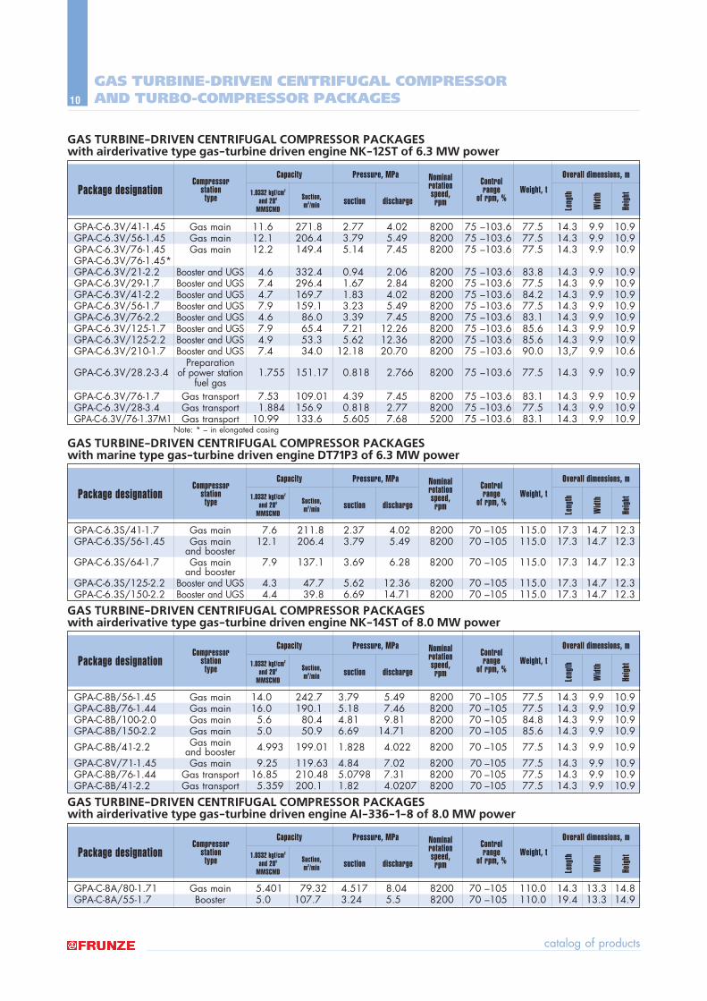
GAS TURBINE-DRIVEN CENTRIFUGAL COMPRESSOR PACKAGES with airderivative type gas-turbine driven engine NK-12ST of 6.3 MW power
GPA-C-6.3V/41-1.45 Gas main 11.6 271.8 2.77 4.02 8200 75 ñ103.6 77.5 14.3 9.9 10.9GPA-C-6.3V/56-1.45 Gas main 12.1 206.4 3.79 5.49 8200 75 ñ103.6 77.5 14.3 9.9 10.9GPA-C-6.3V/76-1.45 Gas main 12.2 149.4 5.14 7.45 8200 75 ñ103.6 77.5 14.3 9.9 10.9GPA-C-6.3V/76-1.45*GPA-C-6.3V/21-2.2 Booster and UGS 4.6 332.4 0.94 2.06 8200 75 ñ103.6 83.8 14.3 9.9 10.9GPA-C-6.3V/29-1.7 Booster and UGS 7.4 296.4 1.67 2.84 8200 75 ñ103.6 77.5 14.3 9.9 10.9GPA-C-6.3V/41-2.2 Booster and UGS 4.7 169.7 1.83 4.02 8200 75 ñ103.6 84.2 14.3 9.9 10.9GPA-C-6.3V/56-1.7 Booster and UGS 7.9 159.1 3.23 5.49 8200 75 ñ103.6 77.5 14.3 9.9 10.9GPA-C-6.3V/76-2.2 Booster and UGS 4.6 86.0 3.39 7.45 8200 75 ñ103.6 83.1 14.3 9.9 10.9GPA-C-6.3V/125-1.7 Booster and UGS 7.9 65.4 7.21 12.26 8200 75 ñ103.6 85.6 14.3 9.9 10.9GPA-C-6.3V/125-2.2 Booster and UGS 4.9 53.3 5.62 12.36 8200 75 ñ103.6 85.6 14.3 9.9 10.9GPA-C-6.3V/210-1.7 Booster and UGS 7.4 34.0 12.18 20.70 8200 75 ñ103.6 90.0 13,7 9.9 10.6
PreparationGPA-C-6.3V/28.2-3.4 of power station 1.755 151.17 0.818 2.766 8200 75 ñ103.6 77.5 14.3 9.9 10.9
fuel gasGPA-C-6.3V/76-1.7 Gas transport 7.53 109.01 4.39 7.45 8200 75 ñ103.6 83.1 14.3 9.9 10.9GPA-C-6.3V/28-3.4 Gas transport 1.884 156.9 0.818 2.77 8200 75 ñ103.6 77.5 14.3 9.9 10.9GPA-C-6.3V/76-1.37M1 Gas transport 10.99 133.6 5.605 7.68 5200 75 ñ103.6 83.1 14.3 9.9 10.9
Note: * ñ in elongated casing
GAS TURBINE-DRIVEN CENTRIFUGAL COMPRESSOR PACKAGES with marine type gas-turbine driven engine DT71P3 of 6.3 MW power
GPA-C-6.3S/41-1.7 Gas main 7.6 211.8 2.37 4.02 8200 70 ñ105 115.0 17.3 14.7 12.3GPA-C-6.3S/56-1.45 Gas main 12.1 206.4 3.79 5.49 8200 70 ñ105 115.0 17.3 14.7 12.3
and boosterGPA-C-6.3S/64-1.7 Gas main 7.9 137.1 3.69 6.28 8200 70 ñ105 115.0 17.3 14.7 12.3
and boosterGPA-C-6.3S/125-2.2 Booster and UGS 4.3 47.7 5.62 12.36 8200 70 ñ105 115.0 17.3 14.7 12.3GPA-C-6.3S/150-2.2 Booster and UGS 4.4 39.8 6.69 14.71 8200 70 ñ105 115.0 17.3 14.7 12.3
GAS TURBINE-DRIVEN CENTRIFUGAL COMPRESSOR PACKAGES with airderivative type gas-turbine driven engine NK-14ST of 8.0 MW power
GPA-C-8B/56-1.45 Gas main 14.0 242.7 3.79 5.49 8200 70 ñ105 77.5 14.3 9.9 10.9GPA-C-8B/76-1.44 Gas main 16.0 190.1 5.18 7.46 8200 70 ñ105 77.5 14.3 9.9 10.9GPA-C-8B/100-2.0 Gas main 5.6 80.4 4.81 9.81 8200 70 ñ105 84.8 14.3 9.9 10.9GPA-C-8B/150-2.2 Gas main 5.0 50.9 6.69 14.71 8200 70 ñ105 85.6 14.3 9.9 10.9
GPA-C-8B/41-2.2 Gas main 4.993 199.01 1.828 4.022 8200 70 ñ105 77.5 14.3 9.9 10.9and boosterGPA-C-8V/71-1.45 Gas main 9.25 119.63 4.84 7.02 8200 70 ñ105 77.5 14.3 9.9 10.9GPA-C-8B/76-1.44 Gas transport 16.85 210.48 5.0798 7.31 8200 70 ñ105 77.5 14.3 9.9 10.9GPA-C-8B/41-2.2 Gas transport 5.359 200.1 1.82 4.0207 8200 70 ñ105 77.5 14.3 9.9 10.9
GAS TURBINE-DRIVEN CENTRIFUGAL COMPRESSOR PACKAGES with airderivative type gas-turbine driven engine AI-336-1-8 of 8.0 MW power
GPA-C-8¿/80-1.71 Gas main 5.401 79.32 4.517 8.04 8200 70 ñ105 110.0 14.3 13.3 14.8GPA-C-8¿/55-1.7 Booster 5.0 107.7 3.24 5.5 8200 70 ñ105 110.0 19.4 13.3 14.9
Package designationCompressor
station type
Weight, tNominalrotationspeed,
rpm
Leng
th
Wid
th
Heig
ht
Control range
of rpm, %
Overall dimensions, mCapacity
1.0332 kgf/cm2
and 200
MMSCMD
Suction, m3/min
Pressure, MPa
suction discharge
Package designationCompressor
station type
Weight, tNominalrotationspeed,
rpm
Leng
th
Wid
th
Heig
ht
Control range
of rpm, %
Overall dimensions, mCapacity
1.0332 kgf/cm2
and 200
MMSCMD
Suction, m3/min
Pressure, MPa
suction discharge
Package designationCompressor
station type
Weight, tNominalrotationspeed,
rpm
Leng
th
Wid
th
Heig
ht
Control range
of rpm, %
Overall dimensions, mCapacity
1.0332 kgf/cm2
and 200
MMSCMD
Suction, m3/min
Pressure, MPa
suction discharge
Package designationCompressor
station type
Weight, tNominalrotationspeed,
rpm
Leng
th
Wid
th
Heig
ht
Control range
of rpm, %
Overall dimensions, mCapacity
1.0332 kgf/cm2
and 200
MMSCMD
Suction, m3/min
Pressure, MPa
suction discharge
equipment for oil and gas industry
11
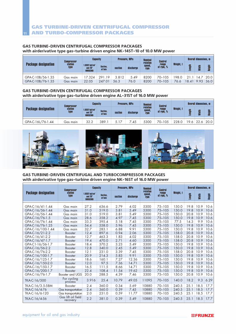
GAS TURBINE-DRIVEN CENTRIFUGAL AND TURBOCOMPRESSOR PACKAGES with airderivative type gas-turbine driven engine NK-16ST of 16.0 MW power
GPA-C-16/41-1.44 Gas main 27.2 636.6 2.79 4.02 5300 75ñ105 150.0 19.8 10.9 10.6GPA-C-16/56-1.44 Gas main 31.0 519.0 3.81 5.49 5300 75ñ105 150.0 19.8 10.9 10.6GPA-C-16/56-1.44 Gas main 31.0 519.0 3.81 5.49 5300 75ñ105 150.0 20.8 10.9 10.6GPA-C-16/76-1.5 Gas main 28.6 358.2 4.97 7.45 5300 75ñ105 150.0 19.8 10.9 10.6GPA-C-16/76-1.44 Gas main 33.3 395.4 5.18 7.45 5300 75ñ105 77.5 14.3 9.9 10.6GPA-C-16/76-1.25 Gas main 54.4 558.0 5.96 7.45 5300 75ñ105 150.0 19.8 10.9 10.6GPA-C-16/100-1.44 Gas main 32.7 283.1 6.88 9.91 5300 75ñ105 150.0 19.8 10.9 10.6GPA-C-16/21-2.2 Booster 12.4 897.6 0.94 2.06 5300 75ñ105 158.0 20.8 10.9 10.6GPA-C-16/41-2.2 Booster 12.7 463.3 1.83 4.02 5300 75ñ105 158.0 20.8 10.9 10.6GPA-C-16/47-1.7 Booster 19.4 470.0 2.71 4.60 5300 75ñ105 158.0 20.8 10.9 10.6GPA-C1-16/56-1.7 Booster 18.4 370.2 3.23 5.49 5300 75ñ105 150.0 19.8 10.9 10.6GPA-C-16/56-2.2 Booster 12.8 340.0 2.45 5.49 5300 75ñ105 150.0 19.8 10.9 10.6GPA-C-16/76-2.2 Booster 12.1 231.0 3.39 7.45 5300 75ñ105 158.0 20.8 10.9 10.6GPA-C-16/100-1.7 Booster 20.9 214.3 5.83 9.91 5300 75ñ105 150.0 19.8 10.9 10.6GPA-C-16/125-1.7 Booster 18.6 160.1 7.27 12.36 5300 75ñ105 150.0 19.8 10.9 10.6GPA-C-16/150-2.0 Booster 12.0 97.5 7.36 14.71 5300 75ñ105 150.0 19.8 10.9 10.6GPA-C-16/150-1.7 Booster 16.5 111.5 8.66 14.71 5300 75ñ105 150.0 19.8 10.9 10.6GPA-C-16/200-1.7 Booster 22.4 108.4 11.54 19.62 5300 75ñ105 150.0 19.8 10.9 10.6GPA-C-16/76-1.7 Booster and UGS 20.0 288.5 4.39 7.46 5300 75ñ105 150.0 20.8 10.9 10.6
For cycling 3.916 25.4 10.79 49.05 11095 70ñ105 140.0 18.2 9.3 6.29TKA-C-16/500 processTKA-C-16/3.5-58M Booster 2.4 360.0 0.34 5.69 10880 70ñ105 240.5 25.1 18.5 17.7TKA-C-16/4-76 Gas transportation 2.4 360.0 0.39 7.45 10880 70ñ105 240.5 25.1 18.5 17.7TKA-C-16/6-120 Gas transportation 2.0 231.0 0.59 11.77 10880 70ñ105 240.5 25.1 18.5 17.7
TKA-C-16/4-56 Gas lift oil field 2.2 381.0 0.39 5.49 10880 70ñ105 240.5 25.1 18.5 17.7recovery
Package designationCompressor
station type
Weight, tNominalrotationspeed,
rpm Leng
th
Wid
th
Heig
ht
Control range
of rpm, %
Overall dimensions, mCapacity
1.0332 kgf/cm2
and 200
MMSCMD
Suction, m3/min
Pressure, MPa
suction discharge
GAS TURBINE-DRIVEN CENTRIFUGAL COMPRESSOR PACKAGES with airderivative type gas-turbine driven engine NK-14ST-10 of 10.0 MW power
GPA-C-10B/56-1.35 Gas main 17.324 291.19 3.812 5.49 8200 70ñ105 198.0 21.1 14.7 20.0GPA-C-10B/76-1.35 Gas main 22.05 247.01 56.3 76.0 8200 70ñ105 76.6 18.41 9.93 36.0
Package designationCompressor
station type
Weight, tNominalrotationspeed,
rpm Leng
th
Wid
th
Heig
ht
Control range
of rpm, %
Overall dimensions, mCapacity
1.0332 kgf/cm2
and 200
MMSCMD
Suction, m3/min
Pressure, MPa
suction discharge
GAS TURBINE-DRIVEN CENTRIFUGAL COMPRESSOR PACKAGES with airderivative type gas-turbine driven engine AL-31ST of 16.0 MW power
GPA-C-16L/76-1.44 Gas main 32.2 389.1 5.17 7.45 5300 70ñ105 228.0 19.6 22.6 20.0
Package designationCompressor
station type
Weight, tNominalrotationspeed,
rpm Leng
th
Wid
th
Heig
ht
Control range
of rpm, %
Overall dimensions, mCapacity
1.0332 kgf/cm2
and 200
MMSCMD
Suction, m3/min
Pressure, MPa
suction discharge
GAS TURBINE-DRIVEN CENTRIFUGAL COMPRESSOR AND TURBO-COMPRESSOR PACKAGES
catalog of products
12
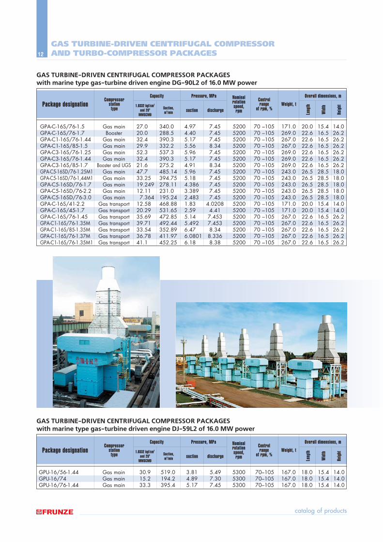
GAS TURBINE-DRIVEN CENTRIFUGAL COMPRESSOR PACKAGES with marine type gas-turbine driven engine DJ-59L2 of 16.0 MW power
GPU-16/56-1.44 Gas main 30.9 519.0 3.81 5.49 5300 70ñ105 167.0 18.0 15.4 14.0GPU-16/74 Gas main 15.2 194.2 4.89 7.30 5300 70ñ105 167.0 18.0 15.4 14.0GPU-16/76-1.44 Gas main 33.3 395.4 5.17 7.45 5300 70ñ105 167.0 18.0 15.4 14.0
Package designationCompressor
station type
Weight, tNominalrotationspeed,
rpm Leng
th
Wid
th
Heig
ht
Control range
of rpm, %
Overall dimensions, mCapacity
1.0332 kgf/cm2
and 200
MMSCMD
Suction, m3/min
Pressure, MPa
suction discharge
GAS TURBINE-DRIVEN CENTRIFUGAL COMPRESSOR AND TURBO-COMPRESSOR PACKAGES
GAS TURBINE-DRIVEN CENTRIFUGAL COMPRESSOR PACKAGES with marine type gas-turbine driven engine DG-90L2 of 16.0 MW power
GPA-C-16S/76-1.5 Gas main 27.0 340.0 4.97 7.45 5200 70 ñ105 171.0 20.0 15.4 14.0GPA-C-16S/76-1.7 Booster 20.0 288.5 4.40 7.45 5200 70 ñ105 269.0 22.6 16.5 26.2GPA-C1-16S/76-1.44 Gas main 32.4 390.3 5.17 7.45 5200 70 ñ105 267.0 22.6 16.5 26.2GPA-C1-16S/85-1.5 Gas main 29.9 332.2 5.56 8.34 5200 70 ñ105 267.0 22.6 16.5 26.2GPA-C3-16S/76-1.25 Gas main 52.3 537.3 5.96 7.45 5200 70 ñ105 269.0 22.6 16.5 26.2GPA-C3-16S/76-1.44 Gas main 32.4 390.3 5.17 7.45 5200 70 ñ105 269.0 22.6 16.5 26.2GPA-C3-16S/85-1.7 Booster and UGS 21.6 275.2 4.91 8.34 5200 70 ñ105 269.0 22.6 16.5 26.2GPA-C5-16SD/76-1.25Ã1 Gas main 47.7 485.14 5.96 7.45 5200 70 ñ105 243.0 26.5 28.5 18.0GPA-C5-16SD/76-1,44Ã1 Gas main 33.25 394.75 5.18 7.45 5200 70 ñ105 243.0 26.5 28.5 18.0GPA-C5-16SD/76-1.7 Gas main 19.249 278.11 4.386 7.45 5200 70 ñ105 243.0 26.5 28.5 18.0GPA-C5-16SD/76-2.2 Gas main 12.11 231.0 3.389 7.45 5200 70 ñ105 243.0 26.5 28.5 18.0GPA-C5-16SD/76-3.0 Gas main 7.364 195.24 2.483 7.45 5200 70 ñ105 243.0 26.5 28.5 18.0GPA-C-16S/41-2.2 Gas transport 12.58 468.88 1.83 4.0208 5200 70 ñ105 171.0 20.0 15.4 14.0GPA-C-16S/45-1.7 Gas transport 20.29 531.65 2.59 4.41 5200 70 ñ105 171.0 20.0 15.4 14.0GPA-C-16S/76-1.45 Gas transport 35.69 472.85 5.14 7.453 5200 70 ñ105 267.0 22.6 16.5 26.2GPA-C1-16S/76-1.35M Gas transport 39.71 492.44 5.492 7.453 5200 70 ñ105 267.0 22.6 16.5 26.2GPA-C1-16S/85-1.35M Gas transport 33.54 352.89 6.47 8.34 5200 70 ñ105 267.0 22.6 16.5 26.2GPA-C1-16S/76-1.37M Gas transport 36.78 411.97 6.0801 8.336 5200 70 ñ105 267.0 22.6 16.5 26.2GPA-C1-16S/76-1.35M1 Gas transport 41.1 452.25 6.18 8.38 5200 70 ñ105 267.0 22.6 16.5 26.2
Package designationCompressor
station type
Weight, tNominalrotationspeed,
rpm Leng
th
Wid
th
Heig
ht
Control range
of rpm, %
Overall dimensions, mCapacity
1.0332 kgf/cm2
and 200
MMSCMD
Suction, m3/min
Pressure, MPa
suction discharge
equipment for oil and gas industry
13
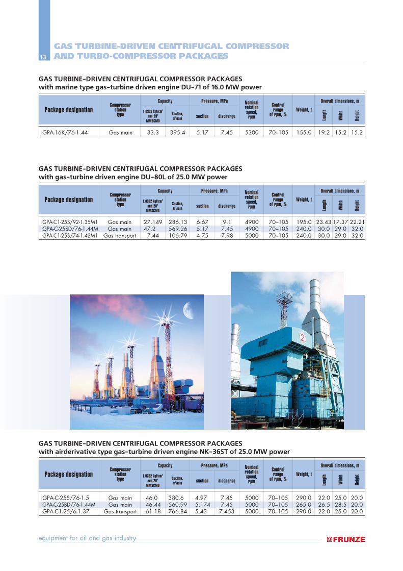
GAS TURBINE-DRIVEN CENTRIFUGAL COMPRESSOR PACKAGES with marine type gas-turbine driven engine DU-71 of 16.0 MW power
GPA-16K/76-1.44 Gas main 33.3 395.4 5.17 7.45 5300 70ñ105 155.0 19.2 15.2 15.2
Package designationCompressor
station type
Weight, tNominalrotationspeed,
rpm Leng
th
Wid
th
Heig
ht
Control range
of rpm, %
Overall dimensions, mCapacity
1.0332 kgf/cm2
and 200
MMSCMD
Suction, m3/min
Pressure, MPa
suction discharge
GAS TURBINE-DRIVEN CENTRIFUGAL COMPRESSOR PACKAGES with airderivative type gas-turbine driven engine NK-36ST of 25.0 MW power
GPA-C-25S/76-1.5 Gas main 46.0 380.6 4.97 7.45 5000 70ñ105 290.0 22.0 25.0 20.0GPA-C-25BD/76-1.44M Gas main 46.44 560.99 5.174 7.45 5000 70ñ105 265.0 26.5 28.5 20.0GPA-C1-25/6-1.37 Gas transport 61.18 766.84 5.43 7.453 5000 70ñ105 290.0 22.0 25.0 20.0
Package designationCompressor
station type
Weight, tNominalrotationspeed,
rpm Leng
th
Wid
th
Heig
ht
Control range
of rpm, %
Overall dimensions, mCapacity
1.0332 kgf/cm2
and 200
MMSCMD
Suction, m3/min
Pressure, MPa
suction discharge
GAS TURBINE-DRIVEN CENTRIFUGAL COMPRESSOR AND TURBO-COMPRESSOR PACKAGES
GAS TURBINE-DRIVEN CENTRIFUGAL COMPRESSOR PACKAGES with gas-turbine driven engine DU-80L of 25.0 MW power
Package designationCompressor
station type
Weight, tNominalrotationspeed,
rpm Leng
th
Wid
th
Heig
ht
Control range
of rpm, %
Overall dimensions, mCapacity
1.0332 kgf/cm2
and 200
MMSCMD
Suction, m3/min
Pressure, MPa
suction discharge
GPA-C1-25S/92-1.35M1 Gas main 27.149 286.13 6.67 9.1 4900 70ñ105 195.0 23.43 17.37 22.21GPA-C-25SD/76-1.44M Gas main 47.2 569.26 5.17 7.45 4900 70ñ105 240.0 30.0 29.0 32.0GPA-C1-25S/74-1.42M1 Gas transport 7.44 106.79 4.75 7.98 5000 70ñ105 240.0 30.0 29.0 32.0
catalog of products
14
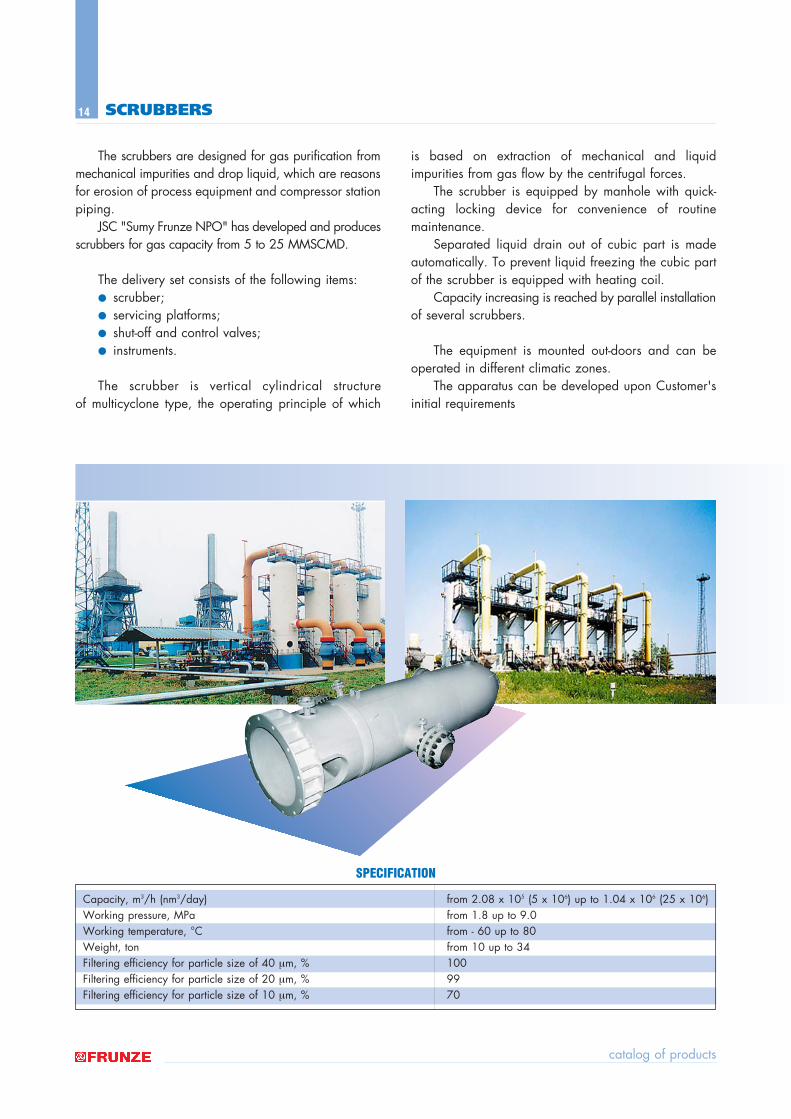
The scrubbers are designed for gas purification frommechanical impurities and drop liquid, which are reasonsfor erosion of process equipment and compressor stationpiping.
JSC "Sumy Frunze NPO" has developed and producesscrubbers for gas capacity from 5 to 25 MMSCMD.
The delivery set consists of the following items:● scrubber;● servicing platforms;● shut-off and control valves;● instruments.
The scrubber is vertical cylindrical structure of multicyclone type, the operating principle of which
is based on extraction of mechanical and liquid impurities from gas flow by the centrifugal forces.
The scrubber is equipped by manhole with quick-acting locking device for convenience of routine maintenance.
Separated liquid drain out of cubic part is madeautomatically. To prevent liquid freezing the cubic partof the scrubber is equipped with heating coil.
Capacity increasing is reached by parallel installationof several scrubbers.
The equipment is mounted out-doors and can beoperated in different climatic zones.
The apparatus can be developed upon Customer'sinitial requirements
SCRUBBERS
Capacity, m3/h (nm3/day) from 2.08 x 10⁵ (5 x 10⁶) up to 1.04 x 10⁶ (25 x 106)Working pressure, MPa from 1.8 up to 9.0Working temperature, ∞C from - 60 up to 80Weight, ton from 10 up to 34Filtering efficiency for particle size of 40 µm, % 100Filtering efficiency for particle size of 20 µm, % 99Filtering efficiency for particle size of 10 µm, % 70
SPECIFICATION
equipment for oil and gas industry
15
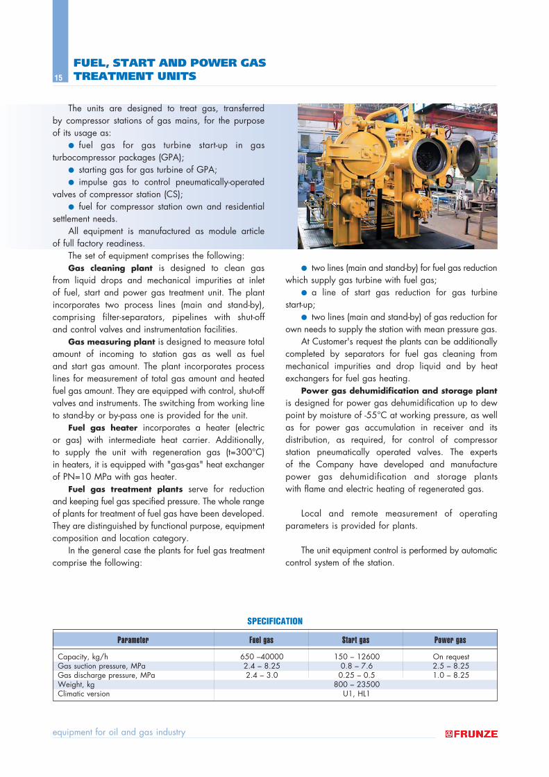
The units are designed to treat gas, transferred by compressor stations of gas mains, for the purpose of its usage as:
● fuel gas for gas turbine start-up in gas turbocompressor packages (GPA);
● starting gas for gas turbine of GPA; ● impulse gas to control pneumatically-operated
valves of compressor station (CS); ● fuel for compressor station own and residential
settlement needs. All equipment is manufactured as module article
of full factory readiness.The set of equipment comprises the following:Gas cleaning plant is designed to clean gas
from liquid drops and mechanical impurities at inlet of fuel, start and power gas treatment unit. The plantincorporates two process lines (main and stand-by),comprising filter-separators, pipelines with shut-off and control valves and instrumentation facilities.
Gas measuring plant is designed to measure totalamount of incoming to station gas as well as fuel and start gas amount. The plant incorporates processlines for measurement of total gas amount and heatedfuel gas amount. They are equipped with control, shut-offvalves and instruments. The switching from working lineto stand-by or by-pass one is provided for the unit.
Fuel gas heater incorporates a heater (electric or gas) with intermediate heat carrier. Additionally, to supply the unit with regeneration gas (t=300∞C) in heaters, it is equipped with "gas-gas" heat exchangerof PN=10 MPa with gas heater.
Fuel gas treatment plants serve for reduction and keeping fuel gas specified pressure. The whole rangeof plants for treatment of fuel gas have been developed.They are distinguished by functional purpose, equipmentcomposition and location category.
In the general case the plants for fuel gas treatmentcomprise the following:
● two lines (main and stand-by) for fuel gas reductionwhich supply gas turbine with fuel gas;
● a line of start gas reduction for gas turbine start-up;
● two lines (main and stand-by) of gas reduction forown needs to supply the station with mean pressure gas.
At Customer's request the plants can be additionallycompleted by separators for fuel gas cleaning frommechanical impurities and drop liquid and by heatexchangers for fuel gas heating.
Power gas dehumidification and storage plantis designed for power gas dehumidification up to dewpoint by moisture of -55∞C at working pressure, as wellas for power gas accumulation in receiver and its distribution, as required, for control of compressor station pneumatically operated valves. The experts of the Company have developed and manufacturepower gas dehumidification and storage plants with flame and electric heating of regenerated gas.
Local and remote measurement of operatingparameters is provided for plants.
The unit equipment control is performed by automaticcontrol system of the station.
FUEL, START AND POWER GAS TREATMENT UNITS
Capacity, kg/h 650 ñ40000 150 ñ 12600 On requestGas suction pressure, MPa 2.4 ñ 8.25 0.8 ñ 7.6 2.5 ñ 8.25Gas discharge pressure, MPa 2.4 ñ 3.0 0.25 ñ 0.5 1.0 ñ 8.25Weight, kg 800 ñ 23500Climatic version U1, HL1
SPECIFICATION
Parameter Fuel gas Start gas Power gas
catalog of products
16
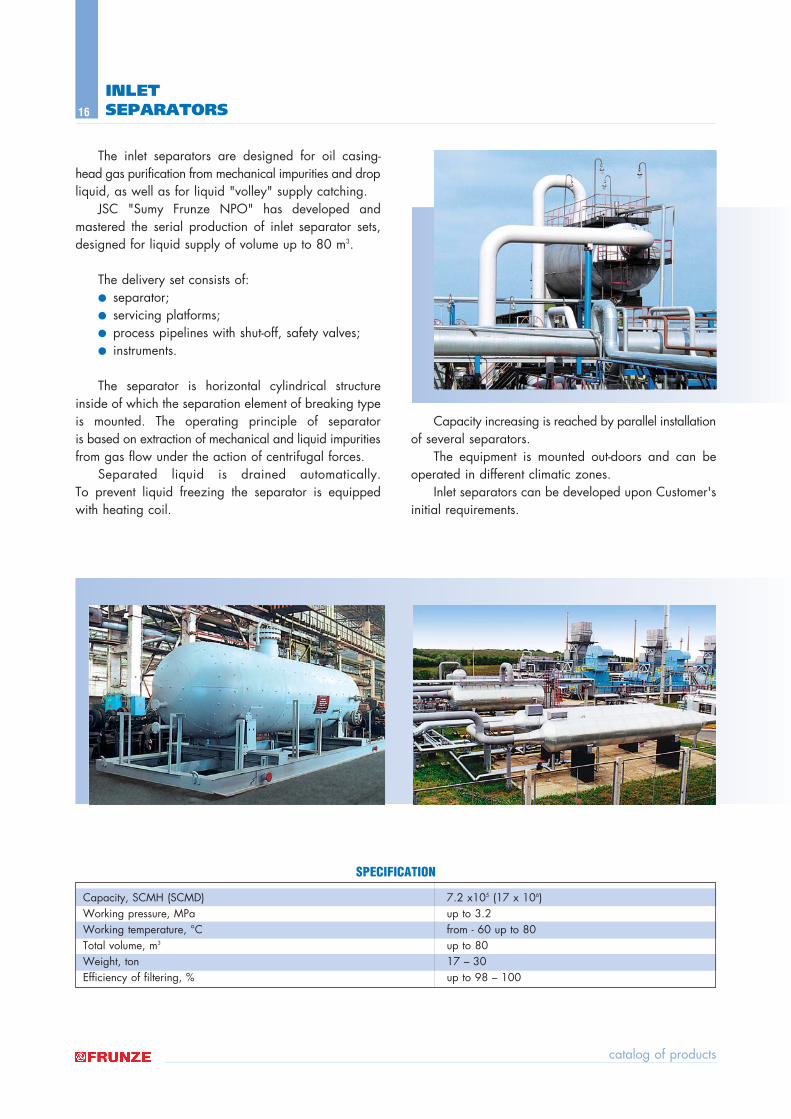
The inlet separators are designed for oil casing-head gas purification from mechanical impurities and dropliquid, as well as for liquid "volley" supply catching.
JSC "Sumy Frunze NPO" has developed and mastered the serial production of inlet separator sets,designed for liquid supply of volume up to 80 m3.
The delivery set consists of:● separator;● servicing platforms;● process pipelines with shut-off, safety valves;● instruments.
The separator is horizontal cylindrical structureinside of which the separation element of breaking typeis mounted. The operating principle of separator is based on extraction of mechanical and liquid impuritiesfrom gas flow under the action of centrifugal forces.
Separated liquid is drained automatically.To prevent liquid freezing the separator is equippedwith heating coil.
Capacity increasing is reached by parallel installationof several separators.
The equipment is mounted out-doors and can beoperated in different climatic zones.
Inlet separators can be developed upon Customer'sinitial requirements.
INLET SEPARATORS
Capacity, SCMH (SCMD) 7.2 x10⁵ (17 x 106)Working pressure, MPa up to 3.2Working temperature, ∞C from - 60 up to 80Total volume, m3 up to 80Weight, ton 17 ñ 30Efficiency of filtering, % up to 98 ñ 100
SPECIFICATION
equipment for oil and gas industry
17
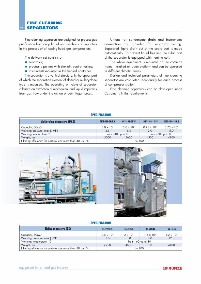
Fine cleaning separators are designed for process gaspurification from drop liquid and mechanical impuritiesin the process of oil casing-head gas compression.
The delivery set consists of:● separator;● process pipelines with shut-off, control valves;● instruments mounted in the heated container. The separator is a vertical structure, in the upper part
of which the separation element of slotted or multicyclonetype is mounted. The operating principle of separator is based on extraction of mechanical and liquid impuritiesfrom gas flow under the action of centrifugal forces.
Unions for condensate drain and instrumentsconnection are provided for separator casing.Separated liquid drain out of the cubic part is madeautomatically. To prevent liquid freezing the cubic partof the separator is equipped with heating coil.
The whole equipment is mounted on the commonframe, installed on open platform and can be operatedin different climatic zones.
Design and technical parameters of fine cleaningseparator are calculated individually for each processof compressor station.
Fine cleaning separators can be developed uponCustomer's initial requirements.
FINE CLEANING SEPARATORS
Capacity, SCMD 3.0 x 10⁶ 3.0 x 10⁶ 0.75 x 10⁶ 0.75 x 10⁶
Working pressure (max.), MPa 2.5 6.3 2.0 5.0Working temperature, ∞C from - 40 up to 80 from - 60 up to 80Weight, ton 5000 5600 4500 4900Filtering efficiency for particle size more than 40 µm, % to 100
MCS−100−56/2.5 MCS−100−20/6.3 MCS−100−19/25 MCS−100−10/6.3
Capacity, SCMD 2.5 x 10⁶ 2 x 10⁶ 1.5 x 10⁶ 1.2 x 10⁶
Working pressure (max.), MPa 1.6 3.0 8.0 12.0Working temperature, ∞C from - 60 up to 80Weight, ton 7200 4500 3100 4400Filtering efficiency for particle size more than 40 µm, % to 100
SS 1400/16 SS 700/30 SS 700/80 SS 11/2A
SPECIFICATION
SPECIFICATION
Multicyclone separators (MCS)
Slotted separators (SS)
catalog of products
18
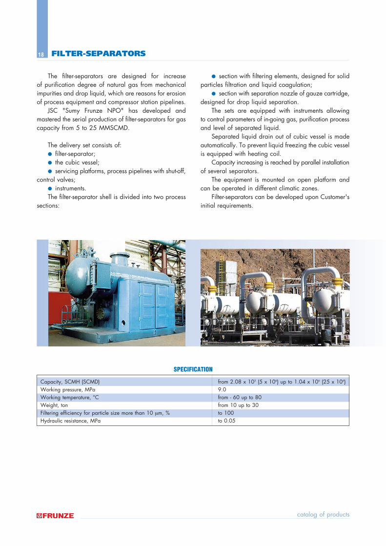
The filter-separators are designed for increase of purification degree of natural gas from mechanicalimpurities and drop liquid, which are reasons for erosionof process equipment and compressor station pipelines.
JSC "Sumy Frunze NPO" has developed and mastered the serial production of filter-separators for gascapacity from 5 to 25 MMSCMD.
The delivery set consists of:● filter-separator;● the cubic vessel;● servicing platforms, process pipelines with shut-off,
control valves;● instruments. The filter-separator shell is divided into two process
sections:
● section with filtering elements, designed for solidparticles filtration and liquid coagulation;
● section with separation nozzle of gauze cartridge,designed for drop liquid separation.
The sets are equipped with instruments allowing to control parameters of in-going gas, purification processand level of separated liquid.
Separated liquid drain out of cubic vessel is madeautomatically. To prevent liquid freezing the cubic vesselis equipped with heating coil.
Capacity increasing is reached by parallel installationof several separators.
The equipment is mounted on open platform andcan be operated in different climatic zones.
Filter-separators can be developed upon Customer'sinitial requirements.
FILTER-SEPARATORS
Capacity, SCMH (SCMD) from 2.08 x 10⁵ (5 x 10⁶) up to 1.04 x 10⁶ (25 x 106)Working pressure, MPa 9.0Working temperature, ∞C from - 60 up to 80Weight, ton from 10 up to 30Filtering efficiency for particle size more than 10 µm, % to 100Hydraulic resistance, MPa to 0.05
SPECIFICATION
equipment for oil and gas industry
19
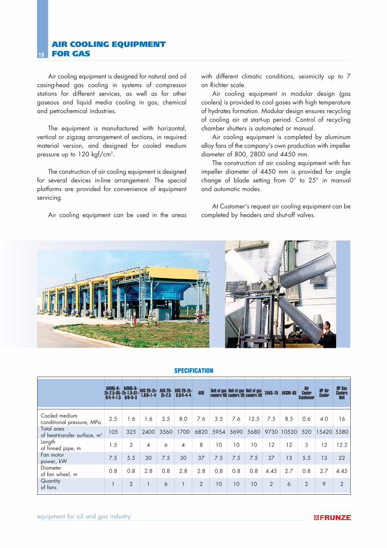
Air cooling equipment is designed for natural and oilcasing-head gas cooling in systems of compressor stations for different services, as well as for othergaseous and liquid media cooling in gas, chemical and petrochemical industries.
The equipment is manufactured with horizontal, vertical or zigzag arrangement of sections, in requiredmaterial version, and designed for cooled medium pressure up to 120 kgf/cm2.
The construction of air cooling equipment is designedfor several devices in-line arrangement. The specialplatforms are provided for convenience of equipmentservicing.
Air cooling equipment can be used in the areas
with different climatic conditions, seismicity up to 7 on Richter scale.
Air cooling equipment in modular design (gascoolers) is provided to cool gases with high temperatureof hydrates formation. Modular design ensures recyclingof cooling air at start-up period. Control of recyclingchamber shutters is automated or manual.
Air cooling equipment is completed by aluminumalloy fans of the company's own production with impellerdiameter of 800, 2800 and 4450 mm.
The construction of air cooling equipment with fanimpeller diameter of 4450 mm is provided for anglechange of blade setting from 0∞ to 25∞ in manual and automatic modes.
At Customer's request air cooling equipment can becompleted by headers and shut-off valves.
AIR COOLING EQUIPMENT FOR GAS
SPECIFICATION
Cooled mediumconditional pressure, MPa 2.5 1.6 1.6 2.5 8.0 7.6 3.5 7.6 12.5 7.5 8.5 0.6 4.0 16
Total areaof heat-transfer surface, m2 105 325 2400 3560 1700 6820 5954 5690 5680 9730 10530 520 15420 5380
Lengthof finned pipe, m 1.5 3 4 6 4 8 10 10 10 12 12 3 12 12.2
Fan motorpower, kW 7.5 5.5 30 7.5 30 37 7.5 7.5 7.5 37 13 5.5 13 22
Diameterof fan wheel, m 0.8 0.8 2.8 0.8 2.8 2.8 0,8 0.8 0.8 4.45 2.7 0.8 2.7 4.45
Quantityof fans 1 2 1 6 1 2 10 10 10 2 6 2 9 2
AVMG−9−Zh−2.5−B5−B/4−4−1.5
AVMG−9−Zh−1.6−B1−
B/6−6−3AVG 20−Zh−1.6/6−1−4
AVG 20−Zh−2.5
AVG 20−Zh−8.0/4−4−4 AVO Unit of gas
coolers NDUnit of gascoolers VD
Unit of gascoolers VD 2AVG−75 AVGM−85
AirCooler
CondenserHP AirCooler
HP GasCoolers
Unit
catalog of products
20
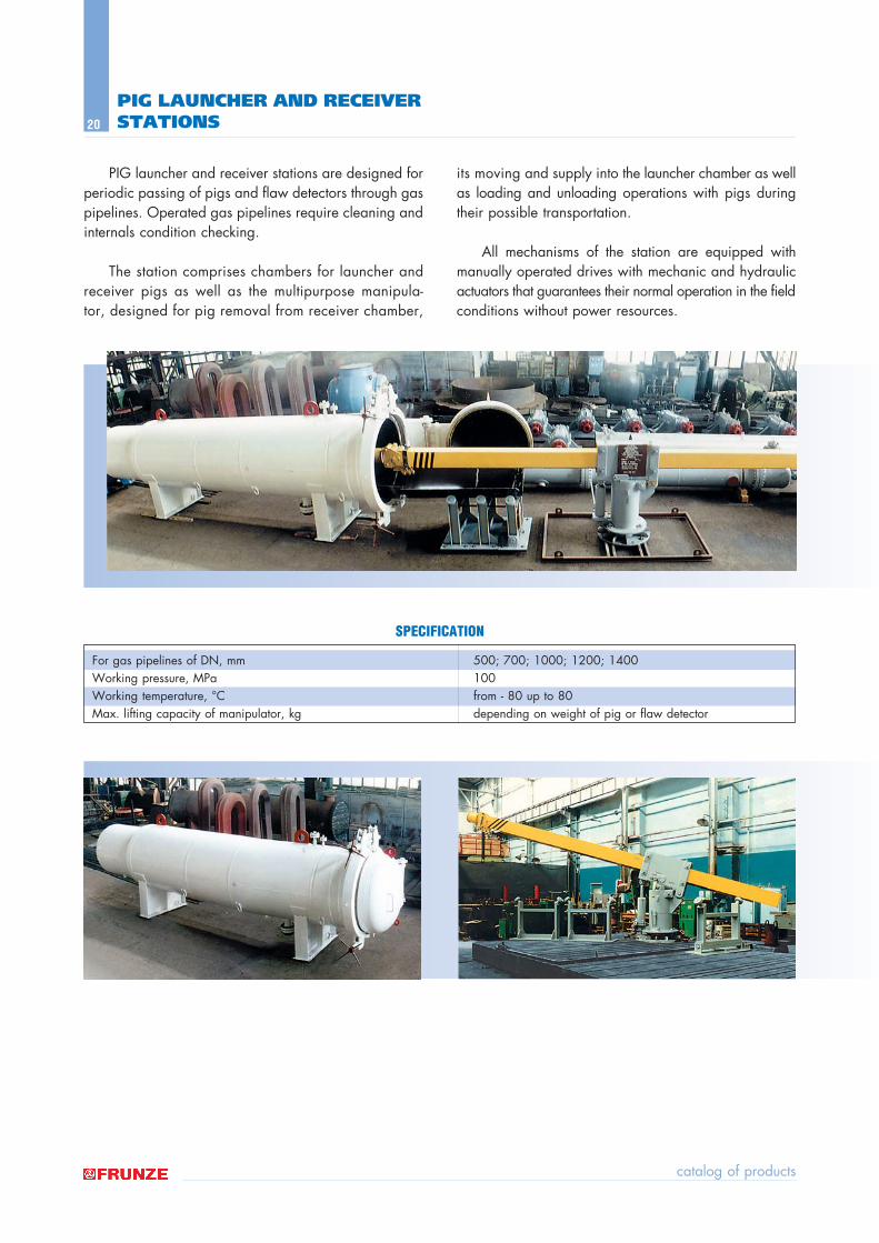
PIG launcher and receiver stations are designed for periodic passing of pigs and flaw detectors through gaspipelines. Operated gas pipelines require cleaning andinternals condition checking.
The station comprises chambers for launcher andreceiver pigs as well as the multipurpose manipula-tor, designed for pig removal from receiver chamber,
its moving and supply into the launcher chamber as wellas loading and unloading operations with pigs duringtheir possible transportation.
All mechanisms of the station are equipped withmanually operated drives with mechanic and hydraulicactuators that guarantees their normal operation in the fieldconditions without power resources.
PIG LAUNCHER AND RECEIVER STATIONS
For gas pipelines of DN, mm 500; 700; 1000; 1200; 1400Working pressure, MPa 100Working temperature, ∞C from - 80 up to 80Max. lifting capacity of manipulator, kg depending on weight of pig or flaw detector
SPECIFICATION
equipment for oil and gas industry
21
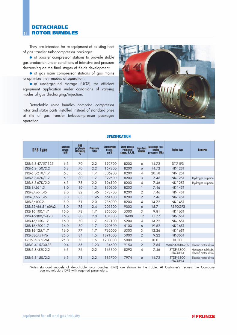
They are intended for re-equipment of existing fleetof gas transfer turbocompressor packages:
● at booster compressor stations to provide stablegas production under conditions of intensive bed pressuredecreasing on the final stages of fields development;
● at gas main compressor stations of gas mains to optimize their modes of operation;
● at underground storage (UGS) for efficient equipment application under conditions of varyingmodes of gas discharging/injection.
Detachable rotor bundles comprise compressorrotor and stator parts installed instead of standard onesat site of gas transfer turbocompressor packages operation.
DETACHABLE ROTOR BUNDLES
DRB-6.3-47/57-125 6.3 70 2.2 192700 8200 6 14.72 DT-71P«DRB-6.3-150/2.2 6.3 70 2.2 157200 8200 6 14.72 NK-12STDRB-6.3-210/1.7 6.3 68 1.7 306200 8200 4 20.58 NK-12STDRB-6.3-67K/1.7 6.3 80 1.7 329500 8200 3 7.46 NK-12ST Hydrogen sulphide
DRB-6.3-67K/2.2 6.3 75 2.2 194100 8200 4 7.46 NK-12ST Hydrogen sulphide
DRB-8/56-1.3 8.0 80 1.3 830300 8200 1 7.46 NK-14STDRB-8/56-1.45 8.0 82 1.45 573700 8200 2 7.46 NK-14STDRB-8/76-1.45 8.0 83 1.45 661400 8200 2 7.46 NK-14STDRB-8/100-2 8.0 71 2.0 236000 8200 4 14.72 NK-14STDRB-52/66.5-160M2 8.0 75 2.4 203300 9000 6 15.7 PS-90GP«DRB-16-100/1.7 16.0 78 1.7 855000 5300 3 9.81 NK-16STDRB-16-300/6-120 16.0 80 2.0 104800 10400 12 11.77 NK-16STDRB-16/150-1.7 16.0 70 1.7 677100 5200 4 14.72 NK-16STDRB-16/200-1.7 16.0 80 1.7 920800 5100 6 19.62 NK-16STDRB-16-125/1.7 16.0 77 1.7 762000 5300 3 12.26 NK-16STDRB-580/51-76 25.0 84 1.5 1891000 5000 2 9.22 NK-36STGC2-350/58-94 25.0 78 1.61 1200000 5000 - 10.0 DU80LDRB-0.4-15/30-38 0.4 65 1.23 34600 9150 2 7.85 VA02-450LB-2U2 Electric motor drive
DRB-6.3/32K-2.2 6.3 76 2.2 163300 8290 4 7.46 STDP-6300- Hydrogen sulphide,2BCUHL4 electric motor drive
DRB-6.3-150/2.2 6.3 73 2.2 185700 7974 6 14.72 STDP-6300- Electric motor drive2BCUHL4
Notes: standard models of detachable rotor bundles (DRB) are shown in the Table. At Customer's request the Company can manufacture DRB with required parameters.
DRB typeNominalpower,
MW
DRB polytropicefficiency,
%
Pressureratio
Commercialoutput, sm3/h
Shaft nominalrotational
speed, R.P.M.Impellersnumber
Maximum finalcasing
pressure, MPaEngine type Remarks
SPECIFICATION
catalog of products
22
GAS COMPLEX TREATMENT PLANTS
Gas capacity, MMSCMD 1.0 ñ 2.0 2.0 ñ 3.0Condensate capacity, t/h 8.0 ñ 12.0 15.0 ñ 30.0Gas pressure:
ñ inlet, MPa 8.5 ñ 16.0 8.5 ñ 16.0ñ outlet, MPa 5.5 ñ 7.5 5.5 ñ 7.5
Condensate outlet pressure, MPa 0.6* 0.6*
Note: * ñ to be clarified on Customer's demand
Parameter UKPG−2.0 UKPG−3.0
SPECIFICATIONS AS EXAMPLE OF UKPG−2.0 AND UKPG−3.0
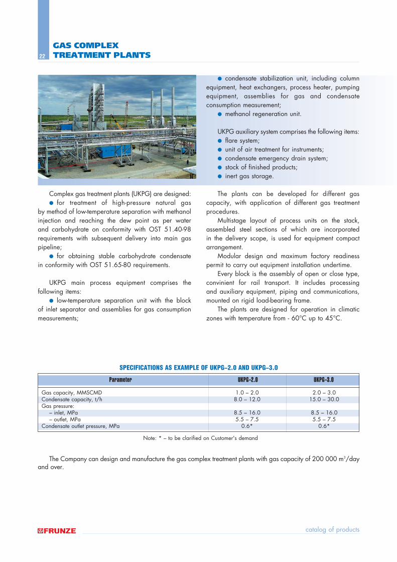
Complex gas treatment plants (UKPG) are designed:● for treatment of high-pressure natural gas
by method of low-temperature separation with methanolinjection and reaching the dew point as per water and carbohydrate on conformity with OST 51.40-98requirements with subsequent delivery into main gaspipeline;
● for obtaining stable carbohydrate condensate in conformity with OST 51.65-80 requirements.
UKPG main process equipment comprises the following items:
● low-temperature separation unit with the block of inlet separator and assemblies for gas consumptionmeasurements;
● condensate stabilization unit, including columnequipment, heat exchangers, process heater, pumpingequipment, assemblies for gas and condensate consumption measurement;
● methanol regeneration unit.
UKPG auxiliary system comprises the following items:● flare system;● unit of air treatment for instruments;● condensate emergency drain system;● stock of finished products;● inert gas storage.
The plants can be developed for different gascapacity, with application of different gas treatmentprocedures.
Multistage layout of process units on the stack,assembled steel sections of which are incorporated in the delivery scope, is used for equipment compactarrangement.
Modular design and maximum factory readinesspermit to carry out equipment installation undertime.
Every block is the assembly of open or close type,convinient for rail transport. It includes processing and auxiliary equipment, piping and communications,mounted on rigid load-bearing frame.
The plants are designed for operation in climaticzones with temperature from - 60∞C up to 45∞C.
The Company can design and manufacture the gas complex treatment plants with gas capacity of 200 000 m3/dayand over.
equipment for oil and gas industry
23
GAS TREATMENT PLANTS
Applied procedure Heavy hydrocarbons Low temperature oil absorption separation
Gas capacity, mln. m3/year 50 500Commodity output natural gas as to OST 51.40-98
liquefied propane-butanestabilized casing-head gasoline
Site area, hectare 0.6 1.6
Parameter UPG−50 UPG−500
SPECIFICATIONS AS EXAMPLE OF UPG−50 AND UPG–500
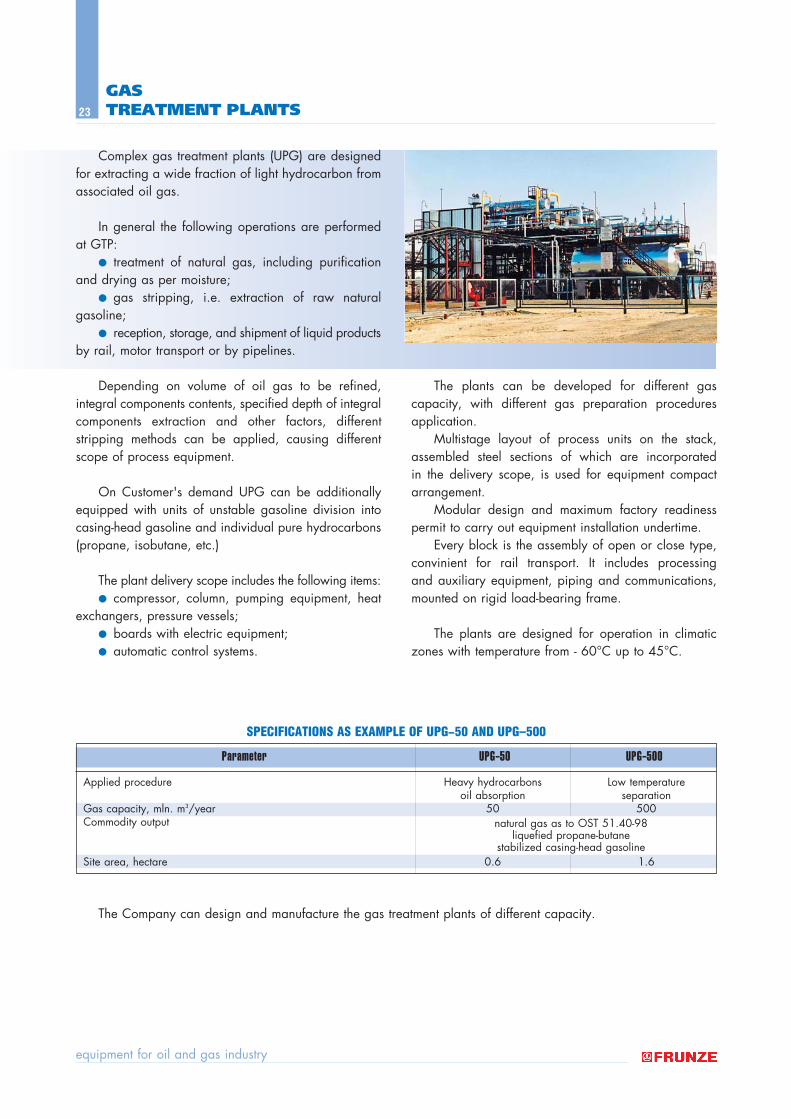
Complex gas treatment plants (UPG) are designedfor extracting a wide fraction of light hydrocarbon fromassociated oil gas.
In general the following operations are performedat GTP:
● treatment of natural gas, including purificationand drying as per moisture;
● gas stripping, i.e. extraction of raw natural gasoline;
● reception, storage, and shipment of liquid productsby rail, motor transport or by pipelines.
Depending on volume of oil gas to be refined, integral components contents, specified depth of integralcomponents extraction and other factors, different stripping methods can be applied, causing differentscope of process equipment.
On Customer's demand UPG can be additionallyequipped with units of unstable gasoline division intocasing-head gasoline and individual pure hydrocarbons(propane, isobutane, etc.)
The plant delivery scope includes the following items:● compressor, column, pumping equipment, heat
exchangers, pressure vessels;● boards with electric equipment;● automatic control systems.
The plants can be developed for different gascapacity, with different gas preparation proceduresapplication.
Multistage layout of process units on the stack,assembled steel sections of which are incorporated in the delivery scope, is used for equipment compactarrangement.
Modular design and maximum factory readinesspermit to carry out equipment installation undertime.
Every block is the assembly of open or close type,convinient for rail transport. It includes processing and auxiliary equipment, piping and communications,mounted on rigid load-bearing frame.
The plants are designed for operation in climaticzones with temperature from - 60∞C up to 45∞C.
The Company can design and manufacture the gas treatment plants of different capacity.
catalog of products
24
CONDENSATE AND OIL PROCESSING PLANTSWITH THE CAPACITY FROM 5 TO 500 THOUSAND TONS PER YEAR
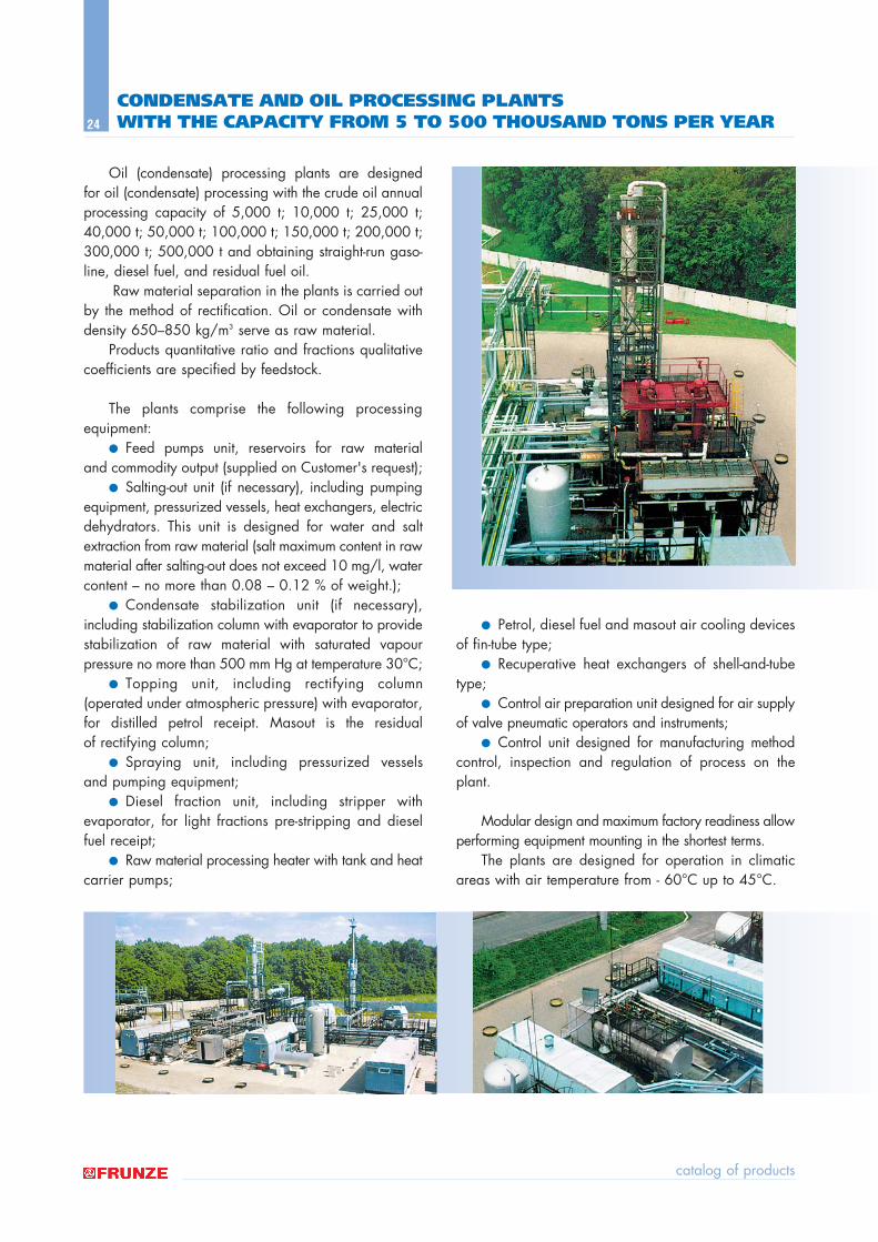
Oil (condensate) processing plants are designed for oil (condensate) processing with the crude oil annualprocessing capacity of 5,000 t; 10,000 t; 25,000 t;40,000 t; 50,000 t; 100,000 t; 150,000 t; 200,000 t;300,000 t; 500,000 t and obtaining straight-run gaso-line, diesel fuel, and residual fuel oil.
Raw material separation in the plants is carried outby the method of rectification. Oil or condensate withdensity 650ñ850 kg/m3 serve as raw material.
Products quantitative ratio and fractions qualitativecoefficients are specified by feedstock.
The plants comprise the following processing equipment:
● Feed pumps unit, reservoirs for raw material and commodity output (supplied on Customer's request);
● Salting-out unit (if necessary), including pumpingequipment, pressurized vessels, heat exchangers, electricdehydrators. This unit is designed for water and saltextraction from raw material (salt maximum content in rawmaterial after salting-out does not exceed 10 mg/l, watercontent ñ no more than 0.08 ñ 0.12 % of weight.);
● Condensate stabilization unit (if necessary),including stabilization column with evaporator to providestabilization of raw material with saturated vapour pressure no more than 500 mm Hg at temperature 30∞C;
● Topping unit, including rectifying column (operated under atmospheric pressure) with evaporator,for distilled petrol receipt. Masout is the residual of rectifying column;
● Spraying unit, including pressurized vessels and pumping equipment;
● Diesel fraction unit, including stripper with evaporator, for light fractions pre-stripping and dieselfuel receipt;
● Raw material processing heater with tank and heatcarrier pumps;
● Petrol, diesel fuel and masout air cooling devicesof fin-tube type;
● Recuperative heat exchangers of shell-and-tubetype;
● Control air preparation unit designed for air supplyof valve pneumatic operators and instruments;
● Control unit designed for manufacturing methodcontrol, inspection and regulation of process on theplant.
Modular design and maximum factory readiness allowperforming equipment mounting in the shortest terms.
The plants are designed for operation in climaticareas with air temperature from - 60∞C up to 45∞C.
equipment for oil and gas industry
25
COMPLEX OF PROCESS EQUIPMENT FOR REFINERIES
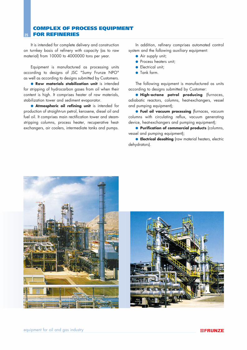
It is intended for complete delivery and constructionon turnkey basis of refinery with capacity (as to rawmaterial) from 10000 to 4000000 tons per year.
Equipment is manufactured as processing unitsaccording to designs of JSC "Sumy Frunze NPO" as well as according to designs submitted by Customers.
● Raw materials stabilization unit is intendedfor stripping of hydrocarbon gases from oil when theircontent is high. It comprises heater of raw materials, stabilization tower and sediment evaporator.
● Atmospheric oil refining unit is intended forproduction of straight-run petrol, kerosene, diesel oil andfuel oil. It comprises main rectification tower and steam-stripping columns, process heater, recuperative heat-exchangers, air coolers, intermediate tanks and pumps.
In addition, refinery comprises automated controlsystem and the following auxiliary equipment:
● Air supply unit;● Process heaters unit;● Electrical unit;● Tank farm.
The following equipment is manufactured as unitsaccording to designs submitted by Customer:
● High-octane petrol producing (furnaces, adiabatic reactors, columns, heat-exchangers, vesseland pumping equipment);
● Fuel oil vacuum processing (furnaces, vacuumcolumns with circulating reflux, vacuum generatingdevice, heat-exchangers and pumping equipment);
● Purification of commercial products (columns,vessel and pumping equipment);
● Electrical desalting (raw material heaters, electricdehydrators).
catalog of products
26
EQUIPMENT FOR OIL TERMINALS
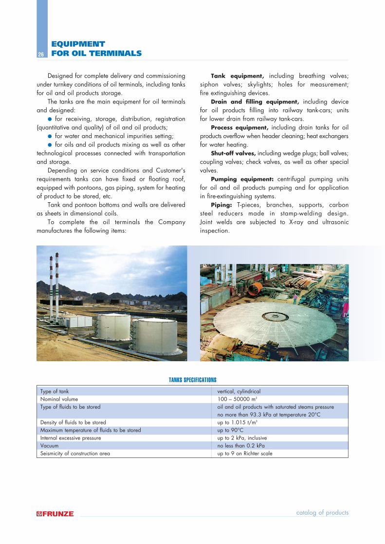
Type of tank vertical, cylindrical Nominal volume 100 ñ 50000 m3
Type of fluids to be stored oil and oil products with saturated steams pressure no more than 93.3 kPa at temperature 20∞C
Density of fluids to be stored up to 1.015 t/m3
Maximum temperature of fluids to be stored up to 90∞CInternal excessive pressure up to 2 kPa, inclusive Vacuum no less than 0.2 kPa Seismicity of construction area up to 9 on Richter scale
Designed for complete delivery and commissioningunder turnkey conditions of oil terminals, including tanksfor oil and oil products storage.
The tanks are the main equipment for oil terminalsand designed:
● for receiving, storage, distribution, registration(quantitative and quality) of oil and oil products;
● for water and mechanical impurities setting; ● for oils and oil products mixing as well as other
technological processes connected with transportationand storage.
Depending on service conditions and Customer'srequirements tanks can have fixed or floating roof,equipped with pontoons, gas piping, system for heatingof product to be stored, etc.
Tank and pontoon bottoms and walls are deliveredas sheets in dimensional coils.
To complete the oil terminals the Company manufactures the following items:
Tank equipment, including breathing valves;siphon valves; skylights; holes for measurement; fire extinguishing devices.
Drain and filling equipment, including device for oil products filling into railway tank-cars; units for lower drain from railway tank-cars.
Process equipment, including drain tanks for oilproducts overflow when header cleaning; heat exchangersfor water heating.
Shut-off valves, including wedge plugs; ball valves;coupling valves; check valves, as well as other specialvalves.
Pumping equipment: centrifugal pumping unitsfor oil and oil products pumping and for application in fire-extinguishing systems.
Piping: T-pieces, branches, supports, carbonsteel reducers made in stamp-welding design. Joint welds are subjected to X-ray and ultrasonicinspection.
TANKS SPECIFICATIONS
equipment for oil and gas industry
27
CYLINDRICAL PRESSURE VESSELS FOR GASEOUS AND LIQUID MEDIUMS
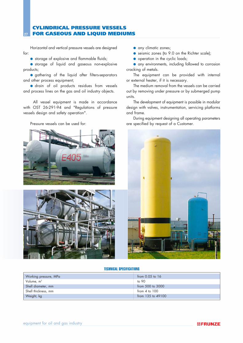
Horizontal and vertical pressure vessels are designedfor:
● storage of explosive and flammable fluids;● storage of liquid and gaseous non-explosive
products;● gathering of the liquid after filters-separators
and other process equipment; ● drain of oil products residues from vessels
and process lines on the gas and oil industry objects.
All vessel equipment is made in accordance with OST 26-291-94 and "Regulations of pressure vessels design and safety operation".
Pressure vessels can be used for:
● any climatic zones; ● seismic zones (to 9.0 on the Richter scale); ● operation in the cyclic loads;● any environments, including followed to corrosion
cracking of metals. The equipment can be provided with internal
or external heater, if it is necessary. The medium removal from the vessels can be carried
out by removing under pressure or by submerged pumpunits.
The development of equipment is possible in modulardesign with valves, instrumentation, servicing platformsand frame.
During equipment designing all operating parametersare specified by request of a Customer.
Working pressure, M–a from 0.05 to 16Volume, m3 to 90Shell diameter, mm from 500 to 3000Shell thickness, mm from 4 to 100Weight, kg from 135 to 49100
TECHNICAL SPECIFICATIONS
catalog of products
28
MODERNIZED SECTIONAL CENTRIFUGAL PUMPS OF CNS TYPE
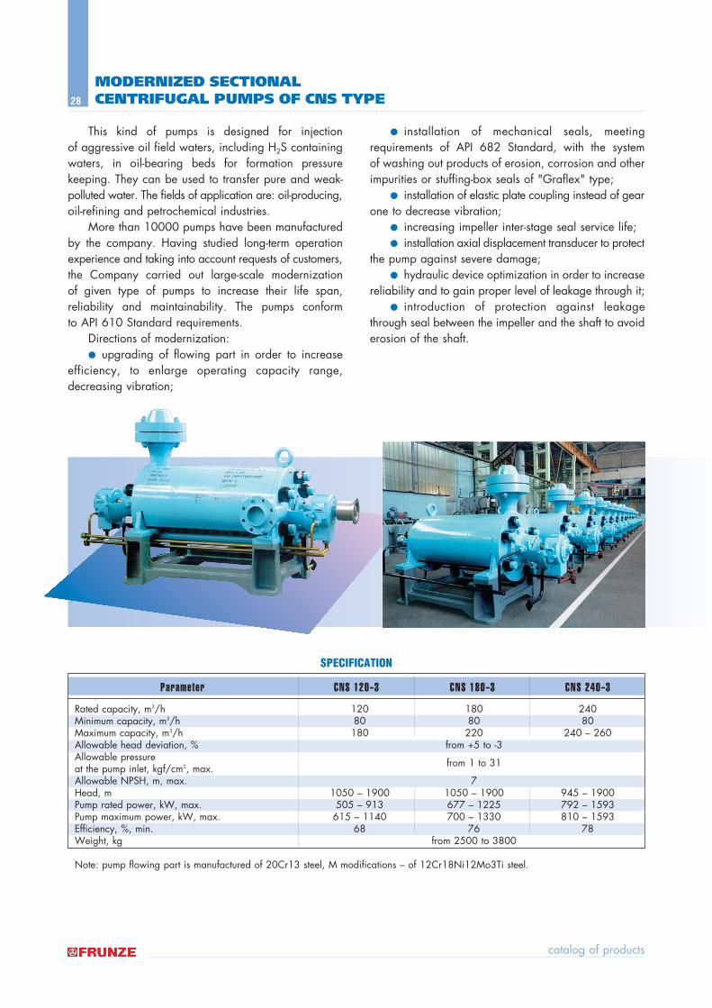
This kind of pumps is designed for injection of aggressive oil field waters, including H2S containingwaters, in oil-bearing beds for formation pressure keeping. They can be used to transfer pure and weak-polluted water. The fields of application are: oil-producing,oil-refining and petrochemical industries.
More than 10000 pumps have been manufacturedby the company. Having studied long-term operationexperience and taking into account requests of customers,the Company carried out large-scale modernization of given type of pumps to increase their life span, reliability and maintainability. The pumps conform to API 610 Standard requirements.
Directions of modernization:● upgrading of flowing part in order to increase
efficiency, to enlarge operating capacity range,decreasing vibration;
● installation of mechanical seals, meeting requirements of API 682 Standard, with the system of washing out products of erosion, corrosion and otherimpurities or stuffing-box seals of "Graflex" type;
● installation of elastic plate coupling instead of gearone to decrease vibration;
● increasing impeller inter-stage seal service life;● installation axial displacement transducer to protect
the pump against severe damage;● hydraulic device optimization in order to increase
reliability and to gain proper level of leakage through it;● introduction of protection against leakage
through seal between the impeller and the shaft to avoiderosion of the shaft.
Rated capacity, m3/h 120 180 240Minimum capacity, m3/h 80 80 80Maximum capacity, m3/h 180 220 240 ñ 260Allowable head deviation, % from +5 to -3Allowable pressure from 1 to 31at the pump inlet, kgf/cm2, max.Allowable NPSH, m, max. 7Head, m 1050 ñ 1900 1050 ñ 1900 945 ñ 1900Pump rated power, kW, max. 505 ñ 913 677 ñ 1225 792 ñ 1593Pump maximum power, kW, max. 615 ñ 1140 700 ñ 1330 810 ñ 1593Efficiency, %, min. 68 76 78Weight, kg from 2500 to 3800
Note: pump flowing part is manufactured of 20Cr13 steel, M modifications ñ of 12Cr18Ni12Mo3Ti steel.
SPECIFICATION
Parameter CNS 120−3 CNS 180 −3 CNS 240 −3
equipment for oil and gas industry
29
Volumetic feed of initial product for a clay separator, m3/h, no more than:when removing clay from weighted mud with a density to 1.1 g/cm3 18when regenerating weighted mud with a density:
to 1.5 g/cm3 6to 2.0 g/cm3 3
Degree of clay removal, %, no less than 80Degree of barytic weighting agent regeneration, %, no less than 90Maximum inner centrifuge diameter, mm 500Ratio of rotor working length to inner diameter 1.86Rated power, kW, no more than 37Weight, kg, no more than 4000
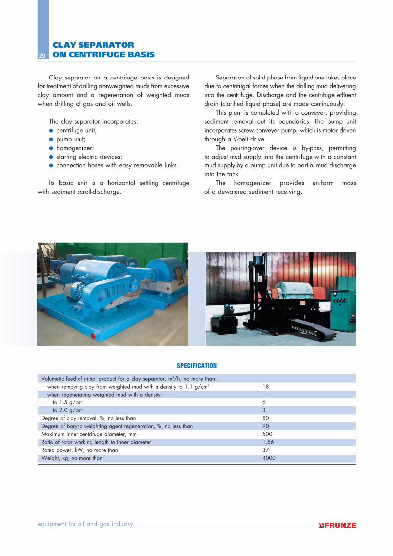
Clay separator on a centrifuge basis is designed for treatment of drilling nonweighted muds from excessiveclay amount and a regeneration of weighted mudswhen drilling of gas and oil wells.
The clay separator incorporates:● centrifuge unit; ● pump unit; ● homogenizer; ● starting electric devices; ● connection hoses with easy removable links.
Its basic unit is a horizontal settling centrifuge with sediment scroll-discharge.
Separation of solid phase from liquid one takes placedue to centrifugal forces when the drilling mud deliveringinto the centrifuge. Discharge and the centrifuge effluentdrain (clarified liquid phase) are made continuously.
This plant is completed with a conveyer, providingsediment removal out its boundaries. The pump unitincorporates screw conveyer pump, which is motor driventhrough a V-belt drive.
The pouring-over device is by-pass, permitting to adjust mud supply into the centrifuge with a constantmud supply by a pump unit due to partial mud dischargeinto the tank.
The homogenizer provides uniform mass of a dewatered sediment receiving.
CLAY SEPARATOR ON CENTRIFUGE BASIS
SPECIFICATION
catalog of products
30
WELL WORKOVER AND COMPLETION RIG OF AK-60 TYPE
Wheelbase Chassis KrAZ-63221-01 (6x6)Nominal lifting capacity, kN (t) 600 (60)Maximum lifting capacity (during releasing of stuck pipes), kN (t) 800 (80)Power of winch drive, kW 165.4Lifting speed, m/s 0.21 ñ 1.6Derrick height from the ground to crown block axis, m 20Rotor table opening diameter, mm 360Rotor P-165 opening diameter, mm 165Static load on rotor table, kN (tf) 800 (80)Rotor power with hydraulic drive, kW 80Rotational speed, rpm 20 ñ 100Overall dimensions in transported position, m 16.5 x 3.2 x 4.5Total weight of the rig in assembly, ton 34.2
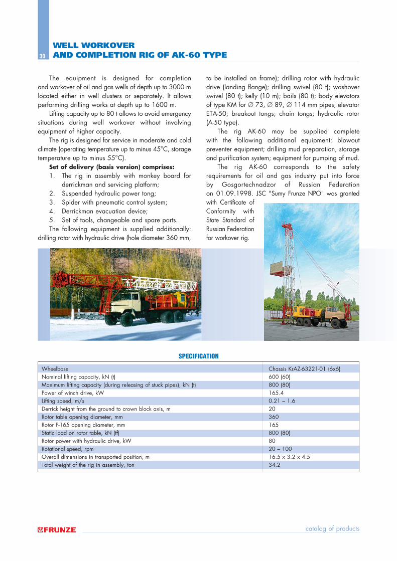
The equipment is designed for completion and workover of oil and gas wells of depth up to 3000 mlocated either in well clusters or separately. It allowsperforming drilling works at depth up to 1600 m.
Lifting capacity up to 80 t allows to avoid emergencysituations during well workover without involving equipment of higher capacity.
The rig is designed for service in moderate and coldclimate (operating temperature up to minus 45∞C, storagetemperature up to minus 55∞C).
Set of delivery (basis version) comprises:1. The rig in assembly with monkey board for
derrickman and servicing platform; 2. Suspended hydraulic power tong; 3. Spider with pneumatic control system; 4. Derrickman evacuation device; 5. Set of tools, changeable and spare parts. The following equipment is supplied additionally:
drilling rotor with hydraulic drive (hole diameter 360 mm,
to be installed on frame); drilling rotor with hydraulicdrive (landing flange); drilling swivel (80 t); washoverswivel (80 t); kelly (10 m); bails (80 t); body elevatorsof type KM for ∅ 73, ∅ 89, ∅ 114 mm pipes; elevatorETA-50; breakout tongs; chain tongs; hydraulic rotor (A-50 type).
The rig AK-60 may be supplied complete with the following additional equipment: blowout preventer equipment; drilling mud preparation, storageand purification system; equipment for pumping of mud.
The rig AK-60 corresponds to the safety requirements for oil and gas industry put into force by Gosgortechnadzor of Russian Federation on 01.09.1998. JSC "Sumy Frunze NPO" was grantedwith Certificate ofConformity withState Standard ofRussian Federationfor workover rig.
SPECIFICATION
equipment for oil and gas industry
31
Wheelbase MAZ-537G chassis (8 x 8)Nominal lifting capacity, kN (t) 800 (80)Short-time lifting capacity (during releasing of stuck pipes), kN (t) 1000 (100)Hoisting speed, m/s: 0.23 ñ 1.33Drive power, kW 426Derrick height from the ground to crown block axis, m 30Servicing platform height near wellhead, m 3.75Rotor table opening, mm 360Rotor power with hydraulic drive, kW 90Maximum pump pressure, MPa 16Speed of carrier moving, km/h 30Overall dimensions in transported position, m 17.5 x 3.2 x 4.7Total weight of the rig assembled, ton 10
WELL WORKOVER AND COMPLETION RIG OF KORO 1-80 TYPE
SPECIFICATION
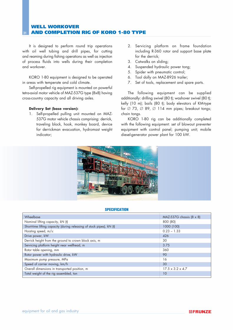
It is designed to perform round trip operations with oil well tubing and drill pipes, for cutting and reaming during fishing operations as well as injectionof process fluids into wells during their completion and workover.
KORO 1-80 equipment is designed to be operatedin areas with temperate and cold climate.
Self-propelled rig equipment is mounted on powerfultetra-axial motor vehicle of MAZ-537G type (8x8) havingcross-country capacity and all driving axles.
Delivery Set (base version):1. Self-propelled pulling unit mounted on MAZ-
537G motor vehicle chassis comprising: derrick,traveling block, hook, monkey board, devicefor derrickman evacuation, hydromast weightindicator;
2. Servicing platform on frame foundation including R-360 rotor and support base platefor the derrick;
3. Catwalks on sliding;4. Suspended hydraulic power tong;5. Spider with pneumatic control; 6. Tool dolly on MAZ-8926 trailer; 7. Set of tools, replacement and spare parts.
The following equipment can be supplied additionally: drilling swivel (80 t); washover swivel (80 t);kelly (10 m); bails (80 t); body elevators of KM-type for ∅ 73, ∅ 89, ∅ 114 mm pipes; breakout tongs;chain tongs.
KORO 1-80 rig can be additionally completed with the following equipment: set of blowout preventerequipment with control panel; pumping unit; mobilediesel-generator power plant for 100 kW.