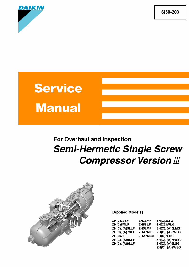
for overhaul and inspection semi-hermetic single screw ... · scope of application si50-203 2...
TRANSCRIPT
Head office:Umeda Center Bldg., 4-12, Nakazaki-Nishi 2-chome,Kita-ku, Osaka, 530-8323 Japan
Tokyo office:Shinjuku Sumitomo Bldg., 6-1 Nishi-Shinjuku2-chome, Shinjuku-ku, Tokyo, 163-0235 Japan
Zandvoordestraat 300, B-8400 Oostende, Belgium
« The specifications, designs, and information in this manual are subject to change without notice.
Printed in Japan 02/2003 AK
Semi-Hermetic Single Screw Compressor Version
For Overhaul and Inspection
[Applied Models]
ZH(C)3LSF ZH3LMF ZH(C)3LTGZH(C)5MLF ZH5SLF ZH(C)3WLGZH(C), (A)5LLF ZH5LMF ZH(C), (A)5LMGZH(C), (A)7SLF ZHA7MLF ZH(C), (A)5WLGZH(C)7LLF ZHA7MSGZH(C)7LSGZH(C), (A)9SLF ZH(C), (A)7WSGZH(C), (A)9LLF ZH(C), (A)9LSG ZH(C), (A)9WSG
Si50-203

Si50-203
Semi-Hermetic SingleSemi-Hermetic SingleSemi-Hermetic SingleSemi-Hermetic SingleScrew CompressorScrew CompressorScrew CompressorScrew Compressor
Version IIIVersion IIIVersion IIIVersion III
1. Scope of Application ...............................................................................22. Overhaul..................................................................................................33. Periodic Inspection..................................................................................4
3.1 Periodic Inspection Items and Intervals....................................................43.2 Periodic Inspection Instructions................................................................5
4. Overhaul Instructions ............................................................................104.1 Disassembly and Inspection...................................................................114.2 Replacing The Bearing...........................................................................204.3 Final Assembly .......................................................................................24
5. Airtightness Test ...................................................................................296. Charging Oil ..........................................................................................307. Caution in Test Operation .....................................................................318. Required Tools......................................................................................32
[Applicable Models]
ZH3LSF ZH3LMF ZHC3LSF ZH3LTG ZHC3LTGZH5MLF ZH5SLF ZHC5MLF ZH3WLG ZHC3WLGZH5LLF ZH5LMF ZHC5LLF ZHA5LLF ZH5LMG ZHC5LMG ZHA5LMGZH7SLF ZHC7SLF ZHA7SLF ZH5WLG ZHC5WLG ZHA5WLGZH7LLF ZHC7LLF ZHA7MLF ZH7LSG ZHC7LSG ZHA7MSGZH9SLF ZHC9SLF ZHA9SLF ZH7WSG ZHC7WSG ZHA7WSGZH9LLF ZHC9LLF ZHA9LLF ZH9LSG ZHC9LSG ZHA9LSG
ZH9WSG ZHC9WSG ZHA9WSG
Semi-Hermetic Single Screw Compressor Version III 1
Scope of Application Si50-203
1. Scope of ApplicationThis booklet applies to semi-hermetic single screw compressor for use in Model F type (ZH_F), G type (ZH_G). Replacement intervals specified in the booklet are empirically worked out based on the design service life expected of the compressors operated under the design conditions, and are intended to provide a general guide by which to formulate a maintenance plan.
2 Semi-Hermetic Single Screw Compressor Version III
Si50-203 Overhaul
2. OverhaulGenerally, maintenance and inspection of equipment are important in preventing their failure and damage to them. Equipment, even without defective structure or components, gradually age and wear over long years of operation. For example, screw compressors, despite their apparent good operating condition, may face such problems as decreasing insulation resistance of the motor, oil deterioration, and worn and fatigued bearings during long periods of operation. Most of such changes with time are invisible from the outside in many cases, and it is only after an accident that they are noticed. For this reason, in the case of equipment required to be highly reliable, it is most important to grasp their wear condition precisely and take necessary measures against accidents if they are to maintain proper operating conditions for expanding service life.
Overhaul interval: 40,000 hours or 7 years, whichever comes first.
Semi-Hermetic Single Screw Compressor Version III 3

Periodic Inspection Si50-203
3. Periodic Inspection“Periodical Inspection” means to inspect, adjust and clean various parts of devices and equipment at the scheduled interval.
3.1 Periodic Inspection Items and IntervalsTable 3-1 shows periodic inspection items and intervals. Conduct inspections at the earliest indicated inspection intervals.
Table 3-1 Periodic inspection items and intervals
No. Item Inspection
1 Measurement of motor insulation resistance 1 year
2 Inspection of refrigeration oil 7,500 hr or 4 years
3 Inspection of gate rotor 20,000 hr or 4 years
4 Inspection of suction filter 20,000 hr or 4 years
4 Semi-Hermetic Single Screw Compressor Version III

Si50-203 Periodic Inspection
3.2 Periodic Inspection Instructions1. Insulation Resistance of The Motor! Insulation Resistance Testing
A megger is used to apply voltage directly to an insulated object, measure leakage current through the insulated object, and find the insulation resistance values. Its scale is voltage / leakage graduated with such insulation resistance values.
The following equation holds:Insulation resistance = applied voltage / leakage current
Note: 1. A megger indicates an increasing resistance value with time, because absorption current flows through the insulated object at an early stage, lowering the resistance value correspondingly.
2. Prohibit anyone from measuring insulation resistance in a vacuum.It must be measured at atmospheric pressure or after the filling of refrigerant. The reason is that in a vacuum, the insulation ability of gas lowers, and thus electric discharge is apt to occur.
(Measuring Procedure)(1) Turn off the main power and operating power.(2) Remove the terminal cover.(3) Before measurement, disconnect the cables connected to the compressor or control panel.(4) Disconnect the CTP protector lead wire.(5) Conduct measurement.
Fig. 3-1 Motor insulation resistance measuring method
(Measurement Standard)Using a 500-V megger. The measured value shall be 3 MΩ or higher.
Semi-Hermetic Single Screw Compressor Version III 5
Periodic Inspection Si50-203
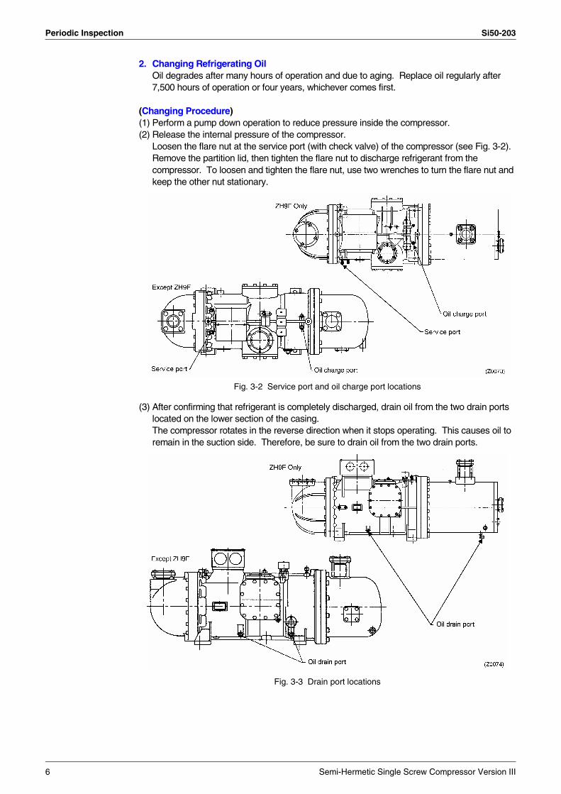
2. Changing Refrigerating OilOil degrades after many hours of operation and due to aging. Replace oil regularly after 7,500 hours of operation or four years, whichever comes first.
(Changing Procedure)(1) Perform a pump down operation to reduce pressure inside the compressor.(2) Release the internal pressure of the compressor.
Loosen the flare nut at the service port (with check valve) of the compressor (see Fig. 3-2). Remove the partition lid, then tighten the flare nut to discharge refrigerant from the compressor. To loosen and tighten the flare nut, use two wrenches to turn the flare nut and keep the other nut stationary.
Fig. 3-2 Service port and oil charge port locations
(3) After confirming that refrigerant is completely discharged, drain oil from the two drain ports located on the lower section of the casing.The compressor rotates in the reverse direction when it stops operating. This causes oil to remain in the suction side. Therefore, be sure to drain oil from the two drain ports.
Fig. 3-3 Drain port locations
6 Semi-Hermetic Single Screw Compressor Version III

Si50-203 Periodic Inspection
(4) Charging oilConnect a vacuum pump to the suction service port (1/4" DCut) on the casing. While evacuating the compressor, add oil from the discharge service port (3/8" DCut). Use SUNISO 4GSD refrigeration oil (possible for use equal product) for refrigerant R22
and DAPHNE FVC68D refrigerant oil for refrigerant R407C and R134a. Add the same amount of new oil as drained because some remains in the refrigerant and
on various parts inside. Drained oil contains refrigerant and appears to be more in volume than actual oil amount. Stir the oil to evaporate the dissolved refrigerant before measuring. Do not add more oil than necessary, since an excessive amount of oil reduces oil separation efficiency and causes system problems. (Oil surface should be visible on the level gauge during equipment operation.)
Take care not to let in air, or dust and other foreign particles remaining on the bottom of the oil container.
When charging oil from a previously opened container, conduct vacuuming of the compressor to remove moisture and air.
3. Inspecting The Gate RotorThis inspection is done to check that no abnormal condition is present due to dust and other foreign particles inside or harsh operating conditions of liquid compression, etc..
(1) Perform a pump down operation to reduce pressure inside the compressor.(2) Release the internal pressure of the compressor.
Loosen the flare nut of the service port (with check valve) of the compressor (see Fig. 3-2). Remove the partition lid, then tighten the flare nut to discharge refrigerant from the compressor.
(3) Remove the side caps from both sides of the compressor. (Fig. 3-4)Since a small amount of oil is still in the compressor, place drain pans under the side caps to receive oil before opening the side caps.
Fig. 3-4 Side cap locations
Semi-Hermetic Single Screw Compressor Version III 7

Periodic Inspection Si50-203
(4) Inspection of the gate rotorVisually check the gate rotor surface for scar, chipping, cracking, etc. Check all gate rotor teeth.
Table 3-1 Gate rotor inspection standards
* When the yellowing is observed on the gate rotor blade, remove gate rotor and check the damage on outside of the screw rotor.If the damage on screw rotor is found, conduct one of the following counter measures.- Repair (deburr, etc.) the damaged part of the screw rotor.- Replace the screw rotor.
(5) Measuring the slit clearanceThe slit clearance is a gap between the gate rotor and casing, and it affects the compressor performance and reliability to a great extent. Therefore, the slit clearance must be set properly (60 to 90 µm).While pressing the periphery of the gate rotor shaft with fingers, insert a thickness gauge into the slit clearance to measure the gaps on both suction and discharge sides. Be careful not to insert the thickness gauge too deep. If the thickness gauge is inserted to deep, it can be caught between the screw rotor and gate rotor and break.(See Fig. 3-7 and 3-8.)
Item Standard Remedy
Cracking No cracking
ReplaceChipping No chipping 3 mm or more long in long side
Scar No scar 1 mm or more deep
Surface yellowing* No yellowing
Fig. 3-5 Inspection of gate rotor chipping Fig. 3-6 Inspection of gate rotor surface
Fig. 3-7 Slit clearance measuring location Fig. 3-8 Measuring slit clearance on suction side
8 Semi-Hermetic Single Screw Compressor Version III
Si50-203 Periodic Inspection
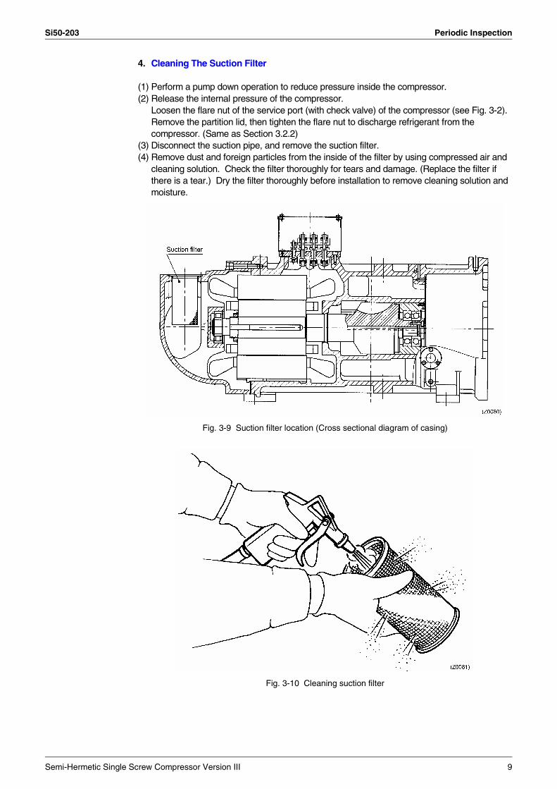
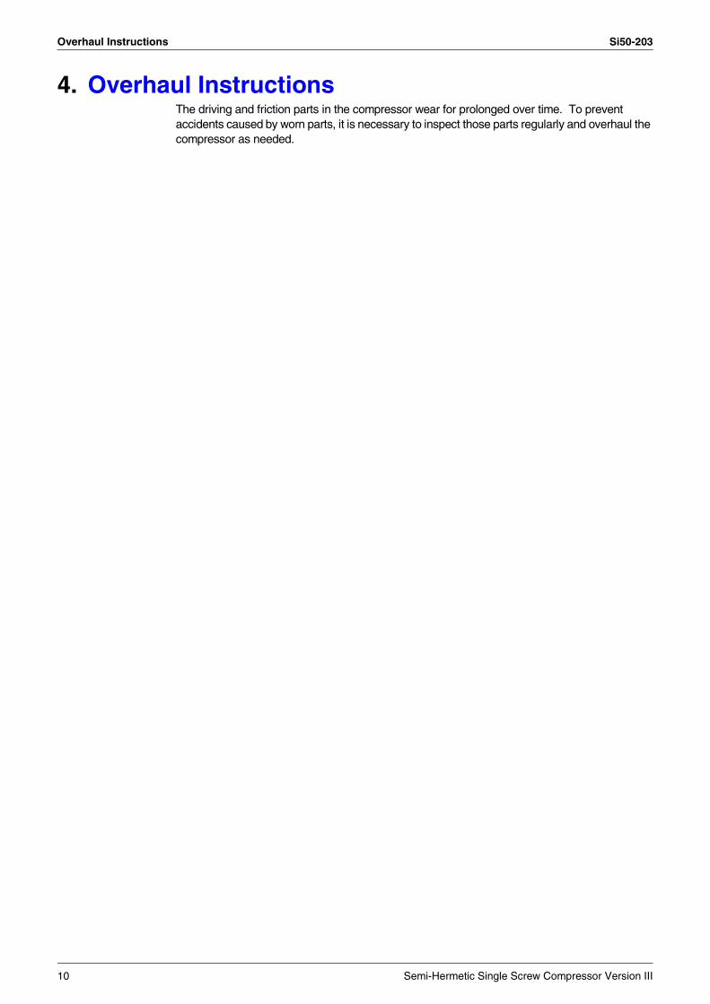
4. Cleaning The Suction Filter
(1) Perform a pump down operation to reduce pressure inside the compressor.(2) Release the internal pressure of the compressor.
Loosen the flare nut of the service port (with check valve) of the compressor (see Fig. 3-2). Remove the partition lid, then tighten the flare nut to discharge refrigerant from the compressor. (Same as Section 3.2.2)
(3) Disconnect the suction pipe, and remove the suction filter.(4) Remove dust and foreign particles from the inside of the filter by using compressed air and
cleaning solution. Check the filter thoroughly for tears and damage. (Replace the filter if there is a tear.) Dry the filter thoroughly before installation to remove cleaning solution and moisture.
Fig. 3-9 Suction filter location (Cross sectional diagram of casing)
Fig. 3-10 Cleaning suction filter
Semi-Hermetic Single Screw Compressor Version III 9
Overhaul Instructions Si50-203
4. Overhaul InstructionsThe driving and friction parts in the compressor wear for prolonged over time. To prevent accidents caused by worn parts, it is necessary to inspect those parts regularly and overhaul the compressor as needed.
10 Semi-Hermetic Single Screw Compressor Version III
Si50-203 Overhaul Instructions
4.1 Disassembly and Inspection1. Draining Oil
Drain oil by referring to Section 3.2.2 "Changing refrigerating oil."
2. Remove The Side Caps (One on Each Side) and The Discharge End Cover. (in case of ZH9F, oil collector)
! Receive remaining oil with a drain pan.! Be sure to mount guide bolts when removing the discharge end cover.! Be careful not to damage the oil filter with the discharge end cover.! Locate the first demister between the discharge end cover and cylinder cover, and remove it.
(Except ZH9F)
Fig. 4-1 Removing side cap Fig. 4-2 Removing discharge end cover
Fig. 4-3 Removing first demister
Semi-Hermetic Single Screw Compressor Version III 11

Overhaul Instructions Si50-203
3. Inspection of The Gate Rotor and Surrounding Parts
(1) Checking the slit clearanceMeasure the slit clearance by referring to Section 3.2.3) "Inspecting The Gate Rotor."
(2) Measuring the backlashMeasure the backlash of the gate rotor and screw rotor. If the measured value exceed the standard value, replace the gate rotor.[Standard value] 0.15 mm or less for all teeth (ZH3, 5) and 0.20mm or less for all teeth (ZH7, 9)
Fig. 4-4 Measurement of gate rotor backlash
4. Disassembling The Gate Rotor and Surrounding Parts
(1) Positioning the screw rotorPosition the screw rotor so that the gate rotor can be removed without damage.
(2) Removing the gate rotor partition lidIn the ZH3F, the gate rotor partition lid is mounted together with the lower bearing holder.
Fig. 4-5 Screw rotor position
Fig. 4-6 Cross sectional diagram of gate rotor
12 Semi-Hermetic Single Screw Compressor Version III
Si50-203 Overhaul Instructions
(3) Removing the gate rotor bearing retainer plateWhile holding the gate rotor with hand, loosen the bolts. Be careful not to lose gate rotor adjusting shims (1) mounted between the gate rotor shaft and retainer plate.Be sure to use the original combination of gate rotor, lower bearing holder, gate rotor adjusting shims and gate rotor adjusting shims (2). (Do not exchange parts between the upper and lower sets).
Fig. 4-7 Removing gate rotor bearing retainer plate
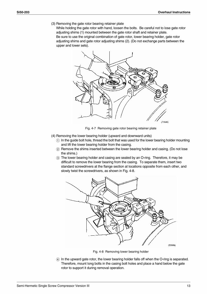
(4) Removing the lower bearing holder (upward and downward units) In the guide bolt hole, thread the bolt that was used for the lower bearing holder mounting
and lift the lower bearing holder from the casing. Remove the shims inserted between the lower bearing holder and casing. (Do not lose
the shims.) The lower bearing holder and casing are sealed by an O-ring. Therefore, it may be
difficult to remove the lower bearing from the casing. To separate them, insert two standard screwdrivers at the flange section at locations opposite from each other, and slowly twist the screwdrivers, as shown in Fig. 4-8.
Fig. 4-8 Removing lower bearing holder
In the upward gate rotor, the lower bearing holder falls off when the O-ring is separated. Therefore, mount long bolts in the casing bolt holes and place a hand below the gate rotor to support it during removal operation.
Semi-Hermetic Single Screw Compressor Version III 13

Overhaul Instructions Si50-203
(5) Turn the gate rotor shaft to remove it from the screw rotor. Be careful not to damage the gate rotor.
5. Removing and Installation of Gate Rotor
(1) Remove C type retaining ring.(2) Remove the gate rotor from the shaft.(3) Apply red check to the gate rotor, and check that the rotor is free of cracks.
If the rotor is found cracked, replace it with a new one.(4) Install the gate rotor on the shaft, and mount the C-type retaining ring.
The gate rotor has front and back sides. Position the gate rotor so that the manufacturing number is visible.
6. Removing The Suction End Cover
(1) Remove all the mounting bolts.(2) Mount guide bolts in two bolt holes on the upper section.
(Be sure to mount guide bolts, since the suction end cover is heavy.)(3) In the guide bolt holes, thread the bolts that were removed previously, then remove the
suction cover from the casing.Locate positioning pins at two locations, and screw them.
Fig. 4-9 Removing suction end cover
14 Semi-Hermetic Single Screw Compressor Version III

Si50-203 Overhaul Instructions
7. Removing The Motor Rotor
(1) Remove the rotor locking plate using a standard screwdriver.(2) Loosen the lock nut. (Use the special tool or jig (1).)(3) As shown in Fig. 4-11 grip rotor fins with pliers, and remove the rotor. Securely support the
rotor so as not to drop the rotor. At removal, be careful not to damage the stator coil end.(4) Remove the motor rotor key from the screw shaft.
Fig. 4-10 Removing rotor locking plate
Fig. 4-11 Removing motor rotor
Semi-Hermetic Single Screw Compressor Version III 15
Overhaul Instructions Si50-203
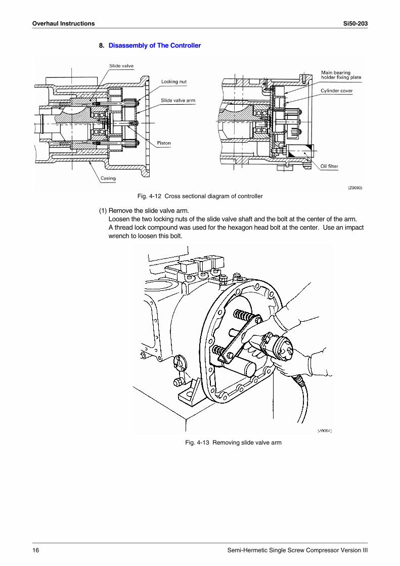
8. Disassembly of The Controller
Fig. 4-12 Cross sectional diagram of controller
(1) Remove the slide valve arm.Loosen the two locking nuts of the slide valve shaft and the bolt at the center of the arm.A thread lock compound was used for the hexagon head bolt at the center. Use an impact wrench to loosen this bolt.
Fig. 4-13 Removing slide valve arm
16 Semi-Hermetic Single Screw Compressor Version III
Si50-203 Overhaul Instructions
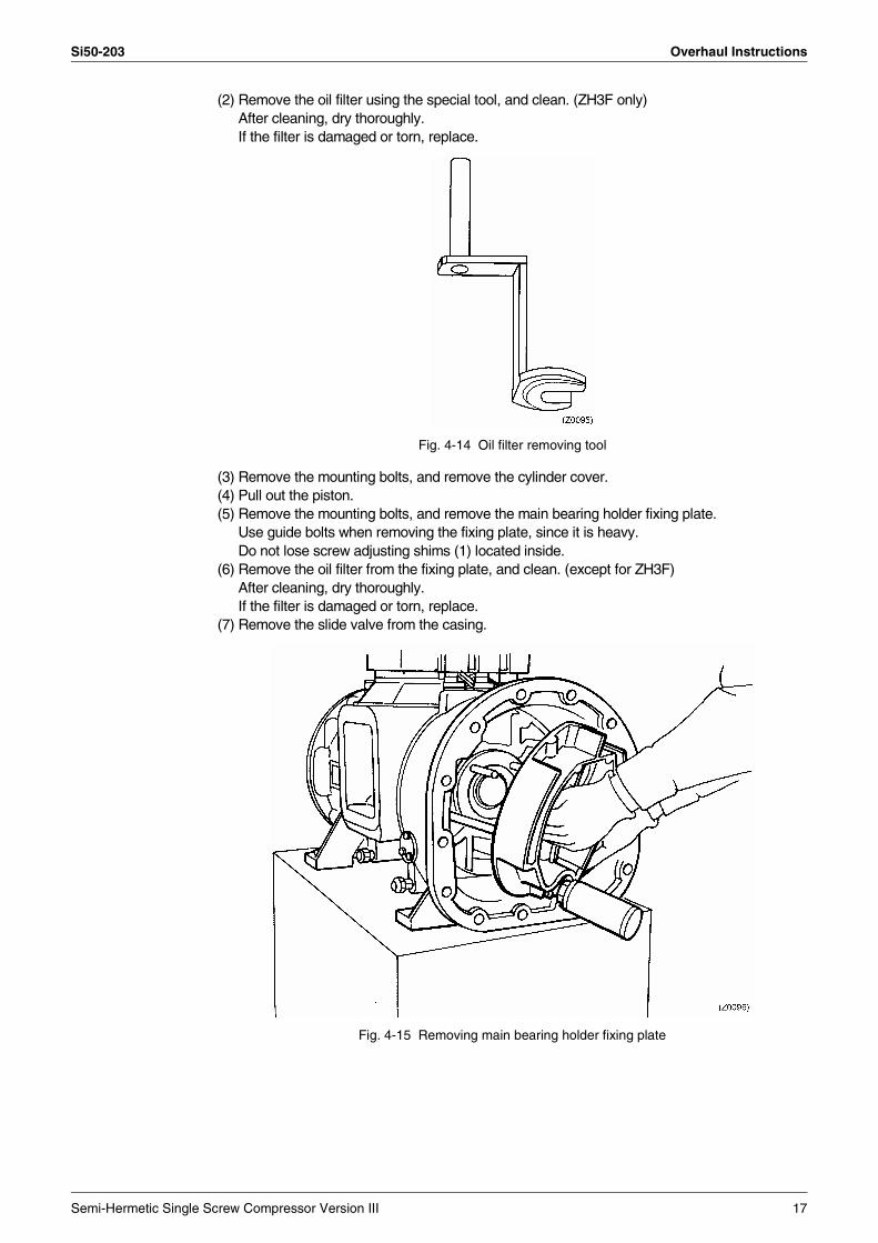
(2) Remove the oil filter using the special tool, and clean. (ZH3F only)After cleaning, dry thoroughly.If the filter is damaged or torn, replace.
Fig. 4-14 Oil filter removing tool
(3) Remove the mounting bolts, and remove the cylinder cover.(4) Pull out the piston.(5) Remove the mounting bolts, and remove the main bearing holder fixing plate.
Use guide bolts when removing the fixing plate, since it is heavy.Do not lose screw adjusting shims (1) located inside.
(6) Remove the oil filter from the fixing plate, and clean. (except for ZH3F)After cleaning, dry thoroughly.If the filter is damaged or torn, replace.
(7) Remove the slide valve from the casing.
Fig. 4-15 Removing main bearing holder fixing plate
Semi-Hermetic Single Screw Compressor Version III 17

Overhaul Instructions Si50-203
9. Removing and Disassembling The Screw Assembly Pulley
(1) Place alignment marks on the casing and main bearing holder.
Fig. 4-16 Placing alignment marks on casing and main bearing holder
(2) Removing the screw shaftPush the screw shaft from the suction side until the bearing holder completely extends from the discharge side. Then pull out the shaft from the discharge side. Insert one hand through the side cap hole and support the shaft to prevent the screw shaft from damaging the casing when the screw rotor section comes out of the casing. Use leather gloves during removal to prevent injuries by the screw and stator.
Fig. 4-17 Removing screw shaft (1)
18 Semi-Hermetic Single Screw Compressor Version III

Si50-203 Overhaul Instructions
Fig. 4-18 Removing screw shaft (2)
(3) Disassembling the screw assemblyRemove the bolts, and remove the screw bearing retainer plate.Remove the main bearing holder from the screw shaft. Do not lose screw rotor adjusting shims (2).
Fig. 4-19 Disassembling screw assembly
Semi-Hermetic Single Screw Compressor Version III 19

Overhaul Instructions Si50-203
4.2 Replacing The BearingUnlike slide bearings, roller bearings have limited service life. They must be replaced regularly.To prevent accidents caused by worn roller bearings, replace all roller bearings during an overhaul.
4.2.1 Removing Bearings1. Main Shaft Bearing
(1) Suction end cover (outer ring of cylindrical roller bearing) Remove the C-type retaining ring. Remove the outer ring of the bearing.
Use an ordinary bearing remover or special jig (2) to remove the outer ring.(2) Screw shaft (inner ring of cylindrical roller bearing)
Remove the C-type retaining ring. Remove the inner ring of the bearing by using a chisel.
Be careful not to scratch the screw shaft. If the screw shaft is accidentally scratched, remove burrs by grinding the irregular surface.
Fig. 4-20 Removing inner ring of screw shaft bearing
(3) Main bearing holder (angular-contact ball bearing, deep groove ball bearing) Removing the beveled C-type retainer ring
The beveled C-type retainer is securely installed in the groove to keep the bearing in place. For easy removal, first pry the end section of the C-type retainer ring toward inside using snap-ring pliers.
Fig. 4-21 Removing C-type retainer ring
20 Semi-Hermetic Single Screw Compressor Version III

Si50-203 Overhaul Instructions
Removing the bearingFrom the opposite side of the end with the C-type retainer ring, remove the outer ring of the bearing by placing a bronze rod and hammering it. Since the outer ring is not pressed in deeply, it can be removed easily.
Fig. 4-22 Removing main bearing holder bearing
2. Gate Rotor Bearings (Angular-Contact Bearing, Deep Groove Ball Bearing)Remove the angular-contact ball bearing and deep groove ball bearing from the lower bearing holder by using a bronze rod and hammer.
Fig. 4-23 Removing lower bearing holder bearing
Semi-Hermetic Single Screw Compressor Version III 21
Overhaul Instructions Si50-203
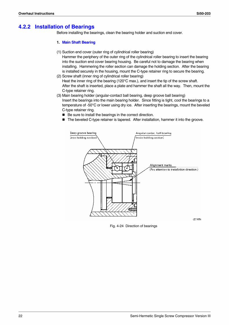
4.2.2 Installation of BearingsBefore installing the bearings, clean the bearing holder and suction end cover.
1. Main Shaft Bearing
(1) Suction end cover (outer ring of cylindrical roller bearing)Hammer the periphery of the outer ring of the cylindrical roller bearing to insert the bearing into the suction end cover bearing housing. Be careful not to damage the bearing when installing. Hammering the roller section can damage the holding section. After the bearing is installed securely in the housing, mount the C-type retainer ring to secure the bearing.
(2) Screw shaft (inner ring of cylindrical roller bearing)Heat the inner ring of the bearing (120°C max.), and insert the tip of the screw shaft.After the shaft is inserted, place a plate and hammer the shaft all the way. Then, mount the C-type retainer ring.
(3) Main bearing holder (angular-contact ball bearing, deep groove ball bearing)Insert the bearings into the main bearing holder. Since fitting is tight, cool the bearings to a temperature of -50°C or lower using dry ice. After inserting the bearings, mount the beveled C-type retainer ring.! Be sure to install the bearings in the correct direction.! The beveled C-type retainer is tapered. After installation, hammer it into the groove.
Fig. 4-24 Direction of bearings
22 Semi-Hermetic Single Screw Compressor Version III

Si50-203 Overhaul Instructions
2. Installing and Adjusting The Gate Rotor Bearings
(1) Installing the bearingsInstall the angular-contact ball bearing and deep groove ball bearing. The bearings must be press-fit, but they do not have to be pressed deeply. Hammer them evenly, and make sure that the bearings rest on the seats. Also, be sure to install the angular-contact ball bearing in the correct direction.
Fig. 4-25 Front and back sides of angular-contact ball bearing
Fig. 4-26 Direction of bearings
(2) Adjusting the preload (temporary assembly)Install the gate rotor shaft in the lower bearing holders mounted with the bearings, and check the preload of the bearings. Insert the gate rotor shaft into the bearings. Install gate rotor shims (2) and the gate rotor bearing retainer plate, and tighten the bolts
to the specified torque. Turn the gate rotor with full force by hand. The gate rotor must rotate smoothly and
should not produce rolling sound.a) When rolling sound is produced
Reduce the thickness of the gate rotor adjusting shims, and check again.b) When gate rotor does not rotate smoothly
Increase the thickness of the gate rotor adjusting shims, and check again. After adjustment, disassembly.
During disassembly, separate the shims, lower bearings and gate rotor shafts according to their installation locations (upward and downward units) so that they can be reinstalled in the original positions.
Semi-Hermetic Single Screw Compressor Version III 23
Overhaul Instructions Si50-203
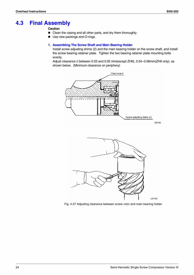
4.3 Final AssemblyCaution! Clean the casing and all other parts, and dry them thoroughly.! Use new packings and O-rings.
1. Assembling The Screw Shaft and Main Bearing HolderInstall screw adjusting shims (2) and the main bearing holder on the screw shaft, and install the screw bearing retainer plate. Tighten the two bearing retainer plate mounting bolts evenly.Adjust clearance δ between 0.03 and 0.05 mm(except ZH9), 0.04~0.06mm(ZH9 only), as shown below. (Minimum clearance on periphery)
Fig. 4-27 Adjusting clearance between screw rotor and main bearing holder
24 Semi-Hermetic Single Screw Compressor Version III

Si50-203 Overhaul Instructions
2. Inserting The Screw ShaftInsert the screw shaft into the casing until the shaft contacts the tapered section of the casing.For this process, wear leather gloves to prevent hand injuries. (Do not use fabric work gloves.)The screw shaft is heavy, and the main bearing holder rotates, making it difficult to hold it. Be careful not to drop the screw shaft during installation.
Fig. 4-28 Inserting screw shaft
3. Installing The Motor Rotor Insert the motor rotor key into the screw shaft from the suction side, and insert the motor
rotor.Insert the motor rotor in the direction shown below.
Fig. 4-29 Motor rotor inserting direction
Tighten the lock nut, and bend the tab on the lock washer to prevent the lock nut from loosening.
Semi-Hermetic Single Screw Compressor Version III 25
Overhaul Instructions Si50-203
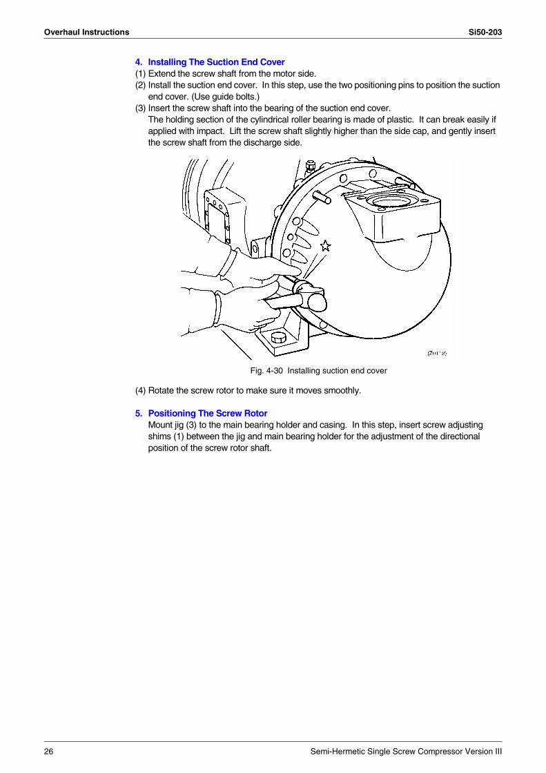
4. Installing The Suction End Cover(1) Extend the screw shaft from the motor side.(2) Install the suction end cover. In this step, use the two positioning pins to position the suction
end cover. (Use guide bolts.)(3) Insert the screw shaft into the bearing of the suction end cover.
The holding section of the cylindrical roller bearing is made of plastic. It can break easily if applied with impact. Lift the screw shaft slightly higher than the side cap, and gently insert the screw shaft from the discharge side.
Fig. 4-30 Installing suction end cover
(4) Rotate the screw rotor to make sure it moves smoothly.
5. Positioning The Screw RotorMount jig (3) to the main bearing holder and casing. In this step, insert screw adjusting shims (1) between the jig and main bearing holder for the adjustment of the directional position of the screw rotor shaft.
26 Semi-Hermetic Single Screw Compressor Version III

Si50-203 Overhaul Instructions
6. Installing The Gate Rotor and Adjusting The Slit Clearance(1) Install the O-rings on the lower bearing holder. (ZH_F : two O-rings)
(ZH_G : three O-rings (two kinds)···Confirm the installing position on spare parts list.)(2) Set the screw rotor in the position indicated in Fig. 4-5, and engage the screw rotor with the
gate rotor.(3) Apply oil on the O-rings of the lower bearing holder, and install the lower bearing holder in
the casing. After the lower bearing holder is inserted to the O-ring section, use the mounting bolt
holes to press the lower bearing holder into the casing.(Use bolts that are 5 to 10 mm longer than the mounting bolts. Using the mounting bolts may damage the threads since they are too short for this process.)
Before the casing and the flange of the lower bearing holder contact, insert shims, and tighten securely.
(4) Install the gate rotor bearing retainer plate.(To prevent the gate rotor from rotating, hold the gate rotor by hand while tightening.)
(5) Measure the slit clearance (gap between the gate rotor and casing) with a clearance gauge.With the clearance gauge hooked on the gate rotor, insert jig (4) into the screw bearing retainer plate. Rotate the screw rotor, and insert the gauge in the slit.1 Standard value: 0.06 to 0.09 mm1 If the measured clearance deviates from the standard value, adjust the thickness of the
gate rotor adjusting shims.(To increase the clearance, add shims.)
(6) Mount the O-ring on the bottom cover of the lower bearing holder, and install the bottom cover of the lower bearing holder.
(7) Install the side cap.
Fig. 4-31 Adjusting slit clearance
Semi-Hermetic Single Screw Compressor Version III 27

Overhaul Instructions Si50-203
7. Installing The Main Bearing Holder Fixing Plate, Assembling The Controller, and Installing The Oil Filter
(1) Insert the slide valve into the casing.1 In the right hole, insert the slide valve with "2" stamped on the end surface.1 Make sure the slide valve operates smoothly.
(2) Mount the oil filter on the fixing plate. (except for ZH3F)(3) Remove jig (2), then install the fixing plate. During this step, insert guide bolts in the main
bearing holder, and place the screw adjusting shims between the main bearing holder and fixing plate.
(4) Insert the piston in the fixing plate
(In case of ZH_F)(5) Place the cylinder cover. Extend the piston until it contacts the cylinder cover, then tighten
the four bolts around the cylinder. (After tightening bolts, make sure the piston moves smoothly.)
Fig. 4-32 Adjusting piston and installing cylinder cover
(6) Tighten the other mounting bolts of the cylinder cover.
(In case of ZH_G)(5), (6) place the cylinder cover. Extend the piston until it contacts the cylinder cover, then tighten the bolts. (After tightening the bolts, make sure the piston moves smoothly.)
(7) Install the oil filter using jig (5). (for ZH3F only)(8) Pull the slide valve forward, then hook the slide valve spring on the slide valve shaft.
(upward and downward units)(9) Install the slide valve arm with the locking nut (slide valve) and bolt (piston).
Use a thread lock compound (Loctite etc.) on the bolt, and use a new locking nut.
8. Installing The Discharge End Cover (In case of ZH9F, Oil collector)Insert the first demister (except ZH9F) in the cylinder cover, and install the discharge end cover.Since the discharge end cover is heavy, be sure to use guide bolts.
28 Semi-Hermetic Single Screw Compressor Version III

Si50-203 Airtightness Test
5. Airtightness TestUsing dry air mixed with refrigerant, pressurize to . Then, use a gas detector (or soap water) to check for leaks. Apply soap water on the side caps and other cover mounting sections to make sure no air bubbles are formed. If air bubbles are formed, release the pressure, then re-tighten the bolts. If the leak does not stop, check the packing seating surfaces and replace the packing.
refrigerant type
R22 2.8MPa(28bar)
R134a 2.0MPa(20bar)
R407c 2.98MPa(29.8bar)
Semi-Hermetic Single Screw Compressor Version III 29

Charging Oil Si50-203
6. Charging OilPart of oil may remain in the refrigerating system. Therefore, charge the same amount of oil removed from the compressor during disassembly. When a new gate rotor is installed, pour about a half of the total oil capacity to the suction side to prevent excessive heating during initial operation.
30 Semi-Hermetic Single Screw Compressor Version III

Si50-203 Caution in Test Operation
7. Caution in Test Operation1) Check to make sure all bolts are tightened.2) Check the wiring for proper connection.3) Conduct inching.
Check the rotating direction using high and low pressure gauges.(If the rotating direction is correct, the low pressure gauge indicates decreasing and the high pressure gauge shows rising pressure.)
Check that no abnormal noise is generated.
Semi-Hermetic Single Screw Compressor Version III 31
Required Tools Si50-203
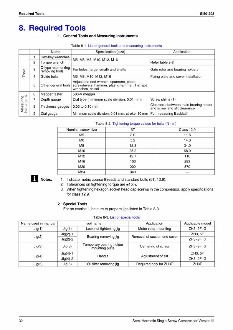
8. Required Tools1. General Tools and Measuring Instruments
Table 8-1 List of general tools and measuring instruments
Table 8-2. Tightening torque values for bolts (N - m)
Notes: 1. Indicate metric coarse threads and standard bolts (5T, 12.9).2. Tolerances on tightening torque are ±15%.3. When tightening hexagon socket head cap screws in the compressor, apply specifications
for class 12.9.
2. Special ToolsFor an overhaul, be sure to prepare jigs listed in Table 8-3.
Table 8-3. List of special tools
Name Specification (size) Application
Too
ls
1 Hex-key wrenchesM5, M6, M8, M10, M12, M16
2 Torque wrench Refer table 8-2
3 C-type retainer ring removing tools For holes (large, small) and shafts Gate rotor and bearing holders
4 Guide bolts M6, M8, M10, M12, M16 Fixing plate and cover installation
5 Other general toolsAdjustable end wrench, spanners, pliers, screwdrivers, hammer, plastic hammer, T-shape wrenches, chisel
Mea
surin
g in
stru
men
ts
6 Megger taster 500-V megger
7 Depth gauge Dial type (minimum scale division: 0.01 mm) Screw shims (1)
8 Thickness gauges 0.03 to 0.10 mm Clearance between main bearing holder and screw and slit clearance
9 Dial gauge Minimum scale division: 0.01 mm, stroke: 10 mm For measuring Backlash
Nominal screw size 5T Class 12.9
M5 3.0 11.6
M6 5.2 14.0
M8 12.3 34.0
M10 25.2 68.0
M12 42.7 118
M16 103 293
M20 202 570
M24 348 —
Name used in manual Tool name Application Applicable model
Jig(1) Jig(1) Lock nut tightening jig Motor rotor mounting ZH3~9F, G
Jig(2)Jig(2)-1
Bearing removing jig Removal of suction end coverZH3, 5F
Jig(2)-2 ZH3~9F, G
Jig(3) Jig(3) Temporary bearing holder mounting plate Centering of screw ZH3~9F, G
Jig(4)Jig(4)-1
Handle Adjustment of slitZH3, 5F
Jig(4)-2 ZH3~9F, G
Jig(5) Jig(5) Oil filter removing jig Required only for ZH3F ZH3F
32 Semi-Hermetic Single Screw Compressor Version III

Si50-203 Required Tools
Jig (1) [Lock Nut Tightening Jig]
Applicablemodel
ZH3_
ZH5F, ZH7F
ZH9F
ZH5G
ZH7G, ZH9G
150
200
250
150
200
7.0
7.6
8.1
7.0
8.1
5
6
7
6
7
76.3
89.1
101.6
76.3
101.6
66
75
92
70
86
10
10
12
10
11
Material
STPG370E65A, sch80
STPG370E80A, sch80
STPG370E90A, sch80
STPG370E65A, sch80
STPG370E90A, sch80
(Z0115)
(through hole)(4 locations)
Semi-Hermetic Single Screw Compressor Version III 33
Required Tools Si50-203
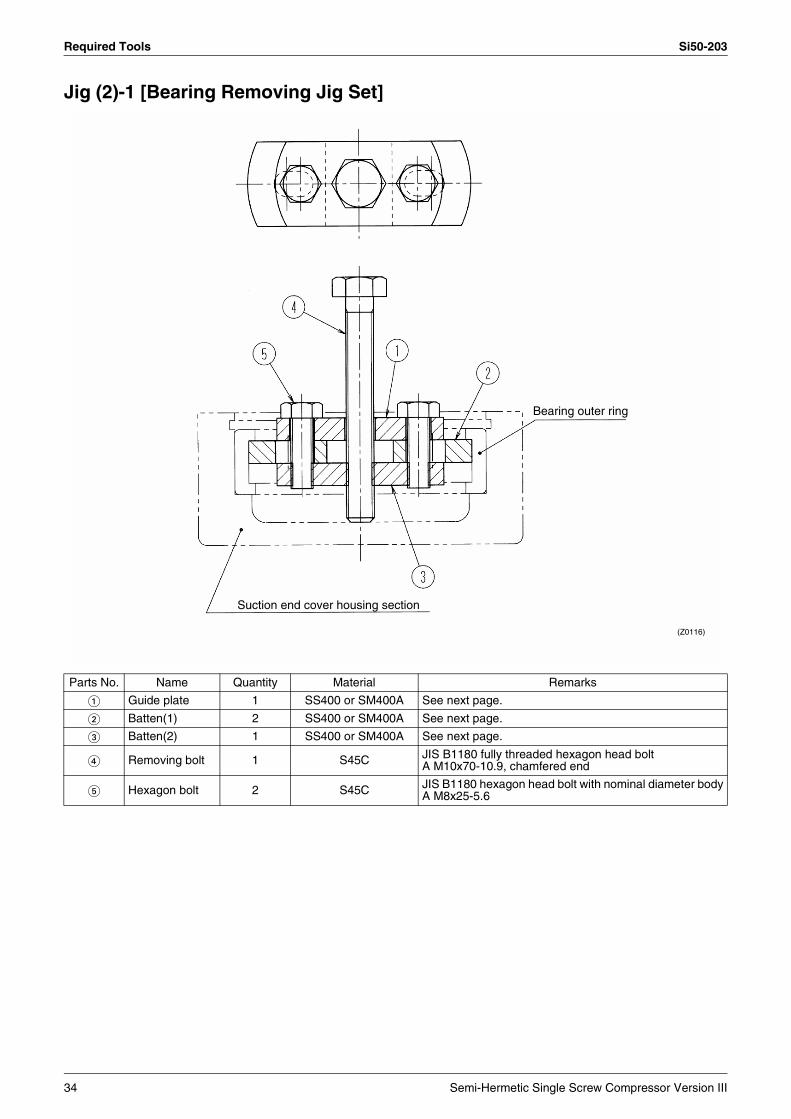
Jig (2)-1 [Bearing Removing Jig Set]
Parts No. Name Quantity Material Remarks
Guide plate 1 SS400 or SM400A See next page.
Batten(1) 2 SS400 or SM400A See next page.
Batten(2) 1 SS400 or SM400A See next page.
Removing bolt 1 S45C JIS B1180 fully threaded hexagon head boltA M10x70-10.9, chamfered end
Hexagon bolt 2 S45C JIS B1180 hexagon head bolt with nominal diameter bodyA M8x25-5.6
(Z0116)
Suction end cover housing section
Bearing outer ring
34 Semi-Hermetic Single Screw Compressor Version III
Si50-203 Required Tools
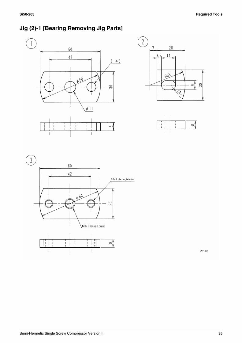
Jig (2)-1 [Bearing Removing Jig Parts]
Semi-Hermetic Single Screw Compressor Version III 35
Required Tools Si50-203
Jig (2)-2 [Bearing Removing Jig Set]
Parts No. Name Quantity Material Remarks
Guide plate 1 SS400 or SM400A See next page.
Batten 1 SS400 or SM400A See next page.
Removing bolt 1 S45C See next page.
Hexagon bolt 2 S45C JIS B1180 hexagon head bolt with nominal diameter bodyA M6x30-5.6
(Z0118)
Holding device
Cylindrical roller bearing
Bearing outer ring
Suction end cover holding section
36 Semi-Hermetic Single Screw Compressor Version III
Si50-203 Required Tools
Jig (2)-2 [Bearing Removing Jig Parts]
(Z0119)
Applicablemodel
ZH3_
ZH5F, ZH7_
ZH5G
ZH9_
25
35
25
35
8
12
8
12
9
13
9
13
54
62
46
67
30
40
30
50
Removing bolt
JIS B 1180 fully threaded hexagon head boltA M8x70-10.9 chamfered end
JIS B 1180 fully threaded hexagon head boltA M12x70-10.9 chamfered end
JIS B 1180 fully threaded hexagon head boltA M8x70-10.9 chamfered end
JIS B 1180 fully threaded hexagon head boltA M12x70-10.9 chamfered end
2-M6 (through hole)
M (through hole)
Semi-Hermetic Single Screw Compressor Version III 37

Required Tools Si50-203
Jig (3) Temporary Bearing Holder Mounting Plate [jig][For ZH3_] Material: SS400
38 Semi-Hermetic Single Screw Compressor Version III
Si50-203 Required Tools
Jig (3) Temporary Bearing Holder Mounting Plate [jig][For ZH5_] Material: SS400
Semi-Hermetic Single Screw Compressor Version III 39
Required Tools Si50-203
Jig (3) Temporary Bearing Holder Mounting Plate [jig][For ZH7_] Material: SS400
40 Semi-Hermetic Single Screw Compressor Version III
Si50-203 Required Tools
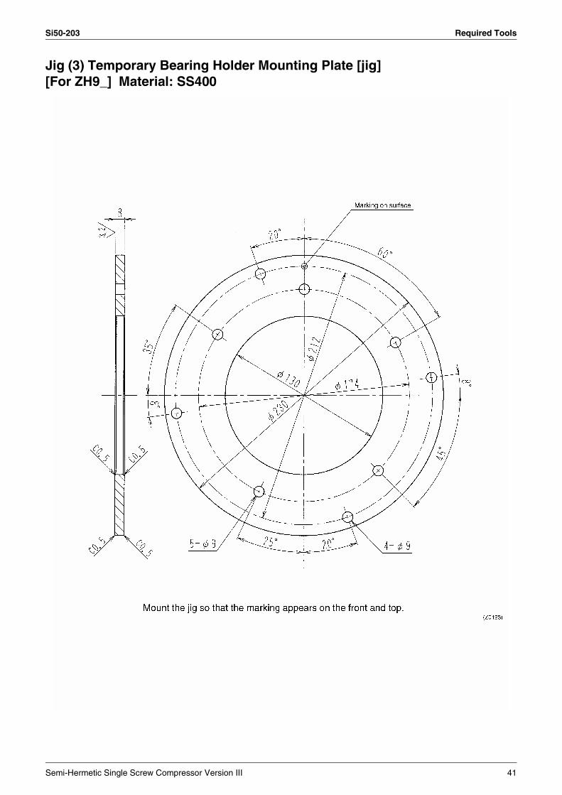
Jig (3) Temporary Bearing Holder Mounting Plate [jig][For ZH9_] Material: SS400
Semi-Hermetic Single Screw Compressor Version III 41
Required Tools Si50-203
Jig (4)-1 [Handle Jig Set]
Parts No.
Name
Handle
Stay (1)
Stay (2)
Disc
Straight pin
Material
STPG370E
SS400 or SM400A
SS400 or SM400A
SS400 or SM400A
S45C
Remarks
20A, sch40(t2. 9)
JIS B1354Class A or equivalent
ZH3_F
300
160
6
20
6
22
ZH5_F
325
185
8
24
8
28
+0.012
0
+0.012
+0.004
+0.015
0
+0.015
+0.006
(Z0124)
42 Semi-Hermetic Single Screw Compressor Version III
Si50-203 Required Tools
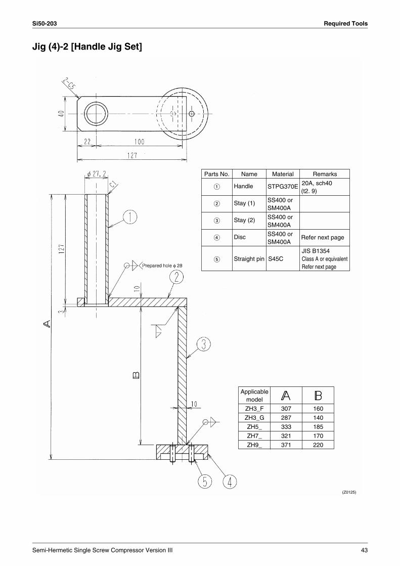
Jig (4)-2 [Handle Jig Set]
(Z0125)
Parts No.
Name
Handle
Stay (1)
Stay (2)
Disc
Straight pin
Material
STPG370E
SS400 or SM400A
SS400 or SM400A
SS400 or SM400A
S45C
Remarks
20A, sch40(t2. 9)
Refer next page
JIS B1354Class A or equivalentRefer next page
Applicablemodel
ZH3_F
ZH3_G
ZH5_
ZH7_
ZH9_
307
287
333
321
371
160
140
185
170
220
Semi-Hermetic Single Screw Compressor Version III 43

Required Tools Si50-203
Jig (4)-2 [Handle Jig Parts]
(Z0126)
Applicablemodel
ZH3_F
ZH3_G
ZH5_
ZH7_
ZH9_
6
6
8
8
8
6
6
8
8
8
20
20
24
24
24
22
26
28
32
36
50.5
50.5
60.5
75.5
80.5
7
7
8
11
11
60
60
70
85
90
+0.012
0
+0.012
0
+0.015
0
+0.015
0
+0.015
0
+0.012
+0.004
+0.012
+0.004
+0.015
+0.006
+0.015
+0.006
+0.015
+0.006
44 Semi-Hermetic Single Screw Compressor Version III
Si50-203 Required Tools
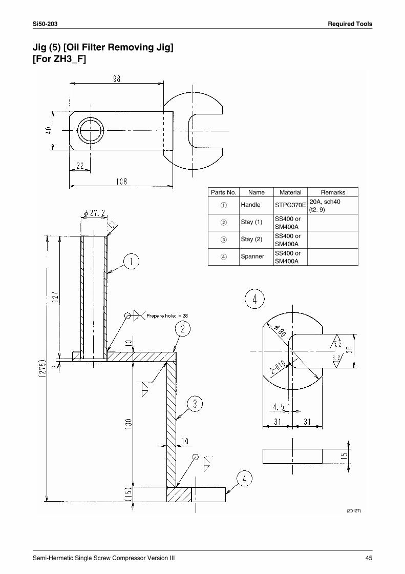
Jig (5) [Oil Filter Removing Jig][For ZH3_F]
Parts No.
Name
Handle
Stay (1)
Stay (2)
Spanner
Material
STPG370E
SS400 or SM400A
SS400 or SM400A
SS400 or SM400A
Remarks
20A, sch40(t2. 9)
(Z0127)
Semi-Hermetic Single Screw Compressor Version III 45

Si50-203
IndexIndexIndexIndex
AAirtightness Test ....................................................29Assembling The Screw Shaft and Main Bearing
Holder .............................................................24
CCaution in Test Operation ......................................31Changing Refrigerating Oil
Changing Procedure ..........................................6Charging Oil ...........................................................30Charging oil ..............................................................7Cleaning The Suction Filter ......................................9
DDisassembling The Gate Rotor and Surrounding
Parts ................................................................12Disassembly and Inspection ..................................11Disassembly of The Controller ...............................16Draining Oil ............................................................11
FFinal Assembly .......................................................24
IInserting The Screw Shaft ......................................25Inspecting The Gate Rotor .......................................7Inspection of The Gate Rotor and Surrounding
Parts ................................................................12Installation of Bearings
Installing and Adjusting The Gate Rotor Bearings ..............................................23
Main Shaft Bearing ..........................................22Installing The Discharge End Cover
(In case of ZH9F, Oil collector) .......................28Installing The Gate Rotor and Adjusting
The Slit Clearance ..........................................27Installing The Main Bearing Holder Fixing Plate,
Assembling The Controller, and Installing The Oil Filter ...................................................28
Installing The Motor Rotor ......................................25Installing The Suction End Cover ...........................26Insulation Resistance of The Motor ..........................5Insulation Resistance Testing
Measurement Standard .....................................5Measuring Procedure ........................................5
OOverhaul ...................................................................3Overhaul Instructions .............................................10
PPeriodic Inspection ...................................................4Periodic Inspection Instructions ...............................5Periodic Inspection Items and Intervals ...................4Positioning The Screw Rotor ..................................26
RRemove The Side Caps (One on Each Side)
and The Discharge End Cover. (in case of ZH9F, oil collector) ....................... 11
Removing and Disassembling The Screw Assembly Pulley ............................................. 18
Removing and Installation of Gate Rotor .............. 14Removing Bearings
Gate Rotor Bearings (Angular-Contact Bearing,Deep Groove Ball Bearing) ................ 21
Main Shaft Bearing ......................................... 20Removing The Motor Rotor ................................... 15Removing The Suction End Cover ........................ 14Replacing The Bearing .......................................... 20Required Tools
List of general tools and measuring instruments ........................................ 32
List of special tools ......................................... 32
SScope of Application ............................................... 2
TTightening torque values for bolts (N - m) ............. 32
Index i

Si50-203
ii Index
Si50-203
Drawings & Flow ChartsDrawings & Flow ChartsDrawings & Flow ChartsDrawings & Flow Charts
AAdjusting clearance between screw rotor and
main bearing holder ........................................24Adjusting piston and installing cylinder cover .........28Adjusting slit clearance ..........................................27
CCleaning suction filter ...............................................9Cross sectional diagram of controller .....................16Cross sectional diagram of gate rotor ....................12
DDirection of bearings ....................................... 22, 23Disassembling screw assembly .............................19Drain port locations ..................................................6
FFront and back sides of angular-contact ball
bearing ............................................................23
IInserting screw shaft ..............................................25Inspection of gate rotor chipping ..............................8Inspection of gate rotor surface ...............................8Installing suction end cover ....................................26
JJig (1) [Lock Nut Tightening Jig] ............................33Jig (2)-1 [Bearing Removing Jig Parts] ..................35Jig (2)-1 [Bearing Removing Jig Set] .....................34Jig (2)-2 [Bearing Removing Jig Parts] ..................37Jig (2)-2 [Bearing Removing Jig Set] .....................36Jig (3) Temporary Bearing Holder Mounting Plate
[jig] [For ZH3_] Material: SS400 ......................38Jig (3) Temporary Bearing Holder Mounting Plate
[jig] [For ZH5_] Material: SS400 ......................39Jig (3) Temporary Bearing Holder Mounting Plate
[jig] [For ZH7_] Material: SS400 ......................40Jig (3) Temporary Bearing Holder Mounting Plate
[jig] [For ZH9_] Material: SS400 ......................41Jig (4)-1 [Handle Jig Set] .......................................42Jig (4)-2 [Handle Jig Parts] ....................................44Jig (4)-2 [Handle Jig Set] .......................................43Jig (5) [Oil Filter Removing Jig] [For ZH3_F] ..........45
MMeasurement of gate rotor backlash .....................12Measuring slit clearance on suction side .................8Motor insulation resistance measuring method ........5Motor rotor inserting direction ................................25
OOil filter removing tool ............................................17
PPlacing alignment marks on casing and main
bearing holder ................................................ 18
RRemoving C-type retainer ring .............................. 20Removing discharge end cover ............................. 11Removing first demister ........................................ 11Removing gate rotor bearing retainer plate ........... 13Removing inner ring of screw shaft bearing .......... 20Removing lower bearing holder ............................ 13Removing lower bearing holder bearing ............... 21Removing main bearing holder bearing ................ 21Removing main bearing holder fixing plate ........... 17Removing motor rotor ........................................... 15Removing rotor locking plate ................................. 15Removing screw shaft (1) ..................................... 18Removing screw shaft (2) ..................................... 19Removing side cap ................................................ 11Removing slide valve arm ..................................... 16Removing suction end cover ................................. 14
SScrew rotor position .............................................. 12Service port and oil charge port locations ............... 6Side cap locations ................................................... 7Slit clearance measuring location ........................... 8Suction filter location (Cross sectional diagram of
casing) ............................................................. 9
Drawings & Flow Charts iii

Si50-203
iv Drawings & Flow Charts

Head office:Umeda Center Bldg., 4-12, Nakazaki-Nishi 2-chome,Kita-ku, Osaka, 530-8323 Japan
Tokyo office:Shinjuku Sumitomo Bldg., 6-1 Nishi-Shinjuku2-chome, Shinjuku-ku, Tokyo, 163-0235 Japan
Zandvoordestraat 300, B-8400 Oostende, Belgium
« The specifications, designs, and information in this manual are subject to change without notice.
Printed in Japan 02/2003 AK
Semi-Hermetic Single Screw Compressor Version
For Overhaul and Inspection
[Applied Models]
ZH(C)3LSF ZH3LMF ZH(C)3LTGZH(C)5MLF ZH5SLF ZH(C)3WLGZH(C), (A)5LLF ZH5LMF ZH(C), (A)5LMGZH(C), (A)7SLF ZHA7MLF ZH(C), (A)5WLGZH(C)7LLF ZHA7MSGZH(C)7LSGZH(C), (A)9SLF ZH(C), (A)7WSGZH(C), (A)9LLF ZH(C), (A)9LSG ZH(C), (A)9WSG
Si50-203