for p g - ministry of environment, forest and climate … breaking...table of contents tgm for ship...
TRANSCRIPT
FOR
P G
Prepared for
Government of India

Project Coordination Ministry of Environment & Forests
Dr. Nalini Bhat Advisor, Ministry of Environment and Forests
Dr. T. Chandni Director, Ministry of Environment and Forests
Core Project Coordination Team IL&FS Environment
Mr. Mahesh Babu CEO
Mr. N. Sateesh Babu Vice President & Project Director
Ms. Chaitanya Vangeti Assistant Manager - Technical
Ms. Suman Benedicta Thomas Technical Writer
Resource Person Mr. R. K. Gupta
Former Executive Director, SAIL
Expert Core & Peer Committee Chairman Dr. V. Rajagopalan, IAS
Additional Secretary, Ministry of Chemicals & Fertilizers
Core Members Dr. R. K. Garg Former Chairman, EIA Committee, Ministry of Environment and Forests
Mr. Paritosh C. Tyagi Former Chairman, Central Pollution Control Board
Prof. S.P. Gautam Chairman, Central Pollution Control Board
Dr. Tapan Chakraborti Director, National Environmental Engineering Research Institute
Mr. K. P. Nyati Former Head, Environmental Policy, Confederation of Indian Industry
Dr. G.K. Pandey Former Advisor, Ministry of Environment and Forests
Dr. Nalini Bhat Advisor, Ministry of Environment and Forests
Dr. G.V. Subramaniam Advisor, Ministry of Environment and Forests
Dr. B. Sengupta Former Member Secretary, Central Pollution Control Board
Dr. R. C. Trivedi Former Scientist, Central Pollution Control Board
Peer Member Mr. K. D. Choudhury Former GM (Environment), MECON
Member Convener Mr. N. Sateesh Babu Project Director

Table of Contents
TGM for Ship Breaking Yard August 2010 i
TABLE OF CONTENTS
1. INTRODUCTION TO THE TECHNICAL EIA GUIDANCE MANUALS PROJECT ...... 1-1
1.1 Purpose ................................................................................................................................ 1-2
1.2 Project Implementation ....................................................................................................... 1-4
1.3 Additional Information ........................................................................................................ 1-4
2. CONCEPTUAL FACETS OF EIA ............................................................................................ 2-1
2.1 Environment in EIA Context ............................................................................................... 2-1
2.2 Pollution Control Strategies ................................................................................................ 2-2
2.3 Tools for Preventive Environmental Management .............................................................. 2-2
2.3.1 Tools for assessment and analysis ......................................................................... 2-3
2.3.2 Tools for action ...................................................................................................... 2-5
2.3.3 Tools for communication ....................................................................................... 2-9
2.4 Objectives of EIA .............................................................................................................. 2-10
2.5 Types of EIA ..................................................................................................................... 2-10
2.6 Basic EIA Principles ......................................................................................................... 2-11
2.7 Project Cycle ..................................................................................................................... 2-12
2.8 Environmental Impacts ..................................................................................................... 2-13
2.8.1 Direct impacts ...................................................................................................... 2-14
2.8.2 Indirect impacts ................................................................................................... 2-14
2.8.3 Cumulative impacts ............................................................................................. 2-15
2.8.4 Induced impacts ................................................................................................... 2-15
2.9 Significance of impacts ..................................................................................................... 2-15
2.9.1 Criteria/methodology to determine the significance of identified impacts .......... 2-16
3. ABOUT SHIP BREAKING YARD INCLUDING BEST PRACTICES AND
POLLUTION CONTROL TECHNOLOGIES ......................................................................... 3-1
3.1 Introduction ......................................................................................................................... 3-1
3.1.1 Ship breaking in India ............................................................................................ 3-4
3.1.2 Process of ship procurement for scrapping in India .............................................. 3-4
3.1.3 Ship breaking methods .......................................................................................... 3-6
3.2 Material recovery and waste generation factors .................................................................. 3-8
3.2.1 Hazardous material in ships ................................................................................... 3-9
3.2.2 Specific wastes of concern from ship breaking process and their
management ......................................................................................................... 3-10
3.3 Infrastructure and Other Requirements for the Ship Breaking Yard ................................. 3-34
3.3.1 Size of the individual plot in the ship breaking yard ........................................... 3-36
3.3.2 Risk assessment ................................................................................................... 3-37
3.3.3 Water supply ........................................................................................................ 3-38
3.3.4 Sewage ................................................................................................................. 3-38
3.3.5 Stormwater drainage system ................................................................................ 3-38
3.3.6 Bilge and ballast water collection and treatment ................................................. 3-38
3.3.7 Municipal solid waste collection and treatment .................................................. 3-39
3.3.8 Hazardous waste disposal facility ........................................................................ 3-39
Table of Contents
TGM for Ship Breaking Yard August 2010 ii
3.3.9 Oily waste/residues collection, treatment and disposal ....................................... 3-40
3.3.10 Truck parking facility 3-40
3.3.11 Community development infrastructure .............................................................. 3-40
3.3.12 Hospital management and medical infrastructure ............................................... 3-41
3.3.13 Greenbelt development and water harvesting ...................................................... 3-41
3.3.14 Safety health and environmental management cell operations ............................ 3-41
3.3.15 Commercial centers ......................................................................................... 3-42
3.3.16 Vehicles ......................................................................................... 3-42
3.3.17 Roads ......................................................................................... 3-42
3.3.18 Firefighting infrastructure .................................................................................... 3-42
3.3.19 Training infrastructure development and organizing capacity building and
certification courses ......................................................................................... 3-43
3.4 Summary of Applicable National Regulations .................................................................. 3-43
3.4.1 General standards for discharge of environmental pollutants ............................. 3-43
3.4.2 Specific requirements .......................................................................................... 3-44
3.4.3 Pending & proposed regulatory requirements ..................................................... 3-46
4. OPERATIONAL ASPECTS OF EIA ........................................................................................ 4-1
4.1 Coverage of Ship Breaking Yards under the Purview of Notification ................................ 4-1
4.1.1 Application for prior environmental clearance ...................................................... 4-3
4.2 Scoping for EIA Studies ...................................................................................................... 4-3
4.2.1 Pre-feasibility report .............................................................................................. 4-4
4.2.2 Guidance for Filling Information in Form 1 .......................................................... 4-6
4.2.3 Identification of appropriate valued environmental components .......................... 4-6
4.2.4 Methods for identification of impacts .................................................................... 4-6
4.2.5 Testing the significance of impacts ..................................................................... 4-12
4.2.6 Terms of reference for EIA studies ..................................................................... 4-12
4.3 Environmental Impact Assessment ................................................................................... 4-16
4.3.1 EIA team .............................................................................................................. 4-17
4.3.2 Baseline quality of the environment .................................................................... 4-17
4.3.3 Impact prediction tools ........................................................................................ 4-20
4.3.4 Significance of the impacts .................................................................................. 4-20
4.4 Social Impact Assessment ................................................................................................. 4-21
4.5 Risk Assessment and Disaster Management Plan ............................................................. 4-24
4.5.1 Risk assessment ................................................................................................... 4-24
4.5.2 Disaster management plan ................................................................................... 4-29
4.6 Mitigation Measures .......................................................................................................... 4-33
4.6.1 Important considerations for mitigation methods ................................................ 4-33
4.6.2 Hierarchy of elements of mitigation plan ............................................................ 4-34
4.6.3 Typical mitigation measures ................................................................................ 4-35
4.7 Environmental Management Plan ..................................................................................... 4-38
4.8 Reporting ........................................................................................................................... 4-39
4.9 Public Consultation ........................................................................................................... 4-41
4.10 Appraisal ........................................................................................................................... 4-44
4.11 Decision-making ............................................................................................................... 4-46
4.12 Post-clearance Monitoring Protocol .................................................................................. 4-47
5. STAKEHOLDERS’ ROLES AND RESPONSIBILITIES ...................................................... 5-1

Table of Contents
TGM for Ship Breaking Yard August 2010 iii
5.1 EAC ..................................................................................................................................... 5-3
LIST OF FIGURES
Figure 2-1: Inclusive Components of Sustainable Development ............................................................ 2-1
Figure 2-2: Types of Impacts ................................................................................................................ 2-14
Figure 2-3: Cumulative Impact ............................................................................................................. 2-15
Figure 3-1: Ship Procurement Process for Scrapping in India ................................................................ 3-5
Figure 3-2: Ship Scrapping Decision Process ......................................................................................... 3-6
Figure 3-3: Conceptual Model Ship Breaking Unit in a Yard .............................................................. 3-37
Figure 3-4: Bilge and Ballast Water Treatment Scheme ...................................................................... 3-39
Figure 4-1: Prior Environmental Clearance Process for Activities Falling Under Category A .............. 4-2
Figure 4-2: Approach for EIA Studies .................................................................................................. 4-16
Figure 4-3: Risk Assessment: Conceptual Framework ......................................................................... 4-24
Figure 4-4: Comprehensive Risk Assessment at a Glance .................................................................... 4-26
Figure 4-5: Hierarchy of Elements of Mitigation Plan ......................................................................... 4-34
LIST OF TABLES
Table 3-1: Broad Comparison of Three Ship Breaking Methods ........................................................... 3-6
Table 3-2: Prevailing Scrap Recovery /Waste Generation Factors from Ship breaking ........................ 3-8
Table 3-3: Ship category-specific Indicative yield of materials (in % of LSW) ..................................... 3-9
Table 3-4: Break-up of wastes from Ship breaking Activities at Alang Yard ........................................ 3-9
Table 3-5: Zone-wise Recurrence of Predominant Hazards ................................................................. 3-37
Table 3-6: Treated Effluent Standards as per CPCB ............................................................................ 3-44
Table 4-1: Advantages and Disadvantages of Impact Identification Methods ....................................... 4-7
Table of Contents
TGM for Ship Breaking Yard August 2010 iv
Table 4-2: Matrix of Impacts .................................................................................................................. 4-9
Table 4-3: List of Important Physical Environment Components ........................................................ 4-18
Table 4-4: Choice of Methods for Impact Prediction: Risk Assessment .............................................. 4-25
Table 4-5: Typical Mitigation Measures ............................................................................................... 4-36
Table 4-6: Rules to be followed for Handling Waste ........................................................................... 4-38
Table 4-7: Structure of EIA Report ....................................................................................................... 4-39
Table 5-1: Roles and Responsibilities of Stakeholders Involved in Prior Environmental
Clearance ............................................................................................................................. 5-1
Table 5-2: Organization-specific Functions ............................................................................................ 5-2
Table 5-3: EAC: Eligibility Criteria for Chairperson/ Members / Secretary .......................................... 5-5
LIST OF ANNEXURES
Annexure I
Elements of Ship Breaking Process
Annexure II
List of Hazardous Materials and Substances that are Applicable to Ship Breaking
Annexure III
Main Items of Ships and Substances of Concern with Disposal Options
Annexure IV
Preventive Measures for Environmental Elements of Concern
Annexure V
General Standards for Discharge of Environmental Pollutants as per CPCB
Table of Contents
TGM for Ship Breaking Yard v August 2010
Annexure VI
Densities of Different Types of Waste
Annexure VII
Codification of National & International laws/Guidelines relating to Ship Breaking Activities (SCMC)
A Compilation of Legal Instruments (CPCB)
Ship Breaking Activities and Enforcing Agencies (SCMC)
Annexure VIII
Form 1 (Application Form for Obtaining EIA Clearance)
Annexure IX
Pre-feasibility Report: Points for Possible Coverage
Annexure X
Types of Monitoring and Network Design Considerations
Annexure XI
Guidance for Assessment of Baseline Components and Attributes
Annexure XII
Sources of Secondary Data
Annexure XIII
Impact Prediction Tools
Annexure XIV
Environmental, Health and Safety Measures
Annexure XV
Composition of EAC
Annexure XVI
Best Practices & Latest Technologies available and reference
Table of Contents
TGM for Ship Breaking Yard August 2010 vi
ACRONYMS
AAQ Ambient Air Quality
ACM Asbestos-containing Material
ACWM Asbestos Containing Waste Material
BIS Bureau of Indian Standards
BOT Build Operate Transfer
CCA Conventional Cost Accounting
CER Corporate Environmental Reports
CFE Consent for Establishment
CO Carbon monoxide
CO2 Carbon Dioxide
CP Cleaner Production
CPCB Central Pollution Control Board
CRZ Coastal Regulatory Zone
dB Decibels
DGFASLI Directorate General Factory Advice Service and Labour Institutes
DO Dissolved Oxygen
DMP Disaster Management Plan
dwt Dead Weight Tonnage
EAC Expert Appraisal Committee
EBM Environmental Baseline Monitoring
EcE Economic-cum-Environmental
ECI Environmental Condition Indicators
EIA Environmental Impact Assessment
EPI Environmental Performance Indicators
EMS Environmental Management System
ETP Effluent Treatment Plant
f/cc fibre per cubic centimetre
FCA Full Cost assessment
GMB Gujarat Maritime Board
GIS Geographical Information Systems
GoI Government of India
HAP Hazardous Air Pollutant
HEPA High Efficiency Particulate Air
HTL High Tide Line
IL&FS Infrastructure Leasing and Financial Services
IMO International Maritime Organization
LCA Life Cycle Analysis
Table of Contents
TGM for Ship Breaking Yard August 2010 vii
LDAR Leak Detection and Repair
LDT Light Displacement Ton
LSW Light Ship Weight
M metre
MoEF Ministry of Environment & Forests
MT Metric Tonne
NOx Oxides of Nitrogen
NPE Negative Pressure Enclosure
OHS Occupational Health and Safety
OSHA Occupational Safety and Health Administration
PACM Presumed Asbestos Containing Material
Pb3O4 lead tetraoxide
PAH Polycyclic Aromatic Hydrocarbons
PCB Polychlorinated biphenyls
PCC Pollution Control Committee
PELs Permissible Exposure Limits
PFCs Perfluorocarbons
PPE Personal Protection Equipment
ppm Parts per Million
QRA Quantitative Risk Assessment
RACM Regulated Asbestos Containing Material
R&D Research and Development
R&R Resettlement and Rehabilitation
RSPM Respirable Suspended Particulate Matter
SEAC State Level Expert Appraisal Committee
SEIAA State Level Environment Impact Assessment Authority
SPV Special Purpose Vessels
SEZ Special Economic Zone
TCA Total Cost Assessment
TDS Total Dissolved Solids
TEQM Total Environmental Quality Movement
TGM Technical EIA Guidance Manuals
TSDF Treatment Storage Disposal Facility
TWA Time-weighted Average
UT Union Territory
VOC Volatile Organic Compound
VEC Valued Environmental Component
WBCSD World Business Council on Sustainable Development


q{Rrc T}aTJAIRAM RAMESH
qrwr dff fada uenr)qqFRuf Eq aa
e{rta T|*Frrag Rd-r r oooa
MIMSTER OF STATE (INDEPENDENT CHARGE)ENVIRONMENT & FORESTS
GOVERNMENT OF INDIANEW DELHI . 110 OO3
22"d December 2010
FOREWORD
The Ministry of Environrnent & Forests (MOEF) introduced the Envirorunentar ImpactAssessment (EIA) Notificati on 2006 on 14tr, Septernber 2006, which not only reensineered theenhre environment clearance (EC) process "peiified
under the EIA Notifica'tion i6q+, u,r, ut.ointroduced a number of new developmentaf sectors which would require prior environmentalclearance The EIA Notification 2006 has notified a list of 39 developrnentai sectors which havebeen further categorised as A or B based on their capacity and iikely environmental rmpacts.ised as B1 and 82. The EIA Notification 2006 hasrping and appraisal and for the setting up of(EIAA) at the Cenhal level and State LeveiEIAAs) to grant environmental clearances at thery of Environment & Forests is the Environmentlevel and 25 State Level Environment ImDactset up in the various States/UTs. fne
-nm
Committee (EAC) at the Centre and state ,:*l*3,.Tii;1#:lkhtJlrtr.;":istar/ur Level for appraisal of Category A or B projects respectively and to recommendgrant/rejection of environmental clearance to each pioject/activities fulirrg,rr.d". th" rrurro,r.sectors to the EIAA/SEIAAs respectively.
^ Although the process of obtaining environmentar clearance consisting of screemng,scoping and Appraisal and for undertaking pubric consultation incruding "th"
p-"u* ofconduct of Public Hearing has been elaborateJunder the EIA Notification 2006", the Niotijicationitself provides for bringing out guidelines from time to time on the EIA Notification 2006 andthe EC process with a view to rrringing_ clarity orr the EC process for expediting environmentarclearance. This need was further ieir{orced' after the constitution of sEIAAs and sEACs invarious States, who were assigned the task for the first time and for addressing the concerns of:3191.*3dr" of the quality of appraisal and in reducing inconsisiencies betweenSEACs/SEIAAs in granting ECs for simiiar projects in different States.
The Technical Guidance Manuar of "ship Breaking yards" sector describes types ofprocess and pollution control technologies, operatonai aspects of EIA with moder roR of thatsector, technological options with cleaner production ind waste minimization techniques,monitodng of environmental quality, post clearance monitoring protocol, related regulations,and procedure of obtaining EC if rinked to other clearances for e.f., cnz,
"i".
-- --- --""
F&aql

The ship recycling industry offers thousands of jobs for migrant workers. However, thelack of environrnental and safety measures can lead to high accident rates, heath risks, andpollution of coastal areas. Moreover, hazardous materials like asbestos, polychlorinatedbiphenyls (PCBs), hibutyl tin, and large quantities of oils and oil sludge pose further risks.
To keep pace with changing technologies and needs of sustainable developmen! themanual would require regular updating in the future. The manual will be available on theMoEF website and we would appreciate receiving responses from stakeholders for furtherimprovements.
I congratulate the entire tearn of IL&FS Ecosmart Ltd., experts from the sector who wereinvolved in the preparation of the Manuals, Chairman and members of the Core and PeerCommittees of various sectors and various Resource Persons whose inouts were indeedvaluable in the preparation and finalization of the Manuals.
(Jaram Ka sh)
Introduction
TGM for Ship Breaking Yard August 2010 1-1
1. INTRODUCTION TO THE TECHNICAL EIA
GUIDANCE MANUALS PROJECT
Environmental Impact Assessment (EIA) is a process of identifying, predicting,
evaluating and mitigating the biophysical, social, and other relevant effects of
development proposals prior to major decisions being taken and commitments made.
These studies integrate the environmental concerns of developmental activities into the
process of decision-making.
EIA has emerged as one of the successful policy innovations of the 20th Century to
ensure sustained development. Today, EIA is formalized as a regulatory tool in more
than 100 countries for effective integration of environmental concerns with the economic
development process. The EIA process in India was made mandatory and was also given
a legislative status through a Notification issued by the Ministry of Environment and
Forests (MoEF) in January 1994. The Notification, however, covered only a few selected
industrial developmental activities. While there are subsequent amendments, the
Notification issued on September 14, 2006 supersedes all the earlier Notifications, and
has brought out structural changes in the clearance mechanism.
The basic tenets of this EIA Notification could be summarized into following:
Pollution potential as the basis for prior environmental clearance instead of
investment criteria; and
Decentralization of powers to the State/Union Territory (UT) level Authorities for
certain developmental activities to make the prior environmental clearance process
quicker, transparent and effective.
Devolution of the power to grant clearances at the state-level for certain categories of the
developmental activities / projects is a step forward to fulfill the basic tenets of the re-
engineering i.e., quicker, transparent and effective process but many issues impede/hinder
its functional efficiency. These issues could be in technical and operational as listed
below:
Technical Issues
Ensuring level playing ground to avoid arbitrariness in the decision-making process
Classification of projects which do not require public hearing and detailed EIA
(Category B2)
Variations in drawing Terms of Reference (ToR) for EIA studies for a given
developmental activity across the States/UTs
Varying developmental-activity-specific expertise requirement for EIA studies and
their appraisal
Availability of adequate sectoral experts and variations in competency levels
Inadequate data verification, cross checking tools and supporting institutional
framework
Meeting time targets without compromising with the quality of assessments / reviews

Introduction
TGM for Ship Breaking Yard August 2010 1-2
Varying knowledge and skill levels of regulators, consultants and experts
Newly added developmental activities for prior environmental clearance, etc.
Operational Issues
State/UT level EIA Authorities (SEIAA/UTEIAA) are formulated for the first time
and many are functioning
Varying roles and responsibilities of involved organizations
Varying supporting institutional strengths across the States/UTs
Varying manpower availability, etc.
1.1 Purpose
The purpose of developing the sector-specific Technical EIA Guidance Manual (TGM) is
to provide clear and concise information on EIA to all the stakeholders i.e., the project
proponent, the consultant, the reviewer, and the public. The TGMs are organized to cover
following:
Chapter 1 (Introduction): This chapter provides a brief introduction on the EIA, basic
tenets of EIA Notification, technical & operational issues in the process of clearance,
purpose of the TGMs, project implementation process and additional information.
Chapter 2 (Conceptual facets of an EIA): Provides an overall understanding to the
conceptual aspects of control of pollution and EIA for the developmental projects. This
basic understanding would set the readers at same level of understanding for proper
interpretations and boundaries for identifying the environmental interactions of the
developmental projects and their significance for taking measures of mitigation. This
chapter covers the discussion on environment in EIA context i.e sustainable development,
pollution control strategies, preventive environmental management tools, Objectives of
EIA, types and basic principles of EIA, project cycle for ship breaking yard,
understanding on type of environmental impacts and the criteria for the significance
analysis.
Chapter 3 (Ship breaking yard): The purpose of this chapter is to provide the reader
precise information on all the relevant aspects of the industry, which is essential to realize
the likely interaction of such developmental activities on the receiving environment.
Besides, this Chapter gives a holistic understanding on the sources of pollution and the
opportunities of the source control.
The specific coverage which provides precise information on the industry include (i)
Introduction - Ship breaking in India, Process of ship procurement for scrapping in India,
Ship breaking methods, (ii) Material recovery and waste generation factors - Hazardous
material in ships, Specific wastes of concern from ship breaking process and their
management, (iii) Infrastructure and Other Requirements for the Ship Breaking Yard -
Size of the individual plot in the ship breaking yard, Risk assessment, Water supply,
Sewage, Storm water drainage system, Bilge and ballast water collection and treatment,
Municipal solid waste collection and treatment, Hazardous waste disposal facility, Oily
waste/residues collection, treatment and disposal, Truck parking facility, Community
development infrastructure, Hospital management and medical infrastructure, Greenbelt
development and water harvesting, Safety health and environmental management cell
operations, Commercial centers, Vehicles, Roads, Fire fighting infrastructure, Training

Introduction
TGM for Ship Breaking Yard August 2010 1-3
infrastructure development and organizing capacity building and certification courses ,
and (iv) Summary of Applicable National Regulations - Specific requirements, general
standards for discharge of environmental pollutants, Pending & proposed regulatory
requirements.
Chapter 4 (Operational aspects): The purpose of this chapter is to facilitate the
stakeholders to extend clear guidance on coverage of legislative requirements, sequence
of procedures for obtaining the EIA clearance and each step-wise provisions and
considerations.
The coverage of the Chapter include provisions in the EIA Notification regarding Ship
breaking yard, scoping (pre-feasibility report, guidance for filling form 1, identification of
valued environmental components, identification of impacts, etc.), arriving at terms of
reference for EIA studies, impact assessment studies (EIA team, assessment of baseline
quality of environment, impact prediction tools, significance of impacts), social impact
assessment, risk assessment considerations, typical mitigation measures, designing
considerations for environmental management plan, structure of EIA report for
incorporation of study findings, process of public consultation, project appraisal, decision
making process and post-clearance monitoring protocol.
Chapter 5 (Roles and responsibilities of various organizations involved in the
process of prior environmental clearance): The purpose of this Chapter is to brief the
stakeholders on the institutional mechanism and roles & responsibilities of the
stakeholders involved in the process of prior environmental clearance. The Coverage of
the Chapter include (i) roles and responsibilities of the stakeholders, (ii) organization
specific functions, (iii) constitution, composition and decision making process of EAC
and (iv) EAC and (v) other conditions which may be considered
For any given industry, each topic listed above could alone be the subject of a lengthy
volume. However, in order to produce a manageable document, this project focuses on
providing summary information for each topic. This format provides the reader with a
synopsis of each issue. Text within each section was researched from many sources, and
was condensed from more detailed sources pertaining to specific topics.
The contents of the document are designed with a vire to facilitate addressing of relevant
technical and operational issues as mentioned in the earlier section. Besides, facilitates
various stakeholders involved in the EIA clearance process i.e.,
Project proponents will be fully aware of the procedures, common ToR for EIA
studies, timelines, monitoring needs etc., in order to plan the projects / studies,
appropriately.
The consultants across India will gain similar understanding about a given sector, and
also the procedure for EIA studies, so that the quality of the EIA reports gets
improved and streamlined.
Reviewers across the States / UTs will have the same understanding about an
industrial sector and would be able to draw a benchmark in establishing the
significant impacts for the purpose of prescribing the ToR for EIA studies and also in
the process of review and appraisal.
Public who are concerned about new or expansion projects, can use this manual to
get a basic idea about the manufacturing/production details, rejects/wastes from the
operations, choice of cleaner/control technologies, regulatory requirements, likely
environmental and social concerns, mitigation measures, etc., in order to seek
Introduction
TGM for Ship Breaking Yard August 2010 1-4
clarifications appropriately in the process of public consultation. The procedural
clarity in the document will further strengthen them to understand the stages involved
in clearance and roles & responsibilities of various organizations.
In addition, these manuals would substantially ease the pressure on reviewers at the
scoping stage and would bring in functional efficiency at the central and state levels.
1.2 Project Implementation
The Ministry of Environment & Forests (MoEF), Government of India took up the task of
developing sector-specific TGMs for all the developmental activities listed in the re-
engineered EIA Notification. Infrastructure Leasing and Financial Services Ecosmart
Limited (IL&FS Ecosmart), has been entrusted with the task of developing these manuals
for 27 industrial and related sectors. Ship Breaking Yard is one of these sectors, for
which this manual is prepared.
The ability to design EIA studies for specific industries depends on the knowledge of
several interrelated topics. Therefore, it requires expert inputs from multiple dimensions
i.e., administrative, project management, technical, scientific, social, economic risks, etc.,
in order to comprehensively analyze the issues of concern and to draw logical
interpretations. Thus, ECOSMART has designed a well-composed implementation
framework to factor inputs of the experts and stakeholders in the process of finalization of
these manuals.
The process of manual preparation involved collection & collation of the secondary
available information, technical review by sectoral resource persons and critical review &
finalization by a competent Expert Committee composed of core and sectoral peer
members.
The MoEF appreciates the efforts of Ecosmart, Expert Core and Peer Committee,
resource persons and all those who have directly and indirectly contributed to this
Manual.
1.3 Additional Information
This TGM is brought out by the MoEF to provide clarity to all the stakeholders involved
in the ‘Prior Environmental Clearance’ process. As such, the contents and clarifications
given in this document do not withstand in case of a conflict with the statutory provisions
of the Notifications and Executive Orders issued by the MoEF from time-to-time.
TGMs are not regulatory documents. Instead these are the tools designed to assist
successful completion of an EIA.
For the purpose of this project, the key elements considered under TGMs are conceptual
aspects of EIA; developmental activity-specific information; operational aspects; and
roles and responsibilities of involved stakeholders.
This manual is prepared considering the Notification issued on 14th September, 2006 and
latest amendment as on 1st December 2009. For recent updates, if any, may please refer
the website of the MoEF, Government of India i.e., http://moef.nic.in/index.php.

Conceptual Facets of an EIA
TGM for Ship Breaking Yard August 2010 2-1
2. CONCEPTUAL FACETS OF EIA
It is an imperative requirement to understand the basic concepts concerned to the
pollution control and the environmental impact assessment in an overall objective of the
sustainable development. This Chapter highlights the pollution control strategies and
their tools besides the objectives, types & principles of EIA, type of impacts their
significance analysis, in order to provide consistent understanding to the reader before
assessing the development of activity-specific environmental concerns in Chapter 3 and
identification & prediction of significant impacts in order to design mitigation measures
as detailed in Chapter 4.
2.1 Environment in EIA Context
“Environment” in EIA context mainly focuses, but is not limited to physical, chemical,
biological, geological, social, economical, and aesthetic dimensions along with their
complex interactions, which affect individuals, communities and ultimately determines
their forms, character, relationship, and survival. In EIA context, ‘effect’ and ‘impact’
can often be used interchangeably. However, ‘impact’ is considered as a value judgment
of the significance of an effect.
Sustainable development is built on three basic premises i.e., economic growth,
ecological balance and social progress. Economic growth achieved in a way that does not
consider the environmental concerns will not sustain in the long run. Therefore,
sustainable development needs careful integration of environmental, economic, and social
needs in order to achieve both an increased standard of living in short term, and a net gain
or equilibrium among human, natural, and economic resources to support future
generations in the long term.
“It is necessary to understand the links between environment and development in order to
make development choices that will be economically efficient, socially equitable and
responsible, and environmentally sound.” Agenda 21
Figure 2-1: Inclusive Components of Sustainable Development
Conceptual Facets of an EIA
TGM for Ship Breaking Yard August 2010 2-2
2.2 Pollution Control Strategies
Pollution control strategies can be broadly categorized into preventive and reactive. The
reactive strategy refers to the steps that may be applied once the wastes are generated or
contamination of the receiving environment takes place. The control technology or a
combination of technologies to minimize the impact due to the process rejects/wastes
varies with quantity and characteristics desired control efficiency and economics.
Many combinations of techniques could be adopted for treatment of a specific waste or
the contaminated receiving environment, but are often judged based on techno-economic
feasibility. Therefore, the best alternative is to take all possible steps to avoid pollution
itself. This preventive approach refers to a hierarchy that involves i) prevention &
reduction; ii) recycling and re-use; iii) treatment; and iv) disposal, respectively.
Therefore, there is a need to shift the emphasis from the reactive to preventive strategy
i.e., to promote preventive environmental management. Preventive environmental
management tools may be grouped into management based tools, process based tools and
product based tools. A few of them are given below: s:
Management based tools Process based tools Product based tools
Environmental Management
System (EMS)
Environmental Performance
Evaluation
Environmental Audits
Environmental Reporting and
Communication
Total Cost Accounting
Law and Policy
Trade and Environment
Environmental Economics
Environmental Technology
Assessment
Toxic Use Reduction
Best Operating Practices
Environmentally Best Practice
Best Available Technology (BAT)
Waste Minimization
Pollution Prevention
Cleaner Production
4-R concept
Cleaner Technology
Eco-efficiency
Industrial Ecology
Extended Producers
Responsibility
Eco-labeling
Design for
Environment
Life Cycle Assessment
(LCA)
Some of these tools are precisely discussed in next sections.
2.3 Tools for Preventive Environmental Management
The tools for preventive environmental management can be broadly classified into
following three groups:
Tools for assessment and analysis - risk assessment, life cycle assessment, total cost
assessment, environmental audit / statement, environmental benchmarking,
environmental indicators
Tools for action - environmental policy, market based economic instruments,
innovative funding mechanism, EMS and ISO certification, total environmental
quality movement, eco-labeling, cleaner production, eco-efficiency, industrial
ecosystem or metabolism, voluntary agreements
Tools for communication - state of environment, corporate environmental reporting
Specific tools under each group are discussed precisely in next sections.
Conceptual Facets of an EIA
TGM for Ship Breaking Yard August 2010 2-3
2.3.1 Tools for assessment and analysis
2.3.1.1 Risk assessment
Risk is associated with the frequency of failure and consequence effect. Predicting such
situations and evaluation of risk is essential to take appropriate preventive measures. The
major concern of the assessment is to identify the activities falling in a matrix of high &
low frequencies at which the failures occur and the degree of its impact. The high
frequency, low impact activities can be managed by regular maintenance i.e., LDAR
(Leak Detection and Repair) programmes. Whereas, the low frequency, high impact
activities (accidents) are of major concern in terms of risk assessment. As the frequency
is low, often the required precautions are not realized or maintained. However, the risk
assessment identifies the areas of major concerns which require additional preventive
measures, likely consequence distances considering domino effects, which will give the
possible casualties and ecological loss in case of accidents. These magnitudes demand
the attention for preventive and disaster management plans (DMPs). Thus is an essential
tool to ensure safety of operations.
2.3.1.2 Life Cycle Assessment
A broader approach followed to deal with environmental impacts during entire ship
breaking process is called the LCA. This approach recognizes the environmental
concerns are associated with every step of processing w.r.t manufacturing of products and
also examines environmental impacts of the product at all stages of project life cycle.
LCA is concerned with reducing environmental impacts at all the stages and considering
the total picture rather than just one stage of production process.
Industries/Firms may apply this concept to minimize the costs incurred on the
environmental conservation throughout the project life cycle.
2.3.1.3 Total Cost Assessment
Total Cost Assessment (TCA) is an enhanced financial analysis tool that is used to assess
the profitability of alternative courses of action; for e.g.,.raw material substitution to
reduce the costs of managing the wastes generated by process; an energy retrofit to reduce
the costs of energy consumption. This is particularly relevant for pollution prevention
options. These options, because of their nature, often produce financial savings that are
overlooked in conventional financial analysis, either because they are misallocated,
uncertain, hard to quantify, or occur more than three to five years after the initial
investment. TCA includes all relevant costs and savings associated with an option so that
it can compete for scarce capital resources fairly, on a level playing field. The
assessments are often beneficial in respect of the following:
Identification of costly resource inefficiencies
Financial analysis of environmental activities/projects such as investment in cleaner
technologies
Prioritization of environmental activities/projects
Evaluation of sale and purchase of the vessel
Evaluation of Supply and Demand of the vessel
Benchmarking against the performance of other processes or against the competitors
Conceptual Facets of an EIA
TGM for Ship Breaking Yard August 2010 2-4
A comparison of cost assessments is given below:
Conventional Cost Accounting (CCA): Direct and indirect financial costs+
Recognized contingent costs
Total Cost Assessment (TCA): A broader range of direct, indirect, contingent and
less quantifiable costs
Full Cost assessment (FCA): TCA + External social costs borne by society
2.3.1.4 Environmental Audit/Statement
Key objectives of an environmental audit include compliance verification, problem
identification, environmental impact measurement, environmental performance
measurement, conforming effectiveness of EMS, providing a database for corrective
actions and future actions, developing company’s environmental strategy, communication
and formulating environmental policy.
The MoEF, Government of India (GOI) issued Notification on ‘Environmental
Statements’ (ES) in April, 1992 and further amended in April 1993. As per the
Notification, the industries are required to submit ES to the respective State Pollution
Control Board (SPCB). ES is a proactive tool for self-examination of the industry to
reduce/minimize pollution by adopting process modifications, recycling and reusing of
the resources. The regular submission of ES will indicate the systematic improvement in
environmental pollution control being achieved by the industry. In other way, specific
points in ES may be used as environmental performance indicators for relative
comparison, implementation and to promote better practices.
2.3.1.5 Environmental indicators
Indicators can be classified into Environmental Performance Indicators (EPI) and
Environmental Condition Indicators (ECI). The EPIs can be further divided into two
categories i.e., operational performance indicators and management performance
indicators.
The operational performance indicators are related to the processes and other operational
activities of the ship recycler. These would typically address the issue of raw material,
energy consumption, water consumption in the organization the quantities of wastewater
generated, other solid wastes & emissions generated from ship breaking, etc.
Management performance indicators, on the other hand, are related to management efforts
to influence environmental performance of organisational operations.
The environmental condition indicators provide information about the environment.
These indicators provide information about the local, regional, national or global
condition of the environment. This information helps an he organization to understand
the environmental impacts of its activities and thus these indicators help in taking
decision to improve the environmental performance.
Indicators are basically used to evaluate environmental performance against the set
standards and thus indicate the direction in which to proceed. Selection of type of
indicators for a firm or project depends upon its relevance, clarity and realistic cost of
collection and its development.

Conceptual Facets of an EIA
TGM for Ship Breaking Yard August 2010 2-5
2.3.2 Tools for action
2.3.2.1 Environmental policy
An environmental policy is a statement of an organization’s overall aim and principles of
action w.r.t. the environment, including compliance with all relevant regulatory
requirements. It is a key tool in communicating environmental priorities of the
organization to all its employees. To ensure an organization’s commitment towards
formulated environmental policy, it is essential for the top management to be involved in
the process of formulating the policy and setting priorities. Therefore, the first step is to
get the commitment from the higher levels of management. The organization should then
conduct an initial environmental review and draft an environmental policy. This draft
should be discussed and approved by the board of directors . The approved
environmental policy statement should then be communicated internally among all its
employees and should also be made available to the public.
2.3.2.2 Market-based economic instruments
Market-based instruments are regulations that encourage behavior through market signals
rather than through explicit directives regarding pollution control levels. These policy
instruments such as tradable permits, pollution charge, etc., are often described as
harnessing market forces. Market-based instruments can be categorized into four major
categories which are discussed below:
Pollution Charge: Charge system will assess a fee or tax on the amount of pollution
a firm or source generates. It is worthwhile for the firm to reduce emissions to the
point, where its marginal abatement cost are equal to the tax rate. Thus the firms
control pollution to different degrees i.e., High cost controllers – less; low-cost
controllers – more. The charge system encourages the industries to reduce the
pollutants further. The charges thus collected can form a fund for restoration of the
environment. Another form of pollution charge is a deposit refund system, where the
consumers pay a surcharge when purchasing a potentially polluting product, and
receive a refund on return of the product after useful life span at appropriate centers.
The concept of extended producer’s responsibility is brought in to avoid
accumulation of dangerous products in the environment.
Tradable Permits: Under this system, firms that achieve the emission levels below
their allotted level may sell the surplus permits. Similarly the firms, which are
required to spend more to attain the required degree of treatment/allotted levels, can
purchase permits from others at lower costs and may be benefited.
Market Barrier Reductions: Known market barrier reduction types are as follows:
− Market Creation: Measure and facilitate the voluntary exchange of rights and thus
promote efficient allocation
− Liability concerns: Encourage firms to consider potential environmental damages
of their decisions
− Information Programmes: Ecolabeling and energy efficiency product labeling
requirements
Government Subsidy Reduction: Subsidies are the mirror images of taxes and, in
theory, can provide incentives to address environmental problems. However, it has
been reported that the subsidies encourage economically inefficient and
environmentally unsound practices, and often lead to market distortions due to
differences in the area. However, in the national interest, subsidies are important to
Conceptual Facets of an EIA
TGM for Ship Breaking Yard August 2010 2-6
sustain the expansion of production. In such cases, the subsidy may be comparable to
the net social benefit.
2.3.2.3 Innovative funding mechanism
There are many forums under which the fund is made available for the issues which are of
global/regional concern (GEF, OECD, Deutch green fund, etc.) i.e., climate change, Basal
Convention and further fund sources are being explored for the Persistent Organic
Pollutants Convention. Besides these global funding mechanisms, a localized alternative
mechanism for boosting the investment in environmental pollution control must be put in
place. For example, in India the Government has established mechanism to fund the
common effluent treatment plants, which are specifically serving small and medium scale
enterprises i.e., 25% share by the state Government, matching grants from the Central
Government and surety for 25% soft loan. It means that the industries need to invest only
25% initially, thus encouraging voluntary compliance.
There are some more options i.e., if the pollution tax/charge is imposed on the residual
pollution being caused by the industries, municipalities, etc., funds will be automatically
generated, which, in turn, can be utilized for funding the environmental improvement
programmes. The emerging concept of build-operate-transfer (BOT) is an encouraging
development, where there is a possibility to generate revenue by application of advanced
technologies. There are many opportunities, which can be explored. However, what is
required is the paradigm shift and focused efforts.
2.3.2.4 EMS and ISO certification
EMS is that part of the overall management system, which includes organizational
structure, responsibilities, practices, procedures, processes and resources for determining
and implementing the forms of overall aims, principles of action w.r.t. the environment.
It encompasses the totality of organizational, administrative and policy provisions to be
taken by a firm to control its environmental influences. Common elements of an EMS are
the identification of the environmental impacts and legal obligations, the development of
a plan for management & improvement, the assignment of the responsibilities and
monitoring of the performance.
2.3.2.5 Total environmental quality movement (TEQM)
Quality is regarded as
A product attribute that must be set at an acceptable level and balanced against the
cost
Something delivered by technical systems engineered by experts rather than the
organization as a whole
Assured primarily through the findings and correction of mistakes at the end of the
production process
One expression of the total environment quality movement (TQM) is a system of control
called Kaizen. The principles of Kaizen are:
Goal must be continuous improvement of quality instead of acceptable quality
Responsibility of quality shall be shared by all members of an organization
Efforts should be focused on improving the whole process and design of products
Conceptual Facets of an EIA
TGM for Ship Breaking Yard August 2010 2-7
With some modifications, the TQM approach can be applied in improvement of corporate
environmental performance in both process and product areas.
2.3.2.6 Eco-labeling
Eco-labeling is the practice of supplying information on the environmental characteristics
of a product or service to the general public. These labeling schemes can be grouped into
three types:
Type I: Multiple criteria base; third party (Govt. or non-commercial private
organizations) programme claims overall environmental preferability.
Type II: Specific attributes of a product; often issued by a company/industrial
association
Type III: Agreed set of indices; provide quantified information; self declaration
Among the above, Type I schemes are more reliable because they are established by a
third-party and considers the environmental impacts of a product from cradle to grave.
However, the labeling program will only be effective if linked with complementary
programme of consumer education and up on restriction of umbrella claims by the
producers.
2.3.2.7 Cleaner production
Cleaner production is one of the tools, which influences the environmental pollution
control. It is also seen that the approach is changing with time i.e., dumping-to-control-
to-recycle-to-prevention. Promotion of cleaner production principles involves an insight
into the processes not only to get desired yield, but also to optimize resource conservation
and implications of the waste treatment and disposal.
2.3.2.8 4-R concept
The concept endorses utilization of waste as by-product to the extent possible i.e.,
Recycle, Recover, Reuse, Recharge. Ship breaking forms an excellent example for this
concept. Recycling refers to using wastes/ by-products in the process again as a raw
material to maximize production. Recovery refers to engineering means such as solvent
extraction, distillation, precipitation, etc., to separate the useful constituents of wastes, so
that these recovered materials can be used. Reuse refers to the utilization of waste from
one process as a raw material to other. Recharging is an option in which the natural
systems are used for renovation of waste for further use.
2.3.2.9 Eco-efficiency
The World Business Council on Sustainable Development (WBCSD) defines eco-
efficiency as “the delivery of competitively priced goods and services that satisfy human
needs and bring quality of life, while progressively reducing ecological impacts and
resource intensity throughout the life cycle, to a level at least in line with earth’s carrying
capacity”. The business implements the eco-efficiency on four levels i.e., optimized
processes, recycling of wastes, eco-innovation and new services. Fussler (1995) defined
six dimensions of eco-efficiency, which are given below to understand/examine the
system.

Conceptual Facets of an EIA
TGM for Ship Breaking Yard August 2010 2-8
Mass: There is an opportunity to significantly reduce mass burdens (fuels, utilities
consumed during the life cycle)
Reduce Energy Use: The opportunity is to redesign the product or its use to provide
significant energy savings
Reduce Environmental Toxins: This is a concern to the environmental quality and
human health. The opportunity here is to significantly control the dispersion of toxic
elements.
Recycle when Practical: Designing for recycling is important
Working with Mother Nature: Materials are borrowed and returned to the nature
without negatively affecting the balance of the ecosystem.
Make it Last Longer: It relates to useful life and functions of products. Increasing the
functionality of products also increases their eco-efficiency.
The competitiveness among the companies and long-term survival will continue and the
successful implementation of eco-efficiency will contribute to their success. There is a
need to shift towards responsible consumerism equal to the efficiency gains made by
corporations – doing more with less.
2.3.2.10 Industrial ecosystem or metabolism
Eco-industrial development is a new paradigm for achieving excellence in business and
environmental performance. It opens up innovative new avenues for managing business
and conducting economic development by creating linkages among local ‘resources’,
including businesses, non-profit groups, governments, unions, educational institutions,
and communities. They can creative foster dynamic and responsible growth. Antiquated
business strategies based on isolated enterprises are no longer responsive enough to
market, environmental and community requirements.
Sustainable eco-industrial development has a systematic view of development, business
and environment, attempting to stretch the boundaries of current practice - on one level.
It is as directly practical as making the right connections between the wastes and
resources needed for production and at the other level, it is a whole new way of thinking
about doing business and interacting with communities. At a most basic level, it is each
organization seeking higher performance within itself. However, larger chunk of eco-
industrial activity is moving to a new level by increasing the inter-connections between
the companies.
Strategic partnership, networked manufacturing and performed supplier arrangements are
all the examples of ways used by the businesses to ensure growth, contain costs and to
reach out for new opportunities.
For most businesses, the two essentials for success are the responsive markets and access
to cost-effective, quality resources for production or delivering services. In absence of
these two factors virtually every other incentive becomes a minor consideration.
Transportation issues are important at two levels – the ability to get goods to market in an
expeditious way is essential to success in this day of just-in-time inventories. The use of
least impact transportation, with due consideration of speed and cost, supports business
success and addresses the concerned in community.
Conceptual Facets of an EIA
TGM for Ship Breaking Yard August 2010 2-9
Eco-industrial development works because it consciously mixes a range of targeted
strategies shaped to the contours of the local community. Most importantly, it works
because the communities want nothing less than the best possible in or near their
neighborhood. For companies, it provides a path towards significant higher operating
results and positive market presence. For our environment, it provides greater hope that
the waste will be transformed into valued product and that the stewardship will be a joint
pledge of both businesses and communities.
2.3.2.11 Voluntary agreements
Voluntary environmental agreements among the industries, government, public
representatives, NGOs and other concerned towards attaining certain future demands of
the environment are reported to be successful. Such agreements may be used as a tool
wherever the Government likes to make the standards stringent in future (phase-wise-
stringent). These may be used when conditions are temporary and requires timely
replacements. Also these may be used as supplementary/ complimentary in
implementation of the regulation. The agreements may include:
Target objectives (emission limit values/standards)
Performance objectives (operating procedures)
R&D activities – Government and industry may have agreement to establish better
control technologies.
Monitoring & reporting of the agreement conditions by other agents (NGOs, public
participants, civil authority, etc.)
In India, MoEF has organized such programme, popularly known as the corporate
responsibility for environment protection (CREP) considering identified 17 categories of
high pollution potential industrial sectors. Publication in this regard, is available with
Central Pollution Control Board (CPCB).
2.3.3 Tools for communication
2.3.3.1 State of environment
The Government of India has brought out the state of environment report for entire
country and similar reports are available for many of the states. These reports are
published at regular intervals to record trends and to identify the required interventions at
various levels. These reports consider the internationally accepted DPSIR framework for
the presentation of the information. DPSIR refers to:
Ü D – Driving forces – causes of concern i.e., industries, transportation, etc.
Ü P – Pressures – pollutants emanating from driving forces
Ü S – State – quality of environment i.e., air, water & soil quality
Ü I – Impact – Impact on health, ecosystem, materials, biodiversity, economic damage,
etc.
Ü R – Responses – action for cleaner production, policies (including
standards/guidelines), targets, etc.

Conceptual Facets of an EIA
TGM for Ship Breaking Yard August 2010 2-10
Environment reports including the above elements give a comprehensive picture of
specific target area in order to take appropriate measures for improvement. Such reports
capture the concerns which could be considered in EIAs.
2.3.3.2 Corporate Environmental Reporting
Corporate Environmental Reports (CERs) are just a form of environmental reporting
defined as publicly available, stand-alone reports, issued voluntarily by the industries on
their environmental activities. CER is just a means of environmental improvement and
greater accountability, not an end in itself.
Three categories of environmental disclosure are:
Involuntary Disclosure: Without its permission and against its will (env. Campaign,
press, etc.)
Mandatory Disclosure: As required by law
Voluntary Disclosure: The disclosure of information on a voluntary basis
2.4 Objectives of EIA
Objectives of EIA include the following:
Ü To ensure that the environmental considerations are explicitly addressed and
incorporated into the development and decision-making process;
Ü To anticipate and avoid, minimize or offset the adverse significant biophysical,
social and other relevant effects of development proposals;
Ü To protect the productivity and capacity of natural systems and the ecological
processes which maintain their functions; and
Ü To promote development that is sustainable and optimizes resource use as well as
management opportunities.
2.5 Types of EIA
Environmental assessments could be classified into four types i.e. strategic environmental
assessment, regional EIA, sectoral EIA and project level EIA. These are precisely
discussed below:
Strategic environmental assessment
Strategic environmental assessment (SEA) refers to systematic analysis of the
environmental effects of development policies, plans, programmes and other proposed
strategic actions. SEA represents a proactive approach to integrating environmental
considerations into the higher levels of decision-making – beyond the project level, when
major alternatives are still open.
Regional EIA
EIA in the context of regional planning integrates environmental concerns into
development planning for a geographic region, normally at the sub-country level. Such
Conceptual Facets of an EIA
TGM for Ship Breaking Yard August 2010 2-11
an approach is referred to as the economic-cum-environmental (EcE) development
planning. This approach facilitates adequate integration of economic development with
management of renewable natural resources within the carrying capacity limitation to
achieve sustainable development. It fulfils the need for macro-level environmental
integration, which the project-oriented EIA is unable to address effectively. Regional
EIA addresses the environmental impacts of regional development plans and thus, the
context for project-level EIA of the subsequent projects, within the region. In addition, if
environmental effects are considered at regional level, then the cumulative environmental
effects of all the projects within the region can be accounted.
Sectoral EIA
Instead of project-level-EIA, an EIA should take place in the context of regional and
sectoral level planning. Once sectoral level development plans have the integrated
sectoral environmental concerns addressed, the scope of project-level EIA will be quite
minimal. Sectoral EIA helps in addressing specific environmental problems that may be
encountered in planning and implementing sectoral development projects.
Project Level EIA
Project level EIA refers to the developmental activity in isolation and the impacts that it
exerts on the receiving environment. Thus, it may not effectively integrate the cumulative
effects of the development in a region.
From the above discussion, it is clear that the EIA shall be integrated at all levels i.e.,
strategic, regional, sectoral and project level. Whereas, the strategic EIA is a structural
change in the way the things are evaluated for decision-making, the regional EIA refers to
substantial information processing and drawing complex inferences. The project-level
EIA is relatively simple and reaches to meaningful conclusions. Therefore in India,
largely, the project-level EIA studies take place on a large-scale and are being considered.
However, in the re-engineered Notification, provisions are incorporated for giving a
single clearance for the entire industrial estate for e.g., Leather parks, pharma cities, etc.,
which is a step towards the regional approach.
As we progress and the resource planning concepts emerge in our decision-making
process, the integration of overall regional issues will become part of the impact
assessment studies.
2.6 Basic EIA Principles
By integrating the environmental impacts of the development activities and their
mitigation in early stages of project planning, the benefits of EIA could be realized in all
stages of a project from exploration, planning, construction, operations, decommissioning
and beyond site closure.
A properly-conducted-EIA also lessens conflicts by promoting community participation,
informing decision-makers, and helps in laying the base for environmentally sound
projects. An EIA should meet at least three core values::
Integrity: The EIA process should be fair, objective, unbiased and balanced
Utility: The EIA process should provide balanced, credible information for decision-
making

Conceptual Facets of an EIA
TGM for Ship Breaking Yard August 2010 2-12
Sustainability: The EIA process should result in environmental safeguards
Ideally an EIA process should be:
Purposive - should inform decision-makers and result in appropriate levels of
environmental protection and community well-being.
Rigorous - should apply ‘best practicable’ science, employing methodologies and
techniques appropriate to address the problems being investigated.
Practical - should result in providing information and acceptable and implementable
solutions for problems faced by the proponents.
Relevant - should provide sufficient, reliable and usable information for development
planning and decision-making.
Cost-effective - should impose minimum cost burdens in terms of time and finance on
proponents and participants consistent with meeting accepted requirements and
objectives of EIA.
Efficient - should achieve the objectives of EIA within the limits of available
information, time, resources and methodology.
Focused - should concentrate on significant environmental effects and key issues; i.e.,
the matters that need to be considered while making decisions.
Adaptive - should be adjusted to the realities, issues and circumstances of the
proposals under review without compromising the integrity of the process, and be
iterative, incorporating lessons learnt throughout the project life cycle.
Participative - should provide appropriate opportunities to inform and involve the
interested and affected public, and their inputs and concerns should be addressed
explicitly in the documentation and decision-making.
Inter-disciplinary - should ensure that appropriate techniques and experts in relevant
bio-physical and socio-economic disciplines are employed, including the use of
traditional knowledge as relevant.
Credible - should be carried out with professionalism, rigor, fairness, objectivity,
impartiality and balance, and be subject to independent checks and verification.
Integrated - should address the inter-relationships of social, economic and biophysical
aspects.
Transparent - should have clear, easily understood requirements for EIA content;
ensure public access to information; identify the factors that are to be taken into
account in decision-making; and acknowledge limitations and difficulties.
Systematic - should result in full consideration of all relevant information on the
affected environment, of proposed alternatives and their impacts, and of the measures
necessary to monitor and investigate residual effects.
2.7 Project Cycle
The generic project cycle including that of ship breaking yard has six main stages:
1. Project concept
2. Pre-feasibility
3. Feasibility
Conceptual Facets of an EIA
TGM for Ship Breaking Yard August 2010 2-13
4. Design and engineering
5. Implementation
6. Monitoring and evaluation
It is important to consider the environmental factors on an equal basis with the technical
and economic factors throughout the project planning, assessment and implementation
phases. Environmental considerations should be introduced at the earliest in the project
cycle and must be made an integral part of the project pre-feasibility and feasibility stage.
If the environmental considerations are given due respect in site selection process by the
project proponent, the subsequent stages of the environmental clearance process would
get simplified and would also facilitate easy compliance to the mitigation measures
through out the project life cycle.
A project’s feasibility study should include a detailed assessment of significant impacts
and the EI include a detailed the prediction and quantification of impacts and delineation
of Environmental Management Plan (EMP). Findings of the EIA study should preferably
be incorporated in the project design stage so that the project is studied the site
alternatives are required and necessary changes, if required, are incorporated in the
project sight at the design stage. This practice will also help the management in assessing
the negative impacts and in designing cost-effective remedial measures. In general, EIA
enhances the project quality and improves the project planning process.
2.8 Environmental Impacts
Environmental impacts resulting from proposed actions can be grouped into following
categories:
Beneficial or detrimental
Naturally reversible or irreversible
Repairable via management practices or irreparable
Short-term or long-term
Temporary or continuous
Occurring during site preparation phase or dismantling phase
Local, regional, national or global
Accidental or planned (recognized before hand)
Direct (primary) or Indirect (secondary)
Cumulative or single
The category of impact as stated above and its significance will facilitate the Expert
Appraisal Committee (EAC) to take a view on the ToR for EIA studies, as well as, in
decision making process about the developmental activity.
Conceptual Facets of an EIA
TGM for Ship Breaking Yard August 2010 2-14
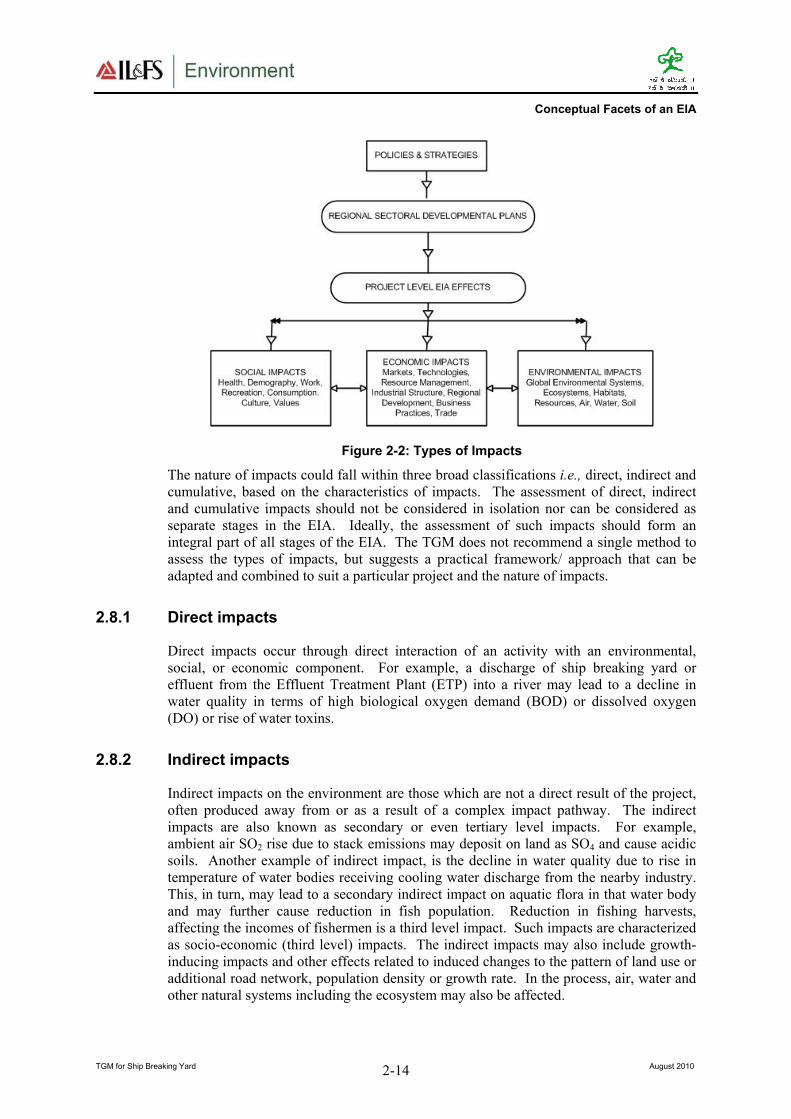
Figure 2-2: Types of Impacts
The nature of impacts could fall within three broad classifications i.e., direct, indirect and
cumulative, based on the characteristics of impacts. The assessment of direct, indirect
and cumulative impacts should not be considered in isolation nor can be considered as
separate stages in the EIA. Ideally, the assessment of such impacts should form an
integral part of all stages of the EIA. The TGM does not recommend a single method to
assess the types of impacts, but suggests a practical framework/ approach that can be
adapted and combined to suit a particular project and the nature of impacts.
2.8.1 Direct impacts
Direct impacts occur through direct interaction of an activity with an environmental,
social, or economic component. For example, a discharge of ship breaking yard or
effluent from the Effluent Treatment Plant (ETP) into a river may lead to a decline in
water quality in terms of high biological oxygen demand (BOD) or dissolved oxygen
(DO) or rise of water toxins.
2.8.2 Indirect impacts
Indirect impacts on the environment are those which are not a direct result of the project,
often produced away from or as a result of a complex impact pathway. The indirect
impacts are also known as secondary or even tertiary level impacts. For example,
ambient air SO2 rise due to stack emissions may deposit on land as SO4 and cause acidic
soils. Another example of indirect impact, is the decline in water quality due to rise in
temperature of water bodies receiving cooling water discharge from the nearby industry.
This, in turn, may lead to a secondary indirect impact on aquatic flora in that water body
and may further cause reduction in fish population. Reduction in fishing harvests,
affecting the incomes of fishermen is a third level impact. Such impacts are characterized
as socio-economic (third level) impacts. The indirect impacts may also include growth-
inducing impacts and other effects related to induced changes to the pattern of land use or
additional road network, population density or growth rate. In the process, air, water and
other natural systems including the ecosystem may also be affected.

Conceptual Facets of an EIA
TGM for Ship Breaking Yard August 2010 2-15
2.8.3 Cumulative impacts
Cumulative impact consists of an impact that is created as a result of the combination of
the projects evaluated in the EIA together with other projects in the same vicinity, causing
related impacts. Figure 2-3 depicts the same. Respective EAC may exercise their
discretion on a case-by-case basis for considering the cumulative impacts.
Figure 2-3: Cumulative Impact
2.8.4 Induced impacts
The cumulative impacts can be due to induced actions of projects and activities that may
occur if the action under assessment is implemented such as growth-inducing impacts and
other effects related to induced changes to the pattern of future land use or additional road
network, population density or growth rate (e.g. excess growth may be induced in the
zone of influence around the ship breaking industry, and in the process causing additional
effects on air, water and other natural ecosystems). Induced actions may not be officially
announced or be a part of any official plan. Increase in workforce and nearby
communities contributes to this effect.
They usually have no direct relationship with the action under assessment, and represent
the growth-inducing potential of an action. New roads leading from those constructed for
a project, increased recreational activities (e.g., hunting, fishing), and construction of new
service facilities are examples of induced actions.
However, the cumulative impacts due to induced development or third level or even
secondary indirect impacts are difficult to be quantified. Because of higher levels of
uncertainties, these impacts cannot normally be assessed over a long time horizon. An
EIA practitioner can only guess as to what such induced impacts may be and the possible
extent of their implications on the environmental factors. Respective EAC may exercise
their discretion on a case–by-case basis for considering the induced impacts.
2.9 Significance of impacts
This TGM establishes the significance of impacts first and proceeds to delineate the
associated mitigation measures. So the significance here reflects the “worst-case-
scenario” before mitigation is applied, and therefore provides an understanding of what
may happen if mitigation fails or if it is not as effective as predicted. For establishing
significance of different impacts, understanding the responses and interaction of the
environmental system is essential. Hence, the impact interactions and pathways are to be
understood and established first. Such an understanding will help in the assessment
process to quantify the impact as accurately as possible. Complex interactions,
Conceptual Facets of an EIA
TGM for Ship Breaking Yard August 2010 2-16
particularly in case of certain indirect or cumulative impacts, may give rise to non-linear
responses which are often difficult to understand and therefore their significance difficult
to assess. It is hence understood that indirect or cumulative impacts are more complex
than the direct impacts. Currently the impact assessments are limited to direct impacts.
In case mitigation measures are delineated before determining significance of the effect,
the significance represents the residual effects.
However, the ultimate objective of an EIA is to achieve sustainable development. The
development process shall invariably cause some residual impacts even after
implementing an EMP effectively. Environmentalists today are faced with a vital, not-
easy-to-answer question—“What is the tolerable level of environmental impact within the
sustainable development framework?” As such, it has been recognized that every
ecosystem has a threshold for absorbing deterioration and a certain capacity for self-
regeneration. These thresholds based on concept of carrying capacity are as follows:
Waste emissions from a project should be within the assimilative capacity of the local
environment to absorb without unacceptable degradation of its future waste
absorptive capacity or other important services.
Harvest rates of renewable resource inputs should be within the regenerative capacity
of the natural system that generates them; depletion rates of non-renewable inputs
should be equal to the rate at which renewable substitutes are developed by human
invention and investment.
The aim of this model is to curb over-consumption and unacceptable environmental
degradation. But because of limitation in available scientific basis, this definition
provides only general guidelines for determining the sustainable use of inputs and
outputs. To establish the level of significance for each identified impact, a three-stage
analysis may be referred:
First, an impact is qualified as being either negative or positive.
Second, the nature of impacts such as direct, indirect, or cumulative is determined
using the impact network
Third, a scale is used to determine the severity of the effect; for example, an impact is
of low, medium, or high significance.
It is not sufficient to simply state the significance of the effect. This determination must
be justified, coherent and documented, notably by a determination methodology, which
must be described in the methodology section of the report. There are many recognized
methodologies to determine the significance of effects.
2.9.1 Criteria/methodology to determine the significance of identified impacts
The criteria can be determined by answering some questions regarding the factors
affecting the significance. This will help the EIA stakeholders, the practitioner in
particular, to determine the significance of the identified impacts eventually. Typical
examples of such factors include the following:
Exceeding of a Threshold Limit: Significance may increase if the threshold is
exceeded. For e.g., Emissions of particulate matter exceed the permissible threshold.
Conceptual Facets of an EIA
TGM for Ship Breaking Yard August 2010 2-17
Effectiveness of Mitigation: Significance may increase as the effectiveness of
mitigation measures decreases. e.g., control technologies, which may not assure
consistent compliance to the requirements.
Size of Study Area: Significance may increase as the zone of effects increases.
Incremental Contribution of Effects from Action under Review: Significance may
increase as the relative contribution of an action increases.
Relative Contribution of Effects of Other Actions: Significance may decrease as the
significance of nearby larger actions increase.
Relative Rarity of Species: Significance may increase as species becomes
increasingly rare or threatened.
Significance of Local Effects: Significance may increase as the significance of local
effects is high.
Magnitude of Change Relative to Natural Background Variability: Significance may
decrease if effects are within natural assimilative capacity or variability.
Creation of Induced Actions: Significance may increase activities also highly
significant.
Degree of Existing Disturbance: Significance may increase if the surrounding
environment is pristine.
For determining the significance of impacts, it is important to remember that secondary
and higher order effects can also occur as a result of a primary interaction between the
project activity and local environment. Wherever a primary effect is identified, the
practitioner should always think if secondary or tertiary effects on other aspects of the
environment could also arise.
The EIA should also consider the effects that could arise from the project due to induced
developments, which take place as a consequence of the project. For e.g., population
density and associated infrastructure and jobs for people attracted to the area by the
project. It also requires consideration of cumulative effects that could arise from a
combination of the effects due to other projects with those of other existing or planned
developments in the surrounding area. So the necessity to formulate qualitative checklist
is suggested to test significance, in general.

Ship Breaking Yard
TGM for Ship Breaking Yard August 2010 3-1
3. ABOUT SHIP BREAKING YARD INCLUDING BEST
PRACTICES AND POLLUTION CONTROL TECHNOLOGIES
3.1 Introduction
A ship can be defined as a vessel of any type whatsoever operating under its own power
or otherwise in the marine environment, including hydrofoil boats, air-cushion vehicles,
and submersibles, floating craft, and fixed or floating platforms, and a vessel that has
been stripped of equipment, or is towed.
The Ministry of Steel in pursuance to Supreme Court of India directive brought ‘Draft
Comprehensive Code on Ship Recycling Regulations’. This code defines the ship as a
vessel and other floating structures for breaking. Ship ceases to be a ship once bill of
entry for home consumption is filed with the customs declaring it as cargo (for
demolition). It is suggested that this definition must be followed in the interest of Indian
ship breaking yards.
Based on their use, ships may be categorized as commercial, fishing, and military vessels.
Commercial vessels in turn can be broadly classified as cargo, passenger and special
purpose ships. Fishing vessels can be made a subset of commercial vessels. However,
their size is very small. Military or naval vessels can be categorized as warships,
submarines, support and auxiliary vessels, combat vessels, battleships and many others.
Yields vary with the category of ship, and also with the environmental concerns. Thus it
is important to understand the categories of ships. Some of these ship categories are
discussed below:
Cargo Ships: These transport dry and liquid cargo. Dry cargo is carried in bulk
carriers, container ships, and general cargo ships. Liquid cargo is generally carried in
bulk abroad in chemical tankers, oil tankers and LNG tankers.
− Bulk Carriers: Used to carry ore, grains, cattle, phosphates, coal, soyabeans,
China clay, etc.
General Cargo Ships: These carry all types of products such as big bags (containing
food products like cocoa and coffee beans) and large machine parts except products
or liquids in bulk. These ships are increasingly replaced by container ships.
− Container Ships: These ships carry medicines, food products, machinery, powder
chemicals, household appliances and computers. Container ships are considered
as an important means of transport for the future and its major advantage is its
handling efficiency.
− Chemical Tankers: They carry liquids like Sulphuric acid, Phosphoric acid,
Phenols, etc. They also carry products like molasses and edible oils like palm oil,
vegetable oils.
− Oil Tankers: These are of two types — crude and product tankers. Crude tankers
carry large quantities of unrefined crude oil from its point of extraction to

Ship Breaking Yard
TGM for Ship Breaking Yard August 2010 3-2
refineries. Product tankers, on the other hand, are designed to move
petrochemicals from refineries to points near consuming markets.
− LNG Tankers: These ships are designed to transport Liquefied Natural Gas.
Passengers: Passenger ships range in size from small river ferries to giant cruise
ships. These can be categorized as ferries, ocean liners and cruise ships. These ships
carry passengers and can sail on much longer as the ships are maintained in a good
condition.
− Cruise Ships: These are used for pleasure voyages. Cruise ships operate mostly
on routes that return passengers to their originating port.
− Ferries: Ferries are used to transport freight (Lorries and containers) and even
railroad cars. Most ferries operate on regular, frequent and return services.
These also form the part of public transport systems of many waterside cities and
islands.
− Ocean Liners: These are designed to transport people from one seaport to another
along regular long-distance maritime routes according to the schedule. These are
strongly built with high freeboards to withstand sea states and adverse conditions
encountered in the Open Ocean and stores large capacities of fuel, victuals and
other stores, which could be consumed on voyages which take several days to
weeks.
Special Purpose Vessels (SPV): These ships are designed to perform specific tasks
and include tugboats, pilot boats, rescue boats, cable ships, research vessels, survey
vessels and ice breakers.
− Drill Ships: These are fitted with drilling apparatus for exploratory drilling of
new oil or gas wells in deep waters. Drill ships can drill in water depths of over
2000 metres (m).
War Ships: These ships carry weapons, ammunition and supplies for its crew.
Fishing Vessels: These are used to catch fish in the sea, lake or river. Different kinds
of vessels are used for commercial and recreational fishing. Based on the type of
fish, fishing method, and geographical origin there are different categories of fishing
vessels.
Ship breaking is an inseparable part of the shipping business. For as long as ships have
existed, ‘ship breaking’, has been the way ships ended their lives if they are not lost at the
sea. Compared to ship building, ship breaking is a rough business. Most of the world’s
ship breaking industry uses manual labour to dismantle ships.
In the 18th century, ships were sold to a breaker for recovery of spare parts, firewood, iron
and brass parts for continued use in new ships or for re-melting. Everything was reused
in some way. The economics of the system was very straightforward - the owner receives
money for his ship; the breaker receives enough money for his scrap to pay his expenses
and make a profit.
Dismantling of vessels was a common scene at the ports, especially throughout Southern
Europe from the late 1940s to the 1960s.

Ship Breaking Yard
TGM for Ship Breaking Yard August 2010 3-3
Till early 1980’s vessels were scrapped in Japan, Korea and Taiwan. However, for the
last 25 years, India, Bangladesh and Pakistan have been the global centers for ship
breaking Industry. Here, the ships are scrapped directly on the beaches or the vast
inter-tidal mudflats exposed daily by about 10m tidal gauge. The beaching method of the
Indian sub-continent relies heavily on low labour cost, since it involves very little
mechanisation.
Each year between 200 and 600 sea-going ships of over 2,000 dead weight tonnage (dwt)
are dismantled worldwide. This number may significantly increase, if the decision on
replacement of single hull tankers comes into effect.
Single hull tankers are more likely than double hull vessels to rupture and break up, and
spill oil into the sea. As per the International Maritime Organization (IMO) regulations,
single hull tankers are phased out or converted to a double hull after certain age for the
prevention of oil spills and pollution from ships. The double hull is designed to reduce
the risk of oil spills from tankers involved in low energy collisions or groundings during
the most critical part of a voyage.
A ship consists mostly of steel. Consequently, at the end of its useful life, it becomes a
sought-after source of ferrous scrap particularly suited for reprocessing into simple steel
products such as steel rods used in civil construction. The geographical migration of
scrapping locations mirrors the global industrial economic development. It seeks areas
providing:
Sea beach
Demand for scrap steel for reprocessing
Demand for second-hand equipment and
Supply of low-cost labour to carry out the labour-intensive extraction process
The vast majority of waste stream generated following the demolition or scrapping
process is largely returned to good use. Usable equipment such as pumps, motors, valves,
generators, etc., is sold out which finds alternative applications and the scrap steel is
reprocessed. The latter, as an alternative to steel production from ore, represents a
significant savings in energy consumption perspective. Ship-scrapping is truly a
sustainable activity from a resource utilization point-of-view.
Steel scrap obtained from tankers that have large flat panels is comparatively of higher
quality. In developing countries, the scrap is simply heated and re-rolled into concrete
reinforcing rods for sale to the construction industry, but this may not meet the Bureau of
Indian Standards (BIS) standard. Re-rolled steel is also ideal for sewage projects, metal
rods and agricultural needs. In the advanced countries, scrap is completely melted down
to make fresh steel.
Non-ferrous items like diesel engines, generators, deck cranes, compasses and other
fixtures also offer lucrative returns when resold. Again the market for such items is more
readily available in developing countries than in developed countries where technical
standards are more demanding and refurbishing costs are higher.
On the flip side, ship-scrapping is not so user-friendly when the means adopted are
considered and the consequences it generates are compared with respect to occupational
safety, health and environment. The extent of damage caused by ship-scrapping to the
environment and to the livelihood of the fishermen, peasants that share the environment,
and to the lives and health of workers involved in these activities would include:

Ship Breaking Yard
TGM for Ship Breaking Yard August 2010 3-4
Costs for loss of livelihood
Clean up costs for polluted sediments
Costs for asbestos liabilities
Medical and compensation costs for losing the ability to work
Medical and compensation costs for deaths and diseases caused by exposure to toxic
substances, etc.
3.1.1 Ship breaking in India
Ship breaking is not new to India and this activity has been going on ever since 1912 in
Kolkata and Mumbai. Steel scrap was worthwhile even then and countries that had yards
to recycle ships were often considered to be economically fortunate.
When the first economic recession came around 1984 and the fleet owners thought that it
was better to scrap ships than to maintain them, there was a huge backlog of ships to be
demolished. As a result, labour got very expensive and sale of steel scrap failed to fetch
profits. Meanwhile, India and some other eastern countries offered cheaper labour and
hence became the destination for ship-scrapping industry. Due to increased import of
ships for breaking, an emphasis was laid to examine various sites suitable for this activity.
Considering the favourable parameters for beaching method like high tidal range, firm
seabed, gentle seaward slope, etc., it was decided to set up a ship breaking yard in the
western coast of Gulf of Cambay near Alang village. The first vessel – M.V Kota
Tenjong was beached at Alang on 13th February, 1983. Since then, the yard has
witnessed significant growth and has emerged as a leading ship breaking yard in the
world.
The CPCB in Delhi has prepared environmental guidelines for ship-scrapping industries
aiming to minimise the effect of the yards on the surrounding environment through proper
location of breaking yards and by preparing and implementing an EMP and an
Emergency Management Plan.
The guidelines include a description of the appropriate pollution control measures
regarding solid waste, air pollution, water pollution and noise. This also includes aspects
of workers’ safety.
The Gujarat Maritime Board (GMB) has issued regulations covering safety measures for
beaching of vessels since the year 2000. Substance of the regulation was the
documentation of a gas-free certificate before beaching and a permission to start the
cutting operations to be issued by the GMB following the removal of hazardous materials
from the vessel. The gas-free certificate was introduced in 2001.
Indian Supreme Court order of 14th October, 2003 on Hazardous Waste Management
Rules, directs that the SPCB should ensure that the ship is properly decontaminated by
the ship owner before breaking.
In June 2007, the Supreme Court of India established a panel to develop standard
procedures and environment protocols for the Indian ship breaking industry.
3.1.2 Process of ship procurement for scrapping in India
Ship-owners who have decided to end the economic life of a vessel will contact
demolition brokers who in turn look for a cash buyer. This basically happens when the
maintenance cost of the vessel starts to exceed possible revenue, or when the vessel has
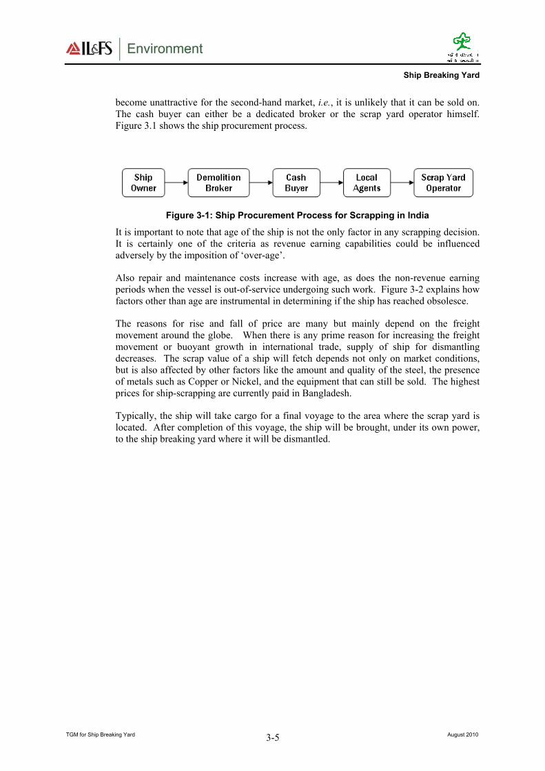
Ship Breaking Yard
TGM for Ship Breaking Yard August 2010 3-5
become unattractive for the second-hand market, i.e., it is unlikely that it can be sold on.
The cash buyer can either be a dedicated broker or the scrap yard operator himself.
Figure 3.1 shows the ship procurement process.
Figure 3-1: Ship Procurement Process for Scrapping in India
It is important to note that age of the ship is not the only factor in any scrapping decision.
It is certainly one of the criteria as revenue earning capabilities could be influenced
adversely by the imposition of ‘over-age’.
Also repair and maintenance costs increase with age, as does the non-revenue earning
periods when the vessel is out-of-service undergoing such work. Figure 3-2 explains how
factors other than age are instrumental in determining if the ship has reached obsolesce.
The reasons for rise and fall of price are many but mainly depend on the freight
movement around the globe. When there is any prime reason for increasing the freight
movement or buoyant growth in international trade, supply of ship for dismantling
decreases. The scrap value of a ship will fetch depends not only on market conditions,
but is also affected by other factors like the amount and quality of the steel, the presence
of metals such as Copper or Nickel, and the equipment that can still be sold. The highest
prices for ship-scrapping are currently paid in Bangladesh.
Typically, the ship will take cargo for a final voyage to the area where the scrap yard is
located. After completion of this voyage, the ship will be brought, under its own power,
to the ship breaking yard where it will be dismantled.
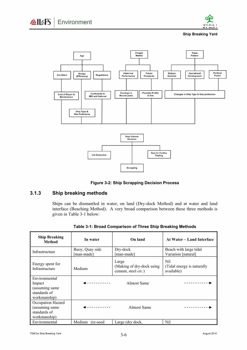
Ship Breaking Yard
TGM for Ship Breaking Yard August 2010 3-6
Figure 3-2: Ship Scrapping Decision Process
3.1.3 Ship breaking methods
Ships can be dismantled in water, on land (Dry-dock Method) and at water and land
interface (Beaching Method). A very broad comparison between these three methods is
given in Table 3-1 below:
Table 3-1: Broad Comparison of Three Ship Breaking Methods
Ship Breaking
Method In water On land At Water – Land Interface
Infrastructure Buoy, Quay side
[man-made]
Dry-dock
[man-made]
Beach with large tidal
Variation [natural]
Energy spent for
Infrastructure
Medium
Large
(Making of dry-dock using
cement, steel etc.)
Nil
(Tidal energy is naturally
available)
Environmental
Impact
(assuming same
standards of
workmanship)
Almost Same
Occupation Hazard
(assuming same
standards of
workmanship)
Almost Same
Environmental Medium (re-used Large (dry dock, Nil
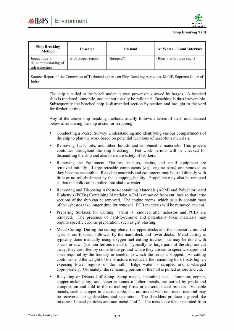
Ship Breaking Yard
TGM for Ship Breaking Yard August 2010 3-7
Ship Breaking
Method In water On land At Water – Land Interface
Impact due to
de-commissioning of
infrastructure
with proper repair) ‘dumped’)
(Beach remains as such)
Source: Report of the Committee of Technical experts on Ship Breaking Activities, MoEF, Supreme Court of
India
The ship is sailed to the beach under its own power or is towed by barges. A beached
ship is rendered immobile, and cannot usually be refloated. Beaching is thus irreversible.
Subsequently the beached ship is dismantled section by section and brought to the yard
for further cutting.
Any of the above ship breaking methods usually follows a series of steps as discussed
below after towing the ship at site for scrapping:
Conducting a Vessel Survey: Understanding and identifying various compartments of
the ship to plan the work based on potential locations of hazardous materials.
Removing fuels, oils, and other liquids and combustible materials: This process
continues throughout the ship breaking.. Hot work permits will be checked for
dismantling the ship and also to ensure safety of workers.
Removing the Equipment: Fixtures, anchors, chains, and small equipment are
removed initially. Large reusable components (e.g., engine parts) are removed as
they become accessible. Reusable materials and equipment may be sold directly with
little or no refurbishment by the scrapping facility. Propellers may also be removed
so that the hulk can be pulled into shallow water.
Removing and Disposing Asbestos-containing Materials (ACM) and Polychlorinated
Biphenyls (PCBs) Containing Materials: ACM is removed from cut lines so that large
sections of the ship can be removed. The engine rooms, which usually contain most
of the asbestos take longer time for removal. PCB materials will be removed and cut.
Preparing Surfaces for Cutting: Paint is removed after asbestos and PCBs are
removed. The presence of hard-to-remove and potentially toxic materials may
require specific cut-line preparation, such as grit blasting.
Metal Cutting: During the cutting phase, the upper decks and the superstructure and
systems are first cut, followed by the main deck and lower decks. Metal cutting is
typically done manually using oxygen-fuel cutting torches, but may be done with
shears or saws (for non-ferrous metals). Typically, as large parts of the ship are cut
away, they are lifted by crane to the ground where they are cut to specific shapes and
sizes required by the foundry or smelter to which the scrap is shipped. As cutting
continues and the weight of the structure is reduced, the remaining hulk floats higher,
exposing lower regions of the hull. Bilge water is sampled and discharged
appropriately. Ultimately, the remaining portion of the hull is pulled ashore and cut.
Recycling or Disposal of Scrap: Scrap metals, including steel, aluminum, copper,
copper-nickel alloy, and lesser amounts of other metals, are sorted by grade and
composition and sold to the re-melting firms or to scrap metal brokers. Valuable
metals, such as copper in electric cable, that are mixed with non-metal material may
be recovered using shredders and separators. The shredders produce a gravel-like
mixture of metal particles and non-metal ‘fluff’. The metals are then separated from
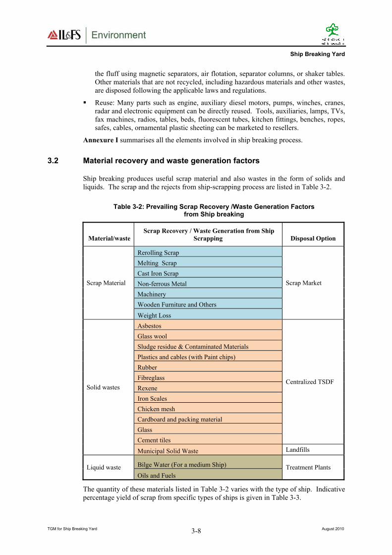
Ship Breaking Yard
TGM for Ship Breaking Yard August 2010 3-8
the fluff using magnetic separators, air flotation, separator columns, or shaker tables.
Other materials that are not recycled, including hazardous materials and other wastes,
are disposed following the applicable laws and regulations.
Reuse: Many parts such as engine, auxiliary diesel motors, pumps, winches, cranes,
radar and electronic equipment can be directly reused. Tools, auxiliaries, lamps, TVs,
fax machines, radios, tables, beds, fluorescent tubes, kitchen fittings, benches, ropes,
safes, cables, ornamental plastic sheeting can be marketed to resellers.
Annexure I summarises all the elements involved in ship breaking process.
3.2 Material recovery and waste generation factors
Ship breaking produces useful scrap material and also wastes in the form of solids and
liquids. The scrap and the rejects from ship-scrapping process are listed in Table 3-2.
Table 3-2: Prevailing Scrap Recovery /Waste Generation Factors from Ship breaking
Material/waste
Scrap Recovery / Waste Generation from Ship
Scrapping Disposal Option
Scrap Material
Rerolling Scrap
Scrap Market
Melting Scrap
Cast Iron Scrap
Non-ferrous Metal
Machinery
Wooden Furniture and Others
Weight Loss
Solid wastes
Asbestos
Centralized TSDF
Glass wool
Sludge residue & Contaminated Materials
Plastics and cables (with Paint chips)
Rubber
Fibreglass
Rexene
Iron Scales
Chicken mesh
Cardboard and packing material
Glass
Cement tiles
Municipal Solid Waste Landfills
Liquid waste Bilge Water (For a medium Ship) Treatment Plants
Oils and Fuels
The quantity of these materials listed in Table 3-2 varies with the type of ship. Indicative
percentage yield of scrap from specific types of ships is given in Table 3-3.
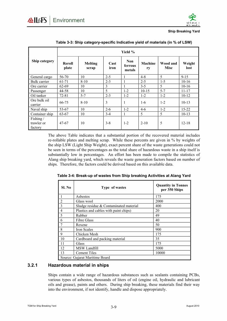
Ship Breaking Yard
TGM for Ship Breaking Yard August 2010 3-9
Table 3-3: Ship category-specific Indicative yield of materials (in % of LSW)
Ship category
Yield %
Reroll
plate
Melting
scrap
Cast
iron
Non
ferrous
metals
Machine
ry
Wood and
Misc
Weight
lost
General cargo 56-70 10 2-5 1 4-8 5 9-15
Bulk carrier 61-71 8-10 2-3 1 2-5 1-5 10-16
Ore carrier 62-69 10 3 1 3-5 5 10-16
Passenger 44-58 10 5 1-2 10-15 5-7 11-17
Oil tanker 72-81 5-7 2-3 1-2 1-2 1-2 10-12
Ore bulk oil
carrier 66-75 8-10 3 1 1-6 1-2 10-13
Naval ship 53-67 10 2-6 1-2 4-6 1-2 15-22
Container ship 63-67 10 3-4 1 5 5 10-13
Fishing /
trawler or
factory
47-67 10 3-8 1-2 2-10 5 12-18
The above Table indicates that a substantial portion of the recovered material includes
re-rollable plates and melting scrap. While these percents are given in % by weights of
the ship LSW (Light Ship Weight), exact percent share of the waste generations could not
be seen in terms of the percentages as the total share of hazardous waste in a ship itself is
substantially low in percentages. An effort has been made to compile the statistics of
Alang ship breaking yard, which reveals the waste generation factors based on number of
ships. Therefore, the factors could be derived based on this available data.
Table 3-4: Break-up of wastes from Ship breaking Activities at Alang Yard
Sl. No Type of wastes Quantity in Tonnes
per 350 Ships
1 Asbestos 175
2 Glass wool 2000
3 Sludge residue & Contaminated material 400
4 Plastics and cables with paint chips) 20
5 Rubber 49
6 Fibre Glass 40
7 Rexene 50
8 Iron Scales 900
9 Chicken Mesh 175
10 Cardboard and packing material 35
11 Glass 175
12 MSW Landfill 5000
13 Cement Tiles 10000
Source: Gujarat Maritime Board
3.2.1 Hazardous material in ships
Ships contain a wide range of hazardous substances such as sealants containing PCBs,
various types of asbestos, thousands of liters of oil (engine oil, hydraulic and lubricant
oils and grease), paints and others. During ship breaking, these materials find their way
into the environment, if not identify, handle and dispose appropriately.

Ship Breaking Yard
TGM for Ship Breaking Yard August 2010 3-10
Potential hazardous materials which may be on board the ships that are delivered to ship
breaking facilities as per Supreme Court Committee of experts are listed below.
Operational Substances and Consumables
− Cargo residues including slops
− Dry tank residues
− Fuel oil, Diesel oil, Gas oil, Lubricating oil, Greases & Anti-seize Compounds
− Hydraulic oil
− Waste oils (contents of sludge tank)
− Antifreeze fluids
− Kerosene and White Spirit
− Boiler and Feed Water Treatment Chemicals
− Boiler and Feed Water Test Re-agents
− De-ioniser Regenerating Chemicals
− Evaporator Dosing and Descaling Acid
− Domestic Water treatment Chemicals
− Paints and Rust Stabilizers
− Solvents and Thinners
− Refrigerants (R12 or R22)
− HALON
− CO2 (in cylinders - engine room fire protection)
− Acetylene, Propane and Butane
− Hotel Services Cleaners
− Lead-acid Batteries
− Battery Electrolyte
− PCB and/or PCT and/or PBB at levels of 50 mg/kg or more
− Mercury
− Radio-active Material i.e,. liquid level indicators
− Miscellaneous Medicines
− Insecticide Spray
− Miscellaneous Chemicals such as Alcohol, Methylated Spirits, Epoxy Resins, etc.
− Plastics as covered by MARPOL
− Raw and Treated Sewage
− Perfluorocarbons (PFCs)
Toxic Materials (as part of the ship‘s structure)
− Asbestos
− Lead-based Paint Coatings on Ship‘s Structure
− Tin-based Anti-fouling Coatings on Ship’s Bottoms
− Others
The hazardous wastes and substances during ship breaking process as listed in the ‘Report
of the Committee of Technical Experts on Ship Recycling Activities’, Writ Petition
No.657 of 1995, MoEF and Supreme Court Monitoring Committee is provided in
Annexure II. Also the disposal options for the waste identified on the ship are provided
in Annexure III.
3.2.2 Specific wastes of concern from ship breaking process and their management
Ship breaking process creates potential releases to the environment (air, water and land)
due to:
Ship Breaking Yard
TGM for Ship Breaking Yard August 2010 3-11
Insufficiencies in preparatory procedures prior to dismantling process
Inability to collect, remove, secure on board materials of concern during dismantling
Insufficiencies in procedures related to the collection, storage, transport and disposal
of substances
It is necessary to safeguard against these impacts on environment and health by taking
corrective actions at appropriate stages of ship dismantling. Following a proper ship
dismantling process would safeguard most of the environmental and health issues.
Inventory of hazardous wastes on board: Hazardous waste inventory that identifies,
quantifies and locates the type of waste on board should be carried out before the ship
comes to the shore. Chemical safety data sheets should be made available for each
hazardous substance that is identified. As per the High Power Committee,
maintaining the complete inventory of hazardous wastes on board is a mandatory task
for any ship owner. This inventory shall be submitted by the State Maritime Board to
the SPCB to ensure safe disposal of hazardous waste. Further permissions for ship
anchoring and beaching will be based on hazardous waste inventory.
Removing and cleaning of liquids, fuels and oils: Before start of ship dismantling, all
the liquid residues should be removed and cleaned from the ship. This process may
continue during the entire ship dismantling process.
Safety and Security: There should be a safe working and operating procedures
ensuring safe accessibility to all the areas and compartments of the ship and safe
conditions for hot work.
Removal of equipments: The consumable and loose equipment, which are easily
accessible, should be removed first.
Removal of Hazardous materials: The hazardous wastes identified by the inventory
data is properly removed and disposed.
Dismantling plan: Safe and practical cutting sequence is to be followed (Beaching
method or dry-dock method or moored method). Dismantling plan should be drawn
before start of the work. This plan forms the basis for sectional breaking of the ship
Proper storage, breaking and disposal of waste: Waste obtained during dismantling is
sorted and segregated based on the type of waste and disposal option.
Specific wastes from the ship breaking yard are as follows:
− Asbestos
− Polychlorinated biphenyls (PCBs)
− Bilge and ballast waters
− Oils and fuels
− Metal cutting
− Paints
Removal and Disposal of Miscellaneous Ship Machinery
Techno-scientific and best management practices can be applied for handling, storing and
disposing the hazardous materials generated during ship breaking process to ensure safety
and health of the workers at the facility. Some of the handling and protective measures
with respective environmental and health hazards are discussed in the following sections.
The summary of the preventive measures for these hazards along with the media of
Ship Breaking Yard
TGM for Ship Breaking Yard August 2010 3-12
contamination and pathways is given in Annexure IV. Pollutant-specific details on
sources in ship, hazards, potential impacts, removal practices and procedures from the
ship are discussed in the following sections.
3.2.2.1 Asbestos
Asbestos is a mineral with long, thin fibrous crystals. It is resistant to heat, electricity and
chemical damage and has sound absorption and tensile strength. Asbestos, earlier viewed
as a kind of miracle material, was widely used in ship building, particularly for insulation.
Many products used on ships such as gaskets, valves, cables, adhesives, etc., contain
asbestos. However, the risks associated with asbestos — including the risk of
mesothelioma cancer and other lung diseases caused by inhaling the toxic fibres—makes
it a hazardous material to be dealt with. Hence the workers’ exposure to asbestos in ship
breaking activities, especially those involved in the removal and disposal of asbestos is
considered a primary environmental health and safety concern.
A) Sources in ships
Bulkhead and pipe thermal insulation
Bulkhead fire shields/fireproofing
Uptake space insulation
Exhaust duct insulation
Electrical cable materials
Brake linings
Floor tiles and deck underlay
Steam, water, and vent flange gaskets
Adhesives and adhesive-like glues (e.g., mastics) and fillers
Sound damping
Molded plastic products (e.g., switch handles, clutch facings)
Sealing putty
Packing in shafts and valves
Packing in electrical bulkhead penetrations
Asbestos arc chutes in circuit breakers
Pipe hanger inserts
Weld shop protectors and burn covers,
Blankets, and any firefighting clothing or equipment
Any other type of thermal insulating material
B) Hazards
Workers may be exposed to asbestos while working on dismantling of ships –especially
when removing asbestos-bearing thermal insulation; handling of circuit breakers, cable,
cable penetrations; and removing floor tiles (from asbestos in the mast and in the tile).
Asbestos fibres are minute, light and hence can remain suspended in air for longer
periods. There are very high chances of workers inhaling these particles found suspended
in these areas. Airborne asbestos fibres are small, odorless, and tasteless. They range in
size from 0.1 to 10 microns in length (a human hair is about 50 microns in diameter).
Additional concerns can arise from handling and removing gaskets with piping and
electrical systems, as well as molded plastic parts.
Para-occupational Exposure: Workers’ families may inhale asbestos fibres released by
their clothes that have been in contact with the ACM.
Ship Breaking Yard
TGM for Ship Breaking Yard August 2010 3-13
Neighborhood Exposure: People who live or work near asbestos- related operations may
inhale asbestos fibres that have been released into the air by these operations.
C) Potential impacts
Asbestos affects the lungs resulting in loss of lung function that often progresses to
disability or to death. Prolonged exposure to asbestos may also result in cancer affecting
various organs – mesothelioma (cancer affecting the membranes lining the lungs and
abdomen), lung cancer, or cancers of the oesophagus, stomach, colon, and rectum. If
inhaled, asbestos fibres can easily penetrate the body tissues, and may be deposited and
retained in the respiratory tract and lung tissue. Because asbestos fibres remain in the
body, each exposure increases the likelihood of developing an asbestos-related disease.
Asbestos-related diseases may not appear until years after exposure. Ingesting asbestos
may be harmful, but the consequences of this type of exposure have not been clearly
documented yet. It is noted that risks of asbestos exposure are multiplied 10-fold or more
if a worker smokes.
D) Asbestos removal practices and procedures
i) Workers’ protection
The facility has to perform air surveillance activities in work areas where asbestos is
being removed, including meeting the general monitoring criteria, conducting initial
exposure assessments, and performing daily and periodic monitoring.
The facility must keep an accurate record of all measurements taken to monitor the
workers’ exposure to asbestos.
Facility is required to conduct medical surveillance for all workers who, for a
combined total of 30 or more days per year, are performing asbestos removal work or
are exposed at or above the permissible exposure limit. This includes medical
examination and consultation prior to beginning work, at least annually, and upon
termination of employment.
The facility must establish and maintain an accurate record for each worker subject to
medical surveillance. These records must be maintained for the duration of the
worker’s employment, plus an additional 30 years.
Restrict working hours to a maximum of four hours in activities involving asbestos
handling.
ii) Worker exposure limits
Facility must ensure that workers are not exposed to air-borne asbestos concentrations in
excess of either of the following Permissible Exposure Limits (PELs).
0.1 fibre per cubic centimetre (f/cc) of air averaged over an eight-hour work shift.
This PEL is called the time-weighed average (TWA) limit
1.0 f/cc of air averaged over a sampling period of 30 minutes. This PEL is called the
excursion limit.

Ship Breaking Yard
TGM for Ship Breaking Yard August 2010 3-14
iii) Workers’ training
Facility must provide, at no cost, a training program for employees likely to be
exposed to asbestos removal work during the ship breaking.
Workers should be trained prior to or at the time of beginning the job and at least
once a year afterwards. For asbestos removal operations that require the use of
critical barriers and/or negative pressure enclosures, the facility must provide training
to workers.
The supervisors must be trained about the regulations and the means of compliance.
Training must at least include: the application of regulations; notification
requirements; material identification procedures; emission control procedures for
removals; waste disposal practices; reporting and recordkeeping; and asbestos
hazards and worker protection.
iv) Training records
The facility must document the trainings attended and completed by each worker and
supervisor. These records must be maintained for one year past the last day of
employment.
PPE is required to ensure that the workers involved in asbestos removal and disposal
are using approved respirators. Respirators appropriate for the work being conducted
must be provided free-of-charge by the facility. In addition, the facility is required to
provide and ensure the use of protective clothing, such as cover-alls or similar
full-body clothing, head coverings, gloves, and foot covering, to be used by the
workers during the asbestos removal work. In addition, the facility should make sure
that appropriate PPE like face shields, vented goggles are provided and used
wherever the possibility of eye irritation exists.
v) Hygiene facilities for workers
A decontamination area which includes equipment room, shower area, clean room
located adjacent to the regulated area for decontamination should be provided by the
facility to the workers exposed to asbestos.
The facility must provide lunch areas in which the airborne concentrations of asbestos
are below the PELs.
Supervisor must oversee the activities related to the stripping, removing or handling
of Regulated Asbestos Containing Material (RACM).
vi) Supervisors’ responsibilities
Supervisors’ (commonly called the qualified person) responsibilities would include:
Setting up of the regulated area, enclosure, or other containment; and ensure the
integrity of the enclosure or containment.
Set up procedures to control the entry and exit the area and/or enclosure.
Supervise the ‘All Workers’ Exposure Monitoring Programme’ and ensure that it is
properly conducted.
Ensure that the employees working within the enclosure using the PPE.
Ship Breaking Yard
TGM for Ship Breaking Yard August 2010 3-15
Verify if the workers use the hygiene facilities and observe the decontamination
procedures.
Ensure thorough on-site inspection proper set up, use and functioning of the
engineering controls.
Ensure that the RACM is adequately wet when removed and remains wet until
collected and contained for disposal. RACM contained in a leak-tight wrapping
needs not be wetted.
ACM must be carefully lowered to the ground without being dropped, thrown, slid, or
otherwise damaged or disturbed.
ACM must be moved to the ground via leak-tight chutes or containers if removed
from more than 50-feet above the ground (and not removed as a unit or section).
When removing the RACM, facility is required to control visible emissions of
asbestos to the outside air because no safe concentration of air-borne asbestos has
ever been established
E) Best operating practices to control asbestos emissions
Adequately wet RACM exposed during cutting or disjoining; and a misting unit can
be used to create a high level of humidity within a removal area. It is believed that
the fibres emitted into a saturated environment will absorb the wetting agent and fall
out of the air faster, thus reducing airborne asbestos fibre levels.
Carefully lower each unit or section to the floor and to the ground level without
dropping, throwing, sliding, or otherwise damaging or disturbing the RACM
After removal, these units or sections must be wrapped in leak-tight wrapping or
stripped of RACM. If stripped, workers must:
− Adequately wet the RACM during stripping or
− Use local exhaust ventilation and collection system designed and operated to
capture the particulate asbestos materials produced by the stripping.
− The system must exhibit no visible emissions to the outside air.
Cable stripping areas are usually treated as regulated areas because stripping produces
fluff which may contain asbestos.
Each regulated area must meet the following requirements:
− Regulated areas must be marked in any manner that limits the number of workers
in the area, and protects workers outside the area from exposure to airborne
asbestos
− Only authorized workers should have access to the regulated areas.
− All workers entering and working in these areas must wear approved respirators.
It should be noted that all the workers must be medically approved to wear
respirators and be part of a respirator protection program.
− Workers must not be allowed to eat, smoke, drink, or chew tobacco or gum in
regulated areas.
− Under the asbestos abatement requirements, the facility must have a qualified
person to supervise the work conducted in a regulated area.
− Workers performing asbestos removal must enter and exit the regulated area
through a three-stage decontamination area.
Ship Breaking Yard
TGM for Ship Breaking Yard August 2010 3-16
F) Engineering controls and work practices during removal of asbestos
Because many workers may not be able to read or understand signs in English, post
signs in English and also other languages as appropriate.
In addition to the emission controls (e.g., wet methods, prompt clean up and disposal
of RACM wastes) described above, asbestos removal work must be performed using
control methods, such as vacuum cleaners equipped with high efficiency particulate
air (HEPA) filters to collect all debris and dust containing ACM.
In addition, to achieve compliance with permissible exposure limits, the facility must
use control methods including, but not limited to:
− Local exhaust ventilation equipped with HEPA filter dust collection systems.
− Enclosure or isolation of those processes producing asbestos dust.
− Ventilation of the regulated area to move contaminated air away from the
breathing zone of workers and towards a filtration or collection device equipped
with a HEPA filter.
To ensure that airborne asbestos does not migrate from the regulated area, facility can
also use critical barriers or another barrier or isolation method. A critical barrier is
one or more layers of plastic sealed over all openings into a work area or any other
physical barrier sufficient to prevent airborne asbestos in the work area from
migrating to an adjacent area.
Negative Pressure Enclosure Systems: In a negative pressure enclosure (NPE), air is
changed at least four times per hour and is directed away from workers within the
enclosure and towards a HEPA filtration or collection device. The NPE is kept under
negative pressure throughout the period of its use. There is also a requirement to
maintain a minimum of -0.02 column inches of water pressure differential. This is
normally accomplished with a manometer.
Glove bag system is a sealed compartment with attached inner gloves for the handling
of ACM. Properly installed and used, glove bags provide a small work area enclosure
and may be used to remove ACM from straight runs of piping and elbows and other
connections.
Negative pressure glove bag systems are similar to the glove bags described above,
except a HEPA vacuum system or other device is attached to the bag. They may be
used to remove ACM from piping.
Negative pressure glove box systems: Glove boxes, which have rigid sides, are made
from metal or another material which can withstand the weight of the ACM and water
used during removal. A HEPA filtration system is used to maintain the negative
pressure in the box. These systems can be used to remove ACM from pipe runs.
Water spray process system can be used for the removal of ACM and Presumed
Asbestos Containing Material (PACM) from cold line piping.
After wetting, the facility must seal all Asbestos Containing Waste Material (ACWM)
in leak-tight containers while it is still wet. The containers can be plastic bags,
cartons, drums, or cans. For bulk wastes that will not fit into containers without
additional recycling, the facility must put these wastes into leak-tight wrapping. The
wrapping should be sealed (e.g., with duct tape) while adequately wet. If the ACWM
is placed directly in trailers or roll-off boxes, the trailers or boxes should first be lined
Ship Breaking Yard
TGM for Ship Breaking Yard August 2010 3-17
with plastic sheeting. After the ACWM is loaded, the trailer or roll-off box should be
covered with a tarp while the ACWM is adequately wet.
Some facilities are implementing a new policy to let no regulated materials touch the
ground. Asbestos containers are being placed on the ship, and then directly
transported for disposal when they come off the ship. In all cases, the ACWM should
be wet when contained to prevent the release of asbestos fibres in case the container
or wrapping is broken.
Facility must send all ACWM to an authorized disposal site that receives ACWM.
3.2.2.2 Polychlorinated biphenyls (PCBs)
PCBs are man-made organic chemicals used in electrical, heat transfer, and hydraulic
equipment; as plasticisers in paints, plastics and rubber products, etc.
PCBs are found all over the older vessels and it is likely that a ship breaking facility may
be faced with managing large quantities of PCBs. PCBs belong to a broad family of
man-made organic chemicals known as chlorinated hydrocarbons. They are basically
mixtures of synthetic organic chemicals with the same basic chemical structure and
similar physical properties. PCBs, can range in toxicity and vary in consistency from thin
light-colored liquids to yellow or black waxy solids. While sold under the trade name
Arochlor, PCBs are known by many other trade names.
PCBs were widely used due to their non-flammability, chemical stability, high boiling
point and electrical insulating properties, PCBs were used in hundreds of industrial and
commercial applications including electrical, heat transfer, and hydraulic equipment; as
plasticisers in paints, plastics and rubber products; in pigments, dyes and carbonless copy
paper; and many other applications.
A) Sources in ships
PCBs are found in solid (waxy) and liquid (oily) forms in equipment and materials on
ships being scrapped. These equipment and materials, which may contain PCBs in
concentrations of at least 50 parts per million (ppm) include:
Cable insulation
Rubber and felt gaskets
Thermal insulation material including fibreglass, felt, foam, and cork
Transformers, capacitors, and electronic equipment with capacitors and transformers
inside
Voltage regulators, switches, reclosers, bushings, and electromagnets
Adhesives and tapes
Oil including electrical equipment and motors, anchor windlasses, hydraulic systems,
and leaks and spills
Surface contamination of machinery and other solid surfaces
Oil-based paint
Caulking
Rubber isolation mounts
Foundation mounts
Pipe hangers
Light ballasts
Any plasticisers
Ship Breaking Yard
TGM for Ship Breaking Yard August 2010 3-18
B) Hazards
PCBs can be ingested, inhaled, or absorbed through the skin. They circulate throughout
the body and are stored in the body’s fatty tissue.
PCBs are toxic and persistent. They have reportedly caused a variety of adverse health
effects, such as cancer in animals, as well as a number of serious non-cancerous health
effects in animals (e.g., effects on the immune system, reproductive system, nervous
system, and endocrine system). Studies in humans provide supportive evidence for
potential carcinogenic and non-carcinogenic effects of PCBs. The different health effects
of PCBs may be interrelated, as alterations in one system may have significant
implications for the other systems of the body. In some cases, chloracne may occur in
humans exposed to PCBs. Severe cases of chloracne are painful and disfiguring, and may
be persistent.
It is very important to note that the composition of a PCB mixture changes following its
release into the environment. The types of PCBs that bio-accumulate in fish and animals
and bind to sediments tend to be the most carcinogenic components of PCB mixtures.
C) Measures for handling PCB
i) Worker protection practices
Facility must ensure that workers are protected from exposure to air-borne PCB
concentrations. Exposure to PCBs in the workplace includes two time-weighed
averages for chlorodiphenyl. They are:
− 1.0 mg/m3 of workplace air over an eight-hour work shift for chlorodiphenyl
containing 42 % Chlorine.
− 0.5 mg/m3 of workplace air over an eight-hour work shift for chlorodiphenyl
containing 54 % chlorine.
A worker’s exposure to PCBs in any eight-hour work shift of a 40-hour week should
not exceed these concentrations.
ii) Use of PPE
The facility is required to ensure that the workers involved in removal and disposal of
liquid or solid PCB articles wear or use appropriate PPE. There is no regulation that
specifies the type of clothing to use because this will vary from one removal and disposal
scenario to the next. For example, for liquid PCBs, workers must wear PPE that protects
against dermal contact; or inhalation of PCBs and/or materials containing PCBs.
The facility should bear the responsibility to determine the type of appropriate PPE to be
used to protect the workers handling the PCB-contaminated materials. PPE may include,
but are not limited to, coveralls or similar full-body clothing, head coverings, gloves, and
foot covering; face shields; or vented goggles. This equipment/clothing must be disposed
as PCB-remediation waste. If required, the workers must use approved respirators that
are appropriate for the work being conducted. PPE must be provided free-of-charge by
the facility.
The facility is responsible for establishing an effective respiratory program and workers
are responsible for wearing their respirators and complying with the program. An
effective respirator program must cover the following factors:
Ship Breaking Yard
TGM for Ship Breaking Yard August 2010 3-19
written standard operating procedures
selection
training
fit test
inspection
cleaning
maintenance and storage
medical examination
work area surveillance
program evaluation
Facility may require conducting medical inspection for all workers who, for a combined
total of 30 or more days per year, are performing PCB removal work or are exposed at or
above the exposure limit. This includes medical examination and consultation prior to
beginning work, at least annually, and upon termination of employment.
iii) Training practices
At no cost, the facility should provide training for all the workers performing the
PCB-removal activities prior to or at the start of the work.
Effective respirator program including written standard operating procedures;
selection; training; fit test; inspection, cleaning, maintenance, and storage; medical
examination; work area surveillance; and program evaluation should be carried out.
Training on PCB sampling while removing liquid and non-liquid PCBs.
Training on determining the presence of PCBs in liquid-filled electrical equipment.
iv) PCB storage facility
There should be a PCB storage facility for storage or disposal of PCB items with
adequate roof and walls to prevent rainwater from reaching PCBs and PCB items and
adequate floor which has continuous curbing with a minimum 6-inch high curb.
The floor and curbing must provide a containment volume equal to at least two times
the internal volume of the largest PCB article or container stored inside or 25% of the
total internal volume of all PCB articles and containers stored inside, whichever is
greater.
Floors and curbing constructed of portland cement, concrete, or a continuous, smooth,
non-porous surface which prevents or minimises penetration of PCBs.
No drain valves, floor drains, expansion joints, sewer lines, or other openings that
would permit liquids to flow from the curbed area.
Not located at a site that is below the 100-year flood water elevation.
Instead of separate building an existing facility can also be used to act as a PCB
storage facility which meets the above criteria.
These PCB storage facilities must be marked and segregated from other activities.
v) Disposal of PCB liquids, items, wastes and electrical cables having PCB components
The facility must follow strict requirements for the disposal of PCB-containing or
PCB-contaminated liquids, articles (e.g., transformers, capacitors, hydraulic machines,
electrical equipment, fluorescent light ballasts), containers, spill material, bulk
Ship Breaking Yard
TGM for Ship Breaking Yard August 2010 3-20
remediation wastes, and bulk product wastes. Depending on the item and its PCB
concentration, the following kinds of disposal may be required:
Licensed incinerator
Hazardous waste landfill
For electrical cables having PCB components, the facility may use shredders and
separators to recover recyclable metal that is intermixed with useless non-metallic
material. Some shredder feedstock contains hazardous materials, such as PCBs or
asbestos, which can be difficult to contain and effectively separate from the metals during
the shredding and separation process. The facility ensures that hazards are properly
controlled during shredding and separation and also that metals and fluff are properly
managed thereafter.
3.2.2.3 Bilge and ballast waters
An important activity during ship breaking is the proper removal and disposal of
wastewater, specifically bilge and ballast water. The activities, if not conducted properly,
may impact the environment, health and safety concerns for workers.
Bilge water consists of stagnant, dirty water and other liquids, such as condensed steam,
valve and piping leaks that are allowed to drain to the lowest inner part of a ship’s hull
(called as bilge). Bilge water may also be found in holding tanks on board, often referred
to as oily waste holding tanks or slop tanks.
Bilge water originates from many sources both when a ship is in operation and when a
ship is being recycled. It may contain pollutants, such as oil and grease, inorganic salts,
and metals (e.g., arsenic, copper, chromium, lead, and mercury). When a ship is in
operation, bilge water may originate from leaks, spills, steam condensate, and boiler blow
down. This drainage may include small quantities of oils, fuels, lubricants, hydraulic
fluid, anti-freeze, solvents, and cleaning chemicals. During ship scrapping, bilge water is
created through the accumulation of rain water (because the decks are open) and the
collection of water from fire lines that leak, are left open or are used to wet down
compartments. Additional bilge water may be generated during asbestos removal and
metal cutting activities.
Ballast is typically water (e.g., port water, sea water) that is intentionally pumped into and
carried in tanks to adjust a ship’s draft, buoyancy, trim, and list, and to improve stability
under various operating conditions. There can be several kinds of ballast water on a ship
during its operation, including:
Clean Ballast: Clean ballast is seawater that has been pumped into dedicated ballast
tanks. Because these tanks are dedicated to ballasting operations, the seawater is not
mixed with fuel or oil. Clean ballast water may contain pollutants, such as metals
(e.g., iron, copper, chromium) and chemical constituents. These can come from
additives (e.g., flocculant chemicals that facilitate the separation of suspended silts) or
from contact of the water with the piping systems and ballast tank coatings (e.g.,
epoxy coatings and rust inhibitors containing petroleum distillates). The
concentration of these pollutants is expected to increase the longer the water is in the
clean ballast system.
Compensated Fuel Ballast: During a ship’s operation, compensated fuel ballast is
seawater that is taken in by the ship to replace fuel as the fuel is used, thereby
maintaining the ship’s stability. The tanks are always full of fuel, seawater, or a
Ship Breaking Yard
TGM for Ship Breaking Yard August 2010 3-21
combination of both. Depending on the seawater to fuel ratio at the time of
scrapping, pollutants in compensated fuel ballast may include fuel, fuel additives
(e.g., biocides added to control bacterial growth in the fuel oil), oil and grease,
petroleum hydrocarbons and metals, which may result from leaching and corrosion of
the fuel containment systems.
Dirty Ballast: Dirty ballast is created when seawater is pumped into empty fuel tanks
for the purpose of increasing ship stability. The seawater mixes with residual fuel
producing dirty ballast. Pollutants in dirty ballast may include residual fuel, fuel
additives (e.g., biocides), oil and grease, petroleum hydrocarbons, and metals (e.g.,
copper, nickel, silver, and zinc).
Mud Ballast: Ballast can consist of materials other than water, such as mud or
concrete. Mud ballast usually refers to drilling mud used in the petroleum drilling
industry to lubricate drill bits and remove drilling debris. This type of ballast is
typically treated with lubricants and corrosion inhibitors. The term mud ballast may
also refer to concrete, rock, water, and other forms of locked-in ballast.
Chromated Ballast Water: Sodium chromate may be added to ballast water to prevent
algal growth at the time of vessel lay up. Total Petroleum Hydrocarbons (TPH),
presence of PCBs, oils, metals in regulated concentrations is not a standard
occurrence.
A) Hazards
In the event that the above mentioned pollutants are present at elevated concentrations in
discharged bilge water and ballast water, there may be potential impacts to serious human
health and environmental impacts. These are as described below:
Bilge and ballast water containing metals cannot be removed through treatment or
environmental degradation. These metals, if ingested, can cause various human
health problems such as lead poisoning and cancer. Additionally, consumption of
contaminated seafood has resulted in exposure exceeding recommended safe levels.
Bilge water may contain toxic organics, such as solvents and PCBs, which can be
cancer-causing and lead to other serious ailments, such as kidney and liver damage,
anemia, and heart failure. Discharges of toxic organics can also result in the release
of poisonous gas, which occurs most often when acidic wastes react with other wastes
in the discharge.
Bilge water may contain oils and fuels which can poison fish and other marine
organisms. Since these pollutants can float on the water’s surface and be blown into
the shoreline, they can physically cover plants and small animals thereby interfering
with plant life cycles and the animal respiration. Birds, fish, and other animals are
known to abandon nesting areas soiled by pollution.
Ballast water has the potential to contain plants and animals, including
microorganisms and pathogens that are native to the location where the water was
brought aboard. When the ballast water is transported and discharged into another
port or coastal area, the surviving organisms have the potential to impact the local
ecosystem. The invasion of non-indigenous aquatic species is an environmental
concern with ballast water discharges, as it can cause significant changes to
ecosystems and upset ecological balances.
Ship Breaking Yard
TGM for Ship Breaking Yard August 2010 3-22
B) Measures
i) Booms to contain accidental discharges
The ship breaking facility may require certain types and lengths of boom to help
contain any accidental discharges of oil or oil-containing wastewater and reduce the
potential for impacts to surrounding biological resources.
For spill prevention or control, booms, oil sorbents and barriers, can be used to reduce
impacts to the environment in the event of a spill.
ii) Cleaning tanks/compartments on board
Following the removal of bilge and ballast water from the ship, the ship tanks and/or
compartments may need to be cleaned to remove any residual oil or waste prior to
additional ship breaking activities (e.g., metal cutting).
Workers may be required to follow the framed requirements for confined and
enclosed space work and dangerous atmospheres.
iii) Cleaning after removal of bilge and ballast water
Depending on the kind of residues in a tank or compartment after bilge or ballast
water removal, facility may need to clean that space before any hot work can be
performed.
When cleaning spaces that contain or have last contained bulk quantities of liquids
that are toxic, corrosive, or irritating, the facility must ensure that manual cleaning
and other cold work is not performed until certain conditions are met. These
conditions include, but are not limited to, the following:
− Liquid residues of hazardous materials must be removed as thoroughly as
practicable before workers start cleaning operations in the space.
− Testing must be conducted by the competent person to determine the
concentration of flammable, combustible, toxic, corrosive, or irritant vapors
within the space prior to the beginning of cleaning or cold work.
Continuous ventilation must be provided at volumes and flow rates to ensure that
these concentrations of vapours are within certain limits/levels, and testing must be
conducted as often as necessary by the competent person during cleaning to assure
that air concentrations stay within these limits/levels.
Following cleaning, tanks or other areas that have or have contained flammable
liquids must be certified by a marine chemist or authorized person from the respective
Maritime Board, before any hot work can be performed.
iv) Confined or enclosed spaces - safe for entry
The ship will have several confined or enclosed spaces on board.
A confined space is defined as a compartment of small size with limited access such
as a double bottom tank, cofferdam, or other space which, by its small size and
confined nature can readily create or aggravate a hazardous exposure.
An enclosed space is defined as any space, other than a confined space, which is
enclosed by bulkheads and overhead. Enclosed spaces include cargo holds, tanks,
quarters, and machinery and boiler spaces.
− Concentrations of flammable vapours or gases
− Concentrations (air) of toxics, corrosives, or irritants

Ship Breaking Yard
TGM for Ship Breaking Yard August 2010 3-23
Before the workers enter a specific confined or enclosed space, competent person
must visually inspect the space for the presence of solids, liquids or other
contaminants, and test the space for appropriate oxygen content.
If the tests demonstrate that the oxygen content and air concentrations are within the
required limits, then workers may enter the space to work. If the tests show that it is
not safe to enter a space, then certain measures must be taken (e.g., ventilation,
re-testing, labeling the space to prevent entry or prevent entry without the required
protection) for that space.
Ship breaking yard is required to train workers who enter confined or enclosed spaces
or other areas with dangerous atmospheres to perform their work safely. Training in
hazard recognition and the use of PPE should be conducted. The facility must
provide workers entering these spaces with training before they are allowed to enter,
and whenever there is a change in operation or in a worker’s duties.
v) Discharging bilge and ballast water
During ship-scrapping, bilge and ballast water are routinely transferred from the
ship’s tanks or bilges to onshore storage tanks, or directly overboard.
The on board water must be tested to determine pollutant concentrations either prior
to transfer onshore or prior to discharge.
Wastewater treatment may be required to remove certain pollutants (e.g., oils, fuels)
prior to discharge. Oily sludges, which are often produced from wastewater treatment
(or that are removed from tanks bottoms and bilges), may require management as
used oil or hazardous waste.
3.2.2.4 Wastewater
Bilge and ballast water often contain concentrations of many pollutants, particularly oil
and fuel, which must be reduced prior to wastewater discharge to a POTW or directly to
surface waters. This reduction of pollutant concentrations is often required for the facility
to meet permit and/or local limits.
Wastewater treatment processes may produce waste oil and oily sludge. These materials
may be stored in containers or holding tanks and depending on their properties, either:
(1) managed as used oil or (2) managed and disposed of as hazardous waste. The effluent
discharges from an oil-water separator typically contain the same constituents present in
bilge water, but with lower concentrations of oil and grease and oil-soluble components.
Oil-water Separator System: Treating bilge and ballast water when still on board or stored
in onshore tanks is typically accomplished using some type of oil-water separator system.
While there are several types of oil-water separators available, it is important to install
and use one that can remove any free, dispersed, and emulsified oils present in the
wastewater. Oily water from other sources at the facility, such as tank bottoms, can also
be treated using an oil-water separator. The end products of this process generally
include waste oils, oily sludge, and effluent discharges. The effluent discharges typically
contain the same constituents as were present in the original wastewater, but with lower
concentrations of oil and grease and oil-soluble components. Some facilities pump ballast
water into an onsite evaporation pit for treatment.

Ship Breaking Yard
TGM for Ship Breaking Yard August 2010 3-24
3.2.2.5 Oils and fuels
Some of the ships which are sold for scrapping may contain diesel fuel, fuel oil, natural
and synthetic oils used as lubricants, and hydraulic oils.
This oil may refer to crude oil, petroleum and petroleum-refined products (diesel fuel,
gasoline, kerosene) and non-petroleum oils such as synthetic oils (silicone fluids), tung
oils, and wood-derivative oils (resin/rosin oils), animal fats and oil, and edible and
inedible seed oils from plants.
A) Sources in ships
Diesel fuel and fuel oil may be contained in various tanks throughout a ship,
Lubricating oil in engine sumps, drums of unused lubricating oil in ship storerooms
or engineering spaces, and sludge in fuel and cargo tanks.
Oil, fuel, and sludge may also be found in the ship’s machinery and piping system.
Oil found on a ship as defined by the EPA is called as “used oil” and is defined as any
oil that has been refined from crude oil or any synthetic oil that has been used. As a
result of such use the used oil is contaminated by physical or chemical impurities.
Used oil can be found in spent lubricating fluids, which have been removed from
engine crankcases, transmissions, and gearboxes; industrial oils such as compressor,
turbine, and bearing oil; metal working oil; and refrigeration oil.
Used oil may also be generated from vehicles and machinery used at the ship
scrapping facility.
B) Hazards
i) Impacts during oil and fuel removal activities
Fire is the primary danger to workers due to the presence of oil and fuel on ships.
Some crude oils and high-end products are highly toxic and present hazards to
workers. But the types of oils and products like fuel oil, hydraulic oil, lubricating oil
that are found on ships do not have toxic hazards above certain threshold limits, and
therefore do not impose serious health threats to workers.
Exposure to oil or fuel that have certain toxic hazards, exposure can cause damage to
the liver, lungs, kidneys, heart, and the nervous system.
Exposure pathways include dermal contact, consumption through bioaccumulation in
marine life, consumption through contaminated soil, inhalation of fumes or particles
(particularly in confined spaces), and consumption of contaminated water.
ii) Impacts during oil spills
The severity of the oil-spill impact depends on a variety of factors, including the physical
properties of the oil - whether oils are petroleum-based or non petroleum-based, and the
natural actions of the receiving waters on the oil. Each type of oil has distinct physical
properties that affect the way it spreads and breaks down.
The hazard it may pose to marine life (and human life), and the likelihood that it will
pose a threat to natural and manmade resources. The rate at which an oil spill spreads

Ship Breaking Yard
TGM for Ship Breaking Yard August 2010 3-25
determines its effect on the environment. Most oils tend to spread horizontally into a
smooth and slippery surface, called a ‘slick,’ on top of the water.
Petroleum-based oils and non-petroleum oils can have both immediate and long-term
adverse effects on the environment and can be dangerous or even deadly to wildlife.
Light refined petroleum products, such as gasoline and kerosene, spread on water
surfaces and penetrate porous soils quickly.
Fire and toxic hazards are high, but the products evaporate quickly and leave a little
residue.
Alternatively, heavier refined oil products may pose a lesser fire and toxic hazard and
do not spread on water as readily. Heavier oils are more persistent, and may present a
greater cleanup challenge.
Many non-petroleum oils have similar physical properties as petroleum-based oils.
For e.g., their solubility in water is limited, they create slicks on the surface of water,
and form emulsions and sludge. In addition, non-petroleum oils tend to be persistent,
remaining in the environment for long periods of time.
Oil spills can harm the environment in several ways, including the physical damages
that directly impact wildlife and their habitats, and the toxicity of the oil itself, which
can poison the exposed organisms.
Spilled oil immediately begins to move, wither, changing its physical and chemical
properties. As these processes occur, the oil threatens natural resources, birds, and
mammals, as well as a wide range of subsurface marine organisms linked in a
complex food chain. Some organisms may be seriously injured (acute effects) or
killed (lethal effects) very soon after contact with the oil in a spill. However;
non-lethal toxic effects are more subtle and often last longer.
Marine life on reefs and shorelines is at risk of being smothered by oil that washes
ashore or of being slowly poisoned by long-term exposure to oil trapped in shallow
water or on beaches. Many different types of marine habitats exist with varied
sensitivities to the harmful effects of oil contamination and different abilities to
recuperate from oil spills. In some areas, habitats and populations can recover
quickly. Unfortunately, in other environments, recovery from persistent or stranded
oil may take years.
Spilled oil can harm birds and mammals in many ways. When fur or feathers come
into contact with oil, they get matted. This matting causes fur and feathers to lose
their insulating properties, placing animals at risk of freezing to death. As the
complex structure of the feathers that allows birds to float becomes damaged, and the
risk of drowning increases for birds.
Some species are susceptible to the toxic effects of inhaled oil. Oil vapours can cause
damage to an animal's central nervous system, liver, and lungs. Animals are also at a
risk from ingesting oil, which can reduce the animal's ability to eat or digest its food
by damaging cells in the intestinal tract. Some studies show that there can be
long-term reproductive problems in animals that have been exposed to oil.
iii) Measures to control oil spills
Some of the most important activities during ship-scrapping are:
Preventing oil discharges
Being prepared to respond to spills, and
Knowing how to respond to spills and recover spilled materials.
Ship Breaking Yard
TGM for Ship Breaking Yard August 2010 3-26
There are a number of advanced response methods available for controlling oil spills and
recovering oil while minimising their impacts on human health and the environment. The
key to effective combating of spills is careful selection and proper use of equipment and
materials best-suited to the type of oil and the conditions at the spill site. Most spill
response equipment and materials are greatly affected by such factors as conditions at sea,
water currents, and wind. Some of the response methods include mechanical containment
or recovery, chemical and biological methods, natural processes, physical methods.
Mechanical containment or recovery is the primary line of defense against oil spills.
Containment and recovery equipment include a variety of booms, barriers, and
skimmers, as well as natural and synthetic sorbent materials. Mechanical
containment is used to capture and store the spilled oil until it can be disposed off
properly.
Chemical and biological methods can be used in conjunction with mechanical means
for containing and cleaning up oil spills. Dispersants and gelling agents are most
useful in helping to keep oil from reaching shorelines and other sensitive habitats.
Biological agents have the potential to assist recovery in sensitive areas such as
shorelines, marshes, and wetlands.
Natural processes such as evapouration, oxidation, and biodegradation can start the
cleanup process, but are generally too slow to provide adequate environmental
recovery.
Physical methods, such as wiping with sorbent materials, pressure washing, raking
and bulldozing, can be used to assist the natural processes. Scare tactics are used to
protect birds and animals by keeping them away from oil spill areas. Devices such as
propane scare-crows, floating dummies, and helium-filled balloons are often used,
particularly to keep away the birds.
C) Oil and fuel removal and storage
The procedures are similar to that of bilge and ballast water removal, storage and
treatment. While the used oil attracts the legislations of the hazardous waste for proper
collection, storage, environmentally sound technologies for breaking through authorised
facilities.
3.2.2.6 Metal cutting
During ship breaking, the activities of metal cutting and scrap metal management present
environmental as well as worker health and safety concerns.
Types of Metal Scrap Generation: Ship breaking generates several grades and kinds of
scrap metal, commonly called scrap species that are bought and sold in scrap materials
markets. The scrap markets can be broadly classified into those dealing with ferrous and
non-ferrous scrap.
Ferrous scrap: Ferrous scrap from ships comes from forgings, castings, shell plating,
framing, deck plating, deck beams, bulkheads, pillars, girders, miscellaneous hull
steel, foundations, and steel superstructures. In addition, some structural steel outfit,
hull attachments, doors, hatches, deck outfit, steward’s outfit, hull engineering items,
piping, and miscellaneous machinery form ferrous scrap. Of these sources, the

Ship Breaking Yard
TGM for Ship Breaking Yard August 2010 3-27
largest proportion is so-called “carbon steel,” described in the scrap trade as No. 1
heavy melting scrap.
Non-ferrous scrap: While there are many kinds of non-ferrous scrap, one of particular
interest is copper-yielding scrap (i.e., cuprous scrap). Cuprous scrap, which has a
number of sub-species, includes bronze, brass, and various other copper alloys.
To be marketable, scrap metal typically has to meet certain standards, such as quality and
specific dimensions, which a buyer (e.g., a smelter or scrap metal broker) imposes on a
seller (i.e., a ship breaking facility).
Metal cutting is the process of cutting a ship apart for recovery of materials, including
several grades and types of scrap metal. During ship scrapping, the upper decks (the
superstructure) and systems of the ship are cut first, followed by the main and lower
decks. As large parts of the ship are cut away, they are lifted by crane to the ground
where they are further cut into the shapes and sizes required by the buyer (smelter, scrap
metal broker). As cutting continues and the weight of the structure is reduced, the
remaining hulk floats higher exposing lower regions of the hull for cutting. Finally, the
remaining portion of the hull is pulled ashore and cut into sections.
The metals on ships are typically cut using a variety of torches and mechanical cutters.
Some of these are described below.
Oxygen-fuel torch: An oxygen fuel torch is the tool of choice for cutting steel. It
burns a wide variety of fuel (e.g., acetylene, propane, butane, fuel gas, natural gas)
and uses either oxygen (liquid or compressed) or liquid air as the oxidizer and
‘cutting gas’ that serves to burn (oxidize) iron along the cut line. Oxygen-fuel torches
operate with a flame temperature of 3,500E- 4,000 EF and flame velocities of 290 -
425 feet per second. Dozens of torches of different styles and torch tops are available
depending on the type and supply pressure of the fuel and oxidizer, the thickness of
the metal to be cut, and the environment where the work is done. The cutting speed
of these torches ranges from 17 to 26 inches per minute depending on the steel
thickness, fuel, oxidizer, and torch tip.
Electric arc or Plasma arc torch: These torches generate temperatures high enough to
liquefy almost any metal by the discharge of electric arcs. A cutting gas, often air, is
used to blow away the molten metal. Manual electric arc torches are much slower
than the oxygen-fuel torches, cutting at rates of no more than 10 inches per minute.
Shears: Large industrial shears can quickly reduce large metal parts to small
dimensions suitable for the remelting furnace with less labour than the torch or saw
cutting. There are dozens of sizes of stationary and mobile shears available. Large
shears have cutting rates measured in tens of feet per minute. The thickness,
toughness, and dimensions of the metal to be sheared, the required cutting rate, and
the product dimensions are important for selecting the proper kind of shears for the
job.
Saws: Several kinds of electric power metal cutting saws are available, including
those with circular and reciprocating blades. Saws can be used only on non-ferrous
metals.
A) Hazards
Ship breaking generates air pollutants. The torch cutting process generates large amounts
of fumes and some or all of the following materials as particulates: manganese, nickel,
chromium, iron, aluminum, asbestos, and lead.
Ship Breaking Yard
TGM for Ship Breaking Yard August 2010 3-28
It will also initiate small fires when oil or sludge is ignited by the torch. These fires are
usually short-lived, but may generate some intense black smoke. The cutting torches
themselves generate oxides of nitrogen (NOx) and sulfur (SOx), and the process of
combustion produces carbon dioxide (CO2) and carbon monoxide (CO). Other than these
releases, remaining air pollutants from metal cutting are not likely to have a major air
quality impact.
The improper storage or disposal of scrap metal and other waste generated from metal
cutting (e.g., filings, shavings) may result in soil and/or water contamination, primarily
from lead and other compounds. Specifically, if metal scrap and waste are not protected
from exposure to stormwater, then metal wastes and contaminants from the scrap will be
carried to surface waters and contribute to water contamination.
H&S Concerns of the Workers During Metal Cutting: One of the main worker safety
issues during metal cutting is exposure to air contaminants including metal fumes,
particulates, and smoke. These contaminants can have acute and chronic toxic effects on
workers. For e.g., exposure to lead can cause poisoning and long-term damage to the
central nervous system. Although ingestion, and in some cases, absorption of these
contaminants is possible, inhalation is the main pathway of concern.
B) Measures
i) Metal cutting practices and procedures
For any surface covered by a preservative coating whose flammability is not known, the
competent person must test this coating before the surface is cut. Under certain
circumstances, the facility may be required to remove highly flammable or toxic coatings
on surfaces to be cut.
The facility must ensure that all workers performing metal cutting of any type are wearing
suitable PPE for eyes, hands and body. Workers performing metal cutting must not wear
clothing with traces of flammable or combustible materials (e.g., grease or oil).
Metal cutting at the facility may produce noise levels exceeding 100 decibels (dB). If
there is a possibility of workers being exposed to such kind of noise pollution over a
constant period of time, the facility must use feasible administrative or engineering
controls to reduce the noise. If these controls fail to reduce the noise, then the facility
must supply workers with necessary PPE.
ii) Metal cutting in open areas
In open areas, workers at the facility can normally perform general metal cutting
without mechanical ventilation or respiratory PPE, provided,
− it is not done in confined or enclosed spaces and
− metals containing or coated with toxic materials are not being cut.
Workers cutting the metals containing toxic materials in open air must wear
filter-type respirators.
Ship Breaking Yard
TGM for Ship Breaking Yard August 2010 3-29
iii) Metal cutting in confined / enclosed spaces
Work at confined spaces may result in unsafe accumulation of contaminants. The
facility must provide workers with suitable mechanical ventilation or respiratory PPE.
Mechanical ventilation may consist of either a general mechanical ventilation system
or a local exhaust system.
General mechanical ventilation must have sufficient capacity and provide the number
of air changes necessary to maintain fumes and smoke within safe limits. Mechanical
ventilation or local exhaust ventilation is provided when cutting the Zinc-bearing base
or filler metals or metals coated with Zinc-bearing materials, Lead-based metals,
Cadmium-bearing filler materials, Chromium-bearing metals or metals coated with
Chromium-bearing materials.
Local exhaust ventilation must have freely movable hoods that can be placed as close
as practicable by the metal cutter to the work. This system must have sufficient
capacity and be arranged so as to remove fumes and smoke at the cutting site and
keep the concentrations in the breathing zone within safe limits.
Local exhaust ventilation or air line respirators are used when cutting metals
containing lead (other than as an impurity) or metals coated with lead bearing
materials, cadmium-bearing or cadmium-coated base materials, metals coated with
mercury-bearing materials
The required means of access to the space in more than one way should be provided
for workers.
If the ventilation ducts pass through these means of access, they must be arranged in
order to allow free movement of workers at more than two points of access.
If sufficient ventilation is not possible without blocking the means of access, workers
must be able to use air line respirators and maintain communication with a colleague
outside the confined space who will guide them in an emergency.
Facility must provide the workers with local exhaust ventilation and air line
respirators regardless of whether this work is being performed in an enclosed space or
in the open air when working with beryllium-containing base or filler metals.
iv) Testing before cutting
For drums, containers, or hollow structures which have contained flammable
substances, the facility must fill them with water or thoroughly clean them of such
substances, and ventilate and test them prior to cutting.
The facility must provide a vent or opening in each drum, container, hollow structure,
or jacketed vessel for the release of any pressure, which may build up during heating.
For structural voids such as skegs, bilge keels, fair waters, masts, booms, support
stanchions, pipe stanchions or railings, the facilities competent person must inspect
the object and, if necessary, test for the presence of flammable liquids or vapors and
non-flammable liquids that could heat up and cause pressure.
v) Fire prevention requirements
The facility must take the appropriate steps during metal cutting to prevent fires. This
can include moving objects to be cut to a safe location or taking all movable fire
hazards away from the object to be cut. If either of these is not possible, then the

Ship Breaking Yard
TGM for Ship Breaking Yard August 2010 3-30
facility must take all steps possible to confine the heat, sparks, and slag, and to protect
the immovable fire hazards from them.
Cutting of particular objects such as tank shells, decks, overheads may result in the
direct penetration of sparks or heat transfer, which can cause fire in an adjacent
compartment. In these situations, the same precautions must be taken on the opposite
side as are taken on the side where the cutting is being performed.
The facility must eliminate the possibility of fire in confined spaces as a result of gas
escaping through leaking or improperly closed torch valves. This can be done by
positively shutting off the gas supply to the torch at some point outside the confined
space whenever the torch is not used, or left unattended for a substantial period of
time (e.g., lunch hour). The torch and hose must be removed from the confined space
overnight and during the shift changes.
3.2.2.7 Paints
The removal of paints prior to cutting may not be necessary in certain circumstances.
However, wherever it is necessary, specific requirements must be followed. In addition,
the removal of paint generates waste that must be managed and disposed according to the
appropriate solid waste and/or hazardous waste regulations.
A) Sources in ships
Paint and preservative coatings can be found on both interior and exterior surfaces of a
ship. Particularly on older ships, paint may be flammable or may contain toxic
compounds, such as PCBs, heavy metals (e.g., lead, barium, cadmium, chromium, and
zinc), and pesticides. Lead compounds, such as red lead tetraoxide (Pb3O4) and lead
chromate, have been used extensively in marine paint. In general, metal-based paints,
some containing as much as 30% heavy metals, were intended to protect ship surfaces
from corrosion due to exposure to the elements. Other paints containing pesticides, such
as tributyltin and organotin, are used on the hulls of ships to prevent the build up of sea
organisms (e.g., bacteria, protozoa, barnacles, and algae).
B) Hazards
Removing paints and coatings have impacts on human health and environment.
Chemicals and solvents used in stripping paints or coatings emit volatile organic
compounds (VOCs) and hazardous air pollutants (HAPs) into the atmosphere.
Other removal methods (e.g., mechanical removal, abrasive blasting) generate dust,
particulate matter, and emissions containing lead and other contaminants. These
pollutants are hazardous to human health, and have a potential to cause acute and
chronic toxic effects and even cancers to the humans working with them. For e.g.,
lead can cause poisoning and long-term damage to the central nervous system.
Though they can be absorbed and ingested, the main pathway of concern for these
pollutants is inhalation.
Wastes (e.g., blasting residue, paint chips) generated from paint removal can have
negative impacts on the environment if they are not properly contained and disposed
off. If not contained by engineering controls, lead and other compounds from the
waste may be discharged into nearby surface waters or may contaminate the soil at a
facility.

Ship Breaking Yard
TGM for Ship Breaking Yard August 2010 3-31
C) Measures
i) Handling procedures
Paints and coatings are typically removed using one of the following three methods:
Chemical Stripping: Paints and coatings are removed by chemical stripping using
solvents, such as methyl ethyl ketone and 1,1,1-trichloroethane. Solvents, which may
be toxic or flammable, can be sprayed, wiped, or brushed on the surface and then
removed, along with the paint or coating, using rags or wipes. Wastes generated from
chemical stripping include contaminated or spent solvent, solvent residue or sludge,
solvent-contaminated wipes/rags, and waste paint.
− Toxic Solvents: When toxic solvents (e.g., benzol, acetone, amyl acetate) are
used the facility may enclose the area completely to prevent the escape of vapour
into the work space. Either natural ventilation or mechanical exhaust ventilation
can be used to remove the vapour at the source and dilute the concentration of
vapours in the working space to a concentration that is safe (i.e., below the PEL)
for the entire work period. Workers should be protected against toxic vapours
from these solvents using approved respiratory protective equipment. Suitable
clothing and equipment should also be provided to the workers in order to avoid
exposure of skin and eyes to the toxic solvents and their vapours. If flammable
solvents are used, the facility should also use the protective measures described
below:
− Flammable Liquids: Additional precautions should be taken if flammable liquids
are used to remove coatings. Proper ventilation should be provided so that the
concentration of vapours should be below 10% of the lower explosive limit and
these concentrations should be determined and monitored by the competent
person at the facility. Additionally, the facility should keep scrapings and rags
soaked with flammable solvents in a covered metal container, only
explosion-proof lights should be used, and fire extinguishing equipments should
be kept handy in the work area.
Abrasive Blasting: Paints and coatings are removed by blasting a surface with
abrasives, such as copper slag, coal slag, steel grit, mineral grit, and steel shot.
Blasting generates large amounts of dust, abrasive waste, and paint chips.
− Equipment like hoses and fittings should be used which meets the requirements.
Hoses should be able to prevent shocks from static electricity. Hose lengths
should be joined by metal couplings secured to the outside of the hose to avoid
erosion and weakening of the couplings.
− Nozzles shall be attached to the hose by fittings that will prevent the nozzle from
disengaging by accident, and nozzle attachments should be metal and fit onto the
hose externally. A dead-man control at the nozzle should either provide direct
cutoff or signal the operator to cut-off the flow. The facility should frequently
inspect hoses and all fittings used for abrasive blasting to ensure timely
replacement before an unsafe amount of wear has occurred.
− Worker PPE: The facility should protect its workers (referred to as abrasive
blasters) conducting blasting in enclosed spaces by hoods and air-fed respirators
or by positive pressure air helmets. Abrasive blasters working in the open may
use filter-type respirators when synthetic abrasives containing less than 1% free
Ship Breaking Yard
TGM for Ship Breaking Yard August 2010 3-32
silica are used. Workers other than blasters, including machine tenders and the
abrasive recovery team, should use eye and respiratory PPE in areas where unsafe
concentrations of abrasive materials and dust are present
Mechanical Removal: This involves the use of power tools or flame to remove paints
and coatings.
− Power Tools: The use of power tools, such as grinders, wire brushes, sanders,
chipping hammers, needle guns, rotary preening tools, and other impact tools,
generates waste such as dust and paint chips. Workers using power tools should
be protected from eye injuries by making use of goggles or face shields. Portable
electric tools should be grounded, and portable rotating tools should be
adequately guarded to protect all workers from flying missiles.
− Flame Removal: It should not be used on greasy or soft preservative coatings, or
paints containing PCBs. The facility should not allow hardened preservative
coatings to be removed by flame in enclosed spaces unless workers exposed to
the fumes are protected by air-line respirators. In addition, workers performing
this operation in the open air and those exposed to the resulting fumes, should be
protected by fume filter type respirators
ii) Worker exposure limits
During paint removal activities, the facility must ensure that workers are not exposed
to any listed contaminant in excess of the PEL. For lead, which is commonly found
in paint, the PEL is 50 Fg/m3 of air averaged over an eight-hour work day. The
action level is 30 Fg/m3 of air, also based on an eight-hour work day.
The action level triggers several requirements such as exposure monitoring, medical
surveillance, and training and education.
Facility can control a worker’s exposure by using engineering controls, work
practices, and/or administrative controls.
In case, if exposure cannot be reduced to or below the PEL through the use of
controls or practices, the facility must provide PPE including, but not limited to,
respiratory protection.
iii) Flammability test to paints and coatings
Flammability of the coating should be known before cutting a surface covered by
paint or preservative coating.
The competent person must conduct a test to determine the coating’s flammability as
paints and preservative coatings are considered to be highly flammable when
scrapings burn rapidly.
Highly flammable paints and coatings must be removed prior to metal cuttings to
prevent ignition.
These coatings may be burned away under controlled conditions.
As a precaution, the facility must have a 1½ inch or larger tire hose with a fog nozzle,
which has been uncoiled and placed under pressure, available for instant use in the
immediate vicinity.

Ship Breaking Yard
TGM for Ship Breaking Yard August 2010 3-33
iv) Toxicity of paints and coatings
Tests should be conducted to determine the toxins in paints and coatings.
The facility should assume that all paints and coatings are toxic incase no tests are
carried out.
For testing toxic metals, random and representative bulk samples of suspect coatings
should be collected.
All toxic paints and coatings should be stripped for a distance of at least 4 inches (10
centimetres) from the area to be heated and also ensure that workers are protected by
approved air-line respirators when working in enclosed spaces.
v) Air permits requirements
Ship breaking activities, including surface preparation, generate air pollutants.
Specifically, the use of solvents to strip coatings may result in the release of VOCs
and HAPs to the atmosphere. Because small quantities of solvent are used overall,
these emissions are not likely to be of sufficient magnitude to have appreciable
ambient air quality impacts.
If the facility emits regulated amounts of air pollutants, it must obtain the appropriate
operating or pre-construction permit and comply with all emission requirements set
forth in that permit.
vi) Disposal of Paint Removal Wastes
The removal of paints and coatings, regardless of the process used, generates wastes that
must be managed and disposed. The facility must implement procedures to ensure that all
wastes are contained and stored in a manner that will prevent their release into the
environment.
3.2.2.8 Removal and disposal of miscellaneous ship machinery
During ship breaking, there are many types of machinery that are removed from a ship.
Some of this machinery may be sold for reuse or recycled as scrap.
Ship machinery consists of various components that are removed from a ship during the
breaking process. These may include, but not limited to the following:
Main propulsion; turbine drain and leak off system
Main reduction gears
Main condenser
Main air ejector
Main circulating system
Feed heaters
Feed and condensate system
Saltwater evaporator system
Shafting, bearings, and stern tubes
Propellers
Miscellaneous shafting parts
Lubrication oil system
Miscellaneous engine oil tanks
Cables/wires
Ship Breaking Yard
TGM for Ship Breaking Yard August 2010 3-34
Fluff from wire/cable stripping
Boilers including fuel oil burners and soot blowers
Boiler draft system
Air systems
Automatic combustion system
Stacks and uptakes
Fuel oil service system
Main steam piping
Auxiliary stem piping
Exhaust and escape piping
Steam drain system
Access systems
Work shop, lifting, and handling gear
Machinery space ventilation and fixtures
Machinery space fixtures
Miscellaneous instruments and gauges
A) Hazards
When removed from the ship, the machinery components are typically handled in the
breaking yard. These components, which may be stripped of valuable materials and/or
cut into smaller pieces, may contain or be contaminated with hazardous materials,
including asbestos, PCBs, oils, and fuels.
The ship breaking yards must follow a handling procedure for the metal components that
ensures prevention of soil, surface water, and groundwater contamination. If improperly
stored, residues and hazardous materials from ship machinery components may come in
contact with rain water and cause soil and/or water contamination.
Workers’ exposure to any hazardous materials in ship machinery may potentially have
serious health effects.
B) Handling Procedures
Removal of components during ship breaking: Components of the machinery are
typically removed throughout the scrapping process. During the preparation phase of
scrapping, small articles and propellers are removed, which allows the hulk to be pulled
into shallow water where scrapping usually takes place. As layers of the ship are cut,
large reusable or recyclable components are removed as they become accessible.
3.3 Infrastructure and Other Requirements for the Ship Breaking Yard
It is important to integrate all the facets concerned to the ship recycling while establishing
the ship breaking yards i.e., up-stream and down-stream linkages. The major components
to be integrated in the overall ship braking yards development are of infrastructure
related, thus are emphasized here, besides others.
An integrated infrastructural developmental plan envisages closed loops for up-stream
and down-stream linkages for the extent reasonably possible. Integrated approach aims
for least possible net influence on the receiving social and environmental attributes, with
financial benefit. Considering the benefits of the triple bottom approach, it is necessary to
plan for establishment of scrap dealing market, re-rolling and allied industrial parks.
Ship Breaking Yard
TGM for Ship Breaking Yard August 2010 3-35
The Maritime Board through its adopted implementing agency/mode may like to take up
following major activities:
− The Maritime Board may develop land for establishing scrap dealing market.
− The State Maritime Board may provide facilities at the site for removal of
paint/coatings in enclosed chambers from sheets/plates before they are passed on
to re-rolling mills located elsewhere. The paints chips/debris so collected must be
treated as hazardous waste and transferred to TSDF or sold to licensed re-users.
This waste should not be mixed with other wastes as paint chips may have future
market value even with its low iron content.
− The Maritime Board may also acquire land for development of an industrial park
to house re-rolling mills, melting units and other auxiliary units such as oxygen
bottling units, commercial centers, etc. This industrial park shall also house the
auxiliary depending industries such as mild steel (flat bar, square bar, pipes etc.)
and tube manufacturers; plates, wire, rods, grill manufacturers, etc.
− Appropriate monetary benefits that could be offered for initial mobilization may
be extended by the Maritime Board.
The infrastructural needs and others, which need to be taken up by a specially
designed implementation mechanism are listed below:
− Size of the ship breaking yard
− Risk assessment
− Water supply
− Sewerage
− Stormwater drainage system
− Bilge water collection and treatment
− Ballast water collection and treatment
− Municipal Solid Waste (MSW) collection and treatment
− Hazardous waste disposal facility
− Oily waste/residues collection and treatment/disposal
− Mobile cranes, barges, mobile asbestos removal chambers, waste collection
trucks and tankers, etc.
− Road improvement and maintenance
− Strengthening of fire fighting infrastructure
− Training infrastructure development and organizing capacity building and
certification courses
− Truck parking facility
− Township and community development infrastructure
− Hospital management and medical infrastructure
− Commercial centers
− Greenbelt development and water harvesting
− Safety, Health and Environmental management cell operations
Facilitate the ship recyclers in respect to the following by establishing suitable
organization/forum.
− Adherence to legal and regulatory requirements
− Industry best practices
− Purchase of ships from international markets
− Membership of International Recyclers Association
Ship Breaking Yard
TGM for Ship Breaking Yard August 2010 3-36
− Awareness programmes, interaction meets with international experts
− Registration of workmen/CPF account, etc.
− Development of model ship breaking yards for leasing
Development of Model ship breaking yards for lease - More and more ship breaking
yards around the world are learning about the merits of green ship breaking. In
addition, the international and national legal and voluntary requirements are
increasingly influencing the ship breaking business, thus resulting in a shift towards
the green-recycling concept and practices. Keeping this in the background the
Maritime Boards in India may develop model green ship breaking facilities/yards.
These yards could be leased to the ship-recyclers for a period for breaking the ships.
3.3.1 Size of the individual plot in the ship breaking yard
The size of the individual plots in the yard may depend on the type and number of ships
dismantled at any point of time in a ship breaking facility, the general working conditions
and occupational safety requirements.
While defining the appropriate size of the plot, following two considerations need to be
kept in the background i.e.,
Accommodating more than one vessel at a time within one single plot.
− The size of the plot would depend on the size (small, medium, large) and number
of vessels coming to the yard for breaking.
Accommodating all the necessary units within the yard for the proper ship breaking
process in line with the safety, health and environmental requirements. These
units/facilities may depend on the type of the vessel but typically for any kind of ship
the following are the requirements within the plot.
− Temporary storage of oil sludge
− PCB containing waste
− Storage tank for bilge and ballast waters
− Clear space for welding/cutting operations
− Temporary storage of scrap
− Asbestos handling facility (More concern with war ships)
− Radio-active material handling chambers (More concern with war ships)
− Protective wear keeping room
− Area for loading and un-loading of at least a truck
− Walk-through area and
− Area for an office building with required workers amenities
− Facilities for cleaning of sheets/plates from paints/coatings
Typical ship breaking yard would be as shown in the Figure 3-3. The yard is divided into
zones based on the activities performed.
To ensure better safety and security of plots, open spaces (buffers) can be created after
every 10 to 15 plots for giving emergency access/ parking to/for fire tenders, installing
water lines for emergency services, access to beach, anchoring rescue boats and dinghies.
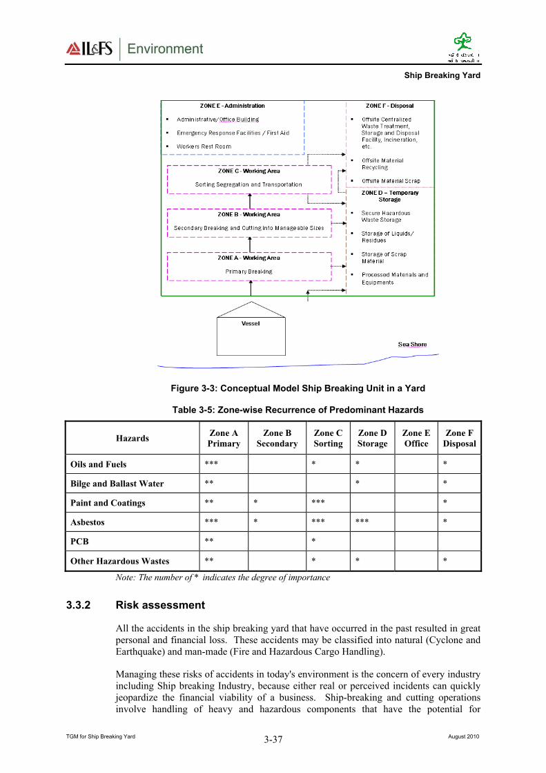
Ship Breaking Yard
TGM for Ship Breaking Yard August 2010 3-37
Figure 3-3: Conceptual Model Ship Breaking Unit in a Yard
Table 3-5: Zone-wise Recurrence of Predominant Hazards
Hazards Zone A
Primary
Zone B
Secondary
Zone C
Sorting
Zone D
Storage
Zone E
Office
Zone F
Disposal
Oils and Fuels *** * * *
Bilge and Ballast Water ** * *
Paint and Coatings ** * *** *
Asbestos *** * *** *** *
PCB ** *
Other Hazardous Wastes ** * * *
Note: The number of * indicates the degree of importance
3.3.2 Risk assessment
All the accidents in the ship breaking yard that have occurred in the past resulted in great
personal and financial loss. These accidents may be classified into natural (Cyclone and
Earthquake) and man-made (Fire and Hazardous Cargo Handling).
Managing these risks of accidents in today's environment is the concern of every industry
including Ship breaking Industry, because either real or perceived incidents can quickly
jeopardize the financial viability of a business. Ship-breaking and cutting operations
involve handling of heavy and hazardous components that have the potential for
Ship Breaking Yard
TGM for Ship Breaking Yard August 2010 3-38
accidents, which may be catastrophic to the yard, work force, environment, or public.
The detailed description on risk assessment is discussed in chapter 4.
3.3.3 Water supply
An effective arrangement has to be made to provide and maintain adequate water supply
for the workers within the yard. The influencing factors to arrive at water supply demand
in the ship breaking yard are the number of workers, number of ships/% LDT. “Indian
Dock Workers Act” (Factories Act) can be made useful in providing drinking water to the
workers and their families efficiently.
3.3.4 Sewage
Sewage originates from household wastes, human and animal wastes, domestic portion of
ship breaking units, storm runoff, groundwater infiltration, etc. An understanding of
physical, chemical and biological characteristics of wastewater is very important for
proper design, operation and management of collection, treatment and disposal of sewage.
All these characteristics would depend on the water usage patterns in the community,
commercial contributions, weather, infiltration, etc. Volume of sewage will be calculated
by assuming that 80% of the water supplied forms sewage when the area is well-covered
by sewerage network.
3.3.5 Stormwater drainage system
The ship breaking yard generates many polluting constituents including hazardous waste
from the process which require proper collection, storage, transportation and disposal.
Therefore, a stormwater drainage system along the ship breaking yards can ensure no
washing effect of the chemicals/pollutants and also prevents possible pollution additions
to the sea. As such, each yard shall have collection pits to store the initial rainwater to
prevent pollution of coastal waters. Besides, existing creeks are also to be pitched on
sides to prevent soil erosion and to protect the local land use.
3.3.6 Bilge and ballast water collection and treatment
Removal and disposal of bilge and ballast water is found to be an important activity in the
ship breaking process which, when not conducted properly may lead to environmental
and human health hazards. Ballast water is exchanged at high seas to avoid transfer of
foreign organisms from foreign water to local ecosystem. However, the remaining ballast
water present in the ship has to be removed, which is a continuous procedure throughout
the ship breaking process. Whereas, bilge water can be assumed to be a one-time activity
of emptying for few hours/days.
Based on the characteristics of bilge and ballast water the treatment scheme can be
differed. Typically, these wastewaters may contain metals, oils, fuels, grease, chemical
contaminants, etc. Therefore the treatment scheme should be selected to remove these
contaminants. For removing dissolved and suspended contaminants from wastewater, a
multiple progressive system that chemically and electrically treats wastewater and
separates oil and other contaminants from wastewater is required. This treatment
technique requires a sump, holding tank, separating tank, ozone injection system, carbon
filters, etc. The schematic view of this treatment process is shown in Figure 3-4.

Ship Breaking Yard
TGM for Ship Breaking Yard August 2010 3-39
Wastewater received by the sump is transmitted to the holding tank where it is treated
over an extended period of time. During this process influent wastewater continues to
off-load as fast as possible. Wastewater is then pumped into oil-water separator tank
where free floating oil is allowed to rise and separates into an oil retention tank for pickup
and recycling. Remaining wastewater undergoes electro-coagulation process where
emulsions are broken down and compounds which need to be treated are created. The
electro-coagulated treated water is transferred into a retention/separation tank to allow the
contaminant particles to coalesce and separate. Making use of ozone injection system and
activated carbon filter media water is transferred to a clean water holding tank. The
carbon filter media absorbs carbon and acts as a filter for any solids present. This treated
water is re-circulated until it exits the system discharge limits for organics and metals to
meet the disposal standards.
After treatment, the treated water can be disposed off into the sea and can be used for
other purposes based on its concentration level of contaminants.
Figure 3-4: Bilge and Ballast Water Treatment Scheme
3.3.7 Municipal solid waste collection and treatment
MSW should be well segregated after collection and disposed at the facility provided. To
plan a new MSW facility the following information is required.
Expected number of ships for breaking
Quantity of solid waste generated based on population and also on per ship basis
Number of workers/population
Waste generation rate
Composition of waste
3.3.8 Hazardous waste disposal facility
Various materials historically used in the construction and operation of ships will become
hazardous wastes after its life span. Of these hazardous materials, asbestos, paints,
thermocol, PCBs, glasswool, and other substances are or major importance. These
materials will be released during ship-scraping process and therefore need an appropriate
disposal facility. The hazardous waste facility can be well planned and designed with the
availability of the following information.
Expected number of ships coming for breaking
Type of ship and corresponding expected type of hazardous waste

Ship Breaking Yard
TGM for Ship Breaking Yard August 2010 3-40
Density of waste (Refer Annexure V)
Quantities (Refer factors in Table 3-2 and 3-3) and quality of hazardous waste
Volume of Waste
Capacity of the existing hazardous waste facilities/cells, if any.
In case of any existing facilities, free volumes available
Additional incremental capacity requirement corresponding to the no. of expected
ships, for specific periods.
3.3.9 Oily waste/residues collection, treatment and disposal
Oily waste should be collected separately for proper disposal. The general practice
includes selling it to the waste oil/used oil recyclers or to use it as an auxiliary fuel in the
common incineration facility.
Proper collection and disposal shall be ensured appropriately by studying the actual
volume of the waste to be incinerated and the results may be further considered in setting
up a dedicated incinerator in the vicinity, if the sufficient quantity is expected at the ship
breaking yard. These results form the minimum cut-off capacity. The incinerator should
be designed to handle the minimum cut-off capacity including elaborated tail gas
treatment.
3.3.10 Truck parking facility
Truck parking facility can be provided for easy accessibility of vehicles for transporting
scrap and other materials and to relieve the traffic congestion around the yards. The
parking facility should have basic infrastructure like potable water, sanitation, resting,
shops, eating joints, vehicle repair shops, fuelling stations, etc., for the drivers. It should
also have accommodation for transporter companies/agents. To accommodate more
number of vehicles the trucks can be parked angularly.
3.3.11 Community development infrastructure
In every ship breaking yard, considering the welfare of the ship-breaking workers, there is
a need to establish community development infrastructure, in tune with the
recommendations of the SCMC. The following task should be taken up, to establish
proper housing facilities / township for workers and their families.
Residential tenements for families, workers hostel accommodation on twin sharing
basis and dormitory accommodation with mess facility
Township with sanitation, water supply, medical and other basic facilities may be
developed
Commercial centers for workers
One time waste removal, followed by a scheduled and systematic solid waste
collection
Collection of runoff water into drains along the roads
Sanitation facilities (toilet and wash) at available land in existing settlements
Tin shaded small commercial facilities
Street lighting
In case housing cannot be provided for a certain time period, the proposed/existing slums
could be upgraded to ensure a healthy atmosphere in the neighborhood.
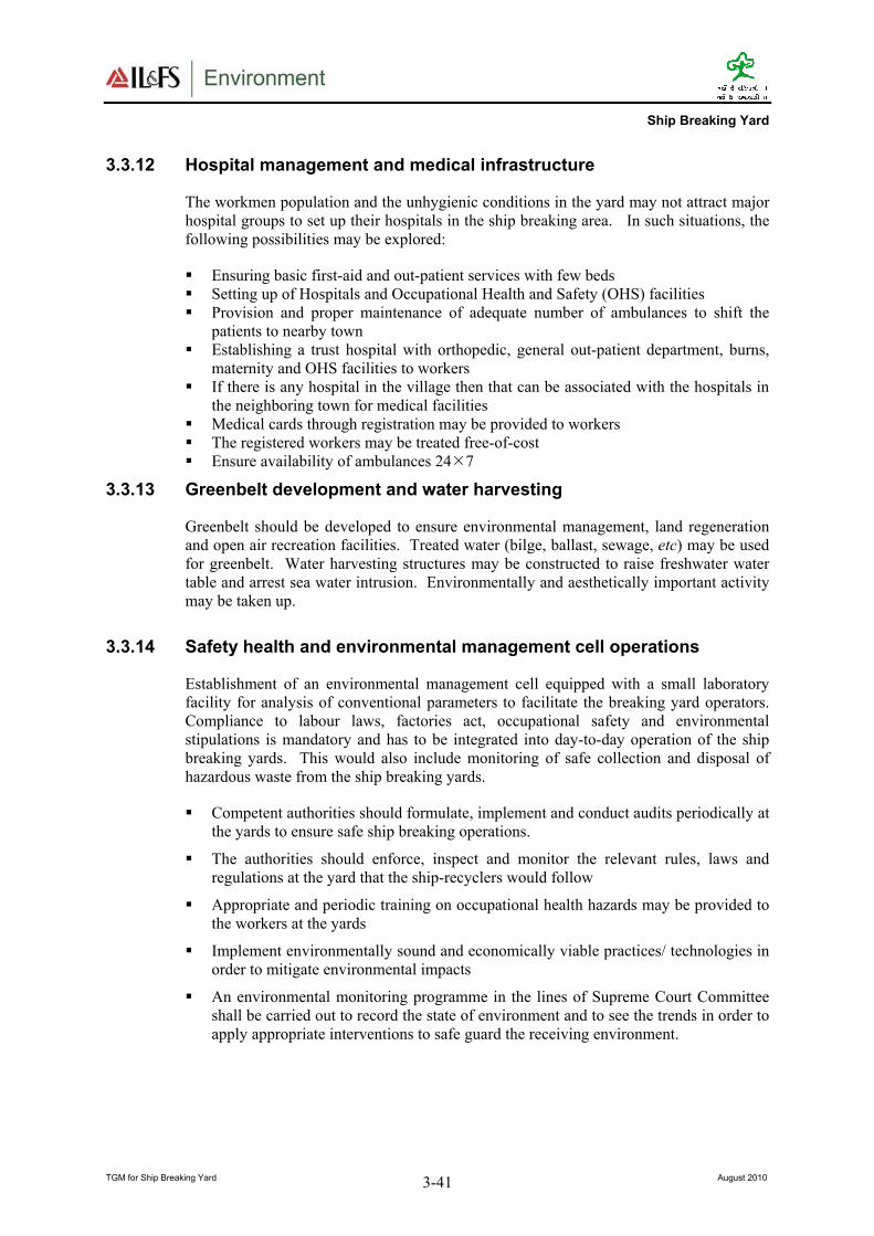
Ship Breaking Yard
TGM for Ship Breaking Yard August 2010 3-41
3.3.12 Hospital management and medical infrastructure
The workmen population and the unhygienic conditions in the yard may not attract major
hospital groups to set up their hospitals in the ship breaking area. In such situations, the
following possibilities may be explored:
Ensuring basic first-aid and out-patient services with few beds
Setting up of Hospitals and Occupational Health and Safety (OHS) facilities
Provision and proper maintenance of adequate number of ambulances to shift the
patients to nearby town
Establishing a trust hospital with orthopedic, general out-patient department, burns,
maternity and OHS facilities to workers
If there is any hospital in the village then that can be associated with the hospitals in
the neighboring town for medical facilities
Medical cards through registration may be provided to workers
The registered workers may be treated free-of-cost
Ensure availability of ambulances 24Ì7
3.3.13 Greenbelt development and water harvesting
Greenbelt should be developed to ensure environmental management, land regeneration
and open air recreation facilities. Treated water (bilge, ballast, sewage, etc) may be used
for greenbelt. Water harvesting structures may be constructed to raise freshwater water
table and arrest sea water intrusion. Environmentally and aesthetically important activity
may be taken up.
3.3.14 Safety health and environmental management cell operations
Establishment of an environmental management cell equipped with a small laboratory
facility for analysis of conventional parameters to facilitate the breaking yard operators.
Compliance to labour laws, factories act, occupational safety and environmental
stipulations is mandatory and has to be integrated into day-to-day operation of the ship
breaking yards. This would also include monitoring of safe collection and disposal of
hazardous waste from the ship breaking yards.
Competent authorities should formulate, implement and conduct audits periodically at
the yards to ensure safe ship breaking operations.
The authorities should enforce, inspect and monitor the relevant rules, laws and
regulations at the yard that the ship-recyclers would follow
Appropriate and periodic training on occupational health hazards may be provided to
the workers at the yards
Implement environmentally sound and economically viable practices/ technologies in
order to mitigate environmental impacts
An environmental monitoring programme in the lines of Supreme Court Committee
shall be carried out to record the state of environment and to see the trends in order to
apply appropriate interventions to safe guard the receiving environment.

Ship Breaking Yard
TGM for Ship Breaking Yard August 2010 3-42
3.3.15 Commercial centers
As the ship breaking yards are typically located away from the towns, the yard
management may consider building commercial and recreational facilities for their
workers within or nearer to the yard vicinity.
3.3.16 Vehicles
There should be enough number of vehicles like mobile cranes, barges, mobile asbestos
removal chambers, waste collection trucks and tankers, etc., for handling the ships and for
transportation of wastes to meet the demand of the yards. The Maritime Board can buy
such huge equipment and can supply them on a rental basis to the yard operators.
Exclusivity may be ensured by the Maritime board for sustenance and quality services in
the yard.
3.3.17 Roads
Roads are a major concern as transportation needs are high in the yard. All the scrap and
wastes which are temporarily stored in the yard have to be sent to appropriate disposal
locations like scrap to the scrap dealing market while waste and hazardous wastes must be
transported to the centralized disposal facility. The adequacy of the roads should be
ensured and feasibility studies may be carried out to arrive at the requirements.
Suitable organizations like the Maritime Board can take up the road maintenance
throughout the concession period and can get compensated by toll.
3.3.18 Firefighting infrastructure
The workers in ship breaking yard are subjected to a high risk of injury and death from
fire and explosions during ship breaking and related activities as well as firefighting
activities.
Many of the basic tasks involved in ship breaking such as welding, grinding, and cutting
metal with torches, provide an ignition source for fires. There are many combustible
materials on vessels and in ship yards, including flammable fuels, cargo, wooden
structures, building materials, and litter. The oxygen-enriched atmosphere in enclosed or
confined spaces may cause the normally fire-resistant materials to catch fire when cutting
torches are used. When fires occur, the confined or enclosed spaces of work make the
escape difficult or almost impossible for the employees working in those areas. Fire in
such confined or enclosed spaces may also result in atmospheres of combustible gases,
toxic fumes, or oxygen-depleted air.
Workers in the ship breaking yards, therefore, face risk from fire, explosions, toxic gases,
and fume that can result in burns, death, and asphyxia. Employees are also at special risk
when fighting fires in ship breaking yards. Fighting fires at landside facilities in
shipyards can be similar to traditional firefighting at typical industrial manufacturing
facilities.
Firefighting on board is considerably different from structural firefighting. When
traditional structural firefighting techniques are used on a vessel fire, the result can be
ineffective and even catastrophic. The potential is much greater for serious injury to
Ship Breaking Yard
TGM for Ship Breaking Yard August 2010 3-43
firefighting personnel when tactics do not reflect the unique nature of firefighting on
ships.
It is important for the ship breaking yards to not only have a yard-specific Fire Safety
Plan but also to have fire department trained adequately to handle on-vessel fires and fire
accidents occurring in confined spaces.
The plan must provide for the routine inspection, maintenance, and replacement of this
equipment and mandate training for new workers and refresher training for all shipyard
employment workers. The plan must include procedures for the control of fire hazards,
such as flammable and non-flammable compressed gases, ignition sources, combustible
materials, welding and hot work operations, and must include procedures for evacuation.
Training programmes on fire prevention and emergency responses to fires in ship
breaking yard and ships should be formulated in consultation with the Maritime Board
and State Fire Department and the Directorate General, factory Advice Service and
Labour Institutes (DGFASLI) and the District Administration.
3.3.19 Training infrastructure development and organizing capacity building and certification courses
The ship breaking yards must have training institutes and the workers must be trained on
various topics regularly. However, assessment on organizing trainings at different skill
levels of the personnel is essential. Very important factor in this respect is to include the
hands-on training and certification procedures.
It is also important that the workmen in crucial operations require training at regular
intervals to ensure their effectiveness and also safety and health.
It is necessary to enhance the training infrastructure and organize knowledge
development, skill development and the hands on training programmes for various target
groups on the lines of ship breaking activities.
3.4 Summary of Applicable National Regulations
Codification of national & international laws/guidelines relating to ship breaking
activities (SCMC) is annexed in Annexure VI A.
A comprehensive list of legal instruments applicable to ship breaking yard is annexed as
Annexure VI B.
Also, the enforcing agencies based on each of the ship breaking activities are annexed in
Annexure VI C.
3.4.1 General standards for discharge of environmental pollutants
List of general standards for discharge of environmental pollutants as per CPCB is given
in Annexure V.
Ship Breaking Yard
TGM for Ship Breaking Yard August 2010 3-44
3.4.2 Specific requirements
Asbestos concentrations
The permissible exposure limit (PEL) for fibre depends upon the type of asbestos. As per
landmark Supreme Court judgment on Asbestos, Supreme Court directed to appoint a
Committee of Experts to review the permissible exposure limit of 2 fibres per cubic
centimetre (f/cm3) and reduce it to 1 f/cm3 for chrysotile, 0.5 f/cm3 for amosite and for the
time being 0.2 f/cm3 for crocidolite type of fibres at par with International Standards.
The facility must ensure that workers are not exposed to airborne asbestos concentrations
in excess of either of the following limits.
0.1 f/cm3 of air averaged over an eight-hour work shift. This PEL is called the time-
weighted average (TWA) limit
1.0 f/cm3 of air averaged over a sampling period of 30 minutes. This PEL is called
the excursion limit.
PCB concentrations
Facility must ensure that workers are protected from exposure to airborne PCB
concentrations. As per OSHA (Occupational Safety and Health Administration)
regulations, governing exposure to PCBs in the workplace include two time-weighted
averages for chlorodiphenyl. These are:
1.0 mg/m3 of workplace air over an eight-hour work shift for chlorodiphenyl
containing 42% chlorine.
0.5 mg/m3 of workplace air over an eight-hour work shift for chlorodiphenyl
containing 54% chlorine.
A worker’s exposure to PCBs in any eight-hour work shift of a 40-hour week cannot
exceed these concentrations.
Paints
During paint removal activities, the facility must ensure that workers are not exposed to
any listed contaminant in excess of the PELs. For lead, which is commonly found in
paint, the PEL is 50 Fg/m3 of air averaged over an eight-hour work day. The action level
is 30 Fg/m3 of air, also based on an eight-hour work day. The action level triggers several
requirements such as exposure monitoring, medical surveillance, and training and
education.
Bilge and ballast water
The liquids, oils and fuels which are collected during ship breaking process and treated
shall meet treated effluent standards as provided by CPCB.
Table 3-6: Treated Effluent Standards as per CPCB
S.No. Parameter Standard
Land for irrigation Marine / Coastal Areas

Ship Breaking Yard
TGM for Ship Breaking Yard August 2010 3-45
S.No. Parameter Standard
Land for irrigation Marine / Coastal Areas
1 Colour and odour
All efforts should be made
to remove colour and
unpleasant odour as far as
practicable
All efforts should be made
to remove colour and
unpleasant odour as far as
practicable
2 Suspended Solids mg/l,
max
200
3 Particle size of Suspended
solids
- Floatable solids max. 3
mm
Settleable solids max. 856
microns
4 pH value 5.5 to 9.0 5.5 to 9.0
5 Temperature Shall not exceed 5°C
above receiving water
temperature
6 Oil & Grease mg/l, max 10 20
7 Total residual Chlorine
mg/l, max
- 1.0
8 Ammonical Nitrogen (as
N) mg/l, max
- 50
9 Total Kjeldhal Nitrogen
(as N) mg/l, max
- 100
10 Free Ammonia (as NH3)
mg/l, max
- 5.0
11 Biochemical Oxygen
Demand (3 days at 27°C),
mg/l, max
100
12 Chemical Oxygen
Demand mg/l, max
Not mentioned 250
13 Arsenic (as As) mg/l, max 0.2 0.2
14 Mercury (as Hg) mg/l,
max
- 0.01
15 Lead (as Pb) mg/l, max - 2.0
16 Cadmium (as Cd) mg/l,
max
- 2.0
17 Hexavalent Chromium (as
Cr+6) mg/l, max
- 1.0
18 Total Chromium (as Cr)
mg/l, max
- 2.0
19 Copper (as Cu) mg/l, max - 3.0
20 Zinc (as Zn) mg/l, max - 15
21 Selenium (as Se) mg/l,
max
0.05
22 Nickel (as Ni) mg/l, max 5.0
23 Cyanide (as CN) mg/l,
max
0.2 0.2
24 Fluoride (as F) mg/l, max - 15
25 Sulphide (as S) mg/l, max - 5.0
26 Phenolic compounds (as
C6H5OH) mg/l, max
5.0
27 Radioactive materials
(a) Alpha emitters micro
curie mg/l max
10-8 10-7

Ship Breaking Yard
TGM for Ship Breaking Yard August 2010 3-46
S.No. Parameter Standard
Land for irrigation Marine / Coastal Areas
(b) Beta emitters micro
curie mg/l max
10-7 10-6
28 Bio Assay Test 90% survival of fish after 96
hours in 100% effluent
90% survival of fish after
96 hours in 100% effluent
29 Manganese - 2 mg/l
30 Iron (as Fe) - 3 mg/l
31 Vanadium (as V) - 0.2 mg/l
32 Nitrate Nitrogen - 20 mg/l
3.4.3 Pending & proposed regulatory requirements
Central government has published steel and steel products order 2007 in a recent
notification and 17 steel products used for power distribution, health and safety,
infrastructure and construction and storage and cooking of food products are brought
under mandatory product certification.
3.4.3.1 Code of practice for ship breaking
Ministry of Steel is framing code of practice for Ship Breaking Industry as per the
directive of Honorable Supreme Court.

Operational Aspects of EIA
TGM for Ship Breaking Yard August 2010 4-1
4. OPERATIONAL ASPECTS OF EIA
Prior environmental clearance process has been revised in the Notification issued on 14th
September, 2006, into following four major stages i.e., screening, scoping, public
consultation and appraisal. Each stage has certain procedures to be followed. This
section deals with all the procedural and technical guidance, for conducting objective-
oriented EIA studies, their review and decision-making. Besides, the Notification also
classifies projects into Category A and Category B which requires prior environmental
clearance from the MoEF and SEIAA/UTEIAA respectively.
Consistency with other requirements
Clearance from other regulatory bodies is not a pre-requisite for obtaining the prior
environmental clearance and all such clearances will be treated as parallel statutory
requirements.
Consent for establishment (CFE) and prior environmental clearance are two different
legal requirements, a project proponent should acquire. Therefore, these two
activities can be simultaneously initiated and proceeded with. The project proponent
is required to take separate CRZ clearances from the concerned Authorities.
Rehabilitation and resettlement (R&R) issues need not be dealt under the EIA
Notification as other statutory bodies deal with these issues. However, socio-
economic studies be considered while taking environmental decisions.
4.1 Coverage of Ship Breaking Yards under the Purview of Notification
All new ship breaking yard projects including expansion and modernization of existing
yard requires prior environmental clearance. Based on pollution potential, all these
projects are classified into Category A
The sequence of steps in the process of prior environmental clearance for Category A
projects is shown in Figure 4.1. Each stage in the process of prior environmental
clearance for the ship breaking yards is discussed in subsequent sections. The timelines
indicated against each stage are the maximum permissible time lines set in the
Notification for said task. In case the said task is not cleared/objected by the concerned
Authority, within the specified time, said task is deemed to be cleared, in accordance to
the proposal submitted by the proponent.
In case of Expansion or Modernization of the developmental Activity:
Any ship breaking yard, which was issued EIA clearance (existing project), when
undergoes expansion or modernization with increase in ship breaking capacity in
respect of LDT of specific type of ships (such as war ships, oil tankers, cargo ships,
etc.) as per issued clearance is required to submit new application for EIA clearance.
Any change in LDT of specific type of ships in an existing ship breaking yard.
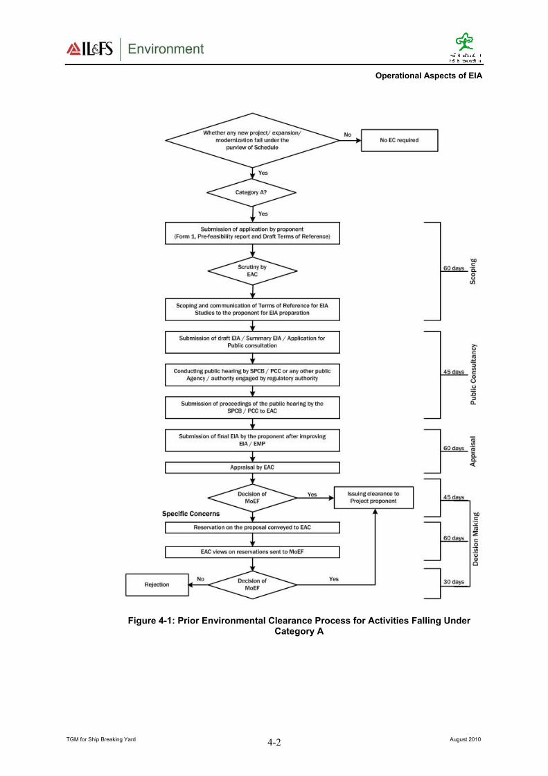
Operational Aspects of EIA
TGM for Ship Breaking Yard August 2010 4-2
Figure 4-1: Prior Environmental Clearance Process for Activities Falling Under Category A
Operational Aspects of EIA
TGM for Ship Breaking Yard August 2010 4-3
4.1.1 Application for prior environmental clearance
The project proponent, after identifying the site and carrying out a pre-feasibility
study, is required to apply for the prior environmental clearance using Form 1 given
in Annexure VII. The proponent has to submit the filled in Form 1 along with the
pre-feasibility report and draft ToR for EIA studies to the concerned Authority i.e.,
the MoEF. Please refer subsequent sections for the information on how to fill the
Form 1, contents of pre-feasibility report draft ToR for ship breaking yard.
Prior environmental clearance is required before starting any construction work, or
preparation of land on the identified site/project or activity by the project
management, except for securing the land.
If the application is made for a specific developmental activity, which has an inherent
area development component as a part of its project proposal and the same project
also attracts the construction and area development provisions under 8a and 8b of the
Schedule, then the project will be seen as a developmental activity other than 8a and
8b of the Schedule.
4.2 Scoping for EIA Studies
Scoping exercise is taken up soon after the project contours are defined. The primary
purpose of scoping is to identify the concerns and issues which may affect the project
decisions. Besides, scoping defines the requirements and boundaries of an EIA study.
Scoping refers to the process by which the EAC, including applications for expansion
and/or modernization of existing projects, determine ToR for EIA studies addressing all
relevant environmental concerns for preparation of an EIA Report for a particular project.
Project proponent shall submit application (Form 1, pre-feasibility report and
proposed ToR for EIA studies) to the MoEF. The MoEF consults the EAC to reply to
the proponent. The EAC reviews the application form, pre-feasibility report and
proposed draft ToR by the proponent and make necessary additions/deletions to make
it a comprehensive ToR that suits the statutory requirements for conducting the EIA
studies.
− Pre-feasibility report provides a precise summary of project details and also the
likely environmental concerns based on secondary information, which will be
availed for filling the Form 1.
− From pre-feasibility report and Form 1, valued environmental components
(VECs) may be identified for a given project (receiving environment/social
components, which are likely to get affected due to the project
operations/activities).
− Once the project details from the pre-feasibility report & Form 1; and VECs are
identified, a matrix establishing the interactions which can lead to the
effects/impacts could be developed (Qualitative analysis).
− For each identified possible effect in the matrix, significance analysis could be
conducted to identify the impacts, which need to be further studied (quantitative
analysis) in subsequent EIA studies. All such points will find a mention in the
draft ToR to be proposed by the project proponent along with the application
form. The draft ToR shall include applicable baseline parameters (refer annexure
X) and impact prediction tools (refer annexure XII) proposed to be applied.

Operational Aspects of EIA
TGM for Ship Breaking Yard August 2010 4-4
− The information to be provided in pre-feasibility report, guidelines for filling
Form 1 and guidelines for developing draft ToR is summarized in the subsequent
sections.
− Authority consults the respective EAC to reply to the proponent. The EAC
reviews the application form, pre-feasibility report and proposed draft ToR by the
proponent and make necessary additions/deletions to make it a comprehensive
ToR that suits the statutory requirements for conducting the EIA studies.
The concerned EAC may constitute a sub-committee for a site visit , if considered
necessary. The sub-committee will act up on receiving a written approval from
Chairperson of EAC concerned. Project proponent will facilitate such site visits of
the sub-committee.
EAC shall provide an opportunity to the project proponent for presentation and
discussions on the proposed project and related issues as well as the proposed ToR for
EIA studies. If the State Government desires to present its views on any specific
project in the scoping stage, it can depute an officer for the same at the scoping stage
to EAC, as an invitee but not as a member of EAC. However, non-appearance of the
project proponent before EAC at any stage will not be a ground for rejection of the
application for prior environmental clearance.
If a new or expansion project is proposed in a problem area as identified by the
CPCB, the MoEF may present their views, if any at the stage of scoping, to the EAC.
The final set of ToR for EIA Studies shall be conveyed to the proponent by the EAC
within sixty days of the receipt of Form 1 and pre-feasibility report. If the finalized
ToR for EIA studies is not conveyed to the proponent within sixty days of the receipt
of Form 1, the ToR suggested by the proponent shall be deemed as final and approved
for EIA studies.
Final ToR for EIA Studies shall be displayed on MoEF website.
Applications for prior environmental clearance may be rejected by the concerned
Authority based on the recommendations by the EAC at the scoping stage itself. In
case of such rejection, the decision along with the reasons for rejection shall be
communicated to the proponent in writing within sixty days of the receipt of the
application.
The final EIA report and other relevant documents submitted by the applicant shall be
scrutinized by the MoEF strictly with reference to the approved ToR for EIA studies.
4.2.1 Pre-feasibility report
The pre-feasibility report should include, but may not be limited to highlights of the
proposed project information, considering the environmental sensitivities of the selected
site, technology options, efficiency, availability, etc.
Purpose of the pre-feasibility studies
Facilitates potential entrepreneurs in project identification for investment in ship
breaking
Forms the basis for important decision-making
Provides overview of driving mechanisms of ship breaking yard
Operational Aspects of EIA
TGM for Ship Breaking Yard August 2010 4-5
Explains the dynamics of equilibrium of supply and demand of ships for the
scrapping market
Projects future volumes of ship scrapping under different scenarios based on
historical developments
Environmental information in pre-feasibility report
The information required in pre-feasibility report varies from case-to-case even in the
same sector depending upon the local environmental setting within which the ship
breaking unit is located. However, the environmental information required in the pre-
feasibility report may include:
Description of the project, including in particular:
− description of the physical characteristics of the whole project and the land-use
requirements during the operational phases
− description of the main characteristics of the scrap materials for sale
− an estimate by type and quantity, of expected residues and emissions (water, air
and soil pollution, noise, vibration, light, heat, radiation, etc.) resulting from the
operation of the proposed project. Estimate of net residue and emissions after the
installation of the proposed measures to reduce them
An outline of the main alternatives studied by the developer and an indication of the
main reasons for this choice, taking into account the environmental effects.
A description of the aspects of the environment likely to be significantly affected by
the proposed project, including, population, fauna, flora, soil, water, air, climatic
factors, material assets, architectural and archaeological heritage, landscape and the
inter-relationship between the above factors.
A description of the likely significant effects of the proposed project on the
environment resulting from:
− the existence of the project
− the emission of pollutants, nuisance creation, elimination of waste, and the
description by the developer of the forecasting methods used to assess the effects
on the environment.
A description of the measures envisaged to prevent, reduce and where possible offset
any significant adverse effects on the marine and terrestrial environment.
A non-technical summary of the information provided under the above headings.
An indication of any difficulties (technical deficiencies or lack of know-how)
encountered by the developer in compiling the required information.
Besides, depending on the scope defined in the pre-feasibility report some pre-feasibility
reports are based on various studies and data collection and addresses in detail the
concern as technical & economical analysis and detailed feasibility level design of
equipment, process optimization, transportation of products, economic, financial, social
and environmental investigations, cost estimates with detailed bill of quantities (BOQ).
The components identified here focuses on the requirements of Scoping for EIA study.
Points which may be covered in pre-feasibility report are listed in Annexure VIII.

Operational Aspects of EIA
TGM for Ship Breaking Yard August 2010 4-6
4.2.2 Guidance for Filling Information in Form 1
The information given in specifically designed pre-feasibility report for this
developmental activity may also be availed for filling Form 1.
Form 1 is designed to help users identify the likely significant environmental effects of
proposed projects during right at the scoping stage. There are two stages for providing
information under two columns:
First - identifying the relevant project activities from the list given in column 2 of
Form 1. Start with the checklist of questions set out below and complete Column 3
by answering:
– Yes - if the activity is likely to occur during implementation of the project;
– No - if it is not expected to occur;
– May be - if it is uncertain at this stage whether it will occur or not.
Second – For each activity for which the answer in Column 3 is “Yes” the next step is
to refer to the fourth column which quantifies the volume of activity which could be
judged as significant impact on the local environmental characteristics, and identify
the areas that could be affected by that activity during construction /operation /
decommissioning of the project. Form 1 requires information within 15 km around
the project, whereas actual study area for EIA will be as prescribed by respective
EAC. Project proponent will need information about the surrounding VECs in order
to complete this Form 1.
4.2.3 Identification of appropriate valued environmental components
VECs are components of ecosystems, human health, and environmental welfare
considered to be important and potentially at risk from human activity especially
concerning this project. Value may be attributed for economic, social, environmental,
aesthetic or ethical reasons. VECs represent the investigative focal point for further EIA
process. The indirect and/or cumulative effects can be concerned with indirect, additive
or even synergistic effects due to other projects or activities or even induced
developments on the same environmental components as would be considered direct
effects. But such impacts tend to involve larger scale VECs such as within entire region,
river basins or watersheds; and, broad social and economic VECs such as quality of life
and the provincial economy. Once VECs are identified then appropriate indicators may
be selected to carry on impact assessments on the respective VECs.
4.2.4 Methods for identification of impacts
There are various factors which influence the approach adopted for the assessment of
direct, indirect, cumulative impacts, etc., for a particular project. The method should be
practical and suitable for the project given the data, time and financial resources available.
However, the method adopted should be able to provide a meaningful conclusion from
which it would be possible to develop, where necessary, mitigation measures and
monitoring. Key points to consider when choosing the method(s) include:
Nature of the impact(s)
Availability and quality of data
Availability of resources (time, finance and staff)

Operational Aspects of EIA
TGM for Ship Breaking Yard August 2010 4-7
The method chosen should not be complex, but should aim at presenting the results in a
way that can be easily understood by the developer, decision maker and the public. A
comparative analysis of major impact identification methods is given in table 4-1.
Table 4-1: Advantages and Disadvantages of Impact Identification Methods
Description Advantages Disadvantages
Checklists Annotate the
environmental features that
need to be addressed when
identifying the impacts of
activities in the project
Simple to
understand and
use
Good for site
selection and
priority setting
Simple ranking
and weighting
Do not distinguish
between direct
and indirect
impacts
Do not link action
and impact
The process of
incorporating
values can be
controversial
Matrices Identify the interaction
between project activities
(along one axis) and
environmental
characteristics (along other
axis)using a gird like table
Entries are made in the
cells which highlights
impact severity in the form
of symbols or numbers or
descriptive comments
Link action to
impact
Good method for
displaying EIA
results
Difficult to
distinguish direct
and indirect
impacts
Significant
potential for
double-counting
of impacts
Networks Illustrate cause effect
relationship of project
activities and
environmental
characteristics
Useful in identifying
secondary impacts
Useful for establishing
impact hypothesis and
other structured science-
based approaches to EIA
Link action to
impact
Useful in
simplified form
for checking for
second order
impacts
Handles direct
and indirect
impacts
Can become very
complex if used
beyond simplified
version
Overlays Map the impacts spatially
and displays them
pictorially
Useful for comparing site
and planning alternatives
for routing linear
developments
Can address cumulative
effects
Information incentive
Easy to
understand
Good to display
method
Good siting tool
Addresses only
direct impacts
Does not address
impact duration or
probability
GIS
(Geographical
Information
Systems)
Maps the impacts spatially
and display s them
pictorially
Useful for comparing site
and planning alternatives
for routing linear
developments
Easy to
understand
Good to display
method
Good siting tool
Excellent for
impact
Do not address
impact duration or
probability
Heavy reliance on
knowledge and
data
Often complex

Operational Aspects of EIA
TGM for Ship Breaking Yard August 2010 4-8
Description Advantages Disadvantages
Can address cumulative
effects
Information incentive
identification and
analysis
and expensive
Expert
System
Assist diagnosis, problem
solving and decision
making
Collects inputs from user
by answering
systematically developed
questions to identify
impacts and determine
their mitigability and
significance
Information intensive, high
investment methods of
analysis
Excellent for
impact
identification and
analysis
Good for
experimenting
Heavy reliance on
knowledge and
data
Often complex
and expensive
The Project Team made an attempt to construct an impact matrix considering major
project activities (generic operations) and stage-specific likely impacts which is given in
Table 4-2.
While the impact matrix is project-specific, Table 4-2 may facilitate the stakeholders in
identifying a set of components and phase-specific project activities for determination of
likely impacts. Location-specific concerns may vary from case to case. Therefore, the
components even without likely impacts are also retained in the matrix for the location-
specific reference.
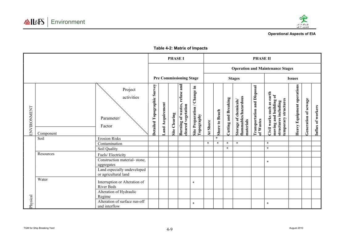
Operational Aspects of EIA
TGM for Ship Breaking Yard August 2010 4-9
Table 4-2: Matrix of Impacts
PHASE I PHASE II
Operation and Maintenance Stages
Pre Commissioning Stage Stages Issues
EN
VIR
ON
ME
NT
Component
Det
ail
ed T
op
ogra
ph
ic S
urv
ey
La
nd
Acq
uir
emen
t
Sit
e C
leari
ng
Bu
rnin
g o
f w
ast
es, re
fuse
an
d
clea
red
veg
etati
on
Sit
e P
rep
ara
tio
n /
Ch
an
ge
in
To
pog
rap
hy
At
Sh
ore
Sh
ore
to
Bea
ch
Cu
ttin
g a
nd
Bre
ak
ing
Sto
rag
e o
f ch
emic
als
/
fla
mm
ab
les/
ha
zard
ou
s
ma
teri
als
Tra
nsp
ort
ati
on
an
d D
isp
osa
l
of
Wa
stes
Civ
il w
ork
s su
ch a
s ea
rth
mov
ing a
nd
bu
ild
ing
of
stru
ctu
res
incl
ud
ing
tem
po
rary
str
uct
ure
s
Hea
vy E
qu
ipm
ent
op
erati
on
s
Gen
erati
on
of
sew
age
Infl
ux o
f w
ork
ers
Erosion Risks *
Contamination * * * * *
Soil
Soil Quality * *
Fuels/ Electricity
Construction material- stone,
aggregates *
Resources
Land especially undeveloped
or agricultural land
Interruption or Alteration of
River Beds *
Alteration of Hydraulic
Regime
Physi
cal
Water
Alteration of surface run-off
and interflow * *
Parameter/
Factor
Project
activities
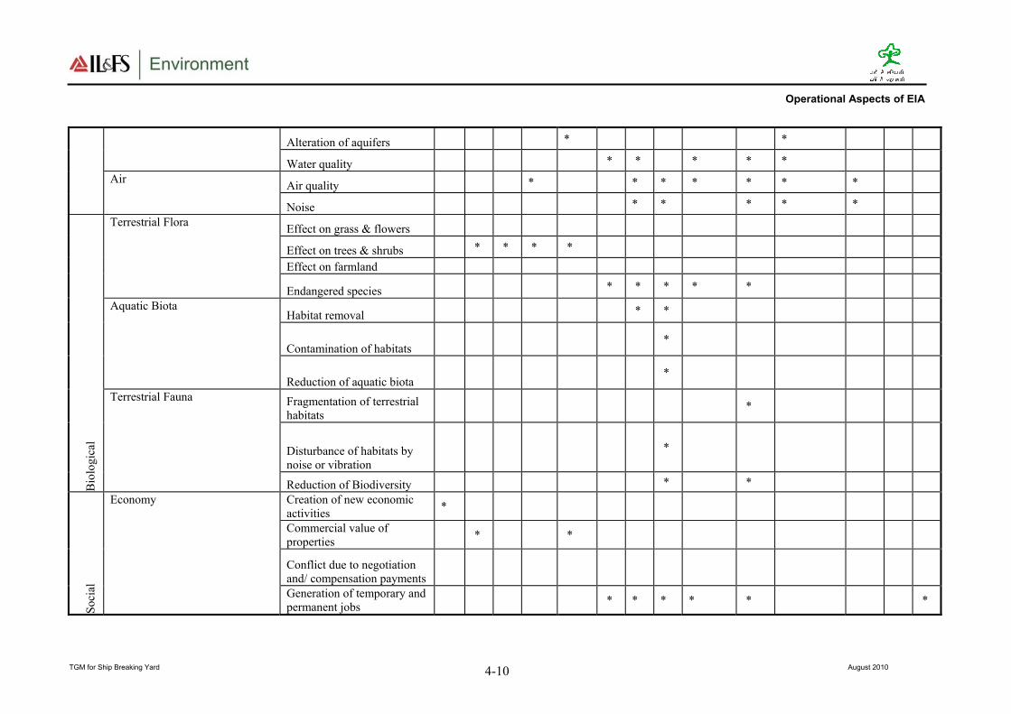
Operational Aspects of EIA
TGM for Ship Breaking Yard August 2010 4-10
Alteration of aquifers * *
Water quality * * * * *
Air quality * * * * * * * Air
Noise * * * * *
Effect on grass & flowers
Effect on trees & shrubs * * * *
Effect on farmland
Terrestrial Flora
Endangered species * * * * *
Habitat removal * *
Contamination of habitats *
Aquatic Biota
Reduction of aquatic biota *
Fragmentation of terrestrial
habitats *
Disturbance of habitats by
noise or vibration
*
Bio
log
ical
Terrestrial Fauna
Reduction of Biodiversity * *
Creation of new economic
activities *
Commercial value of
properties * *
Conflict due to negotiation
and/ compensation payments
Soci
al
Economy
Generation of temporary and
permanent jobs * * * * * *

Operational Aspects of EIA
TGM for Ship Breaking Yard August 2010 4-11
Effect on crops * * *
Reduction of farmland
productivity *
Income for the state and
private sector * * *
Training in new technologies * * *
Education
Training in new skills to
workers * * * * *
Political Conflicts * * * * * * Public Order
Unrest, Demonstrations &
Social conflicts * *
Infrastructure and Services Conflicts with projects of
urban, commercial or
Industrial development
* * * * * * * * * * * * * *
Increase in Crime * * Security and Safety
Accidents caused * * * * *
Health * * * * *
Land use * *
Recreation *
Aesthetics and human
interest * * * * *
Cultural
Cultural status *
Note:
1. The above table represents a model for likely impacts, which will have to be arrived case-to-case basis considering VECs and significance analysis (Ref
Section. 2.9).
2. Project activities are shown as indicative. However, in Form 1 (application for EIA Clearance), for any question for which answer is ‘Yes’, then the
corresponding activity shall reflect in project activities. Similarly ‘parameters’/’factors’ will also be changed within a component in order to reflect the target
species of prime concern in the receiving local environment.
Operational Aspects of EIA
TGM for Ship Breaking Yard August 2010 4-12
4.2.5 Testing the significance of impacts
The following set of conditions may be used as the checklist for testing the significance of
the impacts and also to provide information in Column IV of Form 1.
Will there be a large change in environmental conditions?
Will new features be out-of-scale with the existing environment?
Will the effect be unusual in the area or particularly complex?
Will the effect extend over a large area?
Will there be any potential for trans-frontier impact?
Will many people be affected?
Will many receptors of other types (fauna and flora, businesses, facilities) be
affected?
Will valuable or scarce features or resources be affected?
Is there a risk that environmental standards will be breached?
Is there a risk that protected sites, areas, features will be affected?
Is there a high probability of the effect occurring?
Will the effect continue for a long time?
Will the effect be permanent rather than temporary?
Will the impact be continuous rather than intermittent?
If it is intermittent will it be frequent rather than rare?
Will the impact be irreversible?
Will it be difficult to avoid, or reduce or repair or compensate for the effect?
For each ‘Yes’ answer in column 3, the nature of effects and reasons for it should be
recorded in column 4. The questions are designed so that the ‘Yes’ answer in column 3,
will generally point towards the need for analyzing for the significance and requirement
for conducting impact assessment for the effect.
4.2.6 Terms of reference for EIA studies
Ship breaking yard refers to group of individual ship breaking units. The expert
committee suggested to consider only ship breaking yards for the purpose of EIA studies
and thus this ToR is for ship breaking yards. ToR for EIA studies w.r.t ship breaking
yards may include, but not limited to following:
Executive summary of the project - giving a prima facie idea of the objectives of the
proposal, use of resources, justification, etc. In addition, it should provide a
compilation of EIA report including EMP and the post-project monitoring plan in
brief.
Project description
Backward and forward linkages of the project – sale and purchase of ships for
scrapping, demand for scrapping, scrap market, availability of re-rolling mills, etc.
Proposed ship dismantling plan and facilities management plan.
Details of temporary storage facilities for wastes and scrap from vessels in the yard –
storage for asbestos, PCBs, radioactive wastes, gas cylinders, administrative office
building, workers’ rest/changing room, storage facility for bilge and ballast water,
storage facility for oil residues.
Injuries, accidents and possible hazards during the ship breaking process.
Operational Aspects of EIA
TGM for Ship Breaking Yard August 2010 4-13
List of proposed personal protective equipments to be provided to safeguard health
and safety of workers.
Details of local amenities and infrastructural developmental activities - electricity,
drinking water facilities, sewage facilities, roads, transportation, communication,
housing, greenbelt.
Details of the transportation system from the yard and the traffic density.
Details of the provisions for treatment or disposal of all types of wastes generated by
the ship breaking yard (locations and capacities of the provisions for hazardous waste,
solid waste, radioactive waste, asbestos, etc.)
Details regarding infrastructure facilities such as sanitation, fuel storage rooms,
restrooms, etc. to be provided to the workmen during ship breaking operations.
Any litigation pending against the project and /or any direction /order passed by any
Court of Law related to the environmental pollution and impacts in the last two years,
if so, details thereof.
In case of expansion projects, compliance to the issued EIA clearance conditions and
consent for operation conditions for existing yard.
Description of the environment
The study area shall be up to a distance of 5 km from the boundary of the proposed
ship breaking yard.
Geographic information of the site – Latitude/Longitude, total area envisaged for
setting up of the industry, seismic zone classification.
Landuse of the proposed project area – notified industrial area, grazing, mangroves,
no development area, national parks, sanctuary, marshes, fishing area, etc.
Landuse of study area should also include data about the residential/institutional/
nearest village/township/locality/housing society, etc., based on the satellite imagery.
Topography details of the project area.
The baseline data to be collected from the study area w.r.t. different components of
environment viz. air, noise, water, land, and biology and socio-economic (please refer
Section 4.4.2 for guidance for assessment of baseline components and identify
attributes of concern). Actual monitoring of baseline environmental components shall
be strictly according to the parameters prescribed in the ToR after considering the
proposed coverage of parameters by the proponent in draft ToR and shall commence
after finalization of ToR by the competent Authority.
Details of site and information related to environmental setting within a 5 km radius
on the landward side – CRZ classification, LTL, HTL (High Tide Line), bathymetric
survey.
CRZ map in 1:10000 scale in general cases and in 1:5000 scale for specific
observations.
Environmental parameters – temperature, sea level pressure, wind speed, mean
relative humidity, visibility, salinity, density, rainfall, fog, frequency and intensity of
cyclones, sediment transport, seismic characteristics, fresh water influx.
Details on marine biological parameters – microbiological population, pathogenic
bacteria, plankton distribution, fish spawning grounds in the adjoining waters,
commercial fishery potential, vegetation including intertidal flora and fauna in the
Operational Aspects of EIA
TGM for Ship Breaking Yard August 2010 4-14
marine, benthal quality assessment for biological species and heavy metals and
estuarine environment.
Site-specific meteorological data of one season.
Source of water and its availability. Proof regarding the availability of requisite
quantity of water from the competent Authority.
Details of groundwater quality around the industry – groundwater samples to be
collected from 7 to 10 locations.
Details of stormwater management.
Details on water quality parameters such as Temperature, pH , Colour, TDS, BOD,
COD, N (total), Chlorides, sulphides , NH3, Fish, toxicity, Metals ( Mn, Tl, V, Sn,
Cd, Cr, Ni, Cu, Hg, Pb, Zn , etc.), PCBs, etc.
Ambient Air Quality (AAQ) data (except monsoon) of one complete season along
with the monitoring dates. The parameters to be covered shall include PM10, PM2.5,
SO2, NOx, VOCs and Asbestos. The location of the monitoring stations should be
within the proposed project area and at about 500m towards the land side.
− Dust fall shall be monitored at each AAQ.
− AAQ monitoring stations shall be located within the study area.
Noise levels monitoring at three sides surrounding the yard and at sensitive/
commercial/residential locations within the study area.
Sea water and sediments must be collected up to 500m from the site at multiple points
depending on activities at beach.
Soil sampling to be done from each AAQ station such that a relationship is developed
between dust fall and soil quality.
If any incompatible land use attributes fall within a 5 km radius of the project
boundary, proponent shall describe the sensitivity (distance, area and significance)
and propose the additional points based on significance for review and acceptance by
the EAC. Incompatible land use attributes include:
− Public water supply areas from rivers/surface water bodies, from ground water
− Scenic areas/tourism areas/hill resorts
− Religious places, pilgrim centers that attract over 10 lakh pilgrims a year
− Protected tribal settlements (notified tribal areas where industrial activity is not
permitted)
− CRZ
− Monuments of national significance, World Heritage Sites
− Cyclone, Tsunami prone areas (based on last 25 years);
− Airport areas
− Any other feature as specified by the State or local government and other features
as locally applicable, including prime agricultural lands, pastures, migratory
corridors, etc.
If ecologically sensitive attributes fall within a 5 km radius of the project boundary,
proponent shall describe the sensitivity (distance, area and significance) and propose
the additional points based on significance for review and acceptance by the EAC.
Ecological sensitive attributes include:
− National parks
− Wild life sanctuaries Game reserve
− Tiger reserve/elephant reserve/turtle nesting ground
− Mangrove area

Operational Aspects of EIA
TGM for Ship Breaking Yard August 2010 4-15
− Wetlands
− Reserved and Protected forests, etc.
− Any other closed/protected area under the Wild Life (Protection) Act, 1972, any
other area locally applicable.
Anticipated environmental impacts and mitigation measures
Anticipated environmental impacts that require specific studies for significance are
given impact matrix (Table 4-2 may be referred). Tools as given in Section 4.3.3 may
be used for the assessment of environmental impacts.
Impact on drainage of the area and the surroundings.
Impact of the project on local infrastructure within the study area such as road
network, etc.
Measures that could be considered for the mitigation of impacts.
Oil spill models may be used to predict the likely impacts, in case of eventuality.
Proposed measures for occupational safety and health of the workers.
Analysis of alternative technologies
Justification for selecting the proposed ship breaking yard (LDT, individual unit/plot
size, infrastructure – type of ships, number of ships that can be accommodated).
Comparison of alternate sites and dismantling methods (beaching, docking, berthing)
and the reasons for selecting the same. Conformity of the site with the prescribed
guidelines in terms of rivers, highways, etc.
Details on better practices.
Environmental monitoring program
Monitoring programme for pollution control at source.
Monitoring pollutants at receiving environment for the appropriate notified
parameters – air quality, groundwater, surface water, etc. during operational phase of
the project.
Specific programme to monitor safety and health protection of workers.
Appropriate monitoring network has to be designed and proposed for regulatory
compliance and to assess the residual impacts, if any.
Details of in-house monitoring capabilities and the recognized agencies if proposed
for conducting monitoring.
Additional studies
Details on risk assessment and damage control during different phases of the project
and proposed safeguard measures.
Detailed socio-economic status of the area (including migrated labor), homestead
oustees, fishermen, reduction in fishing yields, project-affected people, etc.
Proposed plan to handle the socio-economic influence on the local community. The
plan should include quantitative dimension as far as possible.
Risk assessment and mitigation measures, fire-fighting, emergency management plan
and services.
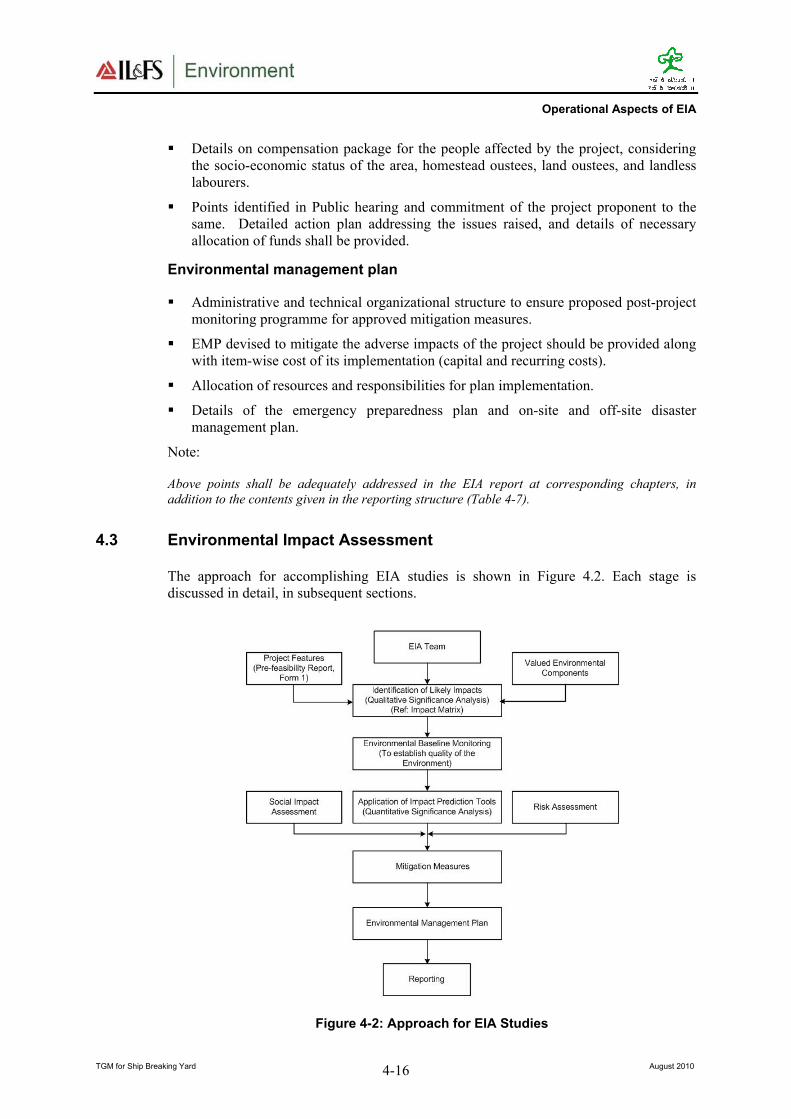
Operational Aspects of EIA
TGM for Ship Breaking Yard August 2010 4-16
Details on compensation package for the people affected by the project, considering
the socio-economic status of the area, homestead oustees, land oustees, and landless
labourers.
Points identified in Public hearing and commitment of the project proponent to the
same. Detailed action plan addressing the issues raised, and details of necessary
allocation of funds shall be provided.
Environmental management plan
Administrative and technical organizational structure to ensure proposed post-project
monitoring programme for approved mitigation measures.
EMP devised to mitigate the adverse impacts of the project should be provided along
with item-wise cost of its implementation (capital and recurring costs).
Allocation of resources and responsibilities for plan implementation.
Details of the emergency preparedness plan and on-site and off-site disaster
management plan.
Note:
Above points shall be adequately addressed in the EIA report at corresponding chapters, in
addition to the contents given in the reporting structure (Table 4-7).
4.3 Environmental Impact Assessment
The approach for accomplishing EIA studies is shown in Figure 4.2. Each stage is
discussed in detail, in subsequent sections.
Figure 4-2: Approach for EIA Studies

Operational Aspects of EIA
TGM for Ship Breaking Yard August 2010 4-17
4.3.1 EIA team
EIA is a multi-functional activity. Establishing the right team in the initial stages is
important for the success of an EIA, and also for the assessment of all significant impacts
(direct, indirect as well as cumulative impacts) associated with different environmental
resources. It would be appropriate to supplement the in-house environmental skills with
appropriate internal/external specialists to undertake assessments for certain topics or to
coordinate and oversee the project.
The professional Team identified for a specific EIA study should consist of qualified and
experienced professionals from various disciplines in order to address the critical aspects
identified for the specific project. Based on the nature and the environmental setting,
following professionals may be identified for EIA studies:
Environmental management specialist/Regulator
Air and noise quality expert
Occupational health
Geology/geo-hydrology
Ecologist
Transportation Specialist
Safety and health specialist
Social scientist
Organic chemistry
Radioactivity
Chemical engineer
Marine Biology, etc.
4.3.2 Baseline quality of the environment
EIA Notification 2006 specifies that an EIA Report should contain a description of the
existing environment that would be or might be affected directly or indirectly by the
proposed project. Environmental Baseline Monitoring (EBM) is a very important stage of
EIA. On one hand EBM plays a very vital role in EIA while on the other it provides
feedback about the actual environmental impacts of the proposed project. EBM, during
the operational phase, helps in judging the success of mitigation measures in protecting
the environment. Mitigation measures, in turn, are used to ensure compliance with
environmental standards, and to facilitate the needed project design or operational
changes.
Description of the existing environment should include natural, cultural, socio-economic
systems and their interrelationships. The intention is not to describe all baseline
conditions, but to focus the collection and description of baseline data on those VECs that
are important and are likely to be affected by the proposed ship breaking activity.
4.3.2.1 Objective of EBM in the EIA context
The term ‘baseline’ refers to conditions existing before development. EBM studies are
carried out to:
identify environmental conditions which might influence project design decisions
(e.g., site layout, structural or operational characteristics)
identify sensitive issues or areas requiring mitigation or compensation

Operational Aspects of EIA
TGM for Ship Breaking Yard August 2010 4-18
provide input data to analytical models used for predicting effects
provide baseline data against which the results of future monitoring programs can be
compared
At this stage of EIA process, EBM is primarily discussed in the context of first purpose
wherein feedback from EBM programs may be used to:
determine available assimilative capacity of different environmental components
within the designated impact zone and whether more or less stringent mitigation
measures are needed; and
improve predictive capability of EIAs.
There are many institutional, scientific, quality control, and fiscal issues that must be
addressed in implementation of an environmental monitoring program. Careful
consideration of these issues in the design and planning stages will help in avoiding many
pitfalls associated with environmental monitoring programs.
4.3.2.2 Environmental monitoring network design
Monitoring refers to the collection of data using a series of repetitive measurements of
environmental parameters (or, more generally, to a process of systematic observation).
Design of the environmental quality monitoring programme depends up on the
monitoring objectives specified for the selected area of interest. Types of monitoring and
network design considerations are discussed in Annexure IX.
4.3.2.3 Baseline data generation
List of important physical environmental components and indicators of EBM are given in
Table 4-3.
Table 4-3: List of Important Physical Environment Components
Environmental Component Environmental Indicators
Climatic variables Rainfall patterns – mean, mode, seasonality
Temperature patterns
Extreme events
Climate change projections
Relative humidity
Prevailing wind - direction, speed, anomalies
Stability conditions and mixing height, etc.
Geology Underlying rock type, texture
Geologic structures (faults, shear zones, etc.)
Geologic resources (minerals, etc.)
Topography Slope form
Landform and terrain analysis
Specific landform types, etc.
Coastal dynamics and
morphology
Wave patterns
Currents
Shoreline morphology – near shore, foreshore
Sediment – characteristics and transport, etc.
Soil Type and characteristics
Porosity and permeability
Sub-soil permeability
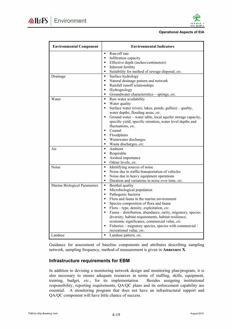
Operational Aspects of EIA
TGM for Ship Breaking Yard August 2010 4-19
Environmental Component Environmental Indicators
Run-off rate
Infiltration capacity
Effective depth (inches/centimeters)
Inherent fertility
Suitability for method of sewage disposal, etc.
Drainage Surface hydrology
Natural drainage pattern and network
Rainfall runoff relationships
Hydrogeology
Groundwater characteristics – springs, etc.
Water Raw water availability
Water quality
Surface water (rivers, lakes, ponds, gullies) – quality,
water depths, flooding areas, etc.
Ground water – water table, local aquifer storage capacity,
specific yield, specific retention, water level depths and
fluctuations, etc.
Coastal
Floodplains
Wastewater discharges
Waste discharges, etc.
Air Ambient
Respirable
Airshed importance
Odour levels, etc.
Noise Identifying sources of noise
Noise due to traffic/transportation of vehicles
Noise due to heavy equipment operations
Duration and variations in noise over time, etc.
Marine Biological Parameters Benthal quality
Microbiological population
Pathogenic bacteria
Flora and fauna in the marine environment
Species composition of flora and fauna
Flora – type, density, exploitation, etc.
Fauna – distribution, abundance, rarity, migratory, species
diversity, habitat requirements, habitat resilience,
economic significance, commercial value, etc.
Fisheries – migratory species, species with commercial /
recreational value, etc.
Landuse Landuse pattern, etc.
Guidance for assessment of baseline components and attributes describing sampling
network, sampling frequency, method of measurement is given in Annexure X.
Infrastructure requirements for EBM
In addition to devising a monitoring network design and monitoring plan/program, it is
also necessary to ensure adequate resources in terms of staffing, skills, equipment,
training, budget, etc., for its implementation. Besides assigning institutional
responsibility, reporting requirements, QA/QC plans and its enforcement capability are
essential. A monitoring program that does not have an infrastructural support and
QA/QC component will have little chance of success.

Operational Aspects of EIA
TGM for Ship Breaking Yard August 2010 4-20
Defining data statistics/analyses requirements
The data analysis to be conducted is dictated by the objectives of environmental
monitoring program. The statistical methods used to analyze data should be described in
detail prior to data collection. This is important because repetitive observations are
recorded in time and space. Besides, the statistical methods could also be chosen so that
uncertainty or error estimates in the data can be quantified. For e.g., statistical methods
useful in an environmental monitoring program include: 1) frequency distribution
analysis; 2) analysis of variance; 3) analysis of covariance; 4) cluster analysis; 5) multiple
regression analysis; 6) time series analysis; 7) the application of statistical models.
Use of secondary data
The EBM program addresses temporal and/or spatial variations limited to a certain extent
because of cost implications and time limitations. Therefore analysis of all available
information or data is essential to establish the regional profiles. So all the relevant
secondary data available for different environmental components should be collated and
analyzed.
To facilitate stakeholders, IL&FS Ecosmart Ltd., has made an attempt to compile the list
of information required for EIA studies and sources of secondary data, which are
provided in Annexure XIA, and Annexure XIB.
4.3.3 Impact prediction tools
The scientific and technical credibility of an EIA relies on the ability of EIA practitioners
to estimate the nature, extent, and magnitude of change in environmental components that
may result from project activities. Information about predicted changes is needed for
assigning impact significance, prescribing mitigation measures, designing & developing
EMPs and monitoring programs. The more accurate the predictions, the more confident
the EIA practitioner will be in prescribing specific measures to eliminate or minimize the
adverse impacts of development project.
Choice of models/methods for impact predictions in respect of each of air, noise, water,
land and biological environment are precisely tabulated in Annexure XII.
4.3.4 Significance of the impacts
Evaluating the significance of environmental effects is perhaps the most critical
component of impact analysis. More than other components, the interpretation of
significance is also a contentious process. The interpretation of significance bears direct
relation to the subsequent EIA process and also during EC on project approvals and
condition setting. At an early stage, it also enters into screening and scoping decisions
like the level of assessment required and the kind of impacts and issues to be addressed.
Impact significance is also a key to the choice of alternatives. In total, the attribution of
significance continues throughout the EIA process, from scoping to EIS review, in a
gradually narrowing “cone of resolution” in which one stage sets up the next. But at this
stage it is the most important as better understanding and quantification of impact
significance is required.
Operational Aspects of EIA
TGM for Ship Breaking Yard August 2010 4-21
One common approach is based on determination of the significance of predicted changes
in the baseline environmental characteristics and compares these with reference to the
regulatory standards, objective criteria and similar ‘thresholds’ as eco-sensitivity, cultural
/religious values. These are often outlined in guidance manuals. A better test proposed
by the CEAA (1995) is to determine if ‘residual’ environmental effects are adverse,
significant, and likely (given under). But at this stage, the practice of formally evaluating
the significance of residual impacts, i.e., after predicting the nature and magnitude of
impacts based on before-versus-after-project comparisons, and identifying measures to
mitigate these effects is not being followed in a systematic way.
Step 1: Are the environmental effects adverse?
Criteria for determining the adversity of the effects include:
effects on biota health
effects on rare or endangered species
reductions in species diversity
habitat loss
transformation of natural landscapes
effects on human health
effects on current use of lands and resources for traditional purposes by aboriginal
persons; and
foreclosure of future resource use or production
Step 2: Are the adverse environmental effects significant?
Criteria for determining ‘significance’ are to judge if the impacts:
are extensive over space or time
are intensive in concentration or proportion to assimilative capacity
exceed environmental standards or thresholds
do not comply with environmental policies, landuse plans, sustainability strategy
adversely and seriously affect ecologically sensitive areas
adversely and seriously affect heritage resources, other landuses, community lifestyle
and/or indigenous peoples traditions and values
Step 3: Are the significant adverse environmental effects likely?
Criteria for determining ‘likelihood’ include:
probability of occurrence, and
scientific uncertainty
4.4 Social Impact Assessment
Social impact assessment (SIA) is an instrument used to analyze social issues and solicit
stakeholder views for the design of projects. SIA helps in making the project responsive
to social development concerns, including options that enhance benefits for poor and
vulnerable people while mitigating risk and adverse impacts. It analyzes distributional
impacts of intended project benefits on different stakeholder groups, and identifies
differences in assets and capabilities to access the project benefits.
The scope and depth of SIA should be determined by the complexity and importance of
the issues studied, taking into account the skills and resources available. SIA should

Operational Aspects of EIA
TGM for Ship Breaking Yard August 2010 4-22
include studies related to involuntary resettlement, compulsory land acquisition, impact of
imported workforces, job losses among local people, damage to sites of cultural, historic
or scientific interest, impact on minority or vulnerable groups, child or bonded labour, use
of armed security guards. However, SIA may primarily include the following:
Description of the socio-economic, cultural and institutional profile
Conduct a rapid review of available sources of information to describe the socio-
economic, cultural and institutional interface in which the project operates.
Socio-economic and cultural profile: Describe the most significant social, economic and
cultural features that differentiate social groups in the project area. Describe their
different interests in the project, and their levels of influence. Explain any specific effects
the project may have on the poor and underprivileged. Identify any known conflicts
among groups that may affect project implementation.
Institutional profile: Describe the institutional environment; consider both the presence
and function of public, private and civil society institutions relevant to the operation. Are
there important constraints within existing institutions e.g. disconnect between
institutional responsibilities and the interests and behaviors of personnel within those
institutions? Or are there opportunities to utilize the potential of existing institutions, e.g.
private or civil society institutions, to strengthen implementation capacity.
Legislative and regulatory considerations
To review laws and regulations governing the project’s implementation and access of
poor and excluded groups to goods, services and opportunities provided by the project. In
addition, review the enabling environment for public participation and development
planning. SIA should build on strong aspects of legal and regulatory systems to facilitate
program implementation and identify weak aspects while recommending alternative
arrangements.
Key social issues
SIA provides baseline information for designing social development strategy. The
analysis should determine the key social and Institutional issues which affect the project
objectives; identify the key stakeholder groups in this context and determine how
relationships between stakeholder groups will affect or be affected by the project; and
identify expected social development outcomes and actions proposed to achieve those
outcomes.
Data collection and methodology
Describe the design and methodology for social analysis. In this regard:
Build on existing data
Clarify the units of analysis for SIA: intra-household, household level, as well as
communities/settlements and other relevant social aggregations on which data is
available or will be collected for analysis;
Choose appropriate data collection and analytical tools and methods, employing
mixed methods wherever possible; mixed methods include a mix of quantitative and
qualitative methods.
Operational Aspects of EIA
TGM for Ship Breaking Yard August 2010 4-23
Strategy to achieve social development outcomes
Identify the likely social development outcomes of the project and propose a social
development strategy, including recommendations for institutional arrangements to
achieve them, based on the findings of the social assessment. The social development
strategy could include measures that:
strengthen social inclusion by ensuring inclusion of both poor and excluded groups
as well as that intended beneficiaries are included in the benefit stream; offer access
to opportunities created by the project
empower stakeholders through their participation in design and implementation of the
project, their access to information, and their increased voice and accountability (i.e.,
a participation framework); and
enhance security by minimizing and managing likely social risks and increasing the
resilience of intended beneficiaries and affected persons to socioeconomic shocks
Implications for analysis of alternatives
Review proposed approaches for the project, and compare them in terms of their relative
impacts and social development outcomes. Consider what implications the findings of
the social assessment might have on those approaches. Should some new components be
added to the approach, or other components be reconsidered or modified?
If the SIA and consultation processes indicate that alternative approaches may have better
development outcomes, such alternatives should be described and considered, along with
the likely budgetary and administrative effects these changes might have.
Recommendations for project design and implementation arrangements
Provide guidance to project management and other stakeholders on how to integrate
social development issues into project design and implementation arrangements. As
much as possible, suggest specific action plans or implementation mechanisms to address
relevant social issues and potential impacts. These can be developed as integrated or
separate action plans, for example, as Resettlement Action Plans, Indigenous Peoples
Development Plans, Community Development Plans, etc.
Developing a monitoring plan
Through SIA process, a framework for monitoring and evaluation should be developed.
To the extent possible, this should be done in consultation with key stakeholders,
especially beneficiaries and affected people.
The framework shall identify expected social development indicators, establish
benchmarks, and design systems and mechanisms for measuring progress and results
related to social development objectives. The framework shall identify organizational
responsibilities in terms of monitoring, supervision, and evaluation procedures. Wherever
possible, participatory monitoring mechanisms shall be incorporated. The framework
should establish:
a set of monitoring indicators to track the progress achieved. The benchmarks and
indicators should be limited in number, and should combine both quantitative and
qualitative types of data. The indicators for outputs to be achieved by the social
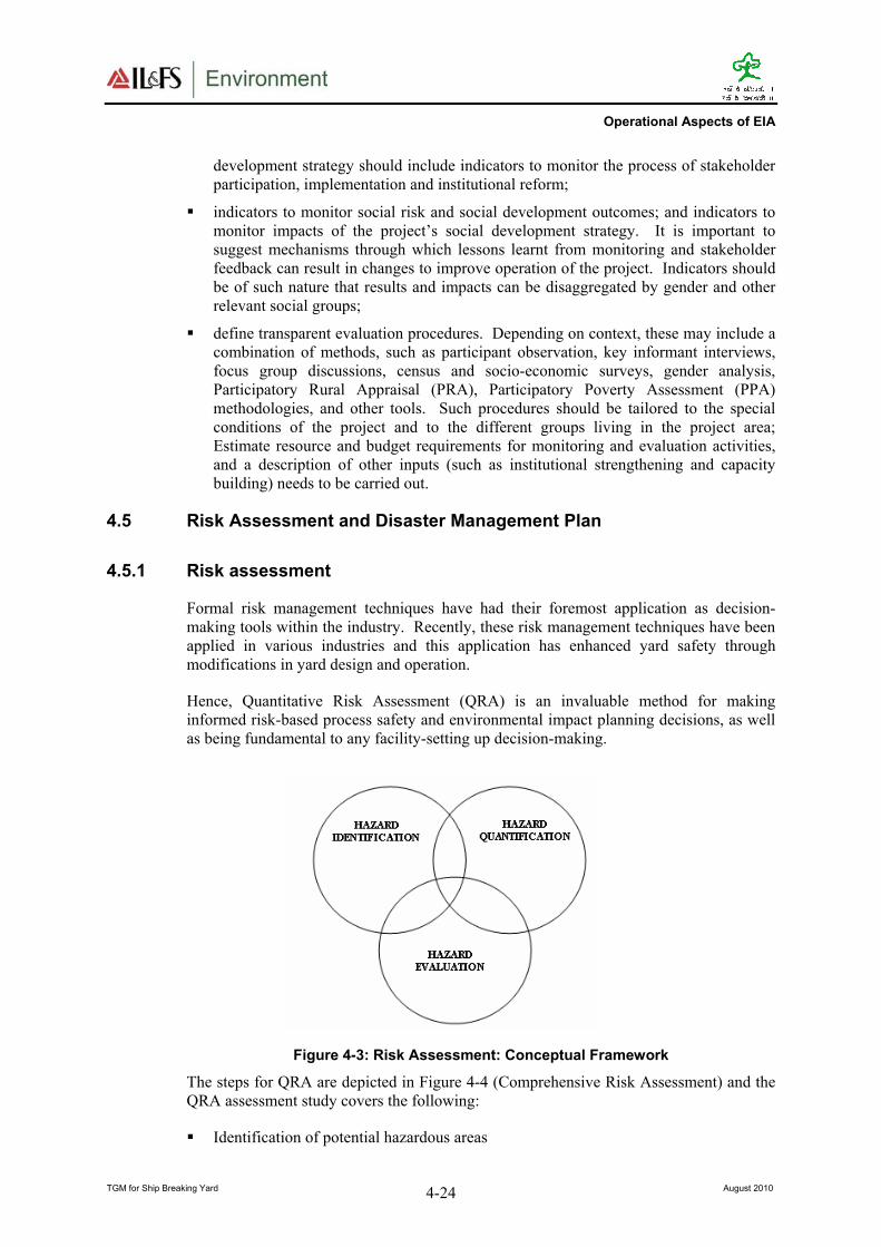
Operational Aspects of EIA
TGM for Ship Breaking Yard August 2010 4-24
development strategy should include indicators to monitor the process of stakeholder
participation, implementation and institutional reform;
indicators to monitor social risk and social development outcomes; and indicators to
monitor impacts of the project’s social development strategy. It is important to
suggest mechanisms through which lessons learnt from monitoring and stakeholder
feedback can result in changes to improve operation of the project. Indicators should
be of such nature that results and impacts can be disaggregated by gender and other
relevant social groups;
define transparent evaluation procedures. Depending on context, these may include a
combination of methods, such as participant observation, key informant interviews,
focus group discussions, census and socio-economic surveys, gender analysis,
Participatory Rural Appraisal (PRA), Participatory Poverty Assessment (PPA)
methodologies, and other tools. Such procedures should be tailored to the special
conditions of the project and to the different groups living in the project area;
Estimate resource and budget requirements for monitoring and evaluation activities,
and a description of other inputs (such as institutional strengthening and capacity
building) needs to be carried out.
4.5 Risk Assessment and Disaster Management Plan
4.5.1 Risk assessment
Formal risk management techniques have had their foremost application as decision-
making tools within the industry. Recently, these risk management techniques have been
applied in various industries and this application has enhanced yard safety through
modifications in yard design and operation.
Hence, Quantitative Risk Assessment (QRA) is an invaluable method for making
informed risk-based process safety and environmental impact planning decisions, as well
as being fundamental to any facility-setting up decision-making.
Figure 4-3: Risk Assessment: Conceptual Framework
The steps for QRA are depicted in Figure 4-4 (Comprehensive Risk Assessment) and the
QRA assessment study covers the following:
Identification of potential hazardous areas

Operational Aspects of EIA
TGM for Ship Breaking Yard August 2010 4-25
Identification of representative failure cases
Visualization of the resulting scenarios in terms of fire
Assessment of the overall damage potential of the identified hazardous events and the
impact zones from the accidental scenarios
Assessment of the overall suitability of the site from hazard minimization and disaster
mitigation points of view
Preparation of recommendations to minimize the worst case accident scenarios and
Preparation of broad DMP, On-site and Off-site Emergency Plan and Occupational
Health and safety plan
Methods of risk predicition should cover all design intentions and operating parameters to
quantify risk in terms of probability of occurrence of hazardous events and magnitude of
its consequence. The following table shows the predicted models for risk assessment.
Table 4-4: Choice of Methods for Impact Prediction: Risk Assessment
Name Application Remarks
EFFECT
WHAZAN
Consequence Analysis for Visualization of
accidental chemical release scenarios & its
consequence
Consequence Analysis for Visualization of
accidental chemical release scenarios & its
consequence
Heat load, press wave &
toxic release exposure
neutral gas dispersion
DEGADIS Consequence Analysis for Visualization of
accidental chemical release scenarios &
its consequence
Dense gas dispersion
HAZOP and Fault
Tree Assessment
For estimating top event probability Failure frequency data is
required
Pathways reliability
and protective system
hazard analysis
For estimating reliability of equipments
and protective systems
Markov models
Vulnerability
Exposure models
Estimation of population exposure Uses probit equation for
population exposure
F-X and F-N curves Individual / Societal risks Graphical
Representation
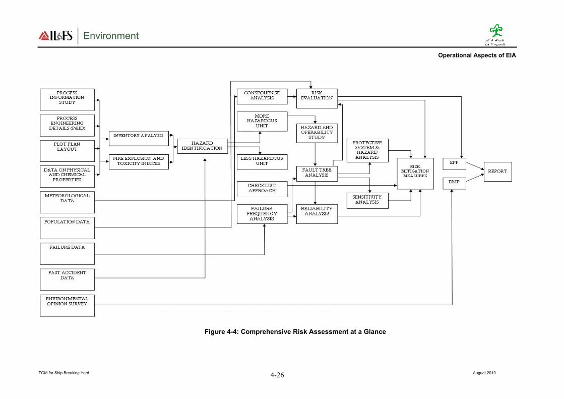
Operational Aspects of EIA
TGM for Ship Breaking Yard Augudt 2010 4-26
Figure 4-4: Comprehensive Risk Assessment at a Glance

Operational Aspects of EIA
TGM for Ship Breaking Yard August 2010 4-27
A. Storage and handling of hazardous materials
During the ship breaking process, hazardous and non-hazardous materials need to be
temporarily accommodated in necessary units placed within yard in line with the safety,
health and environmental standards. The size of these temporary units would depend on
the quantity of waste and type of ship for scrapping. Hazardous materials like asbestos,
PCB, oils, fuels, bilge water, ballast water, etc., with appropriate storage capacities are
placed in the yard following Hazardous Waste Management and Handling Rules.
Damaged ACM pieces cannot be sold and will go to TSDF after proper packaging inside
a centralized land base ventilated enclosure with dress change and bathing facilities.
Radioactive wastes are handled based on Rules for Management of Radioactive Waste
under AERB. Also, gas cylinders must be stored in the yard following the Gas cylinders
Rules under Explosives Act. Later, these materials are disposed off at the centralized
disposal facility with utmost care following safety norms. Every yard should be
facilitated with fire hydrant system to handle fire hazards.
B. Hazard identification
Hazard is the characteristic of any system or process which has the potential for accident.
Identification of hazards during ship breaking process is of primary significance in the
analysis, quantification and cost effective control of accidents involving chemicals and
process.
Hence, all the components of a system need to be thoroughly examined to assess their
potential for initiating or propagating an unplanned event/sequence of events, which can
be termed as an accident.
The typical methods for hazard identification employed are:
Identification of major hazardous units based on Manufacture, Storage and Import of
Hazardous Chemicals Rules, 1989 of Government of India (as amended in 2000); and
Identification of hazardous units and segments of plants and storage units based on
relative ranking technique, viz. Fire Explosion and Toxicity Index (FE&TI).
Hazardous substances may be classified into three main classes namely Flammable
substances, unstable substances and Toxic substances. Flammable substances require
interaction with air for their hazard to be realized. Under certain circumstances the
vapours arising from flammable substances when mixed with air may be explosive,
especially in confined spaces. However, if present in sufficient quantity such clouds may
explode in open air also. Unstable substances are liquids or solids, which may
decompose with such violence so as to give rise to blast waves. Besides, toxic substances
are dangerous and cause substantial damage to life when released into the atmosphere.
The ratings for a large number of chemicals based on flammability, reactivity and toxicity
have been given in NFPA Codes 49 and 345 M.
C. Hazard assessment and evaluation
A preliminary hazard analysis shall be carried out to identify the major hazards associated
with storages in the facility. This is followed by consequence analysis to quantify these
hazards. Finally the vulnerable zones are plotted for which risk reducing measures are
deduced and implemented.
Operational Aspects of EIA
TGM for Ship Breaking Yard August 2010 4-28
Frequent causes of accidents
Fire and explosion: explosives, flammable materials
Being struck by falling objects
Caught in or compressed
Snapping of cables, ropes, chains, slings
Handling heavy objects
Access in progressively dismantled vessels floors, stairs, passageways)
Electricity (electrocution)
Poor illumination
Falls from height inside ship structures or on the ground
Struck by moving objects
Slipping on wet surfaces
Sharp objects
Oxygen deficiency in confined spaces
Lack of PPEs, housekeeping practices, safety signs
Shackles, hooks, chains
Cranes, winches, hoisting and hauling equipment;
Hazardous substances and wastes
Asbestos fibres, dusts
Heavy and toxic metals (lead, mercury, cadmium, copper, zinc, etc.)
Organometallic substances (tributyltin, etc.)
Lack of hazard communication (storage, labelling, material safety data sheets)
Batteries, fire-fighting liquids
PCBs and PVC (combustion products)
Welding fumes
Volatile organic compounds (solvents)
Inhalation in confined and enclosed spaces
Physical hazards
Noise
Extreme temperatures
Vibration
Radiation (UV, radioactive materials)
Physical hazards
Noise
Extreme temperatures
Vibration
Radiation (UV, radioactive materials)
Mechanical hazards
Trucks and transport vehicles
Scaffolding, fixed and portable ladders
Impact by tools, sharp-edged tools
Power-driven hand tools, saws, grinders and abrasive cutting wheels
Failure of machinery and equipment
Poor maintenance of machinery and equipment
Lack of safety guards in machines
Structural failure in the ship
Operational Aspects of EIA
TGM for Ship Breaking Yard August 2010 4-29
Biological hazards
Toxic marine organisms
Risk of communicable diseases transmitted by pests, vermin, rodents, insects and
other animals that may infest the ship
Animal bites
Vectors of infectious diseases (TB, malaria, dengue fever, hepatitis, respiratory
infections, others)
Ergonomic and psychosocial hazards
Repetitive strain injuries, awkward postures, repetitive and monotonous work,
excessive workload
Long working hours, shift work, night work, temporary employment
Mental stress, human relations (aggressive behaviour, alcohol and drug abuse,
violence)
Poverty, low wages, minimum age, lack of education and social environment
General concerns
Lack of safety and health training
Poor work organization
Inadequate housing and sanitation
Inadequate accident prevention and inspection
Inadequate emergency, first-aid and rescue facilities
Lack of medical facilities and social protection
4.5.2 Disaster management plan
A disaster is a catastrophic situation in which suddenly, people are plunged into
helplessness and suffering and, as a result, need protection, clothing, shelter, medical and
social care and other necessities of life.
The DMP is aimed to ensure safety of life, protection of environment, protection of
installation, restoration of production and salvage operations in this same order of
priorities. For effective implementation of the DMP, it should be widely circulated and a
personnel training is to be provided through rehearsals/drills.
To tackle the consequences of a major emergency inside the plant or immediate vicinity
of the plant, a DMP has to be formulated and this planned emergency document is called
the DMP
The objective of the Industrial DMP is to make use of the combined resources of the plant
and the outside services to achieve the following:
Effect the rescue and medical treatment of casualties
Safeguard other people
Minimize damage to property and the environment
Initially contain and ultimately bring the incident under control
Identify any dead
Provide for the needs of relatives
Provide authoritative information to the news media
Secure the safe rehabilitation of affected area

Operational Aspects of EIA
TGM for Ship Breaking Yard August 2010 4-30
Preserve relevant records and equipment for the subsequent inquiry into the cause and
circumstances of the Emergency.
In effect, it is to optimize operational efficiency to rescue rehabilitation and render
medical help and to restore normalcy.
The DMP should include the following:
A. Emergency preparedness plan
Incidents, accidents and emergency preparedness should be accounted during ship
breaking process. This shall be a part of Emergency Management System. Emergency
Preparedness Plan (EPP) should be prepared following the national environmental
emergency plan and OSHA guidelines. According to these guidelines, an environmental
emergency plan would essentially provide the following information:
Assignment of the duties and responsibilities among the authorities, participating
agencies, the response team and coordinators and/or those responsible for the
pollution incident
Relationship with other emergency plans
A reporting system that ensures rapid notification in the event of a pollution incident
The establishment of a focal point for co-ordination and directions connected to the
implementation of the plan
Response operations; should always cover these four phases
− Discovery and alarm
− Evaluation, notification and plan invocation
− Containment and countermeasures
− Cleanup and disposal
Identification of expertise and response resources available for assistance for the
implementation of the plan
Directions on the necessary emergency provisions applicable to the handling,
treatment or disposal of certain pollutants
Link to the local community for assistance, if necessary
Support measures, such as procedures for providing public information, carrying out
surveillance, issuing post incident reports, review and updating of the plan, and
periodic exercising of the plan
B. Emergency response
Dismantling activities at the ship breaking facilities may result in several incidents and
accidents, which may cause several types of damage. For e.g., oil residues and vapors
may represent a fire/explosion hazard during cutting, and falling objects may result in a
variety of cutting injuries. Therefore, a survey of potential incidents and accidents is to
be carried out. Based on this, a plan for response to incidents, injuries and emergencies
should be prepared. Response to emergencies should ensure that:
The exposure of workers should be limited as much as possible during the operation
Contaminated areas should be cleaned and if necessary disinfected
Limited impact on the environment at the extent possible.

Operational Aspects of EIA
TGM for Ship Breaking Yard August 2010 4-31
Written procedures for different types of emergencies should be prepared and the entire
workforce should be trained in emergency response. All relevant emergency response
equipment should also be readily available.
With regard to dangerous spills, associated clean-up and fire-fighting operations should
be carried out by specially allocated and trained personnel.
C. Response team
It is important to setup an Emergency Organization. A senior executive who has control
over the affairs of the plant would be heading the Emergency Organization. He would be
designated as Site Controller. Manager (Safety) would be designated as the Incident
Controller. In the case of stores, utilities, open areas, which are not under the control of
the Production Heads, Senior Executive responsible for maintenance of utilities would be
designated as Incident Controller. All the Incident Controllers would be reporting to the
Site Controller.
Each Incident Controller organizes a team responsible for controlling the incidence with
the personnel under his control. Shift In-charge would be the reporting officer, who
would bring the incidence to the notice of the Incidence Controller and Site Controller.
Emergency Coordinators would be appointed who would undertake the responsibilities
like fire fighting, rescue, rehabilitation, transport and provide essential and support
services. For this purposes, Security In-charge, Personnel Department, Essential services
personnel would be engaged. All these personnel would be designated as Key personnel.
In each shift, electrical supervisor, electrical fitters, pump house in-charge, and other
maintenance staff would be drafted for emergency operations. In the event of power or
communication system failure, some of staff members in the office/facility would be
drafted and their services would be utilized as messengers for quick passing of
communications. All these personnel would be declared as essential personnel.
D. Response to injuries
Based on a survey of possible injuries, a procedure for response to injuries or exposure to
hazardous substances should be established. All staff should have a minimum of training
to such response and the procedure ought to include the following:
Immediate first aid, such as eye splashing, cleansing of wounds and skin, and
bandaging
Immediate reporting to a responsible designated person
If possible, retention of the item and details of its source for identification of possible
hazards
Rapid additional medical care from medical personnel
Medical surveillance
Recording of the incident
Investigation, determination and implementation of remedial action
It is vital that incident reporting should be straightforward so that reporting is actually
carried out.

Operational Aspects of EIA
TGM for Ship Breaking Yard August 2010 4-32
E. Emergency communication
Whoever notices an emergency situation such as fire, growth of fire, leakage, etc., would
inform his immediate superior, Emergency Control Center and local authorities. Also,
there must be a provision for alarm system. The person on duty in the Emergency
Control Center, would appraise the Site Controller. Site Controller verifies the situation
from the Incident Controller of that area or the Shift In-charge and takes a decision about
an impending On-site Emergency. This would be communicated to all the Incident
Controllers, Emergency Coordinators. Simultaneously, the emergency warning system
would be activated on the instructions of the Site Controller. Further, emergency control
centre would alert the ambulances and medical assistance group.
F. Emergency responsibilities
The responsibilities of the key personnel should be defined for the following:
Site controller
Incident controller
Emergency coordinator - rescue, fire fighting
Emergency coordinator-medical, mutual aid, rehabilitation, transport and
communication
Emergency coordinator - essential services
Employers responsibility
G. Emergency facilities
Emergency Control Center – with access to important personnel, telephone, fax, telex
facility, safe contained breathing apparatus, hand tools, emergency shut down
procedures, duties and contact details of key personnel and government agencies,
emergency equipments, etc.
Assembly Point – with minimum facilities for safety and rescue
Emergency Power Supply – connected with diesel generator, flame proof emergency
lamps, etc.
Fire-fighting Facilities – first aid fire fighting equipments, fire alarms, etc.
Location of wind Stock – located at appropriate location to indicate the direction of
wind for emergency escape
Emergency Medical Facilities – Stretchers, gas masks, general first aid, emergency
control room, breathing apparatus, other emergency medical equipment, ambulance
H. Emergency actions
Emergency Warning
Evacuation of Personnel
All Clear Signal
Public information and warning
Coordination with local authorities
Mutual aid
Mock drills
Periodic maintenance and testing of safety equipments
Operational Aspects of EIA
TGM for Ship Breaking Yard August 2010 4-33
4.6 Mitigation Measures
The purpose of mitigation is to identify measures that safeguard the environment and the
community affected by the proposal. Mitigation is both a creative and practical phase of
the EIA process. It seeks best ways and means of avoiding, minimizing and remedying
impacts. Mitigation measures must be translated into action in right way and at the right
time, if they are to be successful. This process is referred to as impact management and
takes place during project implementation. A written plan should be prepared for this
purpose, and should include a schedule of agreed actions. Opportunities for impact
mitigation will occur throughout the project cycle.
4.6.1 Important considerations for mitigation methods
The responsibility of project proponents to ‘internalize’ the full environmental costs of
development proposals is now widely accepted under “Polluter Pay” principle. In
addition, many proponents have found that good design and impact management can
result in significant savings applying the principles of cleaner production to improve their
environmental performance.
The predicted adverse environmental as well as social impacts for which mitigation
measures are required, should be identified and briefly summarized along with cross-
referencing them to the significance, prediction components of the EIA report or
other documentation.
Each mitigation measure should be briefly described w.r.t the impact of significances
to which it relates and the conditions under which it is required (for example,
continuously or in the event of contingencies). These should also be cross-referenced
to the project design and operating procedures which elaborate on the technical
aspects of implementation of various measures.
Cost and responsibilities for mitigation and monitoring should be clearly defined,
including arrangements for coordination between various authorities responsible for
mitigation.
The proponent can use the EMP to develop environmental performance standards and
requirements for the project site as well as supply chain. An EMP can be
implemented through EMS for the operational phase of the project etc.
Before selecting the mitigation plans it is appropriate to study the mitigation alternatives
for cost-effectivity, technical and socio-political feasibility. Such mitigation measures
could include:
avoiding eco/otherwise-sensitive area, e.g., fish spawning areas, dense mangrove
areas or areas known to contain rare or endangered species
adjusting work schedules to minimize disturbance
engineered structures such as berms and noise attenuation barriers
emission criteria need to be met
recycling or reuse of waste materials etc.
Other generic measures
Extend education facility and vocational training to the children of the neighbouring
villages.
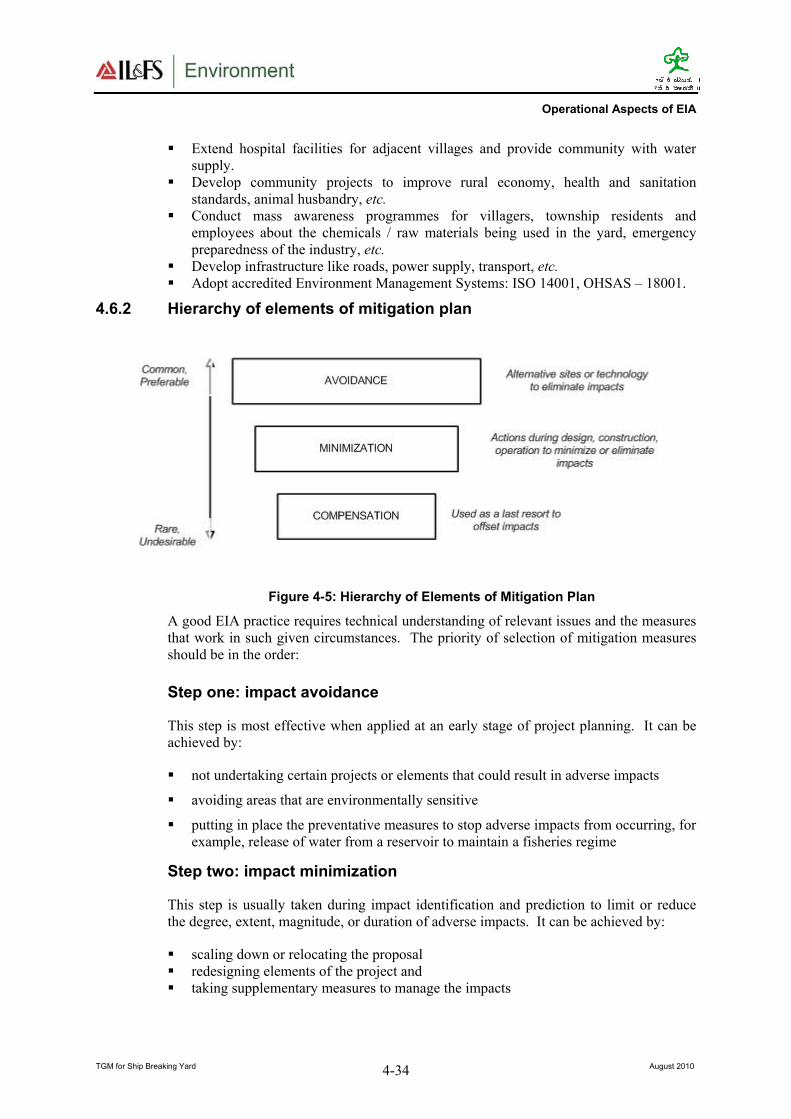
Operational Aspects of EIA
TGM for Ship Breaking Yard August 2010 4-34
Extend hospital facilities for adjacent villages and provide community with water
supply.
Develop community projects to improve rural economy, health and sanitation
standards, animal husbandry, etc.
Conduct mass awareness programmes for villagers, township residents and
employees about the chemicals / raw materials being used in the yard, emergency
preparedness of the industry, etc.
Develop infrastructure like roads, power supply, transport, etc.
Adopt accredited Environment Management Systems: ISO 14001, OHSAS – 18001.
4.6.2 Hierarchy of elements of mitigation plan
Figure 4-5: Hierarchy of Elements of Mitigation Plan
A good EIA practice requires technical understanding of relevant issues and the measures
that work in such given circumstances. The priority of selection of mitigation measures
should be in the order:
Step one: impact avoidance
This step is most effective when applied at an early stage of project planning. It can be
achieved by:
not undertaking certain projects or elements that could result in adverse impacts
avoiding areas that are environmentally sensitive
putting in place the preventative measures to stop adverse impacts from occurring, for
example, release of water from a reservoir to maintain a fisheries regime
Step two: impact minimization
This step is usually taken during impact identification and prediction to limit or reduce
the degree, extent, magnitude, or duration of adverse impacts. It can be achieved by:
scaling down or relocating the proposal
redesigning elements of the project and
taking supplementary measures to manage the impacts

Operational Aspects of EIA
TGM for Ship Breaking Yard August 2010 4-35
Step three: impact compensation
This step is usually applied to remedy unavoidable residual adverse impacts. It can be
achieved by:
rehabilitation of the affected site or environment. For e.g., by habitat enhancement
and restocking fish
restoration of the affected site or environment to its previous state or better,
replacement of the same resource values at another location. For e.g., by wetland
engineering to provide an equivalent area to that lost to drainage, infill, etc.
Important compensation elements
Resettlement Plans: Special considerations apply to mitigation of proposals that displace
or disrupt people. Certain types of projects, such as reservoirs and irrigation schemes and
public works, are known to cause involuntary resettlement. This is a contentious issue
because it involves far more than rehabilitating the people in houses; in addition, income
sources and access to common property resources are likely to be lost. Almost certainly,
a resettlement plan will be required to ensure that no one is worse off than before, which
may not be possible for indigenous people whose culture and lifestyle is tied to a locality.
This plan must include the means for those displaced to reconstruct their economies and
communities and should include an EIA of the receiving areas. Particular attention
should be given to indigenous, minority and vulnerable groups who are at higher risk
from resettlement.
In-kind compensation
When significant or net residual loss or damage to the environment is likely, in-kind
compensation is appropriate. As noted earlier, environmental rehabilitation, restoration or
replacement have become standard practices for many proponents. Now, increasing
emphasis is given to a broader range of compensation measures to offset impacts and
assure the sustainability of development proposals. These include impact compensation
‘trading’, such as offsetting CO2 emissions by planting forests to sequester carbon.
4.6.3 Typical mitigation measures
Choice of location for the developmental activity plays an important role in preventing
the adverse impacts on the surrounding environment. Detailed guidelines on siting of
industries are provided in Section 4.2. However, if the developmental activity still
produces any adverse impacts, mitigation measures should be taken.
Previous subsections of the Section 4.6 could be precisely summarized into following:
Impacts from a developmental project could have many dimensions. As most of the
direct impacts are caused by the releases from developmental projects, often impact
control at source is the best opportunity to either eliminate or mitigate the impacts, in
case these are cost-effective. In other words, the best way to mitigate the impacts is
to prevent them from occurring. Choice of raw materials/technologies/processes
which produce least impact would be one of the options to achieve it.
After exploring cost-effective feasible alternatives to control impacts at source,
various interventions to minimize the adverse impacts may be considered. These

Operational Aspects of EIA
TGM for Ship Breaking Yard August 2010 4-36
interventions, primarily aim at reducing the residual impacts on the valued
environmental components of the receiving environment to the acceptable
concentrations.
The degree of control at source and external interventions differs from situation-to -
situation and are largely governed by techno-economic feasibility. While the
regulatory bodies stress for further source control (due to high reliability), the project
proponents bargain for other interventions which may be relatively cost-effective than
further control at source (in any case project authority is required to meet the
industry-specific standards by adopting the best practicable technologies. However,
if the location demands further control at source, then the proponents are required to
adopt further advanced control technologies i.e. towards best available control
technologies). After having discussions with the project proponent, EAC/SEAC
reaches to an agreed level of source control+other interventions (together called as
mitigation measures in the given context) that achieve the targeted protection levels
for the valued environmental components in the receiving environment. These levels
will become the principle clearance conditions.
Chapter 3 of this TGM offers elaborate information on cleaner technologies, waste
minimization opportunities, and control technologies for various kinds of polluting
parameters that emanate from this developmental activity (put sector name). This
information may be used to draw appropriate source control measures.
The choice of interventions for mitigation of impacts may also be numerous and depend
on various factors. Mitigation measures based on location-specific suitability and some
other factors are discussed in sub-sections 4.6.1 and 4.6.2. A few typical measures which
may also be explored for mitigation of impacts are listed in Table 4-5.
Table 4-5: Typical Mitigation Measures
Impacts Mitigation steps
Environmental Impacts
Soil Pollution Use concrete payment in the recycling unit before the start of activities
Adequate containment methods in collecting the liquid waste
Cutting and breaking operations in a systematic way
Dust pollution Wetting of roadways to reduce traffic dust and reentrained particles
Installation of windscreens to breakup the wind flow
Noise pollution Heavy duty muffler systems on heavy equipment
Water pollution and issues Channeling and retention of water to reduce erosion and situation
Collection and treatment of sewage and organic waste
Appropriate disposal of solids
Construct liners of ponds and solids waste disposal
Dilute water at point of discharge
Chemical discharges and spills Develop spill prevention plans
Develop traps and containment system and chemically treat discharges on
site
Biological Installation of systems to discourage nesting or perching of birds in
dangerous environments
Increased employee awareness to sensitive areas
Disruption of traffic Develop traffic plan that minimizes road use by workers
Upgrade roads and intersections
Health Impacts
Worker exposure to dust Provide dust collector equipment
Maintain dust levels less than 10 mg/m3
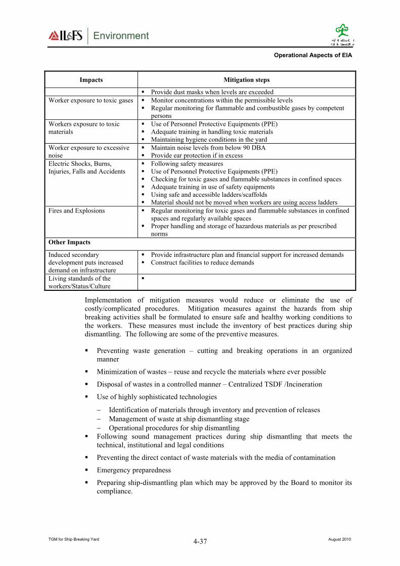
Operational Aspects of EIA
TGM for Ship Breaking Yard August 2010 4-37
Impacts Mitigation steps
Provide dust masks when levels are exceeded
Worker exposure to toxic gases Monitor concentrations within the permissible levels
Regular monitoring for flammable and combustible gases by competent
persons
Workers exposure to toxic
materials
Use of Personnel Protective Equipments (PPE)
Adequate training in handling toxic materials
Maintaining hygiene conditions in the yard
Worker exposure to excessive
noise
Maintain noise levels from below 90 DBA
Provide ear protection if in excess
Electric Shocks, Burns,
Injuries, Falls and Accidents
Following safety measures
Use of Personnel Protective Equipments (PPE)
Checking for toxic gases and flammable substances in confined spaces
Adequate training in use of safety equipments
Using safe and accessible ladders/scaffolds
Material should not be moved when workers are using access ladders
Fires and Explosions Regular monitoring for toxic gases and flammable substances in confined
spaces and regularly available spaces
Proper handling and storage of hazardous materials as per prescribed
norms
Other Impacts
Induced secondary
development puts increased
demand on infrastructure
Provide infrastructure plan and financial support for increased demands
Construct facilities to reduce demands
Living standards of the
workers/Status/Culture
Implementation of mitigation measures would reduce or eliminate the use of
costly/complicated procedures. Mitigation measures against the hazards from ship
breaking activities shall be formulated to ensure safe and healthy working conditions to
the workers. These measures must include the inventory of best practices during ship
dismantling. The following are some of the preventive measures.
Preventing waste generation – cutting and breaking operations in an organized
manner
Minimization of wastes – reuse and recycle the materials where ever possible
Disposal of wastes in a controlled manner – Centralized TSDF /Incineration
Use of highly sophisticated technologies
− Identification of materials through inventory and prevention of releases
− Management of waste at ship dismantling stage
− Operational procedures for ship dismantling
Following sound management practices during ship dismantling that meets the
technical, institutional and legal conditions
Preventing the direct contact of waste materials with the media of contamination
Emergency preparedness
Preparing ship-dismantling plan which may be approved by the Board to monitor its
compliance.
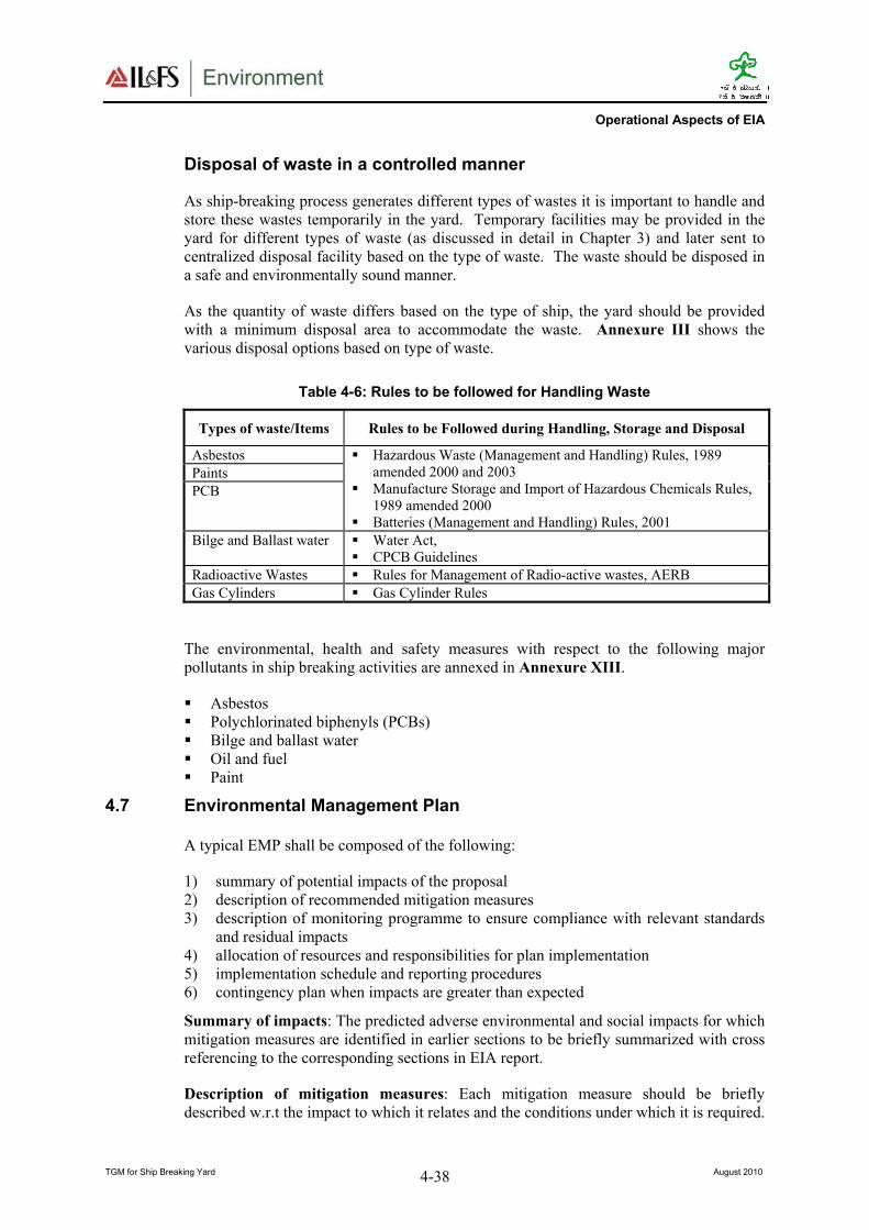
Operational Aspects of EIA
TGM for Ship Breaking Yard August 2010 4-38
Disposal of waste in a controlled manner
As ship-breaking process generates different types of wastes it is important to handle and
store these wastes temporarily in the yard. Temporary facilities may be provided in the
yard for different types of waste (as discussed in detail in Chapter 3) and later sent to
centralized disposal facility based on the type of waste. The waste should be disposed in
a safe and environmentally sound manner.
As the quantity of waste differs based on the type of ship, the yard should be provided
with a minimum disposal area to accommodate the waste. Annexure III shows the
various disposal options based on type of waste.
Table 4-6: Rules to be followed for Handling Waste
Types of waste/Items Rules to be Followed during Handling, Storage and Disposal
Asbestos
Paints
PCB
Hazardous Waste (Management and Handling) Rules, 1989
amended 2000 and 2003
Manufacture Storage and Import of Hazardous Chemicals Rules,
1989 amended 2000
Batteries (Management and Handling) Rules, 2001
Bilge and Ballast water Water Act,
CPCB Guidelines
Radioactive Wastes Rules for Management of Radio-active wastes, AERB
Gas Cylinders Gas Cylinder Rules
The environmental, health and safety measures with respect to the following major
pollutants in ship breaking activities are annexed in Annexure XIII.
Asbestos
Polychlorinated biphenyls (PCBs)
Bilge and ballast water
Oil and fuel
Paint
4.7 Environmental Management Plan
A typical EMP shall be composed of the following:
1) summary of potential impacts of the proposal
2) description of recommended mitigation measures
3) description of monitoring programme to ensure compliance with relevant standards
and residual impacts
4) allocation of resources and responsibilities for plan implementation
5) implementation schedule and reporting procedures
6) contingency plan when impacts are greater than expected
Summary of impacts: The predicted adverse environmental and social impacts for which
mitigation measures are identified in earlier sections to be briefly summarized with cross
referencing to the corresponding sections in EIA report.
Description of mitigation measures: Each mitigation measure should be briefly
described w.r.t the impact to which it relates and the conditions under which it is required.

Operational Aspects of EIA
TGM for Ship Breaking Yard August 2010 4-39
These should be accompanied by/referenced to, project design and operating procedures
which elaborate on the technical aspects of implementing various measures.
Description of monitoring programme to ensure compliance with relevant standards
and residual impacts: Environmental monitoring refers to compliance monitoring and
residual impact monitoring. Compliance monitoring refers to meeting the industry-
specific statutory compliance requirements (Ref. Applicable National regulations as
detailed in Chapter 3).
Residual impact monitoring refers to monitoring of identified sensitive locations with
adequate number of samples and frequency. The monitoring programme should clearly
indicate the linkages between impacts identified in the EIA report, measurement
indicators, detection limits (where appropriate), and definition of thresholds that will
signal the need for corrective actions.
Allocation of resources and responsibilities for plan implementation: These should be
specified for both the initial investment and recurring expenses for implementing all
measures contained in the EMP, integrated into the total project costs, and factored into
loan negotiation.
The EMP should contain commitments that are binding on the proponent in different
phases of project implementation i.e., pre-construction or site clearance, construction,
operation, decommissioning.
Responsibilities for mitigation and monitoring should be clearly defined, including
arrangements for coordination between various actors responsible for mitigation. Details
should be provided w.r.t deployment of staff (detailed organogram), monitoring network
design, parameters to be monitored, analysis methods, associated equipments, etc.
Contingency Plan when the impacts are greater than expected: There shall be a
contingency plan for attending to the situations where the monitoring results shows
residual impacts are higher than expected. It is an imperative requirement for all the
project authorities to plan additional programmes to deal with the situation, after duly
intimating the concerned local regulatory bodies.
4.8 Reporting
Structure of the EIA report (Appendix III of the EIA Notification), applicable for ship
breaking yards is given in the following Table 4-7. Each task prescribed in ToR shall be
incorporated appropriately in the contents in addition to the contents described in the table
below.
Table 4-7: Structure of EIA Report
S.NO EIA STRUCTURE CONTENTS
1. Introduction Purpose of the report
Identification of project & project proponent
Brief description of nature, size, location of the project and
its importance to the country, region
Scope of the study – details of regulatory scoping carried
out (As per ToR)
2. Project Description Condensed description of those aspects of the project (based on
project feasibility study), likely to cause environmental effects.
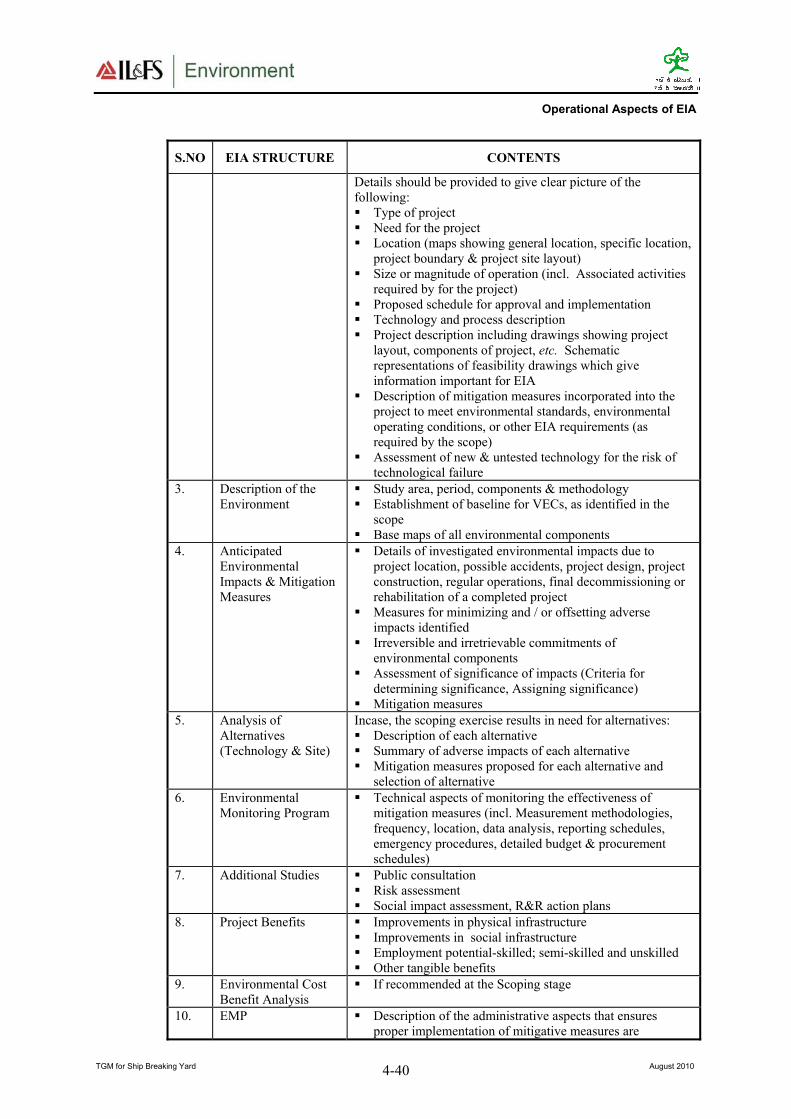
Operational Aspects of EIA
TGM for Ship Breaking Yard August 2010 4-40
S.NO EIA STRUCTURE CONTENTS
Details should be provided to give clear picture of the
following:
Type of project
Need for the project
Location (maps showing general location, specific location,
project boundary & project site layout)
Size or magnitude of operation (incl. Associated activities
required by for the project)
Proposed schedule for approval and implementation
Technology and process description
Project description including drawings showing project
layout, components of project, etc. Schematic
representations of feasibility drawings which give
information important for EIA
Description of mitigation measures incorporated into the
project to meet environmental standards, environmental
operating conditions, or other EIA requirements (as
required by the scope)
Assessment of new & untested technology for the risk of
technological failure
3. Description of the
Environment
Study area, period, components & methodology
Establishment of baseline for VECs, as identified in the
scope
Base maps of all environmental components
4. Anticipated
Environmental
Impacts & Mitigation
Measures
Details of investigated environmental impacts due to
project location, possible accidents, project design, project
construction, regular operations, final decommissioning or
rehabilitation of a completed project
Measures for minimizing and / or offsetting adverse
impacts identified
Irreversible and irretrievable commitments of
environmental components
Assessment of significance of impacts (Criteria for
determining significance, Assigning significance)
Mitigation measures
5. Analysis of
Alternatives
(Technology & Site)
Incase, the scoping exercise results in need for alternatives:
Description of each alternative
Summary of adverse impacts of each alternative
Mitigation measures proposed for each alternative and
selection of alternative
6. Environmental
Monitoring Program
Technical aspects of monitoring the effectiveness of
mitigation measures (incl. Measurement methodologies,
frequency, location, data analysis, reporting schedules,
emergency procedures, detailed budget & procurement
schedules)
7. Additional Studies Public consultation
Risk assessment
Social impact assessment, R&R action plans
8. Project Benefits Improvements in physical infrastructure
Improvements in social infrastructure
Employment potential-skilled; semi-skilled and unskilled
Other tangible benefits
9. Environmental Cost
Benefit Analysis
If recommended at the Scoping stage
10. EMP Description of the administrative aspects that ensures
proper implementation of mitigative measures are

Operational Aspects of EIA
TGM for Ship Breaking Yard August 2010 4-41
S.NO EIA STRUCTURE CONTENTS
implemented and their effectiveness monitored, after
approval of the EIA
11. Summary &
Conclusion (This will
constitute the
summary of the EIA
Report)
Overall justification for implementation of the project
Explanation of how, adverse effects have been mitigated
Implementation of clean development mechanism to
conserve natural resources
12. Disclosure of
Consultants engaged
Names of the Consultants engaged with their brief resume
and nature of Consultancy rendered
4.9 Public Consultation
Public consultation refers to the process by which the concerns of local affected people
and others who have plausible stake in the environmental impacts of the project or
activity are ascertained.
Public consultation is not a decision taking process, but is a process to collect views
of the people having plausible stake. If the SPCB/Public agency conducting public
hearing is not convinced with the plausible stake, then such expressed views need not
be considered.
All Category A projects require public hearing except the following:
− All building/ construction projects/ area development projects/townships
− All projects concerning national defense and security or involving other strategic
considerations as determined by the Central Government
Public consultation involves two components, one is public hearing, and other one is
inviting written responses/objections through Internet/by post, etc., by placing the
summary of EIA report on the website.
Public hearing shall be carried out at the site or in its close proximity, district-wise,
for ascertaining concerns of local affected people.
Project proponent shall make a request through a simple letter to the Member-
Secretary of the SPCB or UTPCC to arrange public hearing.
Project proponent shall enclose with the letter of request, at least 10 hard copies and
10 soft copies of the draft EIA report including the summary EIA report in English
and in the official language of the State/local language prepared as per the approved
scope of work, to the concerned Authority.
Simultaneously, project proponent shall arrange to send, one hard copy and one soft
copy, of the above draft EIA report along with the summary EIA report to the
following Authorities within whose jurisdiction the project will be located:
− District magistrate(s) /District Collector/Deputy Commissioner (s)
− Zilla parishad and municipal corporation or panchayats union
− District industries office
− Urban local bodies (ULBs)/PRIs concerned/development authorities
− Concerned regional office of the MoEF/SPCB
Above mentioned Authorities except regional office of MoEF shall arrange to widely
publicize the draft EIA report within their respective jurisdictions requesting the
interested persons to send their comments to the concerned regulatory authorities.

Operational Aspects of EIA
TGM for Ship Breaking Yard August 2010 4-42
They shall also make draft EIA report for inspection electronically or otherwise to the
public during normal office hours till the public hearing is over.
Concerned regulatory Authority (MoEF) shall display the summary of EIA report on
its website and also make full draft EIA report available for reference at a notified
place during normal office hours at their head office.
SPCB or UTPCC concerned shall also make similar arrangements for giving publicity
about the project within the State/UT and make available the summary of draft EIA
report for inspection in select offices, public libraries or any other suitable location,
etc. They shall also additionally make available a copy of the draft EIA report to the
five authorities/offices as mentioned.
The Member-Secretary of the concerned SPCB or UTPCC shall finalize the date,
time and exact venue for the conduct of public hearing within seven days of the date
of the receipt of the draft EIA report from the project proponent and advertise the
same in one major National Daily and one Regional vernacular Daily/official State
language.
A minimum notice period of 30 (thirty) days shall be provided to the public for
furnishing their responses.
No postponement of the date, time, venue of the public hearing shall be undertaken,
unless some untoward emergency situation occurs. Only in case of emergencies and
up on the recommendation of the concerned District Magistrate/District
Collector/Deputy Commissioner the postponement shall be notified to the public
through the same National and Regional vernacular dailies and also prominently
displayed at all the identified offices by the concerned SPCB or UTPCC
In the above exceptional circumstances fresh date, time and venue for the public
consultation shall be decided by the Member –Secretary of the concerned SPCB or
UTPCC only in consultation with the District Magistrate/District Collector/Deputy
Commissioner and notified afresh as per the procedure.
The District Magistrate/District Collector/Deputy Commissioner or his or her
representative not below the rank of an Additional District Magistrate assisted by a
representative of SPCB or UTPCC, shall supervise and preside over the entire public
hearing process.
The SPCB or UTPCC shall arrange to video film the entire proceedings. A copy of
the videotape or a CD shall be enclosed with the public hearing proceedings while
forwarding it to the Regulatory Authority concerned.
The attendance of all those who are present at the venue shall be noted and annexed
with the final proceedings
There shall be no quorum required for attendance for starting the proceedings
Persons present at the venue shall be granted the opportunity to seek information or
clarifications on the project from the proponent. The summary of the public hearing
proceedings accurately reflecting all the views and concerns expressed shall be
recorded by the representative of the SPCB or UTPCC and read over to the audience
at the end of the proceedings explaining the contents in the local/vernacular language
and the agreed minutes shall be signed by the District Magistrate/District
Collector/Deputy Commissioner or his or her representative on the same day and
forwarded to the SPCB/UTPCC concerned.
Operational Aspects of EIA
TGM for Ship Breaking Yard August 2010 4-43
A statement of the issues raised by the public and the comments of the proponent
shall also be prepared in the local language or the official State language, as the case
may be and in English and annexed to the proceedings.
The proceedings of the public hearing shall be conspicuously displayed at the office
of the Panchayats within whose jurisdiction the project is located, office of the
concerned Zilla Parishad, District Magistrate/District Collector/Deputy
Commissioner and the SPCB or UTPCC. The SPCB or UTPCC shall also display the
proceedings on its website for general information. Comments, if any, on the
proceedings, may be sent directly to the concerned regulatory authorities and the
Applicant concerned.
The public hearing shall be completed within a period of 45 (forty five) days from
date of receipt of the request letter from the Applicant. Therefore the SPCB or
UTPCC concerned shall send public hearing proceedings to the concerned regulatory
Authority within eight (8) days of the completion of public hearing. Simultaneously,
a copy will also be provided to the project proponent. The proponent may also
directly forward a copy of the approved public hearing proceedings to the regulatory
Authority concerned along with the final EIA report or supplementary report to the
draft EIA report prepared after the public hearing and public consultations
incorporating the concerns expressed in the public hearing along with action plan and
financial allocation, item-wise, to address those concerns.
Up on receipt of the same, the Authority will place executive summary of the report
on the website to invite responses from other concerned persons having a plausible
stake in the environmental aspects of the project or activity.
If SPCB/UTPCC is unable to conduct public hearing in the prescribed time, the
Central Government at the request of the SEIAA can engage a public agency or
authority for conducting the public hearing process within a further period of 45 days.
The respective governments shall pay the appropriate fee to the public agency for
conducting public hearing.
A public agency means a non-profit making institution/ body such as
technical/academic institutions, government bodies not subordinate to the concerned
Authority.
If SPCB/Public Agency authorized for conducting public hearing informs the
Authority, stating that it is not possible to conduct the public hearing in a manner,
which will enable the views of the concerned local persons to be freely expressed,
then Authority may consider such report to take a decision that in such particular
case, public consultation may not have the component of public hearing.
Often restricting the public hearing to the specific district may not serve the entire
purpose, therefore, NGOs who are local and registered under the Societies Act in the
adjacent districts may also be allowed to participate in public hearing, if they so
desire.
Confidential information including non-disclosable or legally privileged information
involving intellectual property right, source specified in the application shall not be
placed on the website.
The Authority shall make available, on a written request from any concerned person
the draft EIA report for inspection at a notified place during normal office hours till
the date of the public hearing.
Operational Aspects of EIA
TGM for Ship Breaking Yard August 2010 4-44
While mandatory requirements will have to be adhered to, utmost attention shall be
given to the issues raised in the public hearing for determining the modifications
needed in the project proposal and the EMP to address such issues.
Final EIA report after making needed amendments, as aforesaid, shall be submitted
by the applicant to the concerned Authority for prior environmental clearance.
Alternatively, a supplementary report to draft EIA and EMP addressing all concerns
expressed during the public consultation may be submitted.
4.10 Appraisal
Appraisal means the detailed scrutiny by the EAC of the application and the other
documents like the final EIA report, outcome of the public consultation including public
hearing proceedings submitted by the applicant for grant of environmental clearance.
The appraisal shall be made by EAC concerned to the Central Government and the
SEIAA respectively.
Project proponent either personally or through consultant can make a presentation to
the EAC for the purpose of appraising the features of the project proposal and also to
clarify the issues raised by the members of the EAC.
On completion of these proceedings EAC shall make categorical recommendations to
the respective Authority, either for grant of prior environmental clearance on
stipulated terms & conditions, if any, or rejection of the application with reasons.
In case EAC needs to visit the site or obtain further information before being able to
make categorical recommendations, EAC may inform the project proponent
accordingly. In such an event, it should be ensured that the process of environmental
clearance is not unduly delayed to go beyond the prescribed timeframe.
Up on the scrutiny of the final report, if EAC opines that ToR finalized at the scoping
stage has not been covered by the proponent, then the project proponent may be asked
to provide such information. If such information is declined by the project proponent
or is unlikely to be provided early enough so as to complete the environmental
appraisal within prescribed time of 60 days, the EAC may recommend for rejection of
the proposal with the same reason.
Appraisal shall be strictly in terms of ToR finalized at the scoping stage and the
concerns expressed during public consultation.
This process of appraisal shall be completed within 60 days from receipt of the
updated EIA and EMP reports, after completing public consultation.
The EIA report will be typically examined for following:
− Project site description supported by topographic maps & photographs – detailed
description of topography, land use and activities at the proposed project site and
its surroundings (buffer zone) supported by photographic evidence.
− Clarity in description of drainage pattern, location of eco-sensitive areas,
vegetation characteristics, wildlife status - highlighting significant environmental
attributes such as feeding, breeding and nesting grounds of wildlife species,
migratory corridor, wetland, erosion and neighboring issues.
− Description of the project site – how well the interfaces between the project
related activities and the environment have been identified for the entire project
Operational Aspects of EIA
TGM for Ship Breaking Yard August 2010 4-45
cycle i.e., construction, operation and decommissioning at the end of the project
life.
− How complete and authentic are the baseline data pertaining to flora and fauna
and socio-economic aspects?
− Citing of proper references, with regard to the source(s) of baseline data as well
as the name of the investigators/ investigating agency responsible for collecting
the primary data.
− How consistent are the various values of environmental parameters with respect
to each other?
− Is a reasonable assessment of the environmental and social impact made for the
identified environmental issues including project affected people?
− To what extent the proposed environmental plan will mitigate the environmental
impact and at what estimated cost, shown separately for construction, operation
and closure stages and also separately in terms of capital and recurring expenses
along with details of agencies that will be responsible for the implementation of
environmental plan/ conservation plan.
− How well are the concerns expressed/highlighted during the public hearing have
been addressed and incorporated in the EMP giving item wise financial
provisions and commitments (in quantified terms)?
− How far the proposed environmental monitoring plan will effectively evaluate the
performance of EMP? Are details for environmental monitoring plan provided in
the same manner as the EMP?
− Identification of hazard and quantification of risk assessment and whether
appropriate mitigation plan has been included in the EMP?
− Does the proposal include a well formulated, time-bound green belt development
plan for mitigating environmental problems such as fugitive emissions of dust,
gaseous pollutants, noise, odour, etc.?
− Does EIA make a serious attempt to guide the project proponent for minimizing
the requirement of natural resources including land, water energy and other non
renewable resources?
− How well has the EIA statement has been organized and presented so that the
issues, their impact and environmental management strategies emerge clearly
from it and how well organized was the power point presentation made before the
expert committee?
− Is the information presented in EIA adequately and appropriately supported by
maps, imageries and photographs highlighting site features and environmental
attributes?
Operational Aspects of EIA
TGM for Ship Breaking Yard August 2010 4-46
4.11 Decision-making
The Chairperson reads the sense of the Committee and finalizes the draft minutes of the
meeting, which are circulated by the Secretary to all the expert members invited to the
meeting. Based on the response from the members, the minutes are finalized and signed
by the Chairperson. This process for finalization of the minutes should be so organized
that the time prescribed for various stages is not exceeded.
Approval / rejection / reconsideration
The Authority shall consider the recommendations of concerned appraisal Committee and
convey its decision within 45 days of the receipt of recommendations.
If the Authority disagrees with the recommendations of the Appraisal Committee,
then reasons shall be communicated to concerned Appraisal Committee and applicant
within 45 days from the receipt of the recommendations. The Appraisal Committee
concerned shall consider the observations of the Authority and furnish its views on
the observations within further period of 60 days. The Authority shall take a decision
within the next 30 days based on the views of appraisal Committee.
If the decision of the Authority is not conveyed within the time, then the proponent
may proceed as if the environmental clearance sought has been granted or denied by
the regulatory Authority in terms of the final recommendation of the concerned
appraisal Committee. For this purpose, the decision of the Appraisal Committee will
be a public document, once the period specified above for taking the decision by the
Authority is over.
Deliberate concealment and/or submission of false or misleading information or data
which is material to screening or scoping or appraisal or decision on the application
shall make the application liable for rejection, and cancellation of prior environmental
clearance granted on that basis. Rejection of an application or cancellation of a prior
environmental clearance already granted, on such ground, shall be decided by the
regulatory authority, after giving a personal hearing to the applicant, and following
the principles of natural justice.
If approved
The MoEF will issue the environmental clearance for the project.
The project proponent should make sure that the award of environmental clearance is
properly publicized in at least two local newspapers of the district or state where the
proposed project is located. For instance, the executive summary of the
environmental clearance may be published in the newspaper along with the
information about the location (website/office where it is displayed for public) where
the detailed environmental clearance is made available. The MoEF shall also place
the environmental clearance in the public domain on Government Portal. Further
copies of the environmental clearance shall be endorsed to the Heads of local bodies,
Panchayats and Municipal bodies in addition to the relevant offices of the
Government.
The environmental clearance will be valid from the start date to actual
commencement of the production of the developmental activity.
Usual validity period will be 5 years from the date of issuing environmental
clearance, unless specified by EAC.
Operational Aspects of EIA
TGM for Ship Breaking Yard August 2010 4-47
A prior environmental clearance issued to a project proponent can be transferred to
another legal person entitled to undertake the project, upon application by the
transferor to the concerned Authority or submission of no-objection of the transferor
by the transferee to the concerned Authority for the concurrence. In this case, EAC
concurrence is not required, but approval from the concerned authority is required to
avail the same project configurations, validity period transferred to the new legally
entitled person to undertake the project.
4.12 Post-clearance Monitoring Protocol
The MoEF will monitor and take appropriate action under the EP Act, 1986.
In respect of Category A projects, it shall be mandatory for the project proponent to
make public the environmental clearance granted for their project along with the
environmental conditions and safeguards at their cost by advertising it at least in two
local newspapers of the district or State where the project is located and in addition,
this shall also be displayed in the project proponent’s website permanently.
The MoEF shall also place the environmental clearance in the public domain on
Government Portal.
Copies of the environmental clearance shall be submitted by the project proponents to
the Heads of the local bodies, Panchayats and Municipal bodies in addition to the
relevant offices of the Government who in turn have to display the same for 30 days
from the date of receipt.
The project proponent must submit half-yearly compliance reports in respect of the
stipulated prior environmental clearance terms and conditions in hard and soft copies to
the regulatory Authority concerned, on 1st June and 1st December of each calendar year.
All such compliance reports submitted by the project management shall be public
documents. Copies of the same shall be given to any person on application to the
concerned regulatory Authority. Such latest compliance report shall also be displayed on
the website of the concerned regulatory Authority.
The SPCB shall incorporate EIA clearance conditions into consent conditions in respect
of Category A and Category B projects and in parallel monitor and enforce the same.
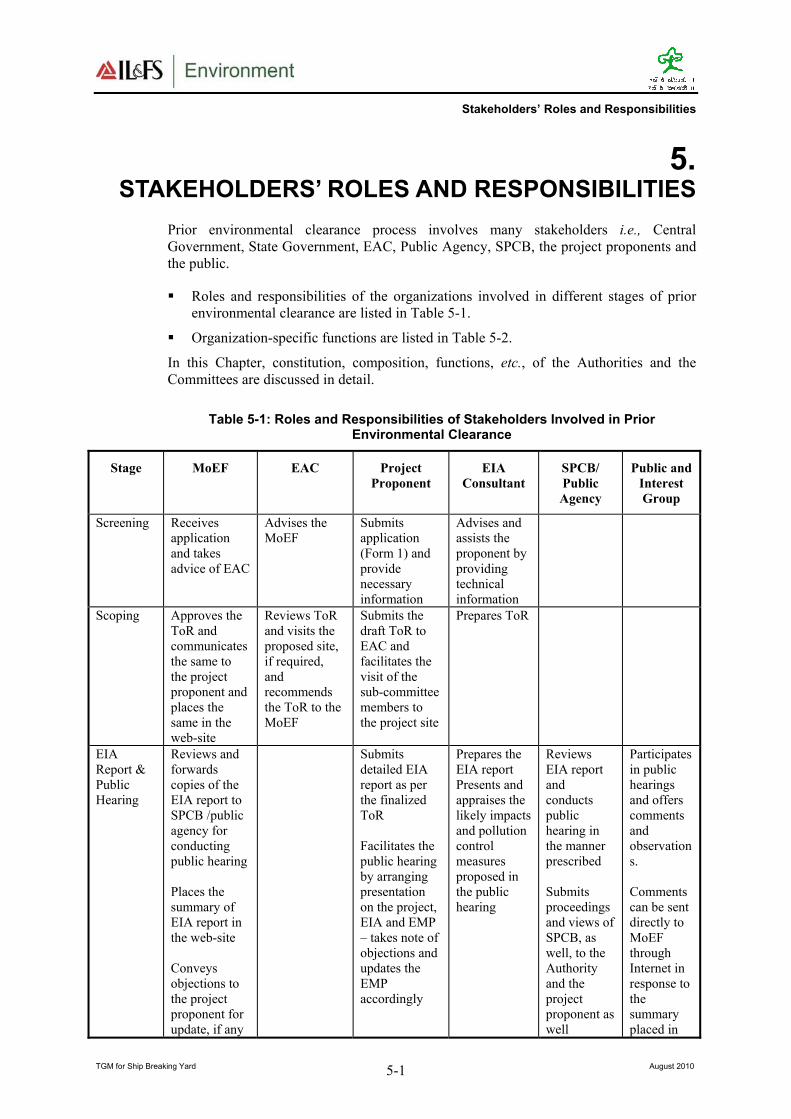
Stakeholders’ Roles and Responsibilities
TGM for Ship Breaking Yard August 2010 5-1
5. STAKEHOLDERS’ ROLES AND RESPONSIBILITIES
Prior environmental clearance process involves many stakeholders i.e., Central
Government, State Government, EAC, Public Agency, SPCB, the project proponents and
the public.
Roles and responsibilities of the organizations involved in different stages of prior
environmental clearance are listed in Table 5-1.
Organization-specific functions are listed in Table 5-2.
In this Chapter, constitution, composition, functions, etc., of the Authorities and the
Committees are discussed in detail.
Table 5-1: Roles and Responsibilities of Stakeholders Involved in Prior Environmental Clearance
Stage MoEF EAC Project
Proponent
EIA
Consultant
SPCB/
Public
Agency
Public and
Interest
Group
Screening Receives
application
and takes
advice of EAC
Advises the
MoEF
Submits
application
(Form 1) and
provide
necessary
information
Advises and
assists the
proponent by
providing
technical
information
Scoping Approves the
ToR and
communicates
the same to
the project
proponent and
places the
same in the
web-site
Reviews ToR
and visits the
proposed site,
if required,
and
recommends
the ToR to the
MoEF
Submits the
draft ToR to
EAC and
facilitates the
visit of the
sub-committee
members to
the project site
Prepares ToR
EIA
Report &
Public
Hearing
Reviews and
forwards
copies of the
EIA report to
SPCB /public
agency for
conducting
public hearing
Places the
summary of
EIA report in
the web-site
Conveys
objections to
the project
proponent for
update, if any
Submits
detailed EIA
report as per
the finalized
ToR
Facilitates the
public hearing
by arranging
presentation
on the project,
EIA and EMP
– takes note of
objections and
updates the
EMP
accordingly
Prepares the
EIA report
Presents and
appraises the
likely impacts
and pollution
control
measures
proposed in
the public
hearing
Reviews
EIA report
and
conducts
public
hearing in
the manner
prescribed
Submits
proceedings
and views of
SPCB, as
well, to the
Authority
and the
project
proponent as
well
Participates
in public
hearings
and offers
comments
and
observation
s.
Comments
can be sent
directly to
MoEF
through
Internet in
response to
the
summary
placed in

Stakeholders’ Roles and Responsibilities
TGM for Ship Breaking Yard August 2010 5-2
Stage MoEF EAC Project
Proponent
EIA
Consultant
SPCB/
Public
Agency
Public and
Interest
Group
the website
Appraisal
and
Clearance
Receives
updated EIA
Takes advice
of EAC, and
takes decision
(Clearance
with required
conditions or
re-
examination/r
ejection
Critically
examines the
reports,
presentation of
the proponent
and appraises
MoEF
(recommendati
ons are
forwarded to
MoEF)
Submits up-
dated EIA,
EMP reports to
MoEF.
Presents the
overall EIA
and EMP
including
public
concerns to
EAC
Provides
technical
advise to the
project
proponent
and if
necessary
presents the
proposed
measures for
mitigation of
likely impacts
(terms and
conditions of
clearance)
Post
Clearance
Monitoring
Implements
environmental
protection
measures
prescribed and
submits
periodic
monitoring
results
Conducts
periodic
monitoring
Incorporates
the
clearance
conditions
into
appropriate
consent
conditions
and ensures
implementat
ion
Table 5-2: Organization-specific Functions
Organization Functions
Central
Government
Constitutes the EAC
Receives application from the project proponent
Communicates the ToR finalized by the EAC to the project proponent
Receives EIA report from the project proponent and soft copy of summary of the report for
placing in the website
Summary of EIA report will be placed in website. Forwards the received responses to the
project proponent
Engages other public agency for conducting public hearing in case where the SPCB does
not respond within time
Receives updated EIA report from project proponent incorporating the considerations from
the proceedings of public hearing and responses received through other media
Forwards updated EIA report to the EAC for appraisal
Either accepts the recommendations of EAC or asks for reconsideration of specific issues
for review by the EAC.
Takes the final decision – acceptance/rejection of the project proposal and communicates
the same to the project proponent
EAC
Reviews Form 1 and its attachments
Visits site(s), if necessary
Finalizes ToR and recommend to the Central Government, which in turn communicates the
finalized ToR to the project proponent if not exempted by the Notification
Reviews EIA report, proceedings and appraises their views to the Central government
If the Central Government has any specific views, then the EAC reviews again for appraisal

Stakeholders’ Roles and Responsibilities
TGM for Ship Breaking Yard August 2010 5-3
Organization Functions
SPCB
Receives request from project proponent and conducts public hearing in the manner
prescribed.
Conveys proceedings to MoEF and project proponent
Public
Agency
Receives request from the respective Governments to conduct public hearing
Conducts public hearing in the manner prescribed.
Conveys proceedings to the MoEF and the Project proponent
5.1 EAC
EAC is an independent Committee to review each developmental activity and offer its
recommendations for consideration of the Central Government.
A. Constitution
EAC shall be constituted by the Central Government comprising a maximum of 15
members including a Chairperson and Secretary.
The Central Government will notify committee.
The Chairperson and the non-official member shall have a fixed term of three years,
from the date of Notification by the Central Government.
The Chairperson shall be an eminent environmental expert with understanding on
environmental aspects and environmental impacts.
B. Composition
Composition of EAC as per the Notification is given in Annexure XV.
Secretary to EAC may invite professionals/experts with the approval of the
Chairperson, if desired, for taking the advisory inputs for appraisal. In such case, the
invited experts will not take part in the decision making process.
The Secretary of each EAC shall be an officer of the level equivalent to or above the
level of Director, the MoEF, GoI.
C. Decision-making
The Chairperson reads the recommendations of the Committee and finalizes the draft
minutes of the meeting, which are circulated by the Secretary to all the expert members
invited to the meeting. Based on the response from the members, the minutes are
finalized and signed by the Chairperson. This process for finalization of the minutes
should be so organized that the time prescribed for various stages is not exceeded.
D. Operational issues
Secretary may deal with all correspondence, formulate agenda and prepare agenda
notes. Chairperson and other members may act only for the meetings.
Chairperson of EAC shall be one among the expert members having considerable
professional experience with proven credentials.
Stakeholders’ Roles and Responsibilities
TGM for Ship Breaking Yard August 2010 5-4
EAC shall meet at least once every month or more frequently, if so needed, to review
project proposals and to offer recommendations for the consideration of the
Authority.
EAC members may inspect the site at various stages i.e., during screening, scoping
and appraisal, as per the need felt and decided by the Chairperson of the Committee.
The MoEF through the Secretary of the Committee may pay/reimburse the
participation expenses, honorarium etc., to the Chairperson and members.
i. Tenure of EAC
The tenure of Authority/Committee(s) shall be for a fixed period of three years. At the
end of the three years period, the Authority and the committees need to be re-constituted.
However, staggered appointment dates may be adopted to maintain continuity of
members at a given point of time.
ii. Qualifying criteria for nomination of a member to EAC
While recommending nominations and while notifying the members of the Authority and
Expert Committees, it shall be ensured that all the members meet the following three
criteria:
Professional qualification
Relevant experience/Experience interfacing with environmental management
Absence of conflict of interest
a) Professional qualification
The person should have at least
− 5 years of formal University training in the concerned discipline leading to a
MA/MSc. Degree, or
− in case of Engineering/Technology/Architecture disciplines, 4 years formal
training in a professional training course together with prescribed practical
training in the field leading to a B.Tech/B.E./B.Arch. Degree, or
− Other professional degree (e.g. Law) involving a total of 5 years of formal
University training and prescribed practical training, or
− Prescribed apprenticeship/articleship and pass examinations conducted by the
concerned professional association (e.g. MBA/IAS/IFS).
In selecting the individual professionals, experience gained by them in their respective
fields will be taken note of.
b) Relevant experience
Experience shall be related to professional qualification acquired by the person and be
related to one or more of the expertise mentioned for the expert members. Such
experience should be a minimum of 15 years.
When the experience mentioned in the foregoing sub-paragraph interfaces with
environmental issues, problems and their management, the requirement for the length
of the experience can be reduced to a minimum of 10 years.

Stakeholders’ Roles and Responsibilities
TGM for Ship Breaking Yard August 2010 5-5
c) Absence of conflict of interest
For the deliberations of the EAC to be independent and unbiased, all possibilities of
potential conflict of interests have to be eliminated. Therefore, serving government
officers; persons engaged in industry and their associations; persons associated with the
formulation of development projects requiring environmental clearance and persons
associated with environmental activism shall not be considered for membership of EAC.
iii. Age
Below 70 years for the members and below 72 years for the Chairperson of the EAC.
The applicability of the age is at the time of the Notification of the EAC by the Central
Government.
Summary regarding the eligibility criteria for Chairperson and Members of the EAC is
given in Table 5-3.
Table 5-3: EAC: Eligibility Criteria for Chairperson/ Members / Secretary
Requirement S.
No.
Attribute Expert members Secretary Chairperson
1 Professional
qualification as per
the Notification
Compulsory Compulsory Compulsory
a Professional
Qualification + 15
years of experience in
one of the expertise
area mentioned in the
Appendix VI
Professional
Qualification + 15 years
of experience in one of
the expertise area
mentioned in the
Appendix VI
Professional
Qualification + 15
years of experience in
one of the expertise
area mentioned in the
Appendix VI
b Professional
Qualification +PhD+10
years of experience in
one of the expertise
area mentioned in the
Appendix VI
Professional
Qualification +PhD+10
years of experience in
one of the expertise area
mentioned in the
Appendix VI
Professional
Qualification +PhD+10
years of experience in
one of the expertise
area mentioned in
Appendix VI
2
Experience
(Fulfilling any
one of a, b, c)
c Professional
Qualification +10 years
of experience in one of
the expertise area
mentioned in the
Appendix VI + 5 years
interface with
environmental issues,
problems and their
management
Professional
Qualification +10 years
of experience in one of
the expertise area
mentioned in the
Appendix VI + 5 years
interface with
environmental issues,
problems and their
management
-------------

Stakeholders’ Roles and Responsibilities
TGM for Ship Breaking Yard August 2010 5-6
Requirement S.
No.
Attribute Expert members Secretary Chairperson
3
Test of independence
(conflict of interest)
and minimum grade
of the Secretary of the
Committees
Shall not be a serving
government officer
Shall not be a person
engaged in industry
and their associations
Shall not be a person
associated with
environmental activism
In case of EAC, not less
than a Director from the
MoEF, Government of
India
Shall not be a serving
government officer
Shall not be a person
engaged in industry and
their associations
Shall not be a person
associated with
environmental activism
4 Age Below 67 years at the
time of Notification of
the Committee
As per state Government
Service Rules
Below 72 Years at the
time of the Notification
of the Committee
5 Membership in expert
committees
Only one other than
this nomination is
permitted
Shall not be a member in
other SEIAA/EAC/SEAC
Shall not be a member
in any other
SEIAA/EAC/SEAC
6 Tenure of earlier
appointment
(continuous)
Only one term before
this in continuity is
permitted
Not applicable Only one term before
this in continuity is
permitted
7 Eminent
environmental
expertise with
understanding on
environmental aspects
and impacts
Desirable Not applicable Compulsory
Note:
1. A member after continuous membership in two terms (six years) shall not be considered for
further continuation. His/her nomination may be reconsidered after a gap of one term (three
years), if other criteria meet.
2. Chairperson/Member once notified may not be removed prior to the tenure of 3 years with out
cause and proper enquiry. A member after continuous membership in two terms (6 years) shall
not be considered for further continuation. The same profile may be considered for nomination
after a gap three years, i.e., one term if other criteria are meeting.
E. Other conditions
An expert member of a Committee shall not have membership continuously in the
same committee for more than two terms i.e., six years. They can be nominated after
a gap of three years, i.e., one term.
When a member of Committee has been associated with any development project,
which comes for environmental clearance, he/she may not participate in the
deliberations and the decisions in respect to that particular project.
At least four members shall be present in each meeting to fulfill the quorum
If a member does not consecutively attend six meetings, without prior intimation to
the Committee his/her membership may be terminated by the Notifying Authority.
Prior information for absence due to academic pursuits, career development and
national/state-endorsed programmes may be considered as genuine grounds for
retention of membership.

ANNEXURE I Elements in Ship Breaking Process

i
Elements Involved in Ship Breaking Process
Activity Process Permissions Methods/Procedures Remarks Rules/Regulations
Before coming to
Shore
Inspection for hazardous materials
and other residues based on type
of ship
Desk review by
Maritime Board and
PCB
Hazardous waste
Inventory – Hazardous
waste handling and
disposal plan
Ship owner/ recycler
submits ship related
documents to Maritime
Board 15 days before
arrival of the ship
At Shore 1) Pilot brings the ship at full
speed onto shore and towed in
front of appropriate plot based on
high tide
2) Pumping out all bilge water and
oils into a collection tank for
onward transmission for treatment
3)Blocking all intakes and valves
4) Everything that is not fixed or
that can be easily removed is
extracted by general buyur
5) Ballast water is collected
through out the ship breaking
process
1) Approval for
anchoring from
Maritime Board
2) NOC from Customs
1) Operational work
procedures/training
2) Plan for removing oil
and other sedimants from
tanks and cleaning
3) Effect of ballast water
at preparation, dismantling
and waste stream
management phase
1) Operations such as
biodegradation of liquid or
sludge discards in soils,
deposit into landfills,
release into water bodies
etc, which do not lead to
the possibility of recycling,
reclamation, direct reuse or
alternative uses.
2) Bilge and oil waste
water collected through
tankers are sent to common
incinerators and later sold
to processors to separate
water and oil
3) Inventory on movable
hazardous waste
Shore to Beach
(Inter - tidal
zone/Beaching)
1) At every high tide the ship is
further moved towards the beach
by cranes as it gradually becomes
lighter and smaller
2) Scrapping Plan is drawn –
determines the structural aspects
and the order in which individual
parts of the ship are demolished
3) Transportable parts of the ship
are stripped and cut/separated into
sections from hull
4) Removing all non metal objects
1) Joint inspection by
Maritime Board in
consultation with PCB,
Customs, Explosives
department and AERB
2) Clearance for
beaching for ships of
special concern
1) Material handling
equipment
2) Personal Protection
equipment
3) Fire fighting
equipments in working
condition
4) Workers protection
from toxic fumes and
injuries
1) Recycler submits Ship
recycling plan (Ship
recycling facility
management plan and
dismantling plan) and
details of plot
2) Ship is still in the
sediment flat (far away
from beach) in this phase
and high tide can move it.
3) The ship must not break
apart nor must tilt nor
Guidelines:
1) International Labor
Organization (ILO),
2) International Maritime
Organization (IMO),
3) Basel Convention,
4) Supreme Court (SC)
Regulatory Framework:
1) Hazardous Waste (M &
H) Rules for Waste
Management, 1989
2) Air (Prevention &
Control of Pollution) Act,
1981
3) Water (Prevention &
Control of Pollution) Act,
1972
4) Factory Act for Safety
and Health related aspects,
5) Explosive Act for Gas
Free for Hot Work
Conditions,
6) AERB Rules for

ii
together with potentially explosive
materials
topple over. Therefore
ships in principle
dismantled symmetrically
with load bearing parts
tackled last.
4) Within four weeks ship
losses one third to one half
of its volume
Breaking &
Cutting
1) The removed material is cut
into managable sizes and then
extracted and sorted
2) The panels and sections of the
ships are cut into small pieces as
required using manually operated
acetylene cutters
3) The paint chips, which fall
inside the ships are packed which
can be later sent to the secured
landfill for disposal.
1) Decontamination,
Hot work and Gas free
certification from
Department of
Explosives, Maritime
Board
2) No Objection
Certificate from
AERB/Naval
department in case of
war ships, naval ships
and large passenger
vessels
3) NOC from SPCB for
breaking
1) Identification of non
breathable places and
hazardous waste by DISH
2) Scheme for handling,
treating, removing
Asbestos,
3) Policy framework
focusing on workers safety
and protection of
environment
4) Dismantling Plan in
preparation, dismantling
and waste stream
management phases
5) Emergency
Management Plan
1) Recycler applies for
decontamination certificate
by submitting dismantling
plan and fees
2) Trained workers use
masks and eye protection
equipment to do the
cutting.
3) The cutting of steel
plates is done from inside
the vessel using gas cutters
after scraping of paints
along the line of cutting
from inside.
4) There is no facility for
collection of paint chips on
the outer side of the ship
which fall on the beach at
the time of cutting.
5) Ship is allowed to beach
when the breadth of the
ship is less than 5 meters of
the width of the plot
Disposal,
Recycling, Reuse
1) Storage of solid/ liquid/
hazardous waste
2) Sorted materials are transported
to reprocessing facilities /markets,
Disposal methods
Disposal:
1) Estimation of
quantities of PCBs and
other materials
2) NOC from Maritime
Board
1) All type of wastes shold
have BIS mark
2) Environmental
Management Plan
3) Centralized TSDF
4) Decontamination
standards
1) All the hazardous waste
generated is transported to
Processing facilities
provided by Maritime
Board and other waste to
markets
2) Vehicles should be
Management of Radio
Active Wastes,
7) Workers Compensation
Act, Labor Laws,
8) GMB Ship Recycling
Regulations - 2003,
9) Hon’ble SC‘s directions
– Procedures for
Anchoring, Beaching and
Breakings and DMP (as per
the Draft Convention)
10) Coastal Regulation
Zone (CRZ) rules, 1991

iii
1) The material extracted and
removed from the ship are
disposed off at the facilities
depending upon its nature and
composition of the material
2) Landfillable hazardous waste is
sent to the respective landfill and
Incinerable wastes are taken to an
incineration facility
Remanufacturing/Reprocessing:
A comprehensive part of the waste
stream is reprocessed rather than
recycled prior to sale such as steel
(undamaged plating), oil
(lubricating oils), mineral
(insulation material), copper
(damaged cabling, non – sealable
cabling), etc.
Recycling:
Waste obtained from ship
dismantling is used as a raw
material for steel works and for
rolling facilities
Reuse/Resale:
1) The cables are removed
carefully so that they can be
reused.
2) The reusable ACMs panels etc
which are removed by trained
workers (Gudadiwalas) are sent
for reuse.
available at work site for
transportation of waste,
rescue services in case of
emergency, etc.
3)Quality of end product in
recycling would depend on
quality of available scrap,
sorting and recycling
process
Monitoring 1) Monitoring should be done at
various stages of ship dismantling
and
2) Ship recycling operation
progress reports should be
prepared
3) Performance at various phases
Done by competant
authorities -
MB/PCB/DISH (Safety
officers)
1) Roles and
Responsibilities performed
by supervisors, contractors
and workers
2) Emergency
preparedness and response
Plan
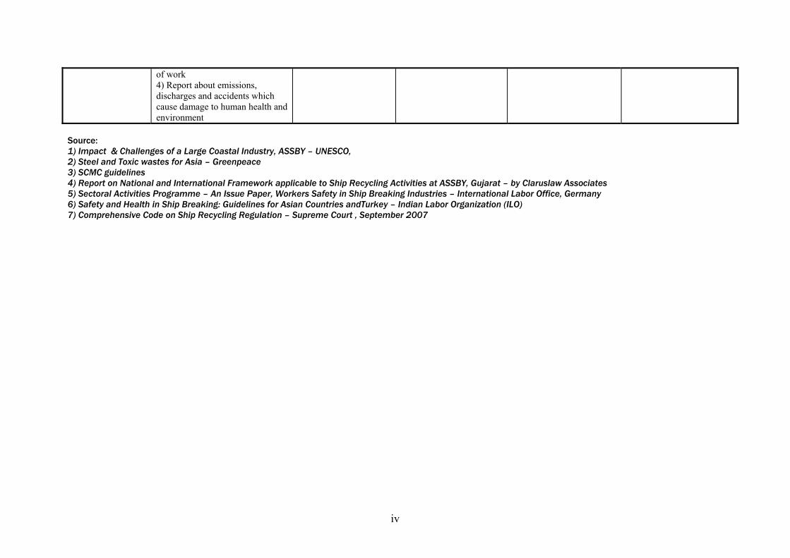
iv
of work
4) Report about emissions,
discharges and accidents which
cause damage to human health and
environment
Source: 1) Impact & Challenges of a Large Coastal Industry, ASSBY – UNESCO, 2) Steel and Toxic wastes for Asia – Greenpeace 3) SCMC guidelines 4) Report on National and International Framework applicable to Ship Recycling Activities at ASSBY, Gujarat – by Claruslaw Associates 5) Sectoral Activities Programme – An Issue Paper, Workers Safety in Ship Breaking Industries – International Labor Office, Germany 6) Safety and Health in Ship Breaking: Guidelines for Asian Countries andTurkey – Indian Labor Organization (ILO) 7) Comprehensive Code on Ship Recycling Regulation – Supreme Court , September 2007

ANNEXURE II List of Hazardous Materials and Substances that are Applicable to
Ship Breaking

i
Source: “Report of the Committee of Technical Experts on Ship Breaking Activities”, Writ Petition No.657 of 1995, MoEF, Supreme Court Monitoring Committee.
Table 1: Hazardous Materials that may be inherent in the Ship Structure
Metals consisting of alloys of any of the following:
Antimony * alloys with lead in lead-acid storage batteries, solder
Beryllium * hardening agent in alloys, fuel containers, navigational systems
Cadmium * bearings
Lead connectors, couplings, bearings
Mercury thermometers, bearing pressure sensors
Tellurium * in alloys
Antimony; antimony compounds * fire retardation in plastics, textiles, rubber etc.,
Cadmium; cadmium compounds batteries, anodes, bolts and nuts
Lead; lead compounds batteries, paint coatings, cable insulation
Arsenic; arsenic compound Paints on the ships‘ structure
Mercury; mercury compounds thermometers, light fittings, level switches
Hexavalent chromium compounds paints (lead chromate) on the ships‘ structure
Zinc residues, containing lead and cadmium in concentrations sufficient to exhibit characteristics exceeding norms of Schedule-2 of HW (M & H) Rules.
anodes (Cu, Cd, Pb, Zn)
Lead-acid batteries, whole or crushed batteries: emergency, radio, fire alarm, start up, lifeboats
** Electrical and electronic assemblies or scrap containing components such as accumulators and other batteries mercury-switches, glass from cathode-ray tubes and other activated glass and PCB-capacitors, or contaminated with I constituents (e.g., cadmium, mercury, lead, polychlorinated biphenyl) to an extent that they possess any of the characteristics contained in HW (M&H) Rules, Schedule-2
level switches, light tubes and fittings (capacitors), electrical cables
Materials containing principally inorganic constituents, which may contain metals and organic materials
Glass from cathode-ray tubes and other activated glasses TV and computer screens
Asbestos (dusts and fibres) thermal insulation, surfacing material, sound insulation

ii
Materials containing principally organic constituents, which may contain metals and inorganic materials
Mineral oils unfit for their originally intended use hydraulic fluids, oil sump (engine, lub. oil, gear, separator, etc.), oil tank, residuals (cargo residues)
antifreeze fluids
Substances and articles containing, consisting of or contaminated with polychlorinated biphenyl (PCB), polychlorinated terphenyl (PCT), polychlorinated naphthalene (PCN) or polybrominated biphenyl (PBB), or any other polybrominated analogues of these compounds, at a concentration level of 50 mg/kg or more
capacitors in light fittings, PCB in oil residuals, gaskets, couplings, wiring (plastics inherent in the ships‘ structure)
Materials containing either inorganic or organic constituents
Materials from the production, formulation and use of biocides and phytopharmaceuticals, including pesticides and herbicides which are off-specification, outdated, or unfit for their originally intended use, oils/water, hydrocarbons/water mixtures, emulsions.
paints and rust stabilizers, tin-based anti fouling coatings on ships‘ bottoms sludge, chemicals in water, tank residuals, bilge water
Materials from the production, formulation and use of inks, dyes, pigments, paints, lacquers, varnish
paints and coatings on the ships‘ structure
Materials of explosive nature as per HW (M&H) Rules, l989, Schedule-3
compressed gases (acetylene, propane, butane), cargo residues (cargo tanks)
Packages and containers containing substances in concentrations sufficient to exhibit characteristics as per HW (M&H) Rules, Schedule-2
cargo residues
Notes:
* For specification of wastes, refer Hazardous Waste (Management & Handling) Rule, 1989 and further amendments
made in the year 2000 & 2003, notified by MoEF, GoI.
** If the component is present it is most likely bound in an alloy or present at a very low concentration.
Table 2: Hazardous Materials and Substances that may be on Board the Ship
Unsorted batteries constituents to an extent to render them hazardous
portable radios, torches
Materials non-halogenated organic solvents solvents and thinners
Materials halogenated organic solvents solvents and thinners
Materials from the production, preparation and use of pharmaceutical products
miscellaneous medicines
Materials from the production, formulation and use of biocides and phytopharmaceuticals, including waste pesticides and herbicides which are off-specification, outdated, or unfit for their originally intended use.
insecticide sprays
Materials from the production, formulation and use of paints and coatings

iii
inks, dyes, pigments, paints, lacquers, varnish
Materials consisting of or containing off specification or outdated chemicals corresponding to categories and exhibiting hazard characteristics as per HW (M&H) Rules, 1989
consumables
Table 3: Other Hazardous Materials that are Relevant to Ship Recycling
CFC (R12 - dichlorodifluoromethane, or R22 - chlorodifluoromethane)
Refrigerants, Styrofoam
Halons Fire fighting equipment
Radioactive material Liquid-level indicators, smoke detectors,
Emergency signs
Microorganisms/ sediments ballast water systems (incl. tanks)
Fuel oil, diesel oil, gas oil

ANNEXURE III Main Items of Ships and Substances of Concern with Disposal
Options
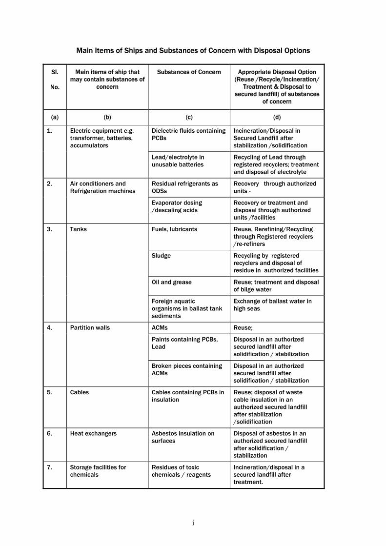
i
Dielectric fluids containing PCBs
Incineration/Disposal in Secured Landfill after stabilization /solidification
1. Electric equipment e.g. transformer, batteries, accumulators
Lead/electrolyte in unusable batteries
Recycling of Lead through registered recyclers; treatment and disposal of electrolyte
Residual refrigerants as ODSs
Recovery through authorized units
2. Air conditioners and Refrigeration machines
Evaporator dosing /descaling acids
Recovery or treatment and disposal through authorized units /facilities
Fuels, lubricants Reuse, Rerefining/Recycling through Registered recyclers /re-refiners
Sludge Recycling by registered recyclers and disposal of residue in authorized facilities
Oil and grease Reuse; treatment and disposal of bilge water
3. Tanks
Foreign aquatic organisms in ballast tank sediments
Exchange of ballast water in high seas
ACMs Reuse;
Paints containing PCBs, Lead
Disposal in an authorized secured landfill after solidification / stabilization
4. Partition walls
Broken pieces containing ACMs
Disposal in an authorized secured landfill after solidification / stabilization
5. Cables Cables containing PCBs in insulation
Reuse; disposal of waste cable insulation in an authorized secured landfill after stabilization /solidification
6. Heat exchangers Asbestos insulation on surfaces
Disposal of asbestos in an authorized secured landfill after solidification / stabilization
7. Storage facilities for chemicals
Residues of toxic chemicals / reagents
Incineration/disposal in a secured landfill after treatment.
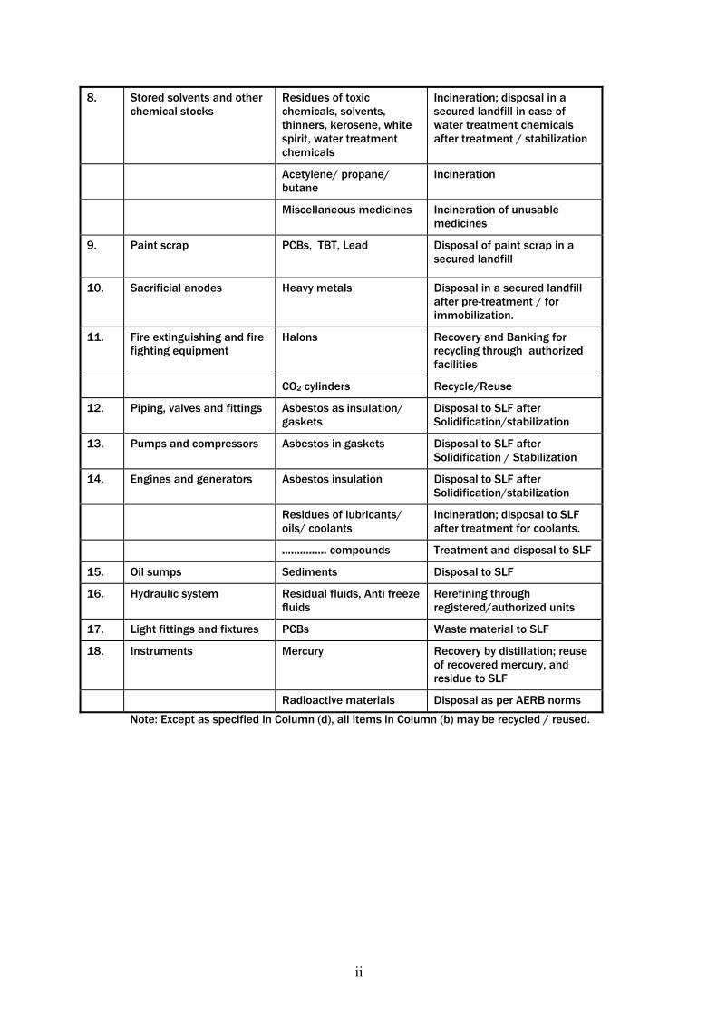
ii
8. Stored solvents and other chemical stocks
Residues of toxic chemicals, solvents, thinners, kerosene, white spirit, water treatment chemicals
Incineration; disposal in a secured landfill in case of water treatment chemicals after treatment / stabilization
Acetylene/ propane/ butane
Incineration
Miscellaneous medicines Incineration of unusable medicines
9. Paint scrap PCBs, TBT, Lead
Disposal of paint scrap in a secured landfill
10. Sacrificial anodes Heavy metals Disposal in a secured landfill after pre-treatment / for immobilization.
11. Fire extinguishing and fire fighting equipment
Halons Recovery and Banking for recycling through authorized facilities
CO2 cylinders Recycle/Reuse
12. Piping, valves and fittings Asbestos as insulation/ gaskets
Disposal to SLF after Solidification/stabilization
13. Pumps and compressors Asbestos in gaskets Disposal to SLF after Solidification / Stabilization
14. Engines and generators Asbestos insulation Disposal to SLF after Solidification/stabilization
Residues of lubricants/ oils/ coolants
Incineration; disposal to SLF after treatment for coolants.
compounds Treatment and disposal to SLF
15. Oil sumps Sediments Disposal to SLF
16. Hydraulic system Residual fluids, Anti freeze fluids
Rerefining through registered/authorized units
17. Light fittings and fixtures PCBs Waste material to SLF
18. Instruments Mercury Recovery by distillation; reuse of recovered mercury, and residue to SLF
Radioactive materials Disposal as per AERB norms
Note: Except as specified in Column (d), all items in Column (b) may be recycled / reused.
ANNEXURE IV
Preventive Measures for Environmental Elements of Concern

i
Air Water
Both within the yards while handling materials containing asbestos
Wet methods for Extraction, Consolidation for volume
reductions in enclosed chambers, Removal methods (glove bags, mini
enclosures and masks), Inspection procedures, training
requirements Solidification and stabilization
followed by final disposal in secured Landfill
Air Soil
Within the yard while handling materials containing PCBs
Within the
yard while handling liquid PCBs
Identifying and labeling suspect materials and equipment
Carefully removing all PCB containing materials, and transporting to dedicated area
Disposing in controlled manner PCB containing materials shall be
carefully removed, without use of heat inducing equipment (such as torches)
Keeping fire-extinguishing equipment nearby
Air Surface
water
Inhalation stripping/removal of particulates
Runoff
Create a separate area for paint-removal operations, with impermeable floor
Collect and contain all solid wastes resulting from paint removal process
Provide adequate storage/disposal facilities
Provide adequate storm water discharge facilities, to avoid contamination of storm water runoff
Soil
Within the yard and
Marine
Environment
Concrete pavement with collection system
Ground water / Surface water
GW – Seeps in the yard
SW - through
runoff
Concrete pavement with collection system
Soil Marine
water
Within the yard - Leakage in tanks containing ballast water
Determining pollutant concentrations prior to removal of the water
Adequate containment and pumping equipment
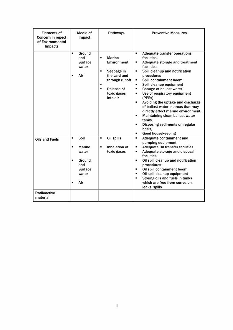
ii
Ground and Surface water
Air
Marine
Environment Seepage in
the yard and through runoff
Release of
toxic gases into air
Adequate transfer operations facilities
Adequate storage and treatment facilities
Spill cleanup and notification procedures
Spill containment boom Spill cleanup equipment Change of ballast water Use of respiratory equipment
(PPEs) Avoiding the uptake and discharge
of ballast water in areas that may directly effect marine environment,
Maintaining clean ballast water tanks,
Disposing sediments on regular basis,
Good housekeeping
Soil Marine
water Ground
and Surface water
Air
Oil spills Inhalation of
toxic gases
Adequate containment and pumping equipment
Adequate Oil transfer facilities Adequate storage and disposal
facilities Oil spill cleanup and notification
procedures Oil spill containment boom Oil spill cleanup equipment Storing oils and fuels in tanks
which are free from corrosion, leaks, spills
ANNEXURE V General Standards for Discharge of Environmental Pollutants
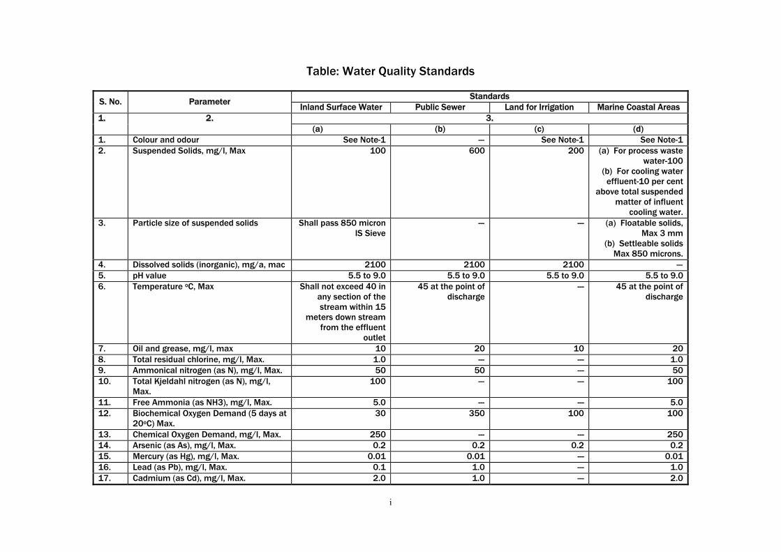
i
Table: Water Quality Standards
1. Colour and odour See Note-1 --- See Note-1 See Note-1
2. Suspended Solids, mg/l, Max 100 600 200 (a) For process waste water-100
(b) For cooling water effluent-10 per cent
above total suspended matter of influent
cooling water.
3. Particle size of suspended solids Shall pass 850 micron IS Sieve
--- --- (a) Floatable solids, Max 3 mm
(b) Settleable solids Max 850 microns.
4. Dissolved solids (inorganic), mg/a, mac 2100 2100 2100 ---
5. pH value 5.5 to 9.0 5.5 to 9.0 5.5 to 9.0 5.5 to 9.0
6. Temperature oC, Max Shall not exceed 40 in any section of the stream within 15
meters down stream from the effluent
outlet
45 at the point of discharge
--- 45 at the point of discharge
7. Oil and grease, mg/l, max 10 20 10 20
8. Total residual chlorine, mg/l, Max. 1.0 --- --- 1.0
9. Ammonical nitrogen (as N), mg/l, Max. 50 50 --- 50
10. Total Kjeldahl nitrogen (as N), mg/l, Max.
100 --- --- 100
11. Free Ammonia (as NH3), mg/l, Max. 5.0 --- --- 5.0
12. Biochemical Oxygen Demand (5 days at 20oC) Max.
30 350 100 100
13. Chemical Oxygen Demand, mg/l, Max. 250 --- --- 250
14. Arsenic (as As), mg/l, Max. 0.2 0.2 0.2 0.2
15. Mercury (as Hg), mg/l, Max. 0.01 0.01 --- 0.01
16. Lead (as Pb), mg/l, Max. 0.1 1.0 --- 1.0
17. Cadmium (as Cd), mg/l, Max. 2.0 1.0 --- 2.0
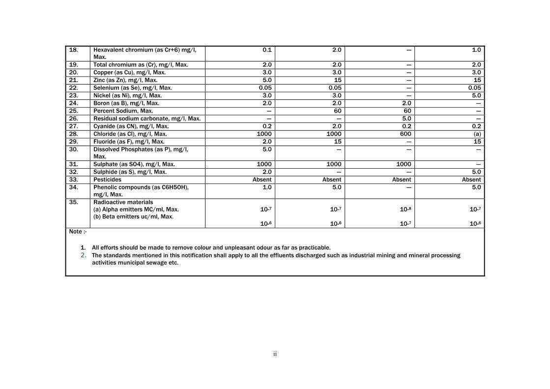
ii
18. Hexavalent chromium (as Cr+6) mg/l, Max.
0.1 2.0 --- 1.0
19. Total chromium as (Cr), mg/l, Max. 2.0 2.0 --- 2.0
20. Copper (as Cu), mg/l, Max. 3.0 3.0 --- 3.0
21. Zinc (as Zn), mg/l, Max. 5.0 15 --- 15
22. Selenium (as Se), mg/l, Max. 0.05 0.05 --- 0.05
23. Nickel (as Ni), mg/l, Max. 3.0 3.0 --- 5.0
24. Boron (as B), mg/l, Max. 2.0 2.0 2.0 ---
25. Percent Sodium, Max. --- 60 60 ---
26. Residual sodium carbonate, mg/l, Max. --- --- 5.0 ---
27. Cyanide (as CN), mg/l, Max. 0.2 2.0 0.2 0.2
28. Chloride (as Cl), mg/l, Max. 1000 1000 600 (a)
29. Fluoride (as F), mg/l, Max. 2.0 15 --- 15
30. Dissolved Phosphates (as P), mg/l, Max.
5.0 --- --- ---
31. Sulphate (as SO4), mg/l, Max. 1000 1000 1000 ---
32. Sulphide (as S), mg/l, Max. 2.0 --- --- 5.0
33. Pesticides Absent Absent Absent Absent
34. Phenolic compounds (as C6H5OH), mg/l, Max.
1.0 5.0 --- 5.0
35. Radioactive materials (a) Alpha emitters MC/ml, Max. (b) Beta emitters uc/ml, Max.
10-7
10-6
10-7
10-6
10-8
10-7
10-7
10-6
Note :-
1. All efforts should be made to remove colour and unpleasant odour as far as practicable.
2. The standards mentioned in this notification shall apply to all the effluents discharged such as industrial mining and mineral processing activities municipal sewage etc.

i
Ambient air quality standards in respect of noise
Area Code Category of Area Limits in dB (A) Leq
Day Time Night Time
(A) Industrial area 75 70
(B) Commercial area 65 55
(C) Residential area 55 45
(D) Silence zone 50 40
Note : 1. Day time is reckoned in between 6.00 AM and 9.00 PM 2. Night time is reckoned in between 9.00 PM and 6.00 AM 3. Silence zone is defined as areas upto 100 meters around such premises as hospitals,
educational institutions and courts. The Silence zones are to be declared by the Competent Authority.
4. Use of vehicular horns, loudspeakers and bursting of crackers shall be banned in these zones.
5. Mixed categories of areas should be declared as one of the four above mentioned categories by the Competent Authority and the corresponding standards shall apply.
The total sound power level, Lw, of a DG set should be less than, 94+10 log10 (KVA), dB (A), at the
manufacturing stage, where, KVA is the nominal power rating of a DG set.
This level should fall by 5 dB (A) every five years, till 2007, i.e. in 2002 and then in 2007.
Noise from the DG set should be controlled by providing an acoustic enclosure or by treating the room
acoustically.
The acoustic enclosure/acoustic treatment of the room should be designed for minimum 25 dB(A) Insertion
Loss or for meeting the ambient noise standards, whichever is on the higher side (if the actual ambient noise
is on the higher side, it may not be possible to check the performance of the acoustic enclosure/acoustic
treatment. Under such circumstances the performance may be checked for noise reduction upto actual
ambient noise level, preferably, in the night time). The measurement for Insertion Loss may be done at
different points at 0.5m from the acoustic enclosure/room, and then averaged.
The DG set should also be provide with proper exhaust muffler with Insertion Loss of minimum 25 dB(A).
1. The manufacturer should offer to the user a standard acoustic enclosure of 25 dB(A) Insertion Loss
and also a suitable exhaust muffler with Insertion Loss of 25 dB(A).
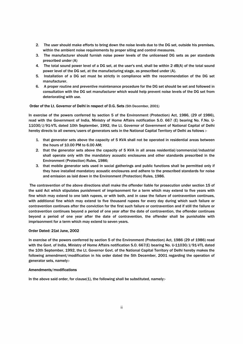
ii
2. The user should make efforts to bring down the noise levels due to the DG set, outside his premises,
within the ambient noise requirements by proper siting and control measures.
3. The manufacturer should furnish noise power levels of the unlicensed DG sets as per standards
prescribed under (A)
4. The total sound power level of a DG set, at the user's end, shall be within 2 dB(A) of the total sound
power level of the DG set, at the manufacturing stage, as prescribed under (A).
5. Installation of a DG set must be strictly in compliance with the recommendation of the DG set
manufacturer.
6. A proper routine and preventive maintenance procedure for the DG set should be set and followed in
consultation with the DG set manufacturer which would help prevent noise levels of the DG set from
deteriorating with use.
(5th December, 2001)
In exercise of the powers conferred by section 5 of the Environment (Protection) Act, 1986, (29 of 1986),
read with the Government of India, Ministry of Home Affairs notification S.O. 667 (E) bearing No. F.No. U-
11030/J/91-VTL dated 10th September, 1992, the Lt. Governor of Government of National Capital of Delhi
hereby directs to all owners/users of generators sets in the National Capital Territory of Delhi as follows :-
1. that generator sets above the capacity of 5 KVA shall not be operated in residential areas between
the hours of 10.00 PM to 6.00 AM;
2. that the generator sets above the capacity of 5 KVA in all areas residential/commercial/industrial
shall operate only with the mandatory acoustic enclosures and other standards prescribed in the
Environment (Protection) Rules, 1986;
3. that mobile generator sets used in social gatherings and public functions shall be permitted only if
they have installed mandatory acoustic enclosures and adhere to the prescribed standards for noise
and emission as laid down in the Environment (Protection) Rules, 1986.
The contravention of the above directions shall make the offender liable for prosecution under section 15 of
the said Act which stipulates punishment of imprisonment for a term which may extend to five years with
fine which may extend to one lakh rupees, or with both, and in case the failure of contravention continues,
with additional fine which may extend to five thousand rupees for every day during which such failure or
contravention continues after the conviction for the first such failure or contravention and if still the failure or
contravention continues beyond a period of one year after the date of contravention, the offender continues
beyond a period of one year after the date of contravention, the offender shall be punishable with
imprisonment for a term which may extend to seven years.
In exercise of the powers conferred by section 5 of the Environment (Protection) Act, 1986 (29 of 1986) read
with the Govt. of India, Ministry of Home Affairs notification S.O. 667(E) bearing No. U-11030/J/91-VTL dated
the 10th September, 1992, the Lt. Governor Govt. of the National Capital Territory of Delhi hereby makes the
following amendment/modification in his order dated the 5th December, 2001 regarding the operation of
generator sets, namely:-
In the above said order, for clause(1), the following shall be substituted, namely:-

iii
“(1) that the generator sets above 5KVA shall not be operated in residentoal areas between the hours from
10.00 p.m. to 6.00 a.m. except generator sets of Group Housing Societies and Multi-storey residential
apartments”.
The minimum height of stack to be provided with each generator set can be worked out using the following
formula:
H = h + 0.2 x OKVA
H = Total height of stack in metre
h = Height of the building in metres where the generator set is installed
KVA = Total generator capacity of the set in KVA
Based on the above formula the minimum stack height to be provided with different range of generator sets
may be categorized as follows:
For Generator Sets Total Height of stack in metre
50 KVA Ht. of the building + 1.5 metre
50-100 KVA Ht. of the building + 2.0 metre
100- 150 KVA Ht. of the building + 2.5 metre
150-200 KVA Ht. of the building + 3.0 metre
200-250 KVA Ht. of the building + 3.5 metre
250-300 KVA Ht. of the building + 3.5 metre
Similarly for higher KVA ratings a stack height can be worked out using the above formula
Source: Evolved By CPCB
[Emission Regulations Part IV: COINDS/26/1986-87]

ANNEXURE VI Densities for Different Types of Waste

i
Densities for Different Types of Waste
Asbestos 350 0.35
Glasswool 58 0.06
Sludge residue & Contaminated Materials
1000 1.00
Plastics and cables (with Paint chips)
830 0.83
Rubber 480 0.48
Fiberglass 1600 1.60
Rexene 560 0.56
Iron Scales 7000 7.00
Chicken mesh 1750 1.75
Cardboard and packing material
690 0.69
Glass 2400 2.40
Cement tiles 1450 1.45
Thermacole 19 0.02
MSW landfill 500 0.50

ANNEXURE VII Legal Instruments
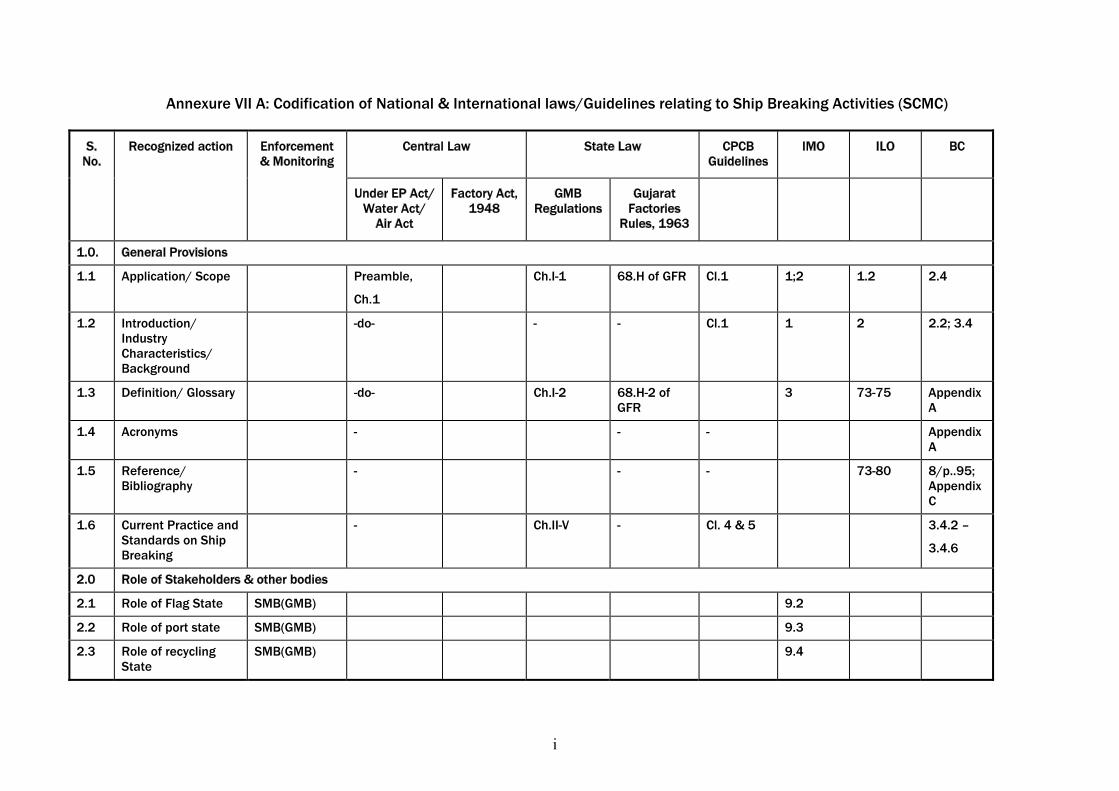
i
Annexure VII A: Codification of National & International laws/Guidelines relating to Ship Breaking Activities (SCMC)
1.1 Application/ Scope Preamble,
Ch.1
Ch.I-1 68.H of GFR Cl.1 1;2 1.2 2.4
1.2 Introduction/ Industry Characteristics/ Background
-do- - - Cl.1 1 2 2.2; 3.4
1.3 Definition/ Glossary -do- Ch.I-2 68.H-2 of GFR
3 73-75 Appendix A
1.4 Acronyms - - - Appendix A
1.5 Reference/ Bibliography
- - - 73-80 8/p..95; Appendix C
1.6 Current Practice and Standards on Ship Breaking
- Ch.II-V - Cl. 4 & 5 3.4.2 –
3.4.6
2.1 Role of Flag State SMB(GMB) 9.2
2.2 Role of port state SMB(GMB) 9.3
2.3 Role of recycling State
SMB(GMB) 9.4
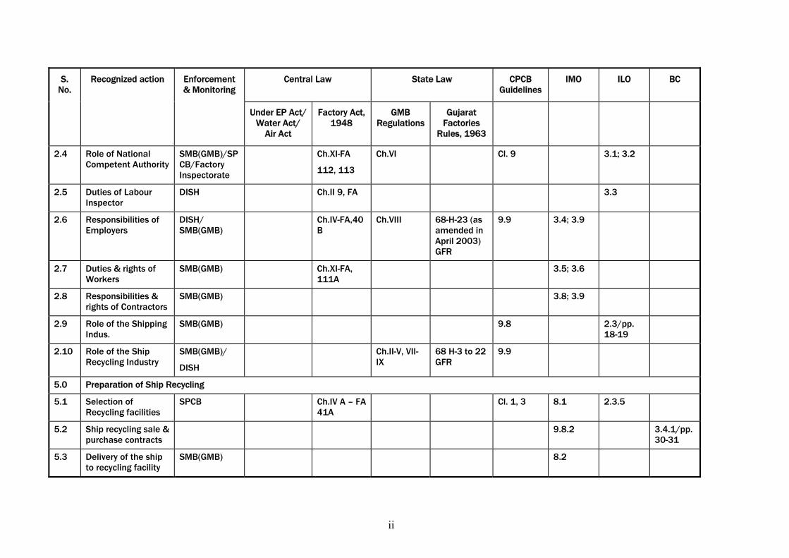
ii
2.4 Role of National Competent Authority
SMB(GMB)/SPCB/Factory Inspectorate
Ch.XI-FA
112, 113
Ch.VI Cl. 9 3.1; 3.2
2.5 Duties of Labour Inspector
DISH Ch.II 9, FA 3.3
2.6 Responsibilities of Employers
DISH/ SMB(GMB)
Ch.IV-FA,40 B
Ch.VIII 68-H-23 (as amended in April 2003) GFR
9.9 3.4; 3.9
2.7 Duties & rights of Workers
SMB(GMB) Ch.XI-FA, 111A
3.5; 3.6
2.8 Responsibilities & rights of Contractors
SMB(GMB) 3.8; 3.9
2.9 Role of the Shipping Indus.
SMB(GMB) 9.8 2.3/pp. 18-19
2.10 Role of the Ship Recycling Industry
SMB(GMB)/
DISH
Ch.II-V, VII-IX
68 H-3 to 22 GFR
9.9
5.1 Selection of Recycling facilities
SPCB Ch.IV A – FA 41A
Cl. 1, 3 8.1 2.3.5
5.2 Ship recycling sale & purchase contracts
9.8.2 3.4.1/pp. 30-31
5.3 Delivery of the ship to recycling facility
SMB(GMB) 8.2
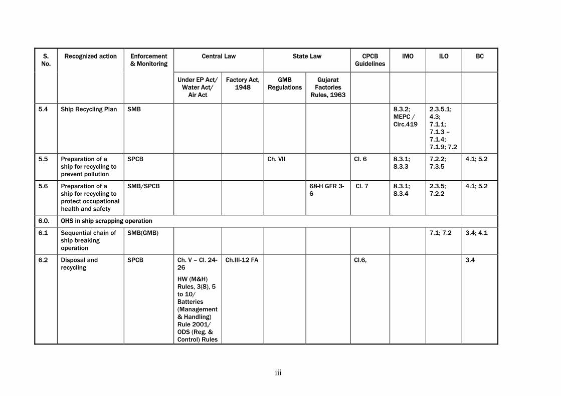
iii
5.4 Ship Recycling Plan SMB 8.3.2; MEPC / Circ.419
2.3.5.1; 4.3; 7.1.1; 7.1.3 – 7.1.4; 7.1.9; 7.2
5.5 Preparation of a ship for recycling to prevent pollution
SPCB Ch. VII Cl. 6 8.3.1; 8.3.3
7.2.2; 7.3.5
4.1; 5.2
5.6 Preparation of a ship for recycling to protect occupational health and safety
SMB/SPCB 68-H GFR 3-6
Cl. 7 8.3.1; 8.3.4
2.3.5; 7.2.2
4.1; 5.2
6.1 Sequential chain of ship breaking operation
SMB(GMB) 7.1; 7.2 3.4; 4.1
6.2 Disposal and recycling
SPCB Ch. V – Cl. 24-26
HW (M&H) Rules, 3(8), 5 to 10/ Batteries (Management & Handling) Rule 2001/ ODS (Reg. & Control) Rules
Ch.III-12 FA Cl.6, 3.4

iv
2000
6.3 Hazard identification & risk assessment, exposure assessment
DISH, SPCB MSIHC Rules, Schedule-1
Cl. 8 4.2; 4.4.1 4.4; 7.3 4.2; 4.4
6.4 Review of risk assessment
GMB & DISH (on site)/District Authorities (off-site)
Cl. 8 4.3; 7.4
6.5 Preventive and protective measures
SPCB, DISH Ch.V, 24-26
Chp. IV – 22, 22A
Schedule XVII GFR (for asbestos)
Cl. 8
4.4; 7.5; 8
4.4
6.6 Occupational Hazards
DISH 2.4; 7.3
6.7 Potentially hazardous materials
SPCB HW (M&H) Rules, 3(14)
Appendix 1; Appendix 2
2.3.2; 7.2.2; 9 Annex IV, p.173 IMO Inventory
4.2
6.8 Processes of removing metals, oil & fuel, bilge and ballast water, paints and coatings, asbestos, PCBS, other waste streams
SPCB. DISH Sch. XVII GFR (Asbestos)
Cl. 6 4.2; 4.1
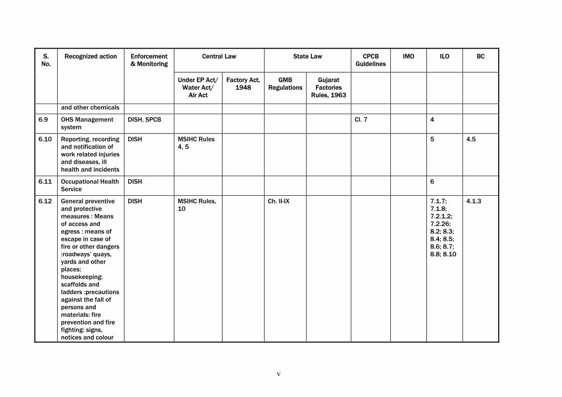
v
and other chemicals
6.9 OHS Management system
DISH, SPCB Cl. 7 4
6.10 Reporting, recording and notification of work related injuries and diseases, ill health and incidents
DISH MSIHC Rules 4, 5
5 4.5
6.11 Occupational Health Service
DISH 6
6.12 General preventive and protective measures : Means of access and egress : means of escape in case of fire or other dangers :roadways’ quays, yards and other places: housekeeping: scaffolds and ladders :precautions against the fall of persons and materials: fire prevention and fire fighting: signs, notices and colour
DISH MSIHC Rules, 10
Ch. II-IX 7.1.7; 7.1.8; 7.2.1.2; 7.2.26; 8.2; 8.3; 8.4; 8.5; 8.6; 8.7; 8.8; 8.10
4.1.3

vi
codes: prevention of unauthorized entry
6.13 Safe working practices and procedures of hat work (hot work safe certification), entry into enclosed spaces onboard ships (gas free certificate) and for avoiding accidental structural collapses
Dept. of Explosives or authorized agency; DISH
Ch. V 68-H 3 to 23 - GFR
9.4.3.2 7.2.2.6; 7.2.3,8.9;4.2.1;13.4
4.2.1
6.14 Recommendation for entering enclosed spaces aboard ships
DISH, SMB Appendix 5
7.2.2.7; 8.9;
4.1
6.15 General provision for the management and assessment of hazardous substances
SPCB HW (M&H) Rules, 3(x)
4.2;
6.16 Monitoring in the work place for chemical hazard
DISH MSIHC Rules, Sch.3
9.3 4.3;4.4
6.17 Preventive and protective measures against chemical hazards
DISH CA (EP, P&R) Rules
9.4 4.4

vii
6.18 Chemical safety data sheets
DISH MSIHC Rules Sch. 9
FA – Ch. IVA – 41F
9.5
6.19 Workers health surveillance
SMB FA-Ch. IV A – 41C; Ch. IX – 91A
6.5; 7.1.3; 9.6;10.2.6;10.3.3;10.4.2;10.5.2;10.6
4.1.3
6.20 Surveillance of work environment
SMB, SPCB Ch. IX – 91; Cl. 9 6.6; 7.1.5
6.21 Measures against physical hazards: noise, vibration, optical radiation, heat stress & wet condition, lighting, electricity
DISH 10; 10.2; 10.3; 10.4; 10.5; 10.6; 10.7
4.3
6.22 Measures against biological hazards
SPCB 11 4.2
6.23 Ergonomics and psychological hazards
SMB, DISH 12
6.24 Safety requirements for tools, machines and equipment; hand and electrical tools, flame cutting and other hot work,
DISH Ch. IV, FA – 21 to 26; 28 to 40
6.7; 13.1; 13.2; 13.3; 13.4; 13.5; 13.6;

viii
gas cylinder, power generators, lifting appliances and gear, lifting ropes, transport facilities
13.7; 13.8; 13.9
6.25 Competence and training; qualification of manager, supervisor, worker, contractor and other third party
SMB GFR Amendment Rule 2002
8.8; 10.7.7; 11; 14; 14.2; 14.3; 14.4
6.26 Personal protective equipment and clothing
DISH, SMB Circular
Gmb/Env/23/ Alang-GM/ 11940 dated 17-03-2006
15 5.2
6.27 Contingency and emergency preparedness, first aid, rescue
SMB MSIHC Rules 13, 14, 15, 16, 17
Cl. 8 4.6; 16 4.5
6.28 Special protection, employment & social insurance, working Hours, night work, child labour,alcohol & drug related
SMB FA – Ch. VI; Ch. VII
17; 17.2; 17.3; 17.4; 17.5; 17.6

ix
problem, HV/AIDS
6.29 Welfare :
Drinking water, sanitary & washing facilities, cloak room, shelters and facili-ties for food and drink, housing
SMB FA – Ch. V Ch. IX 18
7.1 Waste stream SPCB 7.2.4 2;3.3;3.4; 4.2
7.2 Hazardous substances and other substances of general concern to the environment (types of release)
SPCB 4.2; appendix B
7.3 Monitoring programme for the surrounding ground / groundwater, seawater / sediments and air, noise and vibrations
SPCB 4.3
7.4 Achieving environmentally sound management
SMB & SPCB 9.5.1 6;7.2
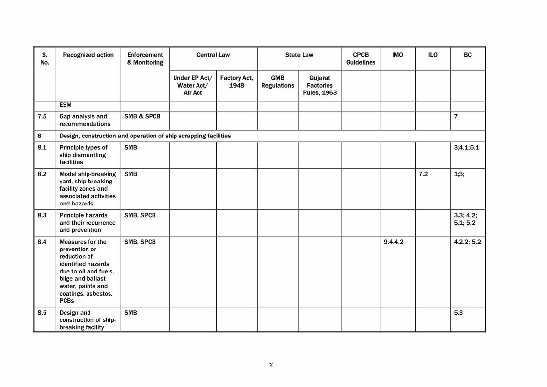
x
ESM
7.5 Gap analysis and recommendations
SMB & SPCB 7
8.1
Principle types of ship dismantling facilities
SMB 3;4.1;5.1
8.2 Model ship-breaking yard, ship-breaking facility zones and associated activities and hazards
SMB 7.2 1;3;
8.3 Principle hazards and their recurrence and prevention
SMB, SPCB 3.3; 4.2; 5.1; 5.2
8.4 Measures for the prevention or reduction of identified hazards due to oil and fuels, bilge and ballast water, paints and coatings, asbestos, PCBs
SMB, SPCB 9.4.4.2 4.2.2; 5.2
8.5 Design and construction of ship-breaking facility
SMB 5.3

xi
zones
8.6 Possible environmental, health and safety problems for ship breaking facility zones
SMB 7.2.4 5.3;
SMB : State Maritime Board SPCB : State Pollution Control Board DISH : Directorate of Industrial Safety & Health GMB : Gujarat Maritime Board HW (M & H) Rules : Hazardous Waste (Management & Handling) Rules FA : Factory Act, 1948 MISHC : Manufacture, Storage and Import of Hazardous Chemicals Rules GFR : Gujarat Factory Rules ODS : Ozone Depleting Substances

i
Annexure VII B: A Compilation of Legal Instruments (CPCB)
SL.
NO.
LEGAL INSTRUMENT
(TYPE, REFERENCE,
YEAR)
RESPONSIBLE
MINISTRIES OR
BODIES
CHEMICAL USE
CATEGORIES/
POLLUTANTS
OBJECTIVE OF
LEGISLATION
RELEVANT ARTICLES/PROVISIONS
1 Air (Prevention and
Control of Pollution) Act,
1981 amended 1987
Central Pollution
Control Board and State
Pollution Control
Boards
Air pollutants from
chemical industries
The prevention, control and
abatement of air pollution
Section 2: Definitions
Section 21: Consent from State Boards
Section 22: Not to allow emissions
exceeding prescribed limits
Section 24: Power of Entry and Inspection
Section 25: Power to Obtain Information
Section 26: Power to Take Samples
Section 37-43: Penalties and Procedures
2 Air (Prevention and
Control of Pollution)
(Union Territories) Rules,
1983
Central Pollution
Control Board and State
Pollution Control
Boards
Air pollutants from
chemical industries
The prevention, control and
abatement of air pollution
Rule 2: Definitions
Rule 9: Consent Applications
3 Water (Prevention and
Control of Pollution) Act,
1974 amended 1988
Central Pollution
Control Board and State
Pollution Control
Boards
Water Pollutants from water
polluting industries
The prevention and control
of water pollution and also
maintaining or restoring the
wholesomeness of water
Section 2: Definitions
Section 20: Power to Obtain Information
Section 21: Power to Take Samples
Section 23: Power of Entry and Inspection
Section 24: Prohibition on Disposal
Section 25: Restriction on New Outlet and
New Discharge
Section 26: Provision regarding existing
discharge of sewage or trade effluent
Section 27: Refusal or withdrawal of
consent by state boards
Section 41-49: Penalties and Procedures
4 Water (Prevention and
Control of Pollution)
Rules, 1975
Central Pollution
Control Board and State
Pollution Control
Boards
Water Pollutants from water
polluting industries
The prevention and control
of water pollution and also
maintaining or restoring the
wholesomeness of water
Rule 2: Definitions
Rule 30: Power to take samples
Rule 32: Consent Applications
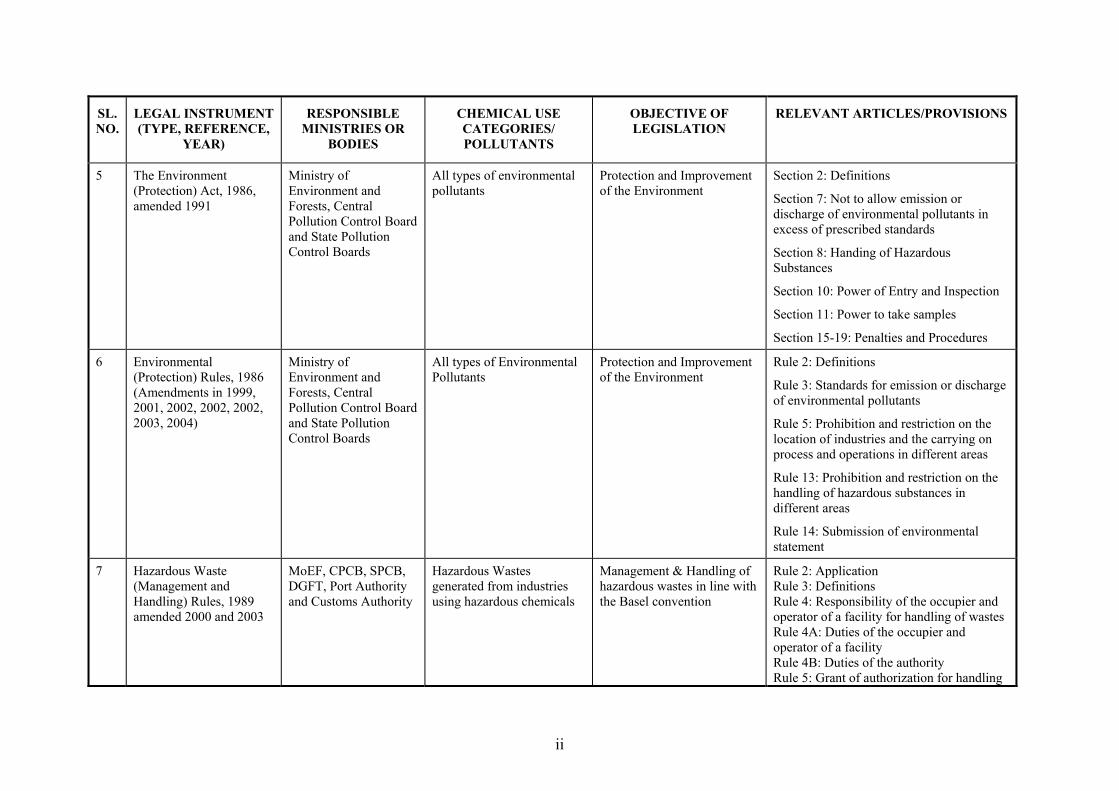
ii
SL.
NO.
LEGAL INSTRUMENT
(TYPE, REFERENCE,
YEAR)
RESPONSIBLE
MINISTRIES OR
BODIES
CHEMICAL USE
CATEGORIES/
POLLUTANTS
OBJECTIVE OF
LEGISLATION
RELEVANT ARTICLES/PROVISIONS
5 The Environment
(Protection) Act, 1986,
amended 1991
Ministry of
Environment and
Forests, Central
Pollution Control Board
and State Pollution
Control Boards
All types of environmental
pollutants
Protection and Improvement
of the Environment
Section 2: Definitions
Section 7: Not to allow emission or
discharge of environmental pollutants in
excess of prescribed standards
Section 8: Handing of Hazardous
Substances
Section 10: Power of Entry and Inspection
Section 11: Power to take samples
Section 15-19: Penalties and Procedures
6 Environmental
(Protection) Rules, 1986
(Amendments in 1999,
2001, 2002, 2002, 2002,
2003, 2004)
Ministry of
Environment and
Forests, Central
Pollution Control Board
and State Pollution
Control Boards
All types of Environmental
Pollutants
Protection and Improvement
of the Environment
Rule 2: Definitions
Rule 3: Standards for emission or discharge
of environmental pollutants
Rule 5: Prohibition and restriction on the
location of industries and the carrying on
process and operations in different areas
Rule 13: Prohibition and restriction on the
handling of hazardous substances in
different areas
Rule 14: Submission of environmental
statement
7 Hazardous Waste
(Management and
Handling) Rules, 1989
amended 2000 and 2003
MoEF, CPCB, SPCB,
DGFT, Port Authority
and Customs Authority
Hazardous Wastes
generated from industries
using hazardous chemicals
Management & Handling of
hazardous wastes in line with
the Basel convention
Rule 2: Application
Rule 3: Definitions
Rule 4: Responsibility of the occupier and
operator of a facility for handling of wastes
Rule 4A: Duties of the occupier and
operator of a facility
Rule 4B: Duties of the authority
Rule 5: Grant of authorization for handling
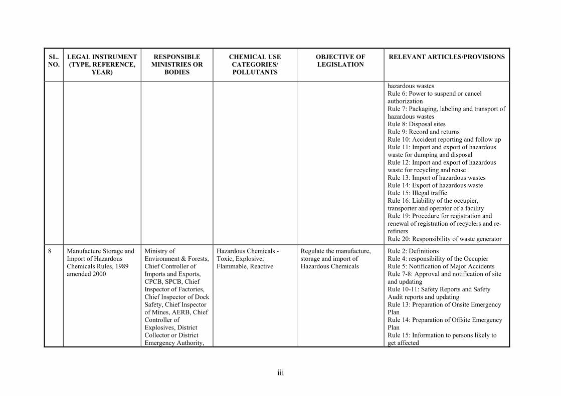
iii
SL.
NO.
LEGAL INSTRUMENT
(TYPE, REFERENCE,
YEAR)
RESPONSIBLE
MINISTRIES OR
BODIES
CHEMICAL USE
CATEGORIES/
POLLUTANTS
OBJECTIVE OF
LEGISLATION
RELEVANT ARTICLES/PROVISIONS
hazardous wastes
Rule 6: Power to suspend or cancel
authorization
Rule 7: Packaging, labeling and transport of
hazardous wastes
Rule 8: Disposal sites
Rule 9: Record and returns
Rule 10: Accident reporting and follow up
Rule 11: Import and export of hazardous
waste for dumping and disposal
Rule 12: Import and export of hazardous
waste for recycling and reuse
Rule 13: Import of hazardous wastes
Rule 14: Export of hazardous waste
Rule 15: Illegal traffic
Rule 16: Liability of the occupier,
transporter and operator of a facility
Rule 19: Procedure for registration and
renewal of registration of recyclers and re-
refiners
Rule 20: Responsibility of waste generator
8 Manufacture Storage and
Import of Hazardous
Chemicals Rules, 1989
amended 2000
Ministry of
Environment & Forests,
Chief Controller of
Imports and Exports,
CPCB, SPCB, Chief
Inspector of Factories,
Chief Inspector of Dock
Safety, Chief Inspector
of Mines, AERB, Chief
Controller of
Explosives, District
Collector or District
Emergency Authority,
Hazardous Chemicals -
Toxic, Explosive,
Flammable, Reactive
Regulate the manufacture,
storage and import of
Hazardous Chemicals
Rule 2: Definitions
Rule 4: responsibility of the Occupier
Rule 5: Notification of Major Accidents
Rule 7-8: Approval and notification of site
and updating
Rule 10-11: Safety Reports and Safety
Audit reports and updating
Rule 13: Preparation of Onsite Emergency
Plan
Rule 14: Preparation of Offsite Emergency
Plan
Rule 15: Information to persons likely to
get affected

iv
SL.
NO.
LEGAL INSTRUMENT
(TYPE, REFERENCE,
YEAR)
RESPONSIBLE
MINISTRIES OR
BODIES
CHEMICAL USE
CATEGORIES/
POLLUTANTS
OBJECTIVE OF
LEGISLATION
RELEVANT ARTICLES/PROVISIONS
CEES under DRDO Rule 16: Proprietary Information
Rule 17: Material Safety Data Sheets
Rule 18: Import of Hazardous Chemicals
9 Chemical Accidents
(Emergency Planning,
Preparedness and
Response) Rules, 1996
CCG, SCG, DCG, LCG
and MAH Units
Hazardous Chemicals -
Toxic, Explosive,
Flammable, Reactive
Emergency Planning
Preparedness and Response
to chemical accidents
Rule 2: Definitions
Rule 5: Functions of CCG
Rule 7: Functions of SCG
Rule 9: Functions of DCG
Rule 10: Functions of LCG
10 EIA Notification, 2006 MoEF, SPCB For all the identified
developmental activities
in the notification
Requirement of
environmental clearance
before establishment of or
modernization / expansion of
certain type of industries/
projects.
Requirements and procedure for
seeking environmental clearance of projects
11 Batteries (Management
and Handling) Rules,
2001.
SPCB, CPCB and
MoEF
Lead Acid Batteries To control the hazardous
waste generation (lead waste)
from used lead acid batteries
Rule 2: Application
Rule 3: Definitions
Rule 4: Responsibilities of manufacturer,
importer, assembler and re-conditioner
Rule 5: Registration of Importers
Rule 7: Responsibilities of dealer
Rule 8: Responsibilities of recycler
Rule 9: Procedure for registration / renewal
of registration of recyclers
Rule 10: Responsibilities of consumer or
bulk consumer
Rule 11: Responsibilities of auctioneer
Rule 14: Computerization of Records and
Returns
12 Public Liability Insurance
Act, 1991 amended 1992
Ministry of
Environment & Forests,
District Collector
Hazardous Substances To provide immediate relief
to persons affected by
accident involving hazardous
substances
Section 2: Definitions
Section 3: Liability to give relief in certain
cases on principle of no fault
Section 4: Duty of owner to take out

v
SL.
NO.
LEGAL INSTRUMENT
(TYPE, REFERENCE,
YEAR)
RESPONSIBLE
MINISTRIES OR
BODIES
CHEMICAL USE
CATEGORIES/
POLLUTANTS
OBJECTIVE OF
LEGISLATION
RELEVANT ARTICLES/PROVISIONS
insurance policy
Section 7A: Establishment of
Environmental Relief Fund
Section 14-18: Penalties and Offences
13 Public Liability Insurance
Rules, 1991 amended
1993
Ministry of
Environment & Forests,
District Collector
Hazardous Substances To provide immediate relief
to persons affected by
accident involving hazardous
substances and also for
Establishing an
Environmental Relief fund
Rule 2: Definitions
Rule 6: Establishment of administration of
fund
Rule 10: Extent of liability
Rule 11: Contribution of the owner to
environmental relief fund
14 Factories Act, 1948 Ministry of Labour,
DGFASLI and
Directorate of Industrial
Safety and
Health/Factories
Inspectorate
Chemicals as specified in
the Table
Control of workplace
environment, and providing
for good health and safety of
workers
Section 2: Interpretation
Section 6: Approval, licensing and
registration of factories
Section 7A: General duties of the occupier
Section 7B: General duties of
manufacturers etc., as regards articles and
substances for use in factories
Section 12: Disposal of wastes and effluents
Section 14: Dust and fume
Section 36: Precautions against dangerous
fumes, gases, etc.
Section 37: Explosion or inflammable dust,
gas, etc.
Chapter IVA: Provisions relating to
Hazardous processes
Section 87: Dangerous operations
Section 87A: Power to prohibit
employment on account of serious hazard
Section 88: Notice of certain accident
Section 88A: Notice of certain dangerous
occurrences
Chapter X: Penalties and procedures

vi
SL.
NO.
LEGAL INSTRUMENT
(TYPE, REFERENCE,
YEAR)
RESPONSIBLE
MINISTRIES OR
BODIES
CHEMICAL USE
CATEGORIES/
POLLUTANTS
OBJECTIVE OF
LEGISLATION
RELEVANT ARTICLES/PROVISIONS
15 The Explosives Act, 1884 Ministry of Commerce
and Industry
(Department of
Explosives)
Explosive substances as
defined under the Act
To regulate the manufacture,
possession, use, sale,
transport, export and import
of explosives with a view to
prevent accidents
Section 4: Definition
Section 6: Power for Central government to
prohibit the manufacture, possession or
importation of especially dangerous
explosives
Section 6B: Grant of Licenses
16 The Explosive Rules,
1983
Ministry of Commerce
and Industry and Chief
Controller of
Explosives, port
conservator, customs
collector, railway
administration
Explosive substances as
defined under the Act
To regulate the manufacture,
possession, use, sale,
transport, export and import
of explosives with a view to
prevent accidents
Rule 2: Definition
Chapter II: General Provisions
Chapter III: Import and Export
Chapter IV: Transport
Chapter V: Manufacture of explosives
Chapter VI: Possession sale and use
Chapter VII: Licenses
17 The Gas Cylinder Rules,
2004
Ministry of Commerce
and Industry and Chief
Controller of
Explosives, port
conservator, customs
collector, DGCA, DC,
DM, Police (sub
inspector to
commissioner)
Gases (Toxic, non toxic and
non flammable, non toxic
and flammable, Dissolved
Acetylene Gas, Non toxic
and flammable liquefiable
gas other than LPG, LPG
Regulate the import, storage,
handling and transportation
of gas cylinders with a view
to prevent accidents
Rule 2: Definition
Chapter II: General Provisions
Chapter III: Importation of Cylinder
Chapter IV: Transport of Cylinder
Chapter VII: Filling and Possession
18 The Custom Act, 1962 CBEC, Ministry of
Finance
Hazardous Goods To prevent entry of illegal
hazardous goods or banned
goods including hazardous or
banned chemicals
Section 2: definitions
Section 11: Power to Prohibit Importation
or Exportation of Goods
19 The Merchant Shipping
Act, 1958 amended in
2002 and 2003
Ministry of Shipping,
Road Transport and
Highways
All packaged cargo
including Dangerous and
hazardous goods as defined
in the rules
For safe handling and
transportation of cargo
including dangerous goods to
prevent accident
Section 3: Definitions
Section 331: Carriage of Dangerous Goods
20 Merchant Shipping Ministry of Shipping, All packaged cargo For safe handling and

vii
SL.
NO.
LEGAL INSTRUMENT
(TYPE, REFERENCE,
YEAR)
RESPONSIBLE
MINISTRIES OR
BODIES
CHEMICAL USE
CATEGORIES/
POLLUTANTS
OBJECTIVE OF
LEGISLATION
RELEVANT ARTICLES/PROVISIONS
(carriage of Cargo) Rules
1995
Road Transport and
Highways
including Dangerous and
hazardous goods as defined
in the rules
transportation of cargo
including dangerous goods to
prevent accident
21 The Indian Port Act, 1908 Ministry of Shipping,
Road Transport and
Highways
All Chemicals - handling
and storage
For control of activities on
ports including safety of
shipping and conservation of
ports
Section 2: Definitions
Chapter IV: Rules for the safety of shipping
and the conservation of ports
Chapter VII: Provisions with respect to
penalties
22 The Dock Workers,
(Safety, Health and
Welfare) Act, 1986
Ministry of Labour,
DGFASLI and
Directorate of Dock
Safety
All Chemicals termed as
dangerous goods
Safety of Dock workers
including handling of
dangerous goods
23 The Dock Workers,
(Safety, Health and
Welfare) Rules, 1990
Ministry of Labour,
DGFASLI and
Directorate of Dock
Safety
All Chemicals termed as
dangerous goods
Safety of Dock workers
including handling of
dangerous goods
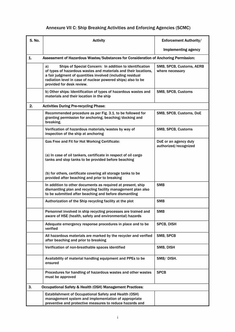
i
Annexure VII C: Ship Breaking Activities and Enforcing Agencies (SCMC)
a) Ships of Special Concern: In addition to identification of types of hazardous wastes and materials and their locations, a fair judgment of quantities involved (including residual radiation level in case of nuclear powered ships) also to be provided for desk review.
SMB, SPCB, Customs, AERB where necessary
b) Other ships: Identification of types of hazardous wastes and materials and their location in the ship
SMB, SPCB, Customs
Recommended procedure as per Fig. 3.1. to be followed for granting permission for anchoring, beaching/docking and breaking.
SMB, SPCB, Customs, DoE
Verification of hazardous materials/wastes by way of inspection of the ship at anchoring
SMB, SPCB, Customs
Gas Free and Fit for Hot Working Certificate:
(a) In case of oil tankers, certificate in respect of oil cargo tanks and slop tanks to be provided before beaching
(b) for others, certificate covering all storage tanks to be provided after beaching and prior to breaking
DoE or an agency duly authorized/recognized
In addition to other documents as required at present, ship dismantling plan and recycling facility management plan also to be submitted after beaching and before dismantling
SMB
Authorization of the Ship recycling facility at the plot SMB
Personnel involved in ship recycling processes are trained and aware of HSE (health, safety and environmental) hazards
SMB
Adequate emergency response procedures in place and to be verified
SPCB, DISH
All hazardous materials are marked by the recycler and verified after beaching and prior to breaking
SMB, SPCB
Verification of non-breathable spaces identified SMB, DISH
Availability of material handling equipment and PPEs to be ensured
SMB/ DISH.
Procedures for handling of hazardous wastes and other wastes must be approved
SPCB
Establishment of Occupational Safety and Health (OSH) management system and implementation of appropriate preventive and protective measures to reduce hazards and
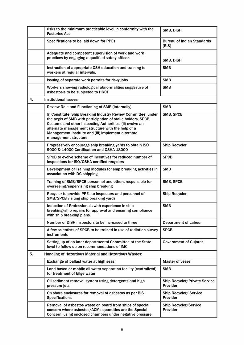
ii
risks to the minimum practicable level in conformity with the Factories Act
SMB, DISH
Specifications to be laid down for PPEs Bureau of Indian Standards (BIS)
Adequate and competent supervision of work and work practices by engaging a qualified safety officer.
SMB, DISH
Instruction of appropriate OSH education and training to workers at regular intervals.
SMB
Issuing of separate work permits for risky jobs SMB
Workers showing radiological abnormalities suggestive of asbestosis to be subjected to HRCT
SMB
Review Role and Functioning of SMB (Internally) SMB
(i) Constitute ‘Ship Breaking Industry Review Committee’ under the aegis of SMB with participation of stake holders, SPCB, Customs and other Inspecting Authorities, (ii) evolve an alternate management structure with the help of a Management Institute and (iii) implement alternate management structure
SMB, SPCB
Progressively encourage ship breaking yards to obtain ISO 9000 & 14000 Certification and OSHA 18000
Ship Recycler
SPCB to evolve scheme of incentives for reduced number of inspections for ISO/OSHA certified recyclers
SPCB
Development of Training Modules for ship breaking activities in association with DG shipping
SMB
Training of SMB/SPCB personnel and others responsible for overseeing/supervising ship breaking
SMB, SPCB
Recycler to provide PPEs to inspectors and personnel of SMB/SPCB visiting ship breaking yards
Ship Recycler
Induction of Professionals with experience in ship breaking/ship repairs for approval and ensuring compliance with ship breaking plans.
SMB
Number of DISH inspectors to be increased to three Department of Labour
A few scientists of SPCB to be trained in use of radiation survey instruments
SPCB
Setting up of an inter-departmental Committee at the State level to follow up on recommendations of IMC
Government of Gujarat
Exchange of ballast water at high seas Master of vessel
Land based or mobile oil water separation facility (centralized) for treatment of bilge water
SMB
Oil sediment removal system using detergents and high pressure jets
Ship Recycler/Private Service Provider
On shore enclosures for removal of asbestos as per BIS Specifications
Ship Recycler/ Service Provider
Removal of asbestos waste on board from ships of special concern where asbestos/ACMs quantities are the Special Concern, using enclosed chambers under negative pressure
Ship Recycler/Service Provider
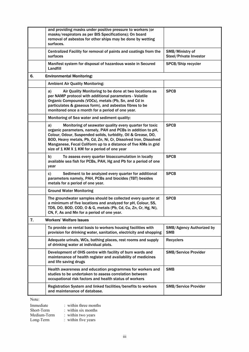
iii
and providing masks under positive pressure to workers (or masks/respirators as per BIS Specifications); On board removal of asbestos for other ships may be done by wetting surfaces.
Centralized Facility for removal of paints and coatings from the surfaces
SMB/Ministry of Steel/Private Investor
Manifest system for disposal of hazardous waste in Secured Landfill
SPCB/Ship recycler
Ambient Air Quality Monitoring:
a) Air Quality Monitoring to be done at two locations as per NAMP protocol with additional parameters - Volatile Organic Compounds (VOCs), metals (Pb, Sn, and Cd in particulates & gaseous form), and asbestos fibres to be monitored once a month for a period of one year.
SPCB
Monitoring of Sea water and sediment quality:
a) Monitoring of seawater quality every quarter for toxic organic parameters, namely, PAH and PCBs in addition to pH, Colour, Odour, Suspended solids, turbidity, Oil & Grease, DO, BOD, Heavy metals, Pb, Cd, Zn, Ni, Cr, Dissolved Iron, Dissolved Manganese, Fecal Coliform up to a distance of five KMs in grid size of 1 KM X 1 KM for a period of one year
SPCB
b) To assess every quarter bioaccumulation in locally available sea fish for PCBs, PAH, Hg and Pb for a period of one year
SPCB
c) Sediment to be analyzed every quarter for additional parameters namely, PAH, PCBs and biocides (TBT) besides metals for a period of one year.
SPCB
Ground Water Monitoring
The groundwater samples should be collected every quarter at a minimum of five locations and analyzed for pH, Colour, SS, TDS, DO, BOD, COD, O & G, metals (Pb, Cd, Cu, Zn, Cr, Hg, Ni), CN, F, As and Mn for a period of one year.
SPCB
To provide on rental basis to workers housing facilities with provision for drinking water, sanitation, electricity and shopping
SMB/Agency Authorized by SMB
Adequate urinals, WCs, bathing places, rest rooms and supply of drinking water at individual plots.
Recyclers
Development of OHS centre with facility of burn wards and maintenance of health register and availability of medicines and life saving drugs
SMB/Service Provider
Health awareness and education programmes for workers and studies to be undertaken to assess correlation between occupational risk factors and health status of workers
SMB
Registration System and linked facilities/benefits to workers and maintenance of database.
SMB/Service Provider
Note:
Immediate : within three months
Short-Term : within six months
Medium-Term : within two years
Long-Term : within five years

ANNEXURE VIII Form 1 (Application Form for Obtaining EIA Clearance)
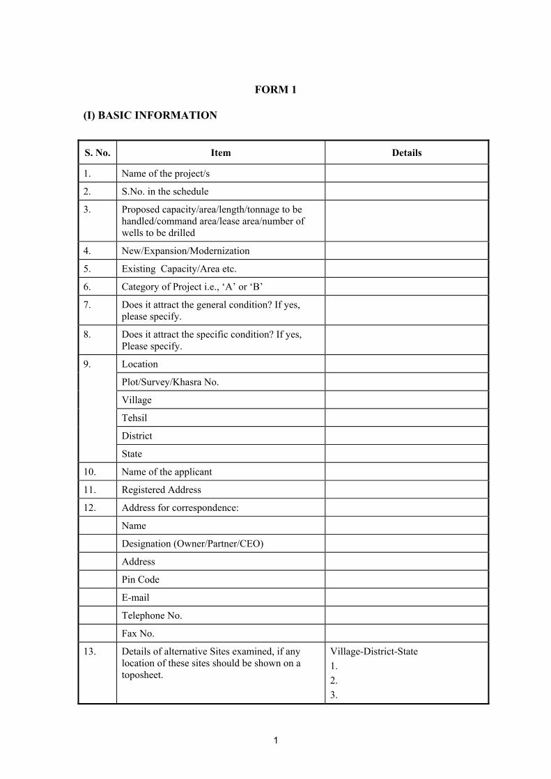
1
FORM 1
(I) BASIC INFORMATION
S. No. Item Details
1. Name of the project/s
2. S.No. in the schedule
3. Proposed capacity/area/length/tonnage to be
handled/command area/lease area/number of
wells to be drilled
4. New/Expansion/Modernization
5. Existing Capacity/Area etc.
6. Category of Project i.e., ‘A’ or ‘B’
7. Does it attract the general condition? If yes,
please specify.
8. Does it attract the specific condition? If yes,
Please specify.
Location
Plot/Survey/Khasra No.
Village
Tehsil
District
9.
State
10. Name of the applicant
11. Registered Address
12. Address for correspondence:
Name
Designation (Owner/Partner/CEO)
Address
Pin Code
Telephone No.
Fax No.
13. Details of alternative Sites examined, if any
location of these sites should be shown on a
toposheet.
Village-District-State
1.
2.
3.
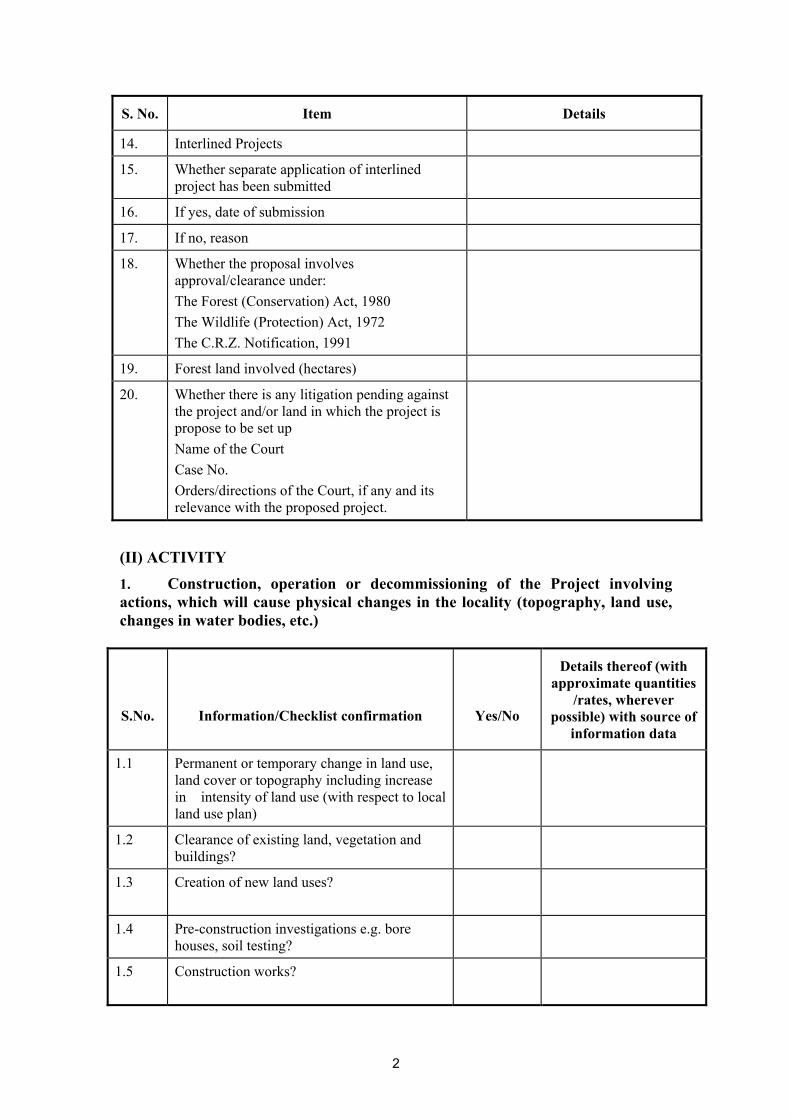
2
S. No. Item Details
14. Interlined Projects
15. Whether separate application of interlined
project has been submitted
16. If yes, date of submission
17. If no, reason
18. Whether the proposal involves
approval/clearance under:
The Forest (Conservation) Act, 1980
The Wildlife (Protection) Act, 1972
The C.R.Z. Notification, 1991
19. Forest land involved (hectares)
20. Whether there is any litigation pending against
the project and/or land in which the project is
propose to be set up
Name of the Court
Case No.
Orders/directions of the Court, if any and its
relevance with the proposed project.
(II) ACTIVITY
1. Construction, operation or decommissioning of the Project involving
actions, which will cause physical changes in the locality (topography, land use,
changes in water bodies, etc.)
S.No.
Information/Checklist confirmation
Yes/No
Details thereof (with
approximate quantities
/rates, wherever
possible) with source of
information data
1.1 Permanent or temporary change in land use,
land cover or topography including increase
in intensity of land use (with respect to local
land use plan)
1.2 Clearance of existing land, vegetation and
buildings?
1.3 Creation of new land uses?
1.4 Pre-construction investigations e.g. bore
houses, soil testing?
1.5 Construction works?

3
S.No.
Information/Checklist confirmation
Yes/No
Details thereof (with
approximate quantities
/rates, wherever
possible) with source of
information data
1.6 Demolition works?
1.7 Temporary sites used for construction works
or housing of construction workers?
1.8 Above ground buildings, structures or
earthworks including linear structures, cut
and fill or excavations
1.9 Underground works including mining or
tunneling?
1.10 Reclamation works?
1.11 Dredging?
1.12 Offshore structures?
1.13 Production and manufacturing processes?
1.14 Facilities for storage of goods or materials?
1.15 Facilities for treatment or disposal of solid
waste or liquid effluents?
1.16 Facilities for long term housing of operational
workers?
1.17 New road, rail or sea traffic during
construction or operation?
1.18 New road, rail, air waterborne or other
transport infrastructure including new or
altered routes and stations, ports, airports etc?
1.19 Closure or diversion of existing transport
routes or infrastructure leading to changes in
traffic movements?
1.20 New or diverted transmission lines or
pipelines?
1.21 Impoundment, damming, culverting,
realignment or other changes to the hydrology
of watercourses or aquifers?
1.22 Stream crossings?
1.23 Abstraction or transfers of water form ground
or surface waters?
1.24 Changes in water bodies or the land surface
affecting drainage or run-off?
1.25 Transport of personnel or materials for
construction, operation or decommissioning?

4
S.No.
Information/Checklist confirmation
Yes/No
Details thereof (with
approximate quantities
/rates, wherever
possible) with source of
information data
1.26 Long-term dismantling or decommissioning
or restoration works?
1.27 Ongoing activity during decommissioning
which could have an impact on the
environment?
1.28 Influx of people to an area in either
temporarily or permanently?
1.29 Introduction of alien species?
1.30 Loss of native species or genetic diversity?
1.31 Any other actions?
2. Use of Natural resources for construction or operation of the Project
(such as land, water, materials or energy, especially any resources which are
non-renewable or in short supply):
S.No.
Information/checklist confirmation
Yes/No
Details thereof (with
approximate quantities
/rates, wherever possible)
with source of
information data
2.1 Land especially undeveloped or agricultural
land (ha)
2.2 Water (expected source & competing users)
unit: KLD
2.3 Minerals (MT)
2.4 Construction material – stone, aggregates, sand
/ soil (expected source – MT)
2.5 Forests and timber (source – MT)
2.6 Energy including electricity and fuels (source,
competing users) Unit: fuel (MT), energy (MW)
2.7 Any other natural resources (use appropriate
standard units)
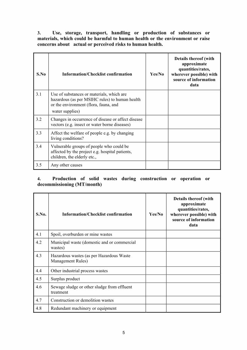
5
3. Use, storage, transport, handling or production of substances or
materials, which could be harmful to human health or the environment or raise
concerns about actual or perceived risks to human health.
S.No
Information/Checklist confirmation
Yes/No
Details thereof (with
approximate
quantities/rates,
wherever possible) with
source of information
data
3.1 Use of substances or materials, which are
hazardous (as per MSIHC rules) to human health
or the environment (flora, fauna, and
water supplies)
3.2 Changes in occurrence of disease or affect disease
vectors (e.g. insect or water borne diseases)
3.3 Affect the welfare of people e.g. by changing
living conditions?
3.4 Vulnerable groups of people who could be
affected by the project e.g. hospital patients,
children, the elderly etc.,
3.5 Any other causes
4. Production of solid wastes during construction or operation or
decommissioning (MT/month)
S.No.
Information/Checklist confirmation
Yes/No
Details thereof (with
approximate
quantities/rates,
wherever possible) with
source of information
data
4.1 Spoil, overburden or mine wastes
4.2 Municipal waste (domestic and or commercial
wastes)
4.3 Hazardous wastes (as per Hazardous Waste
Management Rules)
4.4 Other industrial process wastes
4.5 Surplus product
4.6 Sewage sludge or other sludge from effluent
treatment
4.7 Construction or demolition wastes
4.8 Redundant machinery or equipment

6
S.No.
Information/Checklist confirmation
Yes/No
Details thereof (with
approximate
quantities/rates,
wherever possible) with
source of information
data
4.9 Contaminated soils or other materials
4.10 Agricultural wastes
4.11 Other solid wastes
5. Release of pollutants or any hazardous, toxic or noxious substances to air
(kg/hr)
S.No
Information/Checklist confirmation
Yes/No
Details thereof (with
approximate
quantities/rates,
wherever possible) with
source of information
data
5.1 Emissions from combustion of fossil fuels from
stationary or mobile sources
5.2 Emissions from production processes
5.3 Emissions from materials handling including
storage or transport
5.4 Emissions from construction activities including
plant and equipment
5.5 Dust or odours from handling of materials
including construction materials, sewage and
waste
5.6 Emissions from incineration of waste
5.7 Emissions from burning of waste in open air (e.g.
slash materials, construction debris)
5.8 Emissions from any other sources

7
6. Generation of Noise and Vibration, and Emissions of Light and Heat:
S.No. Information/Checklist confirmation Yes/No Details thereof (with
approximate
quantities/rates, wherever
possible) with source of
information data with
source of information data
6.1 From operation of equipment e.g. engines,
ventilation plant, crushers
6.2 From industrial or similar processes
6.3 From construction or demolition
6.4 From blasting or piling
6.5 From construction or operational traffic
6.6 From lighting or cooling systems
6.7 From any other sources
7. Risks of contamination of land or water from releases of pollutants into
the ground or into sewers, surface waters, groundwater, coastal waters or the
sea:
S.No.
Information/Checklist confirmation
Yes/No
Details thereof (with
approximate
quantities/rates,
wherever possible) with
source of information
data
7.1 From handling, storage, use or spillage of
hazardous materials
7.2 From discharge of sewage or other effluents to
water or the land (expected mode and place of
discharge)
7.3 By deposition of pollutants emitted to air into
the land or into water
7.4 From any other sources
7.5 Is there a risk of long term build up of pollutants
in the environment from these sources?

8
8. Risk of accidents during construction or operation of the Project, which
could affect human health or the environment
S.No
Information/Checklist confirmation
Yes/No
Details thereof (with
approximate
quantities/rates, wherever
possible) with source of
information data
8.1 From explosions, spillages, fires etc from
storage, handling, use or production of hazardous
substances
8.2 From any other causes
8.3 Could the project be affected by natural disasters
causing environmental damage (e.g. floods,
earthquakes, landslides, cloudburst etc)?
9. Factors which should be considered (such as consequential development)
which could lead to environmental effects or the potential for cumulative impacts
with other existing or planned activities in the locality
S.
No.
Information/Checklist confirmation
Yes/No
Details thereof (with
approximate
quantities/rates, wherever
possible) with source of
information data
9.1 Lead to development of supporting facilities,
ancillary development or development
stimulated by the project which could have
impact on the environment e.g.:
Supporting infrastructure (roads, power
supply, waste or waste water treatment,
etc.)
housing development
extractive industries
supply industries
other
9.2 Lead to after-use of the site, which could have an
impact on the environment
9.3 Set a precedent for later developments
9.4 Have cumulative effects due to proximity to
other existing or planned projects with similar
effects

9
(III) ENVIRONMENTAL SENSITIVITY
S.No. Areas Name/
Identity
Aerial distance (within 15
km.)
Proposed project location
boundary
1 Areas protected under international conventions,
national or local legislation for their ecological,
landscape, cultural or other related value
2 Areas which are important or sensitive for
ecological reasons - Wetlands, watercourses or
other water bodies, coastal zone, biospheres,
mountains, forests
3 Areas used by protected, important or sensitive
species of flora or fauna for breeding, nesting,
foraging, resting, over wintering, migration
4 Inland, coastal, marine or underground waters
5 State, National boundaries
6 Routes or facilities used by the public for access
to recreation or other tourist, pilgrim areas
7 Defence installations
8 Densely populated or built-up area
9 Areas occupied by sensitive man-made land uses
(hospitals, schools, places of worship,
community facilities)
10 Areas containing important, high quality or
scarce resources (ground water resources,
surface resources, forestry, agriculture,
fisheries, tourism, minerals)
11 Areas already subjected to pollution or
environmental damage. (those where existing
legal environmental standards are exceeded)
12 Areas susceptible to natural hazard which could
cause the project to present environmental
problems (earthquakes, subsidence, landslides,
erosion, flooding or extreme or adverse climatic
conditions)

10
(IV) PROPOSED TERMS OF REFERENCE FOR EIA STUDIES
“I hereby given undertaking that the data and information given in the application and
enclosure are true to the best of my knowledge and belief and I am aware that if any
part of the data and information submitted is found to be false or misleading at any
stage, the project will be rejected and clearance give, if any to the project will be
revoked at our risk and cost.
Date:______________
Place:______________
Signature of the applicant
With Name and Full Address
(Project Proponent / Authorized Signatory)
NOTE:
1. The projects involving clearance under Coastal Regulation Zone
Notification, 1991 shall submit with the application a C.R.Z. map duly
demarcated by one of the authorized, agencies, showing the project
activities, w.r.t. C.R.Z. and the recommendations of the State Coastal Zone
Management Authority. Simultaneous action shall also be taken to obtain
the requisite clearance under the provisions of the C.R.Z. Notification,
1991 for the activities to be located in the CRZ.
2. The projects to be located within 10km of the National Parks, Sanctuaries,
Biosphere Reserves, Migratory Corridors of Wild Animals, the project
proponent shall submit the map duly authenticated by Chief Wildlife
Warden showing these features vis-à-vis the project location and the
recommendations or comments of the Chief Wildlife Warden thereon.”

ANNEXURE IX Pre-Feasibility Report: Points for Possible Coverage
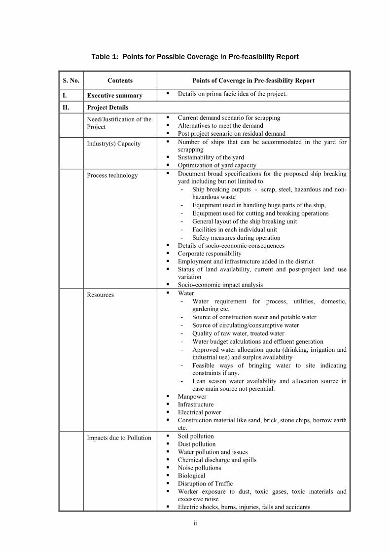
ii
Table 1: Points for Possible Coverage in Pre-feasibility Report
S. No. Contents Points of Coverage in Pre-feasibility Report
I. Executive summary Details on prima facie idea of the project.
II. Project Details
Need/Justification of the
Project
Current demand scenario for scrapping
Alternatives to meet the demand
Post project scenario on residual demand
Industry(s) Capacity
Number of ships that can be accommodated in the yard for
scrapping
Sustainability of the yard
Optimization of yard capacity
Process technology Document broad specifications for the proposed ship breaking
yard including but not limited to:
- Ship breaking outputs - scrap, steel, hazardous and non-
hazardous waste
- Equipment used in handling huge parts of the ship,
- Equipment used for cutting and breaking operations
- General layout of the ship breaking unit
- Facilities in each individual unit
- Safety measures during operation
Details of socio-economic consequences
Corporate responsibility
Employment and infrastructure added in the district
Status of land availability, current and post-project land use
variation
Socio-economic impact analysis
Resources Water
- Water requirement for process, utilities, domestic,
gardening etc.
- Source of construction water and potable water
- Source of circulating/consumptive water
- Quality of raw water, treated water
- Water budget calculations and effluent generation
- Approved water allocation quota (drinking, irrigation and
industrial use) and surplus availability
- Feasible ways of bringing water to site indicating
constraints if any.
- Lean season water availability and allocation source in
case main source not perennial.
Manpower
Infrastructure
Electrical power
Construction material like sand, brick, stone chips, borrow earth
etc.
Impacts due to Pollution Soil pollution
Dust pollution
Water pollution and issues
Chemical discharge and spills
Noise pollutions
Biological
Disruption of Traffic
Worker exposure to dust, toxic gases, toxic materials and
excessive noise
Electric shocks, burns, injuries, falls and accidents

iii
Fires and explosions
Induced secondary development puts increased demand on
infrastructure
Living standards of the workers/ Status/ Culture
Technical profile Construction details
- Estimated duration
- Number of construction workers including migrating
workers
- Construction equipment
- Vehicular traffic
- Source, mode of transportation and storage of construction
material
Traffic that would arise during different phases of the project
and transportation mechanism to handle such traffic
New facilities needed
Technical parameters of the yard & equipments to be used
Meteorological data like temp., humidity, rainfall, wind
pressure & wind direction Seismological studies of project
specific design seismic parameters
Project implementation schedule showing various activities
Environmental, health and safety measures
Project schedule
Outline project implementation and procurement arrangement
including contract packaging
Project implementation schedule showing various activities
Future prospects
Ascertain the costs and benefits of the proposed project for
project life
Technical and logistic constraints/ requirements of project
sustainability
III. Selection of site based on least possible impacts
i. Choice of site selection
Major techno-economic
feasibility considerations
Land availability & its development
General Layout
Access to site for transportation of equipments/construction
machinery, material, etc.
Fuel availability for transportation of waste and scrap
Water availability and consumptive use
Environmental and forest aspects
Ultimate yard capacity, which could be set up
Incompatible landuse
and ecologically
sensitive attributes with
respect to identified
suitable sites
If any incompatible land-use attributes fall within the study
area, the following details has to be provided:
- Public water supply areas from rivers/surface water
bodies, from groundwater
- Scenic areas/tourism areas/hill resorts
- Religious places, pilgrim centers that attract over 10 lakh
pilgrims a year
- Protected tribal settlements (notified tribal areas where
industrial activity is not permitted); CRZ
- Monuments of national significance, World Heritage Sites
- Cyclone, Tsunami prone areas (based on last 25 years);
- Airport areas
- Any other feature as specified by the State or local
government and other features as locally applicable,
including prime agricultural lands, pastures, migratory
corridors, etc.
If ecologically sensitive attributes fall within the study area,
please give details. Ecologically sensitive attributes include
- National parks
- Wild life sanctuaries Game reserve
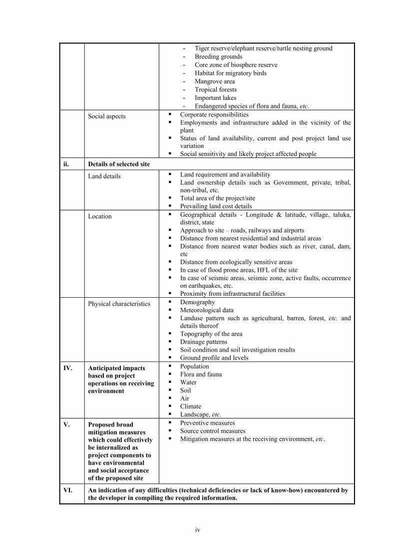
iv
- Tiger reserve/elephant reserve/turtle nesting ground
- Breeding grounds
- Core zone of biosphere reserve
- Habitat for migratory birds
- Mangrove area
- Tropical forests
- Important lakes
- Endangered species of flora and fauna, etc.
Social aspects Corporate responsibilities
Employments and infrastructure added in the vicinity of the
plant
Status of land availability, current and post project land use
variation
Social sensitivity and likely project affected people
ii. Details of selected site
Land details Land requirement and availability
Land ownership details such as Government, private, tribal,
non-tribal, etc.
Total area of the project/site
Prevailing land cost details
Location Geographical details - Longitude & latitude, village, taluka,
district, state
Approach to site – roads, railways and airports
Distance from nearest residential and industrial areas
Distance from nearest water bodies such as river, canal, dam,
etc
Distance from ecologically sensitive areas
In case of flood prone areas, HFL of the site
In case of seismic areas, seismic zone, active faults, occurrence
on earthquakes, etc.
Proximity from infrastructural facilities
Physical characteristics Demography
Meteorological data
Landuse pattern such as agricultural, barren, forest, etc. and
details thereof
Topography of the area
Drainage patterns
Soil condition and soil investigation results
Ground profile and levels
IV. Anticipated impacts
based on project
operations on receiving
environment
Population
Flora and fauna
Water
Soil
Air
Climate
Landscape, etc.
V. Proposed broad
mitigation measures
which could effectively
be internalized as
project components to
have environmental
and social acceptance
of the proposed site
Preventive measures
Source control measures
Mitigation measures at the receiving environment, etc.
VI. An indication of any difficulties (technical deficiencies or lack of know-how) encountered by
the developer in compiling the required information.

v
The above listing is not exhaustive. Thus the proponent may provide additional necessary
information, felt appropriate, to include in the pre-feasibility study report in support of selecting
the site for the proposed developmental activities. The EAC during scrutiny, may specifically ask
for any additional information/data required to substantiate the requirement to prescribe the ToR
for EIA studies. However, it is to make clear that all the required further information by EAC
may be mentioned in one single letter, within the prescribed time.

ANNEXURE X Types of Monitoring and Network Design Considerations
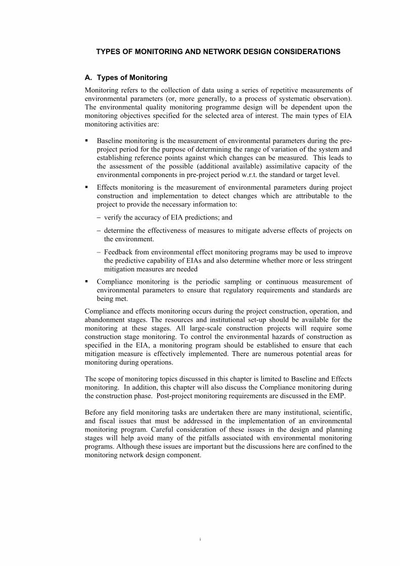
i
TYPES OF MONITORING AND NETWORK DESIGN CONSIDERATIONS
A. Types of Monitoring
Monitoring refers to the collection of data using a series of repetitive measurements of
environmental parameters (or, more generally, to a process of systematic observation).
The environmental quality monitoring programme design will be dependent upon the
monitoring objectives specified for the selected area of interest. The main types of EIA
monitoring activities are:
Baseline monitoring is the measurement of environmental parameters during the pre-
project period for the purpose of determining the range of variation of the system and
establishing reference points against which changes can be measured. This leads to
the assessment of the possible (additional available) assimilative capacity of the
environmental components in pre-project period w.r.t. the standard or target level.
Effects monitoring is the measurement of environmental parameters during project
construction and implementation to detect changes which are attributable to the
project to provide the necessary information to:
− verify the accuracy of EIA predictions; and
− determine the effectiveness of measures to mitigate adverse effects of projects on
the environment.
− Feedback from environmental effect monitoring programs may be used to improve
the predictive capability of EIAs and also determine whether more or less stringent
mitigation measures are needed
Compliance monitoring is the periodic sampling or continuous measurement of
environmental parameters to ensure that regulatory requirements and standards are
being met.
Compliance and effects monitoring occurs during the project construction, operation, and
abandonment stages. The resources and institutional set-up should be available for the
monitoring at these stages. All large-scale construction projects will require some
construction stage monitoring. To control the environmental hazards of construction as
specified in the EIA, a monitoring program should be established to ensure that each
mitigation measure is effectively implemented. There are numerous potential areas for
monitoring during operations.
The scope of monitoring topics discussed in this chapter is limited to Baseline and Effects
monitoring. In addition, this chapter will also discuss the Compliance monitoring during
the construction phase. Post-project monitoring requirements are discussed in the EMP.
Before any field monitoring tasks are undertaken there are many institutional, scientific,
and fiscal issues that must be addressed in the implementation of an environmental
monitoring program. Careful consideration of these issues in the design and planning
stages will help avoid many of the pitfalls associated with environmental monitoring
programs. Although these issues are important but the discussions here are confined to the
monitoring network design component.
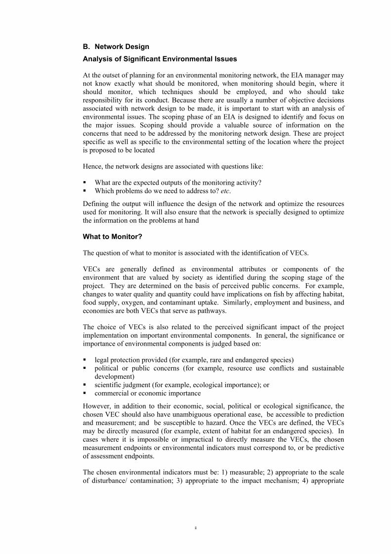
ii
B. Network Design
Analysis of Significant Environmental Issues
At the outset of planning for an environmental monitoring network, the EIA manager may
not know exactly what should be monitored, when monitoring should begin, where it
should monitor, which techniques should be employed, and who should take
responsibility for its conduct. Because there are usually a number of objective decisions
associated with network design to be made, it is important to start with an analysis of
environmental issues. The scoping phase of an EIA is designed to identify and focus on
the major issues. Scoping should provide a valuable source of information on the
concerns that need to be addressed by the monitoring network design. These are project
specific as well as specific to the environmental setting of the location where the project
is proposed to be located
Hence, the network designs are associated with questions like:
What are the expected outputs of the monitoring activity?
Which problems do we need to address to? etc.
Defining the output will influence the design of the network and optimize the resources
used for monitoring. It will also ensure that the network is specially designed to optimize
the information on the problems at hand
What to Monitor?
The question of what to monitor is associated with the identification of VECs.
VECs are generally defined as environmental attributes or components of the
environment that are valued by society as identified during the scoping stage of the
project. They are determined on the basis of perceived public concerns. For example,
changes to water quality and quantity could have implications on fish by affecting habitat,
food supply, oxygen, and contaminant uptake. Similarly, employment and business, and
economies are both VECs that serve as pathways.
The choice of VECs is also related to the perceived significant impact of the project
implementation on important environmental components. In general, the significance or
importance of environmental components is judged based on:
legal protection provided (for example, rare and endangered species)
political or public concerns (for example, resource use conflicts and sustainable
development)
scientific judgment (for example, ecological importance); or
commercial or economic importance
However, in addition to their economic, social, political or ecological significance, the
chosen VEC should also have unambiguous operational ease, be accessible to prediction
and measurement; and be susceptible to hazard. Once the VECs are defined, the VECs
may be directly measured (for example, extent of habitat for an endangered species). In
cases where it is impossible or impractical to directly measure the VECs, the chosen
measurement endpoints or environmental indicators must correspond to, or be predictive
of assessment endpoints.
The chosen environmental indicators must be: 1) measurable; 2) appropriate to the scale
of disturbance/ contamination; 3) appropriate to the impact mechanism; 4) appropriate

iii
and proportional to temporal dynamics; 5) diagnostic; and 6) standardized; as well as
have: 1) a low natural variability; 2) a broad applicability; and 3) an existing data series.
Where, How and How Many Times to Monitor?
These are the other components of Monitoring Network Design. These questions are best
answered based on local field conditions, capacity and resources available, prevailing
legal and regulatory priorities, etc. For this, screening or reconnaissance surveys of the
study area are also necessary. This may also include some simple inexpensive
measurements and assimilative/dispersion modeling. The data will give some information
on the prevailing special and temporal variations, and the general background air
pollution in the area. The number of monitoring stations and the indicators to be
measured at each station in the final permanent network may then be decided upon based
on the results of the screening study as well as on the knowledge of the sources of the
proposed development and prevailing local environmental/meteorological conditions. The
best possible definition of the air pollution problem, together with the analysis of the
resources: personnel, budget and equipment available, represent the basis for the decision
on the following questions:
What spatial density (number) of sampling stations is required? How many samples
are needed and during what period (sampling (averaging) time and frequency)?
Where should the stations be located?
What kind of equipment should be used?
What additional background information is needed?
− meteorology
− topography
− population density
− emission sources and emission rates
− effects and impacts
How will the data be made available/communicated?
C. Site Selection
When considering the location of individual samplers, it is essential that the data collected
are representative for the location and type of area without the undue influence from the
immediate surroundings. In any measurement point in the study area the total ambient
concentration is the representative of:
natural background concentration
regional background
impact of existing large regional sources such as Industrial emissions
To obtain the information about the importance of these different contributions it is
therefore necessary to locate monitoring stations so that they are representative for
different impacts. In addition to the ambient pollution data, one would often need other
data governing the variations such as meteorological data for air pollution, to identify and
quantify the sources contributing to the measurements.

ANNEXURE XI Guidance for Assessment of Baseline Components and Attributes
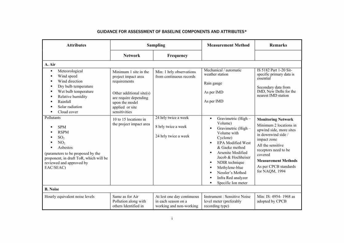
i
GUIDANCE FOR ASSESSMENT OF BASELINE COMPONENTS AND ATTRIBUTES*
Sampling Remarks Attributes
Network Frequency
Measurement Method
A. Air
Meteorological
Wind speed
Wind direction
Dry bulb temperature
Wet bulb temperature
Relative humidity
Rainfall
Solar radiation
Cloud cover
Minimum 1 site in the
project impact area
requirements
Other additional site(s)
are require depending
upon the model
applied or site
sensitivities
Min: 1 hrly observations
from continuous records
Mechanical / automatic weather station
Rain gauge
As per IMD
As per IMD
IS 5182 Part 1-20 Sit-specific primary data is essential
Secondary data from IMD, New Delhi for the nearest IMD station
Pollutants
SPM
RSPM
SO2
NO2
Asbestos
(parameters to be proposed by the
proponent, in draft ToR, which will be
reviewed and approved by
EAC/SEAC)
10 to 15 locations in
the project impact area
24 hrly twice a week
8 hrly twice a week
24 hrly twice a week
Gravimetric (High –
Volume)
Gravimetric (High –
Volume with
Cyclone)
EPA Modified West
& Gaeke method
Arsenite Modified
Jacob & Hochheiser
NDIR technique
Methylene-blue
Nessler’s Method
Infra Red analyzer
Specific Ion meter
Monitoring Network
Minimum 2 locations in
upwind side, more sites
in downwind side /
impact zone
All the sensitive
receptors need to be
covered
Measurement Methods
As per CPCB standards
for NAQM, 1994
B. Noise
Hourly equivalent noise levels Same as for Air
Pollution along with
others Identified in
At lest one day continuous
in each season on a
working and non-working
Instrument : Sensitive Noise
level meter (preferably
recording type)
Min: IS: 4954- 1968 as
adopted by CPCB

ii
Sampling Remarks Attributes
Network Frequency
Measurement Method
study area day
Hourly equivalent noise levels Inplant (1.5 m from
machinery or high
emission processes)
Same as above for day and
night
Instrument : Noise level
meter
CPCB / OSHA
Hourly equivalent noise levels Highways (within 500
metres from the road
edge)
Same as above for day and
night
Instrument : Noise level
meter
CPCB / IS : 4954-1968
Peak particle velocity 150- 200m from blast
site
Based on hourly
observations
PPV meter
C. Land Environment
Soil
Particle size distribution
Texture
pH
Electrical conductivity
Caution exchange capacity
Alkali metals
Sodium Absorption Ratio
(SAR)
Permeability
Porosity
One surface sample
from each landfill
and/or hazardous waste
site (if applicable) and
prime villages, (soil
samples be collected as
per BIS specifications)
in the study area
Season-wise Collected and analyzed as
per soil analysis reference
book, M.I.Jackson and soil
analysis reference book by
C.A. Black
The purpose of impact
assessment on soil (land
environment) is to assess
the significant impacts
due to leaching of wastes
or accidental releases and
contaminating
Land Use/Landscape
Location code
Total project area
Topography
Drainage (natural)
Cultivated, forest plantations,
water bodies, roads and
At least 20 points
along with plant
boundary and general
major land use
categories in the study
area. `
Drainage once in the study
period and land use
categories from secondary
data (local maps) and
satellite imageries
Global positioning
system
Topo-sheets
Satellite Imageries
(1:25,000)
Drainage within the plant
area and surrounding is
very important for storm
water impacts.
From land use maps
sensitive receptors
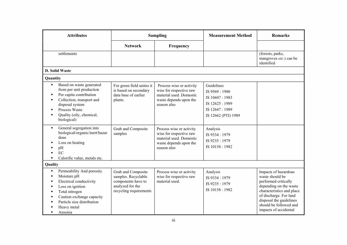
iii
Sampling Remarks Attributes
Network Frequency
Measurement Method
settlements (forests, parks,
mangroves etc.) can be
identified
D. Solid Waste
Quantity
Based on waste generated
from per unit production
Per capita contribution
Collection, transport and
disposal system
Process Waste
Quality (oily, chemical,
biological)
For green field unites it
is based on secondary
data base of earlier
plants.
Process wise or activity
wise for respective raw
material used. Domestic
waste depends upon the
season also
Guidelines
IS 9569 : 1980
IS 10447 : 1983
IS 12625 : 1989
IS 12647 : 1989
IS 12662 (PTI) 1989
General segregation into
biological/organic/inert/hazar
dous
Loss on heating
pH
EC
Calorific value, metals etc.
Grab and Composite
samples
Process wise or activity
wise for respective raw
material used. Domestic
waste depends upon the
season also
Analysis
IS 9334 : 1979
IS 9235 : 1979
IS 10158 : 1982
Quality
Permeability And porosity
Moisture pH
Electrical conductivity
Loss on ignition
Total nitrogen
Caution exchange capacity
Particle size distribution
Heavy metal
Ansonia
Grab and Composite
samples. Recyclable
components have to
analyzed for the
recycling requirements
Process wise or activity
wise for respective raw
material used.
Analysis
IS 9334 : 1979
IS 9235 : 1979
IS 10158 : 1982
Impacts of hazardous
waste should be
performed critically
depending on the waste
characteristics and place
of discharge. For land
disposal the guidelines
should be followed and
impacts of accidental

iv
Sampling Remarks Attributes
Network Frequency
Measurement Method
releases should be
assessed
C. Water
Parameters for water quality
pH, temp, turbidity,
magnesium hardness, total
alkalinity, chloride, sulphate,
nitrate, fluoride, sodium,
potassium , salinity
Total nitrogen, total
phosphorus, DO, BOD, COD,
Phenol
Heavy metals
Total coliforms, faecal
coliforms
Phyto plankton
Zooplankton
Fish & other aquatic flora &
fauna
(relevant parameters are to be
given in points of coverage
for EIA studies based on
nature of project and
anticipated impacts)
Set of grab samples
during pre and post-
monsoon for ground
and surface water for
the whole study zone.
For laboratory
analysis, the samples
should be preserved
appropriately
Diurnal and season-wise Samples for water quality
should be collected and
analyzed as per:
IS: 2488 (Part 1-5) methods
for sampling and testing of
industrial effluents
Standard methods for
examination of water and
waste water analysis
published by American
Public Health Association.
International standard
practices for benthos and
aquatic flora & fauna
For Surface Water bodies
Total Carbon
PH
Dissolved Oxygen
Biological Oxygen
Demand
Ammonia
Monitoring locations
should include up-
stream, on site, down
stream of proposed
discharge point.
Besides sampling
Yield & impact on water
sources to be measured
during critical season
River Stretch within
project area be divided in
grids (say 1 km length and
Samples for water quality
should be collected and
analyzed as per:
IS: 2488 (Part 1-5) methods
for sampling and testing of
industrial effluents
Historical data should be
collected from relevant
offices such as central
water commission, state
and central ground water
board, Irrigation dept.

v
Sampling Remarks Attributes
Network Frequency
Measurement Method
Boron
Sodium Absorption ratio
Electrical Conductivity etc.
should cover width of
the river in case water
quality modeling is
proposed.
Standard methodology
for collection of
surface water (BIS
standards)
At least one grab
sample per location per
season
1/3 width) and samples
should be from each grid
at a time when the
wastewater discharged by
other sources of pollution
is expected to be
maximum
Standard methods for
examination of water and
wastewater analysis
published by American
Public Health Association.
Parameters for Wastewater Characterization
Temp, colour, odour,
turbidity, TSS, TDS, pH ,
alkalinity as CaCO3, p value,
M value, tatal hardness as
CaCO3, chloride as cl,
sulphate as S04, Nitrate as
NO3, Floride as F, Phosphate
as P04, Chromium as Cr
(Hexavalent, total)
Ammonical Nitrogen as N,
TKN, % sodium, BOD at 20
C, COD, DO, total residual
chlorine as Cl2, oil and
grease, sulphide, phenolic
compound
Implant Source
depending upon the
different waste streams
the parameters can be
optimized
Grab and composite
sampling representing
avg of different
process operations as
well as worst emission
scenario should be
represented
Different operational
cycles as well as raw
material variations should
be reflected in the analysis
Samples for water quality
should be collected and
analyzed as per:
IS: 2488 (Part 1-5) methods
for sampling and testing of
industrial effluents
Standard methods for
examination of water and
wastewater analysis
published by American
Public Health Association.
All plant sources
categorized as:
Different Process
waste streams as
well as run-off
conditions
ETP wastewater
Domestic/
sanitary
wastewater
E. Biological Environment
Aquatic
Primary productivity
Aquatic weeds
Considering probable
impact, sampling
points and number of
samples to be decided
Season changes are very
important
Standards techniques (APHA
et. Al. 1995, Rau and
Wooten 1980) to be followed
for sampling and
Seasonal sampling for
aquatic biota
One season for terrestrial

vi
Sampling Remarks Attributes
Network Frequency
Measurement Method
Enumeration of
phytoplankton, zooplankton
and benthos
Fisheries
Diversity indices
Trophic levels
Rare and endangered species
Sanctuaries / closed areas /
Coastal regulation zone
(CRZ)
Terrestrial
Vegetation – species, list,
economic importance, forest
produce, medicinal value
Importance value index (IVI)
of trees
Wild animals
on established
guidelines on
ecological studies
based on site eco-
environment setting
within 10/25 km radius
from the proposed site
Samples to collect
from upstream and
downstream of
discharge point, nearby
tributaries at down
stream, and also from
dug wells close to
activity site
measurement biota, in addition to
vegetation studies during
monsoon season
Preliminary assessment
Microscopic analysis of
plankton and
meiobenthos, studies of
macrofauna, aquatic
vegetation and
application of indices,
viz. Shannon, similarity,
dominance IVI, etc
Point quarter plot-less
method (random
sampling) for terrestrial
vegetation survey.
Avifauna
Rare and endangered species
Sanctuaries / National park /
Biosphere reserve
For forest studies,
chronic as well as
short-term impacts
should be analyzed
warranting data on
micro climate
conditions
Secondary data to collect
from Government
offices, NGOs, published
literature
Plankton net
Sediment dredge
Depth sampler
Microscope
Field binocular
F. Socio-economic

vii
Sampling Remarks Attributes
Network Frequency
Measurement Method
Demographic structure
Infrastructure resource base
Economic resource base
Health status: Morbidity
pattern
Cultural and aesthetic
attributes
Socio-economic
survey is based on
proportionate,
stratified and random
sampling method
Different impacts occurs
during construction and
operational phases of the
project
Primary data collection
through R&R surveys (if
require) or community
survey are based on personal
interviews and questionnaire
Secondary data from
census records, statistical
hard books, toposheets,
health records and
relevant official records
available with Govt.
agencies
* Project Specific concerned parameters needs to be identified by the project proponent and shall be incorporated in the draft ToR, to be submitted to the Authority for the
consideration and approval by the EAC/SEAC.

ANNEXURE XII
Sources of Secondary Data
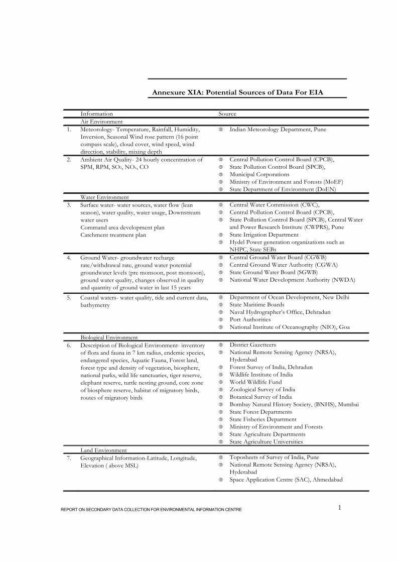
Annexure XIA: Potential Sources of Data For EIA
Information
Air Environment
1. Meteorology- Temperature, Rainfall, Humidity,
Inversion, Seasonal Wind rose pattern (16 point
compass scale), cloud cover, wind speed, wind
direction, stability, mixing depth
2. Ambient Air Quality- 24 hourly concentration of
SPM, RPM, SO2, NOx, CO
Water Environment
3. Surface water- water sources, water flow (lean
season), water quality, water usage, Downstream
water users
Command area development plan
Catchment treatment plan
4. Ground Water- groundwater recharge
rate/withdrawal rate, ground water potential
groundwater levels (pre monsoon, post monsoon),
ground water quality, changes observed in quality
and quantity of ground water in last 15 years
5. Coastal waters- water quality, tide and current data,
bathymetry
Biological Environment
6. Description of Biological Environment- inventory
of flora and fauna in 7 km radius, endemic species,
endangered species, Aquatic Fauna, Forest land,
forest type and density of vegetation, biosphere,
national parks, wild life sanctuaries, tiger reserve,
elephant reserve, turtle nesting ground, core zone
of biosphere reserve, habitat of migratory birds,
routes of migratory birds
Land Environment
7. Geographical Information-Latitude, Longitude,
Elevation ( above MSL)
Source
¤ Indian Meteorology Department, Pune
¤ Central Pollution Control Board (CPCB),
¤ State Pollution Control Board (SPCB),
¤ Municipal Corporations
¤ Ministry of Environment and Forests (MoEF)
¤ State Department of Environment (DoEN)
¤ Central Water Commission (CWC),
¤ Central Pollution Control Board (CPCB),
¤ State Pollution Control Board (SPCB), Central Water
and Power Research Institute (CWPRS), Pune
¤ State Irrigation Department
¤ Hydel Power generation organizations such as NHPC, State SEBs
¤ Central Ground Water Board (CGWB)
¤ Central Ground Water Authority (CGWA)
¤ State Ground Water Board (SGWB)
¤ National Water Development Authority (NWDA)
¤ Department of Ocean Development, New Delhi ¤ State Maritime Boards
¤ Naval Hydrographer’s Office, Dehradun
¤ Port Authorities
¤ National Institute of Oceanography (NIO), Goa
¤ District Gazetteers
¤ National Remote Sensing Agency (NRSA), Hyderabad
¤ Forest Survey of India, Dehradun
¤ Wildlife Institute of India
¤ World Wildlife Fund
¤ Zoological Survey of India
¤ Botanical Survey of India
¤ Bombay Natural History Society, (BNHS), Mumbai
¤ State Forest Departments
¤ State Fisheries Department
¤ Ministry of Environment and Forests
¤ State Agriculture Departments
¤ State Agriculture Universities
¤ Toposheets of Survey of India, Pune
¤ National Remote Sensing Agency (NRSA), Hyderabad
¤ Space Application Centre (SAC), Ahmedabad
REPORT ON SECONDARY DATA COLLECTION FOR ENVIRONMENTAL INFORMATION CENTRE 1
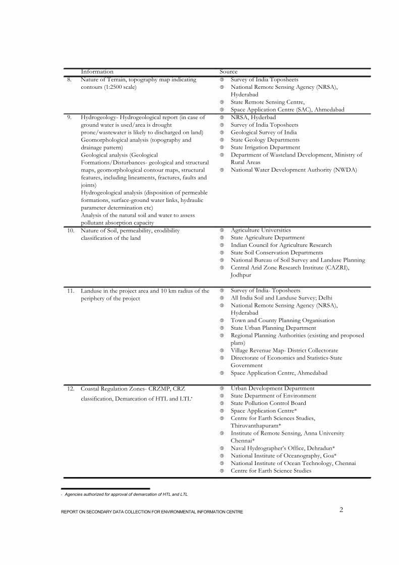
Information
8. Nature of Terrain, topography map indicating
contours (1:2500 scale)
9. Hydrogeology- Hydrogeological report (in case of
ground water is used/area is drought
prone/wastewater is likely to discharged on land)
Geomorphological analysis (topography and
drainage pattern)
Geological analysis (Geological
Formations/Disturbances- geological and structural
maps, geomorphological contour maps, structural
features, including lineaments, fractures, faults and
joints)
Hydrogeological analysis (disposition of permeable
formations, surface-ground water links, hydraulic
parameter determination etc)
Analysis of the natural soil and water to assess
pollutant absorption capacity
10. Nature of Soil, permeability, erodibility
classification of the land
11. Landuse in the project area and 10 km radius of the
periphery of the project
12. Coastal Regulation Zones- CRZMP, CRZ
classification, Demarcation of HTL and LTL෪
෪ Agencies authorized for approval of demarcation of HTL and LTL
Source
¤ Survey of India Toposheets
¤ National Remote Sensing Agency (NRSA),
Hyderabad
¤ State Remote Sensing Centre,
¤ Space Application Centre (SAC), Ahmedabad
¤ NRSA, Hyderbad
¤ Survey of India Toposheets
¤ Geological Survey of India
¤ State Geology Departments
¤ State Irrigation Department
¤ Department of Wasteland Development, Ministry of Rural Areas
¤ National Water Development Authority (NWDA)
¤ Agriculture Universities
¤ State Agriculture Department
¤ Indian Council for Agriculture Research
¤ State Soil Conservation Departments
¤ National Bureau of Soil Survey and Landuse Planning
¤ Central Arid Zone Research Institute (CAZRI), Jodhpur
¤ Survey of India- Toposheets
¤ All India Soil and Landuse Survey; Delhi
¤ National Remote Sensing Agency (NRSA),
Hyderabad
¤ Town and County Planning Organisation
¤ State Urban Planning Department
¤ Regional Planning Authorities (existing and proposed
plans)
¤ Village Revenue Map- District Collectorate
¤ Directorate of Economics and Statistics-State
Government
¤ Space Application Centre, Ahmedabad
¤ Urban Development Department
¤ State Department of Environment
¤ State Pollution Control Board
¤ Space Application Centre*
¤ Centre for Earth Sciences Studies, Thiruvanthapuram*
¤ Institute of Remote Sensing, Anna University
Chennai*
¤ Naval Hydrographer’s Office, Dehradun*
¤ National Institute of Oceanography, Goa*
¤ National Institute of Ocean Technology, Chennai
¤ Centre for Earth Science Studies
REPORT ON SECONDARY DATA COLLECTION FOR ENVIRONMENTAL INFORMATION CENTRE 2

Information
Social
13. Socioeconomic - population, number of houses
and present occupation pattern within 7 km from
the periphery of the project
14. Monuments and heritage sites
Natural Disasters
15. Seismic data (Mining Projects)- zone no, no of
earthquakes and scale, impacts on life, property
existing mines
16. Landslide prone zone, geomorphological
conditions, degree of susceptibility to mass
movement, major landslide history (frequency of
occurrence/decade), area affected, population
affected
17. Flood/cyclone/droughts- frequency of occurrence
per decade, area affected, population affected
Industrial
18. Industrial Estates/Clusters, Growth Centres
19. Physical and Chemical properties of raw material
and chemicals (Industrial projects); fuel quality
20. Occupational Health and Industrial Hygiene-
major occupational health and safety hazards,
health and safety requirements, accident histories
21. Pollutant release inventories (Existing pollution
sources in area within 10 km radius)
22. Water requirement (process, cooling water, DM
water, Dust suppression, drinking, green belt, fire
service)
Source
¤ Census Department
¤ District Gazetteers- State Government
¤ District Statistics- District Collectorate
¤ International Institute of Population Sciences,
Mumbai (limited data)
¤ Central Statistical Organisation
District Gazetteer
Archeological Survey of India,
INTACH
District Collectorate
Central and State Tourism Department
State Tribal and Social Welfare Department
¤ Indian Meteorology Department, Pune
¤ Geological Survey of India
¤ Space Application Centre
¤ Natural Disaster Management Division in Department of Agriculture and Cooperation
¤ Indian Meteorological Department
¤ State Industrial Corporation
¤ Industrial Associations
¤ State Pollution Control Boards ¤ Confederation Indian Industries (CII)
¤ FICCI
¤ Material and Safety Data Sheets ¤ ENVIS database of Industrial Toxicological Research
Centre, Lucknow
¤ Indian Institute Petroleum
¤ Central Labour Institute, Mumbai
¤ Directorate of Industrial Safety
¤ ENVIS Database of Industrial Toxicological Research
Centre, Lucknow
¤ National Institute of Occupational Health,
Ahmedabad
¤ Project proponents which have received EC and have commenced operations
¤ EIA Reports
¤ National and International Benchmarks
REPORT ON SECONDARY DATA COLLECTION FOR ENVIRONMENTAL INFORMATION CENTRE 3

Annexure XIB: Summary of Available Data with Potential Data Sources for EIA
Agency
1. Archaeological Survey of India
Department of Culture
Government of India
Janpath, New Delhi - 110011
2. Botanical Survey Of India
P-8, Brabourne Road Calcutta
700001
Tel#033 2424922
Fax#033 2429330
Email: [email protected]. .
RO - Coimbatore, Pune, Jodhpur,
Dehradun, Allahabad, Gantok,
Itanagar, Port Blair
3. Bureau of Indian Standards
Manak Bhawan, 9 Bahadur Shah
Zafar Marg, New Delhi 110 002
Tel#3230131, 3233375, 3239402 (10
lines)
Fax : 91 11 3234062, 3239399,
3239382
Email- [email protected]
4. Central Water Commission (CWC)
Sewa Bhawan, R.K.Puram
New Delhi - 110066
RO- Bangalore, Bhopal,
Bhubaneshwar, Chandigarh,
Coimbatore/Chennai, Delhi,
Hyderabad, Lucknow, Nagpur,
Patna, Shillong, Siliguri and
Vadodara
5. Central Ground Water Board
(HO) N.H.IV, New CGO
Complex,
Faridabad - 121001
RO - Guwahati, Chandigarh,
Ahemadabad, Trivandrum,
Calcutta, Bhopal, Lucknow,
Banglore, Nagpur, Jammu,
Bhubneshwar, Raipur, Jaipur,
Chennai, Hyderabad, Patna
16 Based on web search and literature review
Information Available
¤ Inventory of monuments and sites of national importance- Listing and
documentation of monuments according to world heritage, pre
historic, proto historic and secular, religious places and forts
¤ Photodiversity documentation of flora at National, State and District level and flora of protected areas, hotspots, fragile ecosystems, sacred
groves etc
¤ Identification of threatened species including endemics, their
mapping, population studies
¤ Database related to medicinal plants, rare and threatened plant species
¤ Red data book of Indian plants (Vol 1,2, and 3)
¤ Manual for roadside and avenue plantation in India
¤ Bureau of Indian Standards Committees on Earthquake Engineering and Wind Engineering have a Seismic Zoning Map and the Wind
Velocity Map including cyclonic winds for the country
¤ Central Data Bank -Collection, collation and Publishing of Hydrological, Hydrometeorological, Sediment and Water Quality
data-.
¤ Basin wise Master Plans
¤ Flood atlas for India
¤ Flood Management and Development and Operation of Flood
Forecasting System- CWC operate a network of forecasting stations
Over 6000 forecasts are issued every year with about 95% of the
forecasts within the permissible limit.
¤ Water Year Books, Sediment Year Books and Water Quality Year
Books.
¤ Also actively involved in monitoring of 84 identified projects through National, State and Project level Environmental Committees for
ensuring implementation of environmental safeguards
¤ surveys, exploration, monitoring of ground water development
REPORT ON SECONDARY DATA COLLECTION FOR ENVIRONMENTAL INFORMATION CENTRE 4
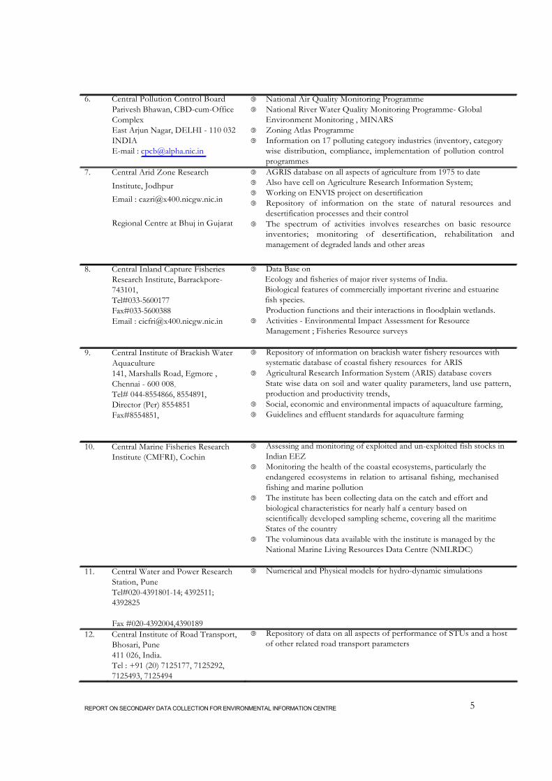
6. Central Pollution Control Board
Parivesh Bhawan, CBD-cum-Office
Complex
East Arjun Nagar, DELHI - 110 032
INDIA
E-mail : [email protected]
7. Central Arid Zone Research
Institute, Jodhpur
Email : [email protected]
Regional Centre at Bhuj in Gujarat
8. Central Inland Capture Fisheries
Research Institute, Barrackpore-
743101,
Tel#033-5600177
Fax#033-5600388
Email : [email protected]
9. Central Institute of Brackish Water
Aquaculture
141, Marshalls Road, Egmore ,
Chennai - 600 008,
Tel# 044-8554866, 8554891,
Director (Per) 8554851
Fax#8554851,
10. Central Marine Fisheries Research
Institute (CMFRI), Cochin
11. Central Water and Power Research
Station, Pune
Tel#020-4391801-14; 4392511;
4392825
Fax #020-4392004,4390189
12. Central Institute of Road Transport,
Bhosari, Pune
411 026, India.
Tel : +91 (20) 7125177, 7125292,
7125493, 7125494
¤ National Air Quality Monitoring Programme
¤ National River Water Quality Monitoring Programme- Global
Environment Monitoring , MINARS
¤ Zoning Atlas Programme
¤ Information on 17 polluting category industries (inventory, category
wise distribution, compliance, implementation of pollution control
programmes
¤ AGRIS database on all aspects of agriculture from 1975 to date
¤ Also have cell on Agriculture Research Information System;
¤ Working on ENVIS project on desertification
¤ Repository of information on the state of natural resources and
desertification processes and their control
¤ The spectrum of activities involves researches on basic resource inventories; monitoring of desertification, rehabilitation and
management of degraded lands and other areas
¤ Data Base on
Ecology and fisheries of major river systems of India. Biological features of commercially important riverine and estuarine
fish species.
Production functions and their interactions in floodplain wetlands.
¤ Activities - Environmental Impact Assessment for Resource Management ; Fisheries Resource surveys
¤ Repository of information on brackish water fishery resources with systematic database of coastal fishery resources for ARIS
¤ Agricultural Research Information System (ARIS) database covers
State wise data on soil and water quality parameters, land use pattern, production and productivity trends,
¤ Social, economic and environmental impacts of aquaculture farming,
¤ Guidelines and effluent standards for aquaculture farming
¤ Assessing and monitoring of exploited and un-exploited fish stocks in
Indian EEZ
¤ Monitoring the health of the coastal ecosystems, particularly the
endangered ecosystems in relation to artisanal fishing, mechanised
fishing and marine pollution
¤ The institute has been collecting data on the catch and effort and
biological characteristics for nearly half a century based on scientifically developed sampling scheme, covering all the maritime
States of the country
¤ The voluminous data available with the institute is managed by the
National Marine Living Resources Data Centre (NMLRDC)
¤ Numerical and Physical models for hydro-dynamic simulations
¤ Repository of data on all aspects of performance of STUs and a host
of other related road transport parameters
REPORT ON SECONDARY DATA COLLECTION FOR ENVIRONMENTAL INFORMATION CENTRE 5
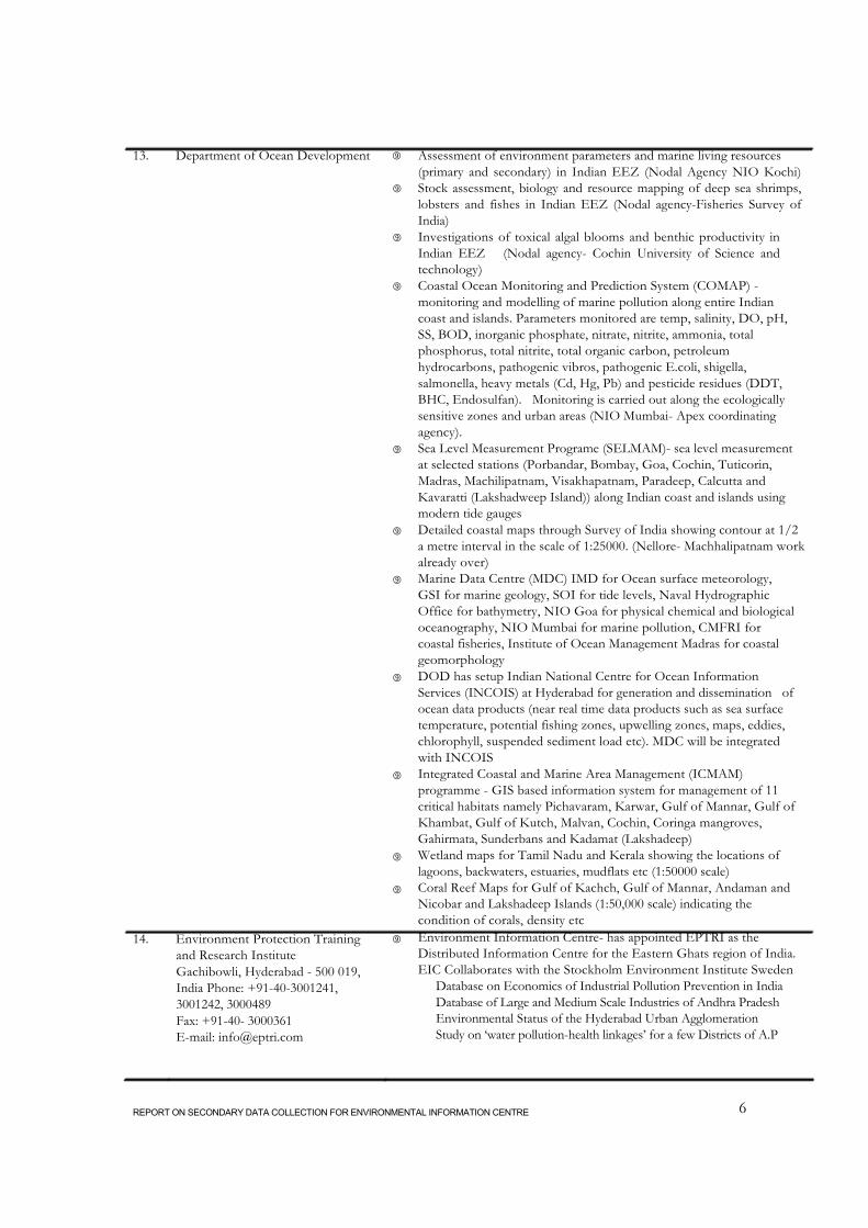
13. Department of Ocean Development ¤
¤ ¤ ¤
¤
¤
¤ ¤ ¤
¤
¤
14. Environment Protection Training ¤
and Research Institute
Gachibowli, Hyderabad - 500 019,
India Phone: +91-40-3001241,
3001242, 3000489
Fax: +91-40- 3000361
E-mail: [email protected]
Assessment of environment parameters and marine living resources
(primary and secondary) in Indian EEZ (Nodal Agency NIO Kochi)
Stock assessment, biology and resource mapping of deep sea shrimps,
lobsters and fishes in Indian EEZ (Nodal agency-Fisheries Survey of
India)
Investigations of toxical algal blooms and benthic productivity in
Indian EEZ (Nodal agency- Cochin University of Science and technology)
Coastal Ocean Monitoring and Prediction System (COMAP) -
monitoring and modelling of marine pollution along entire Indian
coast and islands. Parameters monitored are temp, salinity, DO, pH,
SS, BOD, inorganic phosphate, nitrate, nitrite, ammonia, total
phosphorus, total nitrite, total organic carbon, petroleum
hydrocarbons, pathogenic vibros, pathogenic E.coli, shigella,
salmonella, heavy metals (Cd, Hg, Pb) and pesticide residues (DDT,
BHC, Endosulfan). Monitoring is carried out along the ecologically
sensitive zones and urban areas (NIO Mumbai- Apex coordinating
agency).
Sea Level Measurement Programe (SELMAM)- sea level measurement
at selected stations (Porbandar, Bombay, Goa, Cochin, Tuticorin,
Madras, Machilipatnam, Visakhapatnam, Paradeep, Calcutta and
Kavaratti (Lakshadweep Island)) along Indian coast and islands using
modern tide gauges
Detailed coastal maps through Survey of India showing contour at 1/2
a metre interval in the scale of 1:25000. (Nellore- Machhalipatnam work
already over)
Marine Data Centre (MDC) IMD for Ocean surface meteorology,
GSI for marine geology, SOI for tide levels, Naval Hydrographic
Office for bathymetry, NIO Goa for physical chemical and biological
oceanography, NIO Mumbai for marine pollution, CMFRI for
coastal fisheries, Institute of Ocean Management Madras for coastal
geomorphology
DOD has setup Indian National Centre for Ocean Information
Services (INCOIS) at Hyderabad for generation and dissemination of
ocean data products (near real time data products such as sea surface
temperature, potential fishing zones, upwelling zones, maps, eddies,
chlorophyll, suspended sediment load etc). MDC will be integrated
with INCOIS
Integrated Coastal and Marine Area Management (ICMAM)
programme - GIS based information system for management of 11
critical habitats namely Pichavaram, Karwar, Gulf of Mannar, Gulf of
Khambat, Gulf of Kutch, Malvan, Cochin, Coringa mangroves,
Gahirmata, Sunderbans and Kadamat (Lakshadeep)
Wetland maps for Tamil Nadu and Kerala showing the locations of
lagoons, backwaters, estuaries, mudflats etc (1:50000 scale)
Coral Reef Maps for Gulf of Kachch, Gulf of Mannar, Andaman and Nicobar and Lakshadeep Islands (1:50,000 scale) indicating the
condition of corals, density etc
Environment Information Centre- has appointed EPTRI as the Distributed Information Centre for the Eastern Ghats region of India.
EIC Collaborates with the Stockholm Environment Institute Sweden
Database on Economics of Industrial Pollution Prevention in India
Database of Large and Medium Scale Industries of Andhra Pradesh Environmental Status of the Hyderabad Urban Agglomeration
Study on ‘water pollution-health linkages’ for a few Districts of A.P
REPORT ON SECONDARY DATA COLLECTION FOR ENVIRONMENTAL INFORMATION CENTRE 6
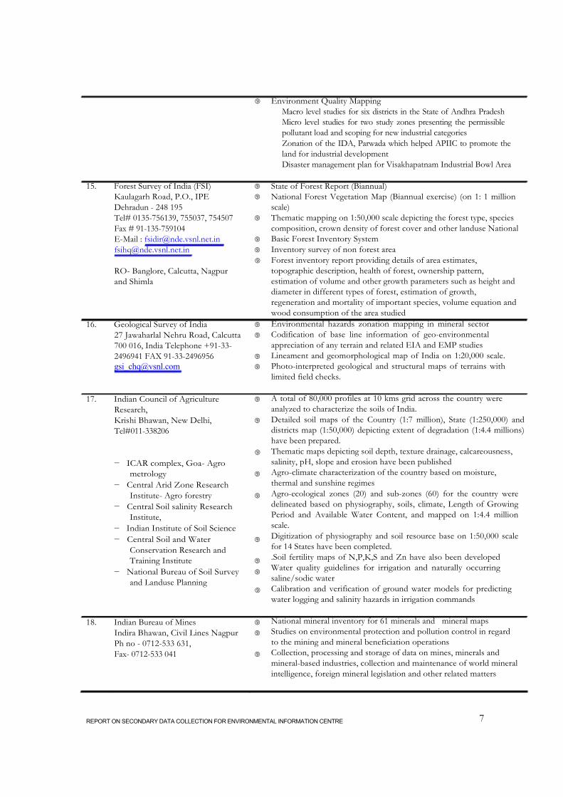
¤
15. Forest Survey of India (FSI) ¤
Kaulagarh Road, P.O., IPE ¤
Dehradun - 248 195
Tel# 0135-756139, 755037, 754507 ¤
Fax # 91-135-759104
E-Mail : [email protected] ¤
¤
RO- Banglore, Calcutta, Nagpur
and Shimla
16. Geological Survey of India ¤
27 Jawaharlal Nehru Road, Calcutta ¤
700 016, India Telephone +91-33-
2496941 FAX 91-33-2496956 ¤
17. Indian Council of Agriculture ¤
Research,
Krishi Bhawan, New Delhi, ¤
Tel#011-338206
¤
− ICAR complex, Goa- Agro
metrology ¤
− Central Arid Zone Research
Institute- Agro forestry ¤
− Central Soil salinity Research
Institute,
− Indian Institute of Soil Science
− Central Soil and Water ¤
Conservation Research and
Training Institute ¤
− National Bureau of Soil Survey ¤
and Landuse Planning ¤
18. Indian Bureau of Mines ¤
Indira Bhawan, Civil Lines Nagpur ¤
Ph no - 0712-533 631,
Fax- 0712-533 041 ¤
Environment Quality Mapping
Macro level studies for six districts in the State of Andhra Pradesh
Micro level studies for two study zones presenting the permissible
pollutant load and scoping for new industrial categories
Zonation of the IDA, Parwada which helped APIIC to promote the
land for industrial development
Disaster management plan for Visakhapatnam Industrial Bowl Area
State of Forest Report (Biannual) National Forest Vegetation Map (Biannual exercise) (on 1: 1 million
scale)
Thematic mapping on 1:50,000 scale depicting the forest type, species
composition, crown density of forest cover and other landuse National
Basic Forest Inventory System
Inventory survey of non forest area
Forest inventory report providing details of area estimates,
topographic description, health of forest, ownership pattern,
estimation of volume and other growth parameters such as height and
diameter in different types of forest, estimation of growth,
regeneration and mortality of important species, volume equation and
wood consumption of the area studied
Environmental hazards zonation mapping in mineral sector
Codification of base line information of geo-environmental
appreciation of any terrain and related EIA and EMP studies
Lineament and geomorphological map of India on 1:20,000 scale.
Photo-interpreted geological and structural maps of terrains with
limited field checks.
A total of 80,000 profiles at 10 kms grid across the country were
analyzed to characterize the soils of India.
Detailed soil maps of the Country (1:7 million), State (1:250,000) and districts map (1:50,000) depicting extent of degradation (1:4.4 millions)
have been prepared.
Thematic maps depicting soil depth, texture drainage, calcareousness,
salinity, pH, slope and erosion have been published
Agro-climate characterization of the country based on moisture,
thermal and sunshine regimes
Agro-ecological zones (20) and sub-zones (60) for the country were delineated based on physiography, soils, climate, Length of Growing
Period and Available Water Content, and mapped on 1:4.4 million
scale.
Digitization of physiography and soil resource base on 1:50,000 scale for 14 States have been completed.
.Soil fertility maps of N,P,K,S and Zn have also been developed
Water quality guidelines for irrigation and naturally occurring
saline/sodic water
Calibration and verification of ground water models for predicting
water logging and salinity hazards in irrigation commands
National mineral inventory for 61 minerals and mineral maps
Studies on environmental protection and pollution control in regard
to the mining and mineral beneficiation operations
Collection, processing and storage of data on mines, minerals and
mineral-based industries, collection and maintenance of world mineral
intelligence, foreign mineral legislation and other related matters
REPORT ON SECONDARY DATA COLLECTION FOR ENVIRONMENTAL INFORMATION CENTRE 7
19. Indian Meteorology Department ¤
Shivaji nagar, Pune 41100 ¤
RO- Mumbai, Chennai, Calcutta, ¤
New Delhi, Nagpur, Guwahati
¤
¤
¤
20. INTACH ¤
Natural Heritage, 71 Lodi Estate, New
Delhi-110 003
Tel. 91-11-4645482, 4632267/9,
4631818, 4692774, 4641304 Fax : 91-
11-4611290
E-mail : [email protected]
21. Industrial Toxicology Research ¤
Centre
Post Box No. 80, Mahatma Gandhi
Marg, Lucknow-226001,
Phone: +91-522- ¤
221856,213618,228227; Fax : +91-
522 228227
Email: [email protected]
¤
22. Indian Institute of Forest ¤
Management
Post Box No. 357, Nehru Nagar
Bhopal - 462 003
Phone # 0755-575716, 573799,
765125, 767851
Fax # 0755-572878
23. Indian Institute of Petroleum ¤
Mohkampur , Dehradun, India, ¤
248005
0135- 660113 to 116
0135- 671986
24. Ministry of Environment and ¤
Forest ¤
¤
¤
¤
¤
25. Mumbai Metropolitan Regional ¤
Development Authority ¤
¤
¤
¤
Meteorological data
Background air quality monitoring network under Global
Atmospheric Watch Programme (operates 10 stations)
Seismicity map, seismic zoning map; seismic occurrences and cyclone
hazard monitoring; list of major earthquakes
Climatological Atlas of India , Rainfall Atlas of India and
Agroclimatic Atlas of India
Monthly bulletin of Climate Diagnostic Bulletin of India
Environmental Meteorological Unit of IMD at Delhi to provide
specific services to MoEF
Listing and documentation of heritage sites identified by
municipalities and local bodies (Listing excludes sites and buildings
under the purview of the Archaeological Survey of India and the State
Departments of Archaeology)
Activities include health survey on occupational diseases in industrial
workers, air and water quality monitoring studies, ecotoxicological
impact assessment, toxicity of chemicals, human health risk
assessment
Five databases on CD-ROM in the area of environmental toxicology
viz: TOXLINE, CHEMBANK, POISINDEX, POLTOX and
PESTBANK. The Toxicology Information Centre provides
information on toxic chemicals including household chemicals
ENVIS centre and created a full-fledged computerized database
(DABTOC) on toxicity profiles of about 450 chemicals
Consultancy and research on joint forest management (Ford
Foundation, SIDA, GTZ, FAO etc)
Fuel quality characterisation
Emission factors
Survey of natural resources
National river conservation directorate Environmental research programme for eastern and western ghats
National natural resource management system
Wetlands conservation programme- survey, demarcation, mapping
landscape planning, hydrology for 20 identified wetlands National
wasteland identification programme
Mumbai Urban Transport Project
Mumbai Urban Development Project
Mumbai Urban Rehabilitation Project
Information on MMR; statistics on councils and corporations Regional
Information Centre- Basic data on population, employment, industries
and other sectors are regularly collected and processed
REPORT ON SECONDARY DATA COLLECTION FOR ENVIRONMENTAL INFORMATION CENTRE 8
26. Municipal Corporation of Greater
Mumbai
27. Ministry of Urban Development
Disaster Mitigation and
Vulnerability Atlas of India
Building Materials & Technology
Promotion Council
G-Wing,Nirman Bhavan, New
Delhi-110011
Tel: 91-11-3019367
Fax: 91-11-3010145
E-Mail: [email protected]
28. Natural Disaster Management
Division in Department of
Agriculture and Cooperation
29. National Bureau Of Soil Survey &
Land Use Planning
P.O. Box No. 426, Shankar Nagar
P.O., Nagpur-440010
Tel#91-712-534664,532438,534545
Fax#:91-712-522534
RO- Nagpur, New Delhi, Banglore,
Calcutta, Jorhat, Udaipur
30. National Institute of Ocean
Technology,
Velacherry-Tambaram main road
Narayanapuram
Chennai, Tamil Nadu
Tel#91-44-2460063 / 2460064/
2460066/ 2460067
Fax#91-44-2460645
31. National Institute of Oceanography,
Goa
RO- Mumbai, Kochi
¤ Air Quality Data for Mumbai Municipal Area
¤ Water quality of lakes used for water supply to Mumbai
¤ Identification of hazard prone area
¤ Vulnerability Atlas showing areas vulnerable to natural disasters
¤ Land-use zoning and design guidelines for improving hazard resistant
construction of buildings and housing
¤ State wise hazard maps (on cyclone, floods and earthquakes)
¤ Weekly situation reports on recent disasters, reports on droughts,
floods, cyclones and earthquakes
¤ NBSS&LUP Library has been identified as sub centre of ARIC
(ICAR) for input to AGRIS covering soil science literature generated
in India
¤ Research in weathering and soil formation, soil morphology, soil
mineralogy, physicochemical characterisation, pedogenesis, and landscape-
climate-soil relationship.
¤ Soil Series of India- The soils are classified as per Soil Taxonomy. The
described soil series now belong to 17 States of the country.
¤ Landuse planning- watershed management, land evaluation criteria, crop
efficiency zoning
¤ Soil Information system is developed state-wise at 1:250,000 scale.
Presently the soil maps of all the States are digitized, processed and
designed for final output both digital and hardcopy. The thematic layers
and interpreted layers of land evaluation (land capability, land
irrigability and crop suitability), Agro-Ecological Zones and soil
degradation themes are prepared.
¤ Districts level information system is developed for about 15 districts at 1:
50, 000 scale. The soil information will be at soil series level in this system.
Soil resource inventory of States, districts water-sheds (1:250,000;
1:50,000; 1:10,000/8000)
¤ Waste load allocation in selected estuaries (Tapi estuary and Ennore creek) is one the components under the Integrated Coastal and Marine
Area Management (ICMAM) programme of the Department of
Ocean Development ICMAM is conducted with an IDA based credit
to the Government of India under the Environmental Capacity Building project of MoEF (waste assimilation capacity of Ennore
creek is over)
¤ Physical oceanographic component of Coastal & Ocean monitoring
Predictive System (COMAPS) a long term monitoring program under the Department of Ocean Development
¤ Identification of suitable locations for disposal of dredge spoil using
mathematical models & environmental criteria
¤ EIA Manual and EIA guidelines for port and harbour projects
¤ Coastal Ocean Monitoring and Predictions(COMAP)-Monitoring of coastal waters for physicochemical and biological parameters
including petroleum hydrocarbons, trace metals, heavy metals, and
biomass of primary (phytoplankton) and secondary (zooplankton,
microbial and benthic organisms)
¤ Marine Biodiversity of selected ecosystem along the West Coast of
India
REPORT ON SECONDARY DATA COLLECTION FOR ENVIRONMENTAL INFORMATION CENTRE 9

32. National Botanical Research ¤
Institute,
Post Box No 436 Rana Pratap Marg
Lucknow- 226001,
Tel: (+91) 522 271031-35 Fax: (+91)
522 282849, 282881 ¤
Lucknow
33. National Geophysical Research ¤
Institute, Uppal Road, Hyderabad
Telephone:0091-40-7171124,
FAX:0091-40-7171564
34. National Environmental ¤
Engineering Research Institute, ¤
Nagpur
RO- Mumbai, Delhi, Chennai,
Calcutta, Ahmedabad, Cochin,
Hyderabad, Kanpur
35. National Hydrology Institute, ¤
Roorkee
RO- Belgaum (Hard Rock Regional
Centre), Jammu (Western
Himalayan Regional Centre),
Guwahati (North Eastern Regional
Centre), Kakinada (Deltaic Regional
Centre), Patna (Ganga Plains North
Regional Centre), and Sagar (Ganga
Plains South)
36. National Institute Of Urban Affairs, ¤
India Habitat Centre, New Delhi
37. National Institute of Occupational ¤
Health
Meghaninagar, Ahmedabad
RO- Banglore, Calcutta ¤
38. NRSA Data Centre ¤
Department of Space, Balanagar,
Hyderabad 500 037
Ph- 040-3078560
3078664
39. Rajiv Gandhi National Drinking ¤
Water Mission
40. Space Application Centre ¤
Value Added Services Cell (VASC) ¤
Remote Sensing Application Area
Ahmedabad 380 053 ¤
079-676 1188 ¤
Dust filtering potential of common avenue trees and roadside shrubs
has been determined, besides studies have also been conducted on
heavy-metals accumulation potential of aquatic plants supposedly
useful as indicators of heavy metal pollution in water bodies and
capable of reducing the toxic metals from water bodies.
Assessment of bio-diversity of various regions of India
Exploration, assessment and management of ground water resources
including ground water modelling and pollution studies
National Air Quality Monitoring (NAQM) for CPCB
Database on cleaner technologies of industrial productions
Basin studies, hydrometeorological network improvement,
hydrological year book, hydrological modelling, regional flood
formulae, reservoir sedimentation studies, environmental hydrology,
watershed development studies, tank studies, and drought studies.
Urban Statistics Handbook
epidemiological studies and surveillance of hazardous occupations
including air pollution, noise pollution, agricultural hazards, industrial
hazards in organised sectors as well as small scale industries,
carcinogenesis, pesticide toxicology, etc
WHO collaborative centre for occupational health for South East Asia
region and the lead institute for the international programme on
chemical safety under IPCS (WHO)
Satellite data products (raw data, partially processed (radiometrically
corrected but geometrically uncorrected), standard data
(radiometrically and geometrically corrected), geocoded data(1:50,000
and 1:25000 scale), special data products like mosaiced, merged and
extracted) available on photographic (B?W and FCC in form of film of
240 mm X 240mm or enlargements/paper prints in scale varying
between 1:1M and 1:12500 and size varying between 240mm and
1000mm) and digital media (CD-ROMs, 8 mm tapes)
Database for groundwater using remote sensing technology (Regional
Remote Sensing Service Centre involved in generation of ground
water prospect maps at 1:50,000 scale for the State of Kerala,
Karnataka, AP, MP and Rajasthan for RGNDWM)
National Natural Resource Information System
Landuse mapping for coastal regulation zone (construction setback
line) upto 1:12500 scale
Inventory of coastal wetlands, coral reefs, mangroves, seaweeds
Monitoring and condition assessment of protected coastal areas
REPORT ON SECONDARY DATA COLLECTION FOR ENVIRONMENTAL INFORMATION CENTRE 10
Fax- 079-6762735 ¤
¤
¤
¤
41. State Pollution Control Board ¤
¤
¤
¤
¤
¤
¤
¤
42. State Ground Water Board
43. Survey of India ¤
¤
¤
¤
¤
¤
44. Town and Country Planning ¤
Organisation
45. Wildlife Institute of India Post Bag ¤
No. 18, Chandrabani Dehradun -
248 001, Uttaranchal ¤
Tel#0135 640111 -15,
Fax#0135 640117
email : wii@wii .
46. Zoological Survey of India ¤
Prani Vigyan Bhawan ¤
'M' Block, New Alipore
Calcutta - 700 053
Phone # 91-33-4786893, 4783383
Fax # 91-33-786893
RO - Shillong, Pune, Dehradun,
Jabalpur, Jodhpur, Chennai, Patna,
Hyderabad, Canning, Behrampur,
Kozikode, Itanagar, Digha, Port
Bliar, Solan
Wetland mapping and inventory
Mapping of potential hotspots and zoning of environmental hazards
General geological and geomorphological mapping in diverse terrain
Landslide risk zonation for Tehre area
State Air Quality Monitoring Programme
Inventory of polluting industries
Identification and authorization of hazardous waste generating
industries
Inventory of biomedical waste generating industries
Water quality monitoring of water bodies receiving wastewater
discharges
Inventory of air polluting industries
Industrial air pollution monitoring
Air consent, water consent, authorization, environment monitoring
reports
Topographical surveys on 1:250,000 scales, 1:50,000 and 1:25,000
scales
Digital Cartographical Data Base of topographical maps on scales
1:250,000 and 1:50,000
Data generation and its processing for redefinition of Indian Geodetic
Datum
Maintenance of National Tidal Data Centre and receiving/ processing
of tidal data of various ports.
Coastal mapping along the Eastern coast line has been in progress to
study the effect of submergence due to rise in sea-level and other
natural phenomenon. Ground surveys have been completed for the
proposed coastal region and maps are under printing.
District planning maps containing thematic information (135 maps)
have been printed out of 249 maps covering half the districts of India.
Districts planning maps for remaining half of the area are being
processed by National Atlas and Thematic Mapping Organisation
(NATMO)
Urban mapping - Thematic maps and graphic database on towns (under progress in association with NRSA and State town planning
department)
Provide information and advice on specific wildlife management problems.
National Wildlife Database
Red Book for listing of endemic species
Survey of faunal resources
REPORT ON SECONDARY DATA COLLECTION FOR ENVIRONMENTAL INFORMATION CENTRE 11

ANNEXURE XIII Impact Prediction Tools
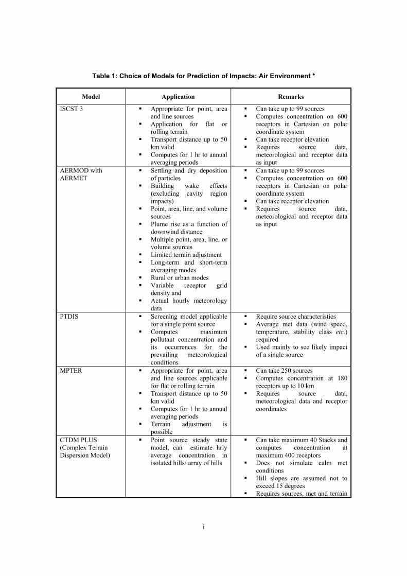
i
Table 1: Choice of Models for Prediction of Impacts: Air Environment *
Model Application Remarks
ISCST 3 Appropriate for point, area
and line sources
Application for flat or
rolling terrain
Transport distance up to 50
km valid
Computes for 1 hr to annual
averaging periods
Can take up to 99 sources
Computes concentration on 600
receptors in Cartesian on polar
coordinate system
Can take receptor elevation
Requires source data,
meteorological and receptor data
as input
AERMOD with
AERMET
Settling and dry deposition
of particles
Building wake effects
(excluding cavity region
impacts)
Point, area, line, and volume
sources
Plume rise as a function of
downwind distance
Multiple point, area, line, or
volume sources
Limited terrain adjustment
Long-term and short-term
averaging modes
Rural or urban modes
Variable receptor grid
density and
Actual hourly meteorology
data
Can take up to 99 sources
Computes concentration on 600
receptors in Cartesian on polar
coordinate system
Can take receptor elevation
Requires source data,
meteorological and receptor data
as input
PTDIS Screening model applicable
for a single point source
Computes maximum
pollutant concentration and
its occurrences for the
prevailing meteorological
conditions
Require source characteristics
Average met data (wind speed,
temperature, stability class etc.)
required
Used mainly to see likely impact
of a single source
MPTER Appropriate for point, area
and line sources applicable
for flat or rolling terrain
Transport distance up to 50
km valid
Computes for 1 hr to annual
averaging periods
Terrain adjustment is
possible
Can take 250 sources
Computes concentration at 180
receptors up to 10 km
Requires source data,
meteorological data and receptor
coordinates
CTDM PLUS
(Complex Terrain
Dispersion Model)
Point source steady state
model, can estimate hrly
average concentration in
isolated hills/ array of hills
Can take maximum 40 Stacks and
computes concentration at
maximum 400 receptors
Does not simulate calm met
conditions
Hill slopes are assumed not to
exceed 15 degrees
Requires sources, met and terrain
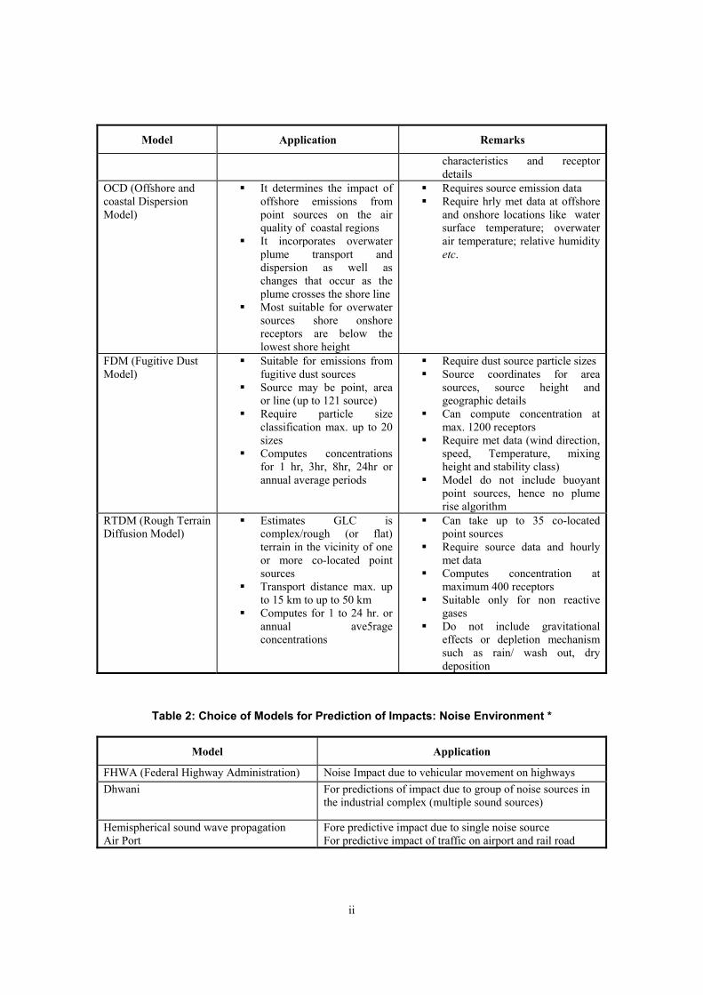
ii
Model Application Remarks
characteristics and receptor
details
OCD (Offshore and
coastal Dispersion
Model)
It determines the impact of
offshore emissions from
point sources on the air
quality of coastal regions
It incorporates overwater
plume transport and
dispersion as well as
changes that occur as the
plume crosses the shore line
Most suitable for overwater
sources shore onshore
receptors are below the
lowest shore height
Requires source emission data
Require hrly met data at offshore
and onshore locations like water
surface temperature; overwater
air temperature; relative humidity
etc.
FDM (Fugitive Dust
Model)
Suitable for emissions from
fugitive dust sources
Source may be point, area
or line (up to 121 source)
Require particle size
classification max. up to 20
sizes
Computes concentrations
for 1 hr, 3hr, 8hr, 24hr or
annual average periods
Require dust source particle sizes
Source coordinates for area
sources, source height and
geographic details
Can compute concentration at
max. 1200 receptors
Require met data (wind direction,
speed, Temperature, mixing
height and stability class)
Model do not include buoyant
point sources, hence no plume
rise algorithm
RTDM (Rough Terrain
Diffusion Model)
Estimates GLC is
complex/rough (or flat)
terrain in the vicinity of one
or more co-located point
sources
Transport distance max. up
to 15 km to up to 50 km
Computes for 1 to 24 hr. or
annual ave5rage
concentrations
Can take up to 35 co-located
point sources
Require source data and hourly
met data
Computes concentration at
maximum 400 receptors
Suitable only for non reactive
gases
Do not include gravitational
effects or depletion mechanism
such as rain/ wash out, dry
deposition
Table 2: Choice of Models for Prediction of Impacts: Noise Environment *
Model Application
FHWA (Federal Highway Administration) Noise Impact due to vehicular movement on highways
Dhwani For predictions of impact due to group of noise sources in
the industrial complex (multiple sound sources)
Hemispherical sound wave propagation
Air Port
Fore predictive impact due to single noise source
For predictive impact of traffic on airport and rail road

iii
Table 3: Choice of Methods for Prediction of Impacts: Water Environment *
Model Application Remarks
Estuary models/
estuarial Dynamic
model
It is simulates tides, currents, and discharge in shallow,
vertically mixed estuaries excited by ocean tides,
hydrologic influx, and wind action
Tides, currents in estuary are simulated
Dynamic model
Dynamic Water
Quality Model
It simulates the mass transport of either
conservative or non-conservative quality
constituents utilizing information derived from the
hydrodynamic model Bay-Delta model is the
programme generally used.
Up to 10 independent quality parameters of either
conservative or non-conservative type plus the
BOD-DO coupled relationship can be handled
Dynamic model
HEC -2 To compute water surface profiles for stead7y, gradually:
varying flow in both prismatic & non- prismatic channels
SMS Lake circulation, salt water intrusion, surface water profile
simulation model
Surface water Modelling
system Hydrodynamic
model
Table 4: Choice of Models for Prediction of Impacts: Land Environment *
Model Application Remarks
Digital Analysis
Techniques
Provides land use / land cover distribution
Ranking analysis
for soil suitability
criteria
Provides suitability criteria for developmental
conversation activities
Various parameters viz. depth,
texture, slope, erosion status,
geomorphology, flooding hazards,
GW potential, land use etc. are
used.
Table 5: Choice of Methods for Prediction of Impacts: Biological Environment *
Name Relevance Applications Remarks
Aquatic Flora
Sample plot
methods
Density and relative
density
Density and relative
dominance
Average number of
individuals species per unit
area
Relative degree to which a
species predominates a
community by its sheer
numbers, size bulk or biomass
The quadrant sampling
technique is applicable in all
types of plant communities and
for the study of submerged,
sessile (attached at the base) or
sedentary plants
Frequency and
relative frequency
Plant dispersion over an area
or within a community
Commonly accepted plot size:
0.1 m2- mosses, lichens & other
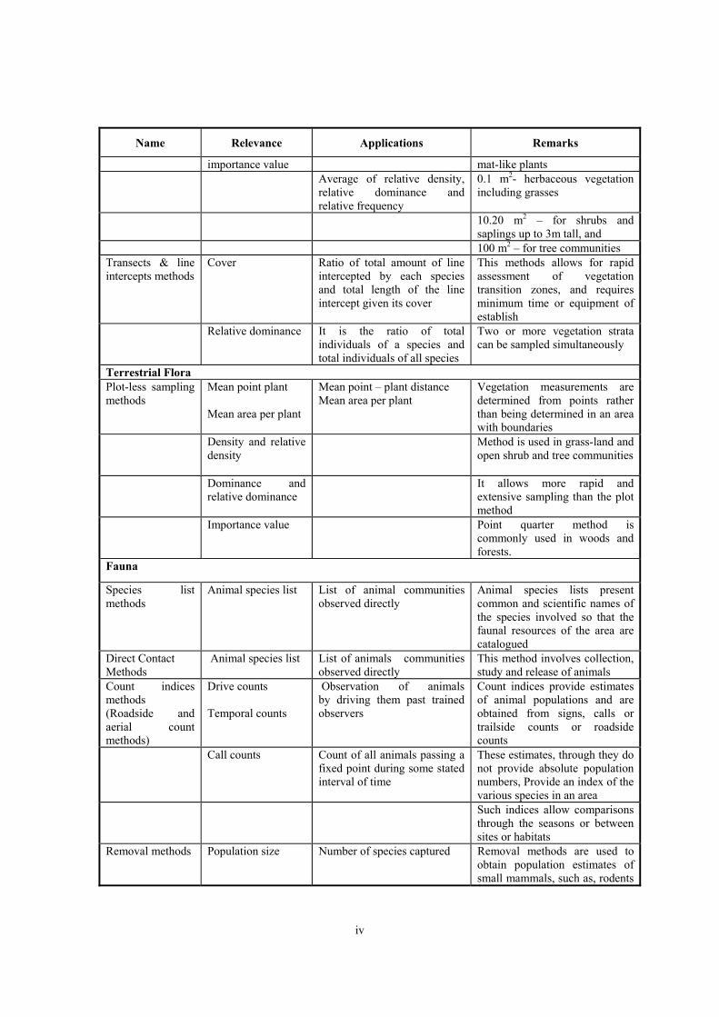
iv
Name Relevance Applications Remarks
importance value mat-like plants
Average of relative density,
relative dominance and
relative frequency
0.1 m2- herbaceous vegetation
including grasses
10.20 m2 – for shrubs and
saplings up to 3m tall, and
100 m2 – for tree communities
Transects & line
intercepts methods
Cover
Ratio of total amount of line
intercepted by each species
and total length of the line
intercept given its cover
This methods allows for rapid
assessment of vegetation
transition zones, and requires
minimum time or equipment of
establish
Relative dominance It is the ratio of total
individuals of a species and
total individuals of all species
Two or more vegetation strata
can be sampled simultaneously
Terrestrial Flora
Plot-less sampling
methods
Mean point plant
Mean area per plant
Mean point – plant distance
Mean area per plant
Vegetation measurements are
determined from points rather
than being determined in an area
with boundaries
Density and relative
density
Method is used in grass-land and
open shrub and tree communities
Dominance and
relative dominance
It allows more rapid and
extensive sampling than the plot
method
Importance value Point quarter method is
commonly used in woods and
forests.
Fauna
Species list
methods
Animal species list List of animal communities
observed directly
Animal species lists present
common and scientific names of
the species involved so that the
faunal resources of the area are
catalogued
Direct Contact
Methods
Animal species list List of animals communities
observed directly
This method involves collection,
study and release of animals
Count indices
methods
(Roadside and
aerial count
methods)
Drive counts
Temporal counts
Observation of animals
by driving them past trained
observers
Count indices provide estimates
of animal populations and are
obtained from signs, calls or
trailside counts or roadside
counts
Call counts
Count of all animals passing a
fixed point during some stated
interval of time
These estimates, through they do
not provide absolute population
numbers, Provide an index of the
various species in an area
Such indices allow comparisons
through the seasons or between
sites or habitats
Removal methods Population size Number of species captured Removal methods are used to
obtain population estimates of
small mammals, such as, rodents

v
Name Relevance Applications Remarks
through baited snap traps
Market capture
methods
Population size
estimate
(M)
Number of species originally
marked (T)
Number of marked animals
recaptured (t) and total
number of animals captured
during census (n)
N = nT/t
It involves capturing a portion of
the population and at some later
date sampling the ratio of
marked to total animals caught
in the population
Table 6: Choice of Methods for Prediction of Impacts: Socio-economic Aspect *
Name Application Remarks
Extrapolative
Methods
A prediction is made that is consistent with past and
present socio-economic data, e.g. a prediction based on
the linear extrapolation of current trends
Intuitive Forecasting
(Delphi techniques)
Delphi technique is used to determine environmental
priorities and also to make intuitive predictions through
the process of achieving group consensus
Conjecture Brainstorming
Heuristic programming
Delphi consensus
Trend extrapolation
and correlation
Predictions may be obtained by extrapolating present
trends Not an accurate method of making socio-economic
forecasts, because a time series cannot be interpreted or
extrapolated very far into the future with out some
knowledge of the underlying physical, biological, and
social factors
Trend breakthrough
precursor events
correlation and regression
Metaphors and
analogies
The experience gained else where is used to predict the
socio-economic impacts
Growth historical
simulation commonsense
forecasts
Scenarios Scenarios are common-sense forecasts of data. Each
scenario is logically constructed on model of a potential
future for which the degrees of “confidence” as to
progression and outcome remain undefined
Common-sense
Dynamic modeling
(Input- Out model)
Model predicts net economic gain to the society after
considering all inputs required for conversion of raw
materials along with cost of finished product
Normative Methods Desired socio-economic goals are specified and an
attempt is made to project the social environment
backward in time to the present to examine whether
existing or planned resources and environmental
programmes are adequate to meet the goals
Morphological analysis
technology scanning
contextual mapping
- functional array
- graphic method
Mission networks and
functional arrays decision
trees & relevance trees
matrix methods scenarios
* NOTE: (i) If a project proponent prefer to use any model other than listed, can do so, with prior
concurrence of concerned appraisal committee. (ii) Project-specific proposed prediction tools need to be
identified by the project proponent and shall be incorporated in the draft ToR to be submitted to the
Authority for the consideration and approval by the concerned EAC/SEAC.

ANNEXURE XIV Environmental, Health and Safety Measures

i
Mitigation Measures with respect to the Major Pollutants during Ship Recycling Activities
Identifying asbestos location onboard An enclosed chamber shall be created in the
ship where asbestos has been identified to avoid dispersion of air emission of asbestos
Limited access area shall be created. Vacuum system to filter air shall be
installed. Asbestos must be kept wet before and
during removal operations ACM must be removed as much as possible
in large portions without breaking it. When ACM is compounded with other
material, then the compounded material must be entirely removed without disturbing ACM and then ACM is transported to dedicated asbestos handling environment for removal.
Asbestos shall be packed in approved packaging system
Minimize the amount of workers exposed to the asbestos containing area
Clear asbestos area access regulations shall be defined.
Decontaminate (shower) workers and change set of clothes when leaving regulated area
The area must be covered to avoid air emission
All solid wastes resulting from asbestos removal process should be collected
Provision of adequate storage and disposal facilities
Provision of adequate storm water discharge
Employing specially designated asbestos workers and supervisors and ensure that employees comply to regulations regarding work with asbestos
Wearing head covering, gloves, foot covering and face shield/ goggles

ii
facilities, to avoid dispersion of asbestos in storm water runoff
Approved respirators should be provided for protection against airborne asbestos
Wearing a separate set of washable clothing
Create a separate area for paint-removal operations, with impermeable floor
Collect and contain all solid wastes resulting from paint removal process
Provide adequate storage/disposal facilities
Provide adequate storm water discharge facilities, to avoid contamination of storm water runoff
Determine if paint is toxic If paint is toxic, remove all toxic paint from
area to be cut prior to metal cutting Isolate area and create as much ventilation
as possible In working yard create a separate area for
paint-removal operations Create as much ventilation as possible For chemical paint and preservative
removers, protect skin, eyes and face For toxic solvents, wear approved respiratory
equipment and protect skin, eyes and face Create an enclosed chamber with point
extraction to avoid dispersion to air. To be integrated with air filtration system.
Limit access to the area Install vacuum system to filter air Create a separate area for paint removal
operations, with impermeable floor Create a dedicated area for storage of
paint/coatings residue Cover the area to avoid dispersion of air
emission Wear hoods and appropriate respirators Wear goggles or face shields
Determining the flammability of paint Removing all flammable paint from
area to be cut prior to metal cutting to prevent ignition
If using flammable liquids for chemical stripping, provide ventilation so that concentration of vapors is below 10% of lower explosive limit
Keep fire-extinguishing equipment within instant access
Identifying and labeling suspect materials and equipment
Carefully removing all PCB containing materials, and transporting to dedicated area
Disposing in controlled manner PCB containing materials shall be
carefully removed, without use of heat inducing equipment (such as
Specially designated personnel for identification and careful removal of PCB containing materials at source
Create a dedicated area for removal / overhauling of PCB containing materials
Create a dedicated area in for storage of PCB containing materials
Create a dedicated disposal area Appropriate protective clothing and

iii
torches) Keeping fire-extinguishing equipment
nearby
equipment
Adequate containment and pumping equipment
Adequate Oil transfer facilities Adequate storage and disposal
facilities Oil spill cleanup and notification
procedures Oil spill containment boom Oil spill cleanup equipment
Minimizing the use of manual labor at the source in the tanks for removal operations
Use of solvents to dissolve heavy weight sludge so that most oil and sludge can be pumped out.
Ventilating the compartments continuously Testing the compartment for oxygen and
presence of toxics, corrosives, irritants prior to manual cleaning
Use of personal protective equipments
Physical identification of location onboard
Cleaning oil tanks and compartments before hot work starts
Ventilating compartments and tanks continuously
Introducing hot work certification system
Testing the compartment for presence of flammable vapors before issuing certificate
Isolating the area and setting up “No Smoking” signs
Keeping fire extinguishing equipment immediately available
Determining pollutant concentrations prior to removal of the water
Adequate containment and pumping equipment
Adequate transfer operations facilities
Adequate storage and treatment facilities
Spill cleanup and notification procedures
Spill containment boom Spill cleanup equipment Change of ballast water
Minimizing the use of manual labor at the source in the tanks for removal operations (use of pumps)
Use of solvents to dissolve heavyweight sludge so that most residues can be pumped out Ventilate compartments continuously
Testing the compartment for oxygen and presence of toxics, corrosives, irritants prior to manual cleaning
Use of respiratory equipment (PPEs)
Physical identification of location of bilge and ballast water onboard
Cleaning oil tanks and compartments before hot works commences
Ventilating compartments and tanks continuously
Introducing a Hot-Works Certification system
Test compartment for presence of flammable vapors before issuing certificate
Isolate area and put up No Smoking signs Keep fire-extinguishing equipment immediately available
ANNEXURE XV Composition of EAC

i
Composition of the EAC
The Members of the EAC shall be Experts with the requisite expertise and experience in the
following fields /disciplines. In the event that persons fulfilling the criteria of “Experts” are not
available, Professionals in the same field with sufficient experience may be considered:
Environment Quality Experts: Experts in measurement/monitoring, analysis and
interpretation of data in relation to environmental quality
Sectoral Experts in Project Management: Experts in Project Management or Management of
Process/Operations/Facilities in the relevant sectors.
Environmental Impact Assessment Process Experts: Experts in conducting and carrying out
Environmental Impact Assessments (EIAs) and preparation of Environmental Management
Plans (EMPs) and other Management plans and who have wide expertise and knowledge of
predictive techniques and tools used in the EIA process
Risk Assessment Experts
Life Science Experts in floral and faunal management
Forestry and Wildlife Experts
Environmental Economics Expert with experience in project appraisal

___________________________________________________________________
ANNEXURE XVI
Best Practices & Latest Technologies available and reference

Best Practices & Latest Technologies available and reference
Ship breaking is carried out primarily in India, China, Bangladesh, and Pakistan, with Turkey
performing a handful of demolitions. The steel and scrap material make for valuable raw materials.
While the industry offers thousands of jobs for migrant workers (especially in South Asia), lack of
environmental and safety measures leads to high accident rates, heath risks, and pollution of coastal
areas. Moreover, hazardous materials like asbestos, polychlorinated biphenyls (PCBs), tributyl tin,
and large quantities of oils and oil sludge pose further risks.
The releases to the environment because of the ship breaking process can generally be attributed to
negligence in preparatory procedures preceding the dismantling process and the lack of ability to
collect, remove, or secure board materials.
The ISO standard:
These standards were developed by the ISO Technical Committee (TC) 8, Ships and marine
technology, subcommittee (SC) 2, Marine environment protection. They encourage an independent
initiative towards good practice through two guidelines. ISO/PAS 30006:2010 relates to ship
recycling management systems and it is concerned with diagrams to show the location of hazardous
materials onboard ships. The ISO/PAAS 30007:2010 addresses measures to prevent asbestos emission
and exposure during ship recycling.
The Hong Kong International Convention for Safe and Environmentally Sound Recycling of
Ships, 2009, adopted in May 2009:
The instrument regulates:
o The design, construction, operation and preparation of ships so as to facilitate safe
and environmentally sound recycling, without compromising their safety and
operational efficiency.
o The operation of ship recycling facilities in a safe and environmentally sound manner;
and
o The establishment of an appropriate enforcement mechanism for ship recycling
(certification / reporting).
An inventory of hazardous materials, specific to each ship, will be required from ships sent
for recycling. An appendix to the Convention provides a list of hazardous materials which are
prohibited or restricted in shipyards, ship repair yards, and ships of Parties to the Convention.
Ships will need to have an initial survey to verify the inventory of hazardous materials,
additional surveys during the life of the ship, and a final survey prior to recycling.
Moreover, ships will need to provide a “Ship Recycling Plan” to illustrate the manner in
which each ship shall be recycled, depending on particulars and the inventory. Parties to the
convention will have to take measures to ensure that ship recycling facilities comply with the
Convention.
In order to comply with the convention, the combined maximum ship recycling volume of the
states must, during the preceding 10 years, constitute not less than 3% of their combined
merchant shipping tonnage.
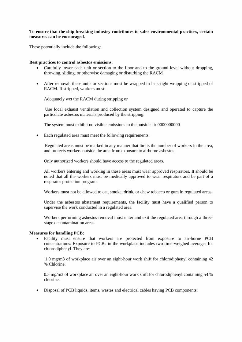
To ensure that the ship breaking industry contributes to safer environmental practices, certain
measures can be encouraged.
These potentially include the following:
Best practices to control asbestos emissions:
Carefully lower each unit or section to the floor and to the ground level without dropping,
throwing, sliding, or otherwise damaging or disturbing the RACM
After removal, these units or sections must be wrapped in leak-tight wrapping or stripped of
RACM. If stripped, workers must:
Adequately wet the RACM during stripping or
Use local exhaust ventilation and collection system designed and operated to capture the
particulate asbestos materials produced by the stripping.
The system must exhibit no visible emissions to the outside air.0000000000
Each regulated area must meet the following requirements:
Regulated areas must be marked in any manner that limits the number of workers in the area,
and protects workers outside the area from exposure to airborne asbestos
Only authorized workers should have access to the regulated areas.
All workers entering and working in these areas must wear approved respirators. It should be
noted that all the workers must be medically approved to wear respirators and be part of a
respirator protection program.
Workers must not be allowed to eat, smoke, drink, or chew tobacco or gum in regulated areas.
Under the asbestos abatement requirements, the facility must have a qualified person to
supervise the work conducted in a regulated area.
Workers performing asbestos removal must enter and exit the regulated area through a three-
stage decontamination areas
Measures for handling PCB:
Facility must ensure that workers are protected from exposure to air-borne PCB
concentrations. Exposure to PCBs in the workplace includes two time-weighed averages for
chlorodiphenyl. They are:
1.0 mg/m3 of workplace air over an eight-hour work shift for chlorodiphenyl containing 42
% Chlorine.
0.5 mg/m3 of workplace air over an eight-hour work shift for chlorodiphenyl containing 54 %
chlorine.
Disposal of PCB liquids, items, wastes and electrical cables having PCB components:

Depending on the item and its PCB concentration, the following kinds of disposal may be
required:
-Licensed incinerator
-Hazardous waste landfill
For electrical cables having PCB components, the facility may use shredders and separators to recover
recyclable metal that is intermixed with useless non-metallic material. Some shredder feedstock
contains hazardous materials, such as PCBs or asbestos, which can be difficult to contain and
effectively separate from the metals during the shredding and separation process. The facility ensures
that hazards are properly controlled during shredding and separation and also that metals and fluff are
properly managed thereafter.
Metal Cutting Practices and Procedures:
i) Metal cutting practices and procedures
The facility must ensure that all workers performing metal cutting of any type are wearing
suitable PPE for eyes, hands and body. Workers performing metal cutting must not wear
clothing with traces of flammable or combustible materials (e.g., grease or oil).
Fire prevention requirements:
The facility must eliminate the possibility of fire in confined spaces as a result of gas escaping
through leaking or improperly closed torch valves. This can be done by positively shutting off
the gas supply to the torch at some point outside the confined space whenever the torch is not
used, or left unattended for a substantial period of time (e.g., lunch hour). The torch and hose
must be removed from the confined space overnight and during the shift changes.
Testing before cutting:
o For drums, containers, or hollow structures which have contained flammable
substances, the facility must fill them with water or thoroughly clean them of such
substances, and ventilate and test them prior to cutting.
o The facility must provide a vent or opening in each drum, container, hollow structure,
or jacketed vessel for the release of any pressure, which may build up during heating.
o For structural voids such as skegs, bilge keels, fair waters, masts, booms, support
stanchions, pipe stanchions or railings, the facilities competent person must inspect
the object and, if necessary, test for the presence of flammable liquids or vapors and
non-flammable liquids that could heat up and cause pressure
Metal cutting in confined / enclosed spaces:
o The facility must provide workers with suitable mechanical ventilation or respiratory
PPE. Mechanical ventilation may consist of either a general mechanical ventilation
system or a local exhaust system
o General mechanical ventilation must have sufficient capacity and provide the number
of air changes necessary to maintain fumes and smoke within safe limits. Mechanical
ventilation or local exhaust ventilation is provided when cutting the Zinc-bearing base
or filler metals or metals coated with Zinc-bearing materials, Lead-based metals,
Cadmium-bearing filler materials, Chromium-bearing metals or metals coated with
Chromium-bearing materials
o Local exhaust ventilation or air line respirators are used when cutting metals
containing lead (other than as an impurity) or metals coated with lead bearing
materials, cadmium-bearing or cadmium-coated base materials, metals coated with
mercury-bearing materials
o If sufficient ventilation is not possible without blocking the means of access, workers
must be able to use air line respirators and maintain communication with a colleague
outside the confined space who will guide them in an emergency.
o Facility must provide the workers with local exhaust ventilation and air line
respirators regardless of whether this work is being performed in an enclosed space or
in the open air when working with beryllium-containing base or filler metals
Metal cutting in open areas:
o In open areas, workers at the facility can normally perform general metal cutting
without mechanical ventilation or respiratory PPE, provided,
− it is not done in confined or enclosed spaces and
− metals containing or coated with toxic materials are not being cut.
o Workers cutting the metals containing toxic materials in open air must wear filter-
type respirators
Further worldwide practices for recycling:
o Since single hull tankers have greater environmental risks than double hull vessels, single hull
tankers should be converted to double hull after a certain age, in order to avoid oil spills and
pollution from ships
o Steel deduced from tankers is commonly re-rolled into concrete reinforcing rods to sell to the
construction industry, sewage projects, as well as used for metal rods and the agricultural
industry. However, advanced countries completely melt the scrap with which they make fresh
steel.
Sources:
http://www.alertnet.org/thenews/newsdesk/IRIN/8c5aceec9683ac796df24b62b1acc696.htm
http://www.iso.org/iso/pressrelease.htm?refid=Ref1258
http://web.ansi.org/news_publications/news_story.aspx?menuid=7&articleid=2632
http://www.ban.org/Library/greenpeace-ban-iii-3e.pdf

Technical Guidance Manual for Ship Breaking Yard August 2010
REFERENCES
Reference Documents
Ministry of Environment and Forest, GoI - “Environment Impact Assessment Notification”
S.O.1533 dated 14th September 2006.
Ministry of Environment and Forest, GoI – “Environment Impact Assessment Notification
2006 – Amendment” S.O. 195 (E) dated 1st December, 2009.
Larry W. Canter, “Environmental Impact Assessment”, Second Edition, McGraw Hill,
University of Oklahoma, 1997.
Greenpeace International / Basel Action Network (BAN) - “The IMO Guidelines on Ship
Recycling Annotated”, 21st November 2003.
International Labor Organization - “Safety and Health in Ship Breaking: Guidelines for
Asian countries and Turkey, Bangkok”, 7-14 October 2003.
International Metal Workers’ Federation - Status of Ship Breaking Workers in India – A
Survey, (A Survey on Working and Socio-Economic conditions of Ship Breaking Workers in
India), IMF-FNV Project in India, 2004 – 2007.
International Maritime Organization - “The IMO’s Work on Ship Recycling”, Sokratis
Dimakopoulos.
U.S. Environmental Protection Agency - “A Guide for Ship Scrappers: Tips for Regulatory
Compliance”, Summer 2000.
International Association for Impact Assessment in Cooperation with Institute of
Environmental Assessment, UK – “Principles of Environmental Impact Assessment Best
Practice, 1996
Ministry of Environment & Forests, Supreme Court of India - “Report of the Committee of
Technical Experts on Ship Breaking Activities”, 30th August 2006.
Ministry of Environment and Forest, GoI – Charter on Corporate Responsibility for
Environment Protection Action Points for 17 Categories of Industries, CPCB, March 2003.
Supreme Court Monitoring Committee - “Comprehensive Code on Ship Recycling
Regulations”.
Supreme Court Monitoring Committee - “Management of Hazardous Waste”, Volume I,
November 2003 – October 2006.
Coastal Region and Small Island Papers, UNESCO, Bhavnagar University, South Gujarat
University, CSI consultants - “Impacts and Challenges of a large Coastal Industry”, Alang –
Sosiya Ship Breaking Yard, Gujarat, India.

Technical Guidance Manual for Ship Breaking Yard August 2010
Marine Environmental Emergency Preparedness and Response, Regional Activity Centre -
“Guidelines for Providing and Improving Port Reception Facilities and Services for Ship-
Generated Marine Litter in the Northwest Pacific Region”, Nowpap Merrac, north Pacific
Action Plan.
Oil companies International Marine Forum - “Ship Yard Safety”, April 1997.
IL & FS Ecosmart Limited - “Data Collection, Alang Sosiya Ship Breaking Yard”, Andheri
(East), Mumbai, June-July, 2008.
IL & FS Ecosmart Limited - “Housing Needs Assessment For Workers in Alang sosiya Ship
Breaking Yard”, Bhavnagar District, Gujarat, India, , Andheri (East), Mumbai, October 2008.
Ecosmart India Ltd., - Report on Secondary Data Collection for Environmental Information
Centre, submitted to Ministry of Environment and Forests, 28th March 2003
National Institute of Occupational Health - “Health Hazards in Ship Breaking Workers of
Alang”, An GMB-NIOH Collaborative Project, Ahmedabad, India.
The Greenpeace India - Deliberate, Organized, Systematic, Annual Report, 2005 – 2006.
“Heavy Metals content of Suspended Particulate Matter at World’s Largest Ship Breaking
Yard”, Alang-Sosiya, India, Published online: 22nd July 2006.
“Ship Breaking: A Background Paper”.
Referred Websites
http://en.hxlogistics.cn/LCLKnowledge/index.html
http://envfor.nic.in/cpcb/hpcreport/vol3b.htm
http://envfor.nic.in/cpcb/hpcreport/contents.htm
http://envfor.nic.in/divisions/iass/eia.htm
http://luckygroupindia.com/
http://www.csiwisepractices.org/?read=85
http://www.globalsecurity.org/military/world/india/alang-sby.htm
http://www.gmbports.org/news_news.htm
http://www.greenpeaceweb.org/shipbreak/
http://www.leyal.com.tr/ship.htm
http://www.iaia.org
http://www.ilo.org/public/english/protection/safework/sectors/shipbrk/shpbreak.htm

Technical Guidance Manual for Ship Breaking Yard September 2009
http://www.imd-gujarat.gov.in/
http://www.join.co.kr/Environmental%20Facilities/index_4.html
http://www.leyal.com.tr/ship.htm
http://www.osha.gov/index.html
http://www.osha.gov/SLTC/etools/shipyard/ship_breaking/index.html#Survey
http://www.sriaindia.com/types_of_waste.html

IL&FS Ecosmart Limited
Flat # 408, Saptagiri Towers
Begumpet
Hyderabad – 500 016
Ph: + 91 40 40163016
Fax: + 91 40 40032220