for the beacon proact 200 system · beacon user guide 2 ... if the primary pump does not run after...
TRANSCRIPT

TM
User Guide for the
Beacon ProActTM 200 System
BEACON recommends that this product, like all sump pump-
related products, be installed by or under the supervision of a
professional plumbing contractor. BEACON recommends that
you contact your local plumbing contractor for installation.

BEACON USER GUIDE
2
1. Important Safety Information ………………………………………… 3
2. Introduction ..…………………………………………………………….. 4
3. System Components ..………………................................................. 4
4. System Overview ………………………………………………………… 5
A. Single AC Pump Installation …………………………………….. 5
B. Dual AC Pump Installation ……………………………………….. 6
C. AC Primary Pump and DC Backup Pump …………………….. 7
5. Operating Mode Selection ……………………………………………. 8
6. How it Works ………………………………………………………………. 9
7. System Operation ……………………………………………………….. 14
A. Controls and Indicators …………………………………………… 14
B. Push Buttons …………………………………………………………. 15
C. Running a Manual Test ……………………………………………. 16
D. Pump Status Indicators ……………………………………………. 16
E. System Status Indicators ………………………………………….. 17
F. Audible Alarms ……………………………………………………… 18
G. System Connections ………………………………………………. 19
8. System Recalibration ……………………………………………………. 21
9. Wi-Fi Alarm Reporting Activation …………………………………….. 23
10. Limited Warranty ………………………………………………………… 24
11. FCC Compliance Statement …………….……………………………. 26
Table of Contents

3
BEACON USER GUIDE
1. Important Safety Information
Before use, read the following instructions carefully. Save this manual for
future reference, and keep it readily available and near the Beacon
ProActTM 200 system.
ELECTRICAL SPECIFICATIONS: 120VAC, 15.0Amp, 50/60HZ.
Supply voltage fluctuations not to exceed +/- 10 percent nominal
voltage. Pollution Degree: 2
ENVIRONMENTAL OPERATING CONDITIONS: This equipment is rated for
indoor use, up to 6,600ft (2,000m) altitude, operating temp. of 41° to 104°
F (15° to 40°C), maximum relative humidity 80% for temperatures up to
88°F ( 31°C) decreasing linearly to 50% relative humidity at 104°F ( 40°C).
WARNING: Risk of electrical shock!
To reduce the risk of electrical shock, only connect to a properly
grounded, grounding-type receptacle.
Position the controller such that the power cord can be easily
reached for detachment in case of an emergency.
Only use with pumps that are properly grounded and wired with a 3-
prong grounded plug.
Do not operate standing on wet floor/in water, or with wet hands.
Do not disassemble any of the Beacon ProAct 200 components.
Service and repair to be performed only by authorized service
personnel authorized by the manufacturer.
For safe operation, use only Beacon approved accessories.
When connecting to a battery backup pump, always follow the
safety instructions provided by the pump manufacturer.
Operating, installing, or maintaining this unit in any way that is not
specified by the manufacturer could result in serious personal injury
or damage to the equipment.
CARE AND CLEANING: If needed, clean the controller with only a damp
cloth.
For technical support contact:
Beacon Technical Systems, LLC
2860 Plane Rest Drive
Waukegan, Illinois 60084
Phone: (800) 968-6760
E-mail: [email protected]

BEACON USER GUIDE
2. Introduction
4
Congratulations! You have purchased the Beacon ProActTM 200 Sump
Pump Test and Monitoring System. The ProAct 200 system is a
sophisticated microprocessor-based test and monitoring system that
monitors 24/7 and proactively weekly tests AC sump pumps in single and
dual AC pump installations, and in AC primary sump pump and DC
battery backup sump pump installations, to warn of pump failure before
the pumps are needed.
Controller
Valve
Module
Water Level
Sensor
Current Sensor (only for use with Backup Battery)
3. System Components
The Beacon ProAct 200 Sump Pump Test and Monitoring System includes
the following components:
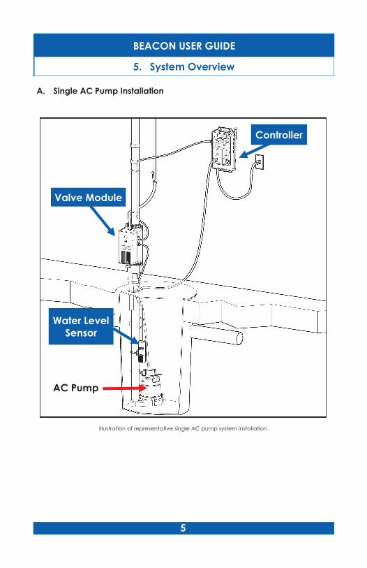
Controller
Valve Module
Water Level
Sensor
AC Pump
Illustration of representative single AC pump system installation.
BEACON USER GUIDE
5. System Overview
5
A. Single AC Pump Installation
BEACON USER GUIDE
6
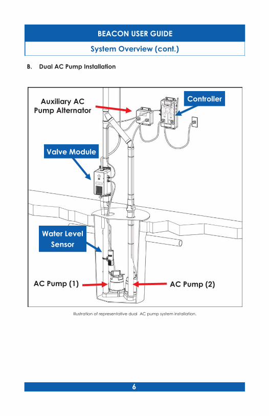
Controller
Valve Module
Water Level
Sensor
AC Pump (1)
Illustration of representative dual AC pump system installation.
B. Dual AC Pump Installation
AC Pump (2)
Auxiliary AC
Pump Alternator
System Overview (cont.)
BEACON USER GUIDE
7
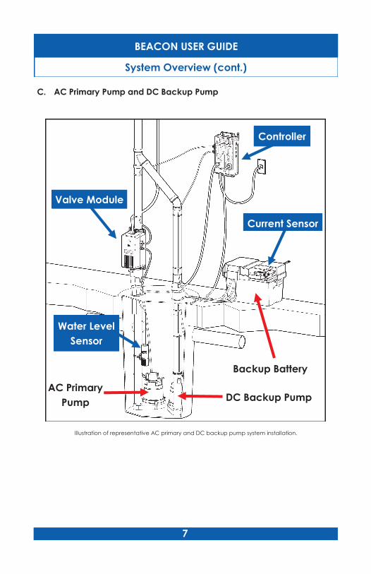
Controller
Valve Module
Water Level
Sensor
Current Sensor
AC Primary
Pump DC Backup Pump
Backup Battery
Illustration of representative AC primary and DC backup pump system installation.
C. AC Primary Pump and DC Backup Pump
System Overview (cont.)

BEACON USER GUIDE
8
5. Operating Mode Selection
Select the Operating Mode of the Controller that is appropriate
for the sump pump installation!
Press the red MODE SELECT button in the battery compartment ONCE.
This will select the Single Pump Mode, and only the Primary Pump status
light is amber.
Press the MODE SELECT button AGAIN to select the Dual Pump Mode.
Now both the Primary Pump and the Backup Pump status lights are
amber.
Press ONCE
Press AGAIN
Single Pump Mode
Dual Pump Mode
The Beacon ProAct 200 can operate in either:
(1) Single Pump Mode to monitor and test a single AC primary sump
pump (see page 5), or, with the addition of an auxiliary AC pump
alternator, two AC primary sump pumps (see page 6), or in
(2) Dual Pump Mode to monitor and test a single AC primary sump
pump and battery backup sump pump installation (see page 7).
Normally, in a dual sump pump installation, the Dual Pump Mode is
selected, as described in the Beacon Installation Guide. However, the
Single Pump Mode—not the Dual Pump Mode—should be selected if the
battery backup pump has an alarm that cannot be silenced or
deactivated or where the alarm does not only sound while the Backup
Pump is running. This will depend on the manufacturer and model of the
backup pump system. Backup pumps with an aural alarm that sounds
when the pump runs and continues until manually reset by the user may
be unsatisfactory for testing by the Beacon ProAct 200 system because
they subject the user to the nuisance of having to manually reset the
alarm after each manual or automatic test. In this case, the Single Pump
Mode should be selected.
BEACON USER GUIDE
9
When the Beacon ProAct 200 system is installed in either a single or a
dual pump installation, the system performs the following steps:
A. Conducting A Manual Test of the Monitored Sump Pump Installation
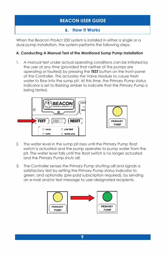
1. A manual test under actual operating conditions can be initiated by
the user at any time (provided that neither of the pumps are
operating or faulted) by pressing the TEST button on the front panel
of the Controller. This actuates the Valve Module to cause fresh
water to flow into the sump pit. At this time, the Primary Pump status
indicator is set to flashing amber to indicate that the Primary Pump is
being tested.
2. The water level in the sump pit rises until the Primary Pump float
switch is actuated and the pump operates to pump water from the
pit. The water level falls until the float switch is no longer actuated
and the Primary Pump shuts off.
3. The Controller senses the Primary Pump shutting off and signals a
satisfactory test by setting the Primary Pump status indicator to
green, and optionally (pre-paid subscription required), by sending
an e-mail and/or text message to user-designated recipients.
6. How It Works
BEACON USER GUIDE
10
5. Other alarm conditions are also signaled by the Controller, including
AC power loss, low ambient temperature, high water level, low
system battery and low backup battery (if installed).
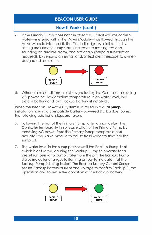
4. If the Primary Pump does not run after a sufficient volume of fresh
water—metered within the Valve Module—has flowed through the
Valve Module into the pit, the Controller signals a failed test by
setting the Primary Pump status indicator to flashing red and
sounding an audible alarm, and optionally (prepaid subscription
required), by sending an e-mail and/or text alert message to owner-
designated recipients.
When the Beacon ProAct 200 system is installed in a dual pump
installation having a compatible battery-powered DC backup pump,
the following additional steps are taken:
6. Following the test of the Primary Pump, after a short delay, the
Controller temporarily inhibits operation of the Primary Pump by
removing AC power from the Primary Pump receptacle and
actuates the Valve Module to cause fresh water to flow into the
sump pit.
7. The water level in the sump pit rises until the Backup Pump float
switch is actuated, causing the Backup Pump to operate for a
preset run period to pump water from the pit. The Backup Pump
status indicator changes to flashing amber to indicate that the
Backup Pump is being tested. The Backup Battery Current Sensor
senses Backup Battery current and voltage to confirm Backup Pump
operation and to sense the condition of the backup battery.
How It Works (cont.)
BEACON USER GUIDE
11
8. When the Backup Pump shuts down (after the preset run period), the
Controller signals satisfactory test results by setting the Backup Pump
status indicator green, and optionally (prepaid subscription
required), by sending an e-mail and/or text message to user-
designated recipients.
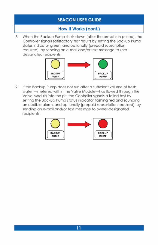
9. If the Backup Pump does not run after a sufficient volume of fresh
water —metered within the Valve Module—has flowed through the
Valve Module into the pit, the Controller signals a failed test by
setting the Backup Pump status indicator flashing red and sounding
an audible alarm, and optionally (prepaid subscription required), by
sending an e-mail and/or text message to owner-designated
recipients.
How It Works (cont.)
BEACON USER GUIDE
12
B. Conducting Periodic Automatic Tests of the Monitored Installation
Seven days (168 hours) after pressing the TEST CYCLE RESET button, and
every seven days thereafter, an automatic test of the sump pump
installation will be performed in the selected Single or Dual Pump Mode.
The following conditions must be met for an automatic test to begin:
168 hours have elapsed since the last test.
Active pump status indicators and the following system status
indicators indicate steady green: VALVE, FLOW, PRIMARY PUMP,
BACKUP PUMP (if installed), WATER LEVEL, and AC POWER.
The Primary Pump and Backup Pump (if installed) have not run for at
least ten minutes.
No manual test in progress.
The seven-segment Test Cycle Progress Display indicates
how many days have elapsed in the test cycle since the
last automatic test or since the last time the RESET TEST
CYCLE button was pressed. Each segment represents a
day; and the flashing segment is the current day in the
cycle.
As an example, when three days have passed since the last test and the
test cycle is in its fourth day, the three left-most segments are
continuously lit, and the fourth left-most segment is flashing.
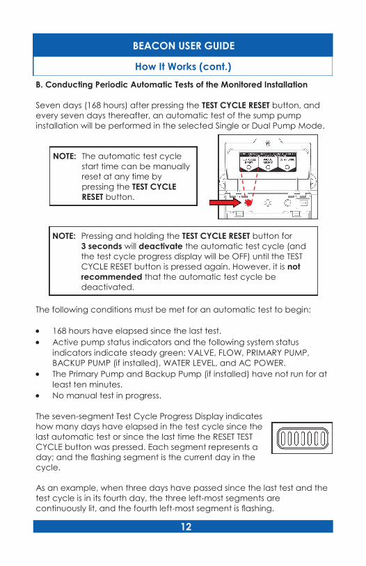
NOTE: The automatic test cycle
start time can be manually
reset at any time by
pressing the TEST CYCLE
RESET button.
NOTE: Pressing and holding the TEST CYCLE RESET button for
3 seconds will deactivate the automatic test cycle (and
the test cycle progress display will be OFF) until the TEST
CYCLE RESET button is pressed again. However, it is not
recommended that the automatic test cycle be
deactivated.
How It Works (cont.)
BEACON USER GUIDE
13
If the automatic test is delayed because of any of the above conditions
not being met (other than seven days not having elapsed since the last
automatic test), the seven segment Test Progress Display shows both the
first segment flashing (signifying the first day of a new test cycle), and the
seventh (last) segment flashing (signifying that the scheduled test is
delayed). When the scheduled test is finally performed, the flashing last
segment is extinguished (the first segment remains flashing).
C. The ProAct 200 System Continuously Monitors A Sump Pump
Installation As Follows:
1. In a single pump installation, if drain water in the sump pit rises to a
level which actuates the Beacon High Water Level Sensor, failure of
the Primary Pump is signaled by setting the Primary Pump status
indicator to flashing red, and sounding an audible alarm, and
optionally (prepaid subscription required), by sending an e-mail
and/or text message to user- designated recipients.
2. In a dual pump installation, if drain water in the sump pit rises to a
level which actuates the Backup Pump, and the Primary Pump is not
running, failure of the Primary Pump is signaled by setting the primary
pump status indicator to flashing red, and sounding an audible
alarm, and optionally (prepaid subscription required), by sending an
email or text message to user-designated recipients.
If water in the sump pump rises to a level which activates the High
Water Level Sensor, occurrence of a high water level and failure of
both the Primary Pump and Backup Pump is signaled by setting both
pump status indicators to flashing red and sounding an audible
alarm, and optionally (prepaid subscription required), by sending an
e-mail or text message to user-designated recipients.
How It Works (cont.)
BEACON USER GUIDE
14
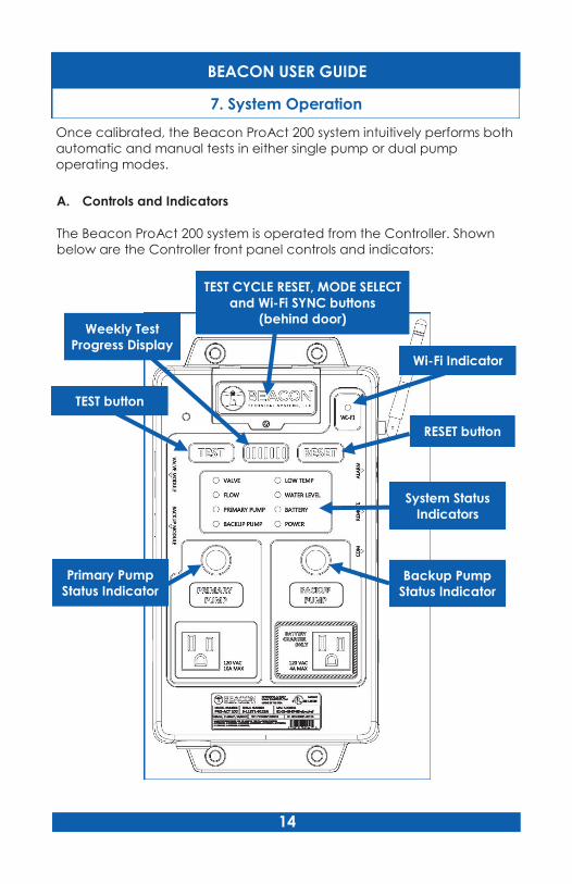
Once calibrated, the Beacon ProAct 200 system intuitively performs both
automatic and manual tests in either single pump or dual pump
operating modes.
A. Controls and Indicators
The Beacon ProAct 200 system is operated from the Controller. Shown
below are the Controller front panel controls and indicators:
RESET button
TEST button
Weekly Test
Progress Display
Wi-Fi Indicator
TEST CYCLE RESET, MODE SELECT
and Wi-Fi SYNC buttons
(behind door)
System Status
Indicators
Primary Pump
Status Indicator Backup Pump
Status Indicator
7. System Operation

BEACON USER GUIDE
15
B. Push Buttons
There are five push buttons on the Controller front panel and in the
battery compartment of the Controller for operating the system:
Button Description
RESET
If a test or calibration procedure is not in progress, press to
silence the audible alarm and set any flashing red pump
status indicator to solid red for 24 hours.
If a test or calibration procedure is in progress, press to stop
the current test or calibration procedure without completion.
If the valve module is open at this time, it will close (stopping
the flow of water into the sump pit).
Press and hold for 3 seconds or more to reset the following
system status indicators: VALVE, FLOW, PRIMARY PUMP,
BACKUP PUMP, and WATER LEVEL. In addition, Primary
Pump and Backup Pump status lights are set to display
amber (Pump untested) and audible alarms are silenced
for 24 hours, or until the failure reoccurs.
TEST Press to initiate a manual test of the sump pump installation,
and to calibrate the system following actuation of the MODE
SELECT button, provided no faults are present, no pumps are
operating and no test is in progress.
MODE SELECT
Press to enter the Configuration mode. Then press
repeatedly to toggle between single pump and dual
pump operating modes. The selected mode will be
indicated by the appropriate pump status indicator(s)
lighting amber. The dual pump mode will only be
selectable if the Backup Battery Current Sensor is installed.
Once the operating mode is selected, the TEST button
must be pressed to conduct a joint test and calibration of
the system in the selected operating mode.
TIMER RESET
Press to reset the seven day automatic test cycle to day one.
Press and hold for 3 seconds to cancel the automatic test
cycle. Press again to reinstate.
WI-FI SYNC Press and hold for 3 seconds to initiate configuration of the
Wi-Fi connection. The Wi-Fi status light will turn off.
System Operation (cont.)
BEACON USER GUIDE
16
C. Running a Manual Test
A manual test is the same as an automatic test except that it is initiated
by momentarily pressing the TEST button on the Controller front panel.
The following conditions must be met for the manual test to begin:
Active pump status indicators and the following system status
indicators indicate steady green: VALVE, FLOW, PRIMARY PUMP,
BACKUP PUMP (if installed), WATER LEVEL and AC POWER.
The Primary Pump and Backup Pump (if installed) are not operating.
No manual or automatic test is in progress.
A manual test does not effect or delay the scheduled automatic test
cycle.
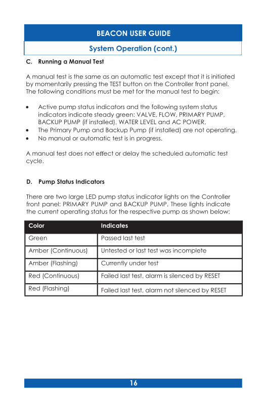
D. Pump Status Indicators
There are two large LED pump status indicator lights on the Controller
front panel: PRIMARY PUMP and BACKUP PUMP. These lights indicate
the current operating status for the respective pump as shown below:
Color Indicates
Green Passed last test
Amber (Continuous) Untested or last test was incomplete
Amber (Flashing) Currently under test
Red (Continuous) Failed last test, alarm is silenced by RESET
Red (Flashing) Failed last test, alarm not silenced by RESET
System Operation (cont.)
BEACON USER GUIDE
17
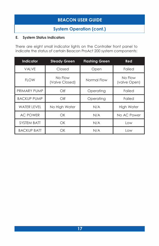
E. System Status Indicators
There are eight small indicator lights on the Controller front panel to
indicate the status of certain Beacon ProAct 200 system components:
Indicator Steady Green Flashing Green Red
VALVE Closed Open Failed
FLOW No Flow
(Valve Closed) Normal Flow
No Flow
(valve Open)
PRIMARY PUMP Off Operating Failed
BACKUP PUMP Off Operating Failed
WATER LEVEL No High Water N/A High Water
AC POWER OK N/A No AC Power
SYSTEM BATT OK N/A Low
BACKUP BATT OK N/A Low
System Operation (cont.)
BEACON USER GUIDE
18
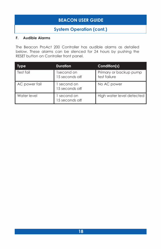
F. Audible Alarms
The Beacon ProAct 200 Controller has audible alarms as detailed
below. These alarms can be silenced for 24 hours by pushing the
RESET button on Controller front panel.
Type Duration Condition(s)
Test fail 1second on
15 seconds off
Primary or backup pump
test failure
AC power fail 1 second on
15 seconds off
No AC power
Water level 1 second on
15 seconds off
High water level detected
System Operation (cont.)
BEACON USER GUIDE
19
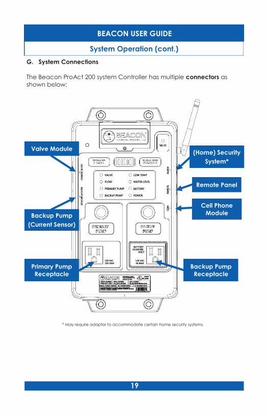
G. System Connections
The Beacon ProAct 200 system Controller has multiple connectors as
shown below:
Remote Panel
Backup Pump
(Current Sensor)
Valve Module (Home) Security
System*
Cell Phone
Module
Primary Pump
Receptacle
Backup Pump
Receptacle
* May require adaptor to accommodate certain home security systems.
System Operation (cont.)
BEACON USER GUIDE
20
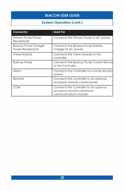
Connector Used For
Primary Pump Power
Receptacle
Connects the Primary Pump to AC power.
Backup Pump Charger
Power Receptacle
Connects the Backup Pump battery
charger to AC power.
Valve Module Connects the Valve Module to the
controller.
Backup Pump Connects the Backup Pump Current Sensor
to the Controller.
Alarm Connects the Controller to a home security
system.
Remote Connects the Controller to an optional
accessory remote control panel.
COM Connects the Controller to an optional
accessory remote cell phone
communications module.
System Operation (cont.)

BEACON USER GUIDE
21
In the event that a sump pump or other component is changed in the
sump pump installation, it will be necessary to recalibrate the Beacon
ProAct 200 system—to ensure accurate monitoring and testing of the
installation—by following the steps below and as also described in more
detail in Section 5 - CONTROLLER SETUP in the Beacon Installation Guide
for Dual Sump Pump Installation.
3. Select the Operating Mode of the Controller that is
appropriate for the sump pump installation!
Press the red MODE SELECT button in the battery compartment
ONCE. This will select the Single Pump Mode, and only the Primary
Pump status light is amber.
Press the MODE SELECT button AGAIN to select the Dual Pump Mode.
Now both the Primary Pump and the Backup Pump status lights are
amber.
Press ONCE
Press AGAIN
Single Pump Mode
Dual Pump Mode
1. Confirm that drain water is not currently flowing into the sump pit. If
necessary, temporarily install removable plugs or an alternative
blocking means in the active drain water inlets.
2. Temporarily activate the primary pump and the backup pump (dual
pump installation) by lifting their respective float switches to confirm
operability of the pumps and remove any residual water in the sump
pit.
8. System Recalibration

22
4. Press the TEST button on the Controller front panel to initiate the
automatic Calibration Cycle to adjust the Controller test cycle to the
specific sump pump installation.
5. During the Calibration Cycle, the Valve Module opens to admit fresh
water into the pit until the Primary Pump float switch is triggered and
the pump operates to pump water from the pit. During calibration of
the Primary Pump the Primary Pump status light flashes AMBER and
turns to steady GREEN when the calibration is successful.
6. In Dual Pump Mode, the Controller repeats the calibration procedure
for the Backup Pump. The Backup Pump status light flashes AMBER
and changes to steady GREEN when the calibration is successful*.
BEACON USER GUIDE
System Recalibration (cont.)
* NOTE: The Backup Pump is also calibrated in Single Pump Mode if
a Backup Pump is plugged into the Backup Pump
Receptacle. In that case, the Backup Pump status light also
flashes AMBER during the calibration, and only briefly
changes to GREEN before turning OFF when the calibration
is successful. (See also Section 5 in the Installation Guide for
AC Primary and DC Backup Dual Sump Pump Installation.)

23
7. Following the successful Calibration Cycle the Controller
automatically sets an automatic test interval. An automatic test will
now occur every 7 days (every168 hours) from the time the
Calibration Cycle was successfully completed.
10. Remove any plugs from the drain water inlet(s) and close the pit
cover.
9. Close the battery compartment door.
8. Wi-Fi Alarm Reporting Activation
Refer to the Beacon Wi-Fi Setup Guide for activation of the
comprehensive cloud-based monitoring and reporting service offered
by Beacon Technical Systems to owners of the Beacon ProAct 200
system. Prepaid subscription required. Go to:
SumpTest.com
8. If the Primary Pump was not manually activated before the
initiation of the Calibration Cycle because the sump pit is
sealed - or for any other reason - press the MODE SELECT
button ONCE to put the Controller in Standby Mode (both
lights OFF) again and then REPEAT Steps 1 through 7 of this
Section to ensure the system is properly calibrated with a
minimum water level in the pit.
Press ONCE
Standby Mode
BEACON USER GUIDE
System Recalibration (cont.)

24
BEACON USER GUIDE
10. Limited Warranty
Beacon Technical Systems, LLC (“Beacon”) warrants that for a period of
three years from the date of purchase of the Beacon ProAct™ Device
by the first purchaser of the Device, the ProAct Device will be free of
defects in materials and workmanship under normal use and service. This
Limited Warranty is conditioned upon proper storage and is void in its
entirety upon any improper or unreasonable use or maintenance,
accident, power surges, tampering or modification.
Within the warranty period, Beacon will, at its sole option, repair or
replace any defective parts, free of charge except for shipping and
handling costs. In order to obtain this service you must return the product
in its original packaging and carton, along with proof of purchase from
an authorized seller, directly to Beacon. Contact Beacon at 1-800-968-
6760 or [email protected] for a return authorization number and
shipping instructions. These instructions will include directions for properly
packing the product. If you need new packaging or a new carton,
either can be provided at cost upon request. Unfortunately, returns not
bearing an authorization number will be refused. Any replacement and/
or repaired device will be warranted for the remainder of the original
warranty or ninety (90) days from the date of shipment from Beacon,
whichever is longer. If Beacon is unable or unwilling to repair or replace,
Beacon will negotiate an equitable resolution such as a prorated refund
or credit.
This Warranty does not cover damages of any kind including damage to
property or for lost time or use or for the cost of having someone remove
or re-install the ProAct Device, or for the costs of travel to you and/or
from a servicer, and this Warranty shall not apply if the damages were
found to be caused by something other than defects in materials and
workmanship including but not limited to, if the ProAct Device: was
operated/stored in abnormal use or maintenance conditions; is
repaired, modified, or altered without Beacon’s express written pre-
authorization of such repair, modification or alteration; was subject to
abuse, neglect, electrical fault, improper handling, accident or acts of
nature; was not installed by a licensed plumber or similar professional
contractor; or was installed improperly.

BEACON’S SOLE RESPONSIBILITY SHALL BE TO REPAIR OR REPLACE THE
PROACT DEVICE WITHIN THE TERMS STATED ABOVE. THERE ARE NO
EXPRESS WARRANTIES EXCEPT AS LISTED UNDER THIS “LIMITED WARRANTY”.
BEACON IS NOT LIABLE FOR ANY LOSS OR DAMAGE OF ANY KIND,
INCLUDING BUT NOT LIMITED, TO ANY SPECIAL, INCIDENTAL OR
CONSEQUENTIAL DAMAGES RESULTING DIRECTLY OR INDIRECTLY FROM
THE USE OR FAILURE OF THIS PRODUCT, OR ARISING OUT OF ANY BREACH
OF THIS LIMITED WARRANTY OR OF ANY WARRANTY, EXPRESS OR IMPLIED.
TO THE MAXIMUM EXTENT PERMITTED BY LAW, THIS WARRANTY IS
EXCLUSIVE AND IN LIEU OF ALL OTHER WARRANTIES, WHETHER STATUTORY,
EXPRESS, OR IMPLIED (INCLUDING BUT NOT LIMITED TO, WARRANTIES OF
MERCHANTABILITY AND FITNESS FOR A PARTICULAR PURPOSE, AND
WARRANTIES ARISING FROM COURSE OF PERFORMANCE OR DEALING OR
USAGE OF TRADE), AND THE EXPRESS LIMITED WARRANTY PROVIDED IS
LIMITED TO THE THREE-YEAR PERIOD OF THE LIMITED WARRANTY.
We recommend that you record your model and serial number on this
page and keep this manual with your personal records along with proof
of purchase.
Model Name: ________________ Serial Number: ___________________________
Purchase Date: _______________ Seller: ___________________________________
25
BEACON USER GUIDE
Limited Warranty (cont.)

This device complies with Part 15 of the FCC Rules. Operation is
subject to the following two conditions: (1) this device may not
cause harmful interference, and (2) this device must accept any
interference received, including interference that may cause
undesired operation.
Caution: 1. To comply with FCC RF exposure compliance
requirements, a separation distance of at least 20 cm / 8
inches must be maintained between the antenna of this
device and all persons. 2. This transmitter must not be co-
located or operating in conjunction with any other
antenna or transmitter.
26
BEACON USER GUIDE
11. FCC Compliance Statement

[This page is intentionally left blank]
27
BEACON USER GUIDE

All supporting documentation
and instructional videos are
also available at:
sumptest.com
The Beacon ProActTM 200 system is covered by at least U.S. Patent No. 9,404,501.
Other U.S. and Foreign Patents Pending.
© 2016 - Beacon Technical Systems, LLC - All Rights Reserved.
[12/16]