for use in marathon* generators with pmg€¦ · generator automatic voltage regulator operation...
TRANSCRIPT

Generator Automatic Voltage RegulatorOperation Manual
Self Excited Automatic Voltage RegulatorUsing IGBT’s Insulated- Gate Bipolar Transistors
For use in Marathon* generators with PMG
* Use only for reference purpose only. This is not a Marathon Product
CALL US TODAY 1-888-POWER-58
REQUEST A QUOTE [email protected]
SHOP ONLINE www.genpowerusa.com
CALL US TODAY 1-888-POWER-58
REQUEST A QUOTE [email protected]
SHOP ONLINE www.genpowerusa.com
______________________________________________________________________________________
2 EA 08A-2000
480
220
110F-F+
PM
G
PM
G 0
UFUFRO STAB DROOPDIP VOLT TRIM
ON
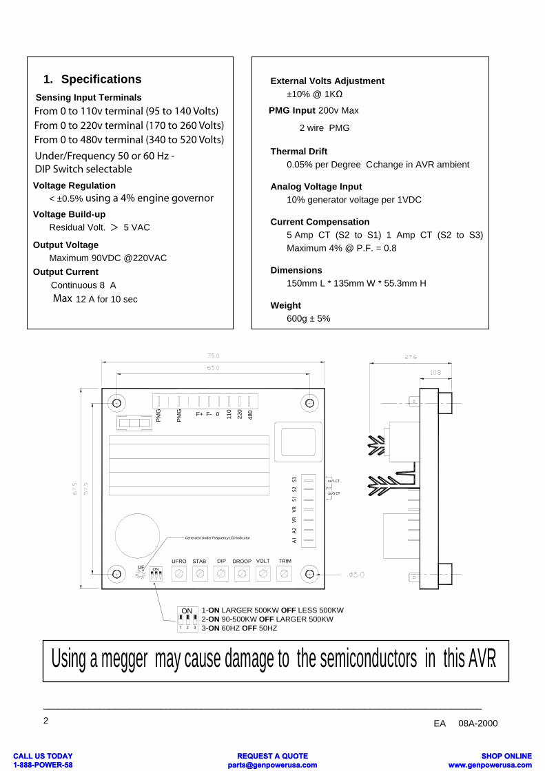
1. SpecificationsSensing Input Terminals
Voltage Regulation< ±0.5%
Voltage Build-upResidual Volt. > 5 VAC
Output VoltageMaximum 90VDC @220VAC
Output CurrentContinuous 8 A
12 A for 10 sec
External Volts Adjustment±10% @ 1KΩ
2 wire PMG
Thermal Drift
PMG Input 200v Max
0.05% per Degree Cchange in AVR ambient
Analog Voltage Input10% generator voltage per 1VDC
Current Compensation5 Amp CT (S2 to S1) 1 Amp CT (S2 to S3)Maximum 4% @ P.F. = 0.8
Dimensions150mm L * 135mm W * 55.3mm H
Weight600g ± 5%
Using a megger may cause damage to the semiconductors in this AVR.
A2
A1
VRVR
S2S1
S3 xx/1 CT
xx/5 CT
1 2 3
ON
1 2 3
From 0 to 110v terminal (95 to 140 Volts)From 0 to 220v terminal (170 to 260 Volts)From 0 to 480v terminal (340 to 520 Volts)
Under/Frequency 50 or 60 Hz - DIP Switch selectable
using a 4% engine governor
Max
1-ON LARGER 500KW OFF LESS 500KW2-ON 90-500KW OFF LARGER 500KW3-ON 60HZ OFF 50HZ
Generator Under Freguency LED indicator
CALL US TODAY 1-888-POWER-58
REQUEST A QUOTE [email protected]
SHOP ONLINE www.genpowerusa.com
CALL US TODAY 1-888-POWER-58
REQUEST A QUOTE [email protected]
SHOP ONLINE www.genpowerusa.com
______________________________________________________________________________________EA08A-2000 3
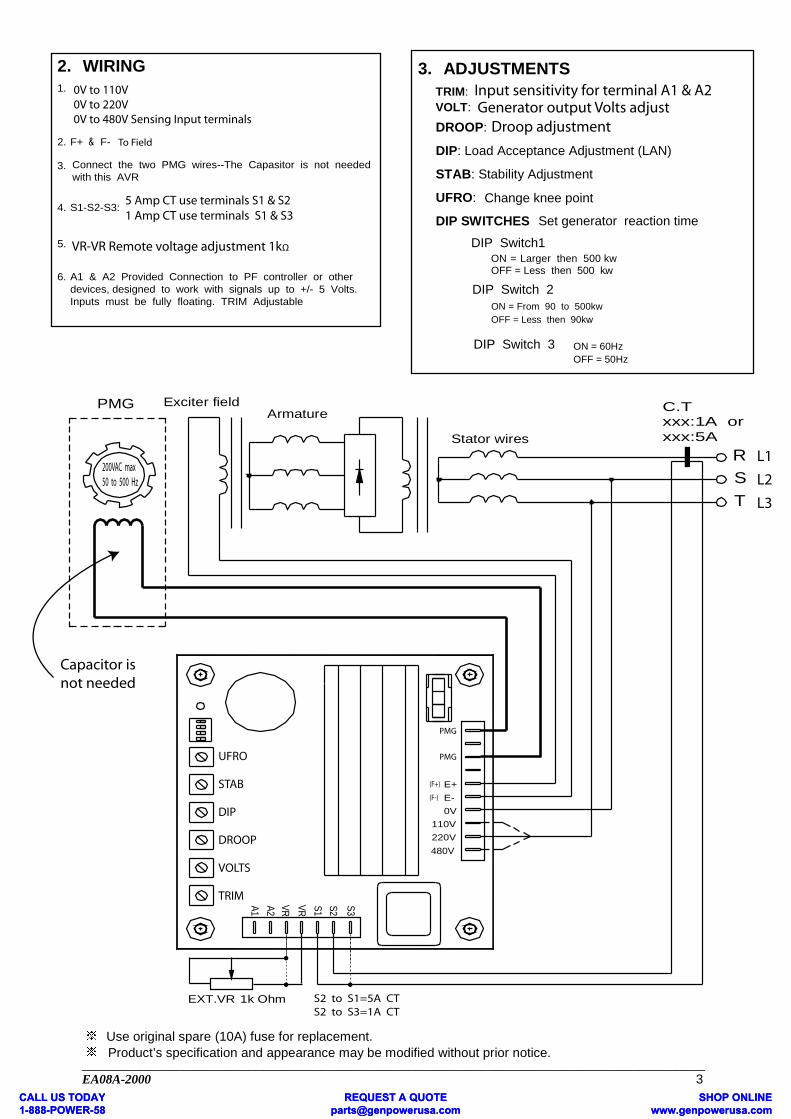
2. WIRING1.
2. F+ & F
Connect the two PMG wires--The Capasitor is not neededwith this AVR
-
3.
4. S1-S2-S3:
5.
6. A1 & A2 Provided Connection to PF controller or otherdevices, designed to work with signals up to +/- 5 Volts.Inputs must be fully floating. TRIM Adjustable
3. ADJUSTMENTSTRIM:VOLT:
DROOP:
DIP: Load Acceptance Adjustment (LAN)
STAB: Stability Adjustment
UFRO: Change knee point
DIP SWITCHESDIP Switch1
Set generator reaction time
ON = Larger then 500 kwOFF = Less then 500 kw.
DIP Switch 2ON = From 90 to 500kwOFF = Less then 90kw.
DIP Switch 3 ON = 60HzOFF = 50Hz
Armature
1k OhmEXT.VR
Exciter field
480V
S1 S2 S3
C.Txxx:1A orxxx:5A
E-
110V220V
0V
E+
Stator wires
ST
R
PMG
VRA2A1 VR
Use original spare (10A) fuse for replacement.Product’s specification and appearance may be modified without prior notice.
UFRO
STAB
DIP
DROOP
VOLTS
TRIM
200VAC max50 to 500 Hz
S2 to S1=5A CTS2 to S3=1A CT
(F+)
(F-)
PMG
PMG
To Field
Capacitor isnot needed
Input sensitivity for terminal A1 & A2Generator output Volts adjust
Droop adjustment
5 Amp CT use terminals S1 & S21 Amp CT use terminals S1 & S3
VR-VR Remote voltage adjustment 1kΩ
0V to 110V0V to 220V0V to 480V Sensing Input terminals
L1
L2
L3
CALL US TODAY 1-888-POWER-58
REQUEST A QUOTE [email protected]
SHOP ONLINE www.genpowerusa.com
CALL US TODAY 1-888-POWER-58
REQUEST A QUOTE [email protected]
SHOP ONLINE www.genpowerusa.com