forced air mobile diesel heating systems
TRANSCRIPT

Forced air mobile diesel heating systems.

Section 1: Location
Finding a location for the heater: It should be mounted upright, higher than the fuel,
placed to allow duct runs and within heater exhaust run limits. It can be mounted parallel or athwart ships. In gasoline powered boats, the heater must be located at a point higher than the engine intake manifold or carburetor. Never mount the heater in a gasoline engine room/space.
2© 2016 Two Mac Inc.
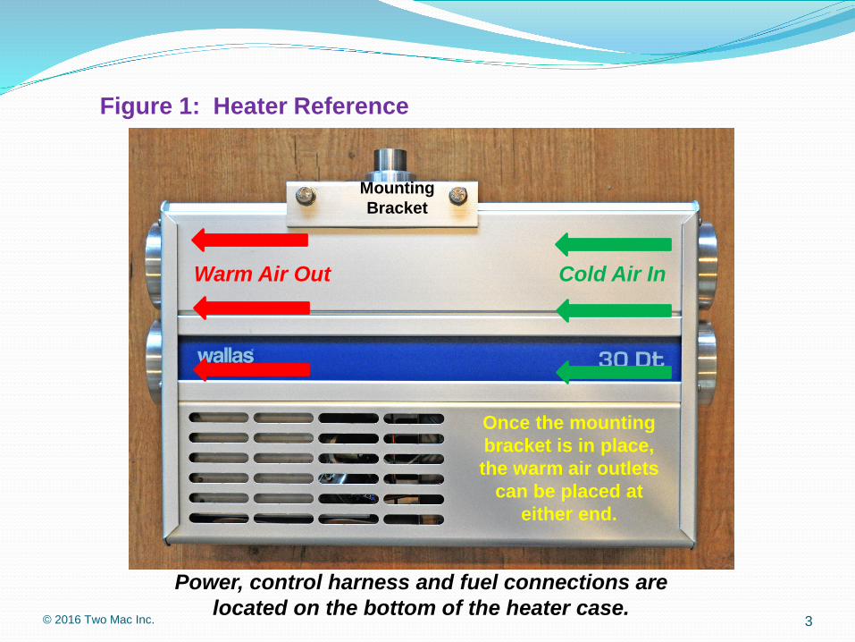
Figure 1: Heater Reference
Power, control harness and fuel connections are located on the bottom of the heater case.
3© 2016 Two Mac Inc.
MountingBracket
Warm Air Out Cold Air In
Once the mounting bracket is in place, the warm air outlets
can be placed at either end.

Safety Note:
Every boat or vehicle equipped with any kind of petroleum fueled engine or device should also be equipped with a CO (carbon monoxide) detector.
1. Should be capable of independent function.2. Should be tested for correct operation regularly.
4© 2016 Two Mac Inc.

Section 2: Exhaust System
Find a place for the exhaust through hull or house fitting: 1. Within 7’ exhaust run limits.2. Not facing the direction of travel. 3. Aft of the widest point of the beam. 4. Not on the back of the house to prevent “station wagon” effect. 5. Allowing for 12” rise above through hull inside the hull.6. 14” or more above the waterline.
See Figure 2.
5© 2016 Two Mac Inc.

Figure 2: Exhaust outlet locations
6© 2016 Two Mac Inc.
Note: Avoid placingexhaust outlet wherefenders will hang!

Section 2: Exhaust System
Make the exhaust run as necessary. Avoid tight turns and keep away from wiring or plastic objects.
Routing is not critical except for the last 12”, which should point vertically downward before connecting to the through hull fitting, forming a riser, preventing permanent water entry.
See the descriptions in figures 3. and 4.
7© 2016 Two Mac Inc.

Figure 3: Exhaust routings
8© 2016 Two Mac Inc.
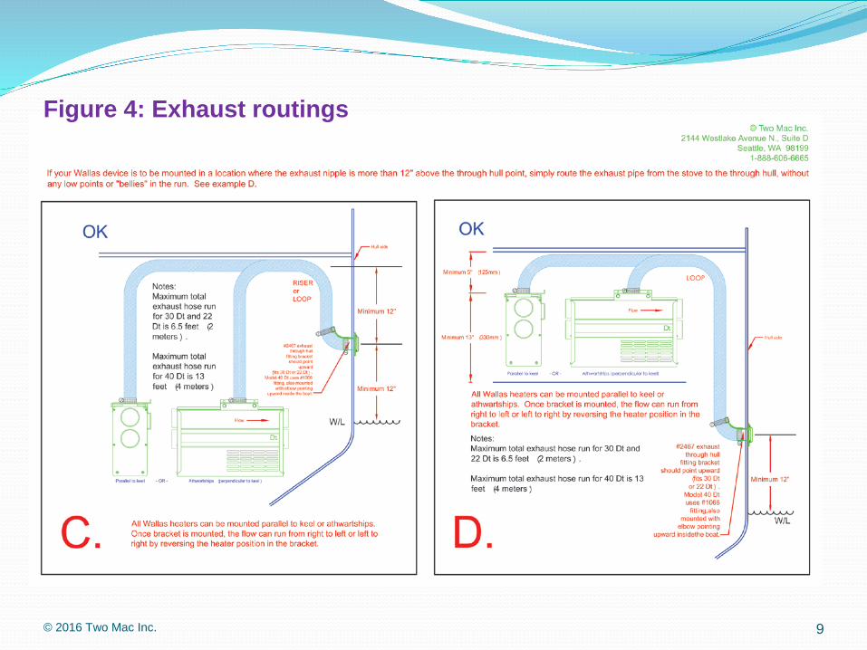
Figure 4: Exhaust routings
9© 2016 Two Mac Inc.
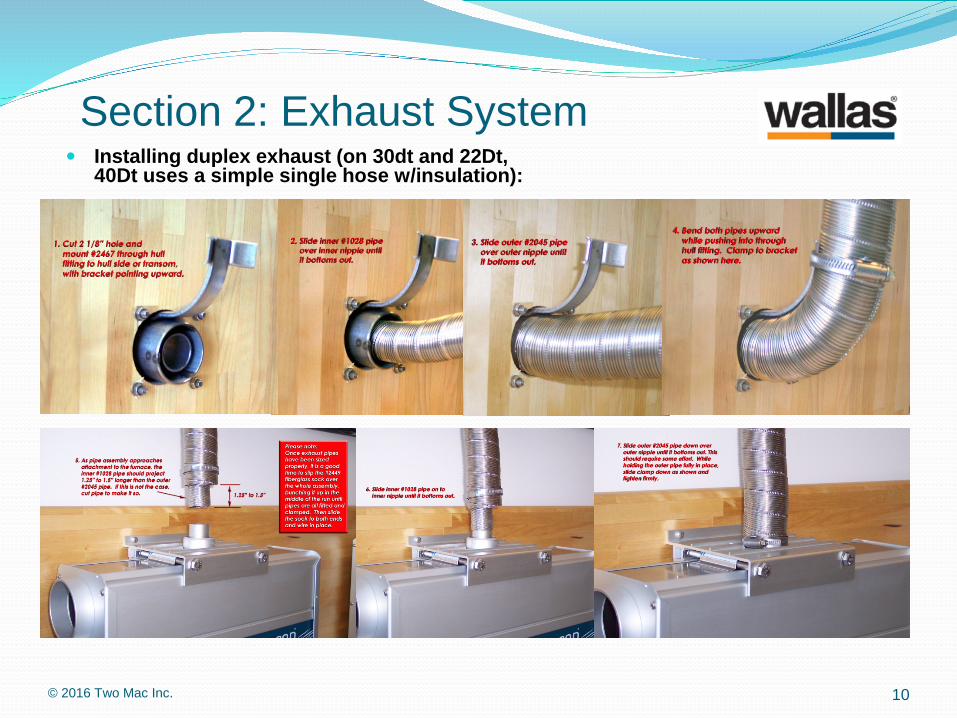
Section 2: Exhaust System Installing duplex exhaust (on 30dt and 22Dt,
40Dt uses a simple single hose w/insulation):
10© 2016 Two Mac Inc.

Section 3: Fuel connections
Make fuel connection. 1. If using a Wallas supplied day tank, just
connect the parts, shorten the fuel line from the filter end as appropriate to the installation, and attach the tank appropriately to prevent it moving.
2. If using a dedicated day tank from other suppliers, verify it is a top of tank pickup, use a Wallas filter and fuel line only. If the tank pickup ends in a ¼” hose barb, this will make connections easy.
11© 2016 Two Mac Inc.

Section 3: Fuel connections
3. If taking fuel from the main tank or a shared tank, assure the Wallas device has its own pickup.
a) You can use a #50011 custom drop tube to match an existing female fitting, or adapt to a breather fitting,
b) or use a #30011 drop tube to make a new penetration into the top of the tank.
12© 2016 Two Mac Inc.

Section 3: Fuel connections4. When connecting the fuel line to the fuel pump, ALWAYS hold
the fuel pump elbow with ViceGrip® or equivalent and use a 12 mm end wrench to tighten the fuel nut to the elbow VERY TIGHT. This will assure no air leaks. Do NOT turn the elbow relative to the pump body, as this will damage the pump metering.
13© 2016 Two Mac Inc.
You may find it easier to make the fuel connection before mounting the heater in the bracket, as shown here!
Section 4: Inlet duct connections B. If mounted in a locker/closet within the cabin, (See Figure 7),
you can choose to:1. Leave the inlets un-ducted (with grilles), drawing all inlet air from
the locker/closet. You must be sure enough makeup air flow into the locker/closet is available, meaning a minimum of 21 square inches. Some air flow into this area should be from outside (fresh air) and some from the cabin (return air). This air flow will act to warm and dry any items in the locker/closet, making it a “plenum” for inbound air.
2. Duct either the return air or fresh air or both into the heater inlets from outside the locker/closet. Remember, if the heater has clear inlet air flow, the outside of the heater itself will only get warm to the touch. If the locker is going to get indiscriminately “stuffed” with goods that might impede air flow, then ducting inlet air is important.
14© 2016 Two Mac Inc.

Figure 7:
15© 2016 Two Mac Inc.

Section 5: Outlet duct connections B. If mounted in a locker/closet within the cabin,
you can: (See Figure 7)1. Run ducts to two or more locations, normally low in the boat,
since heat will rise naturally. Ducts can all be full sized (3”) or the duct size can be reduced to 60mm when running to small spaces.
2. (OPTION) For defogging windows, a branch to the windows should always be located after a wye. In some applications, an in-line blower can be incorporated to boost flow to the windows for short durations.
16© 2016 Two Mac Inc.

Section 5: Outlet duct connections
D. Adding duct outlets beyond the two or three normally required for these heaters can add a lot of expense and labor. Sometimes it is worth the extra cost and work, but sometimes not. Excessive numbers of outlets can reduce apparent performance by slowing the time to heat cabin air due to losses into the surrounding structures of the ductwork. Heating the air first means you will heat the occupants more quickly. Less outlets leads to more aggressive stirring of the air, heating it more quickly.
17© 2016 Two Mac Inc.
Section 6: Electrical connections The Wallas power supply should be fuse or breaker
protected to 15 amps.1. The system will arrive with 13’ of 11 GA wire. If this is long
enough to reach the battery or main bus, it should be large enough to carry the starting amperage to start the heater.
2. Longer wire runs WILL require larger wire gauge.3. When testing the heater, a flashing yellow panel light may
indicate low voltage, possibly power lead drop due to undersized or too long power leads.
4. The heater should always be shut off using the control panel. Do not cut the power supply while the heater is running.
18© 2016 Two Mac Inc.

Section 7: Mounting the control panel The Wallas Dt heater control panel comes fitted
with a 20’ wire harness.1. The panel can be mounted with or without the supplied bezel.
Thermo control function will work either way.2. Mount the panel in a good location for thermo control
operation.a) Away from outside walls.b) At or about 4’ from the floorc) Where sunlight will not hit it directlyd) Away from heat or cold generating sources
19© 2016 Two Mac Inc.

Section 8: Lockout feature. The Wallas Dt heater has a lockout feature that locks the system up if it
has failed to start on two consecutive tries. On the third try, yellow, red and green panel lights will all flash rapidly for about five minutes. To clear lockout:
1. Leave panel on, all three lights must be flashing.2. While lights are flashing, kill power to the unit:
Pull the plug, remove the fuse or turn off breaker.3. Return power to the unit:
Reconnect the plug, replace the fuse or turn on breaker.4. Wait ten seconds, then push power button for two seconds, background
lights will go out.5. Heater is ready to start again, but before you do, investigate the system to
figure out why it has not been starting successfully: fuel, power, glow plug failure, etc.
6. When you are ready, push the power button once again for two seconds to start the system.
20© 2016 Two Mac Inc.

Special addendum for kerosene fired products:Unlike diesel heaters and stoves, Wallas kerosene fired products have a fuel return line. The device returns fuel/air vapor to the fuel tank when running.
21© 2016 Two Mac Inc.
In every case, the return line must make a steady, downhill run back to the fuel tank,with no low points or “bellies” in the run. This requirement will force the fuel tank to be located somewhere under and near the heater or stove.
Thank you!22© 2016 Two Mac Inc.