forest harvesting systems for biomass production harvesting systems for biomass production page 2...
TRANSCRIPT

Forest Harvesting Systems for Biomass Production
Renewable Biomass from the Forests of Massachusetts
Prepared for the Massachusetts Division of Energy Resources
& Massachusetts Department of Conservation & Recreation
With funding provided by the Massachusetts Technology Collaborative
Renewable Energy Trust
June 2007
Prepared By:
RE Consulting 20 Godfrey Drive Orono, ME 04473
207/949-4401
Innovative Natural Resource Solutions LLC 107 Elm Street, Suite 100-E
Portland, ME 04101 207/772-5440
www.inrsllc.com

Forest Harvesting Systems for Biomass Production Page 1
This material was prepared with financial support from the Massachusetts Technology Collaborative – Renewable Energy Trust. However, any opinions, findings, conclusions, or recommendations expressed are those of Innovative Natural Resource Solutions LLC and RE Consulting LLC, and do not necessarily reflect the views of the Massachusetts Technology Collaborative, the Renewable Energy Trust, the Massachusetts Division of Energy Resources or the Massachusetts Division of Conservation and Recreation, and do not constitute an endorsement of products or services mentioned. The analysis contained in this report is based upon our best professional judgement and on sources of information that we believe to be reliable. However, no representation or warrenty is made by Innovative Natural Resource Solutions LLC or RE Consulting LLC as to the accuracy or completeness of any information contained herein. Nothing in this report is, or should be relied upon as, a promise or representation as to the future. This report is part of a larger project, the Massachusetts Sustainable Forest Bienergy Initiative, that received funding from the U.S. Department of Energy. This report was prepared as an account of work sponsored by an agency of the United States Government. Neither the United States Government nor any agency thereof, nor any of their employees, makes any warranty, express or implied, or assumes any legal liability or responsibility for the accuracy, completeness, or usefulness of any information, apparatus, product, or process disclosed, or represents that its use would not infringe privately owned rights. Reference herein to any specific commercial product, process, or service by trade name, trademark, manufacturer, or otherwise does not necessarily constitute or imply its endorsement, recommendation, or favoring by the United States Government or any agency thereof. The views and opinions of authors expressed herein do not necessarily state or reflect those of the United States Government or any agency thereof.
Forest Harvesting Systems for Biomass Production Page 2
Numerous forest industry professionals provided input into the creation of this report, including individuals from the logging and trucking, forest management, equipment manufacturing and wood-energy generation industries and academia. In particular, the following individuals provided time and expertise in the preparation of case studies which appear in the appendices of this report:
• Timothy Beaulieu (Vice President of Operations -- Prentiss & Carlisle Co., Inc.) • Ray Berthiaume (Operations Forester -- Wagner Forest Management, Ltd.) • Eric Dumond (Procurement Supervisor – Boralex, Inc.) • Jeffrey Eames (President -- Fort Mountain Companies) • Clifford Lane (Co-owner -- JML Trucking & Excavating) • Dean Young (President -- Dean A. Young Forestry)
Additionally, the individuals listed below served as reviewers for this report. Their insights and helpful suggestions provided many improvements to the report’s content. Any opinions, findings, conclusions or recommendations expressed are those of Innovative Natural Resource Solutions LLC and RE Consulting LLC and do not necessarily reflect the views of or serve as an endorsement by the reviewers.
• Jeff Benjamin (Assistant Professor of Forest Operations Science -- School of Forest Resources, University of Maine)
• Christopher Nichols (Vice President -- Seven Islands Land Company) • Hugh Violette (Project Forester -- Orion Timberlands LLC)
Acknowledgements & Disclosures

Forest Harvesting Systems for Biomass Production Page 3
Introduction Pages 4 – 5 1. In-Woods Biomass Conversion Pages 6 – 36 1.1 Harvesting Pages 6 – 21 1.2 Accumulation Page 22 1.3 Processing Pages 23 – 26 1.4 Transport Pages 27 – 29 1.5 Biomass Conversion Systems Pages 30 – 34 1.6 Ownership Distribution Pages 35 – 36 2. Applicability to Operations in Massachusetts Pages 37 – 44 2.1 Description of Forest Resource Infrastructure Pages 37 – 39 2.2 Description of Logging & Land Clearing Infrastructure Page 40
2.3 Recommended Biomass Conversion Systems Pages 41 – 44 3. Framework to Consider the Biomass Conversion Systems-Contractor’s Perspective Pages 45 – 47 3.1 Production Balancing Page 45 3.2 Fit with Existing Operations Page 46 3.3 New or Used Equipment Page 46 3.4 Risk Management Pages 46 – 47 4. Role of the Public Sector in Promoting & Supporting Biomass Conversion Operations Pages 48 – 50 4.1 Promote a Healthy & Stable Wood-Energy Industry Page 48 4.2 Lower Ownership Costs through Interest Rate Reductions Page 48 4.3 Establish a Cost Share Program to Reduce Start-Up Costs Pages 49 – 50 4.4 Facilitate Knowledge Transfer & Other Education Related Activities Page 50 Appendixes
A. Biomass Conversion Systems Page 51 B. JML Trucking & Excavating Case Study Page 58 C. Prentiss & Carlisle Co., Inc. Case Study Page 62 D. Dean A. Young Forestry Case Study Page 69 E. Boralex, Inc. Case Study Page 74 F. Fort Mountain Companies Case Study Page 78 G. References Page 85
Table of Contents

Forest Harvesting Systems for Biomass Production Page 4
Forest biomass facilities require wood-based material to generate energy. In particular, facilities need the material to be within a specified size range, below a maximum moisture content value, and exclude contaminated1 material (see Figure 1 for a generic biomass fuel specification). With this in consideration, wood-based materials suitable for biomass energy are the following: manufacturing waste (e.g., sawdust, chips, bark, etc.); harvesting residue (e.g., branches, tops, and stumps); and whole-trees. While manufacturing waste is included as a supply source in many wood-energy facilities, it is unlikely that it in itself would be capable of supporting a large wood-energy industry because of limited supply2 and competing uses (e.g., pulp and paper, animal bedding, landscaping, etc.).
Figure 1: Generic Biomass Fuel Specification3
The challenge, from an operations perspective, is to find the most economic approach to convert trees and harvesting residue (e.g., branches, tops, and stumps) located in the forest, into a suitable product and deliver it to the wood-energy facility (Figure 2). The conversion includes tree harvesting, residue collection, comminution, and transportation. The purpose of this report is to provide insight into various approaches to convert in-woods biomass into suitable raw material for wood-energy facilities and to recommend specific approaches for operations located in the State of Massachusetts. This report also provides a framework for contractors to consider which approach is most applicable for their operations and makes recommendations for how the Massachusetts’ public sector can promote and support in-woods biomass conversion operations.
1 Contaminates include paints, adhesives, and other applied chemicals. 2 A study by the Massachusetts Biomass Energy Working Group indicated that primary and secondary wood manufactures produce approximately 11% of the available woody biomass in Massachusetts. Fallon, Mike & Breger, Dwayne. 2002. “The Woody Biomass Supply In Massachusetts: A Literature-Based Estimate”. Massachusetts Biomass Energy Working Group-Supply Subcommittee 3 Provided by Innovative Natural Resource Solutions LLC
Chip size
Maximum size: 2.2 inches in any direction Maximum percent oversize: 10% by volume, with a maximum size of 6”
Maximum fines (<+ 1/32”): 20%
Moisture Content
Average moisture content (as delivered): 40% to 55%
No fuel derived from construction or demolition debris, painted wood or engineered wood
Introduction

Forest Harvesting Systems for Biomass Production Page 5
Wood-Energy Material Needs Forest Material
Conversion
Requires Harvesting, Collection & Processing,
& Transportation
Wood-Energy Material Needs Forest Material
Conversion
Requires Harvesting, Collection & Processing,
& Transportation
Figure 2: Overview of the In-Woods Biomass Supply Problem
Forest Harvesting Systems for Biomass Production Page 6
The process to convert trees and harvesting residue into suitable material for wood-energy facilities requires tree harvesting, accumulation and processing of residue and trees, and transportation to the facility. There are a variety of approaches to each one of these steps, but not all are compatible with subsequent steps. The order of the steps is also influenced by the approach of each step, however, harvesting residue requires comminution or compaction prior to being transported because the material has a low bulk density4, and thus is difficult to achieve a full payload with. The driving force behind in-woods processing is the low-bulk density nature of harvesting residue. This section will explain options for each step and compile them into biomass conversion systems. 4 Bulk density = weight/volume
In-Woods Biomass Conversion

Forest Harvesting Systems for Biomass Production Page 7
1.1 Harvesting For the purposes of this report, harvesting trees includes processes required to deliver a delimbed and topped product to roadside. This includes felling, delimbing, transporting from the stump to the roadside landing (i.e., skidding or forwarding), and in some cases merchandizing. Exotic and harvesting systems uncommon to New England operations, such as cable and helicopter logging, are not included in this analysis. While this analysis is by no means exhaustive, it covers conventional harvesting systems, including the following (details on each system are on subsequent pages):
• Mechanical System • Non-Traditional Mechanical System • Mechanical Felling & Cable Skidder System • Manual Felling & Cable Skidder System • Manual Felling & Forwarder System • Manual Felling, Cable Skidder, & Pull-Through Delimber System • Cut-to-Length System

Forest Harvesting Systems for Biomass Production Page 8
Mechanical Harvesting System A mechanical harvesting system consists of three types of equipment: 1) Feller buncher; 2) Grapple skidder; and 3) Stroke delimber (Figure 3). A feller buncher severs each tree with a circular saw or shear and places them into piles. Each pile is oriented such that the butt end of each tree faces transport direction. A grapple skidder transports each pile to the roadside landing. At the landing, the grapple skidder drops the pile in front of the stroke delimber and returns to the woods for another pile. If needed, the grapple skidder will take a load of harvesting residue (e.g., branches and tree tops) back into the woods to minimize impact on wet areas. The stroke delimber removes the branches and tops the tree based on merchantable diameter specifications. Tree-length material is piled to the side to be further merchandized and harvesting residue is moved to the landing on the other side of the road if biomass is being utilized on the job. Otherwise, all of the harvesting residue is transported back into the woods by the grapple skidder or piled and burned after the harvest is complete. All components of this system are depicted in figure 4.

Forest Harvesting Systems for Biomass Production Page 9
Forest Road
Feller Buncher
Grapple SkidderStroke Delimber
Tree Length
= Standing Tree
= Stump
Harvesting Residue
Forest Road
Feller Buncher
Grapple SkidderStroke Delimber
Tree Length
= Standing Tree
= Stump
= Standing Tree
= Stump
Harvesting Residue
Feller Buncher Grapple Skidder Stroke DelimberFeller Buncher Grapple Skidder Stroke Delimber
Figure 3: Mechanical System Equipment5
Figure 4: Mechanical Harvesting System
5 Feller Buncher picture from: USDA Forest Service—North Central Research Station http://www.ncrs.fs.fed.us/fmg/nfmg/index.html

Forest Harvesting Systems for Biomass Production Page 10
Non-Traditional Mechanical Harvesting System The non-traditional mechanical harvesting system consists of three types of equipment: 1) Feller buncher; 2) Clambunk skidder; and 3) Stroke delimber (Figure 5). A feller buncher severs each tree with a circular saw or shear and places them into piles. Each pile is oriented such that the butt end of each tree faces transport direction. The clambunk skidder loads the piles into an inverted grapple with an on-board loader and transports them to the roadside landing. At the landing, the clambunk skidder drops the pile in front of the stroke delimber and returns to the woods for another pile6. If needed, the clambunk skidder will take a load of harvesting residue (e.g., branches and tree tops) back into the woods to minimize impact on wet areas. The stroke delimber removes the branches and tops the tree based on merchantable diameter specifications. Tree-length material is piled to the side to be further merchandized and harvesting residue is moved to the landing on the other side of the road if biomass is being utilized on the job. Otherwise, all of the harvesting residue is transported back into the woods by the clambunk skidder or piled and burned after the harvest is complete. Occasionally, this system is modified and the stroke delimber removes the branches and tops the trees in the woods, however, this is not the most efficient method if biomass is being utilized on the job. All components of this system are depicted in figure 6.
6 A clambunk skidder transports approximately three times the volume of a grapple skidder per turn. (Personal communication with Dan Philips-Oliver Stores)

Forest Harvesting Systems for Biomass Production Page 11
Forest RoadClambunk Skidder
Stroke Delimber
Tree Length
= Standing Tree
= Stump
Feller Buncher
Harvesting Residue
Forest RoadClambunk Skidder
Stroke Delimber
Tree Length
= Standing Tree
= Stump
= Standing Tree
= Stump
Feller Buncher
Harvesting Residue
Feller Buncher Clambunk Skidder Stroke DelimberFeller Buncher Clambunk Skidder Stroke DelimberFeller Buncher Clambunk Skidder Stroke Delimber
Figure 5: Non-Traditional Mechanical System Equipment7
Figure 6: Non-Traditional Mechanical Harvesting System
7 Feller Buncher and clambunk skidder pictures from: USDA Forest Service—North Central Research Station http://www.ncrs.fs.fed.us/fmg/nfmg/index.html

Forest Harvesting Systems for Biomass Production Page 12
Mechanical Felling & Cable Skidder System The mechanical felling and cable skidder system consists of two types of equipment: 1) Feller buncher; and 2) Cable skidder (Figure 7). A feller buncher severs each tree with a circular saw or shear and places them into piles. Each pile is oriented such that the butt end of each tree faces transport direction. Trees are often placed in the pile at different angles to make it easier for the cable skidder operator to place the cable around the butt of each tree. The cable skidder transports each pile to the roadside landing. Using a chainsaw, the cable skidder operator delimbs and tops the tree in the woods or at the roadside landing. If biomass is being utilized on the job, the trees are delimbed and topped at the roadside landing. When the trees are delimbed at the roadside landing, the cable skidder operator pushes the tree tops to the back of the landing and the tree-length material to the side. Note that in this approach, the tree-length material lays on top of the removed branches. Often two to three cable skidders are required to match the production of one feller buncher. All components of this system are depicted in figure 8.

Forest Harvesting Systems for Biomass Production Page 13
Forest Road
Feller Buncher
Cable Skidder
= Standing Tree
= Stump
Tree Length
Tree Tops
Branches
Forest Road
Feller Buncher
Cable Skidder
= Standing Tree
= Stump
= Standing Tree
= Stump
Tree Length
Tree Tops
Branches
Feller Buncher Cable SkidderFeller Buncher Cable SkidderFeller Buncher Cable Skidder
Figure 7: Mechanical Felling & Cable Skidder System Equipment8
Figure 8: Mechanical Felling & Cable Skidder System
8 Feller Buncher picture from: USDA Forest Service—North Central Research Station http://www.ncrs.fs.fed.us/fmg/nfmg/index.html Cable Skidder picture from: North Carolina Division of Forest Resources http://www.dfr.state.nc.us/

Forest Harvesting Systems for Biomass Production Page 14
Manual Felling & Cable Skidder System The manual felling and cable skidder system consists of two types of equipment: 1) Chain saw; and 2) Cable skidder (Figure 9). The manual feller severs the tree with a chain saw and directionally fells it so the butt end of each tree faces transport direction. The tree felling is either done by a separate feller or the cable skidder operator. The cable skidder winches the felled trees and transports them to the roadside landing. Using a chainsaw, trees are either delimbed and topped in the woods or at the roadside landing. If biomass is being utilized on the job, the trees are delimbed and topped at the roadside landing. When the trees are delimbed at the roadside landing, the cable skidder operator pushes the tree tops to the back of the landing and the tree-length material to the side. Note that in this approach, the tree-length material lays on top of the removed branches. The same approach generally applies for systems that replace the cable skidder with a farm tractor or bulldozer, however, sometimes the pulling capacity of these substitutes limits the option of transporting whole trees to the roadside landing. All components of this system are depicted in figure 10.

Forest Harvesting Systems for Biomass Production Page 15
Forest RoadCable Skidder
= Standing Tree
= Stump
Tree Length
Tree Tops
Branches
Cable Skidder
Forest RoadCable Skidder
= Standing Tree
= Stump
= Standing Tree
= Stump
Tree Length
Tree Tops
Branches
Cable Skidder
Chain Saw Cable SkidderChain Saw Cable SkidderChain Saw Cable Skidder
Figure 9: Manual Felling & Cable Skidder System Equipment9
Figure 10: Manual Felling & Cable Skidder System
9 Chain saw picture from: University of Maine--School of Forest Resources http://www.forest.umaine.edu/welcome.htm Cable Skidder picture from: North Carolina Division of Forest Resources http://www.dfr.state.nc.us/

Forest Harvesting Systems for Biomass Production Page 16
Manual Felling & Forwarder System The manual felling and forwarder system consists of two types of equipment: 1) Chainsaw; and 2) Forwarder (Figure 11). The manual feller severs the tree with a chain saw, removes the branches, and saws the tree into appropriate product lengths (e.g., 8 feet, 12 feet, 16 feet, etc.). Tree felling, delimbing, and processing are often done by a felling crew separate from the forwarder operator. The forwarder loads the logs onto the forwarder with a grapple loader and transports them to the roadside landing. The products are either loaded onto the ground at the roadside landing or directly onto an empty log-trailer (i.e., spot trailers). Note that in this approach, the branches and tree tops are distributed throughout the harvest block. All components of this system are depicted in figure 12.

Forest Harvesting Systems for Biomass Production Page 17
Forest Road
Processed Logs
= Standing Tree
= Stump
= Harvesting Residue
= Processed Logs
Forwarder
Forest Road
Processed Logs
= Standing Tree
= Stump
= Harvesting Residue
= Processed Logs
= Standing Tree
= Stump
= Harvesting Residue
= Processed Logs
Forwarder
Chain Saw ForwarderChain Saw Forwarder
Figure 11: Manual Felling & Forwarder System Equipment10
Figure 12: Manual Felling & Forwarder System
10 Chain saw picture from: University of Maine--School of Forest Resources http://www.forest.umaine.edu/welcome.htm Forwarder picture provided by Jeff Benjamin

Forest Harvesting Systems for Biomass Production Page 18
Manual Felling, Cable Skidder, & Pull-Through Delimber System The manual felling, cable skidder, and pull-through delimber system consists of three types of equipment: 1) Chain saw; 2) Cable skidder; and 3) Loader and pull-through delimber (Figure 13). The manual feller severs the tree with a chain saw and directionally fells it so the butt end of each tree faces transport direction. The tree felling is either done by a separate feller or the cable skidder operator. The cable skidder winches the felled trees and transports them to the roadside location. At the landing, the cable skidder unhooks the trees within reach of the loader and returns to the woods for another pile. The loader grabs each tree, or multiple trees at once if they are of similar form and quality, and pulls them through the delimber located on the harvesting-residue side of the landing and tops the tree with the toping saw located on the pull-through delimber. The loader places the tree-length material to the side and continues the process with the next tree(s). Occasionally, a feller buncher will be used for tree felling, and/or a grapple skidder will be used for transport to the roadside landing; however, the same general approach applies for the system. All components of this system are depicted in figure 14.

Forest Harvesting Systems for Biomass Production Page 19
Forest Road
= Standing Tree
= Stump
Cable Skidder Tree Length
Loader
Pull-Through Delimber
Forest Road
= Standing Tree
= Stump
= Standing Tree
= Stump
Cable Skidder Tree Length
Loader
Pull-Through Delimber
Chain Saw Cable Skidder Loader & Pull-Through DelimberChain Saw Cable Skidder Loader & Pull-Through DelimberChain Saw Cable Skidder Loader & Pull-Through Delimber
Figure 13: Manual Felling, Cable Skidder, & Pull-Through Delimber System Equipment11
Figure 14: Manual Felling, Cable Skidder, & Pull-Through Delimber System 11 Chain saw picture from: University of Maine--School of Forest Resources http://www.forest.umaine.edu/welcome.htm Cable Skidder picture from: North Carolina Division of Forest Resources http://www.dfr.state.nc.us/

Forest Harvesting Systems for Biomass Production Page 20
Cut-to-Length System The cut-to-length system consists of two types of equipment: 1) Processor; and 2) Forwarder (Figure 15). The processor severs the tree with a chain saw located on the felling head, removes the branches and saws the tree into appropriate product lengths (e.g., 8 feet, 12 feet, 16 feet, etc.). Typically, the branches and tree tops are left in the forwarder trail to minimize impact to the forest floor. The forwarder loads the logs onto the forwarder with a grapple loader and transports them to the roadside landing. The products are either loaded onto the ground at the roadside landing or directly onto an empty log-trailer (i.e., spot trailers). Note that in this approach, the branches and tree tops are distributed throughout the harvest block. All components of this system are depicted in figure 16.

Forest Harvesting Systems for Biomass Production Page 21
Forest Road
Forwarder
Processor
Processed Logs
= Standing Tree
= Stump
= Harvesting Residue
= Processed Logs
Forest Road
Forwarder
Processor
Processed Logs
= Standing Tree
= Stump
= Harvesting Residue
= Processed Logs
= Standing Tree
= Stump
= Harvesting Residue
= Processed Logs
Processor ForwarderProcessor ForwarderProcessor Forwarder
Figure 15: Cut-to-Length System Equipment12
Figure 16: Cut-to-Length System
12 Forwarder picture provided by Hugh Violette

Forest Harvesting Systems for Biomass Production Page 22
Bundler ForwarderBundler ForwarderBundler Forwarder
1.2 Accumulation of Harvesting Residue For the purposes of this report, accumulation includes all activities associated with collecting and piling harvesting residue. Accumulation of harvesting residue is only necessary if the material is not located at roadside, and thus is not required for all harvesting systems. Two general accumulation processes are the following:
• Bundler and forwarder • Forwarder
Bundler and Forwarder The bundler and forwarder approach uses two types of equipment: 1) Bundler; and 2) Forwarder (Figure 17). The bundler travels throughout the harvest job site and collects, compacts, and bales harvesting residue into biomass bundles. The forwarder loads the bundles onto the forwarder with a grapple loader and transports them to roadside.
Figure 17: Bundler & Forwarder Equipment13 Forwarder The forwarder approach uses a forwarder to collect harvesting residue throughout the job site. It loads tree tops and large branches into the back of the forwarder and transports them to the roadside landing. Occasionally a removable brush pan is added to the forwarder to minimize the amount of brush that falls out of the forwarder bunk or drags on the ground14. Continental Biomass Industries Inc., located in Newton, NH, offers a brush transport system for forwarders that compacts the harvesting residue, allowing for up to 10 ton loads15, and quick unloading16 at the landing17. 13 Pictures from: Rummer, B.; D. Len; & O. O’Brien. 2004. “Forest Residues Bundling Project, New Technology for Residue Removal”. Auburn, Alabama: USDA Forest Services, Southern Research Station. http://www.fs.fed.us/forestmanagement/WoodyBiomassUtilization/products/bundling/documents/bundler_report_final.pdf 14 Folkeman, Michael. 1989. “Handbook for Small-To-Medium Size Fuelwood Chipping Operations”. Forest Engineering Research Institute of Canada. HB-07 15 10 tons, or 4 cords, of wood is a typical forwarder load when transporting processed logs. 16 The brush transport system hydraulically dumps the load. 17 Continental Biomass Industries Inc. Retrieved from http://www.cbi-inc.com/pdfs/BTS_DS_DR11.pdf on February 19, 2007.

Forest Harvesting Systems for Biomass Production Page 23
1.3 Processing of Biomass Material For the purposes of this report, processing includes all activities associated with converting harvesting residue, or trees, into smaller pieces (e.g., hog fuel or chips). There are three general types of processing equipment:
• Tub Grinder • Horizontal Grinder • Whole-Tree Chipper
Tub Grinder A tub grinder processes harvestings residue into smaller pieces by means of a hammer mill (Figure 18) located at the bottom of the tub (Figure 19). Harvesting residue is placed in the top of the tub which rotates to feed the material into the hammer mill. A screen around the hammer mill limits oversize material from passing through to the conveyor system which either feeds directly into a chip-van or transport container, or is piled onto the ground to be loaded later. Some models of tub grinders are available on trailer or self-propelled track carriers.
Figure 18: Hammer Mill with Screen18 Figure 19: Tub Grinder19
Horizontal Grinder A horizontal grinder processes whole-trees or harvestings residue into smaller pieces by means of a hammer mill (Figure 18) located at the end of the feed table (Figure 20). Harvesting residue or whole-trees are placed on the feed table and brought to the hammer mill via a rugged conveyor. A screen around the hammer mill limits oversize material from passing through to the conveyor system which either feeds directly into a chip-van or transport container, or is piled onto the ground to be loaded later. Some models of horizontal grinders are available on trailer or self-propelled track carriers. 18 Picture from: Gemaco Sales LTD. http://www.gemacosales.com/index.html 19 Picture from: Rummer, Bob “Harvesting Energy from the Forest: New Technology, New Opportunities?” United States Forest Service-Forest Operations Research Unit. http://www.srs.fs.usda.gov/forestops/presentations/Bundling.pdf

Forest Harvesting Systems for Biomass Production Page 24
Disc Chipper Drum ChipperDisc Chipper Drum ChipperDisc Chipper Drum Chipper
Figure 20: Horizontal Grinder Figure 21: Whole-Tree Chipper Whole-Tree Chippers A whole-tree chipper (Figure 21) processes whole-trees or harvesting residue into chips by either a drum or disc type chipper (Figure 22). Harvesting residue or whole-trees are placed on the feed table and brought to the chipper by a rugged conveyor. Some smaller models do not have a feed table and thus need to be feed material more frequently. The chips are blown out of a chute directly into a chip-van or transport container. Piling chips on the ground is difficult, and thus less common, because it is not easy to contain the chips in a manageable pile. Loading chips from a pile on the ground also adds dirt and rocks to the chip load, which are not desirable by the energy facility. As with the grinders, some whole-tree chippers are available on trailer or self-propelled track carriers.
Figure 22: Drum & Disc Chippers20
Each of the grinding equipment can be fed material by the following equipment types/categories:
• Track-Type/Off-Road Loading Equipment • On-Board or Road-Based Loading Equipment
20 Figures originally from: Pottie, M. & Guimier D. 1985. “Preparation of Forest Biomass for Optimal Conversion”. Forest Engineering Research Institute of Canada. SR-32.

Forest Harvesting Systems for Biomass Production Page 25
Excavator Track-Type LoaderExcavator Track-Type Loader
It is theoretically possible to feed a whole-tree chipper with track-type/off-road loading equipment, however, this equipment is typically used to accumulate and transport harvesting residue short distance on the landing. Accumulating harvesting residue that is distributed throughout the landing increases the percentage of rocks and dirt that goes into the chipper, which in turn increases damage to chipper knives and replacement or sharpening frequency, thus increasing maintenance and repair costs and decreasing machine utilization. Thus for all practical purposes, chippers are typically loaded with on-board loaders or road-based loaders. Again, this is nothing inherent about the loading equipment but rather purely a relationship between the loading equipment used and how the harvesting residue was collected during the harvesting step. Track-Type/Off-Road Loading Equipment Track-type/off-road loading equipment refers to any device that is capable of traveling short-distances on off-road conditions, and accumulating and loading harvesting residue and/or whole-trees into a grinder. In the forest location, this generally refers to excavators with thumb attachments and track-type loaders (Figure 23). However, it is also possible on level terrain to use a front-end loader or skid-steer equipped with brush handling attachments or a forwarder. The important distinction is that these types of equipment are capable of moving and accumulating harvesting residue short distances, thus offering more flexibility in the harvesting step for utilization of harvesting residue because material does not need to be piled within the reach of an on-board or road-based loader.
Figure 23: Common Track-Type/Off-Road Loading Equipment21 On-Board or Road-Based Loading Equipment On-board loading equipment refers to loaders located on chipper or grinder carriers (Figure 24). Road-based loading equipment refers to loaders located on crane carriers (Figure 24). These loading approaches are limited by the loader reach, which for all practical purposes is a fixed distance from the road. Grinders and chippers are occasionally located on the landing when processing material, however, the machine must be moved and set-up again once all of the material within an on-board loader’s reach has been processed. Grinders or chippers on self-propelled track carriers ease this process, but loading material into a chip-van or transport container from hog fuel or chip piles that are scattered throughout the landing decreases utilization and can be an inefficient process. Further, track-type/off-road loading equipment can access more difficult terrain (i.e., backside of or downward sloping landings) than a grinder or chipper on a self-propelled track carrier. The distinction is that for these loading methods, the 21 Track-type loader picture from: Kellog, L.; C. Davis; M. Vanderberg; & C. Bolding. 2006. “Identifying and Developing Innovation in Harvesting and Transporting Forest Biomass”. Forest Products Society 60th International Convention. http://www.forestprod.org/am06kellogg.pdf

Forest Harvesting Systems for Biomass Production Page 26
Loader on a Crane Carrier On-Board LoaderLoader on a Crane Carrier On-Board Loader
harvesting residue must be piled within reach of the loading equipment during the harvesting step. Otherwise, the chipper or grinder would not be able to fully utilize the material when it arrives on the job site.
Figure 24: On-Board and Road-Based Loading Equipment22 In addition, there is an off-road/mobile chipping approach where a drum chipper and chip-bin equipped with a dumping mechanism are mounted on a forwarder (Figure 25). The forwarder travels throughout the harvest job site and feeds harvesting residue into the on-board chipper which blows the chips into the on-board chip-bin. When the on-board chip-bin is full, the forwarder travels back to the road and dumps the chip-bin into a chip-van or transport container (Figure 26). This approach is occasionally used in Scandinavian countries and in the Canadian Maritimes. Figure 25: Off-Road/Mobile Chipping Equipment23 Figure 26: Off-Road/Mobile Chipper Dumping Chips24
When taking into account all of the possible processing and loading combinations, there are six general possible processing systems:
• Tub Grinder & Track-Type/Off-Road Loading System • Tub Grinder & On-Board or Road-Based Loading System • Horizontal Grinder & Track-Type/Off-Road Loading System • Horizontal Grinder & On-Board or Road-Based Loading System • Whole-Tree Chipper & On-Board or Road-Based Loading System • Off-Road Chipping System
22 On-Board Loader picture from: Bandit Industries, Inc. http://www.banditchippers.com/ 23 Picture from: Bruks Klöckner http://www.bruks.com/English/index.asp 24 Picture from: Folkeman, Michael. 1989. “Handbook for Small-To-Medium Size Fuelwood Chipping Operations”. Forest Engineering Research Institute of Canada. HB-07

Forest Harvesting Systems for Biomass Production Page 27
1.4 Transportation
Transportation of chips or hog fuel from the forest location to an energy facility can be accomplished by truck with the following configurations:
• Tractor-Truck & Open Top Chip-Van • Tractor-Truck & Enclosed Chip-Van • Roll-On/Off Transport Containers
Tractor-Truck & Open Top Chip-Van The tractor-truck and open top chip-van configuration consists of a tractor-truck and a two or three axle open top chip-van (Figure 27). The open-top van configuration allows for top or rear loading of chips or hog fuel. Some vans are equipped with live or walking floors which allow for self-unloading at the energy facility. Otherwise, chip-vans are unloaded by chip-van dumpers (Figure 28).
Figure 27: Open Top Chip-Van Figure 28: Chip-Van Dumper25
Tractor-Truck & Enclosed Chip-Van The tractor-truck and enclosed chip-van configuration consist of a tractor-truck and a two or three axle enclosed chip-van (Figure 29). The enclosed chip-van can only be loaded with chips or hog fuel from the rear. Some vans are equipped with live or walking floors which allow for self-unloading at the energy facility. Otherwise, chip-vans are unloaded by chip-van dumpers (Figure 28).
25 Picture from: Rawlings, C.; B. Rummer; C. Seeley; C. Thomas; D. Morrison; H. Han; L. Cheff; D. Atkins; D. Graham; & K. Windell. 2004. “A Study of How to Decrease the Costs of Collecting, Processing and Transporting Slash”. Montana Community Development Corporation. http://www.srs.fs.usda.gov/pubs/biomass_cd/Publications/Pub606.pdf

Forest Harvesting Systems for Biomass Production Page 28
Figure 27: Enclosed Chip-Van Roll-On/Off Transport Containers The roll-on/off transport container configuration consists of modular containers and a straight-frame tractor equipped with an on-board hydraulic grapple (i.e., hook truck)26. The configuration can be operated with or without a pup-trailer, which is another trailer with a modular container that is pulled by the hook truck. The containers can be left at the forest location and loaded while the truck is in route with another load (i.e., spot-loaded) or it can be loaded when the truck arrives on the job site (Figure 30). The hook truck unloads the containers at the energy facility with the on-board hydraulic grapple (Figure 31). It should be noted that there is a modification to this configuration; where harvesting residue is loaded into the transport containers by a delimber or loader (Figure 32) and then transported a short distance to a centralized area where a grinder or chipper is located. The idea behind this modification, which is discussed in more detail in the reference link below, is to increase utilization of the grinder or chipper. The hook truck configuration can also be used to haul logs with log-bunk containers (Figure 33). Figure 30: Hook Truck Loading Container27 Figure 31: Hook Truck Unloading Container28 26 Rawlings, C.; B. Rummer; C. Seeley; C. Thomas; D. Morrison; H. Han; L. Cheff; D. Atkins; D. Graham; & K. Windell. 2004. “A Study of How to Decrease the Costs of Collecting, Processing and Transporting Slash”. Montana Community Development Corporation. http://www.srs.fs.usda.gov/pubs/biomass_cd/Publications/Pub606.pdf 27 Picture from: Rawlings, C.; B. Rummer; C. Seeley; C. Thomas; D. Morrison; H. Han; L. Cheff; D. Atkins; D. Graham; & K. Windell. 2004. “A Study of How to Decrease the Costs of Collecting, Processing and Transporting Slash”. Montana Community Development Corporation. http://www.srs.fs.usda.gov/pubs/biomass_cd/Publications/Pub606.pdf 28 Picture from: Rummer, Bob. 2005 “Options for Transporting Biomass”. United States Forest Service-Forest Operations Research Unit. http://www.srs.fs.usda.gov/forestops/presentations/biomasstransport.pdf

Forest Harvesting Systems for Biomass Production Page 29
Figure 32: Loading Harvest Residue into a Container29 Figure 33: Hook Truck Loading a Log-Bunk Container30 Biomass bundles can be transported by a tractor truck and a log-trailer (Figure 34). It is important to note, however, that the bundles must be comminuted before the energy facility can utilize them.
Figure 34: Log-Truck Transporting Biomass Bundles31
29 Picture from: Rawlings, C.; B. Rummer; C. Seeley; C. Thomas; D. Morrison; H. Han; L. Cheff; D. Atkins; D. Graham; & K. Windell. 2004. “A Study of How to Decrease the Costs of Collecting, Processing and Transporting Slash”. Montana Community Development Corporation. http://www.srs.fs.usda.gov/pubs/biomass_cd/Publications/Pub606.pdf 30 Picture from: Smallwood Utilization Network- Montana Community Development Corporation http://smallwoodnews.com/Projects/Rollon/index.htm 31 Pictures from: Rummer, B.; D. Len; & O. O’Brien. 2004. “Forest Residues Bundling Project, New Technology for Residue Removal”. Auburn, Alabama: USDA Forest Services, Southern Research Station. http://www.fs.fed.us/forestmanagement/WoodyBiomassUtilization/products/bundling/documents/bundler_report_final.pdf
Forest Harvesting Systems for Biomass Production Page 30
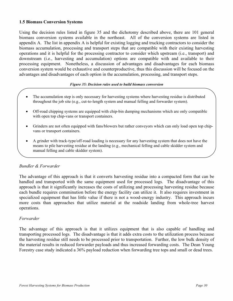
1.5 Biomass Conversion Systems Using the decision rules listed in figure 35 and the dichotomy described above, there are 101 general biomass conversion systems available in the northeast. All of the conversion systems are listed in appendix A. The list in appendix A is helpful for existing logging and trucking contractors to consider the biomass accumulation, processing and transport steps that are compatible with their existing harvesting operations and it is helpful for the processing contractor to consider which upstream (i.e., transport) and downstream (i.e., harvesting and accumulation) options are compatible with and available to their processing equipment. Nonetheless, a discussion of advantages and disadvantages for each biomass conversion system would be exhaustive and counterproductive, thus this discussion will be focused on the advantages and disadvantages of each option in the accumulation, processing, and transport steps.
Figure 35: Decision rules used to build biomass conversion
• The accumulation step is only necessary for harvesting systems where harvesting residue is distributed throughout the job site (e.g., cut-to-length system and manual felling and forwarder system).
• Off-road chipping systems are equipped with chip-bin dumping mechanisms which are only compatible
with open top chip-vans or transport containers.
• Grinders are not often equipped with fans/blowers but rather conveyors which can only load open top chip-vans or transport containers.
• A grinder with track-type/off-road loading is necessary for any harvesting system that does not have the
means to pile harvesting residue at the landing (e.g., mechanical felling and cable skidder system and manual felling and cable skidder system).
Bundler & Forwarder The advantage of this approach is that it converts harvesting residue into a compacted form that can be handled and transported with the same equipment used for processed logs. The disadvantage of this approach is that it significantly increases the costs of utilizing and processing harvesting residue because each bundle requires comminution before the energy facility can utilize it. It also requires investment in specialized equipment that has little value if there is not a wood-energy industry. This approach incurs more costs than approaches that utilize material at the roadside landing from whole-tree harvest operations. Forwarder The advantage of this approach is that it utilizes equipment that is also capable of handling and transporting processed logs. The disadvantage is that it adds extra costs to the utilization process because the harvesting residue still needs to be processed prior to transportation. Further, the low bulk density of the material results in reduced forwarder payloads and thus increased forwarding costs. The Dean Young Forestry case study indicated a 36% payload reduction when forwarding tree tops and small or dead trees.

Forest Harvesting Systems for Biomass Production Page 31
Grinders Grinders have some distinct advantages over whole-tree chippers, including the ability to efficiently process dirty wood and pile hog fuel on the ground to be loaded later by a bucket-style machine. Pile loading is not an efficient approach in-itself, but it can reduce the impact on trucking from grinder downtime. The disadvantages of grinders are that they produce an inferior product to chippers32 and conveyor-style loading limits trucking options to open top chip-vans or transport containers. This is a disadvantage because it potentially limits the supply of trucks and therefore could result in higher transport costs. In addition, a grinder on a self-propelled track carrier requires a lowbed trailer to move between job sites which increases moving costs and complicates logistics. Tub Grinder The advantage of the tub-grinder is that it is highly efficient at processing harvesting residue and is generally easier to perform maintenance on than horizontal grinders. The disadvantages are that it cannot process whole-trees or large branches without bucking, it has a tendency to project debris high into the air and thus may not be safe to use in residential settings, and it has a higher feed height than many horizontal grinders which may limit visibility or feasibility of certain loading methods (e.g., skid steer with brush attachment). Horizontal Grinder The advantages of the horizontal grinder are that it can process whole-trees and large branches efficiently and its low feed height increases the loading options, thus offering more operational flexibility. The low feed height also increases visibility for the loading operator. The disadvantages of the horizontal grinder are that it is less efficient when processing branches and stumps and it is more difficult to maintain than the tub grinder. Whole-tree Chipper Whole-tree chippers produce a high-quality (i.e., low variability in size) product and can load into open top or enclosed chip-vans and transport containers. The main disadvantage of a whole-tree chipper is that it is not efficient at processing dirty wood and requires wood to be free of rocks and other non-wood material. This means that whole-tree chippers cannot efficiently process material that has been pushed around and dug up by an excavator or any other track-type/off-road loading equipment. This is a disadvantage because it is costly to prepare harvesting residue in a manner that minimizes exposure to dirt and rocks. Dirt and rocks negatively impact whole-tree chippers because they increase the frequency for which chipper knives have to be changed, sharpened, and replaced. All of these results in increased mechanical downtime and maintenance and repair costs. Another disadvantage of a whole-tree chipper is that it generally needs to blow the chips directly into a chip-van or transport container because blowing the material onto the ground can be difficult to efficiently recapture, thus decreasing utilization, and often requiring separate equipment to load the material into a chip-van or transport container33. In addition, a whole-tree chipper on a self-propelled track carrier requires a lowbed trailer to move between job sites which increases moving costs and complicates logistics. 32 Hog fuel tends to contain more long-slivers and stringy material which can jam feeding systems at some energy facilities. Older energy facilities tend to pay less for hog fuel than chips. Newer facilities can handle the material better than older ones and do not discriminate on price for hog fuel. 33 Chippers require clean wood, and thus are generally limited to road-based or on-board loading, both of which generally utilize a grapple type head that is incapable of handling wood chips.

Forest Harvesting Systems for Biomass Production Page 32
Mobile/Off-Road Chipper The advantages of a mobile/off-road chipper are reduced moving costs and increased operational flexibility. The moving costs are reduced relative to grinding operations with track-type/off-road loading equipment because only one piece of equipment is moved. Further, the mobile/off-road chipper is capable of traveling and processing harvesting residue throughout the harvest job site. The disadvantages of the mobile/off-road chipper are increased ground compaction and cost. The mobile/off-road chipper is very heavy when full of chips, thus causing increased soil compaction. Studies by the Forest Engineering Research Institute of Canada (FERIC) have indicated that off-road chippers produce chips at a higher cost than road-based chippers34. Track-Type/Off-Road Loading Equipment The advantages of track-type/off-road loading equipment are that it can move harvesting residue short distances and it is capable of operating on a variety of terrain types. This means that the harvesting residue can be pushed out of the way and piled throughout the landing during the harvesting step, thus minimizing or eliminating any decrease in harvesting productivity associated with utilizing harvesting residue. Bucket-style loading equipment (e.g., excavator with thumb attachment) is also capable of loading hog fuel from the ground into an open top chip-van or transport container. Note that bucket-style loading equipment is not capable of loading an enclosed chip-van. The disadvantage of tract-type/off-road loading equipment is that it requires a low-bed trailer to move between job sites, and thus incurs higher moving costs than on-board or road-based loading equipment. Much of this equipment can also be used for other operations (i.e., an excavator can also be used for road-building or other construction activities), thus minimizing the dependency of the investment on the competitiveness of the wood-energy industry. On-Board or Road-Based Loading Equipment The advantage of on-board or road-based loading equipment is that it does not require a separate lowbed trip to move between job sites. By definition, on-board loading equipment moves at the same time as the chipper or grinder, and road-based loading configurations are either on a crane carrier with a designated truck or a self-contained trailer which is movable by a tractor truck. Road-based loading is a convenient means of loading a chipper or grinder because it is usually on the job site to load logs or tree-length material onto log trucks and therefore may not require additional investment or moving costs. On-board loading equipment has better visibility for tub grinders, however, visibility is limited for horizontal grinders and whole-tree chippers. The biggest disadvantage of on-board or road-based loading equipment is that the harvesting residue must be piled within reach of the loading equipment. This is a disadvantage for road-based equipment because space can quickly become a limiting factor on landings, where the harvesting residue to tree-length ratio is approximately two to one (see Prentiss & Carlisle case study). This decreases the total volume capable of being utilized on a job site and can decrease roundwood productivity35 of the harvesting system, thus increasing the costs of utilizing and processing harvesting residue. 34 Folkeman, Michael. 1989. “Handbook for Small-To-Medium Size Fuelwood Chipping Operations”. Forest Engineering Research Institute of Canada. HB-07 35 Roundwood productivity refers to the productivity of harvesting non-biomass related material (e.g., pulpwood, palletwood, bolt logs, sawlogs, etc.).

Forest Harvesting Systems for Biomass Production Page 33
Open Top Chip-Vans The advantage of open top chip-vans is that they can be loaded by a grinder (direct or pile loading method), whole-tree chipper36, or a mobile/off-road chipper configured with a bin dumping mechanism, thus increasing the options for backhauls. It is also possible to load logs into an open top chip-van. The disadvantage of open top chip-vans is that they are less durable than enclosed chip-vans, and thus incur higher maintenance and repair costs when operating on forest road conditions. Enclosed Chip-Vans The advantage of an enclosed chip-van is that they are more durable than open top chip-vans on forest road conditions. It is also relatively inexpensive to convert used dry-vans into enclosed chip-vans, thus decreasing the investment and risk associated with establishing a biomass processing operation (see Prentiss & Carlisle case study). The disadvantage of enclosed chip-vans is that they can only be loaded directly by a whole-tree chipper. Otherwise, a fan/blower system is necessary to achieve full payload. This limits the options for backhauls and thus potentially could result in higher transport costs. Roll On/Off Transport Containers The advantages of roll on/off transport containers are increased access to rural locations, increased operational flexibility, and compatibility with inter- and multi-modal transportation. Roll on/off transport containers are capable of traveling on and accessing many locations that traditional tractor truck and chip-van configurations cannot37. Some transport containers are designed to fit inside each other when empty, thus allowing multiple containers to be dropped off at a site at one time38. Idle time for the processing equipment is always reduced when chip-vans or containers are spotted on a job site (i.e., left on-site to be loaded while another load is in route to the energy facility), however, transport containers are cheaper to acquire39 and maintain40 than chip-vans. Containers are much easier to transfer between modes of transportation than chip-vans, which require unloading and reloading. The disadvantages of roll on/off transport containers are decreased payload and increased labor dependency per unit of delivered product. The payload for a 56 cubic yard container is approximately 15 tons, therefore a hook truck configured with a pup-trailer is capable of a total payload equal to 30 tons41. A study by the U.S. Forest Service, Montana Community Development Corporation, and Smurfit Stone Container Corporation concluded that “a roll on/off container system is not competitive with a regular highway chip van, unless part of that distance is inaccessible to the chip van”42.
36 A canvas top can be added to open-top chip vans if necessary. 37 Rawlings, C.; B. Rummer; C. Seeley; C. Thomas; D. Morrison; H. Han; L. Cheff; D. Atkins; D. Graham; & K. Windell. 2004. “A Study of How to Decrease the Costs of Collecting, Processing and Transporting Slash”. Montana Community Development Corporation. http://www.srs.fs.usda.gov/pubs/biomass_cd/Publications/Pub606.pdf 38 Anderson, Roy. 2006. “An Answer to Slash”. TimberWest September/October 2006 edition. http://smallwoodnews.com/Docs/Publicity/SlashStoryTW.pdf 39 According to Craig Rawlings, Wood Utilization and Marketing Network Agent -Montana Community Development Corporation, the containers cost approximately $13,000 each. Information acquired through personal communication on March 9, 2007. 40 Transport containers do not require license plates, and associated registration fees, or tires. 41 Personal communication with Craig Rawlings, Wood Utilization and Marketing Network Agent -Montana Community Development Corporation, on March 9, 2007. 42 Rawlings, C.; B. Rummer; C. Seeley; C. Thomas; D. Morrison; H. Han; L. Cheff; D. Atkins; D. Graham; & K. Windell. 2004. “A Study of How to Decrease the Costs of Collecting, Processing and Transporting Slash”. Montana Community Development Corporation. http://www.srs.fs.usda.gov/pubs/biomass_cd/Publications/Pub606.pdf

Forest Harvesting Systems for Biomass Production Page 34
Log Trailers & Biomass Bundles The main advantage of transporting biomass bundles on a log trailer from the forest to the energy facility, or a central processing location, is that it utilizes the same equipment and trailer configurations as those required to handle and transport processed logs. The approach also has related benefits of increased utilization of a grinder or chipper at the energy facility or central processing location. The disadvantages of this approach are increased handling (loading and unloading) costs and reduced payload. A forest-residue bundling study by the U.S. Forest Service found it was difficult to achieve greater than 50% of a legal payload when transporting biomass bundles43.
43 Rummer, B.; D. Len; & O. O’Brien. 2004. “Forest Residues Bundling Project, New Technology for Residue Removal”. Auburn, Alabama: USDA Forest Services, Southern Research Station. http://www.fs.fed.us/forestmanagement/WoodyBiomassUtilization/products/bundling/documents/bundler_report_final.pdf

Forest Harvesting Systems for Biomass Production Page 35
1.6 Ownership Distribution This section covers the possibilities for which the ownership and management of the components (e.g., harvesting, accumulation, processing, & transport) of a biomass conversion systems can be distributed. There are three general ownership distribution models for biomass conversion systems:
• One company owns the equipment for all conversion steps • Conversion steps are outsourced to different contractors • Wood-energy facility purchases the material FOB-shipping point44
One Company Owns All In this situation, one company owns all of the equipment involved with harvesting, accumulating (if necessary), processing, and transporting harvest residue and/or small and dead trees from the forest location to the wood-energy facility. The advantage of this approach is that the company is integrated into all aspects of the conversion process and therefore has control over the daily activities of all aspects of the operation. The disadvantage of this approach is that it requires the company to make large and in the case of an existing logging contractor, additional investments in equipment. Logging contractors with harvesting residue production levels below those required to economically operate a grinder or chipper will be required to find additional processing work. The bottom line is that adding a biomass processing operation to an existing or new logging operation increases the size of the investment required to enter the market and the complexity of managing operations. Outsourced Biomass Processing & Transportation This approach utilizes independent contractors for the processing and transport steps of the biomass conversion process. The advantage of this approach is that it spreads the risks and operational management over multiple entities. In this model, the logging contractor can specialize in harvesting and the biomass conversion contractor can specialize in harvest residue processing and transportation, opposed to the “one company owns all” model which requires the contractor to specialize in, and manage the day-to-day activities of, all aspects of the biomass conversion process. This approach also has the advantage to increase processing efficiencies and reduce moving costs per unit by processing material from multiple job sites in close proximity to one another. The disadvantage of this approach is the logging and biomass conversion contractors have limited control over each other’s operations, however, their actions can adversely affect each other. For example, if a logging contractor fills the harvesting residue side of the landing before the biomass conversion contractor arrives on the job site, the logging contractor must cease from continuing to utilize harvesting residue or move the material to another area where there is more room. In the first case, the biomass conversion contractor loses harvesting residue volume to process (i.e., incurs an opportunity cost) and incurs higher moving costs per unit of output. The logging contractor, in this case, has decreased production associated with disposal of additional harvesting residue and reduced landing space45. The latter causes equipment associated with the harvesting system to spend time moving material around, rather than processing trees, which in turn decreases machine utilization and increases costs. While this scenario is capable of occurring in the “one company owns all” approach, it is more common with the outsourced model because of limited control and, to a lesser extent, reduced communication between the components of the biomass conversion process. 44 FOB = Free on board. Ownership title transfers at the forest roadside. Processing and transportation costs are the responsibility of the buyer and are thus not included in the purchase price. 45 A landing full of harvesting residue can decrease the productivity of a stroke delimber operator because the back side of its boom hits the harvesting residue pile while delimbing trees, causing the operator to lose focus and interrupt the “rhythm of production”. Continually hitting the boom against the pile also could lead to structural damage of the boom.

Forest Harvesting Systems for Biomass Production Page 36
Harvesting Residue Sold FOB-Shipping Point to Wood-Energy Facility In this situation, the wood energy facility partially or fully owns the equipment required to process and transport harvesting residue from the forest roadside location to the wood-energy facility (see Boralex case study). The wood-energy facility buys the unprocessed material FOB-shipping point and thus incurs the responsibility and cost of processing and transporting the material. The advantage of this approach is that the logging contractor is able to sell material to wood-energy facilities without incurring any additional investment. This approach, similar to the outsourced approach discussed above, also allows for increased processing efficiencies because the wood-energy facility can process material from multiple job sites in close proximity to one another. Further, the wood-energy facility has a direct incentive to schedule transport in a manner that minimizes wait times at the loading and unloading locations, thus increasing transport efficiencies. The disadvantage to this approach is that it requires the wood-energy facility to make increased investments in sectors that it does not specialize in. Through this, the wood-energy facility increases the fixed costs of producing energy, thereby increasing the break-even point of the venture. The same issue of limited control but interdependence between the harvesting and processing steps (discussed above in the “outsourced model” section) applies in this scenario as well.

Forest Harvesting Systems for Biomass Production Page 37
2.1 Description of Forest Resource Infrastructure Forest-land accounts for approximately 62%, or 3.1 million acres, of the land base in Massachusetts. Timberland46 represents 84%, or 2.6 million acres, of the forest-land and 52% of the total land base47. The majority of Massachusetts’ timberland is located in the western part of the state (Figure 36). Northern hardwoods48 are the dominate forest type (39% of timberland area), however, oak/hickory (28%) and white/red pine (17%) types are also prevalent49.
Figure 36: Regional breakdown by county and percent of Massachusetts’ timberland50
46 The USDA Forest Service defines timberland as land capable of producing timber at a rate greater than or equal to 20 ft3 per acre per year, and land that is not subject to regulations prohibiting harvesting activity. 47 Alerch, Carol. 2000. “Forest Statistics for Massachusetts: 1985 & 1998”. USDA Forest Service – Northeastern Research Station. Resource Bulletin NE-148 48 The northern hardwood forest type consists of sugar maple, beech, yellow birch, and black cherry. 49 Alerch, Carol. 2000. “Forest Statistics for Massachusetts: 1985 & 1998”. USDA Forest Service – Northeastern Research Station. Resource Bulletin NE-148 50 County data retrieved from: Office of Geographic and Environmental Information (MassGIS), Commonwealth of Massachusetts Executive Office of Environmental Affairs. Timberland data retrieved from: Alerch, Carol. 2000. “Forest Statistics for Massachusetts: 1985 & 1998”. USDA Forest Service – Northeastern Research Station. Resource Bulletin NE-148
Applicability to Operations in Massachusetts

Forest Harvesting Systems for Biomass Production Page 38
Thousands of Timberland Acres by Stand Size Classification
0
200
400
600
800
1000
1200
1400
1600
1800
2000
Sawtimber Poletimber Sapling/Seedling
Stand Size Classification
Thou
sand
s of
Tim
berl
and
Acr
es (0
00)
The saw-timber stand size classification dominates Massachusetts’ timberland (73%), followed by the pole-timber size class (23%) and the sapling and seedling size class (4%) (Figure 37)51. Growing-stock volume in Massachusetts averages 2,174 ft3 per acre or approximately 26 cords per acre52. The majority of forest-land in Massachusetts is privately owned (69%), with 56% of the forest-land owned by families and individuals53. Forest-land in Massachusetts is heavily fragmented. In 1993, the average ownership size amongst non-industrial private forest owners was 10.6 acres54.
Figure 37: Distribution of Massachusetts’ timberland area by stand size classification55 The average annual removal of growing-stock from Massachusetts’ timberland between 1984 and 1997 was 53,902,000 ft3 or approximately 634,141 cords. Average annual removals are relatively evenly distributed amongst west and east regions (Table 1); despite the fact that the eastern region of the state only contains 29% of the timberland area (Figure 36). Removals are derived from harvesting (i.e., timber harvests associated with forest management) and land-conversion/clearing activities. The majority of land-conversion occurs in the east region, whereas harvesting activity is primarily concentrated in the west region56 (Figure 38).
51 Alerch, Carol. 2000. “Forest Statistics for Massachusetts: 1985 & 1998”. USDA Forest Service – Northeastern Research Station. Resource Bulletin NE-148. 52 85 ft3 = 1 cord of solid wood 53 USDA, 2005. “The Forest Resources of Massachusetts, 2005. A USDA Forest Inventory & Analysis Update”. USDA Forest Service--Northern Research Station. Retrieved from: http://www.fs.fed.us/ne/fia/states/ma/index.html 54 Kittredge, K; M. Mauri; & E. McGuire. 1996. “Decreasing Woodlot Size and the Future of Timber Sales in Massachusetts: When Is an Operation Too Small?”. Northern Journal of Applied Forestry 13(2) 55 Data retrieved from: Alerch, Carol. 2000. “Forest Statistics for Massachusetts: 1985 & 1998”. USDA Forest Service – Northeastern Research Station. Resource Bulletin NE-148 56 McDonald, R.; M. Bank; J. Burk, D. Kittredge; G. Motzkin; & D. Foster. 2006. “Forest harvesting and land-use conversion over two decades in Massachusetts”. Forest Ecology and Management 227(2006)

Forest Harvesting Systems for Biomass Production Page 39
Average block size for harvesting activities is 37 acres57, with an average removal of 7.23 cords per acre58, or 268 cords per block59. Harvesting intensity (i.e., volume removal per acre) varies with ownership type, with the highest intensity occurring on public lands (federal = 11.52 cords per acre; state water supply = 10.63 cords per acre; and state parks = 8.83 cords per acre) and the lowest on private land (6.81 cords per acre)60. Average block size for land-conversion activities is 5 acres61. Data on average removals for land-conversion activities are not available, but a reasonable estimate is 130 cords per block62.
Table 1: Distribution of Massachusetts’ annual growing-stock removals by region63
Region Volume (ft^3) Volume (cords)64 Percent of Total Western Massachusetts 25,952,000 305,318 48% Eastern Massachusetts 27,950,000 328,824 52%
Total 53,902,000 634,141
Figure 38: Distribution of harvesting and land-conversion activities65 57 Data originally appeared in hectares. 1 ha = 2.4711 acres 58 Data originally appeared in cubic meters per hectares. 1 m3 = 35.3147 ft3 ; 85 ft3 = 1 cord of solid wood ; 1 ha = 2.4711 acres 59 McDonald, R.; M. Bank; J. Burk, D. Kittredge; G. Motzkin; & D. Foster. 2006. “Forest harvesting and land-use conversion over two decades in Massachusetts”. Forest Ecology and Management 227(2006) 60 McDonald, R.; M. Bank; J. Burk, D. Kittredge; G. Motzkin; & D. Foster. 2006. “Forest harvesting and land-use conversion over two decades in Massachusetts”. Forest Ecology and Management 227(2006) 61 Average value was not presented in paper. Weighted (by ha) average was calculated and converted to acres. 1 ha = 2.4711 acres 62 This assumes complete clearing of block and the state average volume per acre of growing stock 63 Data retrieved from: Alerch, Carol. 2000. “Forest Statistics for Massachusetts: 1985 & 1998”. USDA Forest Service – Northeastern Research Station. Resource Bulletin NE-148 64 85 ft3 = 1 cord of solid wood 65 Figure originally from: McDonald, R.; M. Bank; J. Burk, D. Kittredge; G. Motzkin; & D. Foster. 2006. “Forest harvesting and land-use conversion over two decades in Massachusetts”. Forest Ecology and Management 227(2006)
Forest Harvesting Systems for Biomass Production Page 40
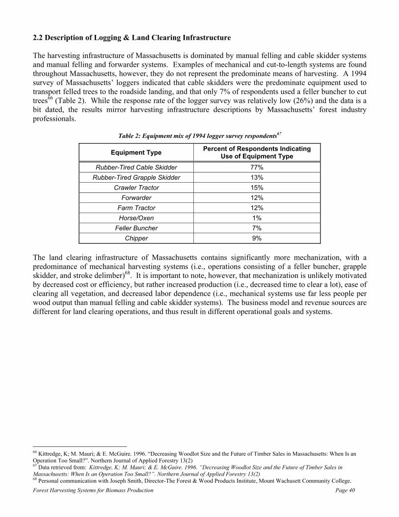
2.2 Description of Logging & Land Clearing Infrastructure The harvesting infrastructure of Massachusetts is dominated by manual felling and cable skidder systems and manual felling and forwarder systems. Examples of mechanical and cut-to-length systems are found throughout Massachusetts, however, they do not represent the predominate means of harvesting. A 1994 survey of Massachusetts’ loggers indicated that cable skidders were the predominate equipment used to transport felled trees to the roadside landing, and that only 7% of respondents used a feller buncher to cut trees66 (Table 2). While the response rate of the logger survey was relatively low (26%) and the data is a bit dated, the results mirror harvesting infrastructure descriptions by Massachusetts’ forest industry professionals.
Table 2: Equipment mix of 1994 logger survey respondents67
Equipment Type Percent of Respondents Indicating Use of Equipment Type
Rubber-Tired Cable Skidder 77% Rubber-Tired Grapple Skidder 13%
Crawler Tractor 15% Forwarder 12%
Farm Tractor 12% Horse/Oxen 1%
Feller Buncher 7% Chipper 9%
The land clearing infrastructure of Massachusetts contains significantly more mechanization, with a predominance of mechanical harvesting systems (i.e., operations consisting of a feller buncher, grapple skidder, and stroke delimber)68. It is important to note, however, that mechanization is unlikely motivated by decreased cost or efficiency, but rather increased production (i.e., decreased time to clear a lot), ease of clearing all vegetation, and decreased labor dependence (i.e., mechanical systems use far less people per wood output than manual felling and cable skidder systems). The business model and revenue sources are different for land clearing operations, and thus result in different operational goals and systems.
66 Kittredge, K; M. Mauri; & E. McGuire. 1996. “Decreasing Woodlot Size and the Future of Timber Sales in Massachusetts: When Is an Operation Too Small?”. Northern Journal of Applied Forestry 13(2) 67 Data retrieved from: Kittredge, K; M. Mauri; & E. McGuire. 1996. “Decreasing Woodlot Size and the Future of Timber Sales in Massachusetts: When Is an Operation Too Small?”. Northern Journal of Applied Forestry 13(2) 68 Personal communication with Joseph Smith, Director-The Forest & Wood Products Institute, Mount Wachusett Community College.

Forest Harvesting Systems for Biomass Production Page 41
2.3 Recommended Biomass Conversion Systems Often, biomass conversion systems are prevalent in certain regions because they are compatible with existing logging and land clearing infrastructures. This occurs because it is the fastest, easiest and least risky means for a contractor to add a biomass processing operation to their existing harvesting operations. Alternatively, one could establish a biomass conversion system relative to the characteristics of the region’s forest resources and harvesting activity (i.e., annual removals, average harvest block size, average harvesting intensity, distribution/density of harvest blocks, etc.). While far less common, this perspective theoretically would result in the most cost-effective and efficient approach to harvest roundwood and biomass; however establishing such a system potentially requires more investment (i.e., you have to purchase harvesting, processing, and transport equipment, opposed to establishing a system compatible with your existing harvesting equipment, which only requires you to purchase processing and transport equipment). Nonetheless, recommendations will be made relative to equipment and forest resource infrastructures. Recommendation Relative to Logging Infrastructure As indicated above, most cutting is done manually, and transport to the roadside landing is dominated by cable skidders and forwarders for harvesting activities. Conversion systems compatible with manual felling and cable skidders are listed in appendix A, and include system numbers 33 through 38 (Table 3). The processing and transport options listed in system number 34 are most complimentary to and offer the most flexibility (i.e., ability to efficiently process whole-trees and harvesting residue) with the manual felling and cable skidder system. Refer to the advantages and disadvantages discussion on pages 30 through 34 for additional information on processing and transportation components. It is also recommended to have the processing and transportation steps be accomplished by a firm external to the harvesting contractor because it is easier for the biomass conversion contractor to process material from multiple job sites in close proximity to one another. Refer to the advantages and disadvantages discussion on pages 35 and 36 for additional information on operational ownership distribution options.

Forest Harvesting Systems for Biomass Production Page 42
Table 3: Biomass Conversion Systems for Manual Felling & Cable Skidder Harvesting System
ID Harvesting Accumulation Processing Transportation
33 Manual Felling & Cable Skidder System Skip
Tub Grinder & Track-Type/Off-Road Loading
System
Tractor-Truck & Open Top Chip-Van
34 Manual Felling & Cable Skidder System Skip
Horizontal Grinder & Track-Type/Off-Road
Loading System
Tractor-Truck & Open Top Chip-Van
35 Manual Felling & Cable Skidder System Skip
Tub Grinder & Track-Type/Off-Road Loading
System
Roll-On/Off Transport Containers
36 Manual Felling & Cable Skidder System Skip
Horizontal Grinder & Track-Type/Off-Road
Loading System
Roll-On/Off Transport Containers
37 Manual Felling & Cable Skidder System Skip Off-Road Chipping
System Tractor-Truck & Open
Top Chip-Van
38 Manual Felling & Cable Skidder System Skip Off-Road Chipping
System Roll-On/Off Transport
Containers
Conversion systems compatible with manual felling and forwarders are listed in appendix A, and include system numbers 39 through 63. It is not recommended to utilize harvesting residue on jobs where forwarders are used because it is not cost-effective to accumulate or process (in the case of a mobile chipper) harvesting residue distributed throughout the block (see advantages and disadvantages discussion on pages 30-32)69. Recommendation Relative to Land Clearing Infrastructure Land clearing activities are predominately accomplished using the mechanical harvesting system. Conversion systems compatible with the mechanical system are listed in appendix A, and include system numbers 1 through 13 (Table 4). The processing and transport options listed in system number 3 are most complimentary to and offer the most flexibility (i.e., ability to efficiently process whole-trees and harvesting residue) with the mechanical system. Refer to the advantages and disadvantages discussion on pages 30 through 34 for additional information on the processing and transportation components. Whole-tree chippers are also a good processing option for the mechanical system because they produce a higher quality product than grinders, which receive a premium price at some wood-energy facilities. It is not the recommended choice though, because harvesting residue preparation is difficult (i.e., material must be relatively dirt and rock free and generally within reach of the road) and it has limited alternative uses (i.e., a grinder can be used to process mulch or grind and distribute land-clearing debris, whereas a non-paper quality chipper has far less alternative uses). 69 Pre-bunching material helps improve cost-effectiveness, but this is difficult to accomplish with manual felling.

Forest Harvesting Systems for Biomass Production Page 43
Table 4: Biomass Conversion Systems for Mechanical Harvesting System
ID Harvesting Accumulation Processing Transportation
1 Mechanical System Skip Tub Grinder & Track-
Type/Off-Road Loading System
Tractor-Truck & Open Top Chip-Van
2 Mechanical System Skip Tub Grinder & On-
Board or Road-Based Loading System
Tractor-Truck & Open Top Chip-Van
3 Mechanical System Skip Horizontal Grinder & Track-Type/Off-Road
Loading System
Tractor-Truck & Open Top Chip-Van
4 Mechanical System Skip Horizontal Grinder & On-Board or Road-
Based Loading System
Tractor-Truck & Open Top Chip-Van
5 Mechanical System Skip Tub Grinder & Track-
Type/Off-Road Loading System
Roll-On/Off Transport Containers
6 Mechanical System Skip Tub Grinder & On-
Board or Road-Based Loading System
Roll-On/Off Transport Containers
7 Mechanical System Skip Horizontal Grinder & Track-Type/Off-Road
Loading System
Roll-On/Off Transport Containers
8 Mechanical System Skip Horizontal Grinder & On-Board or Road-
Based Loading System
Roll-On/Off Transport Containers
9 Mechanical System Skip Whole-Tree Chipper &
On-Board or Road-Based Loading System
Tractor-Truck & Open Top Chip-Van
10 Mechanical System Skip Whole-Tree Chipper &
On-Board or Road-Based Loading System
Tractor-Truck & Enclosed Chip-Van
11 Mechanical System Skip Whole-Tree Chipper &
On-Board or Road-Based Loading System
Roll-On/Off Transport Containers
12 Mechanical System Skip Off-Road Chipping System
Tractor-Truck & Open Top Chip-Van
13 Mechanical System Skip Off-Road Chipping System
Roll-On/Off Transport Containers

Forest Harvesting Systems for Biomass Production Page 44
Moving Cost per Ton vs Harvest Volume (tons)
$0.00
$0.50
$1.00
$1.50
$2.00
$2.50
$3.00
$3.50
$4.00
0 500 1000 1500 2000 2500 3000 3500 4000 4500 5000 5500 6000 6500 7000 7500 8000
Harvest Volume (Tons)
Mov
ing
Cos
t per
Ton
Assumptions:Moving Time = 12hrsLowbed Cost per Hour = $70Fixed Moving Cost = $840
Recommendation Relative to Forest Resource Infrastructure The prevalence of manual felling and cable skidders/forwarder systems is not surprising relative to the forest resource infrastructure. As indicated above, the forest resource in Massachusetts consists of large [saw-timber quality] trees distributed amongst multiple landowners with small woodlots. Such an infrastructure requires frequent moves for high production systems which reduces machine utilization (i.e., downtime due to moving increases) and increases moving costs per unit (see Figure 39 for the relationship between moving cost for three machines and harvest volume per block). If moving time could be minimized through harvesting multiple blocks within close proximity to each other, the biomass conversion system number 3 would be the easiest and most economical means to harvest tree-length material and utilize harvesting residue for wood-energy. Scheduling multiple harvest blocks within the same area can be logistically difficult because of different landowner objectives, forest stand conditions, and terrain types, however, the clustered nature of harvesting activity suggests it is possible (Figure 38). Through working with landowner cooperatives, such as the Massachusetts Family Forests, or consulting foresters, stumpage sales and operations could be lumped together, thus reducing costs associated with moving and therefore enabling more productive and less labor intensive70 harvesting and biomass processing operations.
Figure 39: Relationship between moving costs and harvest volume per block
70 A manual felling and cable skidder system produces approximately 50 to 60 cords per person per week, whereas a mechanical system produces approximately 117 to 134 cords per person per week.

Forest Harvesting Systems for Biomass Production Page 45
A business plan is of utmost importance when pursuing any business venture or expansion. The business plan, at the very least, should include information on demand (e.g., wood energy facilities), resource supply (e.g., wood volume), competitors (e.g., other biomass processing companies), cost and revenue projections, and financing (e.g., sources of funds). Keep in mind that the value of the plan is more in the process of planning, rather than the product (e.g., a business plan sitting on the shelf). Be sure to test the sensitivity and understand the implications of all assumptions in your plan. Contractors with existing harvesting operations, should consider their capacity to support a biomass processing operation (see Production Balancing discussion below) as well as its strategic and logistical fit with existing equipment and business infrastructures (see Fit with Existing Operations discussion below). All companies considering establishment of a biomass processing operation should think about the implications of buying new or used equipment (see Used or New Equipment discussion below), as well as various risk management tactics to minimize the impact of loss if the wood-energy industry becomes uncompetitive (see Risk Management discussion below). 3.1 Production Balancing The amount of harvesting residue generated from a given site depends on species composition, merchantability specifications, and harvesting system. In general, hardwood harvests generate more harvesting residue than softwood harvests. Prentiss and Carlisle, a forest management company based in Maine, estimates processed harvesting residue volumes as 20% of the merchantable hardwood volume71. Results from a study in eastern Texas, suggest that harvesting residue volume, as a percent of merchantable volume, is approximately 23% for hardwood and 12% for softwood72. Nonetheless, estimates of 20%, 15% and 10% are sufficient for respective species compositions of hardwood, mixedwood, and softwood. Estimating the harvesting residue volume is important because it provides insight into the amount of biomass processing capacity that can be supported by a harvesting operation. For example, a logging contractor with four manual fellers and cable skidders, is capable of producing approximately 200 cords, or 500 tons, per week73. If the crew predominately operates in stands with hardwood removals, they would produce approximately 100 tons of harvesting residue or approximately 3 chip-van loads per week. Volumes of this scale would not match the production of a grinder or chipper, which produce anywhere from six to ten chip-van loads a day. Therefore, if a logging contractor of this scale purchased a grinder or chipper, they would be required to find additional processing work for the machine. Procuring additional processing work further complicates and increases the ambiguity of establishing a biomass processing operation.
71 Prentiss & Carlisle only processes the hardwood harvesting residue for wood-energy. The softwood harvesting residue is brought back into the woods to minimize impact on wet areas. 72 Data retrieved from: Bentley, James and Johnson, Tony. 2004. “Eastern Texas Harvest and Utilization Study”. USDA Forest Service – Southern Research Station. Resource Bulletin SRS-97. Total harvesting residue volumes multiplied by 75% to estimate harvesting residue attributed to tops and limbs. 75% percent estimate retrieved from: Mitchell, Dana. 2005. “Assessment of Current Technologies for Communition of Forest Residues” ASAE Paper No. 058024. American Society of Agricultural Engineers (ASAE) meeting paper. 73 50 cords per week per manual feller and cable skidder
Framework to Consider the Biomass Conversion Systems-Contractor’s Perspective

Forest Harvesting Systems for Biomass Production Page 46
3.2 Fit with Existing Operations As indicated by Figure 35 (page 30), not all harvesting and processing systems are compatible. Likewise, certain processing systems are not congruent with all transport options. Therefore, it is important for a logging contractor who is considering establishment of a biomass processing operation to understand which processing options work well with their existing harvesting operations. It is also wise to understand transport implications that processing equipment introduces. For example, it is difficult to achieve a full payload with a grinder and enclosed chip-van unless a fan/blower system is added to the grinder. This limits the pool of truck and trailer combinations capable of hauling from the grinder (i.e., if the contractor wants to subcontract transport activities) and the ability of the contractor to retrofit dry-vans (i.e., if the contractor wants to provide transport internally) (see Prentiss & Carlisle case study). Both of these scenarios could result in higher transport costs, thus reducing margins and/or the competitiveness of the contractor. This “thought process” is equally as important for companies without logging operations that are considering starting a biomass processing operation. Appendix A is a useful tool for analyzing the compatibility of different harvesting, processing, and transport options. In addition to the compatibility with equipment, companies should consider if the business venture is complimentary to existing business operations and infrastructure. For example, biomass processing operations typically produce anywhere from six to ten loads per day, which equates to approximately 30 to 50 loads per week. Is the company’s administrative and office infrastructure capable of processing the paperwork (e.g., trip-tickets, scale slips, etc.) and handling the accounting (e.g., accounts payable and receivables), or would this endeavor require the company to hire additional office staff and/or purchase software? As another example, chippers and grinders require a lot of preventative and other maintenance, some of which can be performed in the field, others which require a garage. Does the company have a sufficient garage, and if so, is it centrally located relative to where the machine will be operating? Is there a company-wide mechanic or mechanically inclined operator, or will repairs be performed by an external company or the original equipment manufacturer (OEM)? In some cases, relying on external mechanical services can be costly and increase downtime associated with repairs. The bottom line is that is more expensive for a company without [complimentary] infrastructure to establish a biomass processing operation, than it is for a company that can increase utilization of existing infrastructure. 3.3 New or Used Equipment The decision to purchase new or used equipment involves trade offs between ownership expenses (e.g., loan payments, insurance, etc.), machine utilization and maintenance and repair costs. The purchase price of used equipment is below that of new equipment, and therefore results in lower financial risk and increased ease of obtaining financing. Used equipment incurs greater mechanical breakdowns which decreases machine utilization and increases maintenance and repair costs. The volatility of costs associated with maintenance and repair for used equipment is greater than that of the ownership expenses for new equipment, thus making cash-flow forecasting and planning more difficult for operations with used equipment. Reduced machine availability can also influence the effectiveness of a chip or hog fuel supplier to an energy facility.

Forest Harvesting Systems for Biomass Production Page 47
3.4 Risk Management Risk, by definition, is the chance of loss. Loss associated with a biomass processing operation could be attributed to loss of market (i.e., in the scenario that wood-energy is not cost competitive amongst other energy sources), or a prolonged period of negative or minimal profit margins (i.e., in the scenario that the price of chips or hog fuel is at a price less than or slightly greater than costs). In either case, the concern is that the contractor would not be generating enough revenue to cover costs, which would result in loan default (i.e., credit risk) or unacceptable return on capital (i.e., shareholder risk). There are three general ways to reduce credit and shareholder risk associated with acquisition of biomass processing equipment: (1) leasing equipment; (2) contract terms; and (3) purchasing equipment with alternative uses. It is important to note though that risk management activities often reduce expected return. The first option, leasing the equipment does not require the contractor to make an investment in equipment. In the worst case scenario, where the demand for wood-energy material disappears, the contractor is left to pay a premature lease termination penalty74. Leasing equipment is more expensive than purchasing equipment, so profit margins are potentially reduced. The second option utilizes contract terms, such as take-or-pay clauses, long-term supply contracts, or repurchase agreements, to reduce the risk of lost demand. Such contract terms shift risk to the energy facility or forest management company (in the case of service contracts), and thus would have to be coupled with reduced pay rates (which equates to slimmer margins for the contractor) for the material. It is important to note that all contractual approaches to reduce risk should be reviewed and approved by the contractor’s legal counsel. The third option, purchasing equipment with alternative uses (i.e., an excavator can be used for road-building or construction activities; a grinder can be used to process mulch, etc.) offers other revenue generating options and therefore decreases the dependence on the competitiveness of the wood-energy industry.
74 It is important to make sure that the lease agreement offers the option to prematurely terminate the lease, and that all associated penalties are well understood.

Forest Harvesting Systems for Biomass Production Page 48
There are four general ways in which Massachusetts’ public sector can promote and support existing and new biomass conversion operations:
1. Promote a healthy and stable wood-energy industry. 2. Lower ownership costs through interest rate reductions. 3. Establish a cost share program to reduce start-up costs for companies establishing biomass
processing operations. 4. Facilitate knowledge transfer and other education related activities
4.1 Promote a Healthy & Stable Wood-Energy Industry The existence of a healthy and stable wood-energy industry in the state and region is essential to the promotion and support of biomass conversion operations. Without stable demand for raw material from processing facilities, few contractors will invest the time and capital required. Massachusetts’ can continue to promote the wood-energy industry by supporting state and federal legislation and other initiatives aimed at reducing economic disparity between renewable and non-renewable energy generation (e.g., a robust renewable portfolio standard, pre-purchase of renewable energy certificates from biomass generating facilities, etc.), establishing emission cap and trade systems, and/or altering the cost structure of wood or other sources of energy generation to benefit wood (i.e., income, sales, use, or property tax incentives/disincentives). 4.2 Lower Ownership Costs through Interest Rate Reductions Financial incentives can be extremely effective in affecting behavior and business activities. A recent report by the U.S. Government Accountability Office (GAO) indicated that financial incentives were a primary factor facilitating use of woody biomass for energy75. While GAO’s report focused on wood-energy facilities, similar risks (at a lesser scale though) and market volatility are faced by biomass conversion operations. Thus, it is a safe assumption that financial incentives could also promote the establishment of biomass conversion operations in Massachusetts and elsewhere. Massachusetts’ public sector can reduce ownership costs for contractors by offering reduced interest rate loans on biomass processing equipment. Reductions in interest rates can have significant savings over the term of a loan. For example, a 2% interest rate reduction can save approximately $23,000 over the term of a $400,000 loan (Figure 40). Importantly, interest rate reductions can be funded by the public sector without incurring loan risk or servicing. Using an approached adopted by The Maine Forest Service (MFS) to encourage use of best management practices, private lenders can offer interest rate reductions on loans for qualifying equipment by receiving a discount on funds provided by the public sector. In the MFS program, the Maine Municipal Bond Bank (MMB) buys a certificate of deposit (CD) equal to the
75 GAO. 2006. “Key Factors in Woody Biomass Utilization”. U.S. Government Accountability Office. GAO-06-336. Retrieved from: http://www.gao.gov/new.items/d06336.pdf
Role of Public Sector in Promoting & Supporting Biomass Conversion Operations

Forest Harvesting Systems for Biomass Production Page 49
face-value and term of the loan, and at an interest rate 2% below the current market rate. The lender calculates the reduction in cost of funds and applies it to the equipment loan, thereby reducing the interest expense for the contractor. Details of this program are available on the Maine Forest Service’s website76.
Figure 40: Calculation of savings from a 2% interest rate reduction
Base Scenario
Loan Amount = $400,000 Loan Term = 5 years
Annual Interest Rate = 9% (WSJ Prime rate plus 75 basis points) Monthly payments and compounding
Monthly Payment = $8303 [$8303.34 = $400000 * (((0.09/12)*(1+(0.09/12))^60)/((1+(0.09/12))^60)-1))]
Total Interest Paid = $98,200 [$98,200.4 = ($8303.34 * 60) - $400000]
2% Interest Rate Reduction
Loan Amount = $400,000 Loan Term = 5 years
Annual Interest Rate = 7% Monthly payments and compounding
Monthly Payment = $7,920 [$7920.48 = $400000 * (((0.07/12)*(1+(0.07/12))^60)/((1+(0.07/12))^60)-1))]
Total Interest Paid = $75,229 [$75,228.80 = ($7920.48 * 60) - $400000] 4.3 Establish a Cost Share Program to Reduce Start-Up Costs There are a variety of planning and administrative aspects to establishing a biomass processing operation, including creating a business plan, recruiting operators, creating and reviewing contracts, and many others. While essential to the successful implementation of any operation, these activities require time and money, which can cause them to be done in an unjustly fashion or avoided all together. A 2005 survey of logging contractors in Western Maine indicated that only 24% of the 40 companies surveyed had a formal business plan77. Providing money to partial fund these activities reduces the cost and time (if consultants are used) of the activities, and therefore increases the probability of their occurrence. As indicated in section three, a well thought-through and researched business plan is critical to the success of any business venture. In addition to determining whether or not the venture is feasible, it provides the business owner with an implementation plan and important [financial and other] metrics to monitor. Many companies in the logging industry do not perform sophisticated cost analyses to determine whether or not product pay rates are sufficient to earn an acceptable return on capital78. However, the process of comparing forecasted to actual results is valuable in determining and understanding causes of deviation, and in some cases has been linked to increased performance79. The point is that partial funding for
76 http://www.maine.gov/doc/mfs/fpm/water/direct_link_loan/mechanics.html 77 WMFRTC. 2006. “Business Visitation Program (BVP) Major Findings Report”. Western Maine Forest Resource Training Consortium (WMFRTC). Developed in cooperation with the Maine Department of Labor, Bureau of Employment Services. 78 Shaffer, R.M. 1986. “Structure for Determining Logging Contract Rates in the Southern United States”. In: Proceedings of Harvesting Machines and Systems Evaluation Workshop. Charleston, S.C. November 19-19, 1986. W.B. Stuart, Ed. 79 Ackoff, Russell. 1978. The Art of Problem Solving. John Wiley & Sons, Inc. New York, N.Y.

Forest Harvesting Systems for Biomass Production Page 50
business plans will increase their use and chance of good performance, thereby providing the industry with examples of successful businesses. It is difficult to encourage businesses to establish a biomass processing operation unless it can be proven that there is a viable market (i.e., the presence of a stable and healthy wood-energy industry (see recommendation above)) and a feasible business model. Business plans are also commonly required to receive financing from a lender. Hiring and retaining good employees is vital to the success of any business. Forest-based operations are particularly in need of top-quality operators because the “work-place” is often in a rural environment with limited cell-phone service and supervision. Further, operator skill has a large impact on production and costs; some estimate that operator skill explains 30 to 40% of the variation in production. The bottom line is that a successful biomass processing operation relies on having good employees. Finding good operators is time intensive though and can require advertising and other expenses. Finally, there are a variety of other administrative activities that are required to start a successful biomass processing operation. One of these activities is legal expenses associated with creating and reviewing contracts with customers and subcontractors. Too often, logging companies do not retain their own legal counsel for advice on these matters and this can be devastating in certain circumstances. Providing funds to cost share legal expenses would reinforce their importance and reduce the cost of the services. Cost sharing the funding of these start-up activities is essential to the value and likelihood of them happening. Engaging in these activities increases the probability of a contractor establishing and maintaining a successful biomass processing operation. The public sector should not provide full funding for these activities because the contractor is unlikely to participate adequately and/or use the outcomes of the endeavors unless they are required to invest time and money in their creation. 4.4 Facilitate Knowledge Transfer & Other Education Related Activities Massachusetts’ public sector can also provide funding and/or other support for the creation and distribution of workshops, technical writings, and equipment demonstrations. Of particular value would be technical bulletins and workshops on chip or hog-fuel product quality/specifications and grinder/chipper maintenance and repair. The Forest Resources Associations’ (FRA) northeastern division and the Certified Logging Professionals (CLP) of Maine facilitate an annual equipment maintenance roundtable in Maine and New Hampshire. The day-long event includes technical presentations by equipment manufacturers and open-forum discussions where contractors can share problems and solutions. The FRA/CLP roundtable has been extremely successful, often drawing an attendance greater than 100 people. A similar event, focused on grinder and chipper maintenance, could be offered in Massachusetts. Educational endeavors should be co-sponsored or channeled through the Forest and Wood Products Institute at Mount Wachusett Community College because they are already connected and offer educational services to the Massachusetts’ logging community. Some contractors have also indicated that equipment demonstrations for harvesting residue accumulation, processing, and transport functions would be valuable. There is a great deal of existing and emerging technology dealing with biomass processing, and it is often difficult to stay current with new technologies. A multiple-day event showcasing the available technology would allow contractors to be exposed to this technology in an efficient and time-effective manner. Such an event could be coupled with the Northeastern Loggers’ Annual Equipment Expo, which is occasional held in Springfield, MA, however, the nearest date that the expo could be in Springfield is 2010.

Forest Harvesting Systems for Biomass Production Page 51
ID Harvesting Accumulation Processing Transportation
1 Mechanical System Skip Tub Grinder & Track-
Type/Off-Road Loading System
Tractor-Truck & Open Top Chip-Van
2 Mechanical System Skip Tub Grinder & On-
Board or Road-Based Loading System
Tractor-Truck & Open Top Chip-Van
3 Mechanical System Skip Horizontal Grinder & Track-Type/Off-Road
Loading System
Tractor-Truck & Open Top Chip-Van
4 Mechanical System Skip Horizontal Grinder & On-Board or Road-
Based Loading System
Tractor-Truck & Open Top Chip-Van
5 Mechanical System Skip Tub Grinder & Track-
Type/Off-Road Loading System
Roll-On/Off Transport Containers
6 Mechanical System Skip Tub Grinder & On-
Board or Road-Based Loading System
Roll-On/Off Transport Containers
7 Mechanical System Skip Horizontal Grinder & Track-Type/Off-Road
Loading System
Roll-On/Off Transport Containers
8 Mechanical System Skip Horizontal Grinder & On-Board or Road-
Based Loading System
Roll-On/Off Transport Containers
9 Mechanical System Skip Whole-Tree Chipper &
On-Board or Road-Based Loading System
Tractor-Truck & Open Top Chip-Van
10 Mechanical System Skip Whole-Tree Chipper &
On-Board or Road-Based Loading System
Tractor-Truck & Enclosed Chip-Van
11 Mechanical System Skip Whole-Tree Chipper &
On-Board or Road-Based Loading System
Roll-On/Off Transport Containers
12 Mechanical System Skip Off-Road Chipping System
Tractor-Truck & Open Top Chip-Van
13 Mechanical System Skip Off-Road Chipping System
Roll-On/Off Transport Containers
14 Non-Traditional Mechanical System Skip
Tub Grinder & Track-Type/Off-Road Loading
System
Tractor-Truck & Open Top Chip-Van

Forest Harvesting Systems for Biomass Production Page 52
ID Harvesting Accumulation Processing Transportation
15 Non-Traditional Mechanical System Skip
Tub Grinder & On-Board or Road-Based
Loading System
Tractor-Truck & Open Top Chip-Van
16 Non-Traditional Mechanical System Skip
Horizontal Grinder & Track-Type/Off-Road
Loading System
Tractor-Truck & Open Top Chip-Van
17 Non-Traditional Mechanical System Skip
Horizontal Grinder & On-Board or Road-
Based Loading System
Tractor-Truck & Open Top Chip-Van
18 Non-Traditional Mechanical System Skip
Tub Grinder & Track-Type/Off-Road Loading
System
Roll-On/Off Transport Containers
19 Non-Traditional Mechanical System Skip
Tub Grinder & On-Board or Road-Based
Loading System
Roll-On/Off Transport Containers
20 Non-Traditional Mechanical System Skip
Horizontal Grinder & Track-Type/Off-Road
Loading System
Roll-On/Off Transport Containers
21 Non-Traditional Mechanical System Skip
Horizontal Grinder & On-Board or Road-
Based Loading System
Roll-On/Off Transport Containers
22 Non-Traditional Mechanical System Skip
Whole-Tree Chipper & On-Board or Road-
Based Loading System
Tractor-Truck & Open Top Chip-Van
23 Non-Traditional Mechanical System Skip
Whole-Tree Chipper & On-Board or Road-
Based Loading System
Tractor-Truck & Enclosed Chip-Van
24 Non-Traditional Mechanical System Skip
Whole-Tree Chipper & On-Board or Road-
Based Loading System
Roll-On/Off Transport Containers
25 Non-Traditional Mechanical System Skip Off-Road Chipping
System Tractor-Truck & Open
Top Chip-Van
26 Non-Traditional Mechanical System Skip Off-Road Chipping
System Roll-On/Off Transport
Containers
27 Mechanical Felling & Cable Skidder System Skip
Tub Grinder & Track-Type/Off-Road Loading
System
Tractor-Truck & Open Top Chip-Van
28 Mechanical Felling & Cable Skidder System Skip
Horizontal Grinder & Track-Type/Off-Road
Loading System
Tractor-Truck & Open Top Chip-Van
29 Mechanical Felling & Cable Skidder System Skip
Tub Grinder & Track-Type/Off-Road Loading
System
Roll-On/Off Transport Containers
30 Mechanical Felling & Cable Skidder System Skip
Horizontal Grinder & Track-Type/Off-Road
Loading System
Roll-On/Off Transport Containers

Forest Harvesting Systems for Biomass Production Page 53
ID Harvesting Accumulation Processing Transportation
31 Mechanical Felling & Cable Skidder System Skip Off-Road Chipping
System Tractor-Truck & Open
Top Chip-Van
32 Mechanical Felling & Cable Skidder System Skip Off-Road Chipping
System Roll-On/Off Transport
Containers
33 Manual Felling & Cable Skidder System Skip
Tub Grinder & Track-Type/Off-Road Loading
System
Tractor-Truck & Open Top Chip-Van
34 Manual Felling & Cable Skidder System Skip
Horizontal Grinder & Track-Type/Off-Road
Loading System
Tractor-Truck & Open Top Chip-Van
35 Manual Felling & Cable Skidder System Skip
Tub Grinder & Track-Type/Off-Road Loading
System
Roll-On/Off Transport Containers
36 Manual Felling & Cable Skidder System Skip
Horizontal Grinder & Track-Type/Off-Road
Loading System
Roll-On/Off Transport Containers
37 Manual Felling & Cable Skidder System Skip Off-Road Chipping
System Tractor-Truck & Open
Top Chip-Van
38 Manual Felling & Cable Skidder System Skip Off-Road Chipping
System Roll-On/Off Transport
Containers
39 Manual Felling & Forwarder System Bundler & Forwarder
Tub Grinder & Track-Type/Off-Road Loading
System
Tractor-Truck & Open Top Chip-Van
40 Manual Felling & Forwarder System Bundler & Forwarder
Tub Grinder & On-Board or Road-Based
Loading System
Tractor-Truck & Open Top Chip-Van
41 Manual Felling & Forwarder System Bundler & Forwarder
Horizontal Grinder & Track-Type/Off-Road
Loading System
Tractor-Truck & Open Top Chip-Van
42 Manual Felling & Forwarder System Bundler & Forwarder
Horizontal Grinder & On-Board or Road-
Based Loading System
Tractor-Truck & Open Top Chip-Van
43 Manual Felling & Forwarder System Bundler & Forwarder
Horizontal Grinder & Track-Type/Off-Road
Loading System
Roll-On/Off Transport Containers
44 Manual Felling & Forwarder System Bundler & Forwarder
Horizontal Grinder & On-Board or Road-
Based Loading System
Roll-On/Off Transport Containers
45 Manual Felling & Forwarder System Bundler & Forwarder
Tub Grinder & Track-Type/Off-Road Loading
System
Roll-On/Off Transport Containers
46 Manual Felling & Forwarder System Bundler & Forwarder
Tub Grinder & On-Board or Road-Based
Loading System
Roll-On/Off Transport Containers

Forest Harvesting Systems for Biomass Production Page 54
ID Harvesting Accumulation Processing Transportation
47 Manual Felling & Forwarder System Bundler & Forwarder
Whole-Tree Chipper & On-Board or Road-
Based Loading System
Tractor-Truck & Open Top Chip-Van
48 Manual Felling & Forwarder System Bundler & Forwarder
Whole-Tree Chipper & On-Board or Road-
Based Loading System
Tractor-Truck & Enclosed Chip-Van
49 Manual Felling & Forwarder System Bundler & Forwarder
Whole-Tree Chipper & On-Board or Road-
Based Loading System
Roll-On/Off Transport Containers
50 Manual Felling & Forwarder System Forwarder
Tub Grinder & Track-Type/Off-Road Loading
System
Tractor-Truck & Open Top Chip-Van
51 Manual Felling & Forwarder System Forwarder
Tub Grinder & On-Board or Road-Based
Loading System
Tractor-Truck & Open Top Chip-Van
52 Manual Felling & Forwarder System Forwarder
Horizontal Grinder & Track-Type/Off-Road
Loading System
Tractor-Truck & Open Top Chip-Van
53 Manual Felling & Forwarder System Forwarder
Horizontal Grinder & On-Board or Road-
Based Loading System
Tractor-Truck & Open Top Chip-Van
54 Manual Felling & Forwarder System Forwarder
Tub Grinder & Track-Type/Off-Road Loading
System
Roll-On/Off Transport Containers
55 Manual Felling & Forwarder System Forwarder
Tub Grinder & On-Board or Road-Based
Loading System
Roll-On/Off Transport Containers
56 Manual Felling & Forwarder System Forwarder
Horizontal Grinder & Track-Type/Off-Road
Loading System
Roll-On/Off Transport Containers
57 Manual Felling & Forwarder System Forwarder
Horizontal Grinder & On-Board or Road-
Based Loading System
Roll-On/Off Transport Containers
58 Manual Felling & Forwarder System Forwarder
Whole-Tree Chipper & On-Board or Road-
Based Loading System
Tractor-Truck & Open Top Chip-Van
59 Manual Felling & Forwarder System Forwarder
Whole-Tree Chipper & On-Board or Road-
Based Loading System
Tractor-Truck & Enclosed Chip-Van
60 Manual Felling & Forwarder System Forwarder
Whole-Tree Chipper & On-Board or Road-
Based Loading System
Roll-On/Off Transport Containers
61 Manual Felling & Forwarder System Bundler & Forwarder Skip Tractor-Truck & Log
Trailer
62 Manual Felling & Forwarder System Skip Off-Road Chipping
System Tractor-Truck & Open
Top Chip-Van

Forest Harvesting Systems for Biomass Production Page 55
ID Harvesting Accumulation Processing Transportation
63 Manual Felling & Forwarder System Skip Off-Road Chipping
System Roll-On/Off Transport
Containers
64 Manual Felling, Cable
Skidder, & Pull-Through Delimber System
Skip Tub Grinder & Track-
Type/Off-Road Loading System
Tractor-Truck & Open Top Chip-Van
65 Manual Felling, Cable
Skidder, & Pull-Through Delimber System
Skip Tub Grinder & On-
Board or Road-Based Loading System
Tractor-Truck & Open Top Chip-Van
66 Manual Felling, Cable
Skidder, & Pull-Through Delimber System
Skip Horizontal Grinder & Track-Type/Off-Road
Loading System
Tractor-Truck & Open Top Chip-Van
67 Manual Felling, Cable
Skidder, & Pull-Through Delimber System
Skip Horizontal Grinder & On-Board or Road-
Based Loading System
Tractor-Truck & Open Top Chip-Van
68 Manual Felling, Cable
Skidder, & Pull-Through Delimber System
Skip Tub Grinder & Track-
Type/Off-Road Loading System
Roll-On/Off Transport Containers
69 Manual Felling, Cable
Skidder, & Pull-Through Delimber System
Skip Tub Grinder & On-
Board or Road-Based Loading System
Roll-On/Off Transport Containers
70 Manual Felling, Cable
Skidder, & Pull-Through Delimber System
Skip Horizontal Grinder & Track-Type/Off-Road
Loading System
Roll-On/Off Transport Containers
71 Manual Felling, Cable
Skidder, & Pull-Through Delimber System
Skip Horizontal Grinder & On-Board or Road-
Based Loading System
Roll-On/Off Transport Containers
72 Manual Felling, Cable
Skidder, & Pull-Through Delimber System
Skip Whole-Tree Chipper &
On-Board or Road-Based Loading System
Tractor-Truck & Open Top Chip-Van
73 Manual Felling, Cable
Skidder, & Pull-Through Delimber System
Skip Whole-Tree Chipper &
On-Board or Road-Based Loading System
Tractor-Truck & Enclosed Chip-Van
74 Manual Felling, Cable
Skidder, & Pull-Through Delimber System
Skip Whole-Tree Chipper &
On-Board or Road-Based Loading System
Roll-On/Off Transport Containers
75 Manual Felling, Cable
Skidder, & Pull-Through Delimber System
Skip Off-Road Chipping System
Tractor-Truck & Open Top Chip-Van
76 Manual Felling, Cable
Skidder, & Pull-Through Delimber System
Skip Off-Road Chipping System
Roll-On/Off Transport Containers
77 Cut-to-Length System Bundler & Forwarder Tub Grinder & Track-
Type/Off-Road Loading System
Tractor-Truck & Open Top Chip-Van
78 Cut-to-Length System Bundler & Forwarder Tub Grinder & On-
Board or Road-Based Loading System
Tractor-Truck & Open Top Chip-Van

Forest Harvesting Systems for Biomass Production Page 56
ID Harvesting Accumulation Processing Transportation
79 Cut-to-Length System Bundler & Forwarder Horizontal Grinder & Track-Type/Off-Road
Loading System
Tractor-Truck & Open Top Chip-Van
80 Cut-to-Length System Bundler & Forwarder Horizontal Grinder & On-Board or Road-
Based Loading System
Tractor-Truck & Open Top Chip-Van
81 Cut-to-Length System Bundler & Forwarder Horizontal Grinder & Track-Type/Off-Road
Loading System
Roll-On/Off Transport Containers
82 Cut-to-Length System Bundler & Forwarder Horizontal Grinder & On-Board or Road-
Based Loading System
Roll-On/Off Transport Containers
83 Cut-to-Length System Bundler & Forwarder Tub Grinder & Track-
Type/Off-Road Loading System
Roll-On/Off Transport Containers
84 Cut-to-Length System Bundler & Forwarder Tub Grinder & On-
Board or Road-Based Loading System
Roll-On/Off Transport Containers
85 Cut-to-Length System Bundler & Forwarder Whole-Tree Chipper &
On-Board or Road-Based Loading System
Tractor-Truck & Open Top Chip-Van
86 Cut-to-Length System Bundler & Forwarder Whole-Tree Chipper &
On-Board or Road-Based Loading System
Tractor-Truck & Enclosed Chip-Van
87 Cut-to-Length System Bundler & Forwarder Whole-Tree Chipper &
On-Board or Road-Based Loading System
Roll-On/Off Transport Containers
88 Cut-to-Length System Forwarder Tub Grinder & Track-
Type/Off-Road Loading System
Tractor-Truck & Open Top Chip-Van
89 Cut-to-Length System Forwarder Tub Grinder & On-
Board or Road-Based Loading System
Tractor-Truck & Open Top Chip-Van
90 Cut-to-Length System Forwarder Horizontal Grinder & Track-Type/Off-Road
Loading System
Tractor-Truck & Open Top Chip-Van
91 Cut-to-Length System Forwarder Horizontal Grinder & On-Board or Road-
Based Loading System
Tractor-Truck & Open Top Chip-Van
92 Cut-to-Length System Forwarder Tub Grinder & Track-
Type/Off-Road Loading System
Roll-On/Off Transport Containers
93 Cut-to-Length System Forwarder Tub Grinder & On-
Board or Road-Based Loading System
Roll-On/Off Transport Containers
94 Cut-to-Length System Forwarder Horizontal Grinder & Track-Type/Off-Road
Loading System
Roll-On/Off Transport Containers

Forest Harvesting Systems for Biomass Production Page 57
ID Harvesting Accumulation Processing Transportation
95 Cut-to-Length System Forwarder Whole-Tree Chipper &
On-Board or Road-Based Loading System
Tractor-Truck & Open Top Chip-Van
96 Cut-to-Length System Forwarder Whole-Tree Chipper &
On-Board or Road-Based Loading System
Tractor-Truck & Enclosed Chip-Van
97 Cut-to-Length System Forwarder Whole-Tree Chipper &
On-Board or Road-Based Loading System
Roll-On/Off Transport Containers
98 Cut-to-Length System Forwarder Horizontal Grinder & On-Board or Road-
Based Loading System
Roll-On/Off Transport Containers
99 Cut-to-Length System Bundler & Forwarder Skip Tractor-Truck & Log Trailer
100 Cut-to-Length System Skip Off-Road Chipping System
Tractor-Truck & Open Top Chip-Van
101 Cut-to-Length System Skip Off-Road Chipping System
Roll-On/Off Transport Containers

Forest Harvesting Systems for Biomass Production Page 58
Harvesting Residue
Tree Length
Whole-Trees
Stroke Delimber Forest Road
Harvesting Residue
Tree Length
Whole-Trees
Stroke Delimber Forest Road
Company Description JML Trucking & Excavating is a construction company located in Errol, NH. The company’s primary work is road building and other heavy construction, however, it also operates a wood-grinding operation on land managed by Wagner Forest Management. JML Trucking & Excavating started the operation approximately two years ago when Wagner Forest Management approached them with the idea. They are pleased with the arrangement and would consider establishing another wood-grinding operation Harvesting The wood-grinding operation primarily utilizes harvesting residue (e.g., tops & branches), however, occasionally small and cull trees are utilized. Job sites are harvested with a mechanical system (i.e., operations consisting of a feller buncher, grapple skidder, and stroke delimber) by a third-party contracted through Wagner Forest Management. In a mechanical harvesting system, trees are cut by a feller buncher and brought in whole-tree form to the roadside landing by a grapple skidder. The stroke delimber, which is located on the landing, removes the branches and tops the tree based on merchantable diameter specifications. The stroke delimber moves the branches and tops to the landing on the other side of the road and places the tree-length material to the side to be further merchandized (Figure 1). Between cycles, the grapple skidder pushes the harvesting residue to the back of the landing to decrease the height of the brush pile.
Figure 1: Material management at the landing during the harvest
JML Trucking & Excavating Case Study (Appendix B)

Forest Harvesting Systems for Biomass Production Page 59
The tree-length material is processed into various products (e.g., pulpwood, palletwood, bolt logs, sawlogs, etc.) and transported to processing facilities. The wood-grinding operation moves to the job between six months to a year after the harvest and processes the brush piles (Figure 2).
Figure 2: One year old brush pile Grinding The brush piles are processed into smaller material by a 525 horsepower Morbark horizontal grinder. The grinder is fed harvesting residue by an excavator with a thumb-attachment (Figure 3). The grinder does not need a separate operator. Processed material is either loaded directly into a chip-van (Figure 4) or piled on the ground and later loaded by an excavator (Figure 5). JML Trucking & Excavating indicated that it is more efficient to load the chip-van directly, but pile loading is often necessary due to frequent mechanical breakdowns of the grinder. The grinder is transported to the garage about twice a week for repairs or regular maintenance. The grinder operator indicated that there are over 100 grease fittings on the machine and that ideally it could use one to two hours of preventative maintenance per day. During the winter, a heater is left on the machine overnight to prevent the belt from freezing. The highest production rate the grinding operation has achieved was 300 tons a day. The theoretical maximum production of the grinder is 60 tons per hour80, however, this is rarely achieved because of moving time, unbalanced trucking capacity, delays due to accumulating brush, and mechanical breakdowns. The grinder consumes approximately 125 gallons of fuel per day and a production-based bonus system is in place for the operator. The grinder is transported between jobs by a tractor truck and within jobs by the excavator and a chain. JML Trucking & Excavating said they do not require a minimum volume (i.e., number of loads) to move to a job.
80 This is based on the average loading time (30 minutes) of the direct loading method and the average chip-van payload per trip (30 tons). 30 tons / 0.5 hours = 60 tons per hour

Forest Harvesting Systems for Biomass Production Page 60
Harvesting Residue
Forest Road
ExcavatorGrinder
Chip Truck
Harvesting Residue
Forest Road
ExcavatorGrinder
Chip Truck
Figure 3: Excavator feeding brush into the grinder
Figure 4: Direct Loading

Forest Harvesting Systems for Biomass Production Page 61
Harvesting Residue
Excavator
Forest Road
Excavator
Chip Truck
Grinder
Harvesting Residue
Excavator
Forest Road
Excavator
Chip Truck
Grinder
Figure 5: Pile Loading
Transportation The processed material is transported by chip-trucks to Boralex Energy located in Stratton, ME. The trip cycle from the operation is approximately three hours. Three to four chip trucks balance the production of the grinder at this haul distance/cycle time. Payloads varied from 28 to 30 tons depending upon the season. During the winter, chip-vans are swept clean and calcium is applied to the floors nightly to prevent the chips from freezing. Loading times at the job-site were 20 to 25 minutes for the pile-loading method and 30 minutes for the direct loading method. Chip-vans are unloaded at the energy facility by chip-van dumpers. JML Trucking & Excavating indicated that the costs of operating chip-trucks on forest roads is higher than the costs of operating log-trucks on forest roads because chip-vans are less durable than log-trailers.
Figure 6: Excavator loading a chip-truck

Forest Harvesting Systems for Biomass Production Page 62
Harvesting Residue
Tree Length
Whole-Trees
Stroke Delimber Forest Road
Harvesting Residue
Tree Length
Whole-Trees
Stroke Delimber Forest Road
Company Description Prentiss & Carlisle Co., Inc. is a forestry company headquartered in Bangor, ME. The company’s primary work is forest management, but it also operates company-owned harvesting crews. In the fall of 2005, Prentiss & Carlisle established a biomass processing operation. The operation processes harvesting residue (e.g., tops and branches) and occasionally small or cull trees on company-crew harvesting operations and low-grade material purchased at its concentration yard in Enfield, ME. Harvesting The job sites are harvested with a mechanical system (i.e., operations consisting of a feller buncher, grapple skidder, and stroke delimber) by Prentiss & Carlisle’s company-owned harvesting crews. In a mechanical harvesting system, trees are cut by a feller buncher and brought in whole-tree form to the roadside landing by a grapple skidder. The stroke delimber, which is located on the landing, removes the branches and tops the tree based on merchantable diameter specifications. The stroke delimber moves the branches and tops to the landing on the other side of the road and places the tree-length material to the side to be further merchandized (Figures 1, 2, and 3). The tree-length material is processed into various products (e.g., pulpwood, palletwood, bolt logs, sawlogs, etc.) and transported to processing facilities.
Figure 1: Material management at the landing during the harvest
Prentiss & Carlisle Co., Inc. Case Study (Appendix C)

Forest Harvesting Systems for Biomass Production Page 63
Figure 2: Stroke delimber moving harvesting residue from the tree-length side
of the landing to the harvesting residue side.81
Figure 3: Stroke delimber piling harvesting residue82
81 Picture provided by Prentiss & Carlisle. 82 Picture provided by Prentiss & Carlisle.

Forest Harvesting Systems for Biomass Production Page 64
Center of the road
30 feet
Center of the road
30 feet
The harvesting residue is processed by a chipper which is fed by a loader, therefore the center of the brush piles must be within 30 feet of the center of the road83 (Figure 4). This requires the harvesting residue to be placed towards the front of the landing, causing landing space to become a limiting factor of harvesting residue utilization. The tree-length to harvesting residue landing space occupancy ratio is often one to two, therefore the harvesting residue must be carried and placed elsewhere by the stroke delimber or returned to the woods84 once the harvesting residue side of the landing is full. This can also occur if harvesting residue is not processed and transported before the harvesting crew returns to the landing85. Typically, the chipper and loader move to the job site after the harvesting crew completes the job. Occasionally, they will arrive on the job while the harvesting is taking place if the harvesting crew needs to return to a landing that is occupied with tree-length and harvesting residue. The maximum time lapse between harvesting and chipping is one year because after one year the harvesting residue becomes too brittle to efficiently handle.
Figure 4: Maximum reach of loader
83 30 feet is the maximum reach of Prentiss & Carlisle’s loader. 84 Harvesting residue that returns to the woods is dispersed on the skid trails to minimize ground impact. 85 With a mechanical harvesting system, it is common to have multiple landings that are used more than once during the same harvest job.

Forest Harvesting Systems for Biomass Production Page 65
Chipping Brush piles are processed into chips by a 425 horsepower Morbark horizontal drum chipper. The chipper is fed harvesting residue by a loader mounted on a crane carrier (Figure 5). The chipper is controlled by a portable remote and therefore does not need a separate operator. Processed material is always loaded directly into a chip-van because the loader is not capable of re-handling chips (Figures 6 and 7). The chipper chute is often angled towards chip-van wall to achieve maximum payload (Figure 7). The loader loads log trucks with tree-length material between chip-van loads (Figure 8). The chipper has six knives. The frequency for which knives are changed is dependent on the type of wood being processed. If processing clean wood, the knives may only need to be changed once every two days. This can increase to three to four times a day if processing dirty wood or dense hardwood. It takes approximately 20 minutes to change knives. Knife sharpening is outsourced to an external company which picks up the dull knives at the garage and leaves sharp ones. The chipper requires approximately two to three hours of preventative maintenance per day, which includes regular greasing and cleaning of the machine. The chipper is cleaned between every load to reduce chance of fire and to allow the machine to cool down. Prentiss & Carlisle indicated that it was essential to always have a service truck with an air compressor86 on site with the chipper. On the day of the site visit, Prentiss & Carlisle had a borrowed chipper because their machine had been broken down for two weeks due to a computer malfunction.
Figure 5: Loader feeding trees into the chipper87
86 The air compressor is used to clean the machine between loads and to facilitate changing of chipper knives. 87 The chipper was operating at the concentration yard in Enfield, ME during the site visit.

Forest Harvesting Systems for Biomass Production Page 66
Tree Length
Forest Road
Harvesting Residue
Chip Truck
Chipper
Loader
Tree Length
Forest Road
Harvesting Residue
Chip Truck
ChipperChipper
Loader
Figure 6: Configuration of loader, chipper, & chip truck
Figure 7: Processing harvesting residue into chips on a forest landing

Forest Harvesting Systems for Biomass Production Page 67
Tree Length
Forest Road
Harvesting Residue
Log Truck
Loader
Chipper
Tree Length
Forest Road
Harvesting Residue
Log Truck
Loader
Chipper
Figure 8: Loading tree-length material between chip loads The chipping operation produces 372 tons per day88 if it is located at the concentration yard and 248 tons per day89 at the forest location. The difference in production is primarily due to increased trucking distance and limited trucking capacity from the forest locations. The theoretical maximum production of the chipper is 46 tons per hour90, however, this is rarely achieved because of moving time, unbalanced trucking capacity, type of material being processed (e.g., roundwood, brush, etc.), and mechanical breakdowns. The chipper consumes 0.33 gallons of fuel per ton of chips produced. The operator is paid hourly. The chipper is transported between and within jobs behind the crane body with a pintle hook and is detached once it arrives on site (Figures 6 and 7). The loader grabs the tongue of the chipper to move it around the landing. Prentiss & Carlisle requires a minimum volume of 375 tons (i.e., approximately 12 loads) before they will move the chipper to a job site. Harvesting residue volume is estimated on a job basis by multiplying the hardwood roundwood volume for the job by 20%.
88 This is based on 12 loads at the average chip-van payload (31 tons). 89 This is based on 8 loads at the average chip-van payload (31 tons). 90 This is based on the average loading time (40 minutes) and the average chip-van payload per trip (31 tons). 31 tons / 0.67 hours = 46 tons per hour

Forest Harvesting Systems for Biomass Production Page 68
Transportation Chips are transported by chip-trucks to Indeck Energy Services’ wood-energy facility located in West Enfield, ME. Two chip-vans and one tractor truck service the chipper when it is located at the concentration yard in Enfield, ME and two chip-vans and two tractor trucks service the chipper when it is located in the forest. When the chipper is at the concentration yard, the tractor truck picks up the loaded chip-van and leaves an empty chip-van (i.e., spotting trailers). Chip-vans are not spotted when the chipper is located in the forest. Prentiss & Carlisle owns two tractor trucks and three chip-vans. Truck drivers are paid hourly when they haul chips91. The chip-vans are retrofitted dry-vans. Retrofitting the vans included adding a third axle, replacing the doors, adding windows, and reinforcing the top of the van. Prentiss & Carlisle indicated that this method of acquisition was more labor intensive but significantly cheaper than buying new chip-vans. Further, the vans previously were used for inter-modal activities at the railroad, and thus were more rugged than typical dry-vans. The average payload is 31 tons, but this varies with wood moisture content. Prentiss & Carlisle indicated that is difficult for them to achieve a full payload with dry material. During the winter, calcium is applied to chip-vans between loads to prevent the chips from freezing. The average loading time is 40 minutes. Chip-vans are unloaded at the energy facility by chip-van dumpers.
91 The tractor trucks are used to haul log trailers when they are not hauling chip-vans. Truck Drivers are paid on a percent of load revenue basis when hauling log trailers.

Forest Harvesting Systems for Biomass Production Page 69
Company Description Dean Young Forestry is a logging and trucking company located in Franklin, ME. The company operates a cut-to-length harvesting system and road building operation on small woodlots throughout Downeast Maine. All jobs are contracted on a stumpage basis92. Dean Young Forestry added a chipping operation to the cut-to-length harvesting system in June of 2006. Harvesting The chipping operation primarily utilizes large tree tops and small or dead trees. Job sites are harvested with a modified cut-to-length system. The operation consists of a feller buncher, processor, and two forwarders. In this system, trees are cut by a feller buncher and placed into either a biomass pile (Figure 1) or a roundwood pile. Trees are placed into the roundwood pile if they meet the specifications for pulpwood93 or higher valued products. The processor follows behind the feller buncher and processes trees in the roundwood pile by removing the branches and sawing the tree into appropriate lengths (e.g., 8 feet, 12 feet, 16 feet, etc.). If a biomass pile is nearby or there will be enough volume generated by processing trees from a large roundwood pile, the processor places the tree tops in an existing biomass pile or in the latter case, creates a new biomass pile.
Figure 1: A biomass pile harvested by the feller buncher
92 Stumpage value refers to the value of a tree standing in the woods. It is a function of the price received at the mill for its various products (e.g., biomass, pulpwood, palletwood, bolt logs, sawlogs, etc.) minus all of the costs involved with getting it there (e.g., forestry expenses, road building, harvesting, processing, transporting, etc.). 93 Dean Young Forestry indicated that during the time of the site visit, pulpwood prices were so low that they were better off to process it as biomass rather than market it as pulpwood
Dean A. Young, Forestry Case Study (Appendix D)

Forest Harvesting Systems for Biomass Production Page 70
The forwarder moves the biomass piles from the forest to the roadside landing (Figure 2) and places them behind the chipper. Often the crane will unload the biomass from the forwarder to reduce unloading time, and therefore lower forwarder turn-times. The chipper and crane are usually on the job site while harvesting is taking place; otherwise the biomass is piled for later chipping. Biomass is only piled on the roadside landing if the chipper is broken down. Biomass piles are always processed into chips within two months of harvesting to minimize volume loss due to moisture content reduction. Forwarder payloads average 6.4 tons when moving material from the biomass piles94. Forwarder payloads for processed logs are typically 10 tons. Forwarders move processed logs from roundwood piles to the roadside landing if there is not a chip-van in front of the chipper. Processed logs are either placed along the road (Figure 3) or loaded directly onto a log trailer. Logs piled along the road are picked up and transported by a tractor truck and self-loading (center-mount) trailer. A cable skidder and manual feller are also commonly on the job site to cut and process trees that are too big for the feller buncher to harvest. The entire system is depicted in figure 4.
Figure 2: Forwarder moving biomass piles from the forest to the roadside landing
94 This is based on the average number of forwarder trips per load of chips (5) and the average payload (32 tons). 32 tons / 5 forwarder trips = 6.4 tons per forwarder trip
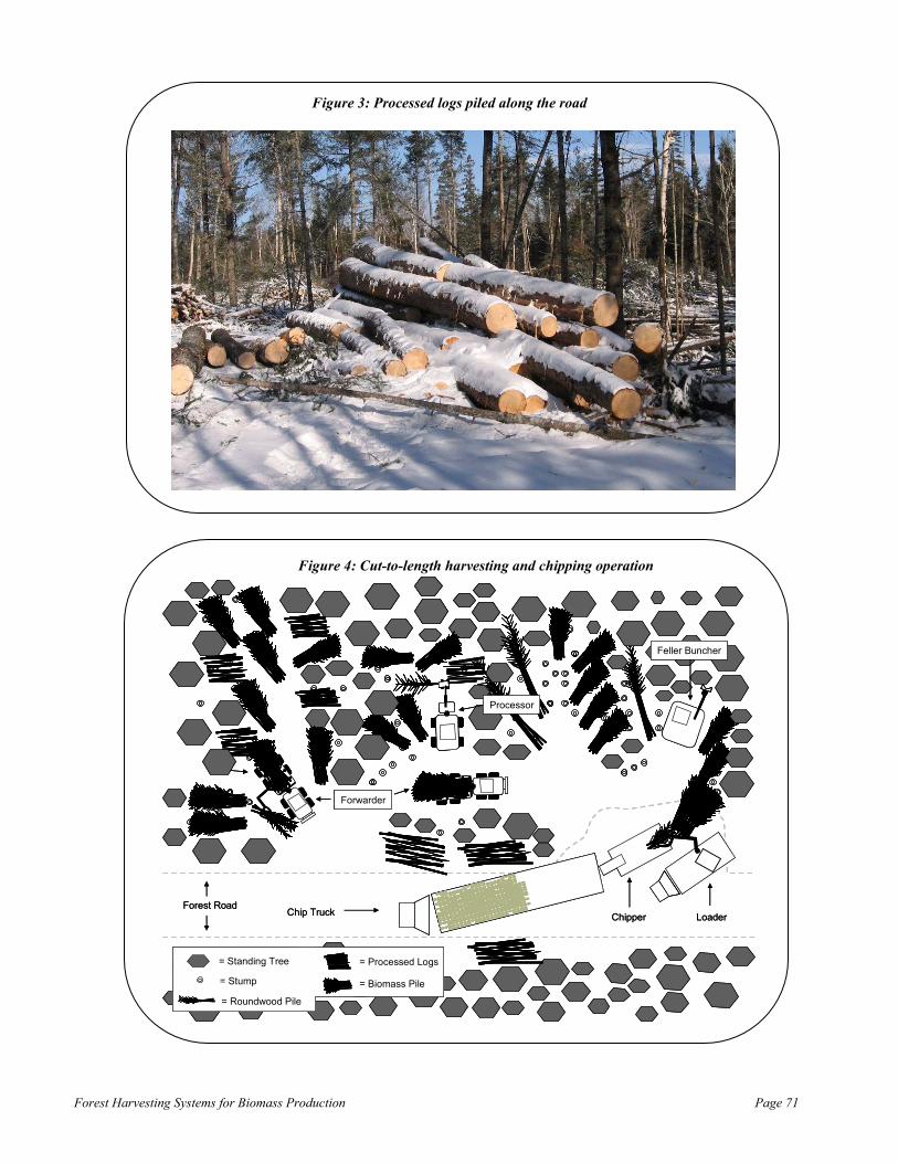
Forest Harvesting Systems for Biomass Production Page 71
Forest Road
Forwarder
Processor
Chip Truck
Feller Buncher
Chipper Loader
= Standing Tree
= Stump
= Roundwood Pile
= Processed Logs
= Biomass Pile
Forest Road
Forwarder
Processor
Chip Truck
Feller Buncher
Chipper Loader
= Standing Tree
= Stump
= Roundwood Pile
= Processed Logs
= Biomass Pile
Figure 3: Processed logs piled along the road
Figure 4: Cut-to-length harvesting and chipping operation

Forest Harvesting Systems for Biomass Production Page 72
Chipping Biomass piles are processed into chips by a 435 horsepower Morbark horizontal drum chipper, which is fed harvesting residue by a loader mounted on a crane carrier. The chipper is controlled by a portable remote and therefore does not need a separate operator. Processed material is always loaded directly into a chip-van because the loader is not capable of re-handling chips. The chipper and loader are idled if there is not a chip-van on the job site. The chipper has six knives. The frequency for which knives are changed is dependent on the season and the related dirtiness of the material. In the winter, when the material is relatively dirt free, knives are changed once every three days. This increases to once a day during mud season (i.e., spring) and in the summer, however. Knife sharpening is outsourced to an external company in Bangor, ME95. Dean Young Forestry is responsible for transporting knives to and from the knife sharpening company’s location. The chipper requires approximately one and a half hours of preventative maintenance per day, which includes regular greasing and cleaning. The chipper is cleaned between every load via an air compressor mounted on the chipper. Dean Young Forestry indicated that they have had tremendous mechanical problems with the chipper since they purchased it in June; including issues with belts, pumps, and the exhaust system. On the day of the site visit, the chipper had been broken down for one week due to a problem with the drum. The chipping operation produces approximately 19296 tons per day. The theoretical maximum production of the chipper is 48 tons per hour97, however, this is rarely achieved because of moving time, unbalanced trucking capacity and mechanical breakdowns. The chipper consumes eight to ten gallons per hour. The operator is paid hourly. The chipper can be transported between and within jobs by the crane body, dump truck, or tractor truck. Most often the chipper is moved between jobs by the dump truck, and within a job by the crane body or tractor truck. The chipper is moved behind the crane body via a pintle hook.
95 Bangor, ME is a one hour drive from Dean Young Forestry’s garage in Franklin, ME 96 This is based on 6 loads at the average payload (32 tons) 97 This is based on the average loading time (40 minutes) and the average chip-van payload per trip (32 tons). 32 tons / 0.67 hours = 48 tons per hour

Forest Harvesting Systems for Biomass Production Page 73
Transportation The chips are transported by chip-trucks to Indeck Energy Services’ wood-energy facility located in West Enfield, ME or Worcester Energy’s facility located in Deblois, ME. Two tractor trucks and four enclosed chip-vans transport the chips. Chip-vans are spotted on the job site, which means that the tractor truck picks up a loaded chip-van and leaves an empty chip-van. The empty chip-van is loaded while the tractor truck is in route to the energy facility. Idle time of the chipper and loader are kept to a minimum if the haul distance is kept within 40 to 50 miles. Each tractor truck picks up a loaded log trailer when it returns from the last chip-van load for the day. The empty chip-vans are kept on site to be loaded the next morning. The tractor truck goes home loaded and delivers the logs the next morning. When the tractor truck delivers the log load in the morning, it returns to the job site, leaves the log-trailer to be loaded by the forwarders during the day, and takes a loaded chip-van. During the winter, loaded chip-vans do not sit overnight because the load can freeze into the van and make it difficult to unload. Dean Young Forestry owns two tractor trucks and five chip-vans. The fifth chip-van is used as a spare or to balance trucking and chipping capacity at haul distances greater than 50 miles. The chip-vans were bought used. Truck drivers are paid hourly when hauling logs or chips. The average payload is 32 tons, but this varies with moisture content. During the winter, calcium is applied nightly to the chip-vans to prevent the chips from freezing. The average loading time is 40 minutes. Chip-vans are unloaded at the energy facilities by chip-van dumpers.

Forest Harvesting Systems for Biomass Production Page 74
Company Description Boralex is a renewable energy company that operates wood-residue thermal and hydroelectric power stations in North America, and wind farms in France. Boralex has eight wood-energy facilities, five of which are located in the State of Maine (Figure 1). The wood-energy facilities consume approximately three million tons of wood-residue per year. The Maine mills consume two-thirds of the annual wood volume. Approximately 60% of the volume comes from harvesting residue (e.g., tops and branches) processed on logging job sites. The mechanical system (i.e., operations consisting of a feller buncher, grapple skidder, and stroke delimber) is the most frequent harvesting approach used on jobs that it purchases material from. In 2005, Boralex started financing in-woods biomass processing equipment for their contractors. The financing program was established to create a greater sense of partnership with their contractors and to provide Boralex’s wood-energy facilities with consistent fuel deliveries at less volatile prices. Boralex is currently financing 21 machines; consisting of 2 grinders and 19 chippers.
Figure 1: Boralex’s wood-energy facilities located in the State of Maine
Boralex, Inc. Case Study (Appendix E)

Forest Harvesting Systems for Biomass Production Page 75
Financing Program The financing program is a “lease to buy” agreement, where payment is based on wood deliveries (i.e., $/ton). The program is available to any reputable contractor who is interested in establishing an in-woods biomass processing operation. Each agreement is tailored to meet the mutual needs of the contractor and Boralex. The agreements are governed by a contract that states the annual volume to be delivered to Boralex’s facilities and respective prices. The typical contract length is five years with an annual volume of approximately 50,000 to 60,000 tons98. The annual volume is expected to be delivered in a 40 week time period99. Volume obligations and delivered prices are renegotiated annually to provide flexibility for the contractor and Boralex. The contractor is responsible for negotiating the purchase price with the equipment dealer, and Boralex pays the invoice for the machine plus the cost of the manufacturer’s recommended parts inventory. Under the terms of the agreement, the contractor pays back the principal, and interest at 7.0%, through wood deliveries. The contractor is not required to make an equipment payment if they do not deliver wood. When a load of chips or hog fuel is delivered, a dollar per ton amount (e.g., $2.50/ton) is withheld from payment to the contractor and credited towards money owed on the machine (Table 1). With prior approval from Boralex, the contractor can use the equipment for deliveries to non-Boralex facilities, however, the contractor is required to make the same dollar per ton equipment payment to Boralex on the volume. The ownership title transfers to the contractor and payment withholding ceases when the money owed equals zero. Once the contractor owns the machine, they are still required to fulfill their annual volume obligation for the remaining term of the contract, but they do not need Boralex’s prior approval to make deliveries to non-Boralex facilities. The contractor has the option to forfeit the agreement prematurely, however, doing so eliminates all accrued ownership in the financed equipment. If the wood-energy industry becomes uncompetitive and all of Boralex’s wood-energy facilities close, a force majeure clause would be triggered, thus elevating the obligation for the contractor to continue to make equipment payments. In the occurrence of such an event, the contractor has the option to pay the remaining balance on the equipment liability, however, they are not required to.
98 This volume applies to large chippers or grinders. The typical annual volume obligation for a smaller chipper is 10,000 to 15,000 tons. 99 This equates to an average daily delivery of approximately eight to nine loads.

Forest Harvesting Systems for Biomass Production Page 76
Table 1: Example of cash flows associated with the delivery of chips or hog fuel to a Boralex facility
Load # Delivered Price per
Ton
Equipment Payment per Ton
Volume (Tons)
Total Revenue
Equipment Payment
Payment to
Contractor
Money Owed on
Equipment
$400,000
1 $30 $2.50 32.00 $960 $80 $880 $399,920
2 $30 $2.50 31.50 $945 $79 $866 $399,841
3 $30 $2.50 32.30 $969 $81 $888 $399,761
4 $30 $2.50 31.70 $951 $79 $872 $399,681
5 $30 $2.50 32.00 $960 $80 $880 $399,601
6 $30 $2.50 30.12 $904 $75 $828 $399,526
7 $30 $2.50 29.70 $891 $74 $817 $399,452
8 $30 $2.50 32.00 $960 $80 $880 $399,372
9 $30 $2.50 32.40 $972 $81 $891 $399,291
Operations The contractor is required to pay for inland marine insurance, and all operating costs (e.g., labor, maintenance and repair, fuel, etc.) associated with the financed machine. The contractor is also directly or indirectly (i.e., via subcontractors) responsible for the ownership and operating costs related to loading (e.g., excavator, loader on crane carrier, etc.), transport (e.g., tractor trucks, chip vans, etc.), and any support equipment/assets (e.g., pick-up truck, garage, etc.). Boralex pays a diesel fuel surcharge based on the prior month’s fuel price movement. The Energy Information Administration’s “weekly retail on-highway diesel price” data100 is used to determine the surcharge. Commonly, Boralex purchases the material FOB-shipping point101, and contracts the processing and transportation (i.e., the contractor provides a service). In other cases, the contractor purchases the material and sells the processed material to Boralex FOB-delivery point102 (i.e., the contractor sells a product). Conclusion Boralex indicated that while the program requires more oversight, communication, and financial risk than traditional means of procuring wood material, it sends a message to their contactors/suppliers that they think the wood-energy industry has a strong future and that they want a long-term relationship with them. Four contractors have already reused the program, thus indicating they are pleased with the arrangement.
100 http://tonto.eia.doe.gov/oog/info/wohdp/diesel_detail_report_combined.asp 101 FOB = Free On Board. Ownership title transfers at the forest roadside. Processing and transportation costs are the responsibility of Boralex and are thus not included in the purchase price. 102 Ownership title transfers at the wood-energy facility. Processing and transportation costs are the responsibility of the contractor and are included in the purchase price

Forest Harvesting Systems for Biomass Production Page 77
Several of their contractors have had frequent mechanical problems, thus causing the contractors to incur higher than anticipated downtime and costs. Boralex is currently investigating ways to pool the purchasing power of their contractors to increase the availability and decrease the costs of parts and mechanical service. Boralex also is thinking about establishing a bank account with each of the participating contractors, where a fixed dollar amount per ton (e.g., $0.25/ton) would be deposited into the account with each delivery. The money would be available to cover maintenance costs in the case of a premature lease forfeit, to finance payment advances, and/or to make periodic bonus payments to the contractor.

Forest Harvesting Systems for Biomass Production Page 78
Company Description Fort Mountain Companies (hereinafter referred to as Fort Mountain) is a compilation of three companies offering forest management, land-clearing, road-construction, harvesting, chipping, and transport services103. Fort Mountain is located in Allenstown, NH and established a chipping operation 10 years ago that only chips material from company-owned harvesting crews. Harvesting jobs are contracted on a stumpage basis104. Land-clearing jobs are also contracted on a stumpage-basis (if there is any merchantable timber), however, there is typically a net cost to the landowner. Fort Mountain determines the net cost for land-clearing jobs by calculating the total cost to achieve the landowner’s desired result, minus revenue generated from timber removals. Harvesting The chipping operation primarily utilizes tree tops and/or low-grade whole trees. Fort Mountain determines the [tree] product specification for chipping based on market prices for biomass chips and pulpwood. Jobs sites are harvested with a mechanical felling, grapple skidder, and pull-through delimber system. In this system, trees are cut by a feller buncher and placed into piles. Piles are transported to the roadside landing by a grapple skidder. At the landing, the grapple skidder drops the pile next to the pull-through delimber and goes back into the woods for another pile. If needed, the grapple skidder will take a load of branches back into the woods to minimize impact on wet areas. The loader grabs a tree, or multiple trees at once if they are of similar form and quality, and pulls it/them through the delimber if topwood will be utilized for pulpwood. The delimbed or whole-trees105 are then merchandized into various products via a slasher saw, and the tops are piled behind the loader (Figure 1). Logs are placed to the side of the loader, and in-between turns the grapple skidder moves and sorts them into product groups on the landing. An example roadside landing is depicted in figure 2. Fort Mountain operates one feller buncher and two yarding systems. One yarding system has two grapple skidders and the other has one grapple skidder. The yarding system with two grapple skidders has a second loader, mounted on a crane carrier, which feeds the larger of the two chippers (see chipping section). In-between chip-van loads, the second loader loads roundwood onto log trucks. The operator of the second loader also serves as the foreman/supervisor of the job site. Log-trucks on the other yarding system are loaded by on-board loaders or by the loader associated with the pull-through delimber.
103 Fort Mountain Companies include: Fort Mountain Land and Timber, Inc.; J.C. Eames Timber Harvesters, Inc.; and Fort Mountain Trucking Company, Inc. 104 Stumpage value refers to the value of a tree standing in the woods. It is a function of the price received at the mill for its various products (e.g., biomass, pulpwood, palletwood, bolt logs, sawlogs, etc.) minus all of the costs involved with getting it there (e.g., forestry expenses, road building, harvesting, processing, transporting, etc.). 105 If the tree’s topwood is not being utilized for pulpwood then it is not pulled through the delimber.
Fort Mountain Companies Case Study (Appendix F)

Forest Harvesting Systems for Biomass Production Page 79
BranchesPull-Through
DelimberSlasher Saw
Processed Logs
Forest Road
Loader
Whole-Trees
Processed Logs
Tree Tops
Processed Logs
Processed Logs
BranchesPull-Through
DelimberSlasher Saw
Processed Logs
Forest Road
Forest Road
Loader
Whole-Trees
Processed Logs
Processed Logs
Tree Tops
Processed Logs
Processed Logs
Figure 1: Loader merchandizing whole-trees into logs. Tree-tops piled behind loader
Figure 2: Material management at the landing during the harvest

Forest Harvesting Systems for Biomass Production Page 80
Land-Clearing Land-clearing jobs are usually associated with a residential or commercial development project, and thus have a defined time schedule that must be followed. For this reason, Fort Mountain typically hauls multiple product log loads (i.e., salad loads) to their concentration yard located at their office. The logs are unloaded and sorted at the concentration yard. Logs are reloaded and transported to milling facilities once an entire load of a product is accumulated. Fort Mountain indicated that while this increased handling (i.e., loading and unloading) and transport (if the facility is off-route from the land-clearing job to the milling facility) costs, it allows them to more readily meet the time schedule of many land-clearing jobs. Merchantable timber is cut and yarded the same way on land-clearing and harvesting jobs. A Denis brush cutting system is used to cut and mulch unmerchantable timber. If required on a land-clearing job, the brush cutting system is billed hourly. The mulch generated from the brush cutting system is not utilized for biomass because it is distributed throughout the land-clearing block. Occasionally, a land-clearing job will require stump-removals. The stumps are either buried on site in designated off-sets, or transported off-site via dump trucks. Stumps are not chipped for biomass. Chipping Tree tops and/or low-grade whole trees are processed by a 525 horsepower or 650 horsepower Trelan disc chipper. Both chippers are controlled by a portable remote and therefore do not need separate operators. The larger chipper (i.e., 650 horsepower) is part of the system with two loaders, and is therefore fed material by the loader mounted on a crane carrier (Figure 3, 4, and 5). The smaller chipper (i.e., 525 horsepower) operates with the other crew and is fed material by the loader associated with the pull-through delimber (Figure 6). On both crews, yarding and chipping occur coincidently on the same landing.
Figure 3: Loader feeding trees into the chipper

Forest Harvesting Systems for Biomass Production Page 81
Slasher Saw
Processed Logs
Forest Road
Loader
Processed Logs
Tree Tops
Chipper
Loader
Chip-Truck
BranchesPull-Through
Delimber
Whole-Trees
Processed Logs
Slasher Saw
Processed Logs
Forest Road
Forest Road
Loader
Processed Logs
Tree Tops
Chipper
Loader
Chip-Truck
BranchesPull-Through
Delimber
Whole-Trees
Processed Logs
Figure 4: Processing material into chips. Chipper fed by loader mounted on a crane carrier.
Figure 5: Configuration of loader, chipper, and chip truck

Forest Harvesting Systems for Biomass Production Page 82
Processed Logs
Forest Road
Loader
Processed Logs
Tree Tops
Chipper
Chip-Truck
Processed Logs
Slasher SawPull-Through DelimberBranches
Whole-Trees
Processed Logs
Forest Road
Forest Road
Loader
Processed Logs
Tree Tops
Chipper
Chip-Truck
Processed Logs
Slasher SawPull-Through DelimberBranches
Whole-Trees
Figure 6: Processing material into chips. Chipper fed by loader associated with pull-through delimber. Each chipper has three knives. Fort Mountain indicated that approximately 200 horsepower is required per knife to efficiently operate a disc chipper. The frequency for which knives are changed is dependent on the season and the related dirtiness of the material. In the winter when the material is relatively dirt free, knives only need to be changed every 25 loads, however, this increases to once or twice per load in the spring with muddy wood. Knife sharpening is outsourced to an external company which picks up the dull knives at the garage and leaves sharp ones. Fort Mountain has approximately 10 sets of knives in cycle. The chippers require approximately one hour of preventative maintenance per day, which includes regular greasing and cleaning of the machine. The chipper is cleaned with an air compressor once a day, or more frequently if necessary, to allow the machine to cool down and reduce the chance of fire. Fort Mountain indicated that they were pleased with the Trelan chippers: “parts are readily available and Trelan provides excellent product support”. Both chippers were bought used, and rebuilt as necessary before they were put into service. Fort Mountain has a full-time mechanic on staff.

Forest Harvesting Systems for Biomass Production Page 83
The larger chipper produces approximately 165106 tons per day. The theoretical maximum production of the larger chipper is 99107 tons per hour, however, this is rarely achieved because of moving time, unbalanced trucking capacity, type of material being processed (e.g., tree tops, whole-trees, etc.) and mechanical breakdowns. The larger chipper consumes seven to eight gallons of fuel per load. The smaller chipper produces approximately 66108 tons per day. The theoretical maximum production of the smaller chipper is 50109 tons per hour, however, this is rarely achieved because of moving time, unbalanced trucking capacity, type of material being processed (e.g., tree tops, whole-trees, etc.) and mechanical breakdowns. The smaller chipper consumes approximately 12 gallons of fuel per load. Both operators feeding the chippers are paid hourly, plus they also are eligible to receive a production bonus based on the crew’s roundwood and chipping productivity. The smaller chipper is transported between jobs by a tractor truck, and the larger chipper is transported between jobs behind the crane body with a pintle hook. Both chippers are moved within the job by a grapple skidder (Figure 7).
Figure 7: Grapple skidder moving chipper on landing
106 This is based on 5 loads at the average chip-van payload (33 tons) 107 This is based on the average loading time (20 minutes) and the average chip-van payload per trip (33 tons). 33 tons / 0.33 hours = 99 tons per hour. 108 This is based on 2 loads at the average chip-van payload (33 tons) 109 This is based on the average loading time (40 minutes) and the average chip-van payload per trip (33 tons). 33 tons / 0.67 hours = 50 tons per hour.

Forest Harvesting Systems for Biomass Production Page 84
Transportation The chips are transported by chip-trucks to Public Service of New Hampshire’s wood-energy facility located in Portsmouth, NH, Pinetree Power’s wood-energy facility located in Tamworth, NH, or Bridgewater Power’s wood-energy facility located in Ashland, NH. Three trucks and four enclosed chip-vans transport the chips. Fort Mountain does not regularly spot chip-vans because landing space is often limited. The average payload is 33 tons. Loading times for the larger chipper vary from 15 to 25 minutes and from 35 to 45 minutes for the smaller chipper. Chip-vans are unloaded at the energy facility by chip-van dumpers.

Forest Harvesting Systems for Biomass Production Page 85
Cited References Ackoff, Russell. 1978. The Art of Problem Solving. John Wiley & Sons, Inc. New York, N.Y. Alerch, Carol. 2000. “Forest Statistics for Massachusetts: 1985 & 1998”. USDA Forest Service – Northeastern Research Station. Resource Bulletin NE-148 Anderson, Roy. 2006. “An Answer to Slash”. TimberWest September/October 2006 edition. http://smallwoodnews.com/Docs/Publicity/SlashStoryTW.pdf Bentley, James and Johnson, Tony. 2004. “Eastern Texas Harvest and Utilization Study”. USDA Forest Service – Southern Research Station. Resource Bulletin SRS-97 Continental Biomass Industries Inc. Retrieved from http://www.cbi-inc.com/pdfs/BTS_DS_DR11.pdf on February 19, 2007. Fallon, Mike & Breger, Dwayne. 2002. “The Woody Biomass Supply In Massachusetts: A Literature-Based Estimate”. Massachusetts Biomass Energy Working Group-Supply Subcommittee Folkeman, Michael. 1989. “Handbook for Small-To-Medium Size Fuelwood Chipping Operations”. Forest Engineering Research Institute of Canada. HB-07 GAO. 2006. “Key Factors in Woody Biomass Utilization”. U.S. Government Accountability Office. GAO-06-336. Retrieved from: http://www.gao.gov/new.items/d06336.pdf Kittredge, K; M. Mauri; & E. McGuire. 1996. “Decreasing Woodlot Size and the Future of Timber Sales in Massachusetts: When Is an Operation Too Small?”. Northern Journal of Applied Forestry 13(2) McDonald, R.; M. Bank; J. Burk, D. Kittredge; G. Motzkin; & D. Foster. 2006. “Forest harvesting and land-use conversion over two decades in Massachusetts”. Forest Ecology and Management 227(2006) Mitchell, Dana. 2005. “Assessment of Current Technologies for Communition of Forest Residues” ASAE Paper No. 058024. American Society of Agricultural Engineers (ASAE) meeting paper. Office of Geographic and Environmental Information (MassGIS), Commonwealth of Massachusetts Executive Office of Environmental Affairs. Rawlings, C.; B. Rummer; C. Seeley; C. Thomas; D. Morrison; H. Han; L. Cheff; D. Atkins; D. Graham; & K. Windell. 2004. “A Study of How to Decrease the Costs of Collecting, Processing and Transporting Slash”. Montana Community Development Corporation. http://www.srs.fs.usda.gov/pubs/biomass_cd/Publications/Pub606.pdf Rummer, B.; D. Len; & O. O’Brien. 2004. “Forest Residues Bundling Project, New Technology for Residue Removal”. Auburn, Alabama: USDA Forest Services, Southern Research Station. http://www.fs.fed.us/forestmanagement/WoodyBiomassUtilization/products/bundling/documents/bundler_report_final.pdf Shaffer, R.M. 1986. “Structure for Determining Logging Contract Rates in the Southern United States”. In: Proceedings of Harvesting Machines and Systems Evaluation Workshop. Charleston, S.C. November 19-19, 1986. W.B. Stuart, Ed. USDA, 2005. “The Forest Resources of Massachusetts, 2005. A USDA Forest Inventory & Analysis Update”. USDA Forest Service--Northern Research Station. Retrieved from: http://www.fs.fed.us/ne/fia/states/ma/index.html WMFRTC. 2006. “Business Visitation Program (BVP) Major Findings Report”. Western Maine Forest Resource Training Consortium (WMFRTC). Developed in cooperation with the Maine Department of Labor, Bureau of Employment Services.
References Appendix G

Forest Harvesting Systems for Biomass Production Page 86
Picture References Bandit Industries, Inc. http://www.banditchippers.com/ Benjamin, Jeff. Assistant Professor of Forest Operations Science-School of Forest Resources, University of Maine Bruks Klöckner http://www.bruks.com/English/index.asp Folkeman, Michael. 1989. “Handbook for Small-To-Medium Size Fuelwood Chipping Operations”. Forest Engineering Research Institute of Canada. HB-07 Gemaco Sales LTD. http://www.gemacosales.com/index.html Kellog, L.; C. Davis; M. Vanderberg; & C. Bolding. 2006. “Identifying and Developing Innovation in Harvesting and Transporting Forest Biomass”. Forest Products Society 60th International Convention. http://www.forestprod.org/am06kellogg.pdf McDonald, R.; M. Bank; J. Burk, D. Kittredge; G. Motzkin; & D. Foster. 2006. “Forest harvesting and land-use conversion over two decades in Massachusetts”. Forest Ecology and Management 227(2006) North Carolina Division of Forest Resources http://www.dfr.state.nc.us/ Pottie, M. & Guimier D. 1985. “Preparation of Forest Biomass for Optimal Conversion”. Forest Engineering Research Institute of Canada. SR-32. Rawlings, C.; B. Rummer; C. Seeley; C. Thomas; D. Morrison; H. Han; L. Cheff; D. Atkins; D. Graham; & K. Windell. 2004. “A Study of How to Decrease the Costs of Collecting, Processing and Transporting Slash”. Montana Community Development Corporation. http://www.srs.fs.usda.gov/pubs/biomass_cd/Publications/Pub606.pdf Rummer, Bob “Harvesting Energy from the Forest: New Technology, New Opportunities?” United States Forest Service-Forest Operations Research Unit. http://www.srs.fs.usda.gov/forestops/presentations/Bundling.pdf Rummer, B.; D. Len; & O. O’Brien. 2004. “Forest Residues Bundling Project, New Technology for Residue Removal”. Auburn, Alabama: USDA Forest Services, Southern Research Station. http://www.fs.fed.us/forestmanagement/WoodyBiomassUtilization/products/bundling/documents/bundler_report_final.pdf Rummer, Bob. 2005 “Options for Transporting Biomass”. United States Forest Service-Forest Operations Research Unit. http://www.srs.fs.usda.gov/forestops/presentations/biomasstransport.pdf Smallwood Utilization Network- Montana Community Development Corporation http://smallwoodnews.com/Projects/Rollon/index.html University of Maine--School of Forest Resources http://www.forest.umaine.edu/welcome.htm USDA Forest Service—North Central Research Station http://www.ncrs.fs.fed.us/fmg/nfmg/index.html Violette, Hugh. Project Forester-Orion Timberlands LLC White, Don. President-Prentiss & Carlisle Co, Inc.