foreword by the editor - unb
TRANSCRIPT

EM Programmer's Notebook Founded by John Volakis
David B. DavidsonDept. E&E EngineeringUniversityof StellenboschStellenbosch 7600, SouthAfricaTel: +27 21 808 4458Fax: +27 21 808 4981E-mail: [email protected]
Foreword by the Editor
Digital TV broadcasting has brought wire antennas back tothe fore in terms of antenna engineering. Wire antennas were someof the first structures that were rigorously analyzed using numericalmethods (using the Method of Moments in the 1960s). This issue'scontribution describes a modem Web-based optimization tool builtaround MiniNEC, for long one of the workhorses of computationalelectromagnetics.
We thank the authors for their contribution. The softwaredescribed can be accessed on the Web.
Analysis and Optimization ofWire Antennas over the Internet
Rafael Rabe/o and Marco Terada
Antenna Group, Department of Electrical EngineeringUniversity of Brasilia
Brasilia, DF 70919-970, BrazilE-mail: [email protected]
Abstract
With the recent deployment of wireless digital TV systems around the world [1-3], wire antennas are once again i
widespread use. This article introduces the software GRADMAX for Web, a Java applet for analyzing and optimizing arrays (wire antennas. The analysis algorithm is based on the point-matching technique of the Method of Moments (MININEengine) [4-6], and the optimization layer employs the modified gradient method [7]. GRADMAX for Web is designed for t~
Internet, and runs directly from the Web browser on all common operating systems (Windows, Macintosh, Linux, Solarietc.).
Keywords: Wire antennas; numerical analysis; moment methods; optimization methods; Internet
188 IEEEAntennasand Propagation Magazine 1 Vol. 521 No. 11 February20'
Authorized licensed use limited to: UNIVERSIDADE DE BRASILIA. Downloaded on June 09,2010 at 17:00:27 UTC from IEEE Xplore. Restrictions apply.

3. The Optimization Layer
In this example, since the analytical form of the function to beoptimized is known (which is not the case for the optimization ofwire antennas), the gradient can be determined as follows:
In order to illustrate the gradient method, we consider thesimple tri-dimensional function defined in Equation (2) and shownin Figure 1:
189
(3)n ( ) .... az __ azvZ x,y ==ax-+ay-,ax By
leading to
sin(~x2+ y2)
z==D[notindB]==f(x,y)== (2)~x2 + y2
vector denoting the direction of the qth wire; R is the distancebetween the pth and qth wires; and fjJ is the circumferential angle
with reference to the qth wire.
The modified gradient method [7] was implemented inGRADMAXfor Web in order to search for geometries that maximized the gain. Both the shape of a wire (modeled as a set ofstraight wires) and the distance between different wires can beoptimized, but restricted to an array of monopoles. The gradientmethod has the advantage of being very robust and applicable to awide variety of problems, although it has limitations as discussedin the last paragraph of this section. Genetic algorithms [17-19]have been widely used with antennas within the last decade or so.They offer the advantage of normally yielding more than one solution, which gives an additional advantage of being able to selectthe solution most fit for the practical implementation.
By letting q vary from 1 to N in Equation (1), where N is thetotal number of wires, a system of N equations is generated, eachone representing the enforcement of the boundary condition
Etan == E, + E i == 0 on the conducting surface. The solution of this
system leads to an approximation of the current distribution on theantenna, from which the electrical behavior can be assessed (inputimpedance, radiation patterns, gain, etc.). It is also possible to havea perfect ground plane, and to include lumped elements in theanalysis.
The direction of the gradient points to the maximum variationof the parameter (or cost function) in the n-dimensional space,where n is the number of variables necessary to analyze and optimize the electrical behavior of the antenna. The derivations necessary to compute the gradient are approximated by small deviations,such that the sensibility of the parameter to be optimized withrespect to each variable can be approximated accurately. Once thedirection of the gradient is computed, the step to be taken in eachiteration is determined by the Golden Section Method [7], hencethe name "modified" gradient method. This method employs thegolden number (i.e., 1.6180339885, wheregolden number -1 == 1/golden number) to search for the best step
to be taken.
(1)
The authors have previous experience with Java-applet technology [12]. They are very pleased to introduce another useful freecode to the antenna community, given that the previous one hasbeen successfully used by different people around the world overthe past couple of years. Although there are examples of antennacodes that are accessible over the Internet, most require a serverclient type of environment, or possess simplified algorithms thatare not able to analyze more-complex geometries [13-14]. Basedon the authors' previous experience, server-client environmentsmay lead to problems, such as server congestion and server services not properly started after maintenance or updates. For a complete summary of the Java technology, including its limitations, thereader is referred to [12].
where k is the phase constant; s(p) indicates the direction of the
pth straight wire element, with axial length sp; ~ is the unitary
IEEE Antennas and Propagation Magazine, Vol. 52, No.1, February 2010
The analysis part of GRADMAX for Web is based on thepoint-matching technique of the Method of Moments (MININEeengine), an algorithm well described in the literature [4-6]. Thealgorithm employs the thin-wire approximation for straight elements in order to simplify the numerical implementation, althoughthere are procedures available in the literature that treat the problem in a more-generalized way [15-16]. Here, we only present themain equation representing a system of integral-differential equations, as implemented in the code:
1. Introduction
2. The Method of Moments
The possibility of designing elaborate arrays of wire antennaelements, including shaped geometries [7], requires access to precise numerical codes. The Method of Moments is normallyemployed to determine the current distribution and input impedance with high accuracy, as it naturally accounts for mutual-coupling effects [4-6]. There are many computer codes available,ranging from standalone applications, to scripts for commercialmathematical packages, including a few with optimization capabilities [8-11]. The advantages of the code herein described(GRADMAXfor Web) over others available are twofold: 1) Its verified accuracy over almost two decades of use in teaching andresearch (the DOS version was released in 1991, although not published internationally); and 2) its ease of use and access, as it runsdirectly from the Web browser on all common operating systems(Windows, Macintosh, Linux, Solaris, etc.).
W ire antennas have always been linked to low-frequencybroadcasting systems, such as radio and TV. Monopole,
dipole, Yagi-Uda, log-periodic, helix, and loop antennas are amongthe popular choices. Although they have always been employedwith other applications at frequencies usually lower than 2 GHz such as GPS, mobile devices, and others - they were not as usualas in the past until the recent worldwide deployment of digitalbroadcasting TV systems [1-3].
Authorized licensed use limited to: UNIVERSIDADE DE BRASILIA. Downloaded on June 09,2010 at 17:00:27 UTC from IEEE Xplore. Restrictions apply.

(4)
which can be normalized by
(5)
In order to illustrate the method, consider that we started at
the coordinates (Xo,Yo) =(-2,4) , yielding z =-0.2172 ,
gx = 0.4472, and g y = -0.8944. With a step of t = 3, we arrived
at Xl = Xo +tgx = -0.6584 and YI =Yo+tgy =1.3168, yielding
z = 0.676. This showed that in just one iteration, we improved thevalue of the function from -0.2172 to 0.676. After three iterations,
we achieved z = 0.99999999996 at (-0.00000729,0.00001459),
which was very close to the global maximum of one at (0,0).
It is worth mentioning that the gradient method may notalways converge to the global maximum, and may stop at a localmaximum. One way to estimate the probability of having achievedthe overall maximum is to run the code many times, with differentstarting geometries, and to compute the ratio between the numberof times the point suspected to be the maximum was achieved bythe total number of runs. In GRADMAXfor Web, when optimizingboth the angles of elements (i.e., shaping), as well as the distancebetween them, it alternating the iterations between them is recommended.
4. GRADMAX for Web
The code for GRADMAXfor Web was implemented with theJava-applet technology. It is available freely at the following Internet address: http://www.ene.unb.brl-terada/antennas.
As mentioned in [12], security issues are constantly beingimproved, which however limit the access of applets to the remotecomputer hardware. Printing and loading/saving files, for example,are not permitted. In order to partially get around those limitations,GRADMAX for Web generates a string of data with the"Import/Export" feature, which can be copied and pasted into atext editor, and saved for future use (the string contains all the necessary input data to define an antenna's geometry). A "printscreen" of the code is shown in Figure 2. The overall propertiesand common errors when using the code are listed below.
4.10verall Properties
1. Analysis of wire antennas using the Method ofMoments:
a. Input impedance at all feeding points
b. Computation of the maximum gain of the structure
190
c. Radiation patterns
2. The possibility of simulating lumped elements (loads,such as capacitors and inductors)
3. Optimization of monopole arrays (angle and spacing)
4. The possibility of simulating a perfect ground plane (xyplane).
4.2 Common Errors and a Few Tips
1. The radiation patterns are plotted only in the xy and xzplanes. The user needs to place the antenna such that atleast one of the principal planes is plotted.
2. The ground plane must be the xy plane.
3. All dimensions must be in meters.
4. The option "Segments" shows the geometrical coordinates associated with each segment. This feature isimportant when increasing the number of segments forassuring the convergence of the imaginary part of theinput impedance. If the number of segments is changed,the pulse number of the feeding point(s) also needs tobe changed.
5. An even number of segments results in an odd numberof pulses, such that there is one pulse at the center ofthe wire.
6. The feeding point(s) must always be located within awire or at a location with a connection different thanzero.
7. A very small wire (e.g., 2.5 GHz) divided into a largenumber of segments will certainly cause numericalproblems of overflow/underflow.
8. In order to assure good precision, using at least 10 to 20segments per 2 with a radius ~ 2/100 (thin-wire
approximation) is recommended.
As with the original MIN/NEe code, GRADMAX for Webrequires the user to specify the connection types at the end of eachwire. In order to simplify the explanation, the antenna geometryshown in Figure 3 was employed as an example. It is always highlyrecommended that the user draw the geometry with reference to aCartesian rectangular system before entering the data into the code.A step-by-step procedure is outlined as follows.
1. The user can arbitrarily define the endpoints (El/E2) ofeach wire. It is just necessary to be consistent whenentering the data.
2. Connections of the ith wire:
2.1 A connection exists only to a previously specified wire.2.2 Connection types for the ith wire:
0: No connection
IEEEAntennasand Propagation Magazine, Vol. 52, No.1, February 2010
Authorized licensed use limited to: UNIVERSIDADE DE BRASILIA. Downloaded on June 09,2010 at 17:00:27 UTC from IEEE Xplore. Restrictions apply.

SINC3D =Sin(~ + viII (9_ + Vi): -soMBRERO-
...··········r··· .P........• : .
~.,...................." .-.......,...............jft:z.._-. ,.. ~lI6diiII:.ai!*JIra
10
..~...~ .
:.......
·10 .10
.......
...............~..
...············f···
o
0.5
..0.510
Figure 1. The "sombrero" function.Figure 2. GRADMAXfor Web.
wIY~'.'''.. ...........
CJIIIIIII~~·~~~~~_ .. ., ._.~~:~~IIl~~.~_._IY......... JZ.IIIIIIe."...........·.•.u. .. u.
~,.~ ~ .. ~. -,.- - -,',-,'" - -.,-, -. -, .. ,",." . "' .. '" ' ' .. ," .,' ' - .., , , ., .
-~.! \I I
\ ,\?Yi...•
-
-,~.I .: \{ }\ !
... \ <?J'..-f....· ..I \I }
m~ •
- •---~ .·iIllII···'···.,__ __II·i;_' ···1;11··__
Figure 4. The cardioid pattern computed by GRADMAX forWeb at 300 MHz.
Figure 6. The radiation patterns of the shaped monopoleshown in Figure 5.
IEEEAntennasand Propagation Magazine, Vol. 52, No.1, February2010 191
Authorized licensed use limited to: UNIVERSIDADE DE BRASILIA. Downloaded on June 09,2010 at 17:00:27 UTC from IEEE Xplore. Restrictions apply.
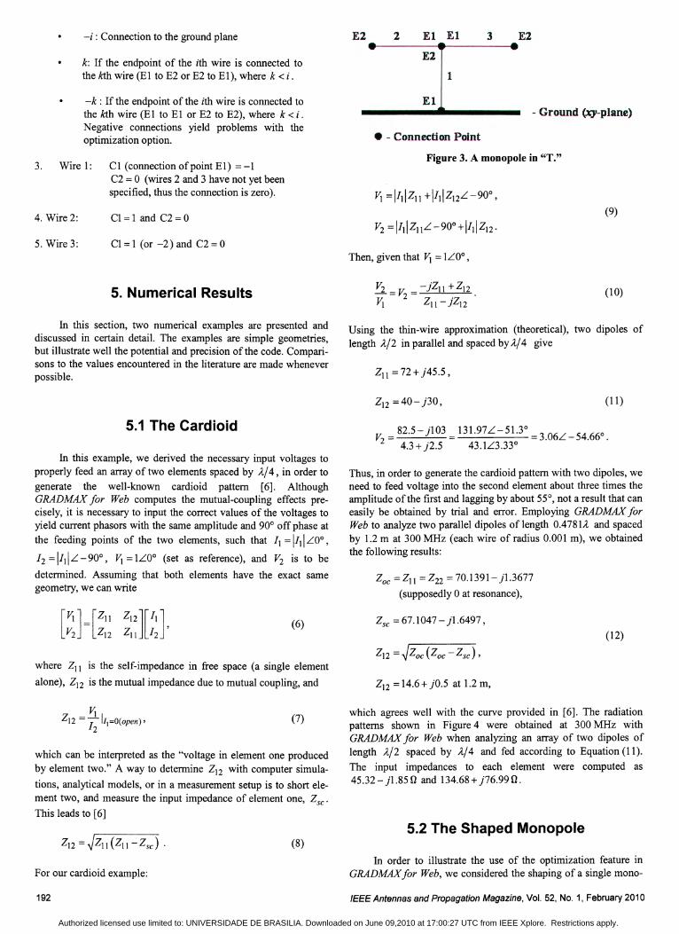
-i : Connection to the ground plane
k: If the endpoint of the ith wire is connected tothe kth wire (E1 to E2 or E2 to E1), where k < i.
E2 2 El El
E2
1
3 E2
-k : If the endpoint of the ith wire is connected tothe kth wire (E1 to E1 or E2 to E2), where k < i .Negative connections yield problems with theoptimization option.
El
• - Connection Point
- Ground (xy-plane)
3. Wire 1: C1 (connection of point E1) =-1C2 = 0 (wires 2 and 3 have not yet beenspecified, thus the connection is zero).
Figure 3. A monopole in "T."
4. Wire 2:
5. Wire 3:
Cl = 1 and C2 = 0
C1 = 1 (or -2) and C2 = 0
(9)
Then, given that Vi = 1LO°,
5. Numerical Results (10)
In this section, two numerical examples are presented anddiscussed in certain detail. The examples are simple geometries,but illustrate well the potential and precision of the code. Comparisons to the values encountered in the literature are made wheneverpossible.
Using the thin-wire approximation (theoretical), two dipoles oflength AI2 in parallel and spaced by AI4 give
Zl1 = 72+ j45.5,
Z12 =40- j30, (11)
5.1 The Cardioid
In this example, we derived the necessary input voltages toproperly feed an array of two elements spaced by A14, in order togenerate the well-known cardioid pattern [6]. AlthoughGRADMAX for Web computes the mutual-coupling effects precisely, it is necessary to input the correct values of the voltages toyield current phasors with the same amplitude and 90° off phase atthe feeding points of the two elements, such that I} = II} \LO° ,
12 = II}IL -900, Vi = 1LO° (set as reference), and V2 is to be
determined. Assuming that both elements have the exact samegeometry, we can write
V2
=82.5- j103 =131.97L-51.3° =3.06L-54.660 •
4.3 + j2.5 43.1L3.33°
Thus, in order to generate the cardioid pattern with two dipoles, weneed to feed voltage into the second element about three times theamplitude of the first and lagging by about 55°, not a result that caneasily be obtained by trial and error. Employing GRADMAX forWeb to analyze two parallel dipoles of length O.4781A and spacedby 1.2 m at 300 MHz (each wire of radius 0.001 m), we obtainedthe following results:
Zoe = Zl1 = Z22 = 70.1391- j1.3677
(supposedly 0 at resonance),
(6) Zse = 67.1047 - j1.6497 ,(12)
where Z11 is the self-impedance in free space (a single element
alone), Z12 is the mutual impedance due to mutual coupling, and Z12 =14.6+ jO.5 at 1.2 m,
which can be interpreted as the "voltage in element one producedby element two." A way to determine Z12 with computer simula-
tions, analytical models, or in a measurement setup is to short element two, and measure the input impedance of element one, Zse'
This leads to [6]
(7)
(8)
which agrees well with the curve provided in [6]. The radiationpatterns shown in Figure 4 were obtained at 300 MHz withGRADMAX for Web when analyzing an array of two dipoles oflength AI2 spaced by AI4 and fed according to Equation (11).
The input impedances to each element were computed as45.32- j1.850 and 134.68+ j76.990.
5.2 The Shaped Monopole
For our cardioid example:
192
In order to illustrate the use of the optimization feature inGRADMAX for Web, we considered the shaping of a single mono-
IEEEAntennasand Propagation Magazine, Vol. 52, No.1, February 2010
Authorized licensed use limited to: UNIVERSIDADE DE BRASILIA. Downloaded on June 09,2010 at 17:00:27 UTC from IEEE Xplore. Restrictions apply.

Shaped Monopole
0,70
0,60
0,50
0,40
0,30
0,20
0,10
0,00
0,0 0,1 0,2 0,3 0,4 0,5x-coordinate [m]
Figure 5. The shaped geometry for a 0.75A monopole asobtained with GRADMAX for Web after five iterations (themonopole was modeled with six pieces of straight wire).
pole modeled as six straight and connected wires. The code alsooffers the possibility of optimizing the spacing between the elements of an array of monopoles. The goal is always to maximizethe gain in the x direction.
A monopole of 0.75A (in order to have phase inversions inthe current distribution) was analyzed with GRADMAX for Web,yielding an input impedance of 70.42 + j20.35 (} at 300 MHz, and
a gain of 6.67 dBi (about 50° off the x direction). After five iterations, all in about 30 seconds with an Intel 2.4 GHz Core 2 quadCPU, the optimization process arrived at the geometry shown inFigure 5. The final computed input impedance was57.86+ j6.47(}, and a gain of 10.15dBi (about 2 dB FIB ratio).
The patterns are shown in Figure 6. Note that 20 segments per wirewere employed during the optimization, which does not correspondto the default values for the monopole example available in thecode.
The results of the optimization compared well with resultspreviously published in the literature [7], considering that they areall based on numerical optimizations with different analysis kernels. The maximum discrepancy between the angles with referenceto the vertical axis as computed by GRADMAX for Web and theangles published in [7] was about 16° for the fourth wire from theorigin, but others were much closer. The gain for the correspondingdipole, as computed and measured by [7], was 7.2 dBi, corresponding to 10.2 dBi for a monopole, which agreed fairly well withthe value of 10.15 dBi obtained with GRADMAXfor Web. In addi-
IEEE Antennasand Propagation Magazine, Vol. 52, No.1, February 2010
tion, other authors, such as [20], reported gains for the corresponding monopole in the range of 10 to 10.13 dBi, also very closeto the value herein obtained. Finally, the input resistance reportedin [7] was 86 (}, which differed somewhat from the value of57.86 (} computed by GRADMAXforWeb. However, that may beexplained by the number of segments used, as well as the modelingemployed in the implementation of the Method of Moments.
6. Conclusions
The code GRADMAXfor Web was introduced in this article.GRADMAX is a Java applet designed for analyzing and optimizingarrays of wire antennas, and runs directly from the Web browser onall common operating systems (Windows, Macintosh, Linux,Solaris, etc.). The analysis algorithm, based on the point-matchingtechnique of the Method of Moments (MININEe engine), wasbriefly discussed. The optimization layer, which employs the modified gradient method, was explained in more detail. Finally, twoexamples to illustrate the 'use of the analysis and optimizationcapabilities of the code were presented. The numerical results werecompared with the values available in the literature, indicatinggood precision for the code. GRADMAXfor Web can be consideredto be a valuable tool for teaching and research, due to its ease ofuse and access, combined with high accuracy and speed.
7. Acknowledgment
This work was partially supported by CNPq (BrazilianNational Research Council).
8. References
1. Richard Schneider and John Ross, "Antennas for the New Airwaves," IEEE Spectrum, 46, 2, February 2009, pp. 44-49.
2. Ulrich Reimers, "DVB - The Family of International Standardsfor Digital Video Broadcasting," Proceedings of the IEEE, 94, 1,January 2006, pp. 173-182.
3. Masaru Sakurai, "Digital Television Receiver for ISDB," Proceedings ofthe IEEE, 94, 1, January 2006, pp. 323-326.
4. E. K. Miller and G. 1. Burke, "Personal Computer Applicationsin Electromagnetics," IEEE Antennas and Propagation Newsletter,25,4, August 1983, pp. 4-9.
5. S. T. Li, J. W. Rockway, 1. C. Logan and D. W. S. Tam, Microcomputer Tools for Communications Engineering, Norwood, MA,Artech House, 1983.
6. W. L. Stutzman and G. A. Thiele, Antenna Theory and Design,New York, John Wiley and Sons, 1981.
7. F. M. Landstorfer and R. R. Sacher, Optimization of WireAntennas, London, John Wiley and Sons, 1986.
8. 4nec2, http.z/home.ict.nl/r-arivoors.
193
Authorized licensed use limited to: UNIVERSIDADE DE BRASILIA. Downloaded on June 09,2010 at 17:00:27 UTC from IEEE Xplore. Restrictions apply.

9. L. Mattioni and G. Marrocco, "BLADE: A Broadband LoadedAntenna DEsigner," IEEE Antennas and Propagation Magazine,48, 5, October 2006, pp. 120-129.
10. Sergey Makarov, "MoM Antenna Simulations with MATLAB:RWG Basis Functions," IEEE Antennas and Propagation Magazine, 43, 5, October 2001, pp. 100-107.
11. Antonije R. Djordjevic, Miodrag B. Bazdar, Vladimir V.Petrovic, Dragan I. Olean, Tapan K. Sarkar, and Roger F.Harrington, A WAS for Windows Version 2.0: Analysis of WireAntennas and Scatterers, Software and User's Manual, Norwood,MA, Artech House, 2002.
12. R. Rabelo, M. Terada and W. Stutzman, "Analysis of ReflectorAntennas through the World Wide Web," IEEE Antennas andPropagation Magazine, 49, 4, April 2007, p. 113-116.
13. C. Bachiller, H. Esteban, J. V. Morro, A. Belenguer and V.Boria, "Online Application for the Representation of RadiationPattern of Antenna Arrays," IEEE Antennas and PropagationMagazine, 50, 2, February 2008, p. 198-201.
14. Digital Maestro, http://amanogawa.com.
15. W. A. Davis and R. Mittra, "A New Approach to the ThinScatterer Problem Using the Hybrid Equations," IEEE Transactions on Antennas and Propagation, AP-25, 5, May 1977, pp. 402406.
16. N. 1. Champagne and D. R. Wilton, "The Analysis of ThinWires Using Higher Order Elements and Basis Functions," IEEETransactions on Antennas and Propagation, AP-54, 12, December2006, pp. 3815-3821.
17. E. E. Altshuler and D. S. Linden, "Wire-Antenna Design UsingGenetic Algorithms," IEEE Antennas and Propagation Magazine,39, 2, April 1997, p. 33-43.
18. Y. Rahmat-Samii and E. Michielssen, Electromagnetic Optimization by Genetic Algorithms, New York, John Wiley and Sons,1999.
19. D. Correia, A. J. M. Soares and M. A. B. Terada, "Optimization of Gain, Impedance and Bandwidth in Yagi-Uda AntennasUsing Genetic Algorithm," 1999 SBMO/IEEE MTT-S, AP-S andLEOS International Microwave and Optoelectronics Conference,Rio de Janeiro, August 9-12, 1999.
20. D. K. Cheng and C. H. Liang, "Shaped Wire Antennas withMaximum Directivity," Electronics Letters, 18, 19, September 16,1982,pp. 816-818.~ID
194 IEEEAntennasand Propagation Magazine, Vol. 52, No.1, February 2010
Authorized licensed use limited to: UNIVERSIDADE DE BRASILIA. Downloaded on June 09,2010 at 17:00:27 UTC from IEEE Xplore. Restrictions apply.