foreword - echomaster marine ltd. instruction... · jlr-10 gps compass 6 table of contents foreword...
TRANSCRIPT

JLR-10 GPS Compass
1
Foreword
� Thoroughly read this instruction manual before commencing the equipment operation.
� We would recommend you to keep this manual nearby the equipment to ensure ready access to it.
It should give you information on how to cope with a given situation that may arise during the equipment
operation.
Thank you for purchasing the JRC GPS Compass JLR-10.
This unit uses the signals from the GPS satellites and measures the heading of the ship.

JLR-10 GPS Compass
2
Before Commencing the Equipment Operation
Graphical SymbolsSeveral graphical symbols are used in this manual to ensure safety and proper
operation of the equipment and to avoid possible human injury or property
damage. The symbols and their meanings are shown below. We would
recommend you to carefully read the manual to obtain a thorough
understanding on these symbols.
Examples of the Symbols
The symbols shown in the △ mark represent those that require attention
(including the potential dangers and warnings).
A tangible instruction is shown in the symbol. For example, the symbol shown
to the left indicates that one is likely to get an electric shock.
The circle symbols with a slash from the upper left to the right bottom
represent the specific actions prohibited to avoid potential hazards.
A tangible instruction is shown in the symbol. For example, the symbol shown
to the left indicates that the disassembly is prohibited.
The black circle symbols represent the obligatory actions or instructions to
avoid potential hazards.
A tangible instruction is shown in the symbol. For example, the symbol shown
to the left indicates that the power supply plug needs to be disconnected.
Instructions shown with this symbol represent those
that can cause death or severe injury, if not observed.
Instructions shown with this symbol represent those
that can cause injury or property damage, if not
observed.
Don’tdisassemble
Don’t
Disconnectthe power
supply plug
Instruction
Electric shock
WARNING
CAUTION

JLR-10 GPS Compass
3
POWER
OFF!
Precautions Upon Equipment Operation
Do not disassemble or modify the equipment. Failure
to observe the instruction can cause a fire, electric
shock, or equipment failure.
Do not insert or remove the power cord or operate
switches with a wet hand.
Otherwise, you may suffer from an electrical shock.
Operate the equipment only at the power supply volt-
age of DC 12V or 24V. Failure to observe this instruc-
tion can cause a fire, electric shock, or equipment fail-
ure.
Do not scratch, damage, or modify the power supply
and antenna cable. It may be damaged to cause a fire
or electric shock if it is loaded with a heavy item, heated,
pulled, or excessively bent.
Do not operate setting change used as the hindrance
of navigation etc. during operation.
Immediately turn the power off and disconnect the
power supply cable if the equipment is generating any
smoke or odor, or found overheated. Then, promptly
inform our local service agent of the symptom to have
it corrected. Prolonged equipment operation under
such a condition can cause a fire or electric shock.
WARNING

JLR-10 GPS Compass
4
Thinner
Benz
ine
No
Do not allow the Display Unit to fall or immerse in wa-
ter. The equipment can be damaged.
When removing the power and antenna cord, be sure
to remove the cord terminal correctly. If the cord is
pulled, the cord may be damaged resulting in a fire or
an electrical shock.
When cleaning the surface, do not use any or-
ganic solvent such as thinner or benzine.
Otherwise, the painting on the surface may be
damaged.
For cleaning the surface, remove the dust and
debris and wipe with a clean dry cloth.
Our contactsRefer to the List of Offices attached at the end of this manual.
CAUTION
Do not place a vessel containing water, etc. or a metal-
lic object on the Processing Unit.
When water spills or when water or the object enters the
set, a fire, an electrical shock, or a failure may occur.
Use the GPS compass merely as a supporting device
for navigation.
Further, the final judgment on steering the ship should
always be done at the discretion of the person steer-
ing the ship.
WARNING

JLR-10 GPS Compass
5
Appearance of the Equipment
NNN-10 Processing Unit NWZ-4551G Display Unit
NAY-1000 Antenna

JLR-10 GPS Compass
6
Table of Contents
Foreword ............................................................................................................................. 1
Before Commencing the Equipment Operation................................................................... 2
Precautions Upon Equipment Operation ............................................................................. 3
Appearance of the Equipment ............................................................................................. 5
Key Terms............................................................................................................................ 9
1. Equipment Overview ................................................................................................... 111.1 Functions .......................................................................................................................................111.2 Features .........................................................................................................................................121.3 Configuration .................................................................................................................................131.4 Construction ...................................................................................................................................14
1.5 General System Diagram...............................................................................................................17
2. Names and Functions of Parts .................................................................................... 182.1 Antenna .........................................................................................................................................182.2 Processing Unit ..............................................................................................................................192.3 Display Unit ....................................................................................................................................20
2.3.1 Operation Panel of the Display Unit .........................................................................................20
2.3.2 Rear Panel of the Display Unit .................................................................................................22
3. Installation ................................................................................................................... 233.1 Installation of the Antenna .............................................................................................................23
3.1.1 Choosing the Location .............................................................................................................233.1.2 Assembling Method of the Antenna .........................................................................................243.1.3 Installation Method of the Antenna ..........................................................................................26
3.2 Installation of the Processing Unit .................................................................................................283.2.1 Installation on the Floor ...........................................................................................................283.2.2 Installation on the Wall .............................................................................................................303.2.3 Installation toward the Side ......................................................................................................32
3.3 Installation of the Display Unit ........................................................................................................333.3.1 Choosing the Location .............................................................................................................333.3.2 Mounting the Unit ....................................................................................................................34
3.4 Connection of the Equipment ........................................................................................................363.4.1 Connection of the Power Supply Cable ...................................................................................363.4.2 Connection of the Grounding Line ...........................................................................................373.4.3 Connection of the Antenna Cable ............................................................................................373.4.4 Connection of the Display Unit Cable ......................................................................................383.4.5 Connection of the Radar Cable ...............................................................................................403.4.6 Confirmation after Installation ..................................................................................................41
3.5 Connection of the Optional Equipment ..........................................................................................433.5.1 Connection of the GPS Repecon ............................................................................................433.5.2 Connection of the DGPS Beacon Receiver .............................................................................453.5.3 Connection of the DGPS Receiver ..........................................................................................463.5.4 Connection of the Other Equipment ........................................................................................47

JLR-10 GPS Compass
7
3.6 Measures for the Electromagnetic Interference .............................................................................483.6.1 Checks before the Connection ................................................................................................483.6.2 Checks before the Navigation ..................................................................................................48
4. Operation .................................................................................................................... 494.1 Overview ........................................................................................................................................494.2 Turning the Unit ON/OFF ...............................................................................................................504.3 Selecting Display Language ..........................................................................................................514.4 Switching between Main Display Modes........................................................................................524.5 Main Display Modes.......................................................................................................................54
4.5.1 HEADING Display Mode ..........................................................................................................544.5.2 POSITION Display Mode .........................................................................................................584.5.3 NAVIGATION Display Mode ....................................................................................................584.5.4 CDI Display Mode ....................................................................................................................594.5.5 PLOT Display Mode and Setting the Plot Scale ......................................................................604.5.6 WAYPOINT Display Mode .......................................................................................................614.5.7 ROUTE Display Mode .............................................................................................................614.5.8 STATUS Display Mode .............................................................................................................62
4.6 Basic Menu Selection Operations ..................................................................................................644.7 Adjusting Contrast and Backlighting ..............................................................................................664.8 Setting the Heading .......................................................................................................................66
4.8.1 Manually Setting the Heading ..................................................................................................664.8.2 Selecting the Output Format of Heading Data .........................................................................674.8.3 Setting the Installation Direction of Processing Unit ................................................................67
4.9 Setting Alarms (Arrival/Anchor/Off-course/DGPS) ........................................................................684.10 Navigation Using Direct Route [GOTO] .........................................................................................704.11 Navigation according to Route Plans .............................................................................................714.12 Entering Current Position as a Waypoint [EVENT] ........................................................................724.13 Man-Over-Board Mode [MOB] .......................................................................................................734.14 Position Correction/Geodetic System Correction/Magnetic Compass Correction .........................734.15 Setting Navigation Display Modes and Units .................................................................................754.16 Setting CDI Range and Display Time Format ................................................................................764.17 Setting Plotting Information ............................................................................................................764.18 Entering Waypoints ........................................................................................................................77
4.18.1 Editing Waypoint Lists ..............................................................................................................784.18.2 Storing Waypoints ....................................................................................................................784.18.3 Entering, Copying and Measuring Waypoints ..........................................................................804.18.4 Sorting Waypoint Names .........................................................................................................82
4.19 Setting Route Plans .......................................................................................................................824.19.1 Making a Route Plan ...............................................................................................................834.19.2 Editing Route Plan ...................................................................................................................844.19.3 Erasing Route Plans ................................................................................................................85
4.20 Setting GPS Information ................................................................................................................864.20.1 Setting Position Fix Mode and Averaging for GPS ..................................................................864.20.2 Initializing GPS ........................................................................................................................874.20.3 Setting DGPS Beacon .............................................................................................................88

JLR-10 GPS Compass
8
4.21 Setting Output Level and Transmitting/Receiving Memory Data ....................................................894.22 Performing Master Reset ...............................................................................................................91
5. Maintenance and Inspection ....................................................................................... 92
6. Measures for the Operating Environment ................................................................... 93
7. After-sale Services ...................................................................................................... 94
8. Disposal ...................................................................................................................... 958.1 Disposal of the Equipment .............................................................................................................958.2 Disposal of the Used Battery .........................................................................................................95
9. Specifications .............................................................................................................. 96
AppendicesAppendix 1 Optional Unit .................................................................................................................98
� Summary of GPS Repecon .......................................................................................98� Summary of DGPS Beacon Receiver .......................................................................99� Summary of DGPS Receiver ...................................................................................100� Summary of OPTION Cable ....................................................................................101� Summary of NMEA Cable .......................................................................................102
Appendix 2 Cable Connection of the Attached Connector (N-P-5-2) .............................................103Appendix 3-A Message List ...............................................................................................................105
� Error message .........................................................................................................105� Navigation alarms ....................................................................................................105� Operation message .................................................................................................106� Bearing alarms ........................................................................................................107� Antenna alarms .......................................................................................................107
Appendix 3-B Geodetic System Tables .............................................................................................108Appendix 4 Data Output .................................................................................................................110
� Data output from Processing Unit ...........................................................................110� Data output from Display Unit ..................................................................................115
Appendix 5 Waypoint/Route Plan Data In/Output ..........................................................................119Appendix 6 Waypoint List ...............................................................................................................120
INDEX ............................................................................................................................. 122
� List of Offices (Back Cover)

JLR-10 GPS Compass
9
Key Terms
Term DescriptionGPS satellites The term is an acronym that represents the Global Positioning System,
which is managed by the US Department of Defense to support its
navigation aid system.
DGPS The term is an acronym that represents the Differential Global
Positioning System, which is a system to improve the position fixing
accuracy by receiving the correction data with a beacon receiver for a
given GPS satellite, which is transmitted by the beacon station with a
known position.
Position fixing The term means to obtain the current position of your vessel with the
GPS or DGPS receiver.
2D (Two-dimensional position fixing) The term 2D means the position fixing with data obtained from the satel-
lites and antenna height information.
3D (Three-dimensional position fixing) The term 3D means the position fixing with four or more satellites infor-
mation only.
HDOP The term is an acronym that represents the Horizontal Dilution of
Precision, which reflects the position fixing accuracy. The accuracy
increases as the value decreases.
The value increases when the satellites are gathered close to each other,
and it reduces when the satellites are spattered, which in turn means
increased accuracy.
Route plan This is the plan that consists of the multiple waypoints registered in the
order of navigation.
CDI The term is an acronym that represents the Course Deviation Indicator,
which includes information on the deviation from a given planned course
and direction to be steered.
Arrival alarm The alarm notifies that your vessel has arrived at the preset distance
from a given destination.
Anchor alarm The alarm notifies that your vessel has drifted away from the destination
by the preset distance.
Off-course alarm The alarm notifies that your vessel has been deviated from the planned
course by the preset distance.

JLR-10 GPS Compass
10
Boundary alarm The alarm notifies that your vessel has crossed a preset boundary line.
Automatic sequencing mode The function automatically switches to the next destination after your
vessel has entered the preset arrival alarm range of a previous destina-
tion point according to a route navigation plan.
Manual sequencing mode The function allows the operator to manually change to the next leg of a
route during navigation based on a route plan.
Default values The values represented by the factory settings.
NMEA 0183 This is a standard specified by an international organization called the
National Marine Electrical Association (NMEA) to specify the
requirements for the data communications among various equipment.
Master reset This function clears all the settings on the Processing Unit and the Dis-
play Unit . Note that all the settings will be cleared if the function is
performed and reset to factory defaults.
Initialization A maximum duration of about 3 minutes is required for position fixing if
the equipment is to be operated for the first time after the installation or
the master reset function has been performed. The initialization time
can be reduced for position fixing by manually entering the estimated
position, time, and antenna height.
Course A direction made good, obtained by connecting the positions tracked by
the vessel, which is mainly the direction displayed by the GPS.
Bearing (Heading) An angle formed between the local meridian and the orientation of the
bow during the navigation, which is mainly displayed on the GPS com-
pass (this unit), gyro compass or magnetic compass.

JLR-10 GPS Compass
11
1. Equipment Overview
1.1 Functions
This unit determines the heading of the ship by measuring the orientation between two antennas using the
signal from the GPS satellites.
It is not only possible to measure the heading with a high accuracy continuously for 24 hours all over the
world and in all weather conditions using the GPS satellites, but also it measures the position. And when the
DGPS beacon receiver is connected the measurement accuracy of position can be further enhanced by receiv-
ing the correction data from the DGPS beacon station.
Since this unit outputs the bearing information at high speed, if this unit is connected to Radar units JMA-
3800 or JMA-3900 manufactured by our company, it is possible to fully take advantage of the Radar and ARPA.

JLR-10 GPS Compass
12
1.2 Features
This unit has the following features:
• JRC specific dual antenna method
A dual antenna method that as applied has excellent bearing precision and reception rate, and can be
easily installed.
• Low maintainance
Unlike a gyro compass, this unit does not require as often as inspection or as much maintainance.
• Can be used soon after switching ON the power.
The measurement of heading can be done from about 3 minutes (standard value) after switching ON the
power.
• Excellent tracking capacity
The tracking capacity is much better than that of a gyro compass.
• Can be connected directly to a JRC Radar.
Since this unit outputs the data to the JRC Radar at a high speed, it is possible to fully bring out the
performance capabilities of the Radar and any ARPA functions.
• Output of the orientation, position, and speed data.
This unit also has the functions of a GPS receiver.
• Synchronization signal can be output (optional).
It is possible to connect a synchronous type repeater using the optional interface.
• Large-sized dot matrix LCD display with back light.
A screen that is easy to see and has a large amount of information can be displayed because of the use of
a large-sized LCD display. Both the keyboard and display are provided with a back light, so night operation
is no problem.
• Graphic display
In the CDI display mode, the direction in which the ship has to be steered can be easily seen, thereby
helping for efficient fuel saving navigation.
In the plot display mode, it is not only possible to display the path that has already been traversed but also
possible to display the symbols registered beforehand for the different destinations.
• Menu selection method makes operation easy to grasp.
From the menu display on the screen, it is possible to understand the selections intuitively, thereby making
the operation easy. Selection and confirmation of the menu is done using a dial which is very easy to
operate.
• Customizing
Since a variety of setting items have been provided, it is possible to create a navigation system with the
preferences of an individual user.
• One-touch display installation and removal.
The Display Unit can be easily removed from the frame by pressing the button at the back of the Display
Unit.
• Seven languages are supported.

JLR-10 GPS Compass
13
1.3 Configuration
This configuration consists of the three units of the Antenna, the Processing Unit, and the Display Unit.
Further, a Digital/Synchro Converter unit for a repeater (GPS repecon), a DGPS receiver and a DGPS
beacon receiver can be connected as optional.
The following table gives a list of the constituting items.
Antenna
Processing UnitCables
Antenna CablesDisplay Unit Cables
Radar CablesPower Supply Cables
Display UnitInstruction ManualInstallation Parts
Pole Mounting KitScrewsSelf-bonding Tape
Spare PartsFuse
NAY-1000
NNN-10
CFQ-6561CFQ-6557
CFQ-6558CFQ-6556NWZ-4551GDC50-JLR-10
(See packing list)MPTG30149SUMITAPE N
MF51NN-2A
Antenna Units (1 bow, 1 stern)Includes Pre-amplifiere
15m (5D-SFAE), two cables5m (For connecting Processing Unit
– Display Unit)15m (For connecting Processing Unit– Radar)2m
English
For installation of AntennaFor installation of Processing UnitFor waterproofing Antenna Connector (TNC)
2A
1
1
1 set1
1111
1 set1 set
1
1
Name Type Q'ty Remarks
Composition
GPS RepeconDGPS Receiver(DGPS 212)DGPS Beacon Receiver"Y" Cable
OPTION CableNMEA Cable
Display Unit Data Cable
Flash Mount Kit
NID-2001JLR-4331
NRB-2JCFQ-6722
CFQ-6559CFQ-6560
CFQ-6721
MPTG30432
Digital/Synchro Converter Unit
For connecting DGPS Receiver/DGPS Beacon ReceiverFor connecting GPS RepeconFor connecting various navigation equipmentdevicesFor connecting various navigation equipmentdevicesFor in/outputing waypoint/route plan dataFor flash mount of Display Unit
11
1
11
1
1
Name Type Q'ty Remarks
Option
JLR-10 G
PS
Com
pass
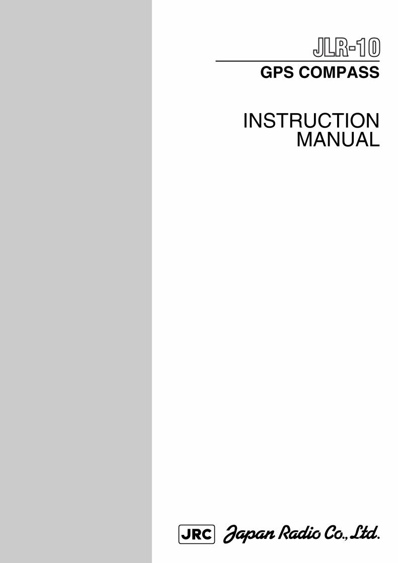
14 1.4C
on
structio
n
(1)O
utlin
e draw
ing
of N
AY
-1000 An
tenn
a
676
500
(Installable range is ø42.7 to 48.6)Mast (Preparation in dock)
HEADING
ø176
6550
115
230
Unit : m
m
Mass : approx. 3.2
O
Fig
. 1-1
JLR-10 G
PS
Com
pass
15
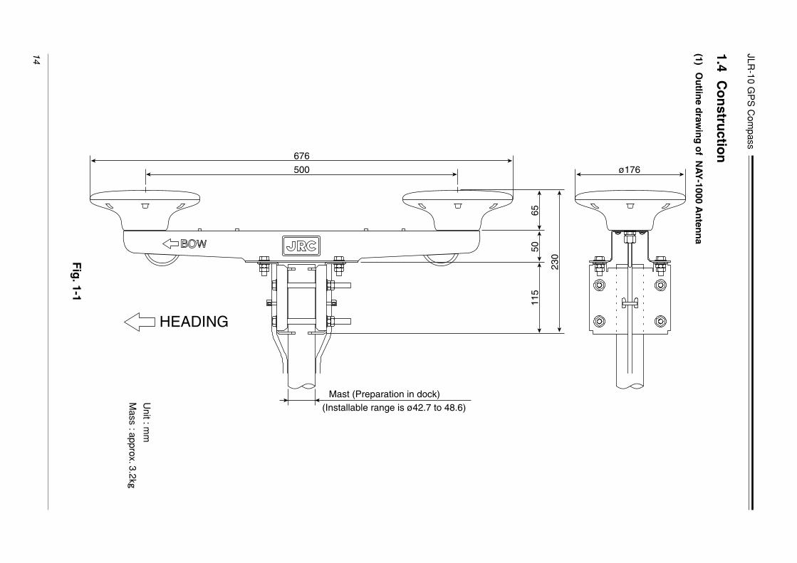
(2)O
utlin
e draw
ing
of N
NN
-10 Pro
cessing
Un
it
HEADING
137
152
150
6.6
6
230
230
175
Mounting hole
(23)27.5 27.5
22
Detailes of Mounting hole
Unit : m
m
Mass : approx. 2.9
O
Fig
. 1-2

JLR-10 G
PS
Com
pass
16 (3)O
utlin
e draw
ing
of N
ZW
-4551G D
isplay U
nit
MODE
MENU
MOB EVENT
GOTO
CONTDIM
CLROFF
PWROFF
PUSH
13811
721
46.5 84 1010
197
46.5
124
70
28 74 1012
4-ø6Mounting hole
GPS COMPASS
Unit : m
m
Mass : approx. 0.9
O
Fig
. 1-3

JLR-10 GPS Compass
17
1.5 General System Diagram
2.5D-2V0.15 m(TNC)
CFQ-65615D-SFAE
15 m
CFQ-6557Display Unit Cable5m
CFQ-6558Radar Cable15m
✽ CFQ-6560NMEA Cable
✽ CFQ-6559OPTION Cable
(N)
Navigation Data
CFQ-6556Power Supply Cable
2m
NAY-1000 Antenna
Power Supply+12/24 VDC
NNN-10ProcessingUnit
NWZ-4551GDisplay Unit
Radar
Digital/SynchroConverter
“✽” mark is optional
NID2001GPS Repecon Repeater etc.
Navigation DataWaypoint/Route Plan Data
✽
or
To Display Unit
CFQ-6557Display Unit Cable
JLR-4331DGPS Receiver
NRB-2JDGPS Beacon Receiver
✽ CFQ-6722Y Cable
✽ CFQ-6721Display Unit Data Cable
To Processing Unit
Fig. 1-4

JLR-10 GPS Compass
18
2. Names and Functions of Parts
2.1 Antenna
Fig. 2-1
q
e
r
w
t
e
r
q
w
No. Name Function
Incorporates an antenna preamplifier for bow direction
Incorporates an antenna preamplifier for stern direction
2.5D coaxial cable
Bow Antenna Unit
Stern Antenna Unit
Coaxial Cablee
r A female TNC connector on the attached antenna cable.
Connects to the male TNC connector on 15M antenna extention cable.
TNC Connector
t Antenna holding bracket.Antenna Stay

JLR-10 GPS Compass
19
2.2 Processing Unit
POWER FUSE2A
ANT BOW ANT STERN DISP
RADAR NMEA OPTION
GND DC12V/24V
q
w
r
t
u
i
o
e
y
!0
Fig. 2-2
q
No. Name Function
When the switch is pressed, the lamp is lit and the power is turned on. When
the switch is pressed again, the lamp and the power are turned off.
Power Switch
w A 2A power fuse is provided.Fuse
e Connector for the bow antenna cable.Bow Antenna Connector
r Connector for the stern antenna cable.Stern Antenna Connector
t Connector for the Display Unit cable (CFQ-6557).Display Connector
y Connector for the radar cable (CFQ-6558).Radar Connector
u Connector for an optional NMEA cable (CFQ-6560).NMEA Connector
i Connector for an optional OPTION cable (CFQ-6559).Option Connector
o Connector for the power cable (CFQ-6556).DC12V/24V Connector
!0 Terminal for hull ground connection.Terminal “GND”
JLR-10 GPS Compass
20
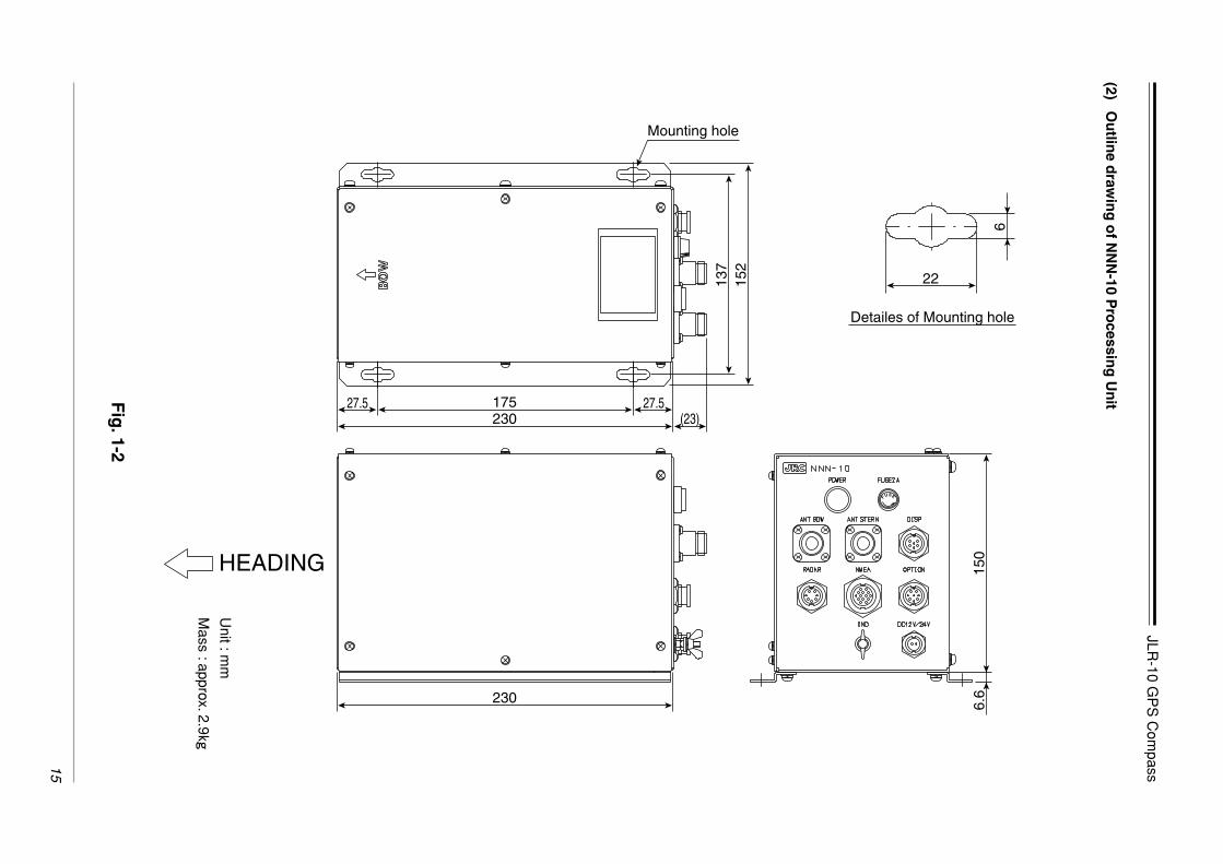
2.3 Display Unit
2.3.1 Operation Panel of the Display Unit
The illustration shows the keys on the operation panel and their functions.
MODE
MENU
MOB EVENT
GOTO
CONTDIM
CLROFF
PWROFF
PUSH
GPS COMPASS
q
we
r
t
y
u
io
q
w
No. Name Function
• Press this key in any mode exept “MOB” to select main display mode.
• Press this key in the “Select Mode” display to return to previous dis-
play mode.
• Turn to select menu. (Turn dial counterclockwise to scroll downward
and turn it clockwise to scroll upward.)
• Selects menu items.
• Sets numeric values when menu items are numeric entry. (The num-
bers change faster, when the dial is turned faster.)
• Press the dial to select a menu or to enter a setting.
• When following a route sequence manually, use the dial to step the
next waypoint.
This function is available in the following display modes:
“HEADING”, “POSITION”, “NAVIGATION” and “CDI” displays
Mode
Down
Dial
Up
Ent (Press dial)
Fig. 2-3
JLR-10 GPS Compass
21
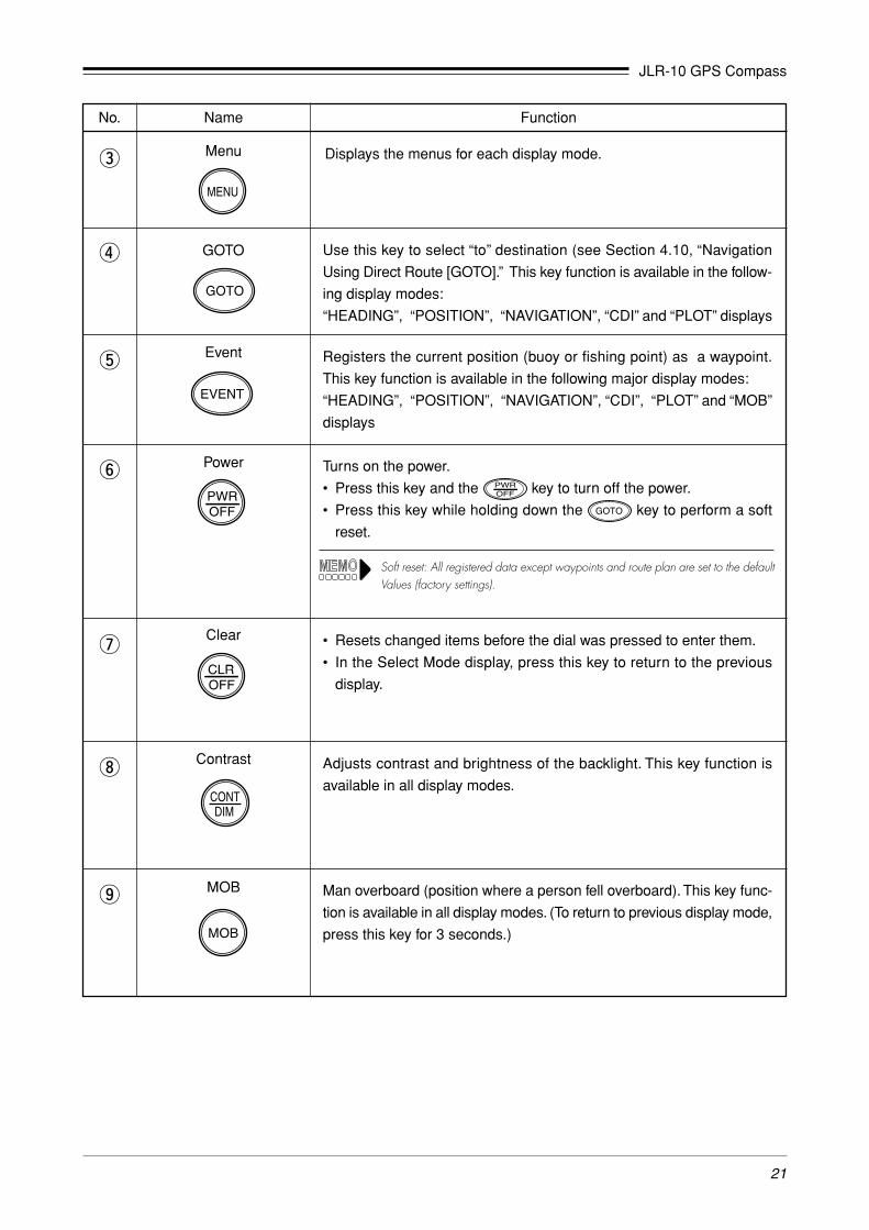
e Displays the menus for each display mode.
r
y
t
No. Name Function
Use this key to select “to” destination (see Section 4.10, “Navigation
Using Direct Route [GOTO].” This key function is available in the follow-
ing display modes:
“HEADING”, “POSITION”, “NAVIGATION”, “CDI” and “PLOT” displays
Registers the current position (buoy or fishing point) as a waypoint.
This key function is available in the following major display modes:
“HEADING”, “POSITION”, “NAVIGATION”, “CDI”, “PLOT” and “MOB”
displays
Turns on the power.
• Press this key and the key to turn off the power.
• Press this key while holding down the key to perform a soft
reset.
Adjusts contrast and brightness of the backlight. This key function is
available in all display modes.
Soft reset: All registered data except waypoints and route plan are set to the defaultValues (factory settings).
o
u
i
Man overboard (position where a person fell overboard). This key func-
tion is available in all display modes. (To return to previous display mode,
press this key for 3 seconds.)
• Resets changed items before the dial was pressed to enter them.
• In the Select Mode display, press this key to return to the previous
display.
Menu
GOTO
Clear
Event
Power
MOB
Contrast
JLR-10 GPS Compass
22
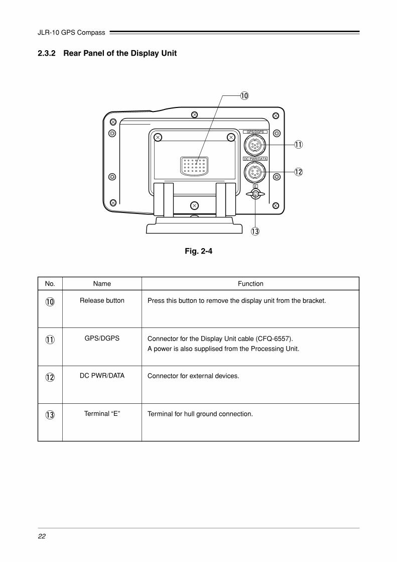
2.3.2 Rear Panel of the Display Unit
GPS/DGPS
DC PWR/DATA
E
!0
!1
!2
!3
Fig. 2-4
!0
!1
No. Name Function
Press this button to remove the display unit from the bracket.
Connector for the Display Unit cable (CFQ-6557).
A power is also supplised from the Processing Unit.
Connector for external devices.
Release button
GPS/DGPS
DC PWR/DATA!2
!3 Terminal for hull ground connection.Terminal “E”

JLR-10 GPS Compass
23
CAUTION
3. Installation
3.1 Installation of the Antenna
3.1.1 Choosing the Location
When connecting the cable attached to the equipment, do not bend it to an
acute angle, twist it, or impart excessive force. Cracks or damage to the
coating can cause a fire or electric shock.
Do not install the antenna where there is excessive vibration.
Accidents can be caused by receiving poor.
Install the antenna where there is no viewing obstacle, in order to ensure that
GPS signals can be directly received from satellites without interference or
reflection of signals from surrounding objects.
Whenever possible, select a place having the following characteristics.
If it is difficult to find an ideal site, select a place temporarily and install the antennas.
Conduct a test to make sure that the proper performance can be obtained and then fix
the antenna in position. If it is installed at an improper place, bearing accuracy is poorer,
and accidents can be caused.
1. An open space which allows uniform reception of satellite signals.
2. Far away from any high power transmission antennas.
3. Outside of any radar beams.
4. Away from the inmarsat antenna by at less 5 meters and below the level of its
antenna.
5. Away from the antenna of a direction finder, VHF or MF/HF by 5 meters or
more.
6. Away from a magnetic compass by at least 1 meter.
JLR-10 GPS Compass
24
Heading
Bolt head
Bolt (M8 x 120)
Bolt (M8 x 25)
Antenna (NAY-1000)
Wind water proofing tapeat the connection.
(See to step e)
Wind water proofing tapeat the connection.(See to step e)
Flat washer
Flat washer
Flat washer
Lock Nut
Nut
Flat washer
Lock Nut
Nut
Fixing bracket
Fixing bracket
Tie wrap (six places)
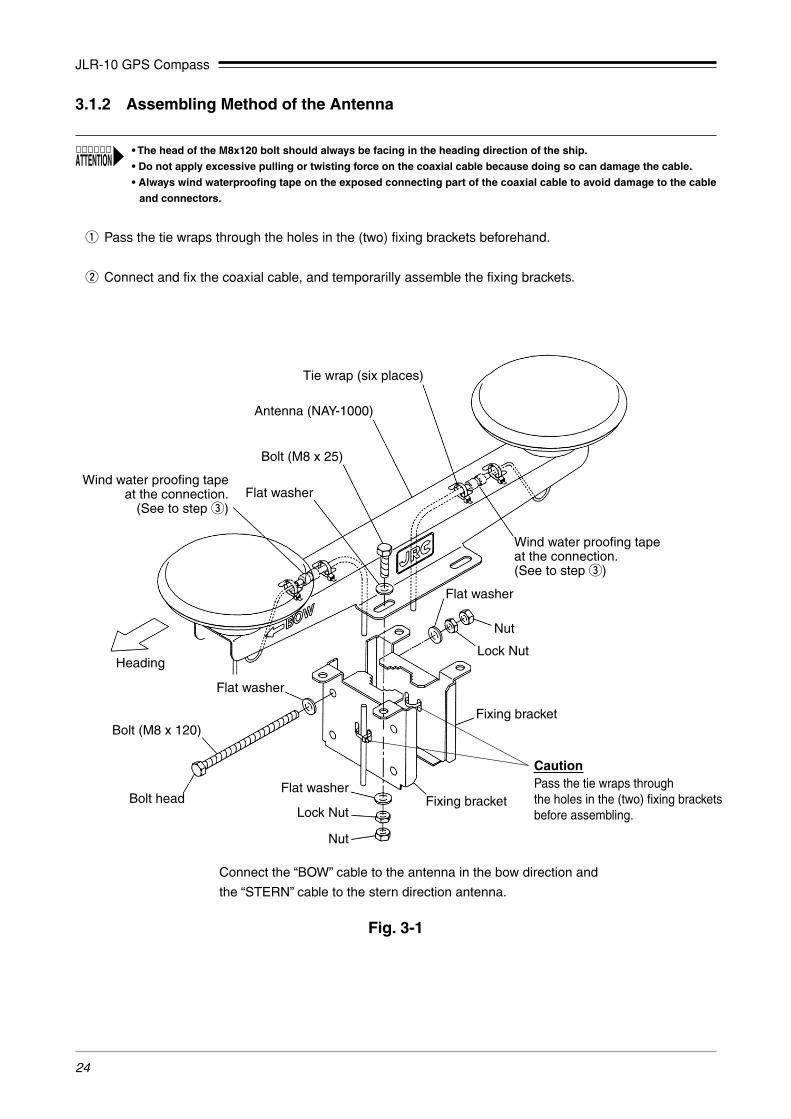
Connect the “BOW” cable to the antenna in the bow direction and
the “STERN” cable to the stern direction antenna.
CautionPass the tie wraps throughthe holes in the (two) fixing bracketsbefore assembling.
Fig. 3-1
3.1.2 Assembling Method of the Antenna
q Pass the tie wraps through the holes in the (two) fixing brackets beforehand.
w Connect and fix the coaxial cable, and temporarilly assemble the fixing brackets.
• The head of the M8x120 bolt should always be facing in the heading direction of the ship.
• Do not apply excessive pulling or twisting force on the coaxial cable because doing so can damage the cable.
• Always wind waterproofing tape on the exposed connecting part of the coaxial cable to avoid damage to the cable
and connectors.

JLR-10 GPS Compass
25
Fig. 3-2
e Apply waterproofing processing to the cable connection section.
Seal the junction of connectors with self-bonding tape and PVC tape for waterproofing.
Seal the junction of connectors with self-bonding tape and PVC tape for waterproofing.
(1) Self-bonding tape for seal
Coil the self-bonding tape to connectors with three layers, covering the joint to
double it’s length. After coiling, make a quick bonding by pressure of fingers.
Fig. 3-3
(2) PVC tape for protection
Coil PVC tape to three layers without stretching. After coiling, make a perfect
bonding by pressure of fingers.
To the Processing Unit To the Antenna Unit
Connector
q PVC tapew Self-bonding
Coiling direction

JLR-10 GPS Compass
26
3.1.3 Installation Method of the Antenna
Fix the Antenna on a mast, etc.
q Place the Antenna on the mast, and make the “BOW” arrow mark face in the heading of the ship.
w Tighten the bolts of the fixing bracket in the order A-B.
If the Antenna is installed at a location with severe vibration or shock, take
some measures to prevent such vibrations of the Antenna.
CAUTION
• When installing the antenna, make sure that the “BOW” arrow mark faces the bow. To install an antenna in a direction
other than facing the bow, a separate setting is required.
• Since this unit uses GPS, make sure that there are no obstructions that interfere with radio waves above or around
the installed unit.
• Tighten four bolts A gradually and firmly with equal strength.
If any one of the bolts is quickly tightened separately, the nut may strip the thread of the screw.

JLR-10 GPS Compass
27
Fixing bracket
Heading
Mounting torque 784N·cm(80Of·cm)
The top of the mast
Mast (dockyard supply)Outer diameter of the mast ø42.7 to ø48.6
Let the top of the mastgo to the top of the line.
(1.25 to 1.5 inch)
Mounting torque 1715N·cm(175Of·cm)
Mast
Fig. 3-4

JLR-10 GPS Compass
28
3.2 Installation of the Processing Unit
3.2.1 Installation on the Floor
To install the Processing Unit on the floor, allocate installation space as shown in Fig. 3-5. Then, install the
unit according to the following procedure.
q Decide on a Processing Unit installation position. Mark four sections for installation of screw positions.
See Fig. 3-5 for the hole size of the installation screws.
w Screw in the attached tapping screws in the marked positions leaving them about 3mm above the floor.
e Screw the tapping screws to the Processing Unit installation holes and attach the Processing Unit on the
floor.
r While attaching the Processing Unit on the floor, slide the Processing Unit so that the tapping screws are
set at the end of the installation holes and tighten the screws. Since the Processing Unit may move while
the screws are tightened, press the Processing Unit while tightening the screws.
t Check that the Processing Unit is firmly fixed on the floor.
This unit can be removed by merely loosening the screws and sliding the unit.The actual fixing with screws will be about 8mm to the front or back from the position shown in the figure.
• Always install the Processing Unit so that the connector surface having labels for each connector is facing upward
as shown in Fig. 3-5.
• Make sure the “BOW” mark faces the bow. If not facing the bow, a separate setting is required.

JLR-10 GPS Compass
29
MIN92
MIN48
MIN17
8
MIN15
0MIN
2023
0
MIN20
Install the four attachedM5 screws.
MIN100MIN320
MIN100✽✽
120
MIN17
715
7
R5R3
22 16
6
Details figure of part A(1:1)
MIN40
0
Hea
ding
✽✽
175
MIN92137
Part A
The size indicated by “✽” also indicates the minimum maintenance space.
Unit : mm
Fig. 3-5

JLR-10 GPS Compass
30
3.2.2 Installation on the Wall
To install the Processing Unit on a wall, allocate installation space as shown in Fig. 3-6. Then, install the unit
according to the following procedure.
q Remove the installation stand of the Processing Unit and re-install the Processing Unit on the side as
shown in Fig. 3-6.
w Determine the Processing Unit installation position. Mark four section for installation of screws position.
See Fig. 3-6 for the hole size of the installation screw.
e Screw in the attached tapping screws in the marked positions leaving them about 3mm from the wall.
r Push the tapping screws through the Processing Unit installation holes and attach the Processing Unit to
the wall.
t While attaching the Processing Unit on the wall, slide the Processing Unit so that the tapping screws are
set at the end of the installation holes and tighten the screws. Since the Processing Unit may move while
the screws are tightened, press the Processing Unit while tightening the crews.
y Check that the Processing Unit is firmly fixed on the wall.
This unit can be removed by merely loosening the screws and sliding the unit. The actual fixing with screws will be about 8mm to thefront or back from the position shown in the figure.
• Always install the Processing Unit so that the connector surface having labels for each connector is facing upward
as shown in Fig. 3-6.
• Make sure the “BOW” mark faces the bow. If not facing the bow, a separate setting is required.
• After replacing the installation stand, tighten the screws that are attached to the screw holes for installing on a wall
through the screw holes for installation on the floor and cover the screw holes.
If the holes are not covered, water may penetrate.

JLR-10 GPS Compass
31
MIN150MIN20 230
Install the fourattached M5 screws.
Details figure of part A(1:1)
MIN92
MIN10
0MIN
100
MIN35
0
MIN92
MIN48 MIN178 MIN20
MIN400 MIN147
175
16
R3R5
22
127
167
6
150
Part A
Installationstand
Screws are tightened.
Heading
✽ ✽
✽✽
The size indicated by “✽” also indicates the minimum maintenance space.
Unit : mm
Fig. 3-6

JLR-10 GPS Compass
32
3.2.3 Installation toward the Side
When the Processing Unit cannot be installed by facing it to the heading, the installation direction must be
entered from the Display Unit. Use the following procedure for installation.
q Determine the installation direction.
Determine in the clockwise direction using the heading as 0˚. See Fig. 3-7.
Any direction can be set, however, since the setting error becomes the bearing error, it is recommended to
match to the orientation of 45˚, 90˚, 180˚, etc.
w Fix the Processing Unit in the same method by placing it on the floor or hooking on the wall.
e After installing all the units, set the setting direction from the Display Unit.
See Section 4.8.3, “Setting the Installation Direction of Processing Unit”.
Fig. 3-7
Heading
Standard installation direction
270˚ 45˚
90˚ 180˚
Heading
Heading
Heading
Heading

JLR-10 GPS Compass
33
3.3.1 Choosing the Location
When choosing a location to mount this unit, please consider the following two criteria for the site.
• The best location to provide ease of operation and viewing of the unit.
• The best location to provide protection from environmental elements. Avoid locations exposed to direct
sunlight and salt spray. Also avoid improperly ventilated locations and places exposed to high tempera-
tures.
The unit can be screw-mounted on a chart tabletop. Fig. 3-8 shows the mount of free space required around
the unit.
3.3 Installation of the Display Unit
CAUTIONInstall this unit at least 1 meter away from a magnetic compass. Otherwise, an
error araises with the magnetic commpass, and accidents can be caused.
10
Fig. 3-8 Tabletop
Unit : mm
Make sure that these space requirements are met.
JLR-10 GPS Compass
34
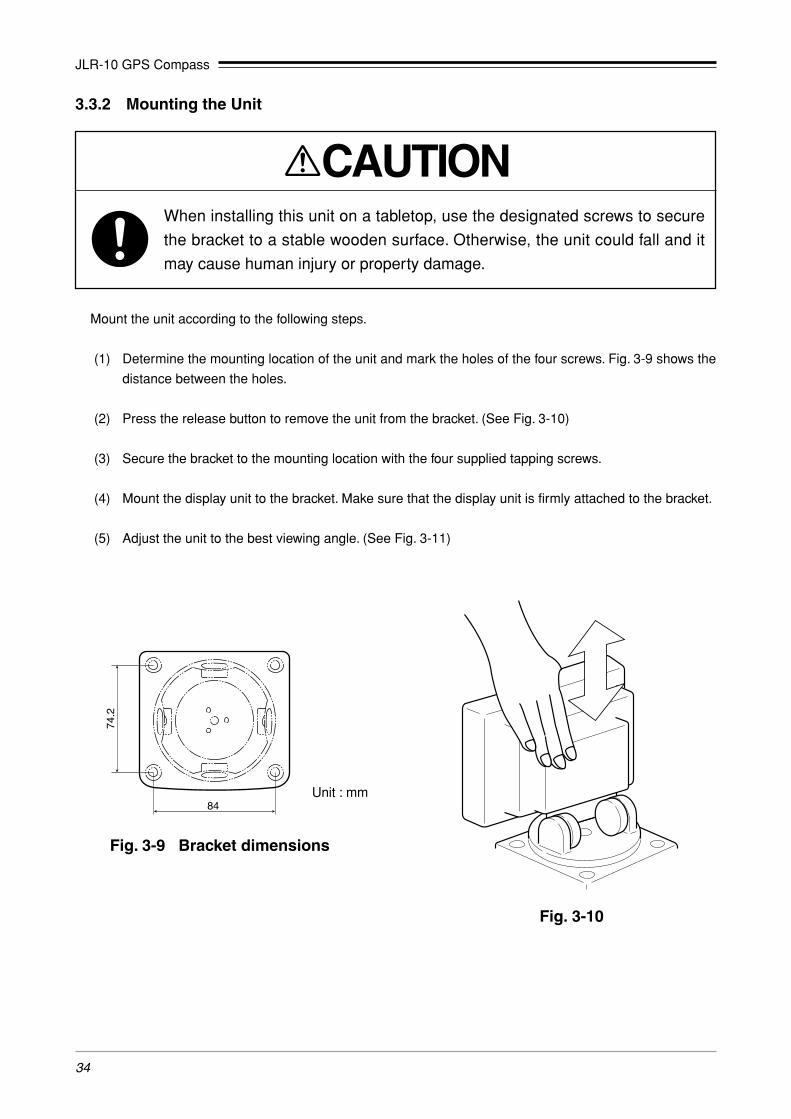
3.3.2 Mounting the Unit
Mount the unit according to the following steps.
(1) Determine the mounting location of the unit and mark the holes of the four screws. Fig. 3-9 shows the
distance between the holes.
(2) Press the release button to remove the unit from the bracket. (See Fig. 3-10)
(3) Secure the bracket to the mounting location with the four supplied tapping screws.
(4) Mount the display unit to the bracket. Make sure that the display unit is firmly attached to the bracket.
(5) Adjust the unit to the best viewing angle. (See Fig. 3-11)
84
74.2
Unit : mm
Fig. 3-9 Bracket dimensions
Fig. 3-10
CAUTIONWhen installing this unit on a tabletop, use the designated screws to secure
the bracket to a stable wooden surface. Otherwise, the unit could fall and it
may cause human injury or property damage.

JLR-10 GPS Compass
35
Fig. 3-11
Fig. 3-12
As shown below, an optional flush mount kit can be used to wallmount the navigator. For information on mounting, refer to the instructionmanual supplied with the kit.

JLR-10 GPS Compass
36
3.4 Connection of the Equipment
3.4.1 Connection of the Power Supply Cable
A 2m long DC power supply cable is included in the equipment, which needs to be securely inserted all the
way into the DC 12V/24V connector provided on the Processing Unit.
Connect the red cable to the plus terminal of the battery or power distribution panel and the black cable to the
minus terminal.
The equipment needs to be connected to the DC power supply source having the voltage range of DC 10.8V
to 31.2V. The power consumption of the equipment is 10 W or less with the Display Unit and the Antenna
connected to it. Use an AWG #17 cable or greater if the attached CFQ-6556 power supply cable (2m long)
needs to be extended.
Processing unit sideDC power supply source side
Black –
Red +
Fig. 3-13 Outline drawing of power supply cable connector
Fig. 3-14
2 1
Pin arrangement of DC12V/24V
connector on Processing Unit
Pin No. Remarks
1 GND
2 DC 12V/24V input

JLR-10 GPS Compass
37
3.4.2 Connection of the Grounding Line
The Processing Unit needs to be grounded to protect it from the static electricity and to avoid possible noise
generation. Connect the terminal “GND” provided on the Processing Unit to the nearest vessel frame with the
copper plate (25Wx2,000x0.3t) etc.
3.4.3 Connection of the Antenna Cable
To run the preamplifier that is incorporated in the antennas, DC +5V is applied to the antenna connectors
“ANT BOW” and “ANT STERN” of the Processing Unit (central conductor “+”). Check that the connector of the
antenna cable is not short circuited before connecting.
q Connect the cable with “BOW” indicated to “ANT BOW” of the Processing Unit.
w Connect the cable with “STERN” indicated to “ANT STERN” of the Processing Unit.
Fig. 3-15 Outline drawing of antenna cable connector

JLR-10 GPS Compass
38
3.4.4 Connection of the Display Unit Cable
See the description under the Section 2.3.2, “Rear Panel of the Display Unit” for the connector provided to
connect to the Processing Unit.
Keep the excessive the Processing Unit connection cable away from the Display Unit by a minimum of 30 cm after
connecting it. Failure to observe the instruction can cause interference to other radio equipment.
The Processing Unit supplies 12 VDC power to the Display Unit. After the Processing Unit is turned on the
Display Unit can be turned on. The Processing Unit receives information from the satellites and sends it to the
Display Unit.
(1) Securely insert the CFQ-6557 Display Unit cable plug into the “DISP” connector provided on the Pro-
cessing Unit.
Fig. 3-16 Outline drawing of display unit cable connector
Fig. 3-17
1 5
42
6
3
Pin arrangement of DISP
connector on Processing Unit
Pin No. Remarks
1 DC 12V output
2 Ground
3 Data common (Ground) TTL
4 Display data output TTL
5 Setting data input TTL
6 DGPS input TTL

JLR-10 GPS Compass
39
(2) Securely insert the CFQ-6557 Display Unit cable plug into the “GPS/DGPS” connector provided on the
rear panel of the Display Unit.
(3) Then, mount the suppression ferrite on the cable at a position closest to the GPS/DGPS connector to
eliminate any unwanted noise.
Fig. 3-18
Fig. 3-19
Suppression ferrite(E04SR301334 or equivalent)
Cable
1 5
42
6
3
Pin arrangement of GPS/DGPS
connector on Display Unit
Pin No. Remarks
1 DC 12V input
2 Ground
3 Data common (Ground) TTL
4 Display data input TTL
5 Processing Unit setting data output TTL
6 Open
JLR-10 GPS Compass
40
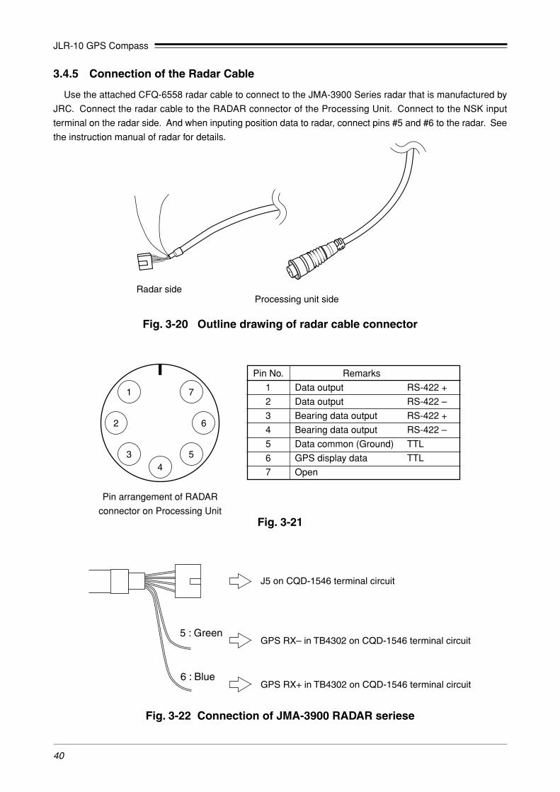
3.4.5 Connection of the Radar Cable
Use the attached CFQ-6558 radar cable to connect to the JMA-3900 Series radar that is manufactured by
JRC. Connect the radar cable to the RADAR connector of the Processing Unit. Connect to the NSK input
terminal on the radar side. And when inputing position data to radar, connect pins #5 and #6 to the radar. See
the instruction manual of radar for details.
Processing unit sideRadar side
Fig. 3-20 Outline drawing of radar cable connector
Fig. 3-21
4
2 6
3 5
1 7
Pin arrangement of RADAR
connector on Processing Unit
Pin No. Remarks
1 Data output RS-422 +
2 Data output RS-422 –
3 Bearing data output RS-422 +
4 Bearing data output RS-422 –
5 Data common (Ground) TTL
6 GPS display data TTL
7 Open
5 : Green
J5 on CQD-1546 terminal circuit
GPS RX– in TB4302 on CQD-1546 terminal circuit
GPS RX+ in TB4302 on CQD-1546 terminal circuit6 : Blue
Fig. 3-22 Connection of JMA-3900 RADAR seriese
JLR-10 GPS Compass
41
3.4.6 Confirmation after Installation
Confirm the installation condition. If the unit is connected properly, turn on the power.
When the screen is displayed in English, change the screen to another language if desired, according to the proce-
dure described in Section 4.3, “Selecting Display Language”.
See Section 4.6, “Basic Menu Selection Operations” for key operations to be used for menu selection setting on the display window.
q Turn on the power of the Processing Unit and then the Display Unit.
Processing unit : Turn on the "POWER" switch. The lamp is lit.
Display unit : Turn on the "PWR" switch.
w When a GPS satellite signal is received, the satellite count is increased and when fixing is completed
(calculation of latitude and longitude), the mode is automatically changed to the [HEADING] display mode.
When bearing calculation is not completed, the value display blinks.
(When the unit is delivered from the factory, the mode is set to a Cold Start mode so that about 3 minutes
are required for fixing.)
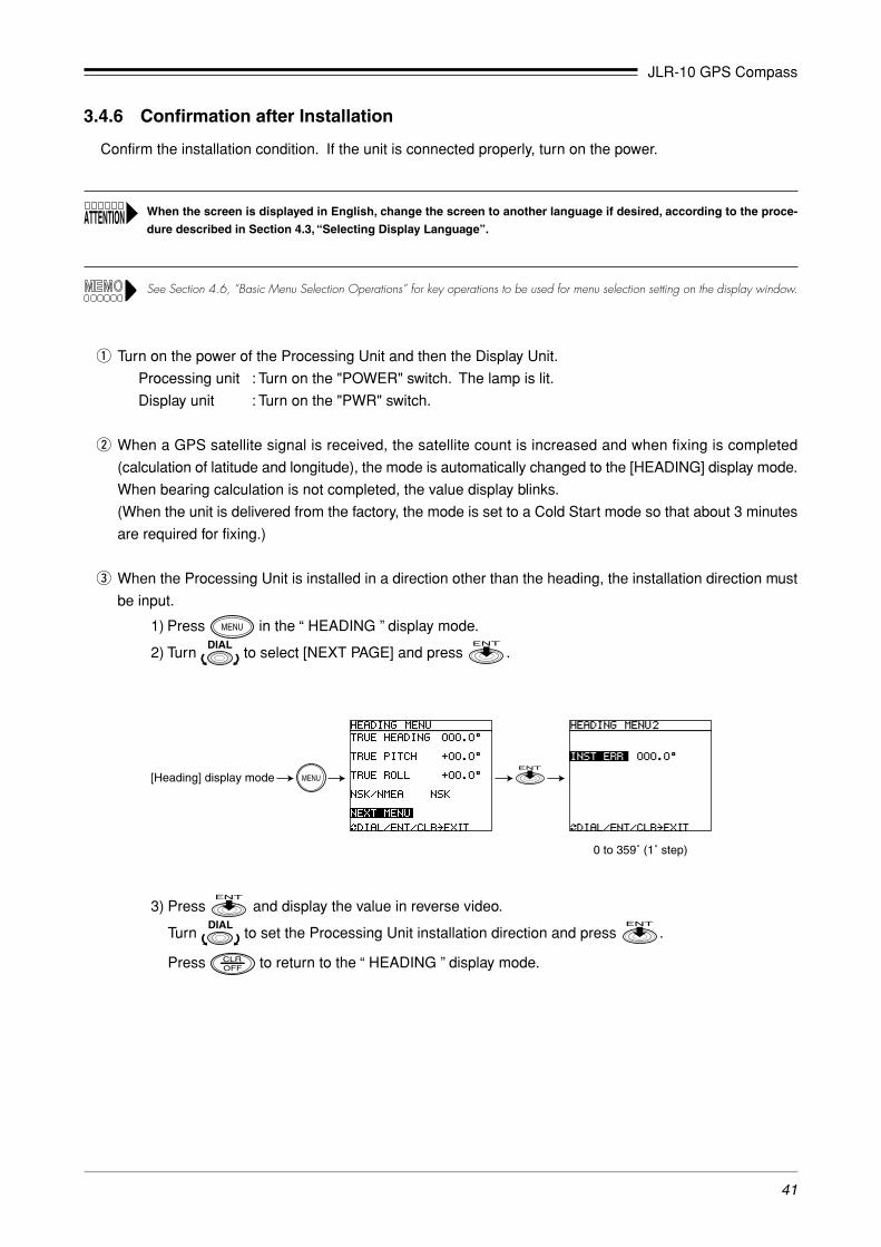
e When the Processing Unit is installed in a direction other than the heading, the installation direction must
be input.
1) Press in the “ HEADING ” display mode.
2) Turn to select [NEXT PAGE] and press .
[Heading] display mode
0 to 359˚ (1˚ step)
3) Press and display the value in reverse video.
Turn to set the Processing Unit installation direction and press .
Press to return to the “ HEADING ” display mode.

JLR-10 GPS Compass
42
r Check that the bearing is calculated correctly in the “ HEADING ” display mode.
Assume that the calculation is correct when the value blinking stops and no alarm is issued.
t When a true bearing is available by using a GPS compass, the antenna installation bearing can be set.
1) Press in the “ HEADING ” display mode.
2) Select [TRUE HEADING] and press .
3) Turn to set a true bearing and press .
The GPS compass outputs the true bearing by calculating the difference between its bearing and the bearing
that was set. Execute Master Reset to reset the bearing that was set.
When setting the bearing , be carefule of the following two points.
• After turning on the power or excuting Master Reset, set the bearing after it is first measured and more than 3
minutes pass. If the bearing is set within 3 minutes, error may become large.
• Set the bearing while the ship is relatively stable. Otherwise, the setting error may become large.
y If a fix is not completed after 20 minutes, check the receiving condition in the “ STATUS ” display mode.
1) Check the bearing alarm is not blinking.
When a digit between “2” and “6” is displayed, check that there is no obstruction that interferes with
radio waves near the antenna such as a pole, mast, building, or mountain. Alternatively, change
the antenna installation position or move the ship.
2) Check that the antenna alarm is not blinking.
Check the BOW antenna and STERN antenna. To switch the bow and stern, press .
When “O” is blinking, the connection is opened. Check if there is any unconnected connector or
cable rupture.
When “S” is blinking, short-circuit is assumed. Check if the cable is short circuited.
3) Check the satellite reception condition.
Check the bow receiver and stern receiver.
To switch the bow and stern, press .
Check that the satellite number, bearing angle, and elevation are displayed and that there are five
or more satellites of level 40 or higher. When the level is 0, check the installation status again.

JLR-10 GPS Compass
43
3.5 Connection of the Optional Equipment
3.5.1 Connection of the GPS Repecon
By connecting the NID2001 Repecon that is made available as an option, a repeater (90X) can be used.
Connect the GPS Repecon to the OPTION connector of the Processing Unit using the OPTION cable.
Use pins #3 and #4 of the OPTION connector.
The data format is NSK (the format for JRC radar). (The initial setting of the Processing Unit is “NSK”.)
See the instruction manual of GPS Repecon for details.
POWER FUSE2A
ANT BOW ANT STERN DISP
RADAR NMEA OPTION
GND DC12V/24V
Processing Unit
OPTION connector(Pin No.3 [Orange] and 4 [Yellow])
OPTION cableCFQ-6559
GPS Repecon
FUSE FUSE FUSE FUSE FUSE
POWER REPEARERCOMPASS
GYROCOMPASS
GPS
REPEATERCOMPASS
GYROCOMPASS
GPS
NAVIGATIONEQUIPMENT
DEC.
SYNCHRO ADJUSTNID2001INC.
LOCK
GPS-REPECONPOWER (3A) REPEATER
COMPASSNAVIGATIONEQUIPMENT
GYROCOMPASS
SYNCHROSYGNAL
Fig. 3-23
Fig. 3-24
4
2 8 6
3 5
1 7
Pin arrangement of OPTION
connector on Processing Unit
Pin No. Remarks
1 Open
2 Open
3 Bearing data output RS-422 +
4 Bearing data output RS-422 –
5 Data common (Ground)
6 Bearing data output TTL
7 Open
8 Open

JLR-10 GPS Compass
44
e Connect the synchronization signal from the gyro compass to the synchronization signal IN terminal.
R1 R2 S1Gyro signal IN
S3S2
RX+NSK
GRX–
R1 R2 S1Nautical instrument
S3S2R1 R2 S1Repeater
S3S2
R1 R2AC100V
Fig. 3-25 Arrangement of internal terminals
q Connect a AC 100V power to the terminals R1 and R2 of the "AC100V" terminal box.
w Connect the bearing data output #3 (Orange) and #4 (Yellow) of OPTION cable to RX+ and RX- terminals
of the NSK.
JLR-10 GPS Compass
45
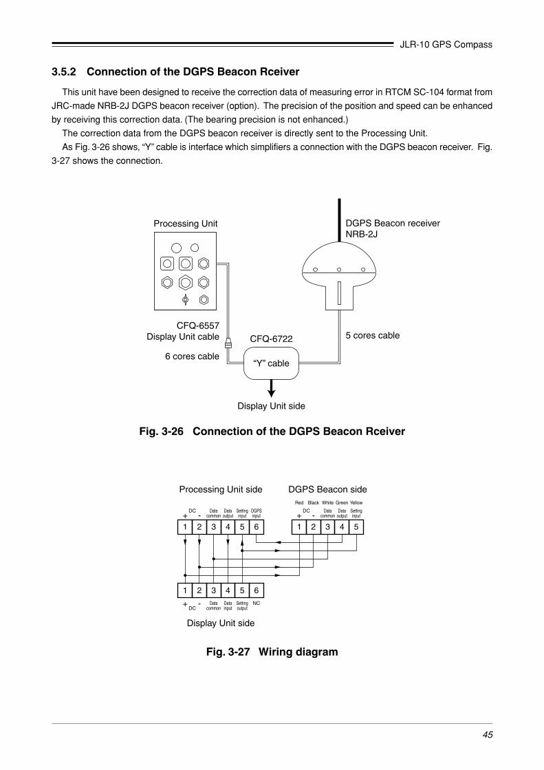
3.5.2 Connection of the DGPS Beacon Rceiver
This unit have been designed to receive the correction data of measuring error in RTCM SC-104 format from
JRC-made NRB-2J DGPS beacon receiver (option). The precision of the position and speed can be enhanced
by receiving this correction data. (The bearing precision is not enhanced.)
The correction data from the DGPS beacon receiver is directly sent to the Processing Unit.
As Fig. 3-26 shows, “Y” cable is interface which simplifiers a connection with the DGPS beacon receiver. Fig.
3-27 shows the connection.
Fig. 3-26 Connection of the DGPS Beacon Rceiver
DGPS Beacon receiverNRB-2J
“Y” cable
CFQ-6722
Display Unit side
Processing Unit
CFQ-6557Display Unit cable
6 cores cable
5 cores cable
1 2 3 4 5 6
1 2 3 4 5
1 2 3 4 5
DGPS Beacon side
Dataoutput
Datacommon-+
DC
DC
Settinginput
Datainput
Datacommon
-+ Settingoutput
6NC
DGPSinput
Dataoutput
Datacommon-+
Black White
Processing Unit side
Display Unit side
Green YellowRed
DC Settinginput
Fig. 3-27 Wiring diagram

JLR-10 GPS Compass
46
3.5.3 Connection of the DGPS Rceiver
This unit can output hight precision data of the position and speed that the DGPS receiver calculates to the
Display Unit or external equipments by connecting with the DGPS receiver (DGPS 212).
The measured data from the DGPS receiver is directly sent to the Processing Unit, and the Processing Unit
outputs this data.
As Fig. 3-28 shows, “Y” cable is interface which simplifiers a connection with the DGPS receiver. Fig. 3-29
shows the connection.
When the DGPS receiver is connected, not only the infomation of the bow side or stern side GPS receiver but also the information of theconnected DGPS receiver can be displayed.When [DGPS] is set in “Selected receiver”, this information is displayed.For information on how to switch selected receiver, see Section 4.5.8, “STATUS Display Mode”.
When the DGPS receiver is connected and selected receiver is set [DGPS], GNS sentence of navigation information
from the NMEA connector is not output.
If you output GNS sentences, set [BOW] or [STERN] in “Selected receiver”.
Fig. 3-28 Connection of the DGPS Rceiver
1 2 3 4 5 6
Dataoutput
Datacommon-+
DC
DC
Settinginput
1 2 3 4 5Datainput
Datacommon
-+ Settingoutput
6NC
DGPSinput
1 2 3 4 5
Dataoutput
Datacommon-+
Black White
DGPS receiver sideProcessing Unit side
Display Unit side
Green YellowRed
DC Settinginput
Fig. 3-29 Wiring diagram
“Y” cable
CFQ-6722
Display Unit side
Processing Unit
CFQ-6557Display Unit cable
6 cores cable
5 cores cable
DGPS rceiver

JLR-10 GPS Compass
47
3.5.4 Connection of the Other Equipment
Use the NMEA connector for connecting various navigation equipment devices.
Use the optional NMEA cable, CFQ-6560.
Fig. 3-30
1
543
121110
6 7 8 9
2
13 14
Pin arrangement of NMEA
connector on Processing Unit
Pin No. Remarks
1 NMEA0183 Navigation data RS-422 +
2 NMEA0183 Navigation data RS-422 –
3 NMEA0183 HDT RS-422 +
4 NMEA0183 HDT RS-422 –
5 NMEA0183 ROT RS-422 +
6 NMEA0183 ROT RS-422 –
7 Alarm (Contact signal) +
8 Alarm (Contact signal) –
9 Log pulse (Contact signal) +
10 Log pulse (Contact signal) –
11 NMEA0183 Display data RS-422 +
12 NMEA0183 Display data RS-422 –
13 Open
14 Open
JLR-10 GPS Compass
48
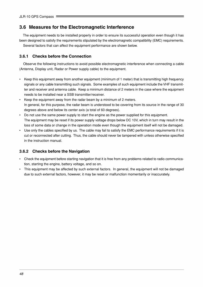
3.6 Measures for the Electromagnetic Interference
The equipment needs to be installed properly in order to ensure its successful operation even though it has
been designed to satisfy the requirements stipulated by the electromagnetic compatibility (EMC) requirements.
Several factors that can affect the equipment performance are shown below.
3.6.1 Checks before the Connection
Observe the following instructions to avoid possible electromagnetic interference when connecting a cable
(Antenna, Display unit, Radar or Power supply cable) to the equipment.
• Keep this equipment away from another equipment (minimum of 1 meter) that is transmitting high frequency
signals or any cable transmitting such signals. Some examples of such equipment include the VHF transmit-
ter and receiver and antenna cable. Keep a minimum distance of 2 meters in the case where the equipment
needs to be installed near a SSB transmitter/receiver.
• Keep the equipment away from the radar beam by a minimum of 2 meters.
In general, for this purpose, the radar beam is understood to be covering from its source in the range of 30
degrees above and below its center axis (a total of 60 degrees).
• Do not use the same power supply to start the engine as the power supplied for this equipment.
The equipment may be reset if its power supply voltage drops below DC 10V, which in turn may result in the
loss of some data or change in the operation mode even though the equipment itself will not be damaged.
• Use only the cables specified by us. The cable may fail to satisfy the EMC performance requirements if it is
cut or reconnected after cutting. Thus, the cable should never be tampered with unless otherwise specified
in the instruction manual.
3.6.2 Checks before the Navigation
• Check the equipment before starting navigation that it is free from any problems related to radio communica-
tion, starting the engine, battery voltage, and so on.
• This equipment may be affected by such external factors. In general, the equipment will not be damaged
due to such external factors, however, it may be reset or malfunction momentarily or inaccurately.

JLR-10 GPS Compass
49
4. Operation
4.1 Overview
When the setup operations described in Chapter 3 have been completed, turn on the power at the order of the
Processing Unit and the Display Unit to start operation. This chapter describes the basic flow of operations. The
bold line boxes indicate user operations.
Power on
Power down
Self-test
GPS status information display
Position fixing completed
“ HEADING ” display mode
Display language selection
Contrast and backlight adjustment
Settings
Waypoint settingRoute plan setting
Direct route setting or selecting route plan number
Switching navigation plans
Initial position bearing measurment after a master reset takes about 5 minutes. Subsequent position fixing after power on takes about 3 minute.This display mode is always shown when first turning on.
Select from seven languages; the default language is English. Set to a desired language. (See Section 4.3.)
Adjust LCD contrast and LCD/keyboard backlighting as required.(Use .) (See Section 4.7.)
(See Section 4.2.)
You can customize the navigation system to your own needs by making settings in the various display modes.
• Set fishing points, harbors or other waypoints (up to 499 can be set).A single press of the key can turn the current position to a waypoint. (See Section 4.18.)
• Also set the route plan. A total of 20 route plans with up to 199 waypoints can be set. (See Section 4.19.)
• Press and select a waypoint registered in memory to steer towards this waypoint. (See Section 4.10.)
• Select a route plan to navigate according to this plan. (See Section 4.11.)
• An alarm can be set to go off when the ship reaches a waypoint.
Go between the five main display modes: “ HEADING ”, “ POSITION ”,“ NAVIGATION ”, “ CDI ” and “ PLOT ” to view different navigation information. (See Section 4.4.)
All current settings are saved. (When the power is turned off, the internal batteries in the Processing Unit and the Display Unit will back up the memory. The life of battery is more than five years.)
For information on messages output during operation, see Appendix 3-A, “Message List”.

JLR-10 GPS Compass
50
4.2 Turning the Unit ON/OFF
Processing Unit
• Press the POWER switch (the lamp light up) to turn on the Processing Unit.
• Press this switch again (the lamp put out the light) to turn off the Processing Unit.
Display Unit
• Press to turn on the Display unit.
• Press and simultaneously to turn off the Display unit.
Even if the power of the Display Unit is turned off, the power of the Processing Unit is not turned off.
� Display shown when the unit is turned on
When the Display unit is turned on after turning on the Processing Unit, the displays are shown in the order
given below: When position fixing is completed, the “ HEADING ” display is shown.
• Position bearing measurment the first time the unit is used or after a master reset takes about 5 minutes. (Subsequent position fixingtakes about 3 minute.)
• For information on data error display, see Appendix 3-A, “Message List”.
� Master reset
This unit is equipped with the following reset functions. For example, if the internal battery or the ROM IC is
replaced, a master reset would have to be performed.
When resetting the unit, perform Initializing GPS as described in Section 4.20.2 when correcting for local time.
1. Soft reset
This reset clears all data except registered waypoints and route plans.
• Key operated soft reset
Press while holding down .
• Menu select soft reset
See Section 4.22, “Performing Master Reset.”
[Self-test result][Version]GPS status information
After position fixing

JLR-10 GPS Compass
51
2. Hard reset
This reset clears all data including registered waypoints and route plans.
• Key operated hard reset
Press while holding down .
• Menu select hard reset
See Section 4.22, “Performing Master Reset.”
4.3 Selecting Display Language
The display language is set to English at the factory before shipment and reverts to this setting after a master
reset. Use the following steps to set it to any desired language. One of the following seven languages can be set.
LANGUAGE: English (default)/Deutsch/Francais/Español/Norsk/Italiano/ニホンゴニホンゴニホンゴニホンゴニホンゴ
� Display example
(1) After position fixing, the “ HEADING ” display mode appears.
Press to display the Select Mode.
(2) Turn to select “ NAVIGATION ” and press to confirm it.
This action displays the “ NAVIGATION ” display mode.
(3) Press to display the “ NAVIGATION MENU ”.
(4) Turn to select “ LANGUAGE ” and press .
“ ENGLISH ” is now highlighted.
(5) Turn to select desired language and press .
Check that the selected language is displayed.
(6) Press to return to “ NAVIGATION ” display mode.
[Select Mode] [Navigation] [Navigation Menu]
JLR-10 GPS Compass
52
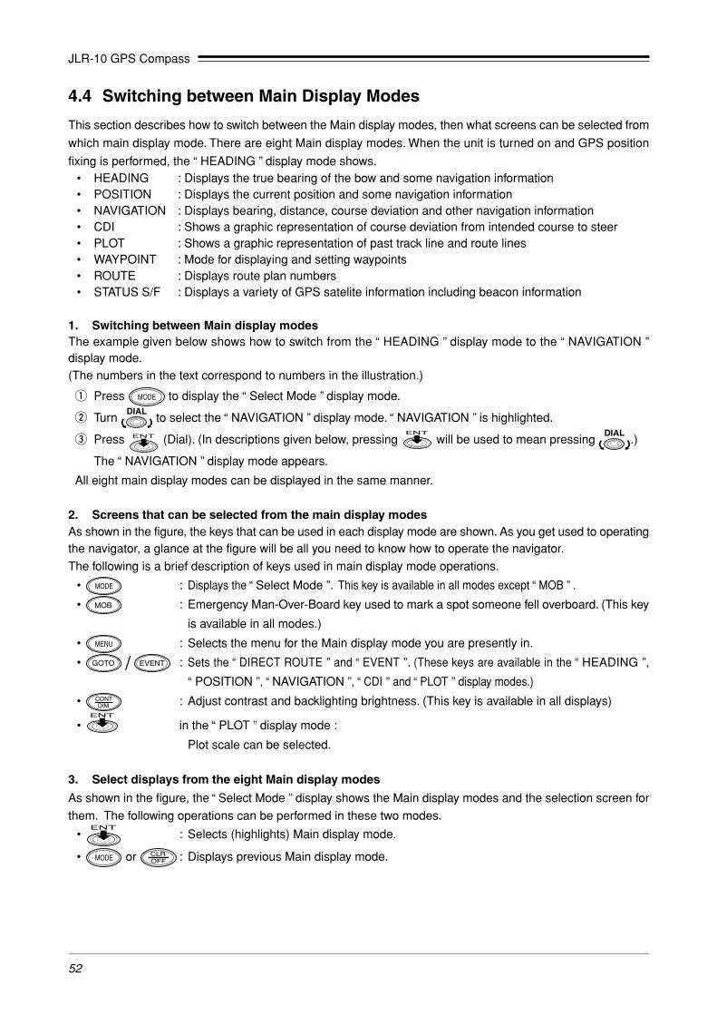
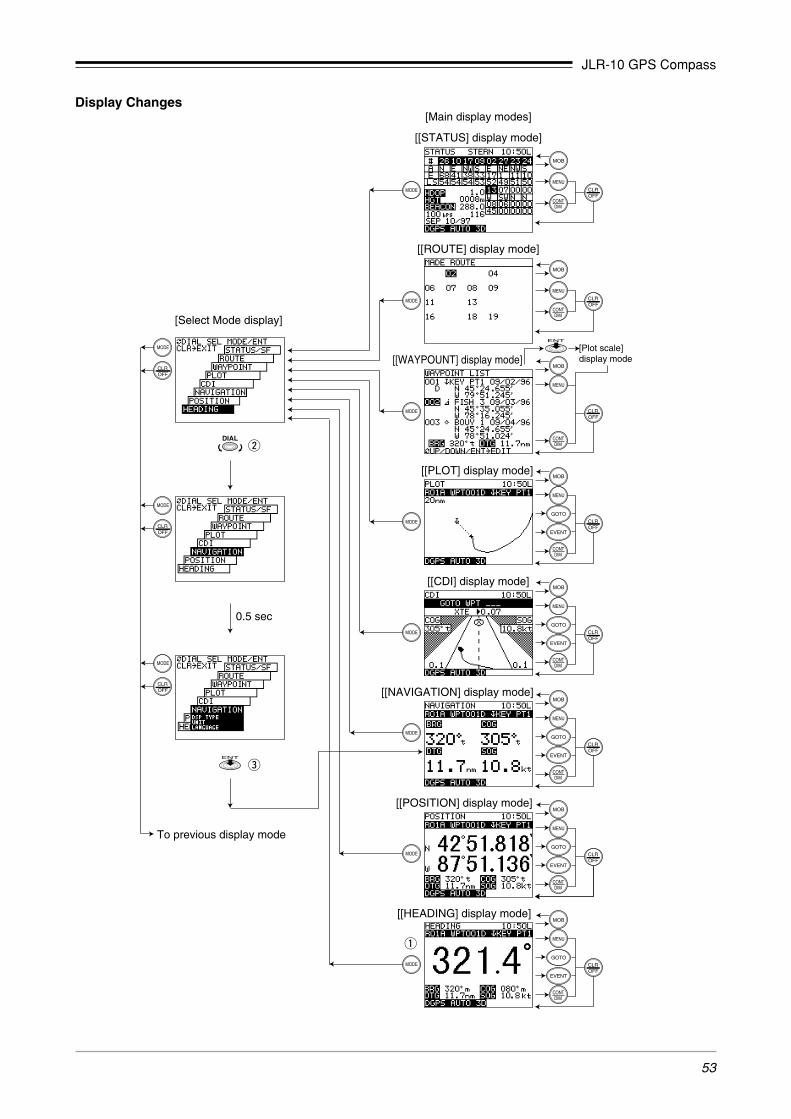
4.4 Switching between Main Display Modes
This section describes how to switch between the Main display modes, then what screens can be selected from
which main display mode. There are eight Main display modes. When the unit is turned on and GPS position
fixing is performed, the “ HEADING ” display mode shows.• HEADING : Displays the true bearing of the bow and some navigation information• POSITION : Displays the current position and some navigation information• NAVIGATION : Displays bearing, distance, course deviation and other navigation information• CDI : Shows a graphic representation of course deviation from intended course to steer• PLOT : Shows a graphic representation of past track line and route lines• WAYPOINT : Mode for displaying and setting waypoints• ROUTE : Displays route plan numbers• STATUS S/F : Displays a variety of GPS satelite information including beacon information
1. Switching between Main display modesThe example given below shows how to switch from the “ HEADING ” display mode to the “ NAVIGATION ”display mode.(The numbers in the text correspond to numbers in the illustration.)
q Press to display the “ Select Mode ” display mode.
w Turn to select the “ NAVIGATION ” display mode. “ NAVIGATION ” is highlighted.
e Press (Dial). (In descriptions given below, pressing will be used to mean pressing .)
The “ NAVIGATION ” display mode appears.
All eight main display modes can be displayed in the same manner.
2. Screens that can be selected from the main display modesAs shown in the figure, the keys that can be used in each display mode are shown. As you get used to operatingthe navigator, a glance at the figure will be all you need to know how to operate the navigator.
The following is a brief description of keys used in main display mode operations.
• : Displays the “ Select Mode ”. This key is available in all modes except “ MOB ” .
• : Emergency Man-Over-Board key used to mark a spot someone fell overboard. (This key
is available in all modes.)
• : Selects the menu for the Main display mode you are presently in.
• / : Sets the “ DIRECT ROUTE ” and “ EVENT ”. (These keys are available in the “ HEADING ”,
“ POSITION ”, “ NAVIGATION ”, “ CDI ” and “ PLOT ” display modes.)
• : Adjust contrast and backlighting brightness. (This key is available in all displays)
• in the “ PLOT ” display mode :
Plot scale can be selected.
3. Select displays from the eight Main display modes
As shown in the figure, the “ Select Mode ” display shows the Main display modes and the selection screen for
them. The following operations can be performed in these two modes.
• : Selects (highlights) Main display mode.
• or : Displays previous Main display mode.
JLR-10 GPS Compass
53
Display Changes
0.5 sec
[Select Mode display]
To previous display mode
[[STATUS] display mode]
[[ROUTE] display mode]
[[WAYPOUNT] display mode][Plot scale] display mode
[[PLOT] display mode]
[[CDI] display mode]
[[NAVIGATION] display mode]
[[POSITION] display mode]
[Main display modes]
[[HEADING] display mode]
w
e
q

JLR-10 GPS Compass
54
4.5 Main Display Modes
This section describes how to interpret the eight main display modes.
• Display modes where waypoints and route plans have already been set are used in the examples.
• For information on items shared by each display mode, see Section 4.5.1, “HEADING Display Mode.”
4.5.1 HEADING Display Mode
This display mode shows the true bearing of the bow and navigation information. The following items are
displayed in the “ HEADING ” display mode.
The data displayed in this display mode can be changed in the menus.
q Display Mode name
Indicates that the “ HEADING ” display mode is shown.
w Time (hour: min)
Displays the current time derived from GPS data.
The character L (default value) indicates local time and U indicates universal time (GMT).
(For more information, see Section 4.16, “Setting CDI Range and Display Time Format.”)
e Route plan number
Displays the currently selected route plan number (R01 to R20).
The symbol A indicates that route legs are automatically stepped. No symbol is displayed for manual step.
(See Section 4.11, “Navigation according to Route Plans.”)
The message “WPT NO DEST” is showed when no waypoint has been selected in a route plan or by direct
route selection.
r Waypoint number
Displays the number of currently selected waypoint for destination.
Example: WPT 001 WPT: waypoint
001: waypoint number
When waypoints are registered through an key pressing, a “D” or “G” is appended to the waypoint
number to indicate the position fixing of GPS or DGPS, respectively.
[Heading] display mode
q Display mode name
e Route plan number
y Heading
u Bearing alarm
i Navigationinformation
o Position fix status !0 Navigation alarm
r Waypoint number w Time
t Waypoint name

JLR-10 GPS Compass
55
t Waypoint name
Displays the name registered for a waypoint.
y Heading
Displays the current heading in true bearing.
u Bearing alarm
The following bearing alarms can be displayed.
• 2 : Fixing calculation disabled (the case of receiving from five or more satellites)
• 3 : Fixing calculation un-completing
• 4 : Common reception satellites for two antennas (BOW, STERN) are three or less
• 6 : Fixing calculation disabled (the case of receiving from four satellites)
• 7 : Aux. sensor is failure (the bearing of heading)
• 8 : Aux. sensor is failure (the bearing of roll)
• 9 : Aux. sensor is failure (the bearing of pich)
i Navigation information
Displays one of the following data - selectable
1. BRG/DTG/COG/SOG (default)
2. BRG/DTG/XTE/TTG
3. CMG/VTD/COG/SOG
4. BRG/VAH/COG/SOG
• BRG : Bearing to destination (unit: °)• DTG : Distance to go to destination
Unit : nautical miles (nm default, sm, km available)
• COG : Course over ground (unit: °)• SOG : Average speed of ship (speed over ground )
Unit : kt (knots) (default) (when the distance unit is nm), mh (when the distance
unit is sm), kh (km/hour) (when the distance unit is km)
• XTE : Cross track error. Deviation from course and direction to steer (unit: 0.01 nauti-
cal miles)
Steering required to return to the planned course is indicated by L (left) and R
(right).
• TTG : Time to go until arrival at destination (unit: hour, minute)
• CMG : Bearing (unit: °) to the current position as viewed from the origin
• VTD : Velocity toward destination
Unit : kt (knots) (default) (when the distance unit is nm), mh (when the distance
unit is sm), kh (km/hour) (when the distance unit is km)
• VAH : Velocity toward heading
Unit : kt (knots) (default) (when the distance unit is nm), mh (when the distance
unit is sm), kh (km/hour) (when the distance unit is km)
(See Section 4.15, “Setting Navigation Display Modes and Units.”)
A “t” after the figure for BRG, COG and CMG indicates true bearing, while “m” indicates that magnetic compass
correction has been made.)

JLR-10 GPS Compass
56
o Position fix status
This position is displaying the Processing Unit (or DGPS receiver) position fix status.
When GPS reception is stopped or when a problem has occurred in position fixing, HDOP or NO FIX alarm
is displayed.
Be careful! The accuracy of heading lowers when the alarm is displayed.
For information on alarms, see Appendix 3-A, “Message List.”
• When Processing Unit (or DGPS receiver) calculate the position after receiving at last one position fix, the message
“ NO FIX ” is displayed and the alarm sounds. The alarm sounds can be canceled by pressing .
• The alarm sounds once when Processing Unit (or DGPS receiver) switches from DGPS position fixing to GPS posi-
tion fixing. (When DGPS alarm is set.)
!0 Navigation alarm
Displays alarms if selected.
• ARV (arrival alarm)
The alarm sounds and the characters ARV flash when the ship comes inside a set distance from
a waypoint.
• ANC (anchor alarm)
When the ship drifts beyond the set distance from a waypoint, the alarm sounds and the charac-
ters ANC flash.
• XTE (off-course alarm)
When the ship strays off course by more than the set distance, the alarm sounds and the charac-
ters XTE flash.
(See Section 4.9, “Setting Alarms (Arrival/Anchor/Off-course/DGPS)”.)
� Canceling alarms
• Press to cancel the alarm sounds.
• To disable the alarm display, set 0.00 as the alarm range. (See Section 4.9, “Setting Alarms (Arrival/
Anchor/Off-course/DGPS)”.)

JLR-10 GPS Compass
57
The operation of each alarm is described in the figures shown below.
Set distance
Waypoint
Alarm range
Fig. 4-2
ANC (anchor alarm)
The alarm goes off when the ship goes be-
yond a set distance.
Fig. 4-1
ARV (arrival alarm)
The alarm goes off when the ship comes in-
side a set distance of a waypoint.
Alarm range
WaypointPosition
Set distance
Fig. 4-3
XTE (Off-course alarm)
The alarm goes off when the ship strays more
than a set distance beyond its intended course.
Waypoint
Set distance
Planned course
Origin
Alarm range

JLR-10 GPS Compass
58
Navigation information
“ NAVIGATION ” display mode is the some type of information indicated in i, “Navigation information” de-
scribed in Section 4.5.1, “HEADING Display Mode.” For details, see Section 4.5.1, “HEADING Display Mode.”
1. BRG/DTG/COG/SOG (default)
2. BRG/DTG/XTE/TTG
3. CMG/VTD/COG/SOG
4. BRG/VAH/COG/SOG
The above display mode appears when 1. is selected.
q Current position
Latitude and longitude are displayed.
For details, see Section 4.5.1, “HEADING Display Mode”
4.5.3 NAVIGATION Display Mode
This display mode shows the following navigation information.
The type of data displayed in this display mode can be selected in the menus.
4.5.2 POSITION Display Mode
This display mode shows current position and navigation information. The following items are displayed in the
“ POSITION ” display mode.
The data displayed in this display mode can be changed in the menus.
[Latitude/Longitude] display mode
q Current position

JLR-10 GPS Compass
59
4.5.4 CDI Display Mode
This display mode offers a graphic representation of course deviation. It displays the data shown below.
The data displayed in this display mode can be changed in the menus.
q Course deviation
Shows the deviation from the set course and the direction to steer. (unit: 0.01 nm). The ( ) symbol indicates
that the ship should be turned left and the ( ) symbol indicates that it should turn right to return to the set
course. When the display indicates a deviation of 0.00, the ship will reach its destination by the shortest
route.
w COG
Course over ground (unit: °)“t” indicates true bearing and “m” indicates magnetic compass corrected value.
e SOG
Displays the average speed (speed over ground) in kt (knots), mh, kh
r CDI Range
Displays 0.1 (default), 0.3, 0.5 nm depending on setting.
(See Section 4.16, “Setting CDI Range and Display Time Format.”)
Waypoint symbol
Ship symbol
Track line
q Course deviation
e SOGw COG
r Range of CDI
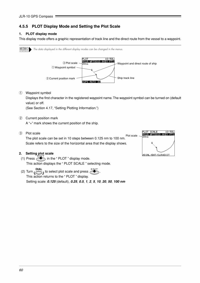
JLR-10 GPS Compass
60
4.5.5 PLOT Display Mode and Setting the Plot Scale
1. PLOT display mode
This display mode offers a graphic representation of track line and the direct route from the vessel to a waypoint.
The data displayed in the different display modes can be changed in the menus.
q Waypoint symbol
Displays the first character in the registered waypoint name. The waypoint symbol can be turned on (default
value) or off.
(See Section 4.17, “Setting Plotting Information.”)
w Current position mark
A “+” mark shows the current position of the ship.
e Plot scale
The plot scale can be set in 10 steps between 0.125 nm to 100 nm.
Scale refers to the size of the horizontal area that the display shows.
2. Setting plot scale
(1) Press in the “ PLOT ” display mode.
This action displays the “ PLOT SCALE ” selecting mode.
(2) Turn to select plot scale and press .
This action returns to the “ PLOT ” display.
Setting scale: 0.125 (default), 0.25, 0.5, 1, 2, 5, 10, 20, 50, 100 nm
Plot scale
Waypoint and direct route of ship
Ship track line
e Plot scale
q Waypoint symbol
w Current position mark
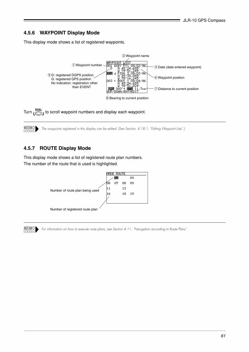
JLR-10 GPS Compass
61
4.5.6 WAYPOINT Display Mode
This display mode shows a list of registered waypoints.
Turn to scroll waypoint numbers and display each waypoint.
The waypoints registered in this display can be edited. (See Section, 4.18.1, “Editing Waypoint Lists”.)
4.5.7 ROUTE Display Mode
This display mode shows a list of registered route plan numbers.
The number of the route that is used is highlighted.
Number of route plan being used
Number of registered route plan
y Bearing to current position
w Waypoint name
q Waypoint number e Date (date entered waypoint)
r Waypoint position
u Distance to current position
t D: registered DGPS positionG: registered GPS positionNo indication: registration other
than EVENT
For information on how to execute route plans, see Section 4.11, “Navigation according to Route Plans”.

JLR-10 GPS Compass
62
4.5.8 STATUS Display Mode
The “ STATUS ” display mode shows all relevant satellite data.
q Satellite number
Displays numbers for the receiving satellites (12 of 01 to 32)
w Selected receiver
Displays whether information of the GPS receiver on the BOW side or the STERN side is displayed.
Press the dial ( ) to switch.
(When the DGPS receiver is connected with the Processing Unit, information (DGPS) of the DGPS re-
ceiver can be also displayed.)
e Azimuth angle
Displays the azimuth angle: N, NE, E, SE, S, SW, W, NW
r Elevation angle
Displays the elevation angle to each satellite.
t Receiving level
Displays the receiving level of each satellite. The greater the number, the higher the level is.
y Antenna alarm
Displays the antenna status.
• No display : Normal
• O : Open (No antenna is connected)
• S : Short (Antenna fault)
q Satellite number
u HDOP value
w Selected receiver
!1 Bearing alarm!0 Date
o Beacon status
t Receiving level
y Antenna alarm
r Elevation angle
e Azimuth angle
i Antenna height

JLR-10 GPS Compass
63
Satellites
A poor geometrical shape produces a
high HDOP level
A good geometrical shape produces a
low HDOP level
u HDOP value
Indicates HDOP value. Position becomes more accurate as the HDOP value decreases. When the HDOP
value exceeds 4, the HDOP indicator flashes to notify that the positioning accuracy is poor.
Tip HDOP levelA standard for assessing accuracy of position fixing. HDOP is based on the shape formed by the positions of satellites and the receiver;a good shape yields a low HDOP level and an accurate position fix value. A poor shape produces a high HDOP level and aninaccurate position value.
Fig. 4-4
i Antenna height
In 3D mode, the height of the Antenna obtained from position fixing is displayed.
Initial value are displayed when initialization is performed in 2D mode. (For details, see Section 4.20.2,
“Initializing GPS”). Initial values or the height obtained in previous 3D measurements are displayed in an
automatic mode.
o Beacon status
Displays the frequency, Baud rate and RSSI of DGPS beacon receiving signal.
RSSI: Receiving Signal Strength Indication
!0 Date
Displays date derived from position fix. (month/day/year)
!1 Heading alarm
Displays the heading calculation status or failure status of aux. sensor.
• No display : Normal
• 1 : Common reception satellites for two antennas (BOW, STERN) are four
• 2 : Heading calculation disabled (the case of receiving from five or more satellites)
• 3 : Heading calculation un-completing
• 4 : Common reception satellites for two antennas (BOW, STERN) are three or less
• 6 : Heading calculation disabled (the case of receiving from four satellites)
• 7 : Aux. sensor is failure (the bearing of heading)
• 8 : Aux. sensor is failure (the bearing of roll)
• 9 : Aux. sensor is failure (the bearing of pich)

JLR-10 GPS Compass
64
4.6 Basic Menu Selection Operations
The use of the has already been described in Sections 4.3, “Selecting Display Language” and 4.4,
“Switching between Main Display Modes.” This section will describe menu selections in detail.
The can be turned and pressed to select and confirm selected menus. Familiarize yourself with it and
you will be able to speedily select menus and confirm selections.
Read through this section carefully since what follows assumes a knowledge of what is described here.
�Keys used to select and set menus
• Turn : selects menu or menu items.
• Press (Press is used to mean press ): Menus and menu items that have been selected
by turning. are entered.
• Press :
- When pressed before a menu item has been set or entered, it cancels that selection and returns you to
the previous menu.
- When pressed after a menu item has been set or entered, it returns you to the previous menu.
• The next menu item to be selected is highlighted first then a comfirmed by puressing ( ).
Thus select and confirm items as they are highlighted to complete all the settings in a menu.
• Brief key instructions are given along the bottom of the screen to help you with entries.
Example: (DIAL/ENT/CLR ➝ EXIT) in the figure below means: Turn to select /press to confirm/press toreturn to previous menu).
� Operation examples
Detailed descriptions for setting in position correction menu in the [POSITION MENU].
Press in the “ POSITION ” display mode to display this menu.
[Position] display mode
Menu Selection item
Select All(Items cannot be displayed due to lack of space appear when selected.)
N 00.000' W 00.000'
S E

JLR-10 GPS Compass
65
Position Correction (latitude, longitude) menu setting
(1) Turn in the “ POSITION MENU ” display and press to select the [POS CORR] menu. [POS
CORR] is highlighted and the currently set value is displayed.
(2) Press to confirm [POS CORR].
The next item, [N] is highlighted.
(3) If [N] is the selection you wish to make, press . If you wish to select [S], turn to select [S] and
press to confirm the selection.
[00] is now highlighted.
(4) Turn to select the desired value and press to confirm the selection.
[000] is highlighted.
(5) Turn to select the desired value and press to confirm the selection. This action corrects the
latitude setting.
The next item to be set, [W] is highlighted.
(6) Repeat steps (3) to (5) to set longitude.
The [POS CORR] menu is displayed and [POS CORR] is highlighted.
(7) Press to return to the previous display.
• Use the key to amend number entries during settings.
Example: Amending a number entry made in step (3) above
When [00] has been confirmed, [000] is highlighted. Before confirming [000], press .
This action causes [00] to be highlighted and allows you to amend the [00] setting.
• Turning rapidly, changes the figures at high speed.

JLR-10 GPS Compass
66
4.7 Adjusting Contrast and Backlighting
This function adjusts contrast and backlighting in all screen displays.
(1) Press .
This action displays the screen for changing the contrast and backlighting.
(2) Turn to select the desired contrast.
Range of contrast selection: 00 to 15 (default value: 07)
(3) Press . Each press of the key toggles the setting between High and Low.
Backlight setting: HI/LOW (default)
(4) Press or wait for 5 seconds to return to the previous display mode.
4.8 Setting the Heading
When the power supply to the Processing Unit is switched ON, the position fixing will be started automatically,
and the heading will be calculated in about three minutes.
For information on entry operations given below, see Section 4.6, "Basic Menu Selection Operations"
4.8.1 Manually Setting the Heading
Normally, initial settings need not be made because the true heading is displayed after position fixing.
However, if the heading is already known using a gyro compass etc., and has to be matched with that heading,
it is possible to set the heading manually.
Do not set the pitch or roll, only the heading, because doing so may cause errors in the heading.
� Display example
(1) Press in the “ HEADING ” display mode.
This action displays “ HEADING MENU ”.
(2) Turn to select [TRUE HEADING] and press .
[Heading] display mode

JLR-10 GPS Compass
67
(3) Turn and set the heading orientation to a correct heading (such as the orientation indicated by a gyro
compass, etc.,) and press .
Set value range: 0.0 to 359.9˚.
When setting the bearing , be carefule of the following two points.
• After turning on the power or excuting Master Reset, set the bearing after it is first measured and more than 3
minutes pass. If the bearing is set within 3 minutes, error may become large.
• Set the bearing while the ship is relatively stable. Otherwise, the setting error may become large.
4.8.2 Selecting the Output Format of Heading Data
It is possible to select the heading data format of the output made to external devices, depending on the
application at hand.
(1) Press in the “ HEADING ” display mode.
This action displays “ HEADING MENU ”.
(2) Turn to select [NSK / NMEA] and press .
(3) Turn to select one of the following and press .
• NSK (defauit) :Data output format for the Radars manufactured by JRC.
• NMEA :HDT Sentence conforming to the NMEA0183 format.
4.8.3 Setting the Installation Direction of Processing Unit
When the Processing Unit is installed in a direction of heading, it is not necessary to input the installation direction.
When the Processing Unit is installed in a direction other than the heading, the installation direction must be
input.
(1) Press in the “ HEADING ” display mode.
(2) Turn to select [NEXT PAGE] and press .
(3) Press and display the value in reverse video.
Turn to set the Processing Unit installation direction and press .
Press to return to the “ HEADING ” display mode.
[Heading] display mode
0 to 359˚ (1˚ step)

JLR-10 GPS Compass
68
4.9 Setting Alarms
(Arrival/Anchor/Off-course/DGPS)
The navigator is provided with four types of alarms that can be set to inform you of important changes during
navigation.
Note that set alarms will go off whether you have selected a route plan or when you use the function
(see Section 4.10, “Navigation Using Direct Route [GOTO].” ).
Before reading the following sections, read Section 4.6, “Basic Menu Selection Operations.”
1. Selecting displays
(1) Press in the [ROUTE] display mode.
(2) Turn to select [Alarm] and press . This action displays the “ Alarm ” setting mode.
(3) To return to the [ROUTE] display mode, press twice.
� Display example
[Route] display mode
2. Setting
1) Arrival alarm
The arrival alarm can be set to alert you when you are
within a specified distance from your waypoint. The ar-
rival alarm can be set within a range of 0.00 to 9.99 nm.
• A setting of 0.00 turns off the alarm.
• This alarm is also valid in direct route navigation.
• When following a route plan, the arrival alarm selected
in setting up the route plan takes priority. (See Section,
4.11, “Navigation according to Route Plans.”)
Alarm range
WaypointPosition
Set distance
Fig. 4-5
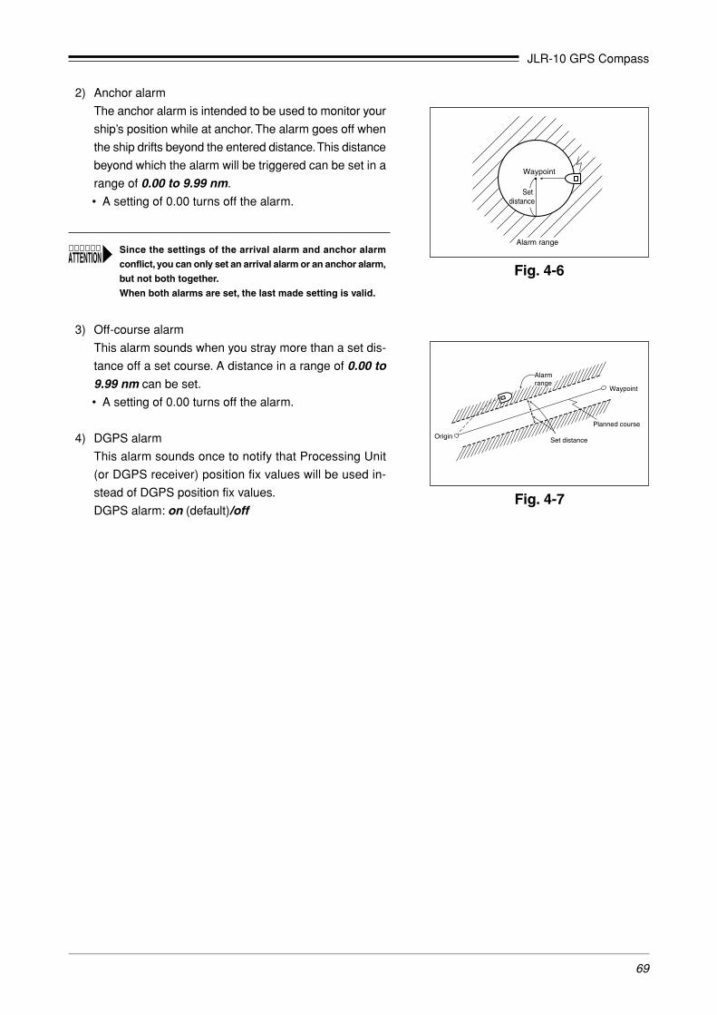
JLR-10 GPS Compass
69
2) Anchor alarm
The anchor alarm is intended to be used to monitor your
ship’s position while at anchor. The alarm goes off when
the ship drifts beyond the entered distance. This distance
beyond which the alarm will be triggered can be set in a
range of 0.00 to 9.99 nm.
• A setting of 0.00 turns off the alarm.
Since the settings of the arrival alarm and anchor alarm
conflict, you can only set an arrival alarm or an anchor alarm,
but not both together.
When both alarms are set, the last made setting is valid.
3) Off-course alarm
This alarm sounds when you stray more than a set dis-
tance off a set course. A distance in a range of 0.00 to9.99 nm can be set.
• A setting of 0.00 turns off the alarm.
4) DGPS alarm
This alarm sounds once to notify that Processing Unit
(or DGPS receiver) position fix values will be used in-
stead of DGPS position fix values.
DGPS alarm: on (default)/off
Set distance
Waypoint
Alarm range
Waypoint
Set distance
Planned course
Origin
Alarm range
Fig. 4-7
Fig. 4-6

JLR-10 GPS Compass
70
4.10 Navigation Using Direct Route [GOTO]
A registered waypoint number can be selected as a direct destination by pressing and entering a waypoint
number. The function is available in the following five main display modes:
• [HEADING], [POSITION], [NAVIGATION], [CDI] and [PLOT] display modes
The procedure to make direct route selection is the same in four display modes. In the example below, shows how to do this from the[CDI] display mode.
(1) Press .
The “ DIRECT ROUTE ” display mode appears and “ GOTO WPT _ _ _ ” on the
second line is highlighted.
(2) Select the number of the desired waypoint in registerd waypoints.
Example: To set 050
Turn until 050 is displayed and press to confirm the selection.
You can now use the [CDI] display mode to steer you towards the selected waypoint.
� Canceling a direct route
To cancel a direct route (or a route plan in operation), press and enter waypoint number [000]. To enter
a new direct route, perform steps (1) to (2) above.
When a direct route is used in the plot display mode, press the to display the waypoint numbers beside the waypoint symbols.
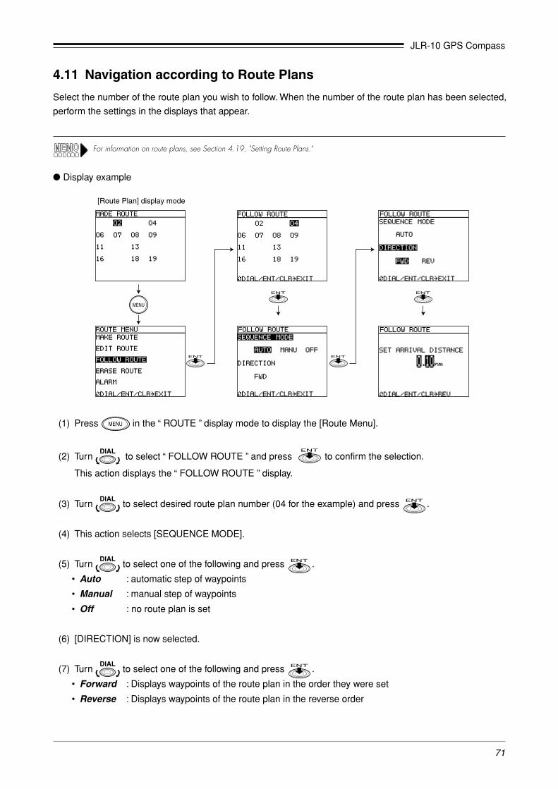
JLR-10 GPS Compass
71
(1) Press in the “ ROUTE ” display mode to display the [Route Menu].
(2) Turn to select “ FOLLOW ROUTE ” and press to confirm the selection.
This action displays the “ FOLLOW ROUTE ” display.
(3) Turn to select desired route plan number (04 for the example) and press .
(4) This action selects [SEQUENCE MODE].
(5) Turn to select one of the following and press .
• Auto : automatic step of waypoints
• Manual : manual step of waypoints
• Off : no route plan is set
(6) [DIRECTION] is now selected.
(7) Turn to select one of the following and press .
• Forward : Displays waypoints of the route plan in the order they were set
• Reverse : Displays waypoints of the route plan in the reverse order
4.11 Navigation according to Route Plans
Select the number of the route plan you wish to follow. When the number of the route plan has been selected,
perform the settings in the displays that appear.
For information on route plans, see Section 4.19, "Setting Route Plans."
� Display example
[Route Plan] display mode

JLR-10 GPS Compass
72
4.12 Entering Current Position as a Waypoint [EVENT]
The current position (buoy or fishing ground) can be turned into a waypoint simply by
pressing . The function is available in the following six main display
modes.
• “ HEADING ” , “ POSITION ” , “ NAVIGATION ” , “ CDI ” , “ PLOT ” and “ MOB ”
display modes.
The procedure to enter the current position as a waypoint is the same in five display modes. Theexample below shows how to do this from the “ POSITION ” display mode.
(1) Press at the position you wish to add as a waypoint.
The “ EVENT ” display appears in place of the “ POSITION ” display.
After “ EVENT ”, the lowest unregistered number is displayed on the second line.
(2) The current position is now registered to the desired number.
• When you wish to register the waypoint to the number that is first displayed, press . Or just wait 5
seconds until the “ EVENT ” display disappears.
• Use the following procedure to register the waypoint to a different number.
Press and turn to select a number. Then press .
• Number of registration: 001 to 499
• When a number where a registration has already been made is selected for registration, the message, “NOW USING”,
“IN ROUTE”, “DEST PT” are indicated and no registration is made.
• Events cannot be registered when the GPS/DGPS receiver is not position fixing.
When events are registered during Processing Unit (or DGPS receiver) position fixing, the following symbols are appended to thewaypoint list:
DGPS position fixing : DGPS position fixing : G
(8) Turn to select values for [SET ARRIVAL DISTANCE] and press .
Setting range: 0.00 to 9.99 nm
The [Position] display mode is now displayed automatically.
The alarm setting made in Section 4.9, “Setting Alarms (Arrival/Anchor/Off-course/DGPS)” are replaced by the arrival
alarm distance made here.
• The route plan numbers entered here are highlighted in the [Route] display mode.• An automatic step cannot be performed by selecting [Auto] in step (5) when [0.00] is set in [Set Arrival Distance]. To make an step,
press , like in manual step, to step the waypoint.• When a value between 0.01 to 9.99 is entered, the alarm sounds when the vessel enters within the set arrival alarm zone from the
waypoint.Auto step : Function that automatically steps from one waypoint to the next when the arrival perpedicular point has been
passed.
Manual step : The next waypoint is stepped by pressing . When is pressed as the vessel enters the set arrival
alarm zone to step to the next waypoint, the alarm is canceled. If is not pressed to perform a step when the
vessel enters the set arrival alarm zone, the alarm will ring until turned off by pressing . (Manual stepping
is valid in “ HEADING ”, “ POSITION ”, “ NAVIGATION ” and “ CDI ” display modes.)

JLR-10 GPS Compass
73
4.13 Man-Over-Board Mode [MOB]
The MOB function (Man-Over-Board) is useful if something or someone falls overboard. Press and the
navigator shows a graphic display of the position allowing you to steer back to the position where the event
occurred.
The function is available in all display modes.
(1) Press .
This action enters the display mode. The ship and the MOB position are
connected by a dotted line. (The alarm can be canceled by pressing .)
(2) The display shows the bearing, distance and elapsed time (minutes and sec-
onds) from the MOB position.
You can now steer back to the MOB position using the display information.
• The plot scale is automatically set to 0.5 nm. An arrival alarm sounds when the
ship is inside 0.1 nm of the MOB position. (The alarm can be canceled by
pressing .)
(3) The MOB function can be canceled and the previous display mode can be redisplayed by pressing
for 3 seconds.
Pressing does not store the MOB position in memory. To store the MOB position in memory, press and
register the MOB position to desired number. (For details, see Section 4.12, “Entering Current Position as a Waypoint
[EVENT].”)
4.14 Position Correction/Geodetic System Correction/Magnetic Compass
Correction
See Section 4.6, "Basic Menu Selection Operations" for information on setting procedures.
Make it a rule to check the geodetic system marine chart and this unit’s
setting before going to sea. If both geodetic systems are different, the dis-
played latitude and longitude indications will differ from those of the chart,
which could lead to a marine accident.
The automatically corrected compass value is an approximate value. For this
reason, manually enter the correct value when you wish to steer the ship on
a correct course according to corrected magnetic compass values.
CAUTION

JLR-10 GPS Compass
74
2. Setting
(1) Position correction
Use this function to adjust the positioning Processing Unit (or DGPS receiver) sensor to marine chart.
N 00.000’ for latitude correction
SW 00.000’ for longitude correction
E
(2) Geodetic system correction
The latitude and longitude of the positioning data can be converted to latitude and longitude data of
another geodetic system. There are a total of 46 geodetic systems. The names of the first nine systems are
displayed by name and the rest are displayed by number. The names of the other geodetic systems are
listed in Appendix 3-B, “Geodetic System Tables.”
GEODETIC See Appendix 3-B, “Geodetic System Tables.”
(3) Magnetic compass correction
MAG CORR AUTO (Automatic magnetic compass correction)
MANU E 00˚ (Manual magnetic compass correction)
W
In a manual setting, it is possible to read the magnetic compass variation from the compass chart of a marine chart. Example: When themagnetic compass shows a reading of 60˚ and the navigator indicates 40˚, the (W) 20˚ difference can be used to correct the navigatorsetting.
The correction value may differ with the sea area. If so, correct as required.
1. Display operations
• Press in the “ POSITION ” display mode.
• To return to the “ POSITION ” display mode, press .
� Display example
[Latitude, Longitude display]

JLR-10 GPS Compass
75
4.15 Setting Navigation Display Modes and Units
1. Display operations
• Press in the “ NAVIGATION ” display mode.
• To return to the “ NAVIGATION ” display mode, press .
2. Setting
(1) Navigation information type
The navigation information can be displayed in one of the following type.
DSP TYPE : BRG/DTG/COG/SOG (default format)
BRG/DTG/XTE/TTGCMG/VTD/COG/SOGBRG/VAH/COG/SOG
CMG and VTD are described in the figure below.CMG : Bearing of the current position as viewed from origin of routeVTD : Velocity toward destinationVAH : Velocity toward heading
NorthNorth
Origin
Planned routeWaypoint
Current position Heading
bac
VTD = V cos a˚CMG = b˚VAH = V cos c˚
VAH
VTD
V (velocity)
Fig. 4-8
(2) Unit
The following navigation information units can be set.
UNIT : NM/KT SM/MH KM/KH
(3) Display language
One of the following seven languages can be set.
LANGUAGE: English (default)/Deutsch/Francais/Español/Norsk/Italiano/ニホンゴ
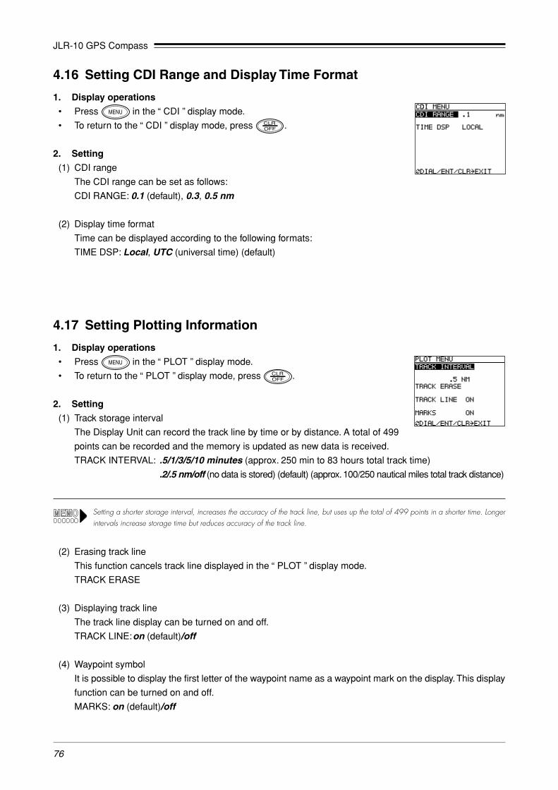
JLR-10 GPS Compass
76
4.16 Setting CDI Range and Display Time Format
1. Display operations
• Press in the “ CDI ” display mode.
• To return to the “ CDI ” display mode, press .
2. Setting
(1) CDI range
The CDI range can be set as follows:
CDI RANGE: 0.1 (default), 0.3, 0.5 nm
(2) Display time format
Time can be displayed according to the following formats:
TIME DSP: Local, UTC (universal time) (default)
4.17 Setting Plotting Information
1. Display operations
• Press in the “ PLOT ” display mode.
• To return to the “ PLOT ” display mode, press .
2. Setting
(1) Track storage interval
The Display Unit can record the track line by time or by distance. A total of 499
points can be recorded and the memory is updated as new data is received.
TRACK INTERVAL: .5/1/3/5/10 minutes (approx. 250 min to 83 hours total track time)
.2/.5 nm/off (no data is stored) (default) (approx. 100/250 nautical miles total track distance)
Setting a shorter storage interval, increases the accuracy of the track line, but uses up the total of 499 points in a shorter time. Longerintervals increase storage time but reduces accuracy of the track line.
(2) Erasing track line
This function cancels track line displayed in the “ PLOT ” display mode.
TRACK ERASE
(3) Displaying track line
The track line display can be turned on and off.
TRACK LINE:on (default)/off
(4) Waypoint symbol
It is possible to display the first letter of the waypoint name as a waypoint mark on the display. This display
function can be turned on and off.
MARKS: on (default)/off

JLR-10 GPS Compass
77
4.18 Entering Waypoints
Waypoints can be entered in one of the following three ways:
• Using to store a waypoint
Press when you pass a fishing point or buoy and enter the desired waypoint number. (See Section
4.12, “Entering Current Position as a Waypoint [EVENT].”)
• Entry of latitude/longitude
Direct entry of latitude/longitude coordinates from marine charts or other navigation information.
• Entry of bearing and distance
Direct entry of bearing and distance from current position of the ship can be calculated.
Up to 499 waypoints can be entered which are numbered from 001 to 499.
To store new numbers and to recall old ones, a number must be entered.
Thus it is a good idea to record the waypoint number and waypoint name in the waypoint list in Appendix 6. (Or
in a copy of this list.)
The following function can be used to look for a registered waypoint.
• Sorting the waypoint list in number order (default) or in alphabetic order.
� WAYPOINT display mode and waypoint menu
• The “ WAYPOINT ” display mode is used for displaying and editing waypoints. (See Section 4.18.1.)
• The following settings can be made in the “ WAYPOINT MENU ” displayed by pressing in the
“ WAYPOINT ” display mode.
- Waypoint setting (by latitude, longitude or bearing/distance) (See Section 4.18.2.)
- Erasing, copying and measuring waypoints (See Section 4.18.3.)
- Sorting waypoint names (See Section 4.18.4)
� Display example
[WAYPOINT] display mode [WAYPOINT Menu] display
For information on entry procedures, see Section 4.6, “Basic Menu Selection Operations.”

JLR-10 GPS Compass
78
4.18.1 Editing Waypoint Lists
Registered waypoints can be displayed in the “ WAYPOINT ” display mode and then edited.
(1) Scroll the list in the “ WAYPOINT ” display mode and select the number to be edited and press .
This action displays the “ WAYPOINT LIST EDIT ” display.
(2) Edit the waypoint and enter it again. This returns you to the “ WAYPOINT ” display mode.
[WAYPOINT] display mode [WAYPOINT LIST EDIT] display
(3) Select waypoint number and press .
If the displayed number is the right one, just press .
4.18.2 Storing Waypoints
1. Storing by LAT/LON (When the [L/L] is selected.)
Use the following procedure to enter waypoint by latitude and longitude.
(1) Press in the “ WAYPOINT ” display mode.
This displays the “ WAYPOINT MENU ”.
(2) Press to select “ ENTER NEW WPT BY L/L ” and press .
The lowest waypoint number that can be entered is displayed. (For the example 001 has been registered.)
� Display example
[First Display]
[WAYPOINTMENU] [WAYPOINTMENU]
[Display showing made entries] [Bearing, distance calculation results]

JLR-10 GPS Compass
79
(3) As in step (1), enter waypoint number and name, and press .
(4) The bearing and distance from current position is entered.
When the entry is complete, the message “CALCULATING” is displayed.
[First Display] [Display showing made entries]
[WAYPOINT MENU] [WAYPOINT MENU]
(4) Enter the name of the waypoint in up to 8 characters.
The alphabet (26 characters), numbers (0 to 9), symbols (6) and spaces can be used for name entries.
Symbol: ( )
Example: ⊿Fish 3
• Turn to select symbol [⊿ ] and press .
• Turn to select space and press .
• Enter up to 8 characters using this procedure.
Since the first character of a waypoint name is displayed as a symbol of the waypoint in “ PLOT ” display mode. It is a good idea toselect a symbol or alphabetic character for the first letter. Also see Section 4.18.4, “Sorting Waypoint Names”.
(5) Set latitude and longitude in stated order.
N XX° ➝ XX. ➝XXX' ➝W XX° ➝ XX. ➝ XXX'S E
When the entry has been made, the message “CALCULATING” is displayed indicating that the bearing
and distance from current position is being calculated. The calculation result is displayed at the bottom of
the screen.
2. Storing by bearing and distance
Use the following procedure to enter bearing and distance to be used in calculating waypoint position.
(1) Press in the “ WAYPOINT ” display mode.
This displays the “ WAYPOINT POINT ”.
(2) Turn to select “ ENTER NEW WPT BY B/R ” and press .
� Display example
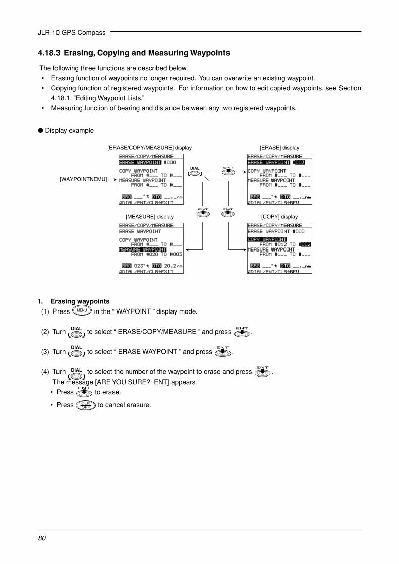
JLR-10 GPS Compass
80
4.18.3 Erasing, Copying and Measuring Waypoints
The following three functions are described below.
• Erasing function of waypoints no longer required. You can overwrite an existing waypoint.
• Copying function of registered waypoints. For information on how to edit copied waypoints, see Section
4.18.1, “Editing Waypoint Lists.”
• Measuring function of bearing and distance between any two registered waypoints.
� Display example
1. Erasing waypoints
(1) Press in the “ WAYPOINT ” display mode.
(2) Turn to select “ ERASE/COPY/MEASURE ” and press .
(3) Turn to select “ ERASE WAYPOINT ” and press .
(4) Turn to select the number of the waypoint to erase and press .
The message [ARE YOU SURE? ENT] appears.
• Press to erase.
• Press to cancel erasure.
[ERASE/COPY/MEASURE] display [ERASE] display
[WAYPOINTNEMU]
[MEASURE] display [COPY] display

JLR-10 GPS Compass
81
2. Copying waypoints
(1) Press in the “ WAYPOINT ” display mode.
(2) Turn to select [ERASE/COPY/MEASURE] and press .
(3) Turn to select [COPY WAYPOINT] and press .
(4) Enter the number of the waypoint to be copied in the [FROM] field.
(5) Enter the number of the destination of the waypoint in the [TO] field. The waypoint has been copied.
If the number of an already registered waypoint is selected as the destination, it will be overwritten by the copied
waypoint.
3. Measuring between waypoints
(1) Press in the “ WAYPOINT ” display mode.
(2) Turn to select [ERASE/COPY/MEASURE] and press .
(3) Turn to select [MEASURE WAYPOINT] and press .
(4) Enter the number of the waypoint to be used as the origin in the [FROM] field.
(5) Enter the number of the waypoint to be used as the end point in the [TO] field.
The bearing and the distance between the waypoints is calculated and the result is displayed at the bottom
of the screen.

JLR-10 GPS Compass
82
This route plan thus consists of harbor AA and the destinations which are the two fishing points (waypoint
numbers 011 and 012) and harbor BB (waypoint 013). In following a set route plan, the navigator switches from
one waypoint to another when it comes within a certain distance of the first waypoint (automatic stepping) or by
manually stepping to the next waypoint.
• For information on entry operations given below, see Section 4.6, “Basic Menu Selection Operations.”• For information on how to follow route plans, see Section 4.11, “Navigation according to Route Plans.”
Harbor AA(waypoint number 010)
Fishing point (waypoint number 011)
Fishing point (waypoint number 012)
Harbor BB(waypoint number 013)
4.18.4 Sorting Waypoint Names
The waypoint list can be sorted either in number order or in the alphabetic order of the waypoint names. In
alphabetic order, characters are sorted in the following order: symbols, alphabetic characters, numbers and
spaces.
(1) Press in the “ WAYPOINT ” display mode.
This displays the “ WAYPOINT MENU ”.
(2) Turn to select [WPT SORT] and press .
(3) Turn to select 123 or ABC and press .
123 (default) : sorts the waypoints in number order
ABC : sorts the waypoints in alphabetic order.
� Display example
4.19 Setting Route Plans
A route consisting of several connected waypoints is called a route plan. For example, say that you go from a
harbor (waypoint number 010), to a fishing point (waypoint number 011), to another fishing point (waypoint
number 012) and then return to a different harbor (waypoint number 013).
[Waypoint display for ABC sort]
[WAYPOINT MENU]
Fig. 4-9

JLR-10 GPS Compass
83
4.19.1 Making a Route Plan
The following displays are used for making route plans.
� Display examples
(1) Press in the “ ROUTE ” display mode.
This displays the “ ROUTE MENU ”.
(2) Turn to select “ MAKE ROUTE ” and press .
This displays the “ MAKE ROUTE ” display and the numbers that can be used for a new route plan. (The
display above shows that 02, 04, 07-09, 11, 13, 16, 18 and 19 are already taken.)
(3) Turn to select desired route plan number (01 in the example) and press .
The display title changes to “ MAKE ROUTE #01 ”.
(4) Enter the origin of waypoint number 001 in the [FROM] field for the first route (LEG 001) of route plan #01.
(The name of route number 001 is shown in the display.)
(5) Enter the number of the next waypoint in the [TO] field.
The entries made for route (LEG 001) and the calculated bearing and distance between the two waypoints
are displayed.
• Press to end a route plan.
• To enter the next route (LEG 002 to), repeat steps (4) and (5).
You can use steps (4) and (5) to enter up to 20 routes consisting of up to 199 waypoints.
[Route Plan] display mode
Rep
eat

JLR-10 GPS Compass
84
[Made Route] [Erase waypoint 003] [Insert waypoint 005]
Leg 001Leg 002
Leg 001 Leg 001Leg 002
Leg 003
Leg 003
Leg 004Leg 002
4.19.2 Editing Route Plan
Waypoints can be inserted to or deleted from registered route plans as you wish.
Use and in the [Edit Route] display mode as shown below.
• : Key for inserting waypoint numbers
• : Key for deleting waypoint numbers
� Display examples
[ROUTE] display mode
[Delete]
[Insert]
(1) Press in the “ ROUTE ” display mode.
(2) Turn to select [EDIT ROUTE] and press .
(3) Turn to select desired route plan number (02 for the example) and press .
The display mode title changes to [EDIT ROUTE #02].
Fig. 4-10

JLR-10 GPS Compass
85
4.19.3 Erasing Route Plans
Registered Route plans can be erased using the procedure described below.
� Display example
(1) Press in the “ ROUTE ” display mode.
(2) Turn to select [ERASE ROUTE] and press .
(3) Turn to select the desired route plan number (02 for the example) and press .
This displays the message [ARE YOU SURE? ENT].
(4) Press once more to erase the selected route plan after which the “ ROUTE MENU ” appears.
• To cancel deletion, press instead.
[Route Menu]
[ROUTE] display mode
(4) This example will show how to delete waypoint 003 from LEG 002 and to insert a new waypoint 005.
• Deleting waypoint #003
As shown above, turn to select LEG002 and press to confirm LEG002.
Press to delete #003 of LEG002. This deletes waypoint #003 and the total number of legs are
decremented.
• Insert waypoint #005
As shown above, turn to select LEG002 and press to confirm LEG002.
Press , enter #005 for #003 and press .
Waypoint #005 is inserted and the number of leg are incremented.
You cannot edit a route plan that is being executed.
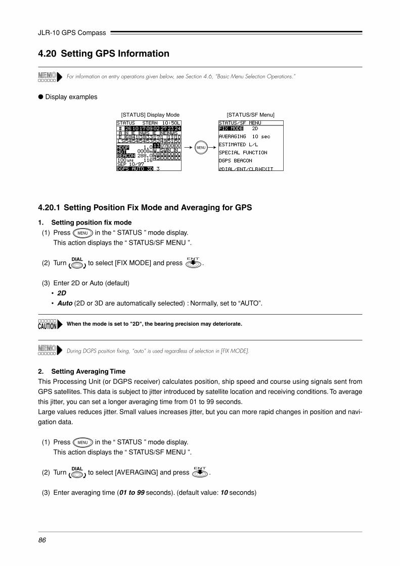
JLR-10 GPS Compass
86
4.20 Setting GPS Information
For information on entry operations given below, see Section 4.6, “Basic Menu Selection Operations.”
� Display examples
4.20.1 Setting Position Fix Mode and Averaging for GPS
1. Setting position fix mode
(1) Press in the “ STATUS ” mode display.
This action displays the “ STATUS/SF MENU ”.
(2) Turn to select [FIX MODE] and press .
(3) Enter 2D or Auto (default)
• 2D• Auto (2D or 3D are automatically selected) : Normally, set to “AUTO”.
When the mode is set to "2D", the bearing precision may deteriorate.
During DGPS position fixing, “auto” is used regardless of selection in [FIX MODE].
2. Setting Averaging Time
This Processing Unit (or DGPS receiver) calculates position, ship speed and course using signals sent from
GPS satellites. This data is subject to jitter introduced by satellite location and receiving conditions. To average
this jitter, you can set a longer averaging time from 01 to 99 seconds.
Large values reduces jitter. Small values increases jitter, but you can more rapid changes in position and navi-
gation data.
(1) Press in the “ STATUS ” mode display.
This action displays the “ STATUS/SF MENU ”.
(2) Turn to select [AVERAGING] and press .
(3) Enter averaging time (01 to 99 seconds). (default value: 10 seconds)
[STATUS] Display Mode [STATUS/SF Menu]

JLR-10 GPS Compass
87
4.20.2 Initializing GPS
During fixing after the power is turned on, the "HEADING" display mode is displayed. Therefore, initial settings
are enabled by selecting the "STATUS/SF MENU".
� Display example
(1) Press in the “ STATUS ” display mode.
This action displays the “ STATUS/SF MENU ”.
(2) Turn to select [ESTIMATED L/L] and press .
The [ENTER YOUR LATITUDE] is highlighted.
(3) Enter the estimated position of the ship. (within a deviation range of 1˚).
[ANT HT] is now highlighted.
(4) Enter the height of the ship’s antenna.
[DATE] is now highlighted.
(5) Enter local time (date). (month/day/year)
[TIME] is now highlighted.
(6) Enter local time (time). (hour /minute/second)
There is no need to enter the second value, only press .
[STATUS/SF Menu] [ESTIMATED L/L] [ESTIMATED L/L]

JLR-10 GPS Compass
88
(1) Press in the “ STATUS ” display mode.
This action displays the “ STATUS/SF MENU ”.
(2) Turn to select [DGPS Beacon] and press .
When a DGPS beacon receiver or DGPS receiver (DGPS212) is not connected, the message [No CONNECT] shows.
(3) Setting Receive mode
Turn to select mode and press .
When [Auto] is selected, the display returns to [STATUS/SF Menu].
(4) Enter the frequency and Baud rate.
When [Manual] is set, enter the values in [FREQUENCY] and [BAUD RATE].
4.20.3 Setting DGPS Beacon
The frequency and Baud rate of the beacon station received on the DGPS receiver (option) or DGPS beacon
receiver can be set.
� Display example
[STATUS/SF Menu] display mode [STATUS/SF MENU DGPS] display mode

JLR-10 GPS Compass
89
4.21 Setting Output Level and Transmitting/Receiving Memory Data
When a Personal Computer (PC) is connected to Display Unit, the output level must be set to TTL when data is input
from the PC since an RS-422 setting could damage the PC and Display Unit.
Data transmission/reception with external equipment can be performed using the DATA IN/DATA OUT lines of
the Display Unit Data Cable (option).
• Output level
The output level can be set to TTL or RS-422 when data is exchanged with external equipment (NMEA0183
data output, memory data I/O).
The output level must be set before data is exchanged with external equipment.
The following two types of data are supported in communications with external equipment.
• Output data
GPS data conforming to the NMEA183 format and navigation data are output (For details, see Appendix 4,
“Data Output”)
• Memory data I/O
The JLR-10 can transfer the waypoint and route memory contents of the internal memory to external
equipment (PC) and re-load back from to the JLR-10. (See Appendix 5, “Waypoint/Route Plan Data In/
Output.”)
� Display example
[STATUS S/F MENU] display mode [Special Function] display mode [Special Function Data Output] display mode
[Special Function Memory In/Out] display Mode

JLR-10 GPS Compass
90
1. Output level setting
(1) Press in the “ STATUS ” display mode.
This action displays the “ STATUS/SF MENU ”.
(2) Turn to select [SPECIAL FUNCTION] and press .
The “ SF MENU ” display mode appears.
(3) Turn to select [DATA OUTPUT] and press .
The “ SF MENU DATA OUTPUT ” display mode appears.
(4) Turn to select [OUTPUT LEVEL] and press .
(5) Set the output level (RS-422/TTL (default))
2. Transmitting/Receiving Memory Data
(1) Press in the “ STATUS ” display mode.
This action displays the “ STATUS/SF MENU ”.
(2) Turn to select [SPECIAL FUNCTION] and press .
The “ SPECIAL FUNCTION ” display mode appears.
(3) Turn to select [MEMORY IN/OUT] and press .
This displays the “ SPECIAL FUNCTION MEMORY IN/OUT ” display mode.
(4) Memory Data Output
Waypoint and route plan data can be uploaded separately to external equipment such as a PC.
This data can be saved and edited on external equipment.
During the upload the message [UPLOADING] is displayed. The time required for the transfer depends on
the amount of data transferred.
• Waypoint data output
Select [OUTPUT WPT DATA] and press .
• Route plan data output
Select [OUTPUT ROUTE DATA] and press .
(5) Memory data input
Waypoint and route plan data can be downloaded separately from external equipment such as a PC.
During the download the message [DOWNLOADING] is displayed. When the message “DOWNLOAD-
ING” is displayed, inputs are received from external equipment. The time required for the transfer de-
pends on the amount of data transferred.
• Waypoint data input
Select [INPUT WPT DATA] and press .
• Route plan data input
Select [INPUT ROUTE DATA] and press .
The transfer rate is one memory per second.

JLR-10 GPS Compass
91
4.22 Performing Master Reset
• A master reset clears registered data. Use this function with care.
• After resetting this equipment, perform GPS Initialization. (See Section 4.20.2, “Initializing GPS”.)
There are soft and hard reset functions. A soft reset clears all data except waypoint and route plan data. Thus
items set or selected through operation are all returned to their default values. A hard reset clears all data
including waypoints and route plans.
� Display example
[STATUS/SF Menu] display mode [SF Menu] display mode
(1) Press in the “ STATUS ” display mode.
This action displays the “ STATUS/SF MENU ”.
(2) Turn to select [SPECIAL FUNCTION] and press .
The “ SPECIAL FUNCTION ” display mode appears.
(3) Turn to select [MASTER RESET] and press .
(4) Select soft or hard reset and press .
A soft or hard reset is performed.

JLR-10 GPS Compass
92
Daily maintenance and inspections will keep your equipment in good working conditions and prolong itsservice life. We would recommend you to make the following inspections before commencing the equipmentoperation.
� Is the equipment properly secured? Are any of the mounting screws loosened? ➔ Secure it as required.� Are the connecting cables securely connected? ➔ Connect them securely.� Is the fuse blown? ➔ Replace the fuse with a specified one.� Is the equipment damaged? ➔ Consult our local sales office or your distributor if an equipment
malfunction is noted.� Is any connecting cable damaged? ➔ Use of damaged cables can cause a fire, electric shock or
equipment failure. Consult our local sales office or your distribu-tor for repair or replacement.
5. Maintenance and Inspection
No attempt shall be made by the user to inspect or repair the equipment.Inspections or repairs carried out by unauthorized personnel can cause afire or electric shock.Consult our local sales office or a dealer nearby your location for any inspec-tion or repair that requires the equipment disassembly.
WARNING
Use only the specified fuse.Failure to observe the instruction can cause a fire or equipment failure.
Model : MF51NN-2A 2 amp
Do not use a non specified battery.Failure to observe this instruction can cause equipment failure ormalfunction.The Display Unit and the Processing Unit is equipped with a lithium battery toback up the RAM in the event of a power failure. The lithium battery has anaverage life of approx. five years, however, scheduled replacement is recom-mended before it is completely depleted to ensure proper equipment operation.Consult our local sales office or your distributor to have the battery replaced.
Model : CR2032-THD JRC code : 5ZBBJ00006 (NWZ-4551G)Model : CR2354-1VC JRC code : 5ZBAB00108 (NNN-10)Model : CR2477-1VC JRC code : 5ZBBD00012 (NNN-10)
CAUTION

JLR-10 GPS Compass
93
6. Measures for the Operating Environment Do not install the equipment in any one of the following environments. Failure to observe this instruction can
cause equipment failure or reduced service life.
� Locations that are subject to direct intense sunlight for extended periodsFailure to observe the instruction can cause erratic contrast of the screen display. In addition, the service
life of the LCD will be reduced.
� Locations nearby the equipment that are generating a magnetic fieldFailure to observe this instruction can cause equipment malfunction or display noise.
� Locations with poor ventilationFailure to observe this instruction can cause equipment over-heating, which in turn can cause failure of the
power supply unit.

JLR-10 GPS Compass
94
7. After-sale Services� When asking for service
When you think the equipment is not operating properly, consult our local sales office or your nearby
authorized JRC dealer.
� Repairs during the warranty period
Should a malfunction or failure occur when the equipment is operated according to the descriptions
and instructions contained herein, it will be repaired free of charge during the warranty period. How-
ever, any repair for failures resulting from misuse, abuse, fire, or other unforeseeable incident will be
charged.
� Repairs after the warranty period
Repairs to restore the proper equipment operation can be made at a specified rate with the user’s
consent.
� Information that needs to be provided when you ask for the service
◯ Name, model and serial number of the equipment
◯ Description of the malfunction (as detailed as possible)
◯ Name, address, and phone number of your company or organization
� Recommended checks and inspectionsThe equipment performance is subject to decay due to age and change of component values over time.
Thus, it is recommended to consult with our local sales office or your dealer for periodic inspection and
maintenance in case of loss in performance, in addition to your own routine inspection and maintenance.
This inspection is not covered by warranty.
Note that, however, the user needs to pay for such a periodic inspection and maintenance.
Direct your inquiries to any one of our local sales offices or your distributors listed at the end of this
manual.
JLR-10 GPS Compass
95
8. Disposal
Insulate the used lithium battery, such as placing a piece of insulation tape
both on the anode and cathode terminals of the battery before disposing of
it. Failure to observe the instruction can cause a fire, explosion, or other
hazards due to shorted battery.
8.1 Disposal of the Equipment
� Observe all the applicable acts and regulations specified by the local authority.
8.2 Disposal of the Used Battery
A lithium battery is mounted in the Processing Unit and Display Unit to back up data.
� Dispose of the used lithium battery each time as a piece of non-combustible garbage without storing it.
� Insulate the used lithium battery, such as placing a piece of insulation tape both on its anode and cathode
terminals before disposing of it. Note that the battery needs to be disposed of according to the rules
specified by the applicable local authority, if any.
Consult our local sales office, your distributor, or local authority for further details on the disposal method.
WARNING

JLR-10 GPS Compass
96
9. Specifications1. Function specifications
(1) True bearing output : 0.0 to 359.9˚
(2) Data output : NMEA0183
Heading : HDT
Navigation data : HDT, GGA, GLL, RMC, VTG, GNS, ROT, DTM etc.
NSK format (for JRC radar)
(3) Data input : RTCM SC-104 (DGPS correction data)
(4) Input voltage : DC +12V/24V (DC 10.8V to 31.2V)
2. Performance specifications
(1) Direction accuracy : 1˚rms
(2) Resolution : 0.1˚
(3) Tracking rate of turn : More than 25˚/sec.
(4) Tracking acceleration : 1G
(5) Maximum roll and pitch angle
: ±30˚
(6) Data output : Heading NMEA (HDT) 4800 bps output rate 50 msec., 100 msec.
NSK format 9600 bps output rate 20 msec.
Display data 4800 bps output rate 1 sec.
Rate of turn NMEA (ROT) 4800 bps output rate 50 msec.
Navigation data 4800 bps output rate 1 sec.
3. Environment
(1) Operating temperature : Antenna Unit -25˚C to +55˚C
Processing Unit, Display Unit -15˚C to +55˚C
(2) Operating humidity : 93%, 40˚C
(3) Storage temperature : -30˚C to +70˚C
(4) Vibration : IEC60945 comormity
(5) EMC : IEC60945 comormity
(6) Waterproof : Antenna Unit CFR46 equivalent
Processing Unit JIS Drop proof type II (IPX2 equivalent)
Display Unit JIS Jet proof (IPX5 equivalent)

JLR-10 GPS Compass
97
Appendices

JLR-10 GPS Compass
98
Appendix 1 Optional Unit
� Summary of GPS Repecon
� Key specifications
(1) Repeater compass angular velocity (max.)
: 14˚/sec.
(2) Input voltage : AC100, 60Hz, 40VA
(3) Outside dementions : W 300mm ✕ H 300mm ✕ D 120mm
(4) Mass : 10O
(5) Operation environment (inboard)
: Temparature -15˚C to +55˚C
Humidity 40˚C, 93% (No dew condensation)
Fig. A-1
Navigation equipmentof every company
Steerage stand
U V R1
Rx+Rx- E
R2 S1 S2 S3E
R1 R2 S1 S2 S3E
E
R1 R2 S1 S2 S3
Course settingUnit
Power
RepeaterAC100V60Hz
GPS Repecon(made by AIDEN)
GPS compass
NSK›Synchro converter
ES-11AGPS compass
made byTOKIMEC
FUSE FUSE FUSE FUSE FUSE
POWER REPEARERCOMPASS
GYROCOMPASS
GPS
REPEATERCOMPASS
GYROCOMPASS
GPS
NAVIGATIONEQUIPMENT
DEC.
SYNCHRO ADJUSTNID2001INC.
LOCK
GPS-REPECONPOWER (3A) REPEATER
COMPASSNAVIGATIONEQUIPMENT
GYROCOMPASS
SYNCHROSYGNAL
� Outline drawing� Connection
Fig. A-2

JLR-10 GPS Compass
99
� Summary of DGPS Beacon Receiver
Fig. A-3 Outline drawing of NRB-2J DGPS beacon receiver
(ø198)
ø52±2
ø110±2
129±
4
NOTE : ( ) indicate a reference value.
(ø150)
(42)
Unit : mm
Mass : approx. 1.3O (including the cable, excluding the whip antenna)
Pin arrangement of connector
5 1
24
3
Pin No. Color of wire Remarks
1 Red DC 12V
2 Black GND
3 White Data common
4 Green Data output
5 Yellow Setting data input
Fig. A-4

JLR-10 GPS Compass
100
500
135
1inch 14 UNS-28ø40
ø126
Pin arrangement of connector
5 1
24
3
Pin No. Color of wire Remarks
1 Red DC 12V
2 Black GND
3 White Data common
4 Green Data output
5 Yellow Setting data input
Fig. A-6
� Summary of DGPS Receiver
Fig. A-5 Outline drawing of JLR-4331 DGPS receiver
Unit : mm
Mass : approx. less than 1.1O

JLR-10 GPS Compass
101
15000±200
50±5
25±5
2±1
55.5
ø6.7
Fig. A-7 Outline drawing of CFQ-6559 OPTION cable
� Summary of OPTION Cable
Fig. A-8
Unit : mm
4
6 8 2
5 3
7 1
Pin No. Color of wire Remarks
1 Brown Open
2 Red Open
3 Orang Heading data output RS-422 +
4 Yellow Heading data output RS-422 –
5 Green Data common (Ground)
6 Blue Heading data output TTL
7 Purple Open
8 Gray Open
Pin arrangement of connector

JLR-10 GPS Compass
102
15000±200
41.550±5
25±5
2±1
ø6.7
2
345
101112
9 8 7 6
1
14 13
� Summary of NMEA Cable
Fig. A-10
Fig. A-9 Outline drawing of CFQ-6560 NMEA cable
Unit : mm
Pin arrangement of connector
Pin No. Color of wire Remarks
1 Brown NMEA0183 Navigation data RS-422 +
2 Red NMEA0183 Navigation data RS-422 –
3 Orang NMEA0183 HDT RS-422 +
4 Yellow NMEA0183 HDT RS-422 –
5 Green NMEA0183 ROT RS-422 +
6 Blue NMEA0183 ROT RS-422 –
7 Purple Alarm (Contact signal) +
8 Gray Alarm (Contact signal) –
9 White Log pulse (Contact signal) +
10 Black Log pulse (Contact signal) –
11 Pink NMEA0183 Display data RS-422 +
12 Brown/White NMEA0183 Display data RS-422 –
13 Red/White Open
14 Black/White Open

JLR-10 GPS Compass
103
Appendix 2 Cable Connection of the Attached Connector (N-P-5-2)
• Remove sheath of the cable in the length shown in the
Fig. A-11.
Don’t put a wound on shielding wire at this time.
1. Pealing sheath of the cable
12.7
Fig. A-11
2. Fixing parts
• Fix a tightening parts, washer, gasket and clamp accord-
ing to Fig. A-12.Tightening parts
WasherGasket Clamp
Fig. A-12
3. Teratment of shielding wire
Insulator and foil
Fig. A-13
4. Fixing a bushing and cutting a insulator
6.0
Core wireCentral contact
Bushing
Fig. A-14
• Turn up shielding wire on the clamp and cut it to an even
length.
• Fix a bushing, cut insulator and foil of the cable on the
edge of the bushing, and remove them.
Don’t put a wound on core wire at this time.
Match the length of core wire with the length shown in
Fig. A-14

JLR-10 GPS Compass
104
5. Solering a center contact
Soldering
Fig. A-15
6. Fixing a insulator
Insulator of the cable
Fig. A-16
7. Fixing into a connector
Tightening with spanner
CAUTION)1. When tightening with spanner, don't
scar the connector or tightning parts.2. Don't keep loosen the tightning parts.
Fig. A-17
• Solder core wire for preparation, insert a center
contact, and solder it pouring solder from the hole
of center contact.
• Solder not to make a gap between the center con-
tact and the insulator.
Check solder leaking and fillet, and confirm
whether solder is firmly attached by pulling the
center contact.
• Using solder : RH-60 1.0
Solder iron
Temperature sensor
• Insert a insulator of the connector into a block sol-
dered the center contact.
• Fix the cable block into the connector with warn-
ing against gaps between each parts.
• Thrust by hand at first, and bound tight using a
torque wrench.

JLR-10 GPS Compass
105
Appndix 3-A Message List
� Error message
Message Description
RAM NG Display RAM failure. Contact JRC sales department or local branch.
ROM NG Display ROM failure. Contact JRC sales department or local branch.
RCV NG Processing Unit is not connected or is malfunctioning.
Connect Processing Unit properly. If the message still persists, contact JRC sales
department or local branch.
� Navigation alarms
Message Description
ARV Arrival alarm. The ship has come inside set arrival range.
Press to silence alarm. The alarm is off when the distance is set to 0.00 m.
ANC Anchor alarm. The ship has drifted outside the set distance range.
Press to silence alarm. The alarm is off when the distance is set to 0.00 m.
XTE Off-course alarm. The ship has drifted more than the set distance off course.
Press to silence alarm. The alarm is off when the distance is set to 0.00 m.
HDOP Indicates poor HDOP value. The HDOP indicator flashes when HDOP exceeds 4.
Since HDOP is poor, Processing Unit (or DGPS receiver) position accuracy is poor.
The alarm goes off when HDOP improves.
NO FIX Processing Unit (or DGPS receiver) is not position fixing. Press to silence
alarm.
Install antenna in location with better reception.
GPS DGPS alarm. When a DGPS alarm is set to on and the Processing Unit (or DGPS
receiver) goes from DGPS to GPS position fixing, the buzzer sounds once.
MOB MOB function (displayed in the title area). The MOB function is canceled when
is pressed for 3 seconds or longer.
NO HWADING Processing Unit is not outputing effective heading.
Press to silence alarm.

JLR-10 GPS Compass
106
� Operation message
Message Description
Too many events (waypoints) registered. This message is displayed when an at-
tempt is made to register a new event when all event points are being used.
Delete old data before making new registration.
Too many waypoints registered. Delete old data before making new registration.
This message is displayed when an attempt is made to set a waypoint by entering
positions, bearings or distance after the waypoint list is full.
No waypoint has been registered.
Register a waypoint.
Too many routes registered. Delete old route before making new registration.
No route has been registered.
Register a route.
A registered waypoint number has been specified in the registration of an event.
Register the event in a free waypoint number.
Confirmation message asking if a waypoint or route plan should be deleted.
Press to delete. To cancel deletion, press .
The program is calculating distance or position of waypoint or route plan.
Please wait.
The unit is downloading data from external equipment. Please wait.
The unit is uploading data to external equipment. Please wait.
No waypoint was set in a route plan or in direct route.
EVENT FULL
WPT FULL
NO WAYPOINT
ROUTE FULL
NO ROUTE
NOW USING,
IN ROUTE,
DEST PT
ARE YOU SURE?
ENT
CALCULATING
DOWNLOADING
UPLOADING
WPT NO DEST

JLR-10 GPS Compass
107
� Bearing alarms
Message Description
0 (No display) Normal
1 Common reception satellites for two antennas (BOW, STERN) are four
This message shows only STATUS display.
2 Heading calculation disabled (the case of receiving from five or more satellites)
3 Heading calculation un-completing
4 Common reception satellites for two antennas (BOW, STERN) are three or less
6 Heading calculation disabled (the case of receiving from four satellites)
7 Aux. sensor is failure (the bearing of heading)
8 Aux. sensor is failure (the bearing of roll)
9 Aux. sensor is failure (the bearing of pich)
� Antenna alarms
Message Description
No display Normal
O Open (No antenna is connected)
S Short (Antenna fault)

JLR-10 GPS Compass
108
Names displayed on the screen Geodetic systems
WGS-84 WGS-84
WGS-72 WGS-72
JAPAN Japanese geodetic system
NAD27 USA North American 1927 (USA)
NAD27 CAN North American 1927 (Canada and Alaska)
EUROPE 50 Europe 1950 (Europe)
AUSTRA 66 Australian geodetic 1966 (Australia)
OSGB-36 Ordnance Survey of Great Britain (UK)
NAD-83 NAD-83
Table 1
Appndix 3-B Geodetic System Tables
� Geodetic systems that are displayed by the respective names (Nos. 1 to 9)

JLR-10 GPS Compass
109
Names displayed on the screen Geodetic systems
11 Adindan (Ethiopia and Sudan)
12 ARC 1950 (Botswana)
13 Australian Geodetic 1984 (Australia)
14 Bermuda 1957 (Bermuda islands)
15 Bogota Observatory (Columbia)
16 Compo Inchauspe (Argentina)
17 Chatham 1971 (Chatham islands)
18 Chua Astro (Paraguay)
19 Corrego Alegre (Brazil)
20 Djakarta (Batavia) (Sumatra)
21 European 1979 (Europe)
22 Geodetic Datum 1949 (New Zealand)
23 Guam 1963 (Guam)
24 Hayford 1910 (Finland)
25 Hjorsey 1955 (Iceland)
26 Indian (India and Nepal)
27 Ireland 1965 (Ireland)
28 Kertau 1948 (West Malaysia and Singapore)
29 L.C.5 Astro (Cayman Black Islands)
30 Liberia 1964 (Liberia)
31 Luzon (Philippines)
32 Merchich (Morocco)
33 Minna (Cameroon)
34 Nahrwan (Oman)
35 Naparima, BWI (Trinidad and Tobago)
36 Old Egyptian (Egypt)
37 Old Hawaiian (Hawaii Islands)
38 Pico de las Nieves (Canary islands)
39 Provisional South American 1956 (South America)
40 Provisional South Chilean 1963 (Southern Chili)
41 Puerto Rico (Puerto Rico and Virgin Islands)
42 Qornoq (Southern Greenland)
43 RT90 (Sweden)
44 Santa Braz (San Miguel and Santa Maria Islands)
45 South American 1969 (South America)
46 Southwest Base (Faial, Graciosa, Pico, Sao Jorge,
and Terceira Islands)
47 Timbalai 1948 (Brunei and East Malaysia)
Table 2
� Geodetic systems that are displayed in numbers

JLR-10 GPS Compass
110
Appendix 4 Data Output
1. Sentences are not always output in the ordar indicated below.
For receiving sentences, enable it take in, no matter sentences may be located in a line with what turn.
2. Each sentence is variable length.
For receiving sentences, enable it to take in the data of variable length.
� Data output from Processing Unit
(1) Data output of each output connector
• “DISP” connector : Display data
• “RADAR” connector : NSK data or heading data F (alternative)
Display data
• “OPTION” connector : NSK data or heading data F (alternative)
• “NMEA” connector : Navigation data
Display data
Heading data S
Rate of turn data
(2) NMEA0183 output sentences
GGA : GPS fix data
RMC : Recommended minimum specific GPS data
GLL : Geographic position - Latitude/Longitude
VTG : Course over ground and ground speed
HDT : True bearing of ship heading
ROT : Rate of turn and direction of turn
GSA : GPS DOP and active satellites
GSV : GPS satellites in view
DTM : Datum reference
GNS : GNSS fix data
ZDA : Time and date
(3) Output timing
q Dispaly data
GGA / RMC / GLL / VTG / HDT : 1 sec. interval
GSV / GSA / DTM : 3 sec. interval
w Navigation data
GNS / RMC / VTG / HDT / ROT : 1 sec. interval
DTM/ ZDA : 2 sec. interval
(✽ When the DGPS receiver is connected, GNS sentences are not output.)
e Heading data
Heading data F HDT : 50 msec. interval
Heading data S HDT : 100 msec. interval
r Rate of turn data
ROT : 50 msec. interval
Attention

JLR-10 GPS Compass
111
(4) Serial format
Baud rate : 4800 bps
Data bits : 8 bits
Parity : None
Start bit : 1 bit
Stop bit : 1 bit
(5) Data format
GGA (GPS fix data)
$GPGGA,hhmmss,ddmm.mmmm,a,ddmm.mmmm,a,x,xx,xx,uxxxx,M,uxxx,M,www,wwww*hh<CR><LF>1 2 3 4 5 6 7 8 9 10 11 12 13 14 15
1 : UTC of position fix (Hour, Minute, Second)
2, 3 : Latitude (Degree, Minute), N/S
4, 5 : Longitude (Degree, Minute), E/W
6 : GPS quality indicator
0 = GPS No Fix
1 = GPS Fix
2 = Differential GPS Fix
7 : Number of satellites in use for position fix
8 : Hrizontal dilution of precision (HDOP)
9, 10 : Antenna altitude above/below mean-sea-level (m) u : sign (+, –)
11, 12 : Geoidal height (m) u : sign (+, –)
13 : Age of Differential GPS data ("00" field when DGPS is not used)
14 : Differential reference station ID ("0000" field when DGPS is not used)
15 : Checksum
RMC (Recommended minimum specific GPS data)
$GPRMC,hhmmss,f,ddmm.mmmm,a,dddmm.mmmm,a,xxx.x,xxx,xxxxxx,,*hh<CR><LF>1 2 3 4 5 6 7 8 9 10
1 : UTC of position fix (Hour, Minute, Second)
2 : Data Status
A = valid
V = invalid
3, 4 : Latitude (Degree, Minute), N/S
5, 6 : Longitude (Degree, Minute), E/W
7 : Speed over ground (knot)
8 : Course over ground, degrees True
9 : Data : Day, Month, Year (UTC)
10 : Checksum

JLR-10 GPS Compass
112
GLL (Geographic position - Latitude/Longitude)
$GPGLL, dd.mm.mmmm, a, dddmm.mmmm, a, hhmmss.ss, A*hh<CR><LF>1 2 3 4 5 6 7
1, 2 : Latitude (Degree, Minute), N/S
3, 4 : Longitude (Degree, Minute), E/W
5 : UTC of position fix (Hour, Minute, Second)
6 : Data status
A = valid
V = invalid
7 : Checksum
VTG (Course over ground and ground speed)
$GPVTG,xxx.x,T,,,xxx.x,N,xxx.x,K*hh<CR><LF>1 2 3 4 5 6 7
1, 2 : Course, degree, true
3, 4 : Speed (knots)
5, 6 : Speed (km/hr)
7 : Checksum
HDT (True bearing of ship's heading)
$GPHDT,xxx.x,T*hh<CR><LF>1 2
1 : True bearing (0 to 359.9˚)
2 : Check sum
ROT (Rate of turn and direction of turn)
$GPROT,uxxxx.x,A*hh<CR><LF>1 2 3
1 : Rate of turn (0 to 9999.9) (Degree, Minute) u : sign (+, –)
2 : Data Status
A = valid
V = invalid
3 : Checksum

JLR-10 GPS Compass
113
GSA (GPS DOP and active satellites)
$GPGSA, a, x,xx,xx,xx,xx,xx,xx,xx,xx,xx,xx,xx,xx,xx.x,xx.x,xx.x*hh<CR><LF>1 2 3 4 5 6 7 8 9 10 11 12 13 14 15 16 17 18
1 : Mode
M = Manual (fixed in 2D or 3D)
A = Automatic
2 : Dimension mode
1 = Fix not available
2 = 2D
3 = 3D
3 to14 : PRN numbers of satellites used in solution ("00" field when satellites are less than 12)
15 : PDOP (fixed length with 4 digits)
16 : HDOP (fixed length with 4 digits)
17 : VDOP (fixed length with 4 digits)
18 : Checksum
GSV (GPS satellites in view)
$GPGSV, x, x, xx,xx,xx,xxx,xx,xx,xx,xxx,xx,xx,xx,xxx,xx,xx,xx,xxx,xx*hh<CR><LF>1 2 3 4 5 6 7 8 9 10 11 12 13 14 15 16 17 18 19 20
1 : Total number of GSV messages (1 to 3)
2 : GSV message number (1 to 3)
3 : Total number of satellites in view (fixed length with 2 digits)
4 : 1st satellite PRN number (01 to 32) (fixed length with 2 digits)
5 : 1st satellite's elevation (00 to 90˚) (fixed length with 2 digits)
6 : 1st satellite's azimuth (000 to 359˚ true) (fixed length with 3 digits)
7 : 1st satellite's SNR (C/No) (00 to 99 dB) (fixed length with 2 digits)
8 to 11 : 2nd satellite's data (same procedure as 4 to 7)
12 to 15: 3nd satellite's data (same procedure as 4 to 7)
16 to 19: 4nd satellite's data (same procedure as 4 to 7)
20 : Checksum
DTM (Datum reference)
$GPDTM, ccc, a,,,,,,ccc*hh<CR><LF>1 2 3 4
1 : Local datum W84 - WGS84
W42 - WGS72
IHO - datum code
✽✽✽ - another datum number
2 : Local datum subdivision code
3 : Reference datum
Null or W84-WGS84
4 : Checksum

JLR-10 GPS Compass
114
GNS (GNSS fix data)
$GPGNS, hhmmss, ddmm.mmmm, a, dddmm.mmmm, a, c, xx, xx, uxxxx, uxxxx, xx, xxxx*hh<CR><LF>1 2 3 4 5 6 7 8 9 10 11 12 13
1 : UTC of position fix (Hour, Minute, Second)
2, 3 : Latitude (Degree, Minute), N/S
4, 5 : Longitude (Degree, Minute), E/W
6 : GPS quality indicator
0 = GPS No Fix
1 = GPS Fix
2 = Differential GPS Fix
7 : Number of satellites in use for position fix
8 : Horizontal dilution of precision (HDOP) (0 to 20)
9 : Antenna altitude above/below mean-sea-level (m) u : sigh (+, –)
10 : Geoidal height (m)
11 : Age of Differential GPS data (null field when DGPS is not used)
12 : Differential reference station ID (0000 to 1023)
ZDA (Time and data)
$GPZDA, hhmmss, xx, xx, xxxx,, *hh<CR><LF>1 2 3 4 5
1 : UTC time (Hour, Minute, Second)
2 : DAY (UTC) (01 to 31)
3 : Month (UTC) (01 to 12)
4 : Year (UTC)
5 : Checksum

JLR-10 GPS Compass
115
� Data output from Display Unit
(1) NMEA0183 output sentences
RMC : Recommended minimum specific GPS data.
RMB : Recommended minimum navigation information.
APB : Autopilot sentence “B”.
BWC : Bearing and distance to waypoint.
GLL : Geographic position - Latitude/Longitude.
GGA : GPS fix data.
VTG : Course over ground and ground speed.
HDT : True bearing of ship heading
(2) Output timing
2 seconds interval
(3) Serial format
Baud rate : 4800 bps
Data bits : 8 bits
Parity : None
Start bit : 1 bit
Stop bit : 1 bit
(4) Data format
RMC (Recommended minimum specific GPS data)
$GPRMC,hhmmss,A,ddmm.mmm,a,dddmm.mmm,a,xx.x,xxx,xxxxxx,xx,a*hh<CR><LF>1 2 3 4 5 6 7 8 9 10 11 12
1 : UTC of position fix (Hour, Minute, Second)
2 : Data status
A = valid
V = invalid
3, 4 : Latitude (Degree, Minute), N/S
5, 6 : Longitude (Degree, Minute), E/W
7 : Speed over ground (knot)
8 : Course over ground, degrees True
9 : Date : Day, Month, Year (UTC)
10, 11 : Magnetic variation, E/W
12 : Checksum

JLR-10 GPS Compass
116
RMB (Recommended minimum navigation information)
$GPRMB,A,x.xx,a,cccc,cccc,llll.ll,a,yyyyy.yy,a,xxx.x,xxx,uxx.x,A*hh<CR><LF>1 2 3 4 5 6 7 8 9 10 11 12 13 14
1 : Data status
A = valid
V = invalid
2 : Cross track error (NM)
3 : Direction to steer
L = left
R = right
4 : Origin waypoint ID
5 : Destination waypoint ID
6, 7 : Destination waypoint latitude, N/S
8, 9 : Destination waypoint latitude, E/W
10 : Range to destination (NM)
11 : Bearing to destination, degree true
12 : Destination closing velocity (knot)
13 : Arrival status
A = Arrival circle entered
V = not entered/passed
14 : Checksum
APB (Autopilot sentence “B”)
$GPAPB,A,,x.xx,a,N,A,,xxx,a,cccc,xxx,a,,*hh<CR><LF>1 2 3 4 5 6 7 8 9 10 11
1 : Data status
A = valid
V = invalid
2 : Magnitude of XTE (cross-track-error)
3 : Direction to steer
L = left
R = right
4 : XTE units (NM)
5 : Arrival status
A = Arrival circle entered
V = not entered/passed
6, 7 : Bearing origin to distination
M = Magnetic
T = True
8 : Destination waypoint ID
9, 10 : Bearing, present position to destination
M = Magnetic
T = True
11 : Checksum

JLR-10 GPS Compass
117
BWC (Bearing and distance to waypoint)
$GPBWC,hhmmss,llll.ll,a,yyyyy.yy,a,xxx,T,xxx,M,xxx.x,N,cccc*hh<CR><LF>1 2 3 4 5 6 7 8 9 10 11 12 13
1 : UTC of position fix (Hour, Minute, Second)
2, 3 : Waypoint latitude, N/S
4, 5 : Waypoint longitude, E/W
6, 7 : Bearing, degrees true
8, 9 : Bearing, degrees magnetic
10, 11 : Distance (NM)
12 : Waypoint ID
13 : Checksum
GLL (Geographic position - Latitude/Longitude)
$GPGLL,ddmm.mmm,a,dddmm.mmm,a,hhmmss,A*hh<CR><LF>1 2 3 4 5 6 7
1, 2 : Latitude (Degree, Minute), N/S
3, 4 : Longitude (Degree, Minute), E/W
5 : UTC of position fix (Hour, minute, Second)
6 : Data status
A = valid
V = invalid
7 : Checksum
GGA (GPS fix data)
$GPGGA,hhmmss,ddmm.mmm,a,dddmm.mmm,a,x,x,xx,uxxxx,M,,M,,*hh<CR><LF>1 2 3 4 5 6 7 8 9 10 11
1 : UTC of position fix (Hour, Minute, Second)
2, 3 : Latitude (Degree, Minute), N/S
4, 5 : Longitude (Degree, Minute), E/W
6 : GPS quality indicator
0 = GPS No Fix
1 = GPS Fix
2 = Differential GPS Fix
7 : Number of statellites in use for position fix
8 : Horizontal dilution of precision (HDOP)
9, 10 : Antenna altitude above/below mean-sea-level (m) u : sign
11 : Checksum
JLR-10 GPS Compass
118
VTG (Course over ground and ground speed)
$GPVTG,xxx,T,xxx,M,xx.x,N,,*hh<CR><LF>1 2 3 4 5 6 7
1, 2 : Course, degree true
3, 4 : Course, degree Magnetic
5, 6 : Speed (knots)
7 : Checksum
HDT (True bearing of ship's heading)
$GPHDT,xxx.x,T*hh<CR><LF>1 2
1 : True bearing (0 to 359.9˚)
2 : Check sum

JLR-10 GPS Compass
119
Appendix 5 Waypoint/Route Plan Data In/Output
Serial format
Baud rate : 4800 bps
Data bits : 8 bits
Parity : None
Start bit : 1 bit
Stop bit : 1 bit
Waypoint data I/O
$PJWPL,llll.lll,a,yyyyy.yyy,a,ccc*hh1 2 3 4 5 6
1, 2 : Latitude (Degree, Minute)
3, 4 : Longitude (Degree, Minute)
5 : Waypoint number
6 : Checksum
Example : $PJWPL,3543.501,N,13934.020,E,001*7D
$PJWPL,3543.324,N,13933.786,E,002*7O
:
:
Route plan data I/O
$PJRTE,xxx,xxx,a,ccc,ccc,------------------,ccc*hh1 2 3 4 5 5 6
1 : Total number of ROUTE messages
2 : ROUTE message serial number
3 : Message mode C
4 : Route plan number
5 : Waypoint number of route plan
6 : Checksum
Example : $PJRTE,003,001,C,001,001,002,003,004,005,006,007,008,009,010,011,012,013,014*2E
$PJRTE,003,002,C,001,015,016,017,018,019,020,021,022,023,024,025,026,027,028*27
$PJRTE,003,003,C,001,029,030,031,032,033,034,035,036,037,038*28
$PJRTE,001,001,C,002,001,005,007*37
:
:

JLR-10 GPS Compass
120
Appendix 6 Waypoint List
Waypoint No. Waypoint name Remarks

JLR-10 GPS Compass
121
Waypoint No. Waypoint name Remarks

JLR-10 GPS Compass
122
INDEX
AAdjusting Contrast and Backlighting .................... 66
After-sale Services............................................... 94
Antenna alarms .................................................. 107
Antenna ................................................................ 18
Appearance of the Equipment ............................... 5
Assembling Method of the Antenna ..................... 24
BBasic Menu Selection Operations ....................... 64
Bearing alarms ................................................... 107
Before Commencing the Equipment Operation ..... 2
CCable Connection of the Attached Connector
(N-P-5-2) .................................................... 103
CDI Display Mode ................................................ 59
Checks before the Connection ............................ 48
Checks before the Navigation .............................. 48
Choosing the Location ......................................... 23
Choosing the Location ......................................... 33
Configuration ........................................................ 13
Confirmation after Installation .............................. 41
Connection of the Antenna Cable ........................ 37
Connection of the DGPS Beacon Receiver ......... 45
Connection of the DGPS Receiver ...................... 46
Connection of the Display Unit Cable .................. 38
Connection of the Equipment .............................. 36
Connection of the GPS Repecon ........................ 43
Connection of the Grounding Line ....................... 37
Connection of the Optional Equipment ................ 43
Connection of the Other Equipment .................... 47
Connection of the Power Supply Cable ............... 36
Connection of the Radar Cable ........................... 40
Construction ......................................................... 14
DData output from Display Unit ............................ 115
Data output from Processing Unit ...................... 110
Data Output ........................................................ 110
Display Unit .......................................................... 20
Disposal of the Equipment ................................... 95
Disposal of the Used Battery ............................... 95
Disposal ............................................................... 95
EEditing Route Plan ............................................... 84
Editing Waypoint Lists .......................................... 78
Entering Current Position as a Waypoint
[EVENT] ....................................................... 72
Entering Waypoints .............................................. 77
Entering, Copying and Measuring Waypoints ...... 80
Equipment Overview ............................................ 11
Erasing Route Plans ............................................ 85
Error message ................................................... 105
FFeatures ............................................................... 12
Foreword ................................................................ 1
Functions ............................................................. 11
GGeneral System Diagram .................................... 17
Geodetic System Tables .................................... 108
HHEADING Display Mode ...................................... 54
IInitializing GPS .................................................... 87
Installation Method of the Antenna ...................... 26
Installation of the Antenna ................................... 23
Installation of the Display Unit ............................. 33
Installation of the Processing Unit ....................... 28
Installation on the Floor ....................................... 28
Installation on the Wall ......................................... 30
Installation toward the Side.................................. 32
Installation ............................................................ 23

JLR-10 GPS Compass
123
KKey Terms .............................................................. 9
LList of Offices ...................................... (Back Cover)
MMain Display Modes............................................. 54
Maintenance and Inspection ................................ 92
Making a Route Plan ........................................... 83
Man-Over-Board Mode [MOB] ............................. 73
Manually Setting the Heading .............................. 66
Measures for the Electromagnetic Interference ... 48
Measures for the Operating Environment ............ 93
Message List ...................................................... 105
Mounting the Unit ................................................. 34
NNames and Functions of Parts ............................ 18
Navigation according to Route Plans .................. 71
Navigation alarms .............................................. 105
NAVIGATION Display Mode................................. 58
Navigation Using Direct Route [GOTO] ............... 70
OOperation message ........................................... 106
Operation Panel of the Display Unit ..................... 20
Operation ............................................................. 49
Optional Unit ........................................................ 98
Overview .............................................................. 49
PPerforming Master Reset ..................................... 91
PLOT Display Mode and Setting the Plot Scale .. 60
Position Correction/Geodetic System Correction/
Magnetic Compass Correction ..................... 73
POSITION Display Mode ..................................... 58
Precautions Upon Equipment Operation ............... 3
Processing Unit .................................................... 19
RRear Panel of the Display Unit ............................. 22
ROUTE Display Mode .......................................... 61
SSelecting Display Language ................................ 51
Selecting the Output Format of Heading Data .... 67
Setting Alarms
(Arrival/Anchor/Off-course/DGPS) ............... 68
Setting CDI Range and Display Time Format ...... 76
Setting DGPS Beacon ......................................... 88
Setting GPS Information ...................................... 86
Setting Navigation Display Modes and Units ....... 75
Setting Output Level and Transmitting/Receiving
Memory Data ................................................ 89
Setting Plotting Information ................................. 76
Setting Position Fix Mode and Averaging
for GPS ......................................................... 86
Setting Route Plans ............................................. 82
Setting the Heading ............................................. 66
Setting the Installation Direction
of Processing Unit ........................................ 67
Sorting Waypoint Names ..................................... 82
Specifications ....................................................... 96
STATUS Display Mode ......................................... 62
Storing Waypoints ................................................ 78
Summary of DGPS Beacon Receiver .................. 99
Summary of DGPS Receiver ............................. 100
Summary of GPS Repecon ................................. 98
Summary of NMEA Cable .................................. 102
Summary of OPTION Cable .............................. 101
Switching between Main Display Modes ............. 52
TTurning the Unit ON/OFF ..................................... 50
WWAYPOINT Display Mode ................................... 61
Waypoint List ...................................................... 120
Waypoint/Route Plan Data In/Output ................. 119
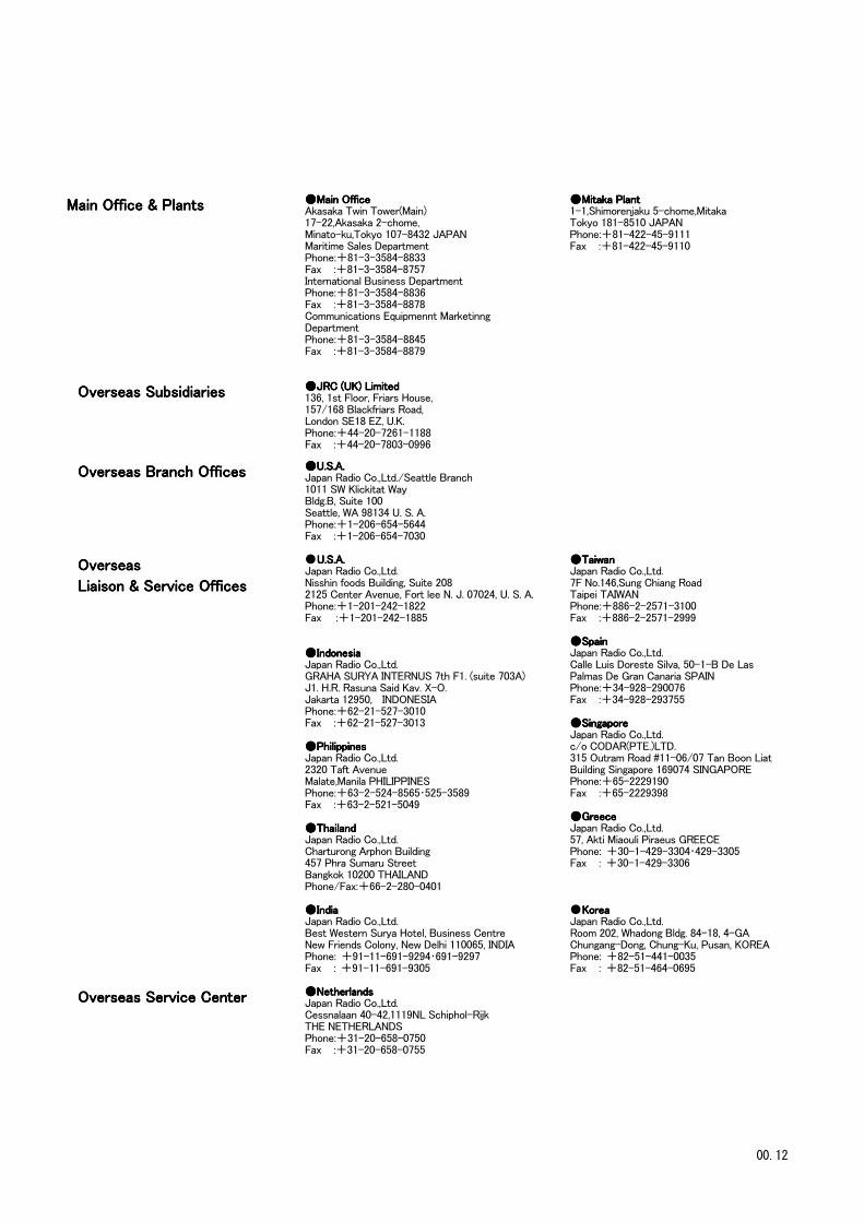
Main Office & PlantsMain Office & PlantsMain Office & PlantsMain Office & Plants ●●●●Main OfficeMain OfficeMain OfficeMain OfficeAkasaka Twin Tower(Main)17-22,Akasaka 2-chome,Minato-ku,Tokyo 107-8432 JAPANMaritime Sales DepartmentPhone:+81-3-3584-8833Fax :+81-3-3584-8757International Business DepartmentPhone:+81-3-3584-8836Fax :+81-3-3584-8878Communications Equipmennt MarketinngDepartmentPhone:+81-3-3584-8845Fax :+81-3-3584-8879
●●●●Mitaka PlantMitaka PlantMitaka PlantMitaka Plant1-1,Shimorenjaku 5-chome,MitakaTokyo 181-8510 JAPANPhone:+81-422-45-9111Fax :+81-422-45-9110
Overseas SubsidiariesOverseas SubsidiariesOverseas SubsidiariesOverseas Subsidiaries ●●●●JRC (UK) LimitedJRC (UK) LimitedJRC (UK) LimitedJRC (UK) Limited136, 1st Floor, Friars House,157/168 Blackfriars Road,London SE18 EZ, U.K.Phone:+44-20-7261-1188Fax :+44-20-7803-0996
Overseas Branch OfficesOverseas Branch OfficesOverseas Branch OfficesOverseas Branch Offices ●●●●U.S.AU.S.AU.S.AU.S.A....Japan Radio Co.,Ltd./Seattle Branch1011 SW Klickitat WayBldg.B, Suite 100Seattle, WA 98134 U. S. A.Phone:+1-206-654-5644Fax :+1-206-654-7030
OverseasOverseasOverseasOverseas
Liaison & Service OfficesLiaison & Service OfficesLiaison & Service OfficesLiaison & Service Offices
● U.S.AU.S.AU.S.AU.S.A....Japan Radio Co.,Ltd.Nisshin foods Building, Suite 2082125 Center Avenue, Fort lee N. J. 07024, U. S. A.Phone:+1-201-242-1822Fax :+1-201-242-1885
●●●●IIIIndonesiandonesiandonesiandonesiaJapan Radio Co.,Ltd.GRAHA SURYA INTERNUS 7th F1. (suite 703A)J1. H.R. Rasuna Said Kav. X-O.Jakarta 12950, INDONESIAPhone:+62-21-527-3010Fax :+62-21-527-3013
●●●●PhilippinesPhilippinesPhilippinesPhilippinesJapan Radio Co.,Ltd.2320 Taft AvenueMalate,Manila PHILIPPINESPhone:+63-2-524-8565・525-3589Fax :+63-2-521-5049
●●●●ThailandThailandThailandThailandJapan Radio Co.,Ltd.Charturong Arphon Building457 Phra Sumaru StreetBangkok 10200 THAILANDPhone/Fax:+66-2-280-0401
●●●●IndiaIndiaIndiaIndiaJapan Radio Co.,Ltd.Best Western Surya Hotel, Business CentreNew Friends Colony, New Delhi 110065, INDIAPhone: +91-11-691-9294・691-9297Fax : +91-11-691-9305
●●●●TaiwanTaiwanTaiwanTaiwanJapan Radio Co.,Ltd.7F No.146,Sung Chiang RoadTaipei TAIWANPhone:+886-2-2571-3100Fax :+886-2-2571-2999
●●●●SpainSpainSpainSpainJapan Radio Co.,Ltd.Calle Luis Doreste Silva, 50-1-B De LasPalmas De Gran Canaria SPAINPhone:+34-928-290076Fax :+34-928-293755
●●●●SingaporeSingaporeSingaporeSingaporeJapan Radio Co.,Ltd.c/o CODAR(PTE.)LTD.315 Outram Road #11-06/07 Tan Boon LiatBuilding Singapore 169074 SINGAPOREPhone:+65-2229190Fax :+65-2229398
●●●●GreeceGreeceGreeceGreeceJapan Radio Co.,Ltd.57, Akti Miaouli Piraeus GREECEPhone: +30-1-429-3304・429-3305Fax : +30-1-429-3306
● KoreaKoreaKoreaKoreaJapan Radio Co.,Ltd.Room 202, Whadong Bldg. 84-18, 4-GAChungang-Dong, Chung-Ku, Pusan, KOREAPhone: +82-51-441-0035Fax : +82-51-464-0695
Overseas Service CenterOverseas Service CenterOverseas Service CenterOverseas Service Center ●●●●NetherlandsNetherlandsNetherlandsNetherlandsJapan Radio Co.,Ltd.Cessnalaan 40-42,1119NL Schiphol-RijkTHE NETHERLANDSPhone:+31-20-658-0750Fax :+31-20-658-0755
00.12