foreword - harmony roof tiles€¦ · foreword harmony roof tiles has great pleasure in presenting...
TRANSCRIPT
HARMONY TECHNICAL SPECIFICATIONS
FOREWORD
Harmony Roof Tiles has great pleasure in presenting this Technical Manual to the industry andtake this opportunity to explain a little more about its background.
For a number of years, our company has been aware of the need to provide our clients with moredetailed information about fixing concrete roof tiles, that is to include information for bricklayers,roof carpenters and roof plumbers. We also realised the need to improve the assistance given toarchitects, engineers and designers by providing more detailed information for their designwork.
Although this manual has been published primarily for these reasons, other information hasbeen included such as product details of both tiles and accessories, standards and fixing
procedures.
We believe that this Technical Manual will go along way in answering all of your questionsconcerning performance and fixing of
Harmony Roof Tiles.

HARMONY TECHNICAL SPECIFICATIONS - 01/01/00 1
1. PRODUCTS AND ACCESSORIES (6 PAGES)1.1 Alpine .......................................................................................... 01/01/00 ........................... 11.2 Villa ............................................................................................. 01/01/00 ........................... 21.3 Shingle ........................................................................................ 01/01/00 ........................... 31.4 Ridge Cap .................................................................................... 01/01/00 ........................... 41.5 Rake Ridge .................................................................................. 01/01/00 ........................... 51.6 Finials .......................................................................................... 01/01/00 ........................... 6
2. AUSTRALIAN STANDARDS2.1 AS2049 - 1992 Manufacturing ............................................................................................ 12.2 AS2050 - 1995 Installation ................................................ (inc. ammendments 1&2) ...... 2
3. ROOF PITCHES AND REQUIREMENTS (2 PAGES)3.1 Roof Pitch Alpine and Villa ..................................................... 01/01/00 .......................... 13.2 Roof Pitch Shingle ..................................................................... 01/01/00 .......................... 2
4. CONSIDERATIONS FOR HIGH WIND AREAS (2 PAGES)4.1 Fixing Requirements ................................................................. 01/01/00 ........................... 14.2 Definitions of Fixing Methods ................................................. 01/01/00 ........................... 2
5. GENERAL ROOF PREPARATION (17 PAGES)5.1 Scaffolding and General Guard Rail Requirements ............... 01/01/00 .......................... 15.2 Preparatory Trades .................................................................... 01/01/00 .......................... 25.3 Flashing....................................................................................... 01/01/00 .......................... 35.3a Side Abutment Flashing .......................................................... 01/01/00 .......................... 35.3b Secret Flashing ........................................................................ 01/01/00 .......................... 35.3c Dutch Gable Flashing .............................................................. 01/01/00 ..................... 4 -55.4 Bedded Verge ............................................................................. 01/01/00 .......................... 65.5 Barge Board and Scribed Fillet ............................................... 01/01/00 .......................... 75.6 Fire Wall ..................................................................................... 01/01/00 .......................... 85.7 Rafter Spacings .......................................................................... 01/01/00 .......................... 95.8 Height of Tilt Board .................................................................. 01/01/00 ........................ 105.9 Exposed Rafters and Counter Battens ...................................... 01/01/00 ........................ 115.10 Valley Boards and Flashings .................................................. 01/01/00 ........................ 125.11 Box Gutter ................................................................................ 01/01/00 ........................ 135.11a Between two slopes ............................................................... 01/01/00 ........................ 135.11b To parapet wall ...................................................................... 01/01/00 ........................ 145.12 Discharge of Water from Upper Roof .................................... 01/01/00 ........................ 155.13 Change of Pitch ........................................................................ 01/01/00 ........................ 165.13a Less than 45° .......................................................................... 01/01/00 ........................ 165.13b More than 45° ........................................................................ 01/01/00 ........................ 17
CONTENTS
HARMONY TECHNICAL SPECIFICATIONS - 01/01/00 2
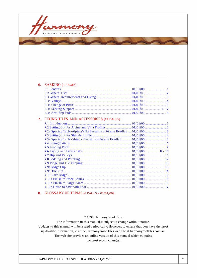
6. SARKING (8 PAGES)6.1 Benefits ....................................................................................... 01/01/00 .......................... 16.2 General Uses ............................................................................... 01/01/00 .......................... 26.3 General Requirements and Fixing ........................................... 01/01/00 .......................... 36.3a Valleys ....................................................................................... 01/01/00 .......................... 46.3b Change of Pitch ........................................................................ 01/01/00 .......................... 56.3c Sarking Support ....................................................................... 01/01/00 .................... 6 - 76.3d Anti-flap Pads .......................................................................... 01/01/00 .......................... 8
7. FIXING TILES AND ACCESSORIES (17 PAGES)7.1 Introduction ................................................................................ 01/01/00 .......................... 17.2 Setting Out for Alpine and Villa Profiles ............................... 01/01/00 .......................... 27.2a Spacing Table-Alpine/Villa Based on a 76 mm Headlap .... 01/01/00 .......................... 37.3 Setting Out for Shingle Profile ................................................ 01/01/00 .......................... 47.3a Spacing Table�Shingle Based on a 86 mm Headlap ........... 01/01/00 .......................... 57.4 Fixing Battens ............................................................................ 01/01/00 .......................... 67.5 Loading Roof .............................................................................. 01/01/00 .......................... 77.6 Laying and Fixing Tiles ............................................................ 01/01/00 .................. 8 - 107.7 Hip and Valleys ......................................................................... 01/01/00 ........................ 117.8 Bedding and Pointing ............................................................... 01/01/00 ........................ 127.9 Ridge and Tile Clipping ............................................................ 01/01/00 ........................ 137.9a Ridge Clip ................................................................................. 01/01/00 ........................ 137.9b Tile Clip .................................................................................... 01/01/00 ........................ 147.10 Rake Ridge ............................................................................... 01/01/00 ........................ 157.10a Finish to Brick Gables .......................................................... 01/01/00 ........................ 157.10b Finish to Barge Board ........................................................... 01/01/00 ........................ 167.10c Finish to Sawtooth Roof ....................................................... 01/01/00 ........................ 17
8. GLOSSARY OF TERMS (6 PAGES - 01/01/00)
© 1999 Harmony Roof TilesThe information in this manual is subject to change without notice.
Updates to this manual will be issued periodically. However, to ensure that you have the mostup-to-date information, visit the Harmony Roof Tiles web site at harmonyrooftiles.com.au.
The web site provides an online version of this manual which containsthe most recent changes.

HARMONY TECHNICAL SPECIFICATIONS - 01/01/00 1
1 PRODUCTS AND ACCESSORIES
1.1 Alpine
Construction: Extruded concrete interlocking roofing tile with fused or integral colour andclear sealer coat.
Manufactured to exceed the minimum requirements of AS2049�1992
Application: Roof and wall covering in pitch range of 12½°�90°
Weight: 4.8 kg (average)
Tiles per m2: (Nominal 76 mm head lap) 9.5

HARMONY TECHNICAL SPECIFICATIONS - 01/01/00 2
1.2 Villa
Construction: Extruded concrete interlocking roofing tile with fused or integral colour andclear sealer coat.
Manufactured to exceed the minimum requirements of AS2049�1992
Application: Roof and wall covering in pitch range of 12½°�90°
Weight: 4.8 kg (average)
Tiles per m2: (Nominal 76 mm head lap) 9.5
1 PRODUCTS AND ACCESSORIES
HARMONY TECHNICAL SPECIFICATIONS - 01/01/00 3
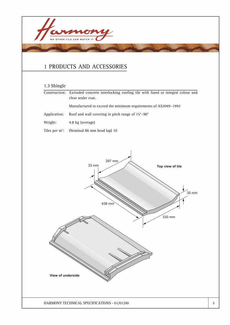
1.3 Shingle
1 PRODUCTS AND ACCESSORIES
Construction: Extruded concrete interlocking roofing tile with fused or integral colour andclear sealer coat.
Manufactured to exceed the minimum requirements of AS2049�1992
Application: Roof and wall covering in pitch range of 15°�90°
Weight: 4.8 kg (average)
Tiles per m2: (Nominal 86 mm head lap) 10

HARMONY TECHNICAL SPECIFICATIONS - 01/01/00 4
1.4 Ridge Cap
Construction: Extruded concrete with fused or integral colour and clear sealer coat. Manufacturedto exceed the minimum requirements of AS 2049�1992.
Application: Capping Ridges and Hips
Weight: 4.6 kg (average)
Tiles per lineal metre: 2.5
1 PRODUCTS AND ACCESSORIES

HARMONY TECHNICAL SPECIFICATIONS - 01/01/00 5
1.5 Rake Ridge
Construction: Hand made moulded concrete with fused or integral colour and clear sealer coat.
Application: Gables, Verges and Skillions
Weight: 4.0 kg (average)
Tiles per lineal metre: 2.5
1 PRODUCTS AND ACCESSORIES

HARMONY TECHNICAL SPECIFICATIONS - 01/01/00 6
1.6 Finials (Scroll Type)
1 PRODUCTS AND ACCESSORIES
Application: For Gable ends or Dutch Gables

HARMONY TECHNICAL SPECIFICATIONS - 01/01/00 1
2.1 AS2049 - 1992 Manufacturing
2. AUSTRALIAN STANDARDS

HARMONY TECHNICAL SPECIFICATIONS - 01/01/00 2
2.2 AS2050 - 1995 Installation
2. AUSTRALIAN STANDARDS

HARMONY TECHNICAL SPECIFICATIONS - 01/01/00 1
3. ROOF PITCHES AND REQUIREMENTS
3.1 Roof Pitch Alpine and Villa
HARMONY TECHNICAL SPECIFICATIONS - 01/01/00 2
3. ROOF PITCHES AND REQUIREMENTS
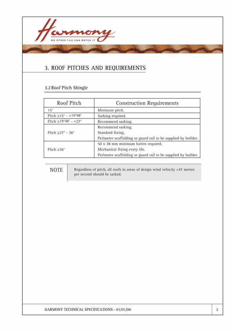
3.2 Roof Pitch Shingle

HARMONY TECHNICAL SPECIFICATIONS - 01/01/00 1
4. CONSIDERATIONS FOR HIGH WIND AREAS
4.1 Fixing Requirements
Australian Standard AS2050�1995 specifies particular fixing requirements in respect to highwind areas.
To ensure these requirements are met, the owner, builder or designer must notify Harmony RoofTiles of the correct category as listed below:
Harmony
Category
Rating
Design
Wind
Velocitym/s
Tile Fixing Ridge Fixing Barge
Fixing
Edge of
Roof
Field of
Roof Tiles
Hip Fixing
Category 1
Up to but not
including 33
Mechanically fix each full tile
in 2nd course and theneither every 2nd tile in everycourse, or every tile in every
2nd course.
Mechanically
fix the endfour ridge
tiles
Nil Mechanically
fix eachbarge tile
Category 2
From 33 upto but not
including 41
Mechanicallyfix each full
tile in 2ndcourse
Mechanicallyfix each 2nd
full tile
Mechanicallyfix every
ridge tile
Mechanicallyfix the end
four hipridge tiles
Mechanicallyfix each
barge tile
Category 3
From 41 up
to andincluding 60
Mechanically
fix every fulltile
Mechanically
fix every fulltile
Mechanically
fix everyridge tile
Mechanically
fix every hipridge tile
Mechanically
fix eachbarge tile
Reproduced with permission from AS 2050/Amdt 1/1995-09-05
HARMONY TECHNICAL SPECIFICATIONS - 01/01/00 2
4. CONSIDERATIONS FOR HIGH WIND AREAS
4.2 Definitions of Fixing Methods
Mechanical fixing of roof tiles: a) nails or tile clips
Mechanical fixing of ridge capping: a) ridge clipsb) hip clipsc) polymer based pointing mortar - complying toAustralian Standards AS 2050�1995

HARMONY TECHNICAL SPECIFICATIONS - 01/01/00 1
5. GENERAL ROOF PREPARATION
5.1 Scaffolding and General Guard Rail Requirements
Edge Protection - Identified Minimum Industry Standards.
A person who erects or dismantles a guard rail system or perimeter scaffold, must ensure that theerection or dismantling, as the case may be, is done in accordance with Regulations 3.67 andAS1576 parts 1 to 5.
When scaffolding exceeds, or is likely to exceed, a height of 4m it must be erected, alltered ordismantled by a certified scaffolder.
* Reproduced with permission from the Code of Safe Work Practice for the Roof Tiling
Industry - WA
ERUTCURTSFOOR TNEMERIUQERMUMINIM
thgiehsevaehtiwsfoorllA.1dnuorgmorfm3evobarota
level
nahtrewolondloffacsretemirepro/dnametsysliardrauGaicsafehtmorfmm009
°5.72tadehctipsfoorllA.2°23nahtssel
nahtrewolondloffacsretemirepro/dnametsysliardrauG.acisafehtmorfmm009
rotadehctipstoorllA.3°23evoba
yamsnoitaveleemoS.thgiehaicsaftadloffacsretemirePfoorehtnihtiwmroftalpgnikrowlanoitiddaeriuqer
sasretfarfohctipdnahtgnelottcejbuserutcurts.tnemssessaytefasetisaybdenimreted
wolebsfooryerotsowtllA.4°5.72
nahtrewolondloffacsretemirepro/dnametsysliardrauGaicsafehtmorfmm009
rotasfooryerotsowtllA.5°5.72evoba
yamsnoitaveleemoS.thgiehaicsaftadloffacsretemirePfoorehtnihtiwmroftalpgnikrowlanoitiddaeriuqer
sasretfarfohctipdnahtgnelottcejbuserutcurts.tnemssessaytefasetisaybdenimreted
owtgnideecxesfoorllA.6yerots
yamsnoitaveleemoS.thgiehaicsaftadloffacsretemirePfoorehtnihtiwmroftalpgnikrowlanoitiddaeriuqer
sasretfarfohctipdnahtgnelottcejbuserutcurts.tnemssessaytefasetisaybdenimreted
yreppilslaitnetopynA.7,.g.e(°51evobarotatcudorplatem,ssalgerbif,tnemecorbif
)stcudorpfoor
nahtrewolondloffacsretemirepro/dnametsysliardrauGetisaeriuqeryam°51wolebsfooR.aicsafehtmorfmm009
.tnemssessaytefas
htiw"sdioVlanretnI"llA.8morferomrom3follafeerf
noitavelefoor
otllafeerfdecuderotmroftalpgnikrowdetcereyllanretnI.m2nahtssel
noitavelefoorasi"dioVlanretnI"nafonoitinifeD:etoN.gniliecdekarrolardehtacasahtaht

HARMONY TECHNICAL SPECIFICATIONS - 01/01/00 2
5. GENERAL ROOF PREPARATION
5.2 Preparatory Trades
The relevant trades must have performed the following preparatory work before any tiles can belaid.
Brickwork� All relevant brickworks complete.
Carpenter� Ridge and hip boards fixed flush with rafters.
� Fascia (or tilt batten) fitted.
� Barge board fitted.
� Verge strip fitted (if required for bedding).
� Gable sheeting and flashing fitted for dutch gables.
� Anti-ponding boards fitted (if required).
� Lining boards and counter-battens fitted (for exposed rafters).
Plumber� Valley irons and gutters fitted.
� Secret gutters and flashings fitted (if required).
HARMONY TECHNICAL SPECIFICATIONS - 01/01/00 3
5. GENERAL ROOF PREPARATION
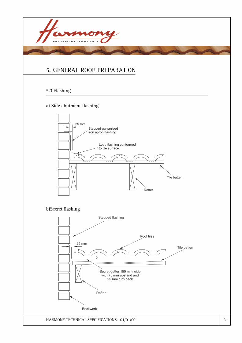
5.3 Flashing
a) Side abutment flashing
b)Secret flashing

HARMONY TECHNICAL SPECIFICATIONS - 01/01/00 4
5.3 Flashing
c) Dutch Gable Flashing
Dutch gable over flashing should extend the entire width of the gable. It should finish over thetop of the hip rafters.
a) Side view.
5. GENERAL ROOF PREPARATION

HARMONY TECHNICAL SPECIFICATIONS - 01/01/00 5
5. GENERAL ROOF PREPARATION
5.3 Flashing
c) Dutch Gable Flashing
b) Top view.

HARMONY TECHNICAL SPECIFICATIONS - 01/01/00 6
5. GENERAL ROOF PREPARATION
5.4 Bedded Verge
Brickwork on the gable ends should finish flush to the under side of the tile batten and should becut to a straight level line over the full length of the gable. When tiles are to be bedded on top ofthe brickwork, a header course of bricks on top of the cut course gives a neater, professionalfinish.
In an exposed beam construction, where ceilings are fixed on top of the rafters, an allowanceshould be made for the extra height.

HARMONY TECHNICAL SPECIFICATIONS - 01/01/00 7
5. GENERAL ROOF PREPARATION
5.5 Barge Board and Scribed Fillet
The barge board should be fixed so that it is level with the top of the tile battens. This will holdthe tile level and allow secure fixing of the verge tiles and will also allow the secure fixing of ascribed filet where one is to be used. Barge boards are fitted before the tiles and scribed fillets arefitted after the tiles.

HARMONY TECHNICAL SPECIFICATIONS - 01/01/00 8
5. GENERAL ROOF PREPARATION
5.6 Fire Wall
There should be a 75 mm gap between the top of the finished brickwork and the top of the rafter.This will provide a space for the insertion of a non-combustible fire blanket without affecting theline of the roof. The tile battens should not cross over the fire wall but should be cut flush withthe edge of the brickwork. The galvanised steel strap should overlap the fire wall by a minimumof 120 mm.
HARMONY TECHNICAL SPECIFICATIONS - 01/01/00 9
5. GENERAL ROOF PREPARATION
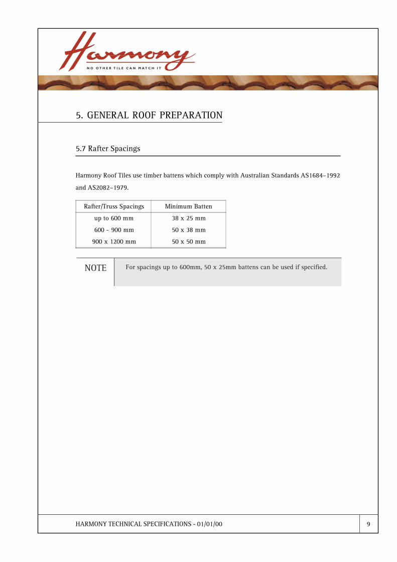
5.7 Rafter Spacings
Harmony Roof Tiles use timber battens which comply with Australian Standards AS1684�1992
and AS2082�1979.
Rafter/Truss Spacings Minimum Batten
up to 600 mm 38 x 25 mm
600 - 900 mm 50 x 38 mm
900 x 1200 mm 50 x 50 mm

HARMONY TECHNICAL SPECIFICATIONS - 01/01/00 10
5. GENERAL ROOF PREPARATION
5.8 Height of Tilt Board
The fascia board or tilt batten and the gutter should be fixed by the builder before tiling commences.The thickness of the tile battens govern the height of the tilt batten or fascia. As shown in theillustration below, the �upstand� should equal the thickness of the tile batten plus 25 mm.

HARMONY TECHNICAL SPECIFICATIONS - 01/01/00 11
5. GENERAL ROOF PREPARATION
5.9 Exposed Rafters and Counter Battens
In this type of ceiling construction, where the ceiling is fixed on top of exposed roof rafters, thereare some requirements that need to be completed before tiling can begin. Counter battens mustbe positioned accurately over the rafter centre lines on top of the lining board and the sarkingmembrane attached to these battens. The counter battens should be thick enough,(around 50 mm x 13 mm), to allow the sarking to dish correctly in accordance with AS/NZS4200.2-1994.

HARMONY TECHNICAL SPECIFICATIONS - 01/01/00 12
5. GENERAL ROOF PREPARATION
5.10 Valley Boards and Flashings
Valley Gutter
There are accepted practices covering the construction of valley gutters. The width of the materialused to constuct a standard valley tray should not be less than 400 mm and joins must beoverlapped by not less than 100 mm in the direction of the flow.
Care should be taken to ensure that the valley gutter is not bent or flattened out on internalangles at the eaves gutter.
Recess Valley GutterA recess valley gutter usually forms a recess between the two sides of the valley tray into thevalley rafter.
They should be used when;
a) A valley exceeds 8.0 m in length thus coping with excess water volume.
b) A dog leg occurs in roof design. This will help guide the flow of water around the bend and prevent overspill.
c) Two different pitched roofs meet. To stop overflow, the wider side forming the recess valley should be between 300 mm and 450 mm and placed on the lesser pitched roof side.
Valley BoardsThe valley board should be 5mm thinner than the tile battens. This will prevent damage to theturned edge of the valley flashing.
Valley boards should be checked into the back of the tilt or fascia to ensure an even line at theinternal angles and support the valley flashing where it enters the eaves gutter.
HARMONY TECHNICAL SPECIFICATIONS - 01/01/00 13
5. GENERAL ROOF PREPARATION
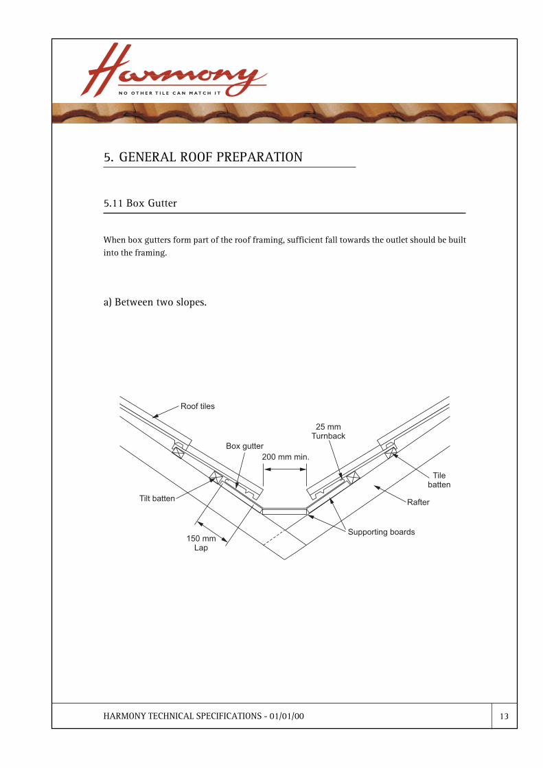
5.11 Box Gutter
When box gutters form part of the roof framing, sufficient fall towards the outlet should be builtinto the framing.
a) Between two slopes.
HARMONY TECHNICAL SPECIFICATIONS - 01/01/00 14
5. GENERAL ROOF PREPARATION
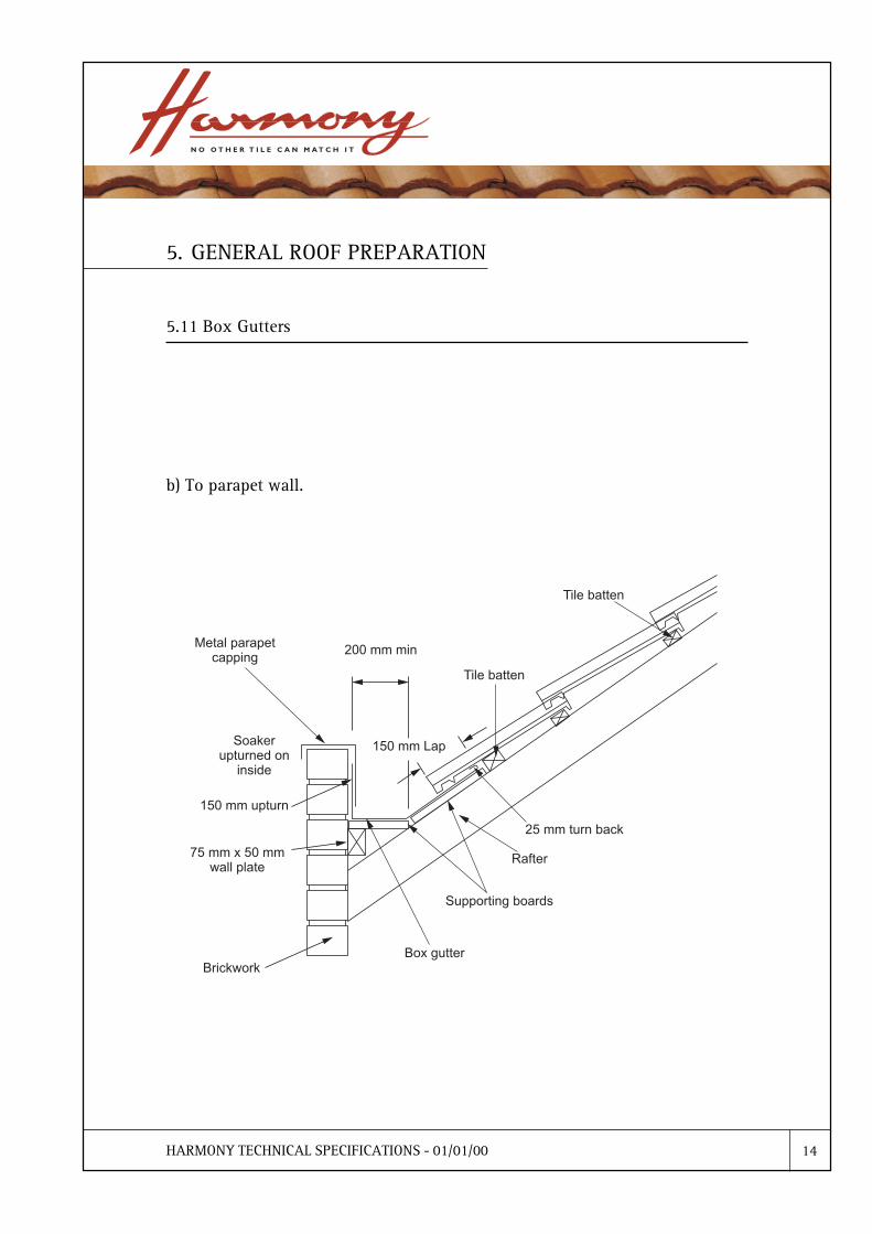
5.11 Box Gutters
b) To parapet wall.

HARMONY TECHNICAL SPECIFICATIONS - 01/01/00 15
5. GENERAL ROOF PREPARATION
5.12 Discharge of Water from Upper Roof
The discharge of water from upper roofs, through downpipes directly onto tiled roofs, should beavoided. However, in cases where water is discharged onto a tiled roof, the following requirementsare necessary:� A spreader must be used at the base of the downpipe. The spreader must be sealed at both
ends to prevent water discharge into the side lap of the tile.� Under the spreader an outer flashing (usually lead) should be installed and dressed into the
profile of the roof tile.� The roof area below the spreader should be sarked for a minimum width of 1800 mm either
side from the point of discharge and extended down to the eaves gutter or valley.

HARMONY TECHNICAL SPECIFICATIONS - 01/01/00 16
5. GENERAL ROOF PREPARATION
5.13 Change of Pitch
a) Less than 45°

HARMONY TECHNICAL SPECIFICATIONS - 01/01/00 17
5. GENERAL ROOF PREPARATION
5.13 Change of Pitch
b) More than 45°
HARMONY TECHNICAL SPECIFICATIONS - 01/01/00 1
6.1 Benefits
The recommended material for use as sarking is a Reflective Foil Laminate which provides weather-proofing as well as insulation. It has a high reflection and low emission factors for low temperature(thermal) radiation found within buildings.
The Reflective Foil Laminate is a flexible sheet material which is supplied as a roll. It is installedover the rafters, under the tile battens and has many benefits to offer when used under the roofcovering. Sarking reflective foil insulation material should be a double sided, anti-glare typewith a maximum flammability index of 5 in accordance with AS/NZS 4200.1-1994 .
Using reflective foil laminate as a sarking material is recommended because of its excellentinsulating and weatherproofing properties. Sarking reduces approximately 90% of radiant heatin the summer and between 30% to 40% heat loss in the winter. It has excellent water proofingqualities and when installed properly prevents damage occurring to ceiling materials and interiorfixtures and fittings.
Sarking eliminates dust intrusion and reduces sound penetration. It also helps prevent fire, froman outside source, igniting inside the roof space. Its use is highly recommended in buidingswhich are located in high risk bush fire areas.
When wind gusts occur, sarking reduces the impact of uplift forces on the roof tiles.
6. SARKING

HARMONY TECHNICAL SPECIFICATIONS - 01/01/00 2
6. SARKING
6.2 General Uses
You should fix Sarking under the following circumatances:
• Where local or building regulations dictate the use of sarking.
• Where local conditions include a high risk of wind driven rain.
• Where the roof design means water is discharged from an upper storey.
• Where the roof design includes exposed rafters with top lining.
• Where the roof pitch is 15° or less (Alpine and Villa profile).
• Where the roof pitch is 19° 47´ or less (Shingle profile).
• Areas of design wind velocity greater than 47 metres/second.

HARMONY TECHNICAL SPECIFICATIONS - 01/01/00 3
6. SARKING
6.3 General Requirements and Fixing
As we have read at the beginning of this section on sarking, the membrane is installed under theroof covering and its main pupose is to collect and dispose of any water which may penetrate theroof covering. The Australian Standard AS/NZS 4200.2-1994, which is the standard for �PliableBuilding Membranes and Underlays�, contains detailed information about how the sarkingmembrane should be fixed.
Great care should be taken to ensure that the sarking membrane is fixed correctly otherwise itseffectiveness is limited. Likewise, similar care should be taken not to damage the membraneduring fixing.
Sarking is laid across the roof rafters with each run overlapping the previous run below it by aminimum of 50 mm. Allow a �one rafter space� overlap where a vertical joint of the membrane isrequired. To ensure adequate drainage, the sarking should be layed between adjacent rafters andfixed under the tile battens. It should sag no more than the depth of the supporting batten(counter batten) and in no case is the sag to exceed 40 mm.
Extend the membrane by about 50 mm over the facia and secure firmly to the top edge of thefacia. Make sure that the membrane is extended over the facia enough to ensure effective waterrun-off. When fixing the sarking at the ridge line, carry the membrane over the ridge board.

HARMONY TECHNICAL SPECIFICATIONS - 01/01/00 4
6. SARKING
6.3a Valleys
When working on a sarked roof, it is important to note that the sarking material must not be laidinto the valley gutter. A tile batten (valley batten) should be fixed along each side of the valleyboard around 15 mm away from the board. The sarking membrane should then be turned overaround the batten.

HARMONY TECHNICAL SPECIFICATIONS - 01/01/00 5
6. SARKING
6.3b Change of Pitch
When there is a change of pitch between two roofs, sarking should be fixed to the lower roof ifit has a pitch of less than the minimum requirements (see sections 3.1 and 3.2). Under thesecircumstances the sarking under the lower roof must extend at least 350 mm into the higherpitched main roof. The sarking should be fixed to the lowest batten of the upper roof section andcontinue over the whole of the lower section.
Where sarking is also to be fixed on the upper part of the roof, the overlap to the lower roofsection should be at least 150 mm.
HARMONY TECHNICAL SPECIFICATIONS - 01/01/00 6
6. SARKING
6.3c Sarking Support
a) Mesh
The Australian Standard AS/NZS 4200.1-1994 recommends that the �sarking membrane shouldbe supported by wire mesh or be otherwise adequately reinforced� on a roof constructionwhere the distance from one rafter centre to the next is between 600 mm and 900 mm. If thedistance between rafter centres exceeds 900 mm, this recommendation becomes a requirementof the Standard.

HARMONY TECHNICAL SPECIFICATIONS - 01/01/00 7
6. SARKING
6.3c Sarking Support
b) Anti-ponding Board
On a roof construction with a pitch below 19° 48´, the use of anti-ponding boards isrecommended. The boards are installed to support sarking and ensure that any water collectedby the sarking is correctly discharged into the eaves gutters.
The builder will be required to install this anti-ponding protection which usually consists offibre cement sheeting or similar materials.
The anti-ponding board should be 225 mm in width and must leave a clear space to the firsttile batten.
HARMONY TECHNICAL SPECIFICATIONS - 01/01/00 8
6. SARKING
6.3d Anti-flap Pads
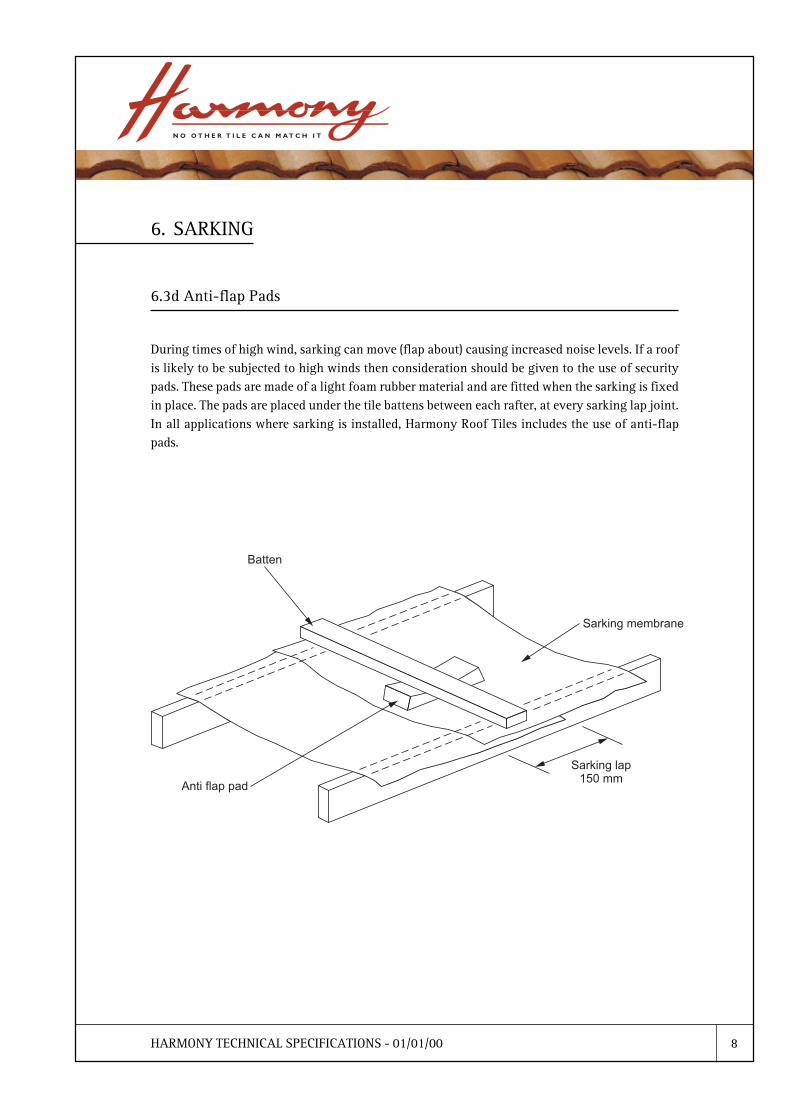
During times of high wind, sarking can move (flap about) causing increased noise levels. If a roofis likely to be subjected to high winds then consideration should be given to the use of securitypads. These pads are made of a light foam rubber material and are fitted when the sarking is fixedin place. The pads are placed under the tile battens between each rafter, at every sarking lap joint.In all applications where sarking is installed, Harmony Roof Tiles includes the use of anti-flappads.

HARMONY TECHNICAL SPECIFICATIONS - 01/01/00 1
7. FIXING TILES AND ACCESSORIES
7.1 Introduction
Introduction
The Australian Standard AS2050�1995 covers the laying and securing of roof tiles.
Precautions
The Australian Standard AS2050�1995, Appendix A and Appendix B states that the correctnessand safety of the building is the responsibility of the builder.
Loading
Battening and sarking of the entire roof must be completed before tiles are loaded. In buildingswhere the rafters are internally exposed, or the length of the truss top chord or rafter exceeds6 metres, tiles should be loaded onto the structure from each side to ensure that their weightis evenly distributed.
First Course
The first course of tiles should be positioned to provide an adequate projection (around50mm) over the fascia and into the gutter.
Mechanical Fixing
Because of variation in work practice between States, this document uses the term �mechanicallyfix� to describe the activity of nailing and clipping tiles (refer to Section 4.2).
Fixing Materials
Nails should be non-ferrous or galvanised with a minimum diameter of 2.8mm. They shouldbe of sufficient length to penetrate the batten by at least 15mm.
Steep Pitch Fixing
For pitches 36° and over, all tiles shall be mechanically fixed.
Minimum Fixing Requirements
Refer to section 3.1 and 3.2 for information about the minimum fixing requirements for tilesand accessories

HARMONY TECHNICAL SPECIFICATIONS - 01/01/00 2
7. FIXING TILES AND ACCESSORIES
7.2 Setting Out for Alpine and Villa Profiles
To obtain a uniform appearance of the completed tile courses, correct spacing of the tile battensis essential. To obtain this uniformity follow the procedure detailed below.
1 Measure the distance from the front edge of the fascia or tilting batten to 25 mm from face ofridgeboard.
2 In the spacing table (see section 7.2a) , find the dimension nearest to this measurement andthen note the dimension at the head of the particular column in the table. This is the requireduniform course spacing. Bear in mind that 362 mm is the maximum permissible coursespacing.
3 Mark off both ends of the roof at a point 355 mm from front edge of fascia board or tiltbatten. Mark off from this point up the remainder of the rafter using the uniform coursespacing obtained from the table or adjusted slightly if necessary so as to obtain equal incrementsfinishing 25 mm from face of ridgeboard.
4 Snap a chalk line across the top of the roof framing.
5 Locate lower edge of battens on chalk lines and nail to roof framing.

HARMONY TECHNICAL SPECIFICATIONS - 01/01/00 3
7. FIXING TILES AND ACCESSORIES
7.2a Spacing Table�Alpine/Villa (Based on a 76 mm Headlap)

HARMONY TECHNICAL SPECIFICATIONS - 01/01/00 4
7.3 Setting Out for Shingle Profile
To obtain a uniform appearance of the completed tile courses, correct spacing of the tile battensis essential. To obtain this uniformity follow the procedure detailed below.
1 Measure the distance from the front edge of the fascia or tilting batten to 25 mm from face ofridgeboard.
2 In the spacing table (see section 7.3a) , find the dimension nearest to this measurement andthen note the dimension at the head of the particular column in the table. This is the requireduniform course spacing. Bear in mind that 352 mm is the maximum permissible coursespacing.
3 Mark off both ends of the roof at a point 355 mm from front edge of fascia board or tiltbatten. Mark off from this point up the remainder of the rafter using the uniform coursespacing obtained from the table or adjusted slightly if necessary so as to obtain equal incrementsfinishing 25 mm from face of ridgeboard.
4 Snap a chalk line across the top of the roof framing.
5 Locate lower edge of battens on chalk lines and nail to roof framing.
7. FIXING TILES AND ACCESSORIES

HARMONY TECHNICAL SPECIFICATIONS - 01/01/00 5
7.3a Spacing Table�Shingle (Based on a 86 mm Headlap)
7. FIXING TILES AND ACCESSORIES

HARMONY TECHNICAL SPECIFICATIONS - 01/01/00 6
7.4 Fixing Battens
The battens should be laid out over the setting out nails and cut to size. All joints should besquare and cut to the centre of the rafter or truss. Joins should be staggered throughout the roofwith no two joins occurring on the same rafter or truss in adjacent courses.
All tile battens should be nailed to each rafter or truss with at least one nail of sufficient lengthto penetrate the rafter or truss by the thickness of the tile batten being used, eg 50mm x 25mmbatten require 25mm penetration.
If a cut course has occurred in the setting out, the tile batten should be angled to support the tileon the same plane as the rest of the roof.
7. FIXING TILES AND ACCESSORIES
sgnicapSssurT/retfaR nettaBmuminiM
mm006otpu mm52x83
mm009-006 mm83x05
mm0021x009 mm05x05

HARMONY TECHNICAL SPECIFICATIONS - 01/01/00 7
7. FIXING TILES AND ACCESSORIES
7.5 Loading Roof
The pitch of the roof has to be considered when loading the roof.
Roof Pitch Less Than 30°
The roofing tiles should be carried onto the roof in �lifts� of six to eight tiles. Each lift should bedeposited on the tile batten, with the nose of the bottom tile hooked over the tile batten, and theback of the tile sitting on the batten below. Each tile in the lift should have the nose of the tilehooked over the one below.
The lifts should be spaced approximately 900mm apart over the entire roof, with an extra lift atthe hip or gable to allow for cutting and wastage.
On trusses or roofs designed with a camber to take up the load, it may be a requirement that theroof be loaded equally on both sides to spread the weight evenly.
Roof Pitch Between 30° and 40°
The loading of these steep pitched roofs requires special attention. Safety must be of foremostimportance to prevent the tiles slipping and falling from the roof.
The following method will provide for satisfactory placement of lifts before the spreading operation.
The method for loading roofs below 30° is used with exception that one batten is left free and thelifts are placed 450mm apart. It is then possible to slit the lift into two. The top half of the lift ishooked over the nose of the tile over the free batten and the back of the tile rested on the split liftbelow.
Roof Pitch More Than 40°
On very steep pitched roofs loading of the roof should not exceed the amount of tiles that can belaid and fixed in that days work.
All loose material should be removed from the roof for safety reasons.

HARMONY TECHNICAL SPECIFICATIONS - 01/01/00 8
7. FIXING TILES AND ACCESSORIES
7.6 Laying and Fixing Tiles
Tiles should be laid in accordance with AS 2050�1995. All courses of tiles should be alignedhorizontally, vertically and diagonally in order to ensure that the roof presents a regular andeven appearance. The tiles can be laid in either straight or broken bond. Where possible, the tilesshould be fitted close together, (but not hard together) and should be parallel to one another.However, all tiles may be �slack jointed� to compensate for the roof being out of square and toensure gable ends finish with either full or cut half tiles.
The maximum slack joint gap should be 15mm.
Tiles are always laid from right to left, commencing at the eaves course.

HARMONY TECHNICAL SPECIFICATIONS - 01/01/00 9
7. FIXING TILES AND ACCESSORIES
7.6 Laying and Fixing Tiles
Setting-out
It is important to �
a) Obtain straight lines at sidelaps
b) Avoid narrow cut tiles at verges
c) Ensure that tiles at verges are parallel to the verge
Mark ridge and eaves at equal intervals of three tiles plus where necessary an allowance foradjusting each tile joint to compensate for a difference between �A� and �B� and to finish with ahalf or full tile at each verge. Join marks with chalk line as shown.

HARMONY TECHNICAL SPECIFICATIONS - 01/01/00 10
7. FIXING TILES AND ACCESSORIES
7.6 Laying and Fixing Tiles

HARMONY TECHNICAL SPECIFICATIONS - 01/01/00 11
7. FIXING TILES AND ACCESSORIES
7.7 Hip and Valleys
Tile cutting is carried out by using pincers or a tile cutter designed to suit the tile material.
All tiles should be cut cleanly and to suit the angle of the roof.
Hip tiles should be cut to the centre of the hip rafter, there should be no more than a 13 mm gapbetween the starting and finishing sides of the hip.
To hold the cut tiles on the hip level with the full tile it is necessary to drive a nail of sufficientlength into the hip rafter, then bend the nail under the cut tile to hold the cut tile level with thefull tile.
Valley tiles should be cut no wider that 75 mm between the two planes of the roof. The tilesshould overhang the valley gutter by no less than 100 mm.

HARMONY TECHNICAL SPECIFICATIONS - 01/01/00 12
7. FIXING TILES AND ACCESSORIES
7.8 Bedding and Pointing
Preparation
Before the bedding and final touches are completed on the roof it is important that the roof bechecked and all the necessary preliminary work completed.
All debris should be removed and tiles broken during fixing replaced.
Bedding and pointing of the accessories is carried out in two operations.
Stage One
Tiles and accessories that required bedding are fixed with a mortar mix of one part masonrycement or similar to four parts clean sand (brickies sand is the most suitable).
Stage Two
Bedding that requires pointing or areas that require pointing only are normally finished with amortar mix of one part portland cement to three parts clean sand, with oxide or similar colouringagent introduced into the mix to suit the colour of the tile.
If required and/or specified, an approved polymer based pointing mortar can be used. Thisproduct is usually available pre-mixed and colour matched to any roof tile.
Bedding and pointing operations should not be carried out in extreme conditions. During periodsof high temperatures the accessories should be thoroughly wetted before use.
Under no circumstances should any type of additive be added to the mixes.

HARMONY TECHNICAL SPECIFICATIONS - 01/01/00 13
7. FIXING TILES AND ACCESSORIES
7.9 Ridge and Tile Clipping
a) Ridge Clip
The ridge clip is designed to secure each ridge piece to both ridge and hip boards. The topof the ridge clip is fitted on the middle edge of the ridge piece and the bottom part ishooked on to a wire that is secured along the length of the ridge or hip board at one metreintervals. The wire should be firmly taut at each secured point.
HARMONY TECHNICAL SPECIFICATIONS - 01/01/00 14
7. FIXING TILES AND ACCESSORIES
7.9 Ridge and Tile Clipping
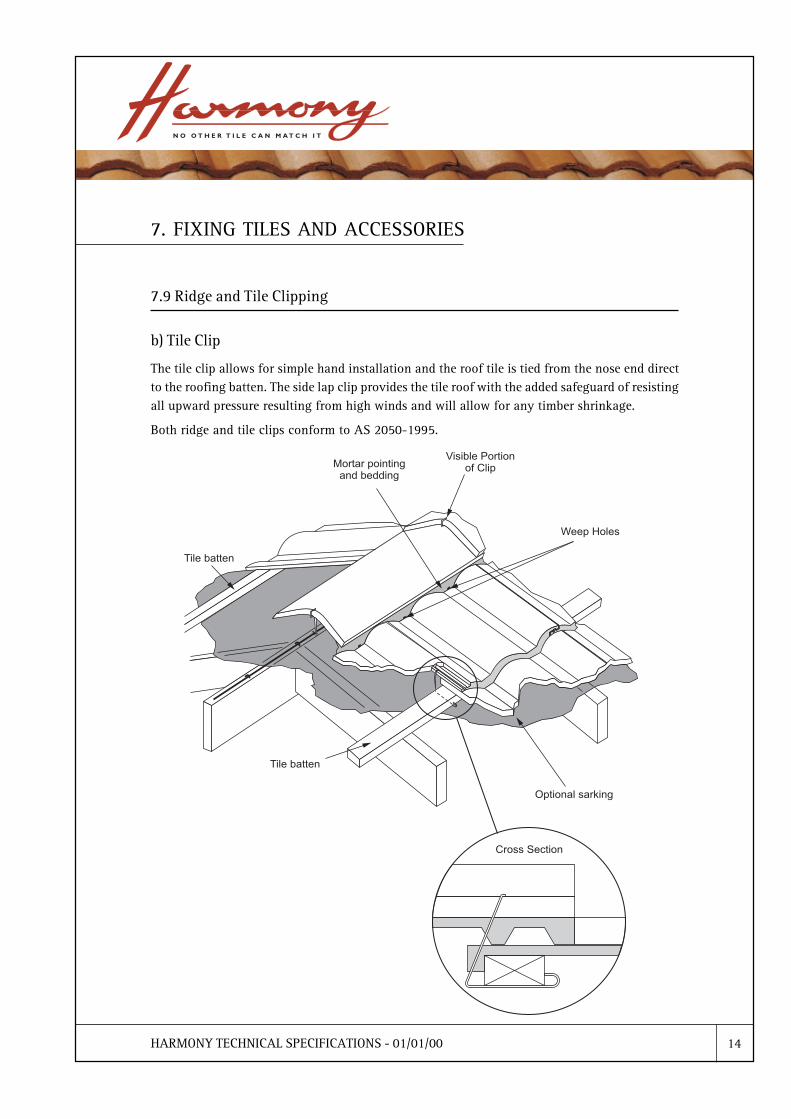
b) Tile Clip
The tile clip allows for simple hand installation and the roof tile is tied from the nose end directto the roofing batten. The side lap clip provides the tile roof with the added safeguard of resistingall upward pressure resulting from high winds and will allow for any timber shrinkage.
Both ridge and tile clips conform to AS 2050-1995.
HARMONY TECHNICAL SPECIFICATIONS - 01/01/00 15
7. FIXING TILES AND ACCESSORIES
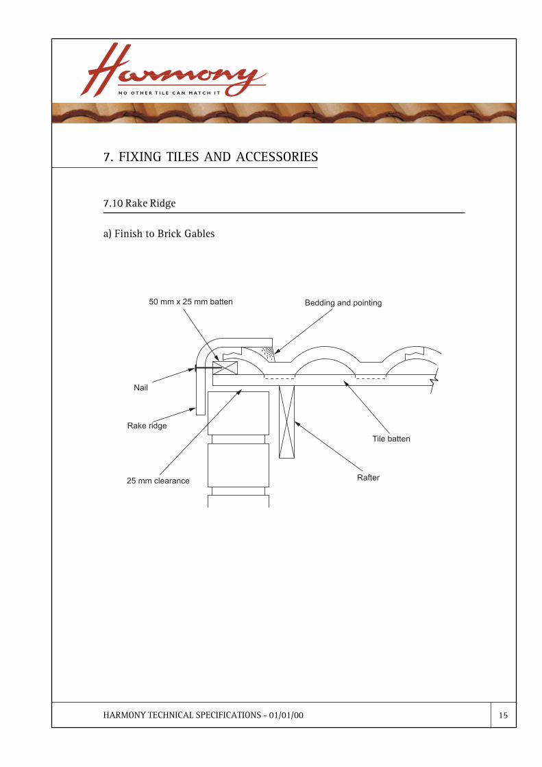
7.10 Rake Ridge
a) Finish to Brick Gables

HARMONY TECHNICAL SPECIFICATIONS - 01/01/00 16
7. FIXING TILES AND ACCESSORIES
7.10 Rake Ridge
b) Finish to Barge Board

HARMONY TECHNICAL SPECIFICATIONS - 01/01/00 17
7. FIXING TILES AND ACCESSORIES
7.10 Rake Ridge
c) Finish to Sawtooth Roof

HARMONY TECHNICAL SPECIFICATIONS - 01/01/00 1
GLOSSARY OF TERMS
Abutment
The junction of a roof with a structure which rises above it.
Accessory
A concrete or terracotta product used to finish a roof; includes ridge, barge tiles and finials
Anti-Ponding Board
A sarking support which bridges the top of the fascia board (or tilting batten) and the rafters.They are used to prevent water building up (ponding) behind the fascia.
Apex
The intersection of all ascending hips where they meet either a ridge or another ascendinghip.
Barge Board
A dressed timber (can be metal) member fixed along the pitched edges of a gable which isused to cover the ends of the roof members.
Batten
A small section of timber or steel which provides a means of supporting, positioning orfixing tiles. The following are examples of batten types:
Tile batten � a batten parallel to the eaves line and at right angles to the rafters. Sometimescalled nailing strip or furring strip. Tiles are fixed to it.
Counter batten � a batten fixed on top of the rafters to allow sarking to sag where ceilinglining (with exposed beams) is used.
Tilting batten (bellcast) � a batten fixed to the eaves end of a pitched roof to maintain theroof slope at the eaves course. The fascia board is usually used for this purpose.
Bedding
The fixing of tiles, ridging or hip capping upon a bed or mortar. This is also the term used forthe mix of builder�s sand and mortar used to fix tiles .
Note: edges are finished off by �pointing�.
Bond
The system of aligning tiles on the roof in relationship to each other. With straight bond thesides of tiles form straight lines from bottom to top course. With staggered, broken or crossbond, tiles in each alternate course overlap, by half, the tiles above and below them.
Dormer
A vertical window formed in a slopping roof.

HARMONY TECHNICAL SPECIFICATIONS - 01/01/00 2
GLOSSARY OF TERMS
Eaves
The lower parts of a roof which project beyond the face of the external walls.
Eaves Overhand
The inclined distance (line of rafter) from the external load-bearing wall to the fascia.
Eaves Width
The horizontal dimension between the inside of the fascia board and the outside of theexternal wall.
Edge of Roof
The area of a roof bounded by the eaves, ridge and barge, extending towards the centre of theroof for a distance equal to 0.1 multiplied by the minimum plan dimension of the building,measured from eaves to eaves or barge to barge.
Fascia Board
A member, usually of timber, fixed to the rafter ends.
Fixing Materials
Components used to fix and weatherproof a roof, eg nails, clips, mortar.
Flashing
A strip of flexible waterproof material (usually ductile) used to exclude water from thejunction between a roof covering and another part of the structure, vis:
Apron flashing � a flashing with the lower edge lapped over the head of each tile.
Cover flashing a flashing which overlaps the sides of tiles. Often overlaps other componentssuch as soakers.
Raked flashing � a flashing which covers an inclined intersection. The top edge is securedinto a chase cut parallel to the top surface of the roof.
Stepped flashing � a flashing used to cover an inclined intersection, secured into the horizontaljoints.
Gable
The vertical face of the roof end.
Gable End Cover Tile (Barge Tile)
A tile fitting covering the gable end.
Gauge
The measured distance between tile batten centres.
HARMONY TECHNICAL SPECIFICATIONS - 01/01/00 3
GLOSSARY OF TERMS
Gutter
Any form of roof water channel, viz:
Back gutter � a cutter at the back of a chimney or other penetration in a pitched roof.
Box gutter � a gutter with parallel sides, usually between two opposing roof slopes.
Concealed gutter (secret gutter) � a gutter formed at a valley or against an abutment andconcealed by the tiles and flashing.
Eaves gutter � a gutter fixed at the eaves.
Valley gutter � a gutter at the internal junction of two roof slopes.
Hip
The external angle formed by the meeting line of two pitched roof surfaces.
Hip Capping
A tile fitting covering the hip.
Hipped End
A roof surface bounded by the hips at the sides and the eaves at the base.
Lap
Head or end lap = the portion of a tile covered by the tile above it.
Side Lap � The portion of a tile which interlocks with the tile beside it.
Mansard
A roof with two pitches on one side of the ridge. The steeper pitch commences at the eavesand meets a lesser pitch which terminates at the ridge line.
Pitch
The angle of inclination of the roof surface to the horizontal or the ratio of the height to thespan of a roof (eg 15° or 1:3.75).
Pointing
The application of coloured mortar over bedding for decorative purposes. Also the term forthe mix.
Profi le
The end elevation or cross section of the tile to indicate shape and design of the tile.

HARMONY TECHNICAL SPECIFICATIONS - 01/01/00 4
GLOSSARY OF TERMSRafters
Rafters in a roof frame are usually timber members which support the roofing material, viz:
Common rafter � the main support rafter of the slope between eaves, wallplate and ridge.
Cripple rafter � the rafter connecting a hip and valley.
Hip rafter � a rafter following the line of the external intersection of two roof surfaces.
Hip creeper rafter � a rafter connecting a wall plate and hip.
Jack rafter � a rafter that fits against the end of a ridge at the intersection of two hips.
Principal rafter � an upper member in a truss having the same inclination as the commonrafters.
Valley rafter � a rafter following the line of the internal intersection of two roof surfaces.
Valley creeper rafter � a rafter connecting ridge and valley.

HARMONY TECHNICAL SPECIFICATIONS - 01/01/00 5
Ridge
The uppermost meeting line of two pitched surfaces.
Ridge Clip
Specially formed metal fastening used to secure ridge capping to hip and ridge boards.
Ridge Capping
A tile fitting covering the ridge line.
Sarking
A waterproof membrane laid over the rafters and under the tile battens. The membraneis usually made from double faced aluminium foil.
Sawtooth Roof
A roof structure which is vertical on one side of the ridge line and pitched on the other.
Sheathing
A close boarding or other material nailed to the framework of wall or roof. Sometimesreferred to as sheeting.
Skil l ion
Roof with a single slope from eaves to ridge. Also a smaller lower pitched roof extendingfrom the main roof.
Soaker
Waterproof, flexible material (usually ductile) placed under the junction of mitredtiling or at junction of hips and ridge or abutments to prevent the penetration of water.
Soffit Lining
Usually cement fibre board fixed to the rafters or soffit bearers, forming projectingeaves.
Starter
The first hip cap at the lowest point of the hip line.
Steel Battens
Steel battens shall be designed in accordance with AS 1538. They shall be manufacturedof galvanised steel, of at least commercial grade, with a corrosion-resistant coating ofa minimum of 300 g/m2 of zinc.
Tile Clip
Specially formed metal fastening used to secure tiles to tile battens.
HARMONY TECHNICAL SPECIFICATIONS - 01/01/00 6
Valley
The internal angle formed by the meeting line of two pitched roof surfaces. A metaltray is fixed in this area to direct water to the gutter.
Verge
The free edge of a roof surface, e.g., at a gable or dormer edge.
Weatherproof
When the performance of the roofing system or component is equal to or better thanthat of the datum specimen if subjected to the Dynamic Weather Resistance Test, whichis detailed in Appendix C AS 2050�1995.
Weather Resistance
When tested in accordance with the test set out in Appendix C. AS 2050�1995, thecompleted roof shall be sufficiently free from defect or distortion to be weatherproof.
Weephole
A small hole inserted in the ridge bedding and pointing mortar at the water channel ofthe tile for drainage purposes.