foreword - salhydro
TRANSCRIPT

69V2.0/02.11
Foreword
ENGLISH
ForewordRevisions
Version Date Change1.0 12/2006 First edition
2.0 02/2011 1. Amendment version
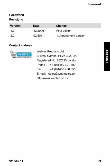
ContactaddressD
esig
ned
and
prod
uced
by
Web
tec
Gra
phic
s - E
ntw
icke
lt un
d he
rges
tellt
von
Web
tec
Gra
phic
sC
onçu
et p
rodu
it pa
r Web
tec
Gra
phic
s - D
iseña
do y
pro
duci
do p
or W
ebte
c G
raph
ics
HPM
540-
MA
-MU
L-209
9.pd
fFT
1009
2Is
sus:
A04
/08
Webtec Products Limited - reserve the right to make improvements and changes to the specification without notice.Webtec Products Limited - behält sich das Recht vor, Verbesserungen oder Änderungen der Spezifikationen ohne Ankündigung vorzunehmen.
Webtec Products Limited - se réserve le droit d'améliorer et de changer ses spécifications sans préavis.Webtec Products Limited - se reserva el derecho de realizar mejoras y cambios a las especificaciones sin previo aviso.
For Sales & Service contactAuskunft & Beratung
Contact Service commercial & maintenancePara más información sobre ventas y servicios contactar con
Distributor - Vertriebspartner - Distributeur - Distribuidor
Webtec Products Limited
Nuffield Road, St. Ives, Cambridgeshire, PE27 3LZ, UK.Tel: +44 (0) 1480 397 400 - Fax: +44 (0) 1480 466 555
e-mail: [email protected] - www.webtec.co.uk
Webster Instruments1290 E Waterford Avenue, Milwaukee, WI 53235, USA.
Tel: +1 414-769 6400 - Fax: +1 414-769 6591e-mail: [email protected] - www.webster-inst.com
Webster MesstechnikAn der Palmweide 55, 44227, Dortmund, Germany.
Tel: +49 (0) 231-9759-747 - Fax: +49 (0) 231-9759-710e-mail: [email protected] - www.webtec.co.uk
Webtec120 Avenue de Dunkerque, 59400 CAMBRAI, France.
Tel: +33 (0) 3 27 82 94 56 - Fax: +33 (0) 3 27 82 94 55e-mail: [email protected] - www.webtec.fr
Webtec Products Shanghai Representative OfficeMobile: 0086-13482546886
e-mail: [email protected] - www.webtec.com.cn
Certificate No.8242
Webtec Products LtdSt Ives, Cambs, PE27 3LZ, UKRegistered No. 832125 LondonPhone +44 (0)1480 397 400Fax +44 (0)1480 466 555E-mail: [email protected]://www.webtec.co.uk

70 V2.0/02.11
Foreword

71V2.0/02.11
Contents
ENGLISH
Contents
Foreword 69Revisions 69
1. Notesonsafety/productselection 731.1 Approved use 731.2 Skilled personnel 731.3 Accuracy of the technical documentation 731.4 High-pressure applications 731.5 Service/repair 741.6 Notes on disposal 74
2. Deviceversion/rangeofsupply 76
3. Initialuse 773.1 Charging the batteries/battery status indicator 773.2 Replacing the batteries 77
4. Keysandfunctions 784.1 Symbols and using the menus 80
5. Connectingthesensors/displayfunctions 825.1 Display format (DISP) 835.2 Display configuration (LINE) 845.3 Zero point calibration (ZERO) 855.4 Deleting MIN/MAX values (RESET) 865.5 Differential value display 865.6 Differential value alignment (IN1=IN2) 875.7 Connecting auxiliary sensors (SET AUX. SENSOR) 895.8 Error messages/warnings 92
72 V2.0/02.11
Contents
6. Devicesettings(SET) 946.1 Setting the units (SET-UNIT) 966.2 Auto power off (SET-AUTO POWER) 966.3 Setting auxiliary sensors (SET-AUX. SENSOR) 966.4 Displaying defined measurement tasks
(SET-PROJECT) 976.5 Setting the contrast (SET-CONTRAST) 986.6 Setting the time/date (SET-TIME/DATE) 986.7 Displaying the device version (SET-VERSION) 986.8 Factory setting (USER RESET) 99
7. Configuringthemeasuredvaluememory(MEMORYSET) 1007.1 Deleting measured value memory
(MEM-DELETE MEMORY) 1027.2 Setting the data format (MEM-DATA FORMAT) 1027.3 Setting the recording format (MEM-REC-CONFIG) 103
8. TheRECmenu 104
9. Recordingmeasuredvalues 1069.1 Settings for recording measured values (REC) 1069.2 The REC NAMES setting 107
10. SettingandoperatingviaPC 12010.1 Connecting to a PC 12010.2 Operating/configuring via PC 121
11. Accessories 122
12. Technicaldata 125
13. Descriptionofthememoryfunctions 127

73V2.0/02.11
Notesonsafety/productselection
ENGLISH
1. Notesonsafety/productselection1.1 ApproveduseThe device is approved for use in applications described in the Operat-ing Instructions only. Any other use is not approved and can lead to accidents or the destruction of the device. Non-approved use will result in the immediate expiry of all guarantee and warranty claims against the manufacturer.
Serious malfunctions leading to personal injury or damage to property can result from using the chosen product in applications that do not comply with the given specifications or from disre-garding the operating instructions and warning notes.
1.2 SkilledpersonnelThese operating instructions have been written for skilled personnel who are familiar with the valid regulations and standards applicable to the field of application.
1.3 AccuracyofthetechnicaldocumentationThese operating instructions were created with the utmost care and at-tention. However, we offer no guarantee that the data, graphics and drawings are correct or complete. Subject to alteration without notice.
1.4 High-pressureapplications
Selection When selecting pressure components, ensure that the overload
pressure will not be exceeded.
It is possible that the pressure cell can be deformed when the overload pressure is exceeded (depending on the duration/fre-quency and level of the pressure spike).
The 'diesel effect’ caused by entrapped air can result in pres-sure spikes that far exceed the overload pressure. The nominal pressure of the pressure component should be higher than the nominal pressure of the system to be measured.

74 V2.0/02.11
Notesonsafety/productselection
MountingPlease abide by the instructions and observe the correct tight-ening torques for the fittings or adapters being utilised.
Connector thread: ½" BSP = 90 Nm ¼" BSP = 30 Nm
1.5 Service/repairFor repairs to or calibration of the measurement instruments, please contact a Webtec sales branch.
1.6 NotesondisposalRecyclingincompliancewithWEEEPurchasing our product gives you the opportunity to return the device to Webtec at the end of its life cycle.
The EU Directive 2002/96 EC (WEEE) regulates the return and recycling of waste electrical and electronics equipment. As of 13/8/2005 manufacturers of electrical and electronics equipment in the B2B (business-to-business) category are
obliged to take back and recycle WEEE free of charge sold after this date. After that date, electrical equipment must not be disposed of through the 'normal' waste disposal channels. Electrical equipment must be disposed of and recycled separately. All devices that fall under the directive must feature this logo:
Canwebeofassistance?Webtec offers you the option of returning your old device to us at no ex-tra charge. Webtec will then professionally recycle and dispose of your device in accordance with the applicable law.

75V2.0/02.11
Notesonsafety/productselection
ENGLISH
Whatdoyouhavetodo?Once your device has reached the end of its service life, simply return it by parcel service (in the box) to your Webtec sales branch responsible for customer care - we will then initiate the necessary recycling and dis-posal measures. You will incur no costs or suffer any inconvenience.
Anyquestions?If you have any questions, please contact us or visit our website: www.webtec.co.uk

76 V2.0/02.11
Deviceversion/rangeofsupply
2. Deviceversion/rangeofsupplyThe measuring instrument and sensors enable the user to measure all relevant parameters in a hydraulic system.
Parameters:
• [bar/psi] Pressure, Dp (load sensing pumps)
• [°C/°F] Temperature
• [L/min/G/min] (U.S) volumetric flow rate
• [1/min] RPM
Automatic sensor recognition means the measuring instrument is simple to operate. It is not necessary to carry out any further settings to the device.
Plug & Work is one of the more important attributes of the device. It al-lows the measuring instrument to be ready to operate in an instance, and excludes erroneous measurements.

77V2.0/02.11
Initialuse
ENGLISH
3. InitialuseThe measuring instrument is supplied with rechargeable batteries fitted at the factory.
Charge the rechargeable batteries for at least 3 hours before using for the first time. The device is then ready for use.
3.1 Chargingthebatteries/batterystatusindicatorIf the battery power is too low, the battery symbol flashes and the meas-uring instrument turns off automatically.
Battery symbol
The measuring instrument is powered using the external power supply unit or via the car adapter. The battery can be recharged directly. The recharging process begins as soon as the power supply unit is con-nected.
► Please refer to the chapter 'Accessories' for more information about the external power supply unit and the car adapter.
3.2 Replacingthebatteries
Replacing the batteries

78 V2.0/02.11
Keysandfunctions
4. Keysandfunctions
E
A
D
C
B
B
A 11-30VDCpower supply unit 110/220 VAC-15 VDC Car adapter 12/24 VDC
B I1..I4Sensor ports
C PC(USB)D DisplayE Keypad

79V2.0/02.11
Keysandfunctions
ENGLISH
Functionkeys
ON/OFF
Confirms function/value
Selects function/value
STOP/ESC
Menukeys* These menu keys are assigned dual functions: Assignment 1. Menu level = 1 x press Assignment 2. Menu level (black background) = 1 x hold key pressed down (2 s)
ZERO Zero point calibrationIN1=IN2 Differential value alignment
*
MEM Memory configurationSET Main menu (device settings)
*
DISP MIN-MAX/ACTUAL or FS displayLINE Display configuration
*
REC Record measured values
Delete MIN/MAX values

80 V2.0/02.11
Keysandfunctions
4.1 Symbolsandusingthemenus
If the the sign '>' is displayed at the end of a menu function, press the OK key to enter an associated submenu. If the sign ':' is displayed, press the OK key to confirm the respec-tive entry.
Menusymbols
Key Function Example
>
Call up a submenu/setting
:
Confirm
s t
Select
Key assignments and symbols associated with the menu func-tions are consistent throughout this device; therefore, there will be no further explicit explanation given.
WhatthefunctionkeysdowithinthemenusUse the arrow keys to scroll between functions when several functions are available for selection in a window or a menu. The arrow keys move the cursor in the direction in which the arrow is pointing.
Press the OK key each time you wish select a function or submenu; when making alterations or adding values you must press OK to confirm your action. The OK key is used to save all settings. Press the STOP/ESC key if you wish to leave a menu or do not wish to save an entry. Key assignment and mode of operation of these three keys is always the same no matter in which menu they are used.
81V2.0/02.11
Keysandfunctions
ENGLISH
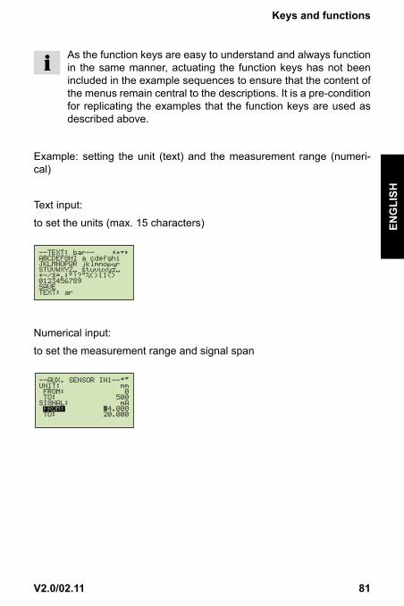
As the function keys are easy to understand and always function in the same manner, actuating the function keys has not been included in the example sequences to ensure that the content of the menus remain central to the descriptions. It is a pre-condition for replicating the examples that the function keys are used as described above.
Example: setting the unit (text) and the measurement range (numeri-cal)
Text input:
to set the units (max. 15 characters)
Numerical input:
to set the measurement range and signal span

82 V2.0/02.11
Connectingthesensors/displayfunctions
5. Connectingthesensors/displayfunctions
To avoid electrical interference, please observe the following steps:
1 Connect the sensor to the measuring instrument using the connec-tion cable.
2 Turn on the measuring instrument.
Measuring instrument with two pressure sensors
• Once turned on, all measured values are visible in the display.
• Automatic sensor recognition ensures that the measured value is indicated in the correct unit.
• No further settings to the device are required.

83V2.0/02.11
Connectingthesensors/displayfunctions
ENGLISH
• The following message will be displayed if no sensor is connected to the device:
5.1 Displayformat(DISP)
Press DISP (once)
It is possible to change the display format by pressing DISP (once only).
Available for selection:
ACT = Actual valuesMIN = Minimum valuesMAX = Maximum values (pressure spikes)FS = Full scale (upper range value)TEMP = Temperature display
The TEMPdisplay applies only to 'SCPT' type sensors.

84 V2.0/02.11
Connectingthesensors/displayfunctions
5.2 Displayconfiguration(LINE)
Press and hold LINE (2 s)
Line:1: No setting possible cannot be selected
2: Available for selection: Difference (IN1 - IN2) Addition (IN1 + IN2)
3: Volume VOL= Q3 x time
4: Available for selection: Power PWR1 = p1 x Q3 PWR2 = (p1-p2) x Q3

85V2.0/02.11
Connectingthesensors/displayfunctions
ENGLISH
5.3 Zeropointcalibration(ZERO)
If the alignment values are within the permissi-ble tolerance (2 % of FS), the values are set to zero.
If the alignment values exceed the permissible tolerance (2 % of FS), the following is dis-played: ZERO OFL.
Press ZERO (once)

86 V2.0/02.11
Connectingthesensors/displayfunctions
5.4 DeletingMIN/MAXvalues(RESET)
The MAX values measured until now are displayed in the MAX display.
Deleting MIN/MAX values.
The updated MAX values are displayed in the MAX display.Example: Loss of pressure in the hydraulic system
5.5 Differentialvaluedisplay
► The settings IN1 – IN2 are described in the chapter 'Display configu-ration (LINE)'.

87V2.0/02.11
Connectingthesensors/displayfunctions
ENGLISH
5.6 Differentialvaluealignment(IN1=IN2)
Press and holdIN1=IN2(2 s)
Carry out differential value alignments at below operating pres-sure. Connect two pressure sensors to the same connection (T-adapter). ∆p-calibration sets the tolerance of the sensors in relation to one another to zero.
This setting remains stored; it is valid only for the respective op-erating pressure.

88 V2.0/02.11
Connectingthesensors/displayfunctions
ThreeerrormessagesarepossibleforIN1=IN2:1 Alignmentvaluesexceedthepermissibletolerance:
- For sensors with automatic sensor recognition, 5 % of the upper range value (FS)
- For auxiliary sensors, 10 % of the upper range value (FS)
2 IN1-IN2isnotconfigured(DISP-LINE):
3 Measuredvariablesarenotthesame(IN1=bar/IN2=L/min)

89V2.0/02.11
Connectingthesensors/displayfunctions
ENGLISH
5.7 Connectingauxiliarysensors(SETAUX.SENSOR)
Press and hold SET (2 s)
Ensure that the electrical specifications of the auxiliary sensors are compatible with the measuring instrument/adapter. Please ensure correct PIN assignment and supply voltage and avoid short-circuits!

90 V2.0/02.11
Connectingthesensors/displayfunctions
TextinputforUNIT/SIGNALTo set the units: Text input up to max. 15 characters.
NumericalinputforFROM/TOTo set the measurement range and signal span 3-digit prefix, decimal point, 3-digit suffix.
3-digit suffix
Decimal point
3-digit prefix

91V2.0/02.11
Connectingthesensors/displayfunctions
ENGLISH
Connecting auxiliary sensors:
Measuring instrument with connector adapter and sensors for distance (mm) and force (kN).

92 V2.0/02.11
Connectingthesensors/displayfunctions
5.8 Errormessages/warnings
Display Description Whatactiontotake?
No sensor is con-nected
Turn off the measuring instrumentConnect sensor Turn on the measuring instrument
% An auxiliary sensor is connected.
Carry out settings in the menu SET- AUX.SENSOR
Sensor recognition in-terrupted (cable break or input defect)
Send measuring instrument, sensor and connection cable to Webtec.
Measurement range overflowThe measured pres-sure is outside of the measurement range
Release pressure from the systemUse sensor with wider measure-ment range
Overflow ZEROThe zero point offset value exceeds the tolerance
Check only when no pressure is applied
Overflow IN1 = IN2 Differential value alignmentThe alignment value exceeds the tolerance
Test system pressureUse sensors with wider measure-ment range
DISP LINE IN1 = IN2Wrong setting
Configure IN1-IN2
Overflow IN1 - IN2: Differential value alignment
Measured variables (sensors) must be the same IN1 / IN2 = bar IN1 / IN2 = L/min IN1 / IN2 = °C
Measured value memory full
Download measured values to PC Delete measured value memory

93V2.0/02.11
Connectingthesensors/displayfunctions
ENGLISH
Display Description Whatactiontotake?
Do not use in FAST MODE
Setting REC: START-STOP/POINT FAST MODE only for AUTO TRIGGER MANUAL possible
Recording time con-flict (DURATION)FAST MODE (0.5 ms)
REC setting
AUTO TRIGGERMANUAL Alter recording time DURA-TION
Recording time con-flict (REC RATE)
Setting MEM-SETREC CONFIG REC RATEAlter recording interval REC RATE. Press OK to confirm

94 V2.0/02.11
Devicesettings(SET)
6. Devicesettings(SET)
Press and hold SET (2 s)

95V2.0/02.11
Devicesettings(SET)
ENGLISH
96 V2.0/02.11
Devicesettings(SET)
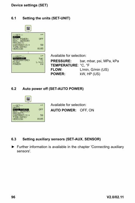
6.1 Settingtheunits(SET-UNIT)
MEM
Available for selection:PRESSURE: bar, mbar, psi, MPa, kPaTEMPERATURE: °C, °FFLOW: L/min, G/min (US)POWER: kW, HP (US)
6.2 Autopoweroff(SET-AUTOPOWER)
Available for selection:AUTOPOWER: OFF, ON
6.3 Settingauxiliarysensors(SET-AUX.SENSOR)
► Further information is available in the chapter 'Connecting auxiliary sensors'.
97V2.0/02.11
Devicesettings(SET)
ENGLISH
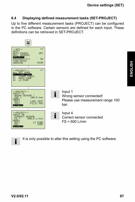
6.4 Displayingdefinedmeasurementtasks(SET-PROJECT)Up to five different measurement tasks (PROJECT) can be configured in the PC software. Certain sensors are defined for each input. These definitions can be retrieved in SET-PROJECT.
Input 1Wrong sensor connected! Please use measurement range 100 bar.
Input 4Correct sensor connected FS = 600 L/min
It is only possible to alter this setting using the PC software.

98 V2.0/02.11
Devicesettings(SET)
6.5 Settingthecontrast(SET-CONTRAST)
Available for selection:CONTRAST: 10 . . 100 %
6.6 Settingthetime/date(SET-TIME/DATE)
Available for selection:HOUR: 0 . . 23MINUTE: 0 . . 59SECOND: 0 . . 59DAY: 1 . . 31MONTH: 1 . . 12YEAR: 1 . . 99
6.7 Displayingthedeviceversion(SET-VERSION)

99V2.0/02.11
Devicesettings(SET)
ENGLISH
6.8 Factorysetting(USERRESET)Proceed as follows to restore the measuring instrument to its factory-set default settings:
1 Turn off the measuring instrument.
2 Press and hold down the MEM-SET key.
3 Press the ON/OFF key.
4 Press OK to confirm USER RESET
100 V2.0/02.11
Configuringthemeasuredvaluememory
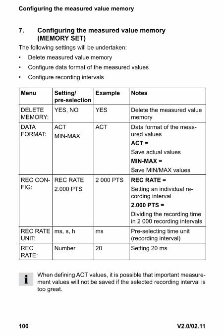
7. Configuringthemeasuredvaluememory(MEMORYSET)
The following settings will be undertaken:
• Delete measured value memory
• Configure data format of the measured values
• Configure recording intervals
Menu Setting/pre-selection
Example Notes
DELETE MEMORY:
YES, NO YES Delete the measured value memory
DATA FORMAT:
ACT MIN-MAX
ACT Data format of the meas-ured valuesACT=Save actual valuesMIN-MAX=Save MIN/MAX values
REC CON-FIG:
REC RATE2.000 PTS
2 000 PTS RECRATE=Setting an individual re-cording interval2.000PTS=Dividing the recording time in 2 000 recording intervals
REC RATE UNIT:
ms, s, h ms Pre-selecting time unit (recording interval)
REC RATE:
Number 20 Setting 20 ms
When defining ACT values, it is possible that important measure-ment values will not be saved if the selected recording interval is too great.
101V2.0/02.11
Configuringthemeasuredvaluememory
ENGLISH
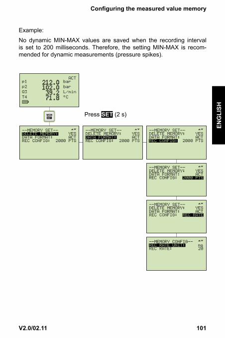
Example:
No dynamic MIN-MAX values are saved when the recording interval is set to 200 milliseconds. Therefore, the setting MIN-MAX is recom-mended for dynamic measurements (pressure spikes).
Press SET (2 s)

102 V2.0/02.11
Configuringthemeasuredvaluememory
7.1 Deletingmeasuredvaluememory(MEM-DELETEMEMORY)
press once (briefly).
Available for selection:DELETEMEMORY: YES/NO
The measured value memory will be deleted when the OK key is pressed to confirm the action.
7.2 Settingthedataformat(MEM-DATAFORMAT)
Available for selection:DATAFORMAT: ACT MIN/MAX FAST
When set to FAST, the recording interval for measuring and stor-ing at IN1 is 0.5 ms.

103V2.0/02.11
Configuringthemeasuredvaluememory
ENGLISH
7.3 Settingtherecordingformat(MEM-REC-CONFIG)
RECCONFIGTwo different formats can be set:
a.Format2.000PTSThe measurement curves are saved with a resolution of 2.000 intervals (points).
b.FormatRECRATEThe measurement curves are saved at a defined interval.
Example: 20 ms

104 V2.0/02.11
TheRECmenu
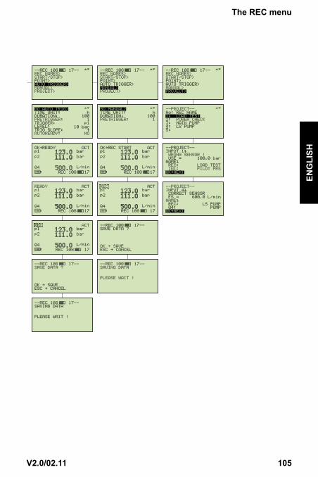
8. TheRECmenu
105V2.0/02.11
TheRECmenu
ENGLISH

106 V2.0/02.11
Recordingmeasuredvalues
9. Recordingmeasuredvalues9.1 Settingsforrecordingmeasuredvalues(REC)
The following parameters are displayed in the information bar:
Number of recorded measured values. In this example there are 108 measurements saved to memory.
Memory allocation
Number of measured values that can still be recorded. With the current setting/configuration it is possible to save a further 17 measurements.
The REC symbol flashes when measured values are being written to memory.

107V2.0/02.11
Recordingmeasuredvalues
ENGLISH
9.2 TheRECNAMESsetting
Designations (names) for measurements and channels IN1/IN2/IN3/IN4 are defined through the text/numerical input. These settings remain saved in the measuring instrument.

108 V2.0/02.11
Recordingmeasuredvalues
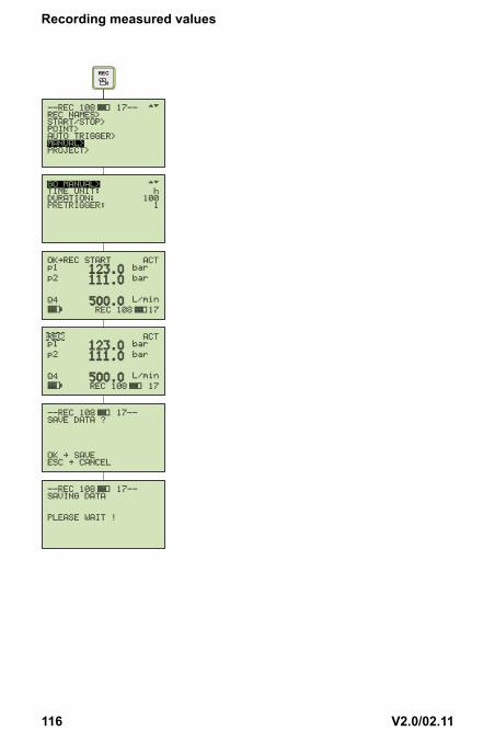
MemoryfunctionSTART/STOPThe user controls the recording of measured values using the START and STOP/ESC keys.
The data format FAST (recording interval ACT values in 0.5 ms) cannot be used when the device is in the START/STOP mode.
109V2.0/02.11
Recordingmeasuredvalues
ENGLISH
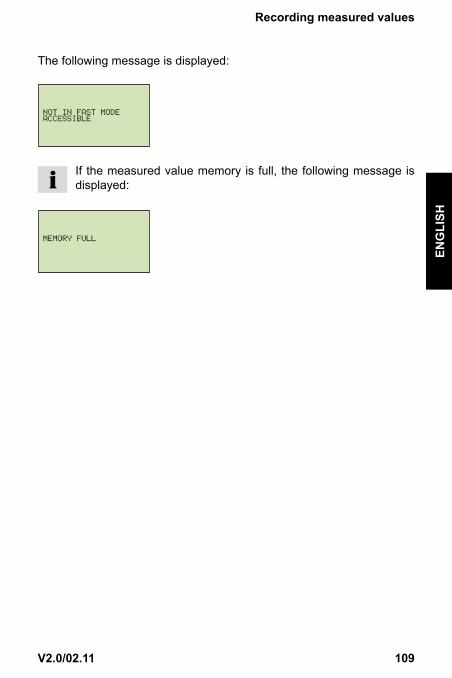
The following message is displayed:
If the measured value memory is full, the following message is displayed:

110 V2.0/02.11
Recordingmeasuredvalues
MemoryfunctionPOINTMeasurement points representing a given machine sequence (for ex-ample, lifting, sinking, operation under load, off-load operation etc.) are saved in a 'point-to-point curve'. In the example shown, the channels p1, p2 and Q4 are connected.
The first data record will be saved; for example, p1, p2 and Q4
The second data record will be saved; for example, p1, p2 and Q4
The third data record will be saved; for example, p1, p2 and Q4

111V2.0/02.11
Recordingmeasuredvalues
ENGLISH
Press the OK key to save the data records. Press the STOP/ESC key to end recording measured values; all data records will be written in the measured value memory.
The data format FAST (recording interval ACT values in 0.5 ms) cannot be used when the device is in the START/STOP mode.
The following message is displayed:
If the measured value memory is full, the following message is displayed:

112 V2.0/02.11
Recordingmeasuredvalues
MemoryfunctionAUTOTRIGGERThe function Auto Trigger documents the process of recording meas-ured values triggered by a defined start signal (for example, pressure on channel 2 → 125 bar). In response, a sequence of measured values are automatically recorded until the previously set measurement time expires.
Time-dependent functions (for example, making operations or produc-tion cycles) are measured when recording measured values.
The following parameters must be set:
Menu Setting/pre-selection
Values Notes
TIME UNIT> sec, hrs h Pre-selected time unit (trigger/pre-trigger)
DURATION> Number 100 Recording time
PRE TRIGGER>
Number 1 Pre-trigger time (time before the trigger signal)
TRIGGER> IN p1 Starting-point measuring channel
LEVEL> Number 125 bar Start point value
TRIG SLOPE>
▲ ▼ ▲ Ascending or descending edge
AUTO READY>
YES, NO YES Recording of measured values is repeated auto-matically

113V2.0/02.11
Recordingmeasuredvalues
ENGLISH

114 V2.0/02.11
Recordingmeasuredvalues
If conflicts arise between the recording time and the set recording interval, the following message is displayed:
1.FASTMODE
Configuring a longer recording interval
2.RECRATE
Configuring a longer recording interval
If the measured value memory is full, the following message is displayed:
Delete measured value memory or transfer to PC.
115V2.0/02.11
Recordingmeasuredvalues
ENGLISH
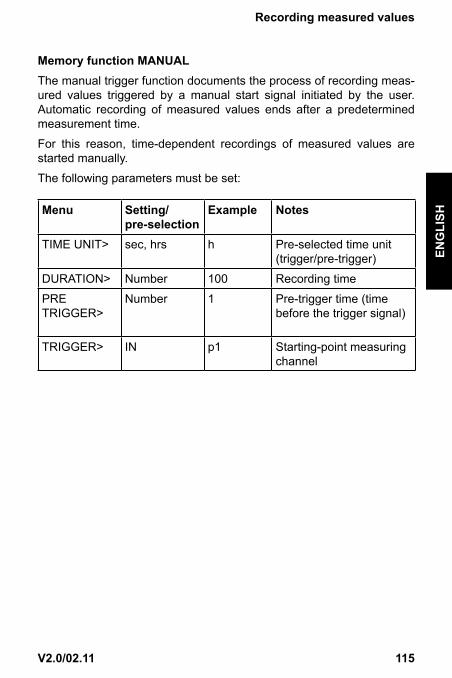
MemoryfunctionMANUALThe manual trigger function documents the process of recording meas-ured values triggered by a manual start signal initiated by the user. Automatic recording of measured values ends after a predetermined measurement time.
For this reason, time-dependent recordings of measured values are started manually.
The following parameters must be set:
Menu Setting/pre-selection
Example Notes
TIME UNIT> sec, hrs h Pre-selected time unit (trigger/pre-trigger)
DURATION> Number 100 Recording time
PRE TRIGGER>
Number 1 Pre-trigger time (time before the trigger signal)
TRIGGER> IN p1 Starting-point measuring channel
116 V2.0/02.11
Recordingmeasuredvalues

117V2.0/02.11
Recordingmeasuredvalues
ENGLISH
If conflicts arise between the recording time and the set record-ing interval, the following message is displayed.
1.FASTMODE
Configuring a longer recording interval
2.RECRATE
Configuring a longer recording interval
If the measured value memory is full, the following message is displayed:
Delete measured value memory or transfer to PC.

118 V2.0/02.11
Recordingmeasuredvalues
RecordingmeasuredvalueswithdefaultPROJECTsettingsIn this setting, measurements are made using a defined sensor configu-ration. This configuration is defined by the user using the PC software. This avoids false measurements and wrong settings.
The preset parameters are altered in the PC software and transferred to the measuring instrument.
The following parameters can be set:
Menu Setting/pre-selection
Notes
REC NAME>
No:1 . . 5
Load Test There are max. 5 prede-fined settings (tests) avail-able for selection.
INPUT> PILOT PRS Defined sensors are de-fined for each channel.
WRONG SENSOR !
USE 150 bar Warns of wrong sensor.A pressures sensor with the corresponding FS (full scale) must be connected to this channel.
CORRECT SENSOR!
FS 600 L/min Indicates correct sensor.The next channel can be connected.
When all of the sensors are connected, the respective type of record-ing (START/STOP, POINT, AUTO TRIGGER, MANUAL) is selected and performed automatically.

119V2.0/02.11
Recordingmeasuredvalues
ENGLISH

120 V2.0/02.11
SettingandoperatingviaPC
10. SettingandoperatingviaPC10.1 ConnectingtoaPC
Measuring instrument, PC and USB cable
1 Connect the measuring instrument to the PC (USB cable)
2 Launch PC software.
The following screen is displayed:
Once the procedure has been confirmed, the measuring instrument will be initialised and can communicate with the PC.

121V2.0/02.11
SettingandoperatingviaPC
ENGLISH
10.2 Operating/configuringviaPCAll further steps and settings are described in detail in the PC software.
• Online measurement
• Reading out the measured value memory
• PROJECT definition
• Administering and analysing measurement curves

122 V2.0/02.11
Accessories
11. Accessories
Turbineflowmeters
Description Modelnumber PartnumberFlow Range 1 - 15 LPM, 1/2“ BSPP ports.
CT15-SR-B-B-6 FT9500-03
Flow Range 2 - 60 LPM, 3/4“ BSPP ports.
CT60-SR-B-B-6 FT9501-03
Flow Range 5 - 150 LPM, 3/4“ BSPP ports.
CT150-SR-B-B-6 FT9502-03
Flow Range 8 - 300 LPM, 1“ BSPP ports.
CT300-SR-B-B-6 FT9503-03
Flow Range 15 - 600 LPM, 1-1/4“ BSPP ports.
CT600-SR-B-B-5 FT9718-03
Flow Range 20 - 750 LPM, 1-7/8“ UN ports.
CT750-SR-S-B-7 FT9506-03
Turbineflowmeterswithloadvalve
Description Modelnumber PartnumberFlow Range 8 - 300 LPM, 1“ BSPP ports.
CT300R-SR-B-B-6 FT9507-03
Flow Range 15 - 600 LPM, 1-7/8“ UN ports.
CT600R-SR-S-B-7 FT9509-03
Flow Range 20 - 750 LPM, 1-7/8“ UN ports.
CT750R-SR-S-B-7 FT9510-03
Pressuretransducers
Description Modelnumber PartnumberPressure sensor -1 to 15 bar (0-15 bar HPM420) c/w M16x2 test connector (built-in temp sensor for reference, only with 440/460 readouts)
SR-PTT-015-05-0C FT9783-015

123V2.0/02.11
Accessories
ENGLISH
Pressure sensor 0-60 bar c/w M16x2 test connector (built-in temp sensor for reference, only with 440/460/540 readouts)
SR-PTT-060-05-0C FT9783-060
Pressure sensor 0-150 bar c/w M16x2 test connector (built-in temp sensor for reference, only with 440/460/540 readouts)
SR-PTT-150-05-0C FT9783-150
Pressure sensor 0-400 bar c/w M16x2 test connector (built-in temp sensor for reference, only with 440/460/540 readouts)
SR-PTT-400-05-0C FT9783-400
Pressure sensor 0-600 bar c/w M16x2 test connector (built-in temp sensor for reference, only with 440/460/540 readouts)
SR-PTT-600-05-0C FT9783-600
Pressure sensor 0-1000 bar c/w M16x2 test connector (built-in temp sensor for reference, only with 440/460/540 readouts)
SR-PTT-1K0-05-0C FT9783-1K0
Temperaturetransducer
Description Modelnumber PartnumberTemperature Probe, -25 °C to +125 °C, M10 x 1 thread.
SR-TTP-400-05-0C FT9787
Speedtransducers
Description Modelnumber PartnumberTachometer Photo-head with 3 m cable
SR-RPM-300-05-3C FT9781
Contact wheel add SR-RPM-WHL-00-0C FT9282
Focus adaptor add SR-RPM-ADP-00-0C FT9283

124 V2.0/02.11
Accessories
Cablesandconnectors
Description Modelnumber PartnumberUniversal sensor cable, 3 m long, 5 pin M/M
SR-CBL-003-55-MM
FT9788
Extension cable, 5 m long, 5 pin F/M
SR-CBL-005-55-FM
FT9789
Extension / converter cable, 3 m long, 4pin F - 5pin M
SR-CBL-003-45-FM
FT9275
Cable kit for current / voltage module
SR-CBL-VAD-BP-1C
FT9786
HPM charger SR-HPM-PSU-MC-1C
FT9272
In-car charger / adaptor SR-HPM-CHG-03-0C
FT9863
4 pin F / 5 pin M adaptor for connecting 4 pin sensors to 5 pin readouts
SR-BLT-ADP-45-FM
FT9497
Converter cable, 2 m long, 4pin M - 5pin M
SR-CBL-002-54-MM
FT9821
Cable HPM540 to PC - USB SR-CAB-540-PC-USB
FT10384
GeneralAccessiores
Description Modelnumber PartnumberExternal trigger adaptor SR-EXT-TRG-05-
1CFT9782
Voltage / current module, custom sensor input
SR-VADC-1C FT10138
Case for HPM-440/460/540 and up to 3 pressure / temperature transducers and connecting cables
SR-PCC-460-##-A FT9321
125V2.0/02.11
Technicaldata
ENGLISH
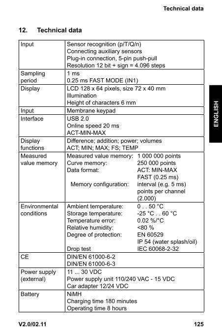
12. Technicaldata
Input Sensor recognition (p/T/Q/n) Connecting auxiliary sensors Plug-in connection, 5-pin push-pull Resolution 12 bit + sign = 4.096 steps
Sampling period
1 ms 0.25 ms FAST MODE (IN1)
Display LCD 128 x 64 pixels, size 72 x 40 mm Illumination Height of characters 6 mm
Input Membrane keypad Interface USB 2.0
Online speed 20 ms ACT-MIN-MAX
Display functions
Difference; addition; power; volumes ACT; MIN; MAX; FS; TEMP
Measured value memory
Measured value memory: 1 000 000 pointsCurve memory: 250 000 pointsData format: ACT: MIN-MAX
FAST (0.25 ms)Memory configuration: interval (e.g. 5 ms)
points per channel (2.000)
Environmental conditions
Ambient temperature: 0 . . 50 °C Storage temperature: -25 °C . . 60 °C Temperature error: 0.02 %/°C Relative humidity: <80 % Degree of protection: EN 60529 IP 54 (water splash/oil) Drop test IEC 60068-2-32
CE DIN/EN 61000-6-2 DIN/EN 61000-6-3
Power supply (external)
11 ... 30 VDC Power supply unit 110/240 VAC - 15 VDC Car adapter 12/24 VDC
Battery NiMH Charging time 180 minutes Operating time 8 hours

126 V2.0/02.11
Technicaldata
Housing Polyamide 235 x 106 x 53 mm Weight 530 g
PC software SensoWin
Read out/depict measurement data and analyse on PC Device settings read out/process Load device settings into measuring instrument from library

127V2.0/02.11
Descriptionofthememoryfunctions
ENGLISH
13. Descriptionofthememoryfunctions
ConfiguringthemeasuredvaluememoryDATA FORMAT ACT During the recording interval
(for example, 50 ms), the current meas-urement value (ACT) only will be written to the measured value memory.
MIN-MAX During the recording interval (for example, 50 ms) one MIN and one MAX value will be written to the meas-ured value memory.
REC CONFIG 2 000 PTS The selected recording time is auto-matically divided into a fixed number of recording intervals per channel.Example: 10 min recording time = 600 s Duration of recording interval = 600 s ÷ 2.000 = 300 ms
REC RATE Definition of an individual recording interval (for example, 5 ms).Based on the settings (DATA FORMAT/REC RATE), the measuring instrument examines if the selected recording time must be extended.Example: Recording time 100 h/conflict recording time
FAST MODE ACT measured values only are saved at a fixed recording interval of 0.5 ms via IN1. All other inputs (INx) are not in function.

128 V2.0/02.11
Descriptionofthememoryfunctions
Selectingthememoryfunction:SCPTpressure/temperaturesensorRecordingtime60sMemoryfunction
SettingDATAFORMAT
SettingRECCONFIG
Curvememory(points)
Numberofmeasuredvalues/pointsp(bar)T(°C)
START/STOP
ACTMIN-MAX
– 120.000 p (bar) = 15.000T (°C) = 15.000
AUTO/MANUAL TRIGGER
ACTMIN-MAX
2.000 PTS 250.000 p (bar) = 2.000T (°C) = 60
REC RATE (5 ms)
250.000 p (bar) = 12.000T (°C) = 60

129V2.0/02.11
Descriptionofthememoryfunctions
ENGLISH
ImportantinformationabouttheSTART/STOPmode:START/STOP The settings made under REC CONFIG are not
relevant in this mode. The recording time is still unknown when the process of recording meas-ured values begins. For this reason, the recording interval is dynamically optimised and appropriately adapted as the measured values are being record-ed. The curve memory can store approx. 120.000 measured values.When SCPT sensors are connected, the meas-urement values for temperature and pressure are saved at the same recording interval.

130 V2.0/02.11
Descriptionofthememoryfunctions
1.Determiningthenumberofrecordingintervals:Channels Measured
variableNumber
ofmeasuredvalues
Numberofrecordingintervals
120.000 ÷ measurement values = number of recording intervals
Example ➀
4 (SCPT) °Cbar
Measured values
448 120.000 ÷ 8 = 15.000
Example ➁
2 (SCPT)
1 (SCFT)1 (SCRPM)
°Cbar
L/minRPM
Measured values
22116 120.000 ÷ 6 = 20.000

131V2.0/02.11
Descriptionofthememoryfunctions
ENGLISH
2.Determiningthedurationoftherecordinginterval:Time Channels Number
ofmeasuredvalues
Durationofrecordinginterval
Example ➀
60 s 60.000 ms
4 (SCPT) 8 60.000 ÷ 15.000 = 4 ms
30 s 30.000 ms
4 (SCPT) 8 30.000 ÷ 15.000 = 2 ms
Example ➁
60 s 60.000 ms
2 (SCPT) 1 (SCFT) 1 (SCRPM)
6 60.000 ÷ 20.000 = 3 ms
40 s 40.000 ms
2 (SCPT) 1 (SCFT) 1 (SCRPM)
6 40.000 ÷ 20.000 = 2 ms

132 V2.0/02.11
Descriptionofthememoryfunctions
ImportantinformationabouttheAUTO/MANUALTRIGGERmodesAUTO/MANUAL TRIGGER
The settings made under REC CONFIG are rel-evant in this mode. The recording time is known when the process of recording measured values begins.The curve memory can store 250.000 measured values.
REC CONFIG 2 000 PTS
DURATION ÷ 2.000 = duration of the recording interval/channelWhen SCPT sensors are connected, the meas-ured temperature values are saved at a recording interval of 1 second.
REC CONFIG REC RATE
Measured values are recorded at the set interval (REC RATE).When SCPT sensors are connected, the meas-ured temperature values are saved at a recording interval of 1 second.

133V2.0/02.11
Descriptionofthememoryfunctions
ENGLISH
1.DeterminingthedurationoftherecordingintervalforRECCONFIG2000PTS:Time Channels Meas-
uredvariable
Numberofmeas-urementvalues
Durationoftherecordinginterval
60 s60.000 ms
4 (SCPT) °Cbar
4 x 604 x 2.000
60.000 ÷ 2.000 = 30 ms
Stored measurement points 8.240
30 s30.000 ms
4 (SCPT) °Cbar
4 x 304 x 2.000
30.000 ÷ 2.000 = 15 ms
Stored measurement points 8.120
60 s60.000 ms
2 (SCPT)
1 (SCFT)1 (SCRPM)
°CbarL/minRPM
2 x 602 x 2.0001 x 2.0001 x 2.000
60.000 ÷ 2.000 = 30 ms
Stored measurement points 8.120
40 s40.000 ms
2 (SCPT)
1 (SCFT)1 (SCRPM)
°CbarL/minRPM
2 x 402 x 2.0001 x 2.0001 x 2.000
40.000 ÷ 2.000 = 20 ms
Stored measurement points 8.080

134 V2.0/02.11
Descriptionofthememoryfunctions
2.DeterminingthenumberofrecordingintervalsforRECCONFIG/RECRATE5ms:Time Channels Meas-
uredvariable
Numberofmeas-uredvalues
Numberofre-cordingintervals
60 s60.000 ms
4 (SCPT) °Cbar
4 x 604 x 12.000
60.000 ÷ 5 = 12.000
Stored measurement points 48.240
30 s30.000 ms
4 (SCPT) °Cbar
4 x 304 x 6.000
30.000 ÷ 5 = 6.000
Stored measurement points 24.120
60 s60.000 ms
2 (SCPT)
1 (SCFT)1 (SCRPM)
°CbarL/minRPM
2 x 602 x 12.0001 x 12.0001 x 12.000
60.000 ÷ 5 = 12.000
Stored measurement points 48.120
40 s40.000 ms
2 (SCPT)
1 (SCFT)1 (SCRPM)
°CbarL/minRPM
2 x 402 x 8.0001 x 8.0001 x 8.000
40.000 ÷ 5 = 8.000
Stored measurement points 32.080