foreword - tanga moteursservice.tanga-moteurs.ro/data/yamaha sr 125 '99 - service manual... ·...
TRANSCRIPT

FOREWORD
This Supplementary Service Manual has been prepared to introduce new service and data for theSR125 ’99. For complete service information procedures it is necessary to use this SupplementaryService Manual together with the following manual.
SR125 SERVICE MANUAL: 3MW-AE1SR125 SUPPLEMENTARY SERVICE MANUAL: 3MW-AE2
SR125 ’99SUPPLEMENTARYSERVICE MANUAL
1998 by Yamaha Motor Co., Ltd.First Edition, October 1998
Any reproduction or unauthorized usewithout the written permission of
Yamaha Motor Co., Ltd. is expresslyprohibited.
NOTE:
CAUTION:
EB001000
NOTICEThis manual was produced by the Yamaha Motor Company primarily for use by Yamaha dealers andtheir qualified mechanics. It is not possible to include all the knowledge of a mechanic in one manual,so it is assumed that anyone who uses this book to perform maintenance and repairs on Yamaha mo-torcycles has a basic understanding of the mechanical ideas and the procedures of motorcycle repair.Repairs attempted by anyone without this knowledge are likely to render the motorcycle unsafe andunfit for use.
Yamaha Motor Company, Ltd. is continually striving to improve all its models. Modifications and signifi-cant changes in specifications or procedures will be forwarded to all authorized Yamaha dealers andwill appear in future editions of this manual where applicable.
Designs and specifications are subject to change without notice.
IMPORTANT INFORMATIONParticularly important information is distinguished in this manual by the following notations.
The Safety Alert Symbol means ATTENTION! BECOME ALERT! YOURSAFETY IS INVOLVED!
Failure to follow WARNING instructions could result in severe injury or death tothe scooter operator, a bystander or a person inspecting or repairing the scoot-er.
A CAUTION indicates special precautions that must be taken to avoid damageto the scooter.
NOTE: A NOTE provides key information to make procedures easier or clearer.

12
6
7
6
4 3
8
YP002000
HOW TO USE THIS MANUAL
MANUAL ORGANIZATIONThis manual consists of chapters for the main categories of subjects. (See “Illustrated symbols”)
1st title 1 : This is the title of the chapter with its symbol on the upper right corner of each page.
2nd title 2 : This title indicates the section of the chapter and only appears on the first page of eachsection. It is located in the upper left corner of the page.
3rd title 3 : This title indicates a sub-section that is followed by step-by-step procedures accompa-nied by corresponding illustrations.
EXPLODED DIAGRAMSTo heps identify parts and clarify procedure steps, there are exploded diagrams at start of each remov-al and disassembly section.1. An easy-to-see exploded diagram 4 is provided for disassembly and assembly jobs.2. Numbers 5 are given in the order of jobs in the exploded diagram. A number that is enclosed by a
circle indicates a disassembly step.3. An explanation of jobs and notes is presented in an easy-to-read way by the use of symbol marks
6 . The meanings of the symbol marks are given on the next page.4. A job instruction chart 7 accompanies the exploded diagram, providing the order of jobs, names of
parts, notes in jobs, etc.5. For jobs requiring more information, the step-by-step format supplements 8 are given in addition to
the exploded diagram and the job instruction chart.

22
1
3
5
7
9
2
4
8
6
24 25
2321
19 2018
16 1715
1413
11 12
10
GENINFO SPEC
ENG
CARB
ELECCHAS
COOL
INSPADJ
TRBLSHTG
EB003000
ILLUSTRATED SYMBOLSIllustrated symbols 1 to 9 are designed asthumb tabs to indicate the chapter’s numberand content.
1 General information
2 Specifications
3 Periodic inspection and adjustment
4 Engine
5 Cooling system
6 Carburetion
7 Chassis
8 Electrical
9 Troubleshooting
Illustrated symbols 10 to 17 are used to identify thespecifications appearing in the text.
10 Possible to maintain with engine mounted
11 Filling fluid
12 Lubricant
13 Special tool
14 Tightening
15 Wear limit, clearance
16 Engine speed
17 Ω, V, A
Illustrated symbols 18 to 23 in the exploded dia-grams indicate the types of lubricants and lu-brication points.18 Apply engine oil
19 Apply gear oil
20 Apply molybdenum disulfide oil
21 Apply wheel bearing grease
22 Apply lightweight lithium-soap base grease
23 Apply molybdenum disulfide grease
Illustrated symbols 24 to 25 in the exploded dia-grams indicate the where to apply locking agent24 and when to install new parts 25 .24 Apply locking agent (LOCTITE )
25 Use new one

CONTENTS
GENERAL SPECIFICATIONSGENERAL SPECIFICATIONS 1. . . . . . . . . . . . . . . . . . . . . . . . . . . . . . . . MAINTENANCE SPECIFICATIONS 2. . . . . . . . . . . . . . . . . . . . . . . . . . .
ENGINE 2. . . . . . . . . . . . . . . . . . . . . . . . . . . . . . . . . . . . . . . . . . . . . . . . CHASSIS 2. . . . . . . . . . . . . . . . . . . . . . . . . . . . . . . . . . . . . . . . . . . . . . . . . ELECTRICAL 2. . . . . . . . . . . . . . . . . . . . . . . . . . . . . . . . . . . . . . . . . . . . .
TIGHTENING TORQUES 3. . . . . . . . . . . . . . . . . . . . . . . . . . . . . . . . . . . . . . ENGINE 3. . . . . . . . . . . . . . . . . . . . . . . . . . . . . . . . . . . . . . . . . . . . . . . . . . CHASSIS 3. . . . . . . . . . . . . . . . . . . . . . . . . . . . . . . . . . . . . . . . . . . . . . . . .
CABLE ROUTING 4. . . . . . . . . . . . . . . . . . . . . . . . . . . . . . . . . . . . . . . . . . . . .
PERIODIC INSPECTIONS AND ADJUSTMENTSCHECKING AND ADJUSTING THE STEERING HEAD 9. . . . . . . . . . . . .
CHECKING AND ADJUSTING THE STEERING HEAD 9. . . . . . . . .
ENGINE OVERHAULCYLINDER HEAD 11. . . . . . . . . . . . . . . . . . . . . . . . . . . . . . . . . . . . . . . . . . . . .
CYLINDER HEAD 11. . . . . . . . . . . . . . . . . . . . . . . . . . . . . . . . . . . . . . . . . . CHECKING THE TIMING CHAIN TENSIONER 12. . . . . . . . . . . . . . . . CYLINDER HEAD INSTALLATION 12. . . . . . . . . . . . . . . . . . . . . . . . . . .
CHASSISSTEERING 15. . . . . . . . . . . . . . . . . . . . . . . . . . . . . . . . . . . . . . . . . . . . . . . . . . . UNDER BRACKET 15. . . . . . . . . . . . . . . . . . . . . . . . . . . . . . . . . . . . . . . . . .
’99 SR125 WIRING DIAGRAM


–1–
GENERAL SPECIFICATIONS SPEC
SPECIFICATIONSGENERAL SPECIFICATIONS
Model SR125
Model code: 3MW8
Dimensions:Overall height 1,100 mm
Chassis:Caster angleTrail
26.7590 mm
Wheel travel:Rear wheel travel 76 mm
Bulb wattage quantity:HeadlightAuxiliary lightTail /brake lightFlasher lightMeter lightHigh beam indicatorNeutral indicatorTurn indicator
12 V 60 W/55 W 112 V 4 W 112 V 5 W/21 W 112 V 21 W 414 V 3 W 112 V 1.7 W 112 V 1.7 W 112 V 1.7 W 1

–2–
MAINTENANCE SPECIFICATIONS SPEC
MAINTENANCE SPECIFICATIONSENGINE
Item Standard Limit
Cam chain:Cam chain type/No. of linksCam chain adjustment
DID 25SH/104 ENDLESSAutomatic
Carburetor:Engine idle speed 1,300 – 1,400 rpm
CHASSIS
Item Standard Limit
Steering system: Steering bearing type Angular bearing
Front suspension: Fork spring free length Fitting length Oil capacity Oil level Oil grade
353.4 mm338.4 mm0.187 L (187 cm3)138 mmFork oil 10 W or equivalent
321 mm
ELECTRICAL
Item Standard Limit
Ignition coil:Primary winding resistanceSecondary winding resistance
0.184 – 0.276 Ω at 20C6.32 – 9.48 kΩ at 20C
Flasher relay:TypeModel/manufacturerFlasher frequency
Full transistor typeFE246BH/DENSO75 – 95 cycle/min

–3–
MAINTENANCE SPECIFICATIONS SPEC
NOTE:
TIGHTENING TORQUESENGINE
Part to be tightened Part name Threadsize
Q’tyTightening
torque Remarksgsize
yNm mkg
Timing chain tensioner boltTiming drain tensioner cap bolt
BoltBolt
21
1010
0.10.1
CHASSIS
Part to be tightened Thread sizeTightening
torque RemarksgNm mkg
Handle crown and front forkHandle crown and steering shaftHandlebar holder (under and upper)Steering ring nut
M8M22M8
M25
19110204
1.911.02.00.4 Refer to NOTE
1. First, tighten the ring nut to approximately 38 Nm (3.8mkg)with a torque wrench, then loosen thering nut completely.
2. Retighten the ring nut to specification.

–4–
CABLE ROUTING SPEC
12 Wireharness13 Horn lead14 Headlight earth lead15 Auxilialy light lead16 Meter lead
A Faster the handlebar switch lead(left and right) front brake switch lead clutch switch lead to the handlebar with a band.
B Don’t contact the horn and wire-harness.
C To auxiliary light.D To headlight.
CABLE ROUTING1 Speed meter cable2 Handlebar switch lead (left)3 Main switch lead4 Front brake switch lead5 Throttle cable6 Brake hose7 Handlebar switch lead (right)8 Clutch cable9 Clutch switch lead10 Right flasher lead11 Left flasher lead

–5–
CABLE ROUTING SPEC
13 Clutch cable guide14 Right handlebar switch lead15 Front brake switch lead16 Clutch switch lead17 Clutch cable18 Rear stop switch19 Sidestand relay20 Battery breather hose
A Align the clamp to the white tape on the wireharness.
B Route the brake hose through the brake hose holder.
C Route the clutch cable through the clutch cable guide.
D Route the throttle cable, front brake switch lead handlebar switch lead through the guide.
1 Flasher relay2 Clamp3 Wireharness4 High tension cord5 Collar6 Ignition coil7 Earth lead8 Ignition coil lead9 Throttle cable10 Brake hose11 Brake hose holder12 Wire guide

–6–
CABLE ROUTING SPEC
E Clamp the clutch cable to thedown tube of the frame.
F Cover the sack to the couplers.

–7–
1 Pick up coil lead2 Neutral switch lead3 C.D.I unit4 Rear flasher lead (right)5 Rear flasher lead (left)6 Tail /Brake light lead7 Clutch switch lead8 Wireharness9 Clamp10 Throttle cable11 Thermo switch lead12 Thermo switch
A Fasten the junction to the wire-harness with a band and cut the end of band. (except for ignition coil lead and earth lead.)
B Clamp the sidestand switch lead, battery negative lead and cut the end.
C Route the battery positive lead between air filter case and mud guard set the battery positive ter-minal.
CABLE ROUTING SPEC
13 Battery negative lead14 Starter motor lead15 Rectifier /Regulator16 Starter relay17 Battery positive lead18 Side stand switch lead19 Side stand switch20 Clutch cable21 Wire guide22 Brake hose23 Brake hose holder24 Wire holder25 Speed meter cable26 Handlebar switch lead

–8–
H Route the brake hose through the brake hose holder.
I Clamp the speed meter cable to the under bracket and through the wire holder of front fender.
CABLE ROUTING SPEC
D Route the leads inside the frame bracket.
E Clamp the starter relay lead rec-tifier / regulator lead and side-stand switch lead.
F Clamp the rectifier / regulator lead.
G Fasten the leads witin 40 m from rectifire/regulator with a band.
–9–
CHECKING AND ADJUSTING THE STEERING HEADINSPADJ
WARNING
NOTE:
EB304130
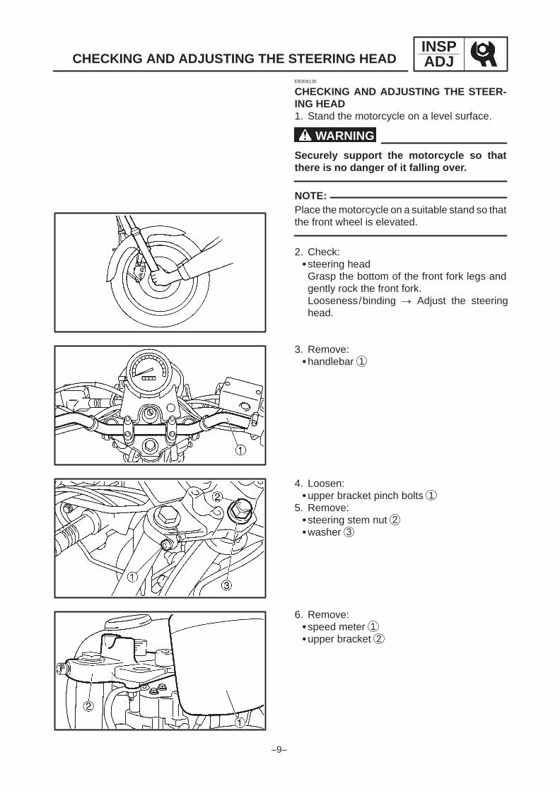
CHECKING AND ADJUSTING THE STEER-ING HEAD1. Stand the motorcycle on a level surface.
Securely support the motorcycle so thatthere is no danger of it falling over.
Place the motorcycle on a suitable stand so thatthe front wheel is elevated.
2. Check:steering headGrasp the bottom of the front fork legs andgently rock the front fork.Looseness/binding Adjust the steeringhead.
3. Remove:handlebar 1
4. Loosen:upper bracket pinch bolts 1
5. Remove:steering stem nut 2washer 3
6. Remove:speed meter 1upper bracket 2

–10–
CHECKING AND ADJUSTING THE STEERING HEADINSPADJ
NOTE:
WARNING
NOTE:
110 Nm (11.0 mkg)
26 Nm (2.6 mkg)
6.Adjust:steering head
a. Remove the lock washer 1 , the upper ringnut 2 , and the rubber washer 3 .
b. Loosen the lower ring nut 4 and then tightenit to specification with a ring nut wrench 5 .
Set the torque wrench at a right angle to thesteering nut wrench.
Steering nut wrench90890-01268
Lower ring nut (initial tightening torque)
38 Nm (3.8 mkg)
c. Loosen the lower ring nut completely, thentighten it to specification.
Do not overtighten the lower ring nut.
Lower ring nut (final tightening torque)
4 Nm (0.4 mkg)
d. Check the steering head for looseness orbinding by turning the front fork all the way inboth directions. If any binding is felt, removethe lower bracket and check the upper andlower bearings.Refer to “STEERING HEAD” in chapter 6.
e. Install the rubber washer 3 .f. Install the upper ring nut 2 .g. Finger tighten the upper ring nut 2 , then
align the slots of both ring nuts. If necessary,hold the lower ring nut and tighten the upperring nut until their slots are aligned.
h. Install the lock washer 1 .
Make sure that the lock washer tabs a sit cor-rectly in the ring nut slots b .
7. Install:steering stem nutupper bracket pinch bolt

–11–
CYLINDER HEAD ENG
Order Job name/Part name Q’ty Remarks
1234567
Cylinder head removalTiming chain tensioner assemblyCam sprocket/Timing chainIgnition coilCylinder headDowel pinsGasketCylinder head gasket
11/111311
Remove the parts in order.
Reverse the removal procedure forinstallation.
Refer to “CYLINDER HEADINSTALLATION” section.
Refer to “CYLINDER HEADREMOVAL/INSTALLATION” section.
22 Nm (2.2 mkg)
20 Nm (2.0 mkg)
60 Nm (6.0 mkg)
10 Nm (1.0 mkg)
CYLINDER HEAD

–12–
CYLINDER HEAD ENG
NOTE:
New
New
22 Nm (2.2 mkg)M8 (1 4)
20 Nm (2.0 mkg)M8 (5 6)
NOTE:
EB401430
CHECKING THE TIMING CHAIN TENSIONER1. Check: timing chain tensionerCracks/damage/rough movement Re-place.
a. Lightly press the timing chain tensioner rodinto the timing chain tensioner housing byhand.
While pressing the timing chain tensioner rod,wind it clockwise with a thin screwdriver 1 untilit stops.
b. Remove the screwdriver and slowly releasethe timing chain tensioner rod.
c. Make sure that the timing chain tensioner rodcomes out of the timing chain tensionerhousing smoothly. If there is rough move-ment, replace the timing chain tensioner.
SR********
CYLINDER HEAD INSTALLATION1. Install:dowel pins 1 gasket 2gasket (cylinder head) 3
2. Install:cylinder head
Apply engine oil onto the nut threads.Tighten the bolts starting with the lowest num-bered one.

–13–
CYLINDER HEAD ENG
NOTE:
CAUTION:
3. Install:Cam sprocketTiming chain
Installing steps:Turn the crank shaft counterclockwise until theslit 1 matches the stationary pointer 2 .
Align the dowel pin 3 on the camshaft with thestationary pointer 4 on the cylinder head.
Align the “I” mark 5 on the cam sprocket withthe stationary pointer 6 on the cylinder head.
Fit the timing chain 7 onto cam sprocket 8and install the cam sprocket on the camshaft.
When installing the cam sprocket, keep the tim-ing chain as tight as possible on the exhaustside.
Do not turn the crankshaft during installa-tion of the camshaft. Damage or impropervalve timing will result.
Remove the safety wire from the timingchain.
4. Install:Plate washerBolt (timing chain)
5. Install: timing chain tensioner
a. Lightly press the timing chain tensioner rodinto the timing chain tensioner housing byhand.
b. While pressing the timing chain tensionerrod, wind it clockwise with a thin screwdriver1 until it stops.
c. With the screwdriver still inserted into thetiming chain tensioner, install the timingchain tensioner 2 , gasket 3 onto the cylin-der block. Then, tighten the timing chain ten-sioner bolts 4 to the specified torque.

–14–
CYLINDER HEAD ENG
WARNING
60 Nm (6.0 mkg)
NOTE:
Always use a new gasket.
Timing chain tensioner bolt10 Nm (1.0 mkg)
d. Remove the screwdriver, make sure that thetiming chain tensioner rod releases, andtighten the cap bolt to the specified torque.
Cap bolt10 Nm (1.0 mkg)
6. Tighten:Bolt (timing chain)
Install the bolt while holding the magnetomounting bolt with a wrench.
7. Turn:crankshaft(several turns counterclockwise)
8. Check:Magneto rotor slitAlign the stationary pointer with the crank-case cover (left).
Cam sprocket “I” markAlign the stationary pointer with the cylinderhead.Out of alignment Adjust.
9. Check:Valve clearanceRefer to “VALVE CLEARANCE ADJUST-MENT” section in CHAPTER 3.

–15–
STEERING CHAS
Order Job name/Part name Q’ty Remarks
1234567
89
Under bracket removalFront forkHandlebarHeadlight unitMeter assemblyHeadlight stayHandlebar crownLock washerUpper ring nutRubber washer
Lower ring nutBall race cover
1111111
11
Remove the parts in order.Refer to “FRONT FORK” section.Refer to “HANDLEBAR” section.
Disconnect the connector.
Refer to “STEERINGREMOVAL/INSTALLATION” section.
NOTE:
110 Nm (1.1 mkg)
1st step:38 Nm (3.8 mkg)2nd step:4m (0.4 mkg)
STEERINGUNDER BRACKET

–16–
Order Job name/Part name Q’ty Remarks
1011121314151617
Under bracketBearing inner raceUpper bearingBearing outer raceLower bearingBearing inner raceDust sealBearing outer race
11111111
Reverse the removal procedure forinstallation.
Refer to “STEERING REMOVAL/INSTALLATION” section.
110 Nm (1.1 mkg)
1st step:38 Nm (3.8 mkg)2nd step:4m (0.4 mkg)
STEERING CHAS
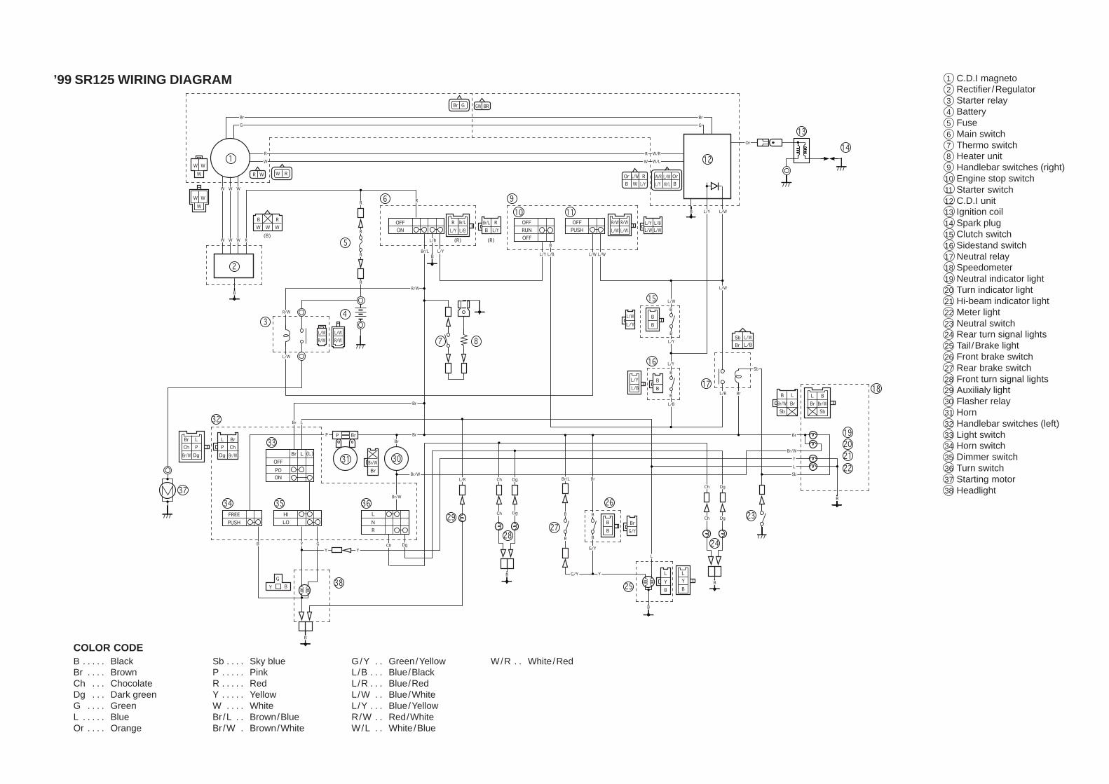
COLOR CODEB Black. . . . . Br Brown. . . . Ch Chocolate. . . Dg Dark green. . . G Green. . . . L Blue. . . . . Or Orange. . . .
Sb Sky blue. . . . P Pink. . . . . R Red. . . . . Y Yellow. . . . . W White. . . . Br /L Brown/Blue. . Br /W Brown/White.
G/Y Green/Yellow. . L/B Blue/Black. . . L/R Blue/Red. . . L/W Blue/White. . L/Y Blue/Yellow. . . R/W Red/White. . W/L White/Blue. .
W/R White/Red. .
1 C.D.I magneto2 Rectifier /Regulator3 Starter relay4 Battery5 Fuse6 Main switch7 Thermo switch8 Heater unit9 Handlebar switches (right)10 Engine stop switch11 Starter switch12 C.D.I unit13 Ignition coil14 Spark plug15 Clutch switch16 Sidestand switch17 Neutral relay18 Speedometer19 Neutral indicator light20 Turn indicator light21 Hi-beam indicator light22 Meter light23 Neutral switch24 Rear turn signal lights25 Tail/Brake light26 Front brake switch27 Rear brake switch28 Front turn signal lights29 Auxilialy light30 Flasher relay31 Horn32 Handlebar switches (left)33 Light switch34 Horn switch35 Dimmer switch36 Turn switch37 Starting motor38 Headlight
’99 SR125 WIRING DIAGRAM