formal assurance certifiable tooling strategy final … assurance certifiable tooling strategy final...
TRANSCRIPT
February 2017
NASA/CR–2017-219372
Formal Assurance Certifiable Tooling Strategy Final Report Eric Bush Kestrel Technology, LLC, Palo Alto, California David Oglesby, Devesh Bhatt and Anitha Murugesan Honeywell Aerospace Advanced Technology, Golden Valley, Minnesota
Eric Engstrom, Joe Mueller, and Michael Pelican Smart Information Flow Technologies, Minneapolis, Minnesota
https://ntrs.nasa.gov/search.jsp?R=20170002595 2018-05-13T20:00:45+00:00Z

NASA STI Program . . . in Profile
Since its founding, NASA has been dedicated to the advancement of aeronautics and space science. The NASA scientific and technical information (STI) program plays a key part in helping NASA maintain this important role.
The NASA STI program operates under the auspices of the Agency Chief Information Officer. It collects, organizes, provides for archiving, and disseminates NASA’s STI. The NASA STI program provides access to the NTRS Registered and its public interface, the NASA Technical Reports Server, thus providing one of the largest collections of aeronautical and space science STI in the world. Results are published in both non-NASA channels and by NASA in the NASA STI Report Series, which includes the following report types:
• TECHNICAL PUBLICATION. Reports of
completed research or a major significant phase of research that present the results of NASA Programs and include extensive data or theoretical analysis. Includes compila- tions of significant scientific and technical data and information deemed to be of continuing reference value. NASA counter-part of peer-reviewed formal professional papers but has less stringent limitations on manuscript length and extent of graphic presentations.
• TECHNICAL MEMORANDUM. Scientific and technical findings that are preliminary or of specialized interest, e.g., quick release reports, working papers, and bibliographies that contain minimal annotation. Does not contain extensive analysis.
• CONTRACTOR REPORT. Scientific and technical findings by NASA-sponsored contractors and grantees.
• CONFERENCE PUBLICATION. Collected papers from scientific and technical conferences, symposia, seminars, or other meetings sponsored or co-sponsored by NASA.
• SPECIAL PUBLICATION. Scientific, technical, or historical information from NASA programs, projects, and missions, often concerned with subjects having substantial public interest.
• TECHNICAL TRANSLATION. English-language translations of foreign scientific and technical material pertinent to NASA’s mission.
Specialized services also include organizing and publishing research results, distributing specialized research announcements and feeds, providing information desk and personal search support, and enabling data exchange services.
For more information about the NASA STI program, see the following:
• Access the NASA STI program home page at
http://www.sti.nasa.gov
• E-mail your question to [email protected]
• Phone the NASA STI Information Desk at 757-864-9658
• Write to: NASA STI Information Desk Mail Stop 148 NASA Langley Research Center Hampton, VA 23681-2199
National Aeronautics and Space Administration Langley Research Center Prepared for Langley Research Center Hampton, Virginia 23681-2199 under Contract NNL14AA06C
February 2017
NASA/CR–2017-219372
Formal Assurance Certifiable Tooling Strategy Final Report Eric Bush Kestrel Technology, LLC, Palo Alto, California David Oglesby, Devesh Bhatt and Anitha Murugesan Honeywell Aerospace Advanced Technology, Golden Valley, Minnesota
Eric Engstrom, Joe Mueller, and Michael Pelican Smart Information Flow Technologies, Minneapolis, Minnesota
Available from:
NASA STI Program / Mail Stop 148 NASA Langley Research Center
Hampton, VA 23681-2199 Fax: 757-864-6500
The use of trademarks or names of manufacturers in this report is for accurate reporting and does not constitute an official endorsement, either expressed or implied, of such products or manufacturers by the National Aeronautics and Space Administration
1. Project Overview ......................................................................................................... 2 2. Theoretical Soundness Issues (Task 4.1) ................................................................... 3
2.1 Soundness Issues for Model Checking (Task 4.1.1) .............................................. 3 2.1.1 Typical Use Cases .......................................................................................... 4 2.1.2 Sources of Error .............................................................................................. 6 2.1.3 Downstream Impacts ...................................................................................... 7
2.2 Soundness Issues for Static Analysis (Task 4.1.2) ................................................ 7 2.2.1 Typical Use Cases .......................................................................................... 8 2.2.2 Potential Sources of Errors under Use Cases ................................................. 9 2.2.3 Implementation and Interpretation Issues ...................................................... 10 2.2.4 Downstream Error Impact ............................................................................. 11
2.3 Soundness Issues for Intermediate Representations (Task 4.1.3) ....................... 12 2.3.1 Input Models and Internal Abstractions ......................................................... 12 2.3.2 Completeness of the Assurance Case .......................................................... 12 2.3.3 Tool Chain Considerations ............................................................................ 12
3. Case Studies of Tool Qualification under DO-330 (Task 4.2) .................................... 13 3.1 Case Study Preparation (Task 4.2.1) ................................................................... 13 3.2 Tool A and B Case Studies (Tasks 4.2.2 and 4.2.3) ............................................ 15 3.3 Tool Life Cycle Impact Analysis (Task 4.2.4) ....................................................... 17
3.3.1 DO-330 Objectives ........................................................................................ 17 3.3.2 Areas of Outstanding Need ........................................................................... 17 3.3.3 Failure Modes and Effects Analysis............................................................... 18
3.4 Case Studies Conclusions ................................................................................... 20 3.4.1 Hurdles to the Adoption of Research Tools ................................................... 20 3.4.2 Importance of Error Handling ........................................................................ 20 3.4.3 Treatment of Incomplete Results ................................................................... 20 3.4.4 Use of Unqualified Tool Capabilities .............................................................. 20 3.4.5 Dependence on Third Party Tools ................................................................. 20
4. Risk Mitigation Strategies (Task 4.3) ......................................................................... 21 4.1 Dissimilar Redundant Tools (Task 4.3.1) ............................................................. 21 4.2 Similar Redundant Tools (Task 4.3.2) .................................................................. 22
4.2.1 JPF V1 vs. SPIN ........................................................................................... 22 4.2.2 JPF V2 vs. SPF ............................................................................................. 22 4.2.3 CodeHawk vs. Coverity ................................................................................. 23 4.2.4 Multiple back-end SMT solvers ..................................................................... 23 4.2.5 SMT Solver compatibility via SMT-LIB .......................................................... 23
4.3 Tool Self-Tests and Benchmark Propagation (Task 4.3.3) ................................... 24 4.3.1 Tool Self Tests .............................................................................................. 24 4.3.2 Benchmark Propagation ................................................................................ 24
4.4 Tool Lifecycle Enhancements (Task 4.3.4) .......................................................... 25 4.4.1 Tool Input/Output/Execution Checking and Proof Checking Approaches ...... 25 4.4.2 Tool Life Cycle and Qualification Considerations........................................... 29
4.5 Safety Case Argument Templates (Task 4.3.5) ................................................... 29 References ................................................................................................................... 31
1

1. Project Overview The overall theme of this research project was to investigate issues and provide guidance
for the qualification of formal methods tools under the DO-330 qualification process. It consisted of three major subtasks spread over two years: 1) an assessment of theoretical soundness issues that may affect qualification for three categories of formal methods tools, 2) a case study simulating the DO-330 qualification of two actual tool sets, and 3) an investigation of risk mitigation strategies that might be applied to chains of such formal methods tools in order to increase confidence in their certification of airborne software.
Details of the results from each of these three subtasks can be found in the four interim
report deliverables produced under separate covers: Theoretical Soundness Issues Report (deliverable 2), Case Study Preparation Report (deliverable 3), Tool Qualification under DO-330 Case Studies (deliverable 5), and Risk Mitigation Strategies Report (deliverable 6). This Final Report will summarize the activities and results of the three major subtasks.
2

2. Theoretical Soundness Issues (Task 4.1) Formal methods tools are typically based on the rigorous, underlying semantics of the
software on which they operate, and are thus often able to guarantee that their results are always correct. This sets them apart from more traditional tools, and creates some unique considerations for their qualification. Key among these is their default presumption (as a class) of soundness. We have discussed the issues of soundness in tool qualification, both theoretical and practical, for formal methods tools in general as a combined team, and investigated the aspects of soundness that apply to our particular classes of tools as separate teams that specialize in these classes. The details of this study are contained in the Theoretical Soundness Issues Report (submitted under separate cover). Below is a summary of the soundness issues addressed by each of the subtasks.
2.1 Soundness Issues for Model Checking (Task 4.1.1)
Model checking software checks whether a model satisfies a property or can perform a specified behavior for formal models that typically represent computer hardware or software. If a given property is proven false, most model-checking algorithms will identify a counterexample that shows the path of execution that leads a model to the property violation, which usually represents an undesirable error state. Hence, the counterexample helps lead to the root of the problem. Model checking is a dynamic analysis process that systematically checks whether a property holds for a given state. It enumerates, or in some cases “symbolically executes,” all possible states of the world. Unfortunately, this enumeration comes with the state explosion problem. Even so, early model checking techniques, originally intended for verification of finite-state concurrent software systems, were adapted to other domains. Some of the first practicable uses of model checking were applications of hardware verification. In hardware verification, the finite state restriction comes naturally and thereby avoids many of the issues of scale that befall software verification. Regardless of the state-space problems, careful use of model checking techniques still provide tangible results in both hardware and software verification.
Heavily influenced by parallel research areas, modern software model checkers bear little resemblance to the original concepts for verifying finite-state concurrent systems. They developed out of the logic and theorem proving community and aim for both completeness and soundness. Their primary focus is on maintaining soundness, and will compromise on completeness by acquiescing on exploring an entire model. Despite this, they still work toward overcoming the fundamental state explosion problem. Extended and adapted to different domains over years of extensive research, software model checking use includes a panoply of techniques to these ends, as discussed in our Theoretical Soundness Issues report [12]. Additionally, more recent adaptations of model checkers include use of abstract interpretation and decision procedures, especially in the form of Satisfiability Modulo Theories (SMT) solvers. Taken as a whole, the field of Software Model Checking is a very broad umbrella covering a wide variety of tools and techniques. For instance, some work towards property falsification (“bug-finding”) and others towards verification. In the case of the former, a “positive” claim proves the existence of an error, often with a counter-example, but proves nothing if no claim can be made; conversely, verification approaches explore a superset of actual model executions, with positive claims about the model holding for all actual expansions of the model, but a violation of the property proves nothing about the original model.
In our Theoretical Soundness Issues report [12], we give an overview of broad classes of model checkers, typical use cases for model checking of software systems, as well as limitations of model checking with special emphasis on the usefulness in the realm of certification of safety-critical systems. We provide a summary of that overview in this section. As an exemplar, we will refer to Java PathFinder (JPF) and related extensions to JPF. Briefly, JPF started as a (executable) software model checker for Java bytecode, but unlike a normal Java VM, JPF identifies points in the bytecodes from where execution could proceed differently (i.e.
3
branch points), then JPF systematically explores all possible execution paths. Typical branching points include conditional (if-then) branching, scheduling sequences, and random values, but JPF has been augmented with different execution modes and extensions that include a variety of model-checking and symbolic-execution modules. While we use JPF as an example, we also note that important issues arise when considering what questions we want to ask is tightly coupled with the choice of tool and techniques used for model checking.
2.1.1 Typical Use Cases
The typical use case for model checking in general is to prove temporal properties about models of system behavior. Most often applied to concurrent systems models, the properties of most common interest include detection of deadlocks, buffer overflows, data access or race conditions, and termination or reachability properties. The input models are typically refined from a higher-level design artifact or abstracted from lower-level (implementation or) executable representation, and properties to be proven are usually derived from the software system requirements.
In contrast to theorem proving, model checking’s primary advantages are that it is completely automatic and relatively fast, and that it can usually produce counterexamples when the properties are proven false. As compared to static analysis, model checkers can be more complete in terms of exploring all possible executions, but at the expense of time, space, and complexity of input.
Generically, all uses cases of model checking can be broken into two categories: invariant (“safety”) and reachability (“liveness”) properties. These properties are typically represented via a temporal logic expression. In addition to each model-checking tool having its own unique language and semantics, the temporal logic specifications come in different flavors as well. Most are based upon either Linear Temporal Logic (LTL) or Computational Tree Logic (CTL), both of which have been shown to be a subset of CTL*. While there are some expressions that are not representable in LTL but can be stated in CTL and vice-versa, in general LTL is easier for less versed users to specify and understand. Regardless, most property specification languages include the ability to specify propositional logical expressions augmented with temporal operators including Globally/Always, Finally/Exists (eventually), Next-State, Until, Weak-Until/Release. Some logics augment with bounded-time operations, probabilistic operators, or other operators.
2.1.1.1 Model Checking Properties
The primary goal of any software model checker is to prove properties with respect to a model of execution. The model may come from many sources, but is generally a finite-state model refined from a higher-level design artifact or abstracted from lower-level (implementation or) executable representation. Properties are typically (a) simple assertions, that state that a predicate over a finite-set of model variables holds whenever the execution of the model reaches a particular location, or (b) global invariants, where certain predicates will hold for all reachable states, or (c) reachability properties, that state that there exists some execution trace will eventually reach a given state.
Model-checker properties are generally classified as either safety- or liveness-properties. Informally, safety properties claim that “bad things” never happen during any program execution, whereas liveness properties show that “good things” always eventually occur. With both the model and property, the simplest form of verification is performed by exhaustive state-space search of the combined model and (negation of the) property specification. Thereby the verification problem becomes a search problem, with reachability of the encoded property states thereby yielding a path to a counter-example to the property. However, other strategies exist, which we will elaborate upon.
4
2.1.1.2 Model Checking Techniques
Typically model checking techniques work toward soundness, and most either sacrifice completeness or acknowledge the state explosion problem but operate over small enough domains that it does not pose a problem. We identify main categories of model checking techniques: Explicit-state model checking, abstraction, reductionist, bit-state hashing, bounded model checking, compositional reasoning, symbolic model checking, and execution exploration.
The simplest forms of model checkers effectively search the program space or model states and transitions, unified with a state-representation of the verification properties, using various graph traversal techniques. This method effectively enumerates all possible states and transitions of the program. Typical explicit state model checkers construct the state-space on the fly, checking properties of interest after each state transition. As might be expected, the most fundamental flaw in explicit-state model checkers is that the expanded state space of a model can be exponentially larger than the description of that model. Given that most software is more dynamic and flexible than more structured hardware, software verification poses particular problems for this methodology of model checking. Therefore, ameliorating state explosion has been a major direction of research in model checking, yielding many techniques, each with its own advantages and disadvantages.
Abstraction is the most common and essential technique for making verification assessments tractable, especially those that might otherwise contain unbounded data types or infinite state spaces. Abstract model checking is still a reachability search problem, but the analysis is performed on an abstract domain that captures some, but not all, of the behaviors or state representation of the ‘real’ system. A proof (or violation) in the abstract domain indicates the verification (or bug) of the desired safety property in the original domain. Abstractions can be the largest source of incompleteness and unsoundness. For completeness, it is imperative that the abstraction retains the necessary elements to correctly represent the desired (or violated) behavior. It will be missed otherwise. For soundness, often the burden falls to the human author of the model to ensure the abstraction corresponds with the original model.
Reductionist techniques are a particularly effective, largely automated means to increase the scale of model checking. By exploiting the independence of potential state transitions over non-intersecting state variables, partial-order reduction can ignore the order of these independent transitions. Partial-order reduction techniques maintain soundness while significantly reducing the size of the completely unrolled state-transition space. Symmetry reduction is similar to partial-order reduction. Symmetry reduction is applicable most often in finite state concurrent systems, which often contain repeated (sub-) components. Symmetry reduction finds the symmetries in the model and explores the state space of only one example of each class.
Whereas most uses of reductionist techniques maintain completeness and soundness of the analysis, some uses of model checking for falsification (bug-finding) give up on either soundness or completeness of the search. Bitstate hashing is a common technique in which the hash of each state is stored, rather than the actual state itself. Bitstate hashing is both unsound and incomplete because two distinct states may hash to the same hash value (a hash collision). Bounded model checking is another technique applied in symbolic model checking that trades completeness for effective checking of safety properties and bug finding. In bounded model checking, a (Boolean) formula is checked for satisfiability with respect to a finite-sequence of state transitions of length k. If reachability (satisfiability) cannot be proven, the search is continued for a larger k. This method remains symbolic in that a check for paths of length k covers all possible values of the variables encoded in the underlying representation of the model. If a solution from the solver is found, that assignment of values to the variables forms the basis for a counterexample.
Compositional reasoning exploits the ability to decompose the problem thereby reducing the scale of the state-space explored during verification of each of the subcomponents. We reduce the verification problem by divide-and-conquer, decomposing the original larger model into smaller sub-models such that the results of model checking sub-models can be combined to
5
prove properties about the original model. Simplistically, if each of the sub-model properties are provable and the conjunction of those lower-level properties implies a higher-level specification, then the complete system must also satisfy that higher-level specification. In theory these techniques may make tractable otherwise intractable model-checking problems.
While explicit-state techniques are the archetype of software model checking, symbolic model checking, sometimes called implicit model checking, developed as an alternative to address the state-space explosion problem. In symbolic model checking, model-checkers manipulate representations of sets of states rather than individual states, and perform the state-space search by the transformation of these symbolic representations. Symbolic representations can be much more succinct than an explicit enumeration of all states, and can represent an infinite state-space. Moreover, checking of verification properties can often be done with constant-time using underlying constraint solvers.
As a special case of explicit-state verification, execution exploration uses the runtime system of an executable to explore the state-space of the model. Java PathFinder (JPF) is an example in this category. In this case, the model is typically source code, virtual machine byte code, or even (compiled) machine code. The execution environment is a specially built “runtime” for (a subset of) the source language, a modified virtual machine, or a (modified) OS scheduler. In all cases, the non-determinism comes from two sources: (user) inputs from the environment, and branch-points and scheduler context switches from the code/model. This approach benefits from explicit-state representation because the semantics of the modeling language are the semantics of the programming language itself; there is no translation gap between the intended design and what is being executed in the form of code. Additionally, when a counter-example is generated, a concrete execution demonstrating the failed property (i.e. a bug) can be directly provided to the user. However, because we are using the execution environment for state space exploration, now the state of execution may necessarily include additional variables, such as machine registers, the heap and stack, as well as other aspects of machine execution that can be avoided when performing verification using a special purpose modeling language with unique semantics.
2.1.1.3 Java PathFinder (JPF) and Symbolic PathFinder (SPF)
Java PathFinder (JPF) is an extensible framework for verification of Java bytecodes. While JPF began as an explicit-state model checker, the code has evolved until it is now more of a framework within which multiple plug-ins exist to perform different forms of model-checking related analyses. JPF-core is still an explicit-state model checker capable of automated detection of deadlocks, data race conditions and assertions (equivalent to safety property) violations. The core also uses typical explicit-state scalability techniques including one-the-fly exploration and partial order reductions. JPF has been extended to include a symbolic execution plug-in, Symbolic PathFinder (SPF), that combines symbolic execution, model checking and constraint solving to better handle dynamic inputs, loops, and recursion. In addition, SPF has been used to generate test cases that can guarantee coverage of all possible paths through the code relative to a set of (potentially symbolic) inputs. We selected JPF because of the broad support for different model checking techniques, independent of the JPF’s reliance on models written in Java. Even though Java is not the language of choice for many safety-critical systems, the feature set of JPF is broad enough to provide an overview of different model checking options.
2.1.2 Sources of Error
While model checking is typically slower but more precise than static analysis, the single largest source of error in model checking are the model and properties themselves. Regardless of the source of error, we can classify the types of errors into two camps: False Negatives, real, undiscovered bugs in the model, and False Positives, report of errors that do not actually exist. The latter are usually deemed somewhat “acceptable” in that reporting of an error that does not exist encourages further examination, often resulting in modification of the model or property to
6
exclude false behaviors. On the other hand, too many false positives and the tool may become useless. In contrast, false negatives are the most important class of error in the use of a model checker, in that they represent true errors in the model that are undetected and unreported.
Modeling languages are often formed for a single model checker, and these languages have their own specification and semantics that are necessarily different from machine-level specifications. Hand-written models in these languages may inadvertently exclude potential behaviors. The challenge is to ensure the model being analyzed is a true and accurate representation of the desired system behavior. Even in JPF, the model may be a source of error. JPF operates on Java byte-codes, but still the “model” under assessment is not usually the actual executable code due to abstractions that must be made.
Closely related to errors of modeling, errors in the testing environment can result in false negatives. Since the model itself may be only a partial specification, it is often required to define a “test harness” or stubs for other behaviors. These stubs necessarily provide only partial implementation of the true behavior of the eventual system to reduce complexity, or pass unknown model components. Therefore it may be possible that not all paths through the model being analyzed are properly checked, again leading to false negatives. In JPF, stubbed behaviors are often used in place of calls to system and library functions.
While the modeling languages for most model checkers are usually fairly similar to other programming languages, property specifications are much more complex, especially for the naïve user of a model checker. Both LTL and CTL, common languages for property specifications, require a great deal of care to ensure that properties written are both a correct representation of the requirement being checked and not trivially true given the model being analyzed. Many tools have default or “basic” properties pre-encoded (e.g. deadlock detection), and others, JPF included, allow one to directly represent some classes of safety properties directly into the model by means of much more intuitive assertion statements. However, these can be insufficient to fully capture all potential behaviors of interest, so we must still rely on more complicated temporal logic languages.
2.1.3 Downstream Impacts
As described above, model checking is often an exercise in analysis of design-level artifacts. Numerous studies have show that errors found and corrected at design time result in many fewer bugs and less rework when it comes to implementation. Unfortunately, model checking is not a silver bullet in this regard as the model and properties are as subject to “bugs” as the eventual implementation. Automated model extraction or using a model checker that operates on a low-level implementation can reduce the risk of errors in modeling. Similarly, providing pre-defined properties or tools that assist the analyst in specifying (temporal) properties can reduce that source of errors as well. Finally, overcoming the state-space problem via abstractions and test harnesses is a common source of errors.
Secondarily, the choice of model checker tool and which features to enable in the tool are highly contextual to the analysis to be performed. The old adage, “a fool with a tool is still a fool” is no less apt in this regard. Misinterpretation of the lack of an error report (false negative) with a misconfigured tool is common.
While modeling and property specifications are somewhat challenging, model checking is still one of the best, automated techniques for finding errors, especially those involving concurrency and inter-process communications.
2.2 Soundness Issues for Static Analysis (Task 4.1.2)
The term static analysis is often used to classify analyzers in contrast to dynamic analysis. Informally, dynamic analyzers examine the runtime behavior of a program along one path as it is executing (typically with instrumentation). Statics analyzers, it is said, don’t execute the program, but rather infer properties of interest from the syntactic form of the program alone. This is perhaps not the best choice of terms because some static analyzers, e.g., abstract
7

interpreters, achieve their results by symbolic execution or interpretation. For these tools, it is not a static/dynamic distinction (execute/don’t execute), but an abstract/concrete distinction in how the execution is performed. A more inclusive criterion for static analyzers would be that they analyze programs in the absence of actual inputs. Such analyzers necessarily must consider all execution paths.
The best-known category of static analyzers with a formal basis for soundness is the abstract interpreters. Since it is almost always infeasible to execute a program over all of its possible paths, these tools interpret an abstract version of the program over abstract sets of data values. These two abstractions (and fixpoint iterators) allow for breadth-first execution to consider all program paths in parallel, at the expense of some imprecision in the characterization of the program’s behaviors. In the best case, a desired property of the program can be proved to hold for this safe over-approximation of the actual behaviors, in which case, it necessarily holds for the actual behaviors as well.
For this study, we used Kestrel Technology’s CodeHawk abstract interpretation system as the exemplar of a formal methods static analyzer.
2.2.1 Typical Use Cases
The generic use case for abstract interpretation is to prove a conjecture about whether a module of software will never, will always, or may execute some behavior of interest. This can be a conjecture about behavior or intermediate data values at specific program locations, or about all possible locations. The typical use cases for CodeHawk, so far, have revolved around verifying cyber security properties of software. This reflects a defensive posture of assuring that software doesn’t contain weakness or bugs that may be exploited by an adversary. But these same weaknesses or bugs can also be the cause of software failure on their own, so the broader class of use cases is concerned with determining software safety. Kestrel’s CodeHawk technology is currently realized in three separate, generic analyzers for C, Java, and x86 binaries, and several special-purpose tools for analyzing properties specific to particular domains. Below are typical use cases for each of the language analyzers, and one domain-specific analyzer
2.2.1.1 Memory Safety
The most substantial use case for the C version of CodeHawk, so far, has been a DHS project for proving the memory safety of C applications. This was a comprehensive study covering every location in the software at which an undefined memory access is possible according to the C language standard. Undefined memory access covers all of the categories of overflow, underflow, array bounds, null pointers, undefined pointers, string buffer overlaps – for reading and writing. Since the C compiler cannot guarantee such accesses will not occur for certain types of references, C programs with such exposures are potentially vulnerable to exploitation and attack. Abstract interpretation is used to attempt to prove that a program has no such vulnerabilities, by attempting to prove that the computed abstract invariants on data values, at every reference in the program, satisfy all declared bounds and initialization preconditions.
Proving memory safety in C programs is a perhaps the most typical use case for all C abstract interpreters. The DHS project illustrates two variations on this theme: automatically proving safety conjectures, at low cost, for large portions of many programs (a large gain in coverage and confidence over other verification methods); and exhaustively proving these conjectures with human assistance, at great expense, over a few programs (achieving soundness and completeness for a reference standard).
2.2.1.2 Data Flow from Sources to Sinks
A use case for the Java version of CodeHawk is illustrated by its role in the DARPA Stone Soup program. In this case, it was paired with a dynamic analyzer for finding and fixing exposures in Java programs to SQL injection attacks. The ‘taint’ domain was used to
8
exhaustively trace the dataflow from external sources (sources of possibly tainted, or malicious, SQL strings) to internal SQL calls. Such call locations whose abstract input invariants include the taint value need to be remediated by editing or type checking guards to ensure that SQL will not be called with pernicious strings. Although this particular application of the technology was aimed at SQL attacks, the taint domain can be used to trace the data flow of arbitrary properties from sources to sinks.
2.2.1.3 Reverse Engineering
Use cases for the binary (x86) version of CodeHawk are interestingly different than those for higher-level languages. In 3GLs, like C and Java, variables are defined and referenced symbolically, as are program locations that are the targets of control flow constructs (such as do and goto). This allows the compilers for these languages to restrict programmer access to the actual binary addresses of the resulting machine-language program (for reading, writing and branching). The compiler provides a reasonable guarantee that the translated binary-level accesses will conform to the symbolic declarations of the input program. For this reason, the front-ends that translate 3GL programs into CodeHawk’s abstract CHIF form can rely on the symbolic indirection of the programming language semantics to produce an equivalent abstract program (modulo abstraction). A reasonably well-defined concrete program is translated into an equivalently well-defined abstract one.
In the case of binary programs, all bets are off. Variables and non-contiguous control transfers may have been implemented or changed by programmers, even if first compiled. The CHIF front-end must first discover variables and branch targets and distinguish between bytes that implement instructions vs. data vs. padding. For this reason, the first, essential use case for binary abstract interpretation is reverse engineering – discovering the semblance of a concrete program with stack and heap variables in addition to the registers, that can be turned into an abstract one.
2.2.1.4 Range Bounds for Digital Filters
A use case of CodeHawk that is directly relevant to the aerospace domain is its role in an AFRL project to verify the output range bounds of digital filters. A specialized version of the C CodeHawk analyzer has been implemented to analyze C functions implementing such filters, given some additional constraints about the filter implementation and intended numerical constraints on its inputs. These input assumptions, and the C filter code, are generated from formal models of the filters by Honeywell’s HiLiTE tools. A custom integration pathway allows these input constraints, and desired conjectures from the model about the filter’s output ranges, to be piped directly into CodeHawk. A new domain of reals specialized to their floating point implementations has been added to CodeHawk so that floating-point rounding effects can be accounted for in the analysis. CodeHawk then computes abstract invariants over the output values and attempts to prove the output range conjectures.
2.2.2 Potential Sources of Errors under Use Cases
In this section, we focus on the two uses cases above that are most relevant to tool qualification under DO-178C – the two involving C source code. With the exception of the reverse engineering of binaries use case, CodeHawk performs a (theoretically) sound analysis, which means we expect no errors in the reported results. But since each use case specializes the CodeHawk framework to a specific analysis problem, tool users are not always aware of the assumptions and boundaries of the specific analysis. This can lead to erroneous assumptions and expectations about the results.
2.2.2.1 Memory Safety
In the memory safety use case for C programs, all program locations involving memory access are subjected to a proof of memory safety using the computed (abstract) invariants at each location. Because the analysis is sound, all locations proved safe, are safe. The remaining
9

locations, however, are not necessarily unsafe. If this unproven class of locations is large, it can create the erroneous expectation that the analyzed program has lots of bugs that must be fixed. A more productive approach might be to focus the analyzer on just the remaining cases using a more expensive, precise domain.
From the converse perspective, the analyzer will be complete with respect to unsafe locations (all unsafe locations are included in the set of unproven locations). A user of the analyzer can rely on its soundness to exclude all the safe locations from further scrutiny for safe memory access. But failure to appreciate how the class of safe memory access is related to all possible classes of program errors can lead to overconfidence in the results – assuming that no errors (of any kind) remain in the safe memory locations.
2.2.2.2 Range Bounds for Digital Filters
The specialized CodeHawk analyzer for digital filters is an atypical use case in that it uses assumptions from an external formal tool (Honeywell’s HiLiTE) as an essential part of the abstract interpretation process. Filters are a class of numerical algorithms for which the normal widening process of abstract interpretation is not particularly useful. Generic, conservative bounds used in widening will generally yield bounds on the filter’s output that are much wider than known analytic results that can be derived mathematically from the formal specification of the filter’s class (the recurrence relation and coefficients). Accordingly, the analysis is specialized to particular classes of filters, and exploits the known analytic results for the class during the widening and convergence process.
A sound analysis, in this case, is thus predicated on correct information being supplied from the outside. The collection of filter class characteristics are provided only once, and become part of the implementation when the analyzer is built, so these are generally well vetted. At runtime, however, the call to analyze a particular filter instance will be accompanied by instance-specific filter parameters (including its algorithmic class) and presumed bounds on the inputs to the filter. CodeHawk will assume these values to be true, and the correctness of the computed (abstract) output bounds on the filter will be conditional on this correctness assumption.
A more pervasive source of error in the abstract interpretation of numerical algorithms comes from the analyses typically being performed over the mathematically ideal domains of real or rational numbers. The C code that implements the algorithms will be employing floating-point numbers, which will have the capacity for precision and round-off errors not present in the reals. So analytic results computed over the reals may not always hold for their corresponding floats. To cover this possibility, this particular project also does an abstract interpretation of the filters over an abstract domain of floating-point intervals. The computed bounds from the real analysis are then compared to those for the floating-point analysis to expose possible error bounds.
2.2.3 Implementation and Interpretation Issues
CodeHawk is an abstract interpretation technology rather than a specific analysis tool. The core technology is agnostic about the language of the programs it analyzes and the sorts of conjectures one attempts to prove. It accepts an abstract program, and computes abstract invariants over variables at every (abstract) program location requested. To use this technology to prove particular program properties, it must have a front-end translator to parse the program’s language and abstract relevant executable statements into CodeHawk’s internal operations (CHIF) that expose the variables of the conjectured property, a specification of iterators and domains to be used, and a back-end module that attempts to prove the conjectured property using the computed invariants.
Parts of the front and back ends can be implemented once and reused, for instance, the parser for each programming language, and the general-purpose proof procedures. These modules can contain errors, but because they implement known, standard algorithms, and are used (and thus tested) many times, confidence in their soundness is high. But other portions of
10

these surrounding modules are custom-written for each analysis problem. These are the portions that interpret the parsed input program to choose the parts that are relevant for abstract interpretation and set up the properties to be proved. The soundness of these interpretations is a function of the skill of the analyst who programs the particular analysis. Flaws in this interpretation, e.g. incorrect assumptions about operational language semantics, omitting portions of the program that bear on the invariants, incorrect design of custom abstract operations, can produce an incorrect result, even if the implementation of the more permanent portions of the analyzer are sound.
A CodeHawk-derived analyzer, like any computer program, is originally written by humans, and thus subject to the standard exposure to implementation errors – either errors that cause it produce incorrect results, or errors that cause the analyzer to abnormally terminate or fail. Its exposure to such implementation errors, however, is minimized by several characteristics. It is written in Ocaml, a very high level, strongly typed, functional language that minimizes the conceptual distance between algorithm specification and executable code. The central abstract interpretation engine, and the permanent parts of the front and back ends, are implemented according to well-known algorithms from the literature. These algorithms generally have their own proofs of correctness, so the remaining exposure is to flaws in their representation as Ocaml programs.
As with the exposure to interpretation errors in the writing of the non-permanent parts of a complete analyzer detailed above, these non-permanent parts are also more exposed to implementation errors, both because they are custom designed (not following published algorithms), and because they get less exposure to use and testing due to their ad hoc nature.
2.2.4 Downstream Error Impact
Internal implementation errors that may cause abstract interpreters, such as CodeHawk, to fail at runtime, or to fail to terminate at runtime, have no specific effects on other tools downstream in the software lifecycle. In these cases, there is no analysis result produced. So there is no result about which to be wrong. The situation is the same as if the tool had not been run at all. Internal implementation errors that may compromise the abstract interpreter’s soundness, however, can be expected to have a downstream impact. One runs an abstract interpreter to prove that a program has certain properties, or the absence of certain properties. The claim of soundness can lead tool users to place extraordinary trust in the results, and thus more likely to omit other downstream verification steps that would be theoretically redundant.
Perhaps the greatest downstream exposure to soundness errors is faced by testing. It would be rare (and unwise) to find an organization so trusting of soundness claims that they forego testing of safety-critical software after a favorable analysis result. If the analyzer is sound, then a later test for the same property just proved would be redundant. But the defeasible nature of tool implementations should qualify this confidence. An organization may, however, perform less testing of non safety-critical software, or allocate limited testing resources to other properties and programs, in the wake of a favorable upstream result from abstract interpretation. These are reasonable, practical choices that nevertheless expose an organization to the possibility of unsoundness. Another downstream exposure to unsound abstract interpretation can result from removing runtime checking code from a performance-sensitive application because such checks are deemed unnecessary.
A different kind of downstream error impact can result not from analyzer errors per se, but from an abstraction gap between real (or rational) numbers and their implementation as floating-point numbers. Abstract interpretation is often performed on real or rational numbered domains that effectively have infinite precision. Computer approximations of reals and rationals as floating-point numbers necessarily have a machine-word imposed, finite precision, and thus will eventually produce round-off errors when this precision is exceeded. So the abstract interpretation may be sound, producing an error-free result over the reals/rationals that does not carryover to the floats.
11
Because it deals in over-approximations, upstream use of abstract interpretation can lead to downstream interpretation errors, even though the upstream analysis is sound. If the abstract interpretation is overly coarse-grained, catching many acceptable program behaviors in its safe approximation, unnecessary testing and code reviews may be deemed necessary downstream to probe this over-exposure.
2.3 Soundness Issues for Intermediate Representations (Task 4.1.3)
The Intermediate Representation task has really been about the whole lifecycle, the issues that can lie dormant, and ideas for exposing problems between tools. These are based in our other research and experience applying multiple qualified tools for certification of systems. We looked at the obvious concerns about translating or creating inputs to formal tools, the completeness of the assurance case, and how a tool chain can take advantage of diversity to uncover problems.
(Note: We have only briefly summarized the soundness issues for intermediate representations here. Unlike soundness issues and potential errors related to tools that are more readily understandable, intermediate representation issues are difficult to describe clearly at a medium level of detail. We refer the reader to the Theoretical Soundness Issues Report, section 5.8, where these issues are described in more detail and in the context of the certification process, using examples.)
2.3.1 Input Models and Internal Abstractions
The obvious concern for most formal tools is that they operate on their own models of the system. These models must be verified for correctness against the system and containing the detail necessary to prove the properties that satisfy the claimed objectives. The methods involved require a deep understanding to recognize what types of errors can lead to false proofs and expose such problems in the input models.
Tools that take development models and source code are not immune to these concerns. However, the input artifacts are inherently correct and contain all relevant details. The qualification of such tools must exercise the full semantics of the models and code to expose differences is interpretation of these artifacts. Deploying multiple tools with independent semantic implementations can also increase confidence in the assurance case.
2.3.2 Completeness of the Assurance Case
When low-level requirements are expressed as a design model, the full enumeration of requirements is not clear. Some tools require that the developer identify the software requirements and/or test requirements to verify the model. Such tools take the definition of those requirements at face value. As long a test is generated, full coverage is claimed. A separate verification is required for each design model to verify all requirements are present. Other tools define the software and test requirements for every block in a library. Full coverage is claimed when tests cover all the requirements for all the block instances in a model. This allows for a single verification of the requirements in the block library, rather than every design model.
In addition to the requirements to be tested, the criteria to determine when a requirement is fully tested are a concern. Model coverage is not sufficient because an element may be executed without a meaningful measurement of its impact on the output being affected by the requirement. Tests must be determined to be observable and adequately controlled. The impact of a block may be masked by other actions in the model, and the result may not be distinguishable from an incorrect action.
2.3.3 Tool Chain Considerations
It is unreasonable to expect a single tool (or a single mathematical technique within a tool) to be both complete and sound for complex verification objectives. Different methods have
12
different capabilities; aligning those capabilities is a promising means to constructing a complete assurance case. It is important to understand a tool’s completeness claim independently of the tool’s soundness to prove properties. For example, is a tool proving a property correctly is a soundness consideration that involves state-space search or abstract interpretation techniques; whereas enumeration of all instances where the property applies or what are all the properties is a completeness consideration that requires other methods. Additionally, multiple independently developed tools can effectively check each other against errors in interpreting common artifacts.
3. Case Studies of Tool Qualification under DO-330 (Task 4.2) This task called for characterizing how selected formal methods tools could be qualified
under DO-330 while applying DO-333, by studying the concrete application of DO-330 qualification approaches via case studies using actual tools. We were to pick actively used formal methods tools or tool suites to use in case studies that examine the issues surrounding formal methods tool qualification. The study was to cover tool qualification level TQL-5 at a minimum, and address more rigorous TQL levels if feasible.
3.1 Case Study Preparation (Task 4.2.1)
This subtask called for choosing the two representative formal methods tools that would be the subjects for the case studies of subtasks 4.2.2 and 4.2.3 below, and preparing study methods and research questions to be applied during the case studies. We have documented this preparation activity in detail in the Case Study Preparation Report [12] produced under separate cover. The preparation consisted primarily of deciding which DO-330 objectives would be addressed and the general approach we would be taking.
The purpose of a verification tool is to automate specific activities needed to accomplish DO-178C objectives. Figure 1 shows the DO-178C verification process – the ovals and arrows contain references to DO-178C objectives and activities.
For the actual case studies, we proposed to select DO-178C objectives/activities that the tools could address, define the tool requirements that support those objectives, and carry out the tool qualification procedures relative to those requirements. These tool qualification procedures are defined in DO-330, Software Tool Qualification Considerations.
13
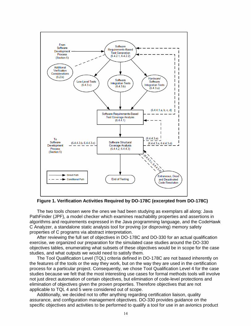
Figure 1. Verification Activities Required by DO-178C (excerpted from DO-178C) The two tools chosen were the ones we had been studying as exemplars all along: Java
PathFinder (JPF), a model checker which examines reachability properties and assertions in algorithms and requirements expressed in the Java programming language, and the CodeHawk C Analyzer, a standalone static analysis tool for proving (or disproving) memory safety properties of C programs via abstract interpretation.
After reviewing the full set of objectives in DO-178C and DO-330 for an actual qualification exercise, we organized our preparation for the simulated case studies around the DO-330 objectives tables, enumerating what subsets of these objectives would be in scope for the case studies, and what outputs we would need to satisfy them.
The Tool Qualification Level (TQL) criteria defined in DO-178C are not based inherently on the features of the tools or the way they work, but on the way they are used in the certification process for a particular project. Consequently, we chose Tool Qualification Level 4 for the case studies because we felt that the most interesting use cases for formal methods tools will involve not just direct automation of certain objectives, but elimination of code-level protections and elimination of objectives given the proven properties. Therefore objectives that are not applicable to TQL 4 and 5 were considered out of scope.
Additionally, we decided not to offer anything regarding certification liaison, quality assurance, and configuration management objectives. DO-330 provides guidance on the specific objectives and activities to be performed to qualify a tool for use in an avionics product
14
certification, including approval from certification authority. These qualifications cover planning, development, verification, and certification liaison. Since the purpose of these case studies was to explore research issues in the use and qualification of the tools, we considered only the tool qualification objectives/activities that are relevant to this research.
Our preparation called for each tool defining the DO-178C objectives against which the tool would be qualified. Since there was no target program to create a PSAC, we proposed to draft the portions of a PSAC that establish the need, the uses that require Tool Qualification Level 4, and other driving criteria for both case studies. Each case study was to produce the Tool Operational Requirements, Tool Qualification Plan, Tool Verification Plan, Tool Design Description, Tool Requirements, Tool Operational Verification and Validation Cases and Procedures, Trace Data, and Tool Operational Verification and Validation Results.
The details of our many choices were laid out in tables for D0-330 objectives T0 through T10. They described in broad strokes how we planned to address each objective for the two case studies. Some of the items were not in scope because they did not apply to TQL-4 tools; these items were identified by using a gray background color in the table row corresponding to a DO-330 objective. Other items were determined to be out of scope for the case studies primarily because they pertained to programmatic and approval issues in a certification program and thus were not relevant to the research objectives of the case studies; the specific reasons for excluding an item were described in the rightmost column of each table.
3.2 Tool A and B Case Studies (Tasks 4.2.2 and 4.2.3)
After reviewing the full set of objectives in DO-178C and DO-330 required for an actual qualification effort, we organized our case study around the DO-330 objectives tables, enumerating what subsets of these objective would be in scope for the case studies, and what outputs we would need to satisfy them. The results of this effort were a selection of qualification documents that show how existing state-of-the-art formal methods tools may be qualified using a safety-driven approach toward qualification within the DO-330 framework.
Initially, we anticipated changes to the way the formal methods tools are developed, how they are used, what claims they can make and support, and how they are integrated into lifecycle tool chains may have to be changed from current practices. Our high-level experience thus far is that qualification of formal methods tools differs little from qualification of any other tool used in the development of safety-critical systems. However, we did identify potential issues and areas of special concern, and have reported on those in our respective case study reports.
These case studies were intended to reveal issues that would become apparent during an actual qualification exercise, but might otherwise be hidden from a top-level analysis of the tools and the process. For example, during the qualification exercise, it became clear that JPF has many features suitable to an iterative test and repair approach to development, but that those features should be treated carefully when JPF is used to contribute results to a final certification for a finished software product. This issue came to light during the case study and inspired recommendations related to error reporting and internal tool limits (e.g., search depth limits).
Case studies are valuable in that they have the potential to identify more issues in tool combinations and potential mitigations. For this effort, we designed our case studies to apply appropriate limitations on software design and tool usage, and to utilize patterns of argumentation for qualification and safety case support. Using this approach, we wrote the case study documents to illustrate techniques for satisfying the tool qualification objectives.
As discussed in other documents, the use of tools to automate verification activities has direct impact on the workflow to satisfy certification objectives. For example, a verification tool may directly automate particular verification objectives/activities specified in DO-178C, and can be used to claim certification credit for those. Additionally, the use of a tool (e.g. JPF) for one objective may allow one to skip other objectives or may establish certain properties/constraints to be true such that a subsequent tool (e.g. CodeHawk) might be used in a more flexible way,
15
taking advantage of those assumptions. An extended discussion of this may be found in the FMEA portion of our results.
However, for our case study, each tool was treated separately and stand-alone. As such, we developed two independent sets of case study documents: one set for tool A (JPF), and a separate set for tool B (CodeHawk).
The scope of the case studies was focused on achieving the most insight into the actual tool qualification process for formal methods tools, while reflecting the limitations of the project. The most important restrictions were the absence of an actual flight software certification effort to inform the tool qualification, our position outside the tool development process, and the realities of project funding.
In practice, tool qualification under DO-178C is a collaboration between a tool developer and a tool user that is developing a flight software component, even if the tool developer and the tool user are part of the same organization. Since we did not have access to the tool developer for JPF, we have limited our treatment of some of the documents associated with tool design and development. Also, since our work was not motivated by a specific flight software application, we have eliminated a number of specific elements that require reference to an overarching flight certification effort. For those aspects of qualification that we did complete, we sometimes limited ourselves to a few representative examples. For example, we tried to consider a few tool requirements to a useful depth, rather than cover the full breadth of requirements necessary for a full, real-world qualification.
For each tool we produced the following set of documents in accordance with the DO-178C regime, to a level of fidelity consistent with the lack of an actual software component to be certified and our funding:
The tool-specific sections of the Plan for Software Aspects of Certification (PSAC), including DO-178C objectives, proposed product TQL, and the tools impact on the software lifecycle.
The Tool Qualification Plan (TQP) sections related to the means of qualification compliance.
The Tool & Tool Operational Requirements (TR and TOR) sections containing requirements that support the claimed objectives.
A slim Verification & Validation Cases and Procedures document containing a few representative test cases traced to requirements.
A similar sample of Verification & Validation Results tracing test execution results to the test procedures we defined.
We did not produce the following documents that would be required by an actual tool
qualification exercise associated with an actual flight software component subject to DO-178C:
The Verification Plan, for which the relevant information was covered in the TQP and the Test Cases & Procedures documents.
The Development, Configuration Management, and Quality Assurance Plans, for which the relevant objectives are not applicable to TQL 4.
The Design Description including design standards was considered to be out of scope. We did, however, provide detailed a description of the tool architectures and algorithms in other documents.
Source Code, for which the relevant objectives are not applicable to TQL 4 & 5.
Configuration Management Records, Configuration Index, Problem Reports, Life Cycle Environment Configuration Index were deemed out of scope since they are only relevant to actual software deployments and do not have any unique impacts on formal methods tools.
Quality Assurance Records, for which there are no relevant research objectives for the case study.
16

3.3 Tool Life Cycle Impact Analysis (Task 4.2.4)
This subtask called for analyzing the results of the case studies and assessing how the objectives in DO-330 Tables T0-T10 were addressed for each tool for the TQL levels being addressed and, based on this assessment, identifying areas of outstanding need where there are gaps or inadequacies in meeting DO-330 objectives. As part of this analysis task, we also produced an FMEA analysis of each of two tools separately and of the combined tool chain in which they may be embedded.
3.3.1 DO-330 Objectives
The detailed assessment of each tool’s addressing of the objectives in DO-330 Tables T0-T10 can be found in section 6 of the Tool Qualification under DO-330 Case Studies report [12] under separate cover. Of the 11 different tables of objectives, we found that only 7 of them contained objectives that were applicable to our case studies. We found that, through our case study document preparation, we were able to satisfy most of the objectives. In the above referenced report, we provide some discussion for those objectives where we identified potential gaps or complexities. A “gap” indicates that the outcome (or output) of the case study documents was found to be insufficient for supporting the corresponding objective. A “complexity”, on the other hand, suggests that some characteristics of the tool(s) make it particularly challenging to satisfy the objective.
3.3.2 Areas of Outstanding Need
We uncovered many issues related to the qualification of the two representative formal methods tools. The most in-depth treatment of each individual topic is embedded in the case study artifacts themselves. For example, in section c.1 of the JPF Tool Operational Requirements document, we include a lengthy discussion of “Development-time checking vs. verification”. That discussion will not be repeated here, but it does provide background for the conclusion that some accommodation should be made for developers to take advantage of both qualified and unqualified tool features during early stages of software development. In the JPF case study, there are over sixty separate discussions covering a range of categories, including subtleties in tool identification and configuration, problems with JPF documentation and testing, details in error handling, treatment of non-determinism, and the scalability of model-checking. Similarly, the “Tool Operational Verification and Validation Cases and Procedures Framework for CodeHawk C Analyzer (Tool B)” included in the CodeHawk case study includes extensive discussion of the relationship between the results of the recent “Gold Standard” project funded by the Department of Homeland Security and testing required for DO-330 tool qualification. For JPF the issues can be grouped into five high-level categories:
Tool identification and configuration: as the product of an active research project, JPF does not follow a release schedule or protocol. We identified a specific JPF “release” for treatment by the case study by reference to a date and source code repository commit tag. It can also be difficult to determine which modules associated with JPF are active and well maintained. (Further discussion can be found in Section A of “JPF Core: Tool Qualification Plan (TQP)”.)
Documentation: JPF documentation is in the form of an on-line wiki that covers many aspects of the JPF research endeavor beyond the core functionality that would be qualified. (Further discussed in Section G of “JPF Core: Tool Operational Requirements (TOR)”.)
Testing: Although JPF does have a set of tests, the JPF test suite seems ad hoc, including full system tests providing uneven coverage of representative program flaws. It does not include unit tests. (Further discussed in Section B of “JPF Core: Tool Verification Cases and Procedures (TVCAP)”.)
17

Error handling: our case study discusses at length the necessity for clear error messages to avoid operator error during the certification process. (Further discussed in Section F of “JPF Core: Tool Requirements (TR)”.)
Scalability: although model checking techniques constantly improve (for example, by incorporating symbolic execution techniques), an exhaustive check of all software aboard a modern airliner is beyond the capabilities of current model checking tools. To compensate, organizations using model checkers must carefully scope the system under test, possibly by checking abstractions of the final executable (such as low level requirements) or critical subsystems. (Further discussed in Section C.2 of “JPF Core: Tool Operational Requirements (TOR)”.)
The CodeHawk case study discusses similar issues. The CodeHawk C Analyzer that is the
object of the case study was produced by Kestrel Technology as part of a DHS research project. It is not a publicly released product, and has no user documentation at present. Also, because it is a research implementation, it does not yet have an externally identified accounting of error messages. There are also some issues of possible interest to the application of formal methods tools to DO-330 certified software treated only in the CodeHawk study:
Third-party tools: CodeHawk depends on the third-party tools gcc [3] and CIL [2, 1] which introduces the issues of identification and configuration of these tools, as well as the possible need to conduct similar qualification exercises for the tools. (Further discussed in Section C.7 of “Tool Qualification Plan (TQP) Framework for CodeHawk C Analyzer (Tool B)”.)
Coverage of library code: like JPF and other formal methods tools that process programming language source, CodeHawk requires extensions to handle library calls for system services for which source code may not be available for analyses. In the case of CodeHawk, there may be the need to extend the current catalog of “primary proof obligations” to cover libraries of interest to flight critical applications. (Further discussed in Section C.3 of “Tool Qualification Plan (TQP) Framework for CodeHawk C Analyzer (Tool B)”.)
3.3.3 Failure Modes and Effects Analysis
We conducted independent failure modes and effects analyses (FMEA) on both CodeHawk and JPF as well as the composed tool chain. These are provided separately as an Excel spreadsheet with tabs that show the tool chain and DO-178C credits claimed by each tool, the tool chain FMEA, and finally the individual tool FMEAs. For each tool, we composed the FMEA by addressing the following questions:
Potential Failure Mode What might go wrong?
Potential Failure Effects What is the impact on the end-user?
Severity How severe is this failure? We use a scale of 1–10, with 10 being the highest
severity with a potential safety effect.
Potential Causes What are the root causes of the failure mode?
Occurrence How likely is it that this root cause(s) will occur? We again use a 1–10 scale,
where 10 is the highest likelihood.
Current Design Controls Prevention What are the existing processes that prevent either
the cause or the failure mode before it can impact certification?
Current Design Controls Detection What are the existing processes that detect either the
cause or the failure mode to assure it is properly handled during certification?
Detection How easy or difficult is it to detect the failure? We use a 1–10 scale with 10 being
very difficult or not possible to detect.
Upon answering these questions for each identified failure mode, we provide one or more recommended actions to mitigate the risk. We then use the severity, occurrence, and detection
18

scores to compute an aggregate “risk priority number” (RPN). The RPN is the product of these three component scores. As each component has a range of 1–10, the RPN has a range of 1–1000. A low number suggests low risk, while a high number suggests great risk. For each identified failure mode, a potential key characteristic (pKC) is flagged if the severity falls between 5–8, and if the occurrence is 4 or higher. A critical pKC is flagged if the severity is 9–10, with an occurrence of 4 or higher. These characteristics must be addressed in the tool chain composition with a case made in the Plan for Software Aspects of Certification (PSAC) to justify how these problems will be avoided or identified and worked around in the final certification.
3.3.3.1 FMEA Results for JPF
Most of the critical considerations we identified relate to user errors, such as insufficient depth setting or other configuration errors or incorrect assertions that do not match the intended requirements. These usage errors are unavoidable in tool design and qualification. The risk mitigation report looks at life cycle enhancements, namely verification of intermediate artifacts (in this case, the assertions) and input/output checkers that would include checking the options used in a run.
The remaining concerns are considered unlikely because the qualification process should rule them out. Errors in the search or backtracking implementation that may cause JPF to miss an execution path are notable because they are highly severe and undetectable by users. Likewise, the model classes used as surrogates for native calls should be subject to the qualification process and are unlikely to go undetected. Not only is the likelihood low that an undetected error would manifest in certification, the odds that the only errors in the system are in unexplored paths or improperly abstracted native calls are even lower.
3.3.3.2 FMEA Results for CodeHawk
The CodeHawk FMEA also shows some usage errors. These are predominantly related to the execution of multiple scripts, and the artifacts each develops. Again, there are life cycle enhancements that can remedy these relatively easily. The execution of the scripts should be automated. This is not necessarily as trivial as executing each in the proper sequence; but all software can be run through the same script, so the benefits of constructing the script should easily outweigh the cost.
There are more specific possible implementation errors listed for CodeHawk than JPF, but that is probably related to having the developer on the team. Kestrel is obviously intimately familiar with the design and implementation as well as the areas where coding errors could undermine the formal method most severely or undetectably. The qualification process should make it unlikely that there are such errors, and even more unlikely that they should manifest for any certifiable system. The risk mitigation strategies report recommends ways to minimize the impact of such errors on certification.
There is a medium-priority failure mode relating to long runtime/non-termination. Where JPF has a depth option to terminate the run perhaps before the search is complete, CodeHawk’s runtime is a function of the precision of the domains and the complexity of the system. Fine-grained domains can result in a state-space explosion that can cause it to run out of memory or run for weeks. This is not a safety issue as long a care is taken to check that old outputs are not mistaken for fresh results.
3.3.3.3 FMEA Results for Tool Chain
The Tool Chain FMEA shows that the key critical concerns can be mitigated by lowering their likelihood or raising the likelihood of detection. For example, with two tools cross-checking each other, the likelihood of unsound results on the same system regarding the same property remain catastrophic and impossible to detect, but also extremely unlikely. Disagreement (one tool produces no result) or contradiction (where a property is proven in one tool while another says it doesn’t hold) are much more likely and trivial to detect.
19
The highest risk priority score is actually for an unmitigated tool. The next scores relate to usage: intermediate representation errors, which are addressed in the life cycle section of the risk mitigation report, and certification credits claimed in error, which is addressed in the assurance case section of the risk mitigation report. Great care is needed in determining what actions need to be taken and verifying that the tools comprising the tool chain do indeed perform all those actions, nothing will generally point to an activity that wasn’t performed.
3.4 Case Studies Conclusions
Considering the full set of issues encountered while performing the case studies, we can synthesize a set of conclusions that can inform future real world formal method tools qualification efforts.
3.4.1 Hurdles to the Adoption of Research Tools
Qualification of a research tool requires an initial effort to: • Define the precise tool to be qualified. • Limit the tools scope to just those features needed for qualification. • Provide appropriate documentation and tests.
3.4.2 Importance of Error Handling
Error Handling in a testing tool is extremely important. • Make extra effort to ensure test results are interpreted correctly. • Provide procedures to help ensure test cases are valid.
3.4.3 Treatment of Incomplete Results
Users must consider how to handle incomplete results when model checkers don’t scale to their models.
• Use complementary analyses to cover state space. • Qualify techniques for automatically abstracting state space. • Reformulate models at more abstract level.
3.4.4 Use of Unqualified Tool Capabilities
Developers should be able to use unqualified features for development activities outside the certification process. Should qualification process impose requirements to eliminate confusion?
3.4.5 Dependence on Third Party Tools
Formal methods tools are inherently complex systems. Those that analyze source code must parse, interpret, and possibly simulate the execution of that source. To do so, tool developers can use existing tools with reputable pedigrees, but many of these tools have not been qualified. These tools generally offer many capabilities beyond those necessary to support the formal methods tool. To facilitate their use for qualified tools, strategies should be developed to qualify only the limited set of capabilities required by the tool.
20
4. Risk Mitigation Strategies (Task 4.3) This task calls for designing mitigation strategies for the various issues identified in the first
two tasks that, if implemented, would lead to improved qualification outcomes and to rigorous presentations of trustworthiness for flight critical systems. Each design should enable a software development team to prototype and implement the strategy in an actual tool qualification activity. We have proposed a number of such strategies in the four categories enumerated by subtasks 4.3.1-5, and a formal, safety case argument template for such risk mitigation strategies, as specified by subtask 4.3.5, in the Risk Mitigation Strategies Report [12] under separate cover. The following five sections summarize these results.
4.1 Dissimilar Redundant Tools (Task 4.3.1)
A capability or feature of a tool is dissimilar-redundant to a capability of another, if:
the objective of using the tools is similar (i.e., the tools’ outputs can be analyzed to infer the answer a common question),
the underlying mathematical formalisms are distinct, such as model checkers and static analyzers,
the tools are independent from the other (i.e., one tool does not depend upon the other to produce results), and
both tools are qualifiable for that objective. Using dissimilar redundant tools has several benefits. The results from a dissimilar tool
determines the confidence level one could have in the main tool’s output in a rigorous way, since the chance of common mode failures among tools (both of them reporting an unsound result for the same objective) is significantly lower. It is relatively easier to find dissimilar tools to crosscheck the verification results since most of them will be independent of each other. Also, they might be developed by completely different teams with different formal approaches and hence limitations in one can easily be identified by the other. However, introducing a dissimilar tool may increase cost. The tools often have different verification environments and hence it may increase the cost of setting up the environment and running the verification task. Also, due to the dissimilarity it is often the case the inputs fed to the tool may have slight variations from one another and comparing the outputs between the tools may require additional manual effort and expertise. In cases where the dissimilar tools’ input and output may not exactly match, there is an overhead of ensuring the translation to the expected formats is accurate and sufficiently detailed.
Testing, in general, can be considered a dissimilar approach to increase confidence on formal verification results. By using test suites that specifically check the software for certain objectives, it is possible to cross check the results obtained from verification. While the exhaustiveness and guarantee provided by testing is much lesser than verification, their practicality and ease of use makes it one of the most commonly used alternate means to ensure least defects in software.
In addition to testing, we also explored Coverity Static code analyzer for JAVA [1] as a dissimilar redundant tool for JPF. Coverity accepts Java code, is capable of detecting deadlock and race conditions like JPF by examining all possible code paths and is sufficiently independent of JPF. However, it is a static analysis tool and hence it is significantly different from a model checker such as JPF. The dissimilarity in the underlying formal method and approach provides higher confidence in the JPF results when it matches with the result from the static analysis tool.
In model-based development, certain properties can be proven on both the development model and the code. For example, a model analyzer/checker could show that the model has no inherent overflow. This does not automatically mean that the code generated from the model does not have overflow, but it increases the confidence in a proof of absence of overflow from a code analyzer. In this case the objectives are not the same (6.3.2.g algorithms are accurate and
21
6.3.4 source code is accurate and consistent); but verification (preferably by a qualified tool) that the code implements the model means they reinforce each other, which is why they were both included in DO-178. With different inputs and underlying formalisms, there can be no common mode failures; so both tools reporting an absence of overflow provides high confidence in the result.
4.2 Similar Redundant Tools (Task 4.3.2)
A capability or feature of a tool is similar-redundant to a capability of the tool under qualification, if both tools:
accept the same inputs such as tools accepting source code written in the same programming language.
produce similar outputs (i.e the tools outputs answer the same question) such as tools detecting deadlocks in source code.
design and implementation are not vastly different such as model checkers that have similar search strategy to explore the state space of the input.
are sufficiently independent from the another, i.e. one tool does not depend upon the other to produce results.
are qualifiable for that capability The use of similar redundant tools has several benefits. First of all, it is much cheaper and
easier to use than a dissimilar tool. Since they are closer in design and implementation setting up the verification environment, running the tool, inferring results and process to qualify the tool (if necessary) will be similar to the main tool. Since we consider tools that are sufficiently independent in producing outputs, soundness issues in the results of the main tool can be validated with the results produced by the redundant tool. However, on the flip side, they may have common limitations and failure modes that may result in no additional information provided by the redundancy. In the rest of this section, we summarize different ways similar redundant tools can be used for CodeHawk, JPF and its extensions.
4.2.1 JPF V1 vs. SPIN
We evaluated the use of JPF V1 [7] and SPIN [8] model checker together as a similar redundant tool for JPF V2. SPIN is a model checker that is capable of efficiently identifying deadlocks, race conditions and certain classes of property violations by exploring all paths of the source program using an optimized depth-first graph traversal method. JPF V1, the earlier version of JPF, translates a given Java program into a PROMELA model, the programming language for the SPIN model checker, to be model checked using the SPIN tool. In order to deal with large or infinite state spaces, JPF V2 was custom developed to detect deadlock, race condition and property violations without having to use SPIN. JPF V2 includes a model checking engine that calls a custom Java Virtual Machine to interpret bytecode generated by a Java compiler. Both JPF V2 and V1 are explicit state model checkers and search all paths in the state space using depth first search technique. Considering all these similarities yet independence between the two tools, we believe that JPF V1 + SPIN can be used to improve confidence on results produced by JPF V2.
4.2.2 JPF V2 vs. SPF
We also examined the applicability of Symbolic PathFinder (SPF) [11] as another similar redundant tool for JPF. SPF also model checks programs but on symbolic inputs representing multiple concrete inputs that helps address the state explosion problem of explicit state model checkers such as JPF V2. While it may appear that SPF and JPF V2 are similar redundant, SPF internally uses the analysis engine of the JPF V2 inducing dependency and increasing the chance of common failures occurring in both their outputs. While SPF can be used to explore state spaces that are practically inefficient or infeasible for JPF V2 to search, they cannot be used to increase confidence in each other’s outputs.
22

4.2.3 CodeHawk vs. Coverity
For CodeHawk, we considered the use of Coverity Static Analysis tool for C [1]. Coverity is a commercial tool that applies static analysis techniques to identify some of the memory related issues in C code, that are listed as Common Weakness Enumeration [10]. Since CodeHawk has similar capabilities (statically analyses source code) and is sufficiently independent from Coverity’s tool, the results from both tools executed on the same source code to check the same objectives can be used to validate each others’ outputs.
4.2.4 Multiple back-end SMT solvers
Symbolic model checkers, such as SPF, frequently use off-the-shelf decision procedures or constraint solvers to verify satisfiability of properties. For instance, SPF uses the Choco (pure Java) for linear/non-linear integer/real constraints, IASolver (pure Java) the Brandeis Interval Arithmetic Constraint Solver and CVC3 for real and integer linear arithmetic and also for bit vector operations [2]. SPF also supports specialized solvers such as Green Solver, dReal and Coral. In addition to superior performance and reliability that is achieved by using these third party tools, one of the main advantages is being able to interchangeably use multiple solvers to gain higher-level confidence in the verification results. Figure 2 illustrates the use of different SMT solvers and decision procedures that could be used as redundant tools to verify output of SPF.
Figure 2. Tool chain in Software Verification Process
4.2.5 SMT Solver compatibility via SMT-LIB
The SMT-LIB project [4] offers a critical technology for the future use of redundant SMT solvers and increasing confidence in the correctness of available SMT solvers. To enable the comparison and evaluation of existing SMT solvers and active research projects, the SMT-LIB project has created key capabilities, including:
a standard language for the input and output of SMT solvers,
a formalism for the expression of each theory supported by a SMT solver, and
a large collection of benchmark problems. The combination of these capabilities aids the qualification of symbolic model checkers in
two important ways. First, by using the standards established by SMT-LIB to define the theories required by a model checker, its input queries, and the result provided by the SMT solver, a model checker can increase confidence in its overall solution by using multiple SMT solvers to check path conditions. This benefit comes at very little cost. There is a small cost in tool development overhead required to correctly handle the tasking of multiple SMT solvers and the comparison of their results. There is also a small runtime cost in CPU time to use multiple solvers. However, there is no algorithmic obstacle to parallelizing multiple SMT solvers, which
23
would reduce the additional runtime cost to the difference between the maximum runtime of the multiple solvers and the runtime of the solver with the best expected performance.
The use of the SMT-LIB standards and benchmarks to test the performance of the chosen SMT solvers is the second source of increased confidence. Since 2005, the SMT Competition (SMT-COMP) has been held annually to encourage research advances in the implementation of SMT solvers. The benchmarks cover many combinations of a range of possible theories extending SAT (e.g., a combination uninterpreted functions and nonlinear arithmetic). In particular, the benchmarks include logics of interest to model checking such as array and bit-vector logics.
4.3 Tool Self-Tests and Benchmark Propagation (Task 4.3.3)
The development of test cases and procedures for the formal methods tool is a significant part of the overall tool verification process. Even though testing alone cannot provide a complete proof of correctness, the establishment of a comprehensive test suite still represents an important strategy for risk mitigation. In essence, the more we test the tool and demonstrate its correct behavior, the more confident we can be that it will not produce a fault.
4.3.1 Tool Self Tests
At qualification time, the test suite for an individual tool is designed to provide full coverage over the requirements of that tool. In general, the presence of a failed test indicates that the tool does not satisfy the requirement associated with that test. Consider now the addition of a second redundant tool that is capable of satisfying that requirement. In this way, redundant tool sets may be used to fill in gaps in the overall set of qualification requirements that might not be satisfied by a single tool on its own.
After tool qualification, the tools are used repeatedly in the process of certifying software. The use of alternative tools helps to protect the integrity of the overall certification process because, if one tool fails to detect a fault, there is still an opportunity for it to be caught by one or more other tools.
It is possible (in fact, it is preferred) for this type of discrepancy in tool output to occur in tool self tests. This raises an interesting question. When two alternative (redundant) tools provide fundamentally different outputs for an equivalent input, what should be done? Assuming that both results cannot be true, it may not be evident which result should be trusted as the correct one. In such a case, further investigation is required on the part of the user to make the determination. This will likely lead to a failure being declared in at least one of the tools.
4.3.2 Benchmark Propagation
Figure 3 shows the Level A Software Verification Process from DO-178C, and illustrates how multiple tools may be used within that process. In this example, we show the redundant model-checking and code analyzers for JPF and CodeHawk respectively to form a tool chain. In the figure, the blue arrows indicate the general process of generating LLR from HLR and source code from the verified HLRs and LLRs. The red arrows points to the specific software verification artifact identified in DO-178C process, which serve as inputs to the tool chain. JPF model is used to check the high and low level requirements. Once that process is complete, the source code developed using the (verified) requirements provides the input for the CodeHawk C Analyzer, which becomes a separate link in the overall tool chain.
24
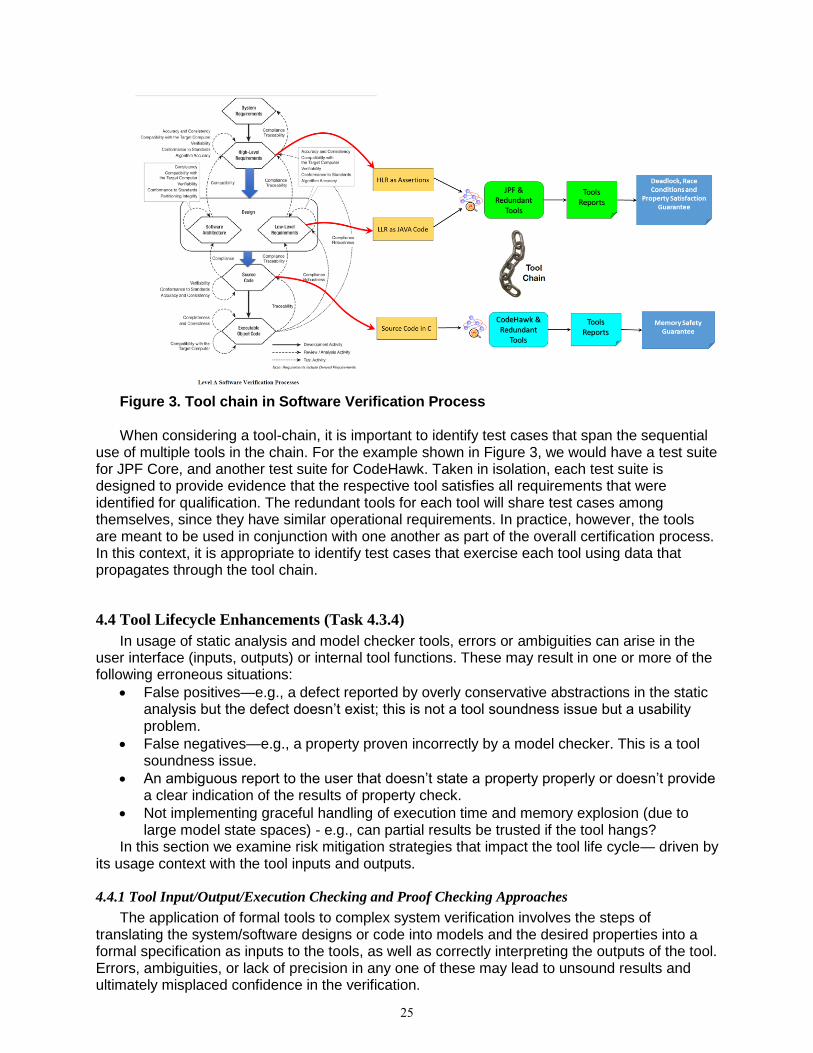
Figure 3. Tool chain in Software Verification Process When considering a tool-chain, it is important to identify test cases that span the sequential
use of multiple tools in the chain. For the example shown in Figure 3, we would have a test suite for JPF Core, and another test suite for CodeHawk. Taken in isolation, each test suite is designed to provide evidence that the respective tool satisfies all requirements that were identified for qualification. The redundant tools for each tool will share test cases among themselves, since they have similar operational requirements. In practice, however, the tools are meant to be used in conjunction with one another as part of the overall certification process. In this context, it is appropriate to identify test cases that exercise each tool using data that propagates through the tool chain.
4.4 Tool Lifecycle Enhancements (Task 4.3.4)
In usage of static analysis and model checker tools, errors or ambiguities can arise in the user interface (inputs, outputs) or internal tool functions. These may result in one or more of the following erroneous situations:
False positives—e.g., a defect reported by overly conservative abstractions in the static analysis but the defect doesn’t exist; this is not a tool soundness issue but a usability problem.
False negatives—e.g., a property proven incorrectly by a model checker. This is a tool soundness issue.
An ambiguous report to the user that doesn’t state a property properly or doesn’t provide a clear indication of the results of property check.
Not implementing graceful handling of execution time and memory explosion (due to large model state spaces) - e.g., can partial results be trusted if the tool hangs?
In this section we examine risk mitigation strategies that impact the tool life cycle— driven by its usage context with the tool inputs and outputs.
4.4.1 Tool Input/Output/Execution Checking and Proof Checking Approaches
The application of formal tools to complex system verification involves the steps of translating the system/software designs or code into models and the desired properties into a formal specification as inputs to the tools, as well as correctly interpreting the outputs of the tool. Errors, ambiguities, or lack of precision in any one of these may lead to unsound results and ultimately misplaced confidence in the verification.
25
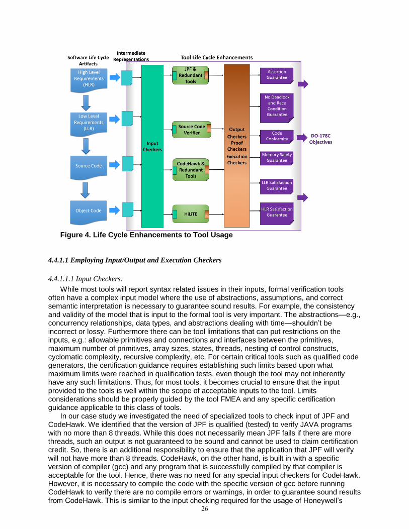
Figure 4. Life Cycle Enhancements to Tool Usage
4.4.1.1 Employing Input/Output and Execution Checkers
4.4.1.1.1 Input Checkers.
While most tools will report syntax related issues in their inputs, formal verification tools often have a complex input model where the use of abstractions, assumptions, and correct semantic interpretation is necessary to guarantee sound results. For example, the consistency and validity of the model that is input to the formal tool is very important. The abstractions—e.g., concurrency relationships, data types, and abstractions dealing with time—shouldn’t be incorrect or lossy. Furthermore there can be tool limitations that can put restrictions on the inputs, e.g.: allowable primitives and connections and interfaces between the primitives, maximum number of primitives, array sizes, states, threads, nesting of control constructs, cyclomatic complexity, recursive complexity, etc. For certain critical tools such as qualified code generators, the certification guidance requires establishing such limits based upon what maximum limits were reached in qualification tests, even though the tool may not inherently have any such limitations. Thus, for most tools, it becomes crucial to ensure that the input provided to the tools is well within the scope of acceptable inputs to the tool. Limits considerations should be properly guided by the tool FMEA and any specific certification guidance applicable to this class of tools.
In our case study we investigated the need of specialized tools to check input of JPF and CodeHawk. We identified that the version of JPF is qualified (tested) to verify JAVA programs with no more than 8 threads. While this does not necessarily mean JPF fails if there are more threads, such an output is not guaranteed to be sound and cannot be used to claim certification credit. So, there is an additional responsibility to ensure that the application that JPF will verify will not have more than 8 threads. CodeHawk, on the other hand, is built in with a specific version of compiler (gcc) and any program that is successfully compiled by that compiler is acceptable for the tool. Hence, there was no need for any special input checkers for CodeHawk. However, it is necessary to compile the code with the specific version of gcc before running CodeHawk to verify there are no compile errors or warnings, in order to guarantee sound results from CodeHawk. This is similar to the input checking required for the usage of Honeywell’s
26
HiLiTE tool—the input Simulink model must be simulatable and must pass a model compliance check to check limits on allowed primitives and parameters.
4.4.1.1.2 Output Checkers
Another class of checking tools, that we call output checkers, can be used to check for certain properties in outputs of verification tools. Model checkers such as JPF return counterexamples to illustrate how a property was falsified. In many cases many spurious and trivial counter examples will be returned that results in spending enormous amount of time to avoid them. Alternatively, one could implement tools that check the validity of counterexamples so that obviously false conjectures are eliminated. However, when the model checker does satisfy the specification it does simply return a positive but Boolean answer. While the positive answer does guarantee that property is satisfied, it may have been satisfied in an unintended fashion. For instance, if one indented to check a property that the system issued an acknowledgment whenever a request was sensed, the property will be trivially satisfied if there was never a request to the system due to an incorrect assumption. This is called vacuity and it many cases it has been found that detecting vacuities have uncovered unintended specifications and system behaviors [9]. One can implement such a vacuity checker in a model-checking tool.
In other cases, specialized checkers that parse the tool logs in addition to the actual result from the tool can report if the output is trustworthy from a specific perspective. For in- stance, JPF searches the application state space until a specified depth and reports property violations and satisfactions within that depth. However, if the depth of the software under test is more than the set depth, there is a possibility that JPF does not report the error found beyond the set depth. To avoid this problem, one could implement a special checkers that can parse JPF logs to identify if there were such unexplored paths and report the result appropriately. Other approaches, such as proof checkers, to check more complex/comprehensive aspects of a property proof are described in the next subsection.
4.4.1.1.3 Tool Execution Checks
An important criterion for all tools is to provide a set of complete and accurate results, with clear indication in the results if some error was detected by the incomplete tool execution that would compromise the soundness of the results. For example, in our case studies, we determined that there is the need to assure CodeHawk’s component scripts are executed properly. In the old CodeHawk implementation, the user invoking each CodeHawk component separately put the burden on the user to ensure the consistency between these component runs. The CodeHawk implementation was actually modified as part of the case study to mitigate this type of error—there is a master script now that runs the individual components.
Another important consideration for formal methods tools is to provide graceful handling of execution time and memory explosion (due to large model state spaces). This requires that the results should clearly indicate that tool execution is erroneous - thus invalidating all results. From the usability perspective, however, it may be practically necessary to identify validity of partial results (e.g., individual properties correctly proven). Our experience of using HiLiTE and model checkers suggests that such tools should implement stages of execution (e.g., one property proven in one stage) and return a successful exit code to the calling script if the tool terminates normally. A method should be provided, as permitted by the operating system, to terminate the tool in case of unacceptable execution time or memory usage that records in the overall execution results that the tool did not terminate normally.
In our case studies, both CodeHawk and JPF did not include any input/output checkers. In our failure mode analysis of these tools, we found that the risk of soundness issues by incorrect inputs and outputs of the tools were high and hence, one of our proposed mitigation strategies is to consider using relevant checkers outside the tool. These companion tool sets will help ensure that inputs and outputs not within the bounds of the designed limitations and required behavior of the verification or analysis tool.
27
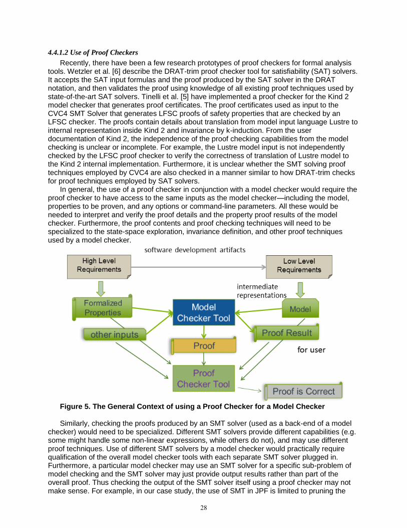
4.4.1.2 Use of Proof Checkers
Recently, there have been a few research prototypes of proof checkers for formal analysis tools. Wetzler et al. [6] describe the DRAT-trim proof checker tool for satisfiability (SAT) solvers. It accepts the SAT input formulas and the proof produced by the SAT solver in the DRAT notation, and then validates the proof using knowledge of all existing proof techniques used by state-of-the-art SAT solvers. Tinelli et al. [5] have implemented a proof checker for the Kind 2 model checker that generates proof certificates. The proof certificates used as input to the CVC4 SMT Solver that generates LFSC proofs of safety properties that are checked by an LFSC checker. The proofs contain details about translation from model input language Lustre to internal representation inside Kind 2 and invariance by k-induction. From the user documentation of Kind 2, the independence of the proof checking capabilities from the model checking is unclear or incomplete. For example, the Lustre model input is not independently checked by the LFSC proof checker to verify the correctness of translation of Lustre model to the Kind 2 internal implementation. Furthermore, it is unclear whether the SMT solving proof techniques employed by CVC4 are also checked in a manner similar to how DRAT-trim checks for proof techniques employed by SAT solvers.
In general, the use of a proof checker in conjunction with a model checker would require the proof checker to have access to the same inputs as the model checker—including the model, properties to be proven, and any options or command-line parameters. All these would be needed to interpret and verify the proof details and the property proof results of the model checker. Furthermore, the proof contents and proof checking techniques will need to be specialized to the state-space exploration, invariance definition, and other proof techniques used by a model checker.
Figure 5. The General Context of using a Proof Checker for a Model Checker Similarly, checking the proofs produced by an SMT solver (used as a back-end of a model
checker) would need to be specialized. Different SMT solvers provide different capabilities (e.g. some might handle some non-linear expressions, while others do not), and may use different proof techniques. Use of different SMT solvers by a model checker would practically require qualification of the overall model checker tools with each separate SMT solver plugged in. Furthermore, a particular model checker may use an SMT solver for a specific sub-problem of model checking and the SMT solver may just provide output results rather than part of the overall proof. Thus checking the output of the SMT solver itself using a proof checker may not make sense. For example, in our case study, the use of SMT in JPF is limited to pruning the
28

state space during search, and as such is not normally part of the results of the model checker (JPF) itself.
Based upon our analysis of current proof checking techniques, they are not simple checker tools but rather either redundant (if overlapping domain) or complementary tools whose the selection would be based upon the model checker’s specific capabilities and proof techniques employed. The fundamental problem is that the proof checker would have to do the same analysis of the model and properties that the model checker would do and therefore the same complexity issues that foil model checkers would apply (e.g., space and time complexity). Thus the qualification of just the proof checker instead of the model checker may be as complex as qualifying the model checker directly and thus rendering it impractical. We recommend treating a proof checker the same as a redundant or dissimilar tool and apply the same considerations as described in Section [refer to relevant subsection] of this report.
4.4.2 Tool Life Cycle and Qualification Considerations
There are different way to introduce checkers in the verification life cycle: either building them internally in the tool set itself or developing them outside the scope of the tool for the purpose of verifying the software under certification. There are pros and cons in each approach.
When such checking is built into the tools, it makes it convenient to users since they do not have to deal with ensuring correctness of inputs and outputs. It eliminates the class of soundness issues due incorrect inputs and outputs for all tool users with the users having to employ another tool and track it in their certification process. However, this implies additional development, error reporting, testing and maintenance for the tool developers. In fact, it adds to the complexity of building the tool. Users may not have access to details of how inputs and outputs are checked, so any errors in the checker are difficult to detect. Furthermore, a built-in input/output checker may share common failure modes with the tool itself.
On the other hand, if the tool does not handle such checks, then it becomes the responsibility of the user to ensure that the inputs are good and the output is sound. But, if users implement such a checker, although it might be an overhead in terms of development and ensuring consistency with the tool, they have the flexibility to restrict the input/output checking to only those that are relevant for that application and could be efficiently done. This can be done independently from the verification task.
4.5 Safety Case Argument Templates (Task 4.3.5)
This subtask calls for applying safety analysis to address the interaction among tools and its impact on verification objectives, and the degree of confidence required in each verification result. This approach was to be based on the safety analysis used for avionics systems, where the goal of designing a system to operate safely is replaced by the goal of creating an integrated tool set that provides high confidence in the correctness of the overall verification results. We were tasked to use the CertWare safety case workbench to capture representative templates or patterns of such tool qualification arguments. The resulting argument patterns were to be usable by safety case authors when presented with a risk mitigation strategy.
The overall form of a safety case argument derived from the use of formal methods tools in the certification of avionics software is that the various tools in the tool chain verify that the resulting executable software does or does not have certain safety related properties. Since this argument relies on a high degree of confidence in the soundness of the formal methods tools verifying these properties, the safety case can be improved by additional arguments that account for possible soundness risks in the use of these tools. Following the suggested analogy above with the use of failure modes and effects analysis (FMEA) for assessing the effects of individual component failures on the overall system behavior, we have looked for the effects of ”soundness failures” in individual tools on the overall verification by the tool chain. And as with the FMEA exercise of recommending mitigation strategies for point-component failures, we
29
have enumerated strategies to mitigate the risks of point-tool ”soundness failures” on the final verification verdict.
We chose the safety case argument DSL, ”L”, from the CertWare II Safety Case Workbench for capturing ”templates or patterns” of these augmented arguments. L is an English-like dialect of a standard Answer Set Programming (ASP) language. Safety case arguments captured in L can be automatically translated to the standard ASP language and submitted to external ASP solvers for assessing the logical satisfiability and validity of the arguments. Because this is a formal logic language, we can capture ”patterns or templates” of argumentation as general rules over predicates with variables. More concrete specializations of these general predicates represent individual safety cases that conform to the overall argument structure.
We began by capturing the most general form of the (augmented) safety case argument with the following L rule:
invalidityRisk(certification(property P, software S)) if reliesOn(certification(P, S), evidence E) and produces(toolChain TC, E, P, S) and verificationRisk(risk R, P, S, TC) and not mitigated(R, P, S, TC). This says that there is a risk that the certification of any software S having any property P is
invalid if the certification relies on some evidence for S having P, produced by some tool chain, and there is a verification risk for this component of the tool chain that has not been mitigated.
This project has enumerated various kinds of these verification risks for formal methods (FM) tools, but for this subtask we concentrated on undetected soundness risks for individual tools. We formalized three of these risks, for the three classes of FM tools we have been considering, by refining the extension of the verificationRisk predicate into three clauses, one for each tool type. We refined the mitigated predicate above into four clauses covering mitigation strategies for
1) redundant static analyzers (similar-redundant) 2) redundant model checkers (similar-redundant) 3) verifying the same property with model checker and static analyzer
(dissimilar-redundant) 4) multiple back-end SMT solvers We then filled in enough of a scenario of ground facts about tools, tool-chains, and
verification claims so that inferences about risk and mitigation could be automatically tested for satisfiability. Actual runs of the AST solver demonstrated an initial scenario with soundness risks, and a later elimination of those risks due to the addition of mitigation strategies. The details can be found in section 5 of the Risk Mitigation Strategies Report [12].
30
References [1] Coverity - static code analysis. http://www.synopsys.com/software/coverity/. Accessed:
2016-09-09. [2] Symbolic PathFinder (SPF). http://babelfish.arc.nasa.gov/trac/jpf/wiki/projects/jpf-
symbc. Accessed: 2016-09-09. [3] Ssat datcpi (facts) theoretical soundness issues report. Technical Report submitted to
NASA under Contract NNL14AA07C, 2015. [4] Clark Barrett, Pascal Fontaine, and Cesare Tinelli. The Satisfiability Modulo Theories
Library (SMT-LIB). www.SMT-LIB.org, 2016. [5] Cesare Tinelli et al. Kind 2 user documentation, version v1.0.1. https://kind2-
mc.github.io/kind2/doc/user documentation.pdf, 2016. [6] Wetzler et al. Drat-trim: Efficient checking and trimming using expressive clausal proofs.
Volume 8561 of the series Lecture Notes in Computer Science pp 422-429, 2014. [7] Klaus Havelund and Thomas Pressburger. Model checking java programs using java
pathfinder. International Journal on Software Tools for Technology Transfer, 2(4):366– 381, 2000.
[8] Gerard J. Holzmann. The design and validation of computer protocols. 1991. [9] Orna Kupferman. Sanity checks in formal verification. In CONCUR 2006–Concurrency
Theory, pages 37–51. Springer, 2006. [10] Robert A Martin. Common weakness enumeration. Mitre Corporation, 2007. [11] Corina S Pa ̆s ̆areanu and Neha Rungta. Symbolic pathfinder: symbolic execution of
java bytecode. In Proceedings of the IEEE/ACM international conference on Automated Software Engineering, pages 179–180. ACM, 2010.
[12] Companion documents and case study artifacts produced under this contract. https://shemesh.larc.nasa.gov/fm/
31
REPORT DOCUMENTATION PAGE
Standard Form 298 (Rev. 8/98) Prescribed by ANSI Std. Z39.18
Form Approved OMB No. 0704-0188
The public reporting burden for this collection of information is estimated to average 1 hour per response, including the time for reviewing instructions, searching existing datasources, gathering and maintaining the data needed, and completing and reviewing the collection of information. Send comments regarding this burden estimate or any otheraspect of this collection of information, including suggestions for reducing the burden, to Department of Defense, Washington Headquarters Services, Directorate for InformationOperations and Reports (0704-0188), 1215 Jefferson Davis Highway, Suite 1204, Arlington, VA 22202-4302. Respondents should be aware that notwithstanding any otherprovision of law, no person shall be subject to any penalty for failing to comply with a collection of information if it does not display a currently valid OMB control number. PLEASE DO NOT RETURN YOUR FORM TO THE ABOVE ADDRESS.
1. REPORT DATE (DD-MM-YYYY) 2. REPORT TYPE 3. DATES COVERED (From - To)
4. TITLE AND SUBTITLE 5a. CONTRACT NUMBER
5b. GRANT NUMBER
5c. PROGRAM ELEMENT NUMBER
5d. PROJECT NUMBER
5e. TASK NUMBER
5f. WORK UNIT NUMBER
6. AUTHOR(S)
7. PERFORMING ORGANIZATION NAME(S) AND ADDRESS(ES) 8. PERFORMING ORGANIZATION REPORT NUMBER
10. SPONSOR/MONITOR'S ACRONYM(S)
11. SPONSOR/MONITOR'S REPORT NUMBER(S)
9. SPONSORING/MONITORING AGENCY NAME(S) AND ADDRESS(ES)
12. DISTRIBUTION/AVAILABILITY STATEMENT
13. SUPPLEMENTARY NOTES
14. ABSTRACT
15. SUBJECT TERMS
16. SECURITY CLASSIFICATION OF:
a. REPORT b. ABSTRACT c. THIS PAGE
17. LIMITATION OF ABSTRACT
18. NUMBER OF PAGES
19a. NAME OF RESPONSIBLE PERSON
19b. TELEPHONE NUMBER (Include area code)
(757) 864-9658
This is the Final Report of a research project to investigate issues and provide guidance for the qualification of formal methods tools under the DO-330 qualification process. It consisted of three major subtasks spread over two years: 1) an assessment of theoretical soundness issues that may affect qualification for three categories of formal methods tools, 2) a case study simulating the DO-330 qualification of two actual tool sets, and 3) an investigation of risk mitigation strategies that might be applied to chains of such formal methods tools in order to increase confidence in their certification of airborne software.
NASA Langley Research Center Hampton, VA 23681-2199
National Aeronautics and Space Administration Washington, DC 20546-0001
Unclassified - Unlimited Subject Category 64 Availability: NASA STI Program (757) 864-9658
NASA-CR-2017-219372
01- 02- 2017 Contractor Report
STI Help Desk (email: [email protected])
U U U UU
Assurance case; DO-330 qualification; Formal methods; Risk mitigation; Soundness
Formal Assurance Certifiable Tooling Strategy Final Report
Bush, Eric; Oglesby, David; Bhatt, Devesh; Murugesan, Anitha; Engstrom, Eric; Mueller, Joe; Pelican, Michael
999182.02.85.07.01
36
NASA
NNL14AA07C
Langley Technical Monitor: Benedetto L. Di Vito