formatdgt - bellecomfort.co.nz format dgt... · instruction booklet to the user. fonderie sime...
TRANSCRIPT

FORMAT DGT
Fonderie SIME S.p.A Cod. 6304368B - 03/2013
ES
PT
ENG


INSTALLER INSTRUCTIONS
CONTENTS
1 DESCRIPTION OF THE BOILER . . . . . . . . . . . . . . . . . . . . . . . . . . . . . . . . . . . . . . . . . . . . . . . . . . . . . . . . . . . . . . . pag. 64
2 INSTALLATION . . . . . . . . . . . . . . . . . . . . . . . . . . . . . . . . . . . . . . . . . . . . . . . . . . . . . . . . . . . . . . . . . . . . . . . . . . . . . . pag. 69
3 CHARACTERISTICS . . . . . . . . . . . . . . . . . . . . . . . . . . . . . . . . . . . . . . . . . . . . . . . . . . . . . . . . . . . . . . . . . . . . . . . . . pag. 80
4 USE AND MAINTENANCE . . . . . . . . . . . . . . . . . . . . . . . . . . . . . . . . . . . . . . . . . . . . . . . . . . . . . . . . . . . . . . . . . . . pag. 84
IMPORTANTWhen carrying out commissioning of the boiler, you are highly recommended to perform the following checks:
– Make sure that there are no liquids or inflammable materials in the immediate vicinity of the boiler.
– Make sure that the electrical connections have been made correctly and that the earth wire is connected to a
good earthing system.
– Open the gas tap and check the soundness of the connections, including that of the burner.
– Make sure that the boiler is set for operation for the type of gas supplied.
– Check that the flue pipe for the outlet of the products of the combustion is unobstructed and has been properly
installed.
– Make sure that any shutoff valves are open.
– Make sure that the system is charged with water and is thoroughly vented.
– Check that the circulating pump is not locked.
– Purge the system, bleeding off the air present in the gas pipe by operating the pressure relief valve on the gas
valve inlet.
– The installer must provide the user with instruction in operation of the boiler and safety devices and hand over the
instruction booklet to the user.
FONDERIE SIME S.p.A. of Via Garbo 27 - Legnago (VR) - Italy declares that its hot water boilers, which bear the
CE mark under European Directive 2009/142/CEE and are fitted with a safety thermostat calibrated to a maxi-
mum of 110°C, are not subject to application of PED Directive 97/23/CEE as they meet the requirements of arti-
cle 1 paragraph 3.6 of the Directive.
FO
RM
AT
DG
T - E
NG
LIS
H

1.2 DIMENSIONI
1.2.1 “25 OF” model (fig. 1)
D
Fig. 1
Fig. 1/a
1.2.2 “25 - 30 BF” models (fig. 1/a)
64
1.1 INTRODUCTION
“FORMAT DGT” are the gas fuelled burner
groups for heating and the production of
hot sanitary water, constructed to satisfy
the needs of collective residential housing
and modern plant.
They are apparatuses which conform to
the European directives 2009/142/CE,
2004/108/CE, 2006/95/CE and
92/42/CE.
The can be fuelled by natural gas (G20) or
LPG (G30-G31).
This booklet gives the instructions for the
following models:
– “FORMAT DGT 25 OF” open combustion
chamber with natural draw.
– “FORMAT DGT 25-30 BF” sealed com-
bustion chamber forced flow.
The instructions given in this manual are
provided to ensure proper installation and
perfect operation of the appliance.
1 DESCRIPTION OF THE BOILER
CONNECTIONS
R C.H. return
G 3/4” (UNI-ISO 228/1)
M C.H. flow
G 3/4” (UNI-ISO 228/1)
G Gas connection
G 3/4” (UNI-ISO 228/1)
E D.H.W. inlet
G 1/2” (UNI-ISO 228/1)
U D.H.W. outlet
G 1/2” (UNI-ISO 228/1)
DIMENSIONS 25 OF
D mm 130
CONNECTIONS
R C.H. return
G 3/4” (UNI-ISO 228/1)
M C.H. flow
G 3/4” (UNI-ISO 228/1)
G Gas connection
G 3/4” (UNI-ISO 228/1)
E D.H.W. inlet
G 1/2” (UNI-ISO 228/1)
U D.H.W. outlet
G 1/2” (UNI-ISO 228/1)
DIMENSIONS 25 BF 30 BF
L mm 400 450
K mm 203 221
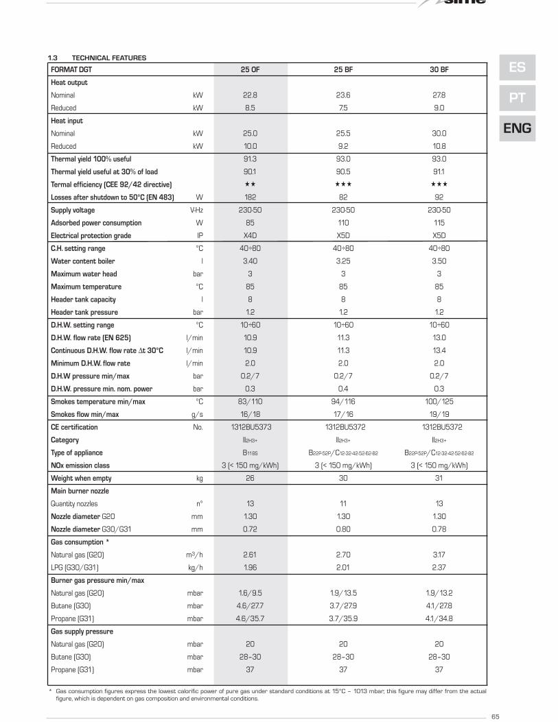
1.3 TECHNICAL FEATURES
65
ES
PT
ENG
* Gas consumption figures express the lowest calorific power of pure gas under standard conditions at 15°C – 1013 mbar; this figure may differ from the actual
figure, which is dependent on gas composition and environmental conditions.
FORMAT DGT 25 OF 25 BF 30 BF
Heat output
Nominal kW 22.8 23.6 27.8
Reduced kW 8.5 7.5 9.0
Heat input
Nominal kW 25.0 25.5 30.0
Reduced kW 10.0 9.2 10.8
Thermal yield 100% useful 91.3 93.0 93.0
Thermal yield useful at 30% of load 90.1 90.5 91.1
Termal efficiency (CEE 92/42 directive) «« ««« «««
Losses after shutdown to 50°C (EN 483) W 182 82 92
Supply voltage V-Hz 230-50 230-50 230-50
Adsorbed power consumption W 85 110 115
Electrical protection grade IP X4D X5D X5D
C.H. setting range °C 40÷80 40÷80 40÷80
Water content boiler l 3.40 3.25 3.50
Maximum water head bar 3 3 3
Maximum temperature °C 85 85 85
Header tank capacity l 8 8 8
Header tank pressure bar 1.2 1.2 1.2
D.H.W. setting range °C 10÷60 10÷60 10÷60
D.H.W. flow rate (EN 625) l/min 10.9 11.3 13.0
Continuous D.H.W. flow rate ∆t 30°C l/min 10.9 11.3 13.4
Minimum D.H.W. flow rate l/min 2.0 2.0 2.0
D.H.W pressure min/max bar 0.2/7 0.2/7 0.2/7
D.H.W. pressure min. nom. power bar 0.3 0.4 0.3
Smokes temperature min/max °C 83/110 94/116 100/125
Smokes flow min/max g/s 16/18 17/16 19/19
CE certification No. 1312BU5373 1312BU5372 1312BU5372
Category II2H3+ II2H3+ II2H3+
Type of appliance B11BS B22P-52P/C12-32-42-52-62-82 B22P-52P/C12-32-42-52-62-82
NOx emission class 3 (< 150 mg/kWh) 3 (< 150 mg/kWh) 3 (< 150 mg/kWh)
Weight when empty kg 26 30 31
Main burner nozzle
Quantity nozzles n° 13 11 13
Nozzle diameter G20 mm 1.30 1.30 1.30
Nozzle diameter G30/G31 mm 0.72 0.80 0.78
Gas consumption *
Natural gas (G20) m3/h 2.61 2.70 3.17
LPG (G30/G31) kg/h 1.96 2.01 2.37
Burner gas pressure min/max
Natural gas (G20) mbar 1.6/9.5 1.9/13.5 1.9/13.2
Butane (G30) mbar 4.6/27.7 3.7/27.9 4.1/27.8
Propane (G31) mbar 4.6/35.7 3.7/35.9 4.1/34.8
Gas supply pressure
Natural gas (G20) mbar 20 20 20
Butane (G30) mbar 28–30 28–30 28–30
Propane (G31) mbar 37 37 37
66
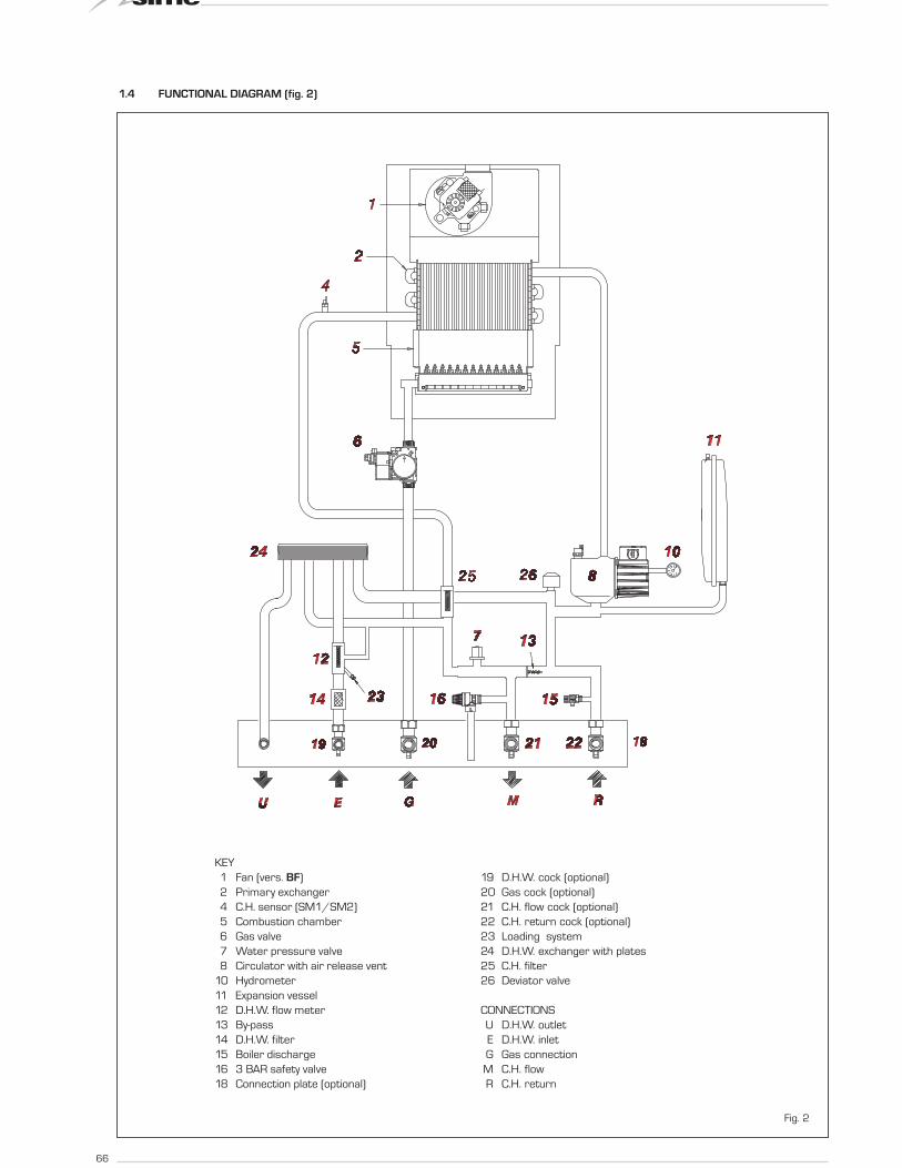
1.4 FUNCTIONAL DIAGRAM (fig. 2)
Fig. 2
KEY
1 Fan (vers. BF)
2 Primary exchanger
4 C.H. sensor (SM1/SM2)
5 Combustion chamber
6 Gas valve
7 Water pressure valve
8 Circulator with air release vent
10 Hydrometer
11 Expansion vessel
12 D.H.W. flow meter
13 By-pass
14 D.H.W. filter
15 Boiler discharge
16 3 BAR safety valve
18 Connection plate (optional)
19 D.H.W. cock (optional)
20 Gas cock (optional)
21 C.H. flow cock (optional)
22 C.H. return cock (optional)
23 Loading system
24 D.H.W. exchanger with plates
25 C.H. filter
26 Deviator valve
CONNECTIONS
U D.H.W. outlet
E D.H.W. inlet
G Gas connection
M C.H. flow
R C.H. return
67
ES
PT
ENG
6
7 8
5
9
4
3
2
1
11
10
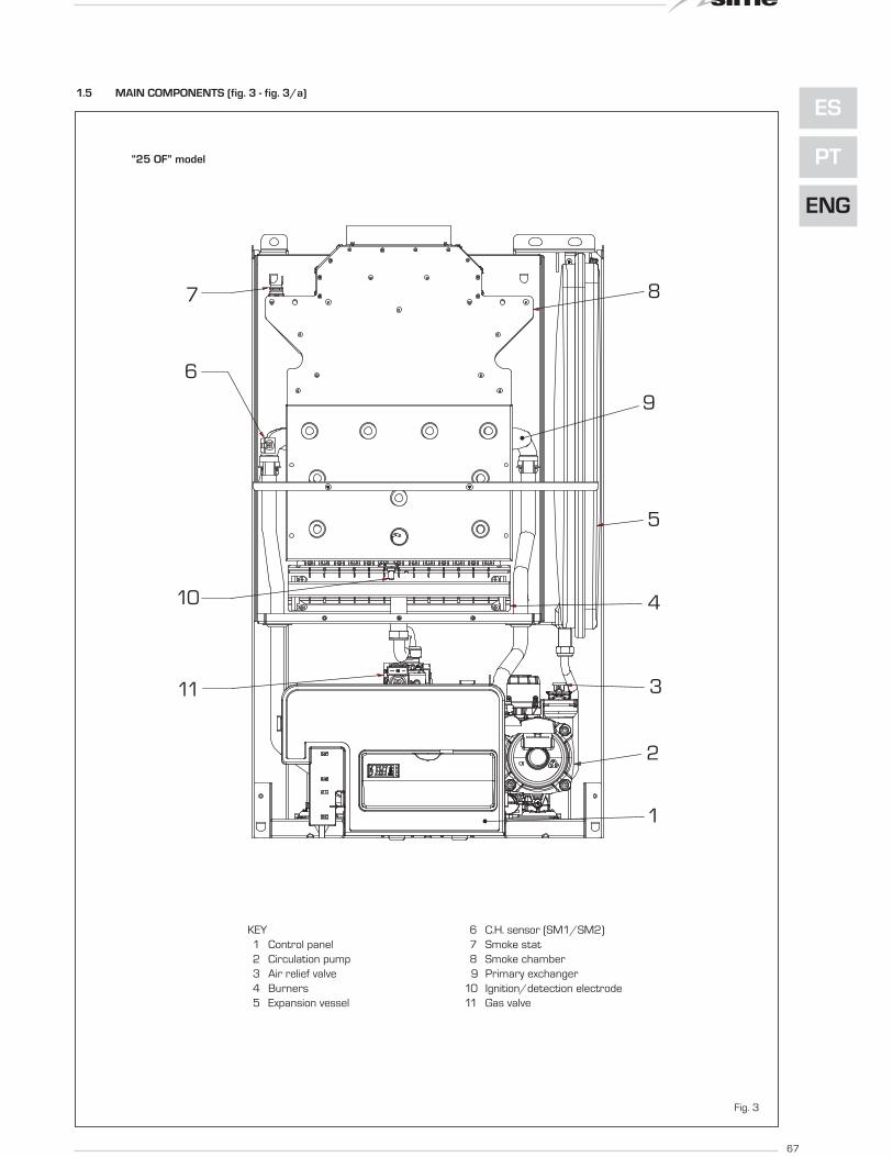
1.5 MAIN COMPONENTS (fig. 3 - fig. 3/a)
Fig. 3
“25 OF” model
KEY
1 Control panel
2 Circulation pump
3 Air relief valve
4 Burners
5 Expansion vessel
6 C.H. sensor (SM1/SM2)
7 Smoke stat
8 Smoke chamber
9 Primary exchanger
10 Ignition/detection electrode
11 Gas valve

68
1
2
3
4
5
78
6
9
10
11
Fig. 3/a
“25 - 30 BF” models
KEY
1 Control panel
2 Circulation pump
3 Air relief valve
4 Burners
5 Expansion vessel
6 C.H. sensor (SM1/SM2)
7 Air pressure switch
8 Fan
9 Primary exchanger
10 Ignition/detection electrode
11 Gas valve
69
ES
PT
ENG
The boiler must be installed in a fixed loca-
tion and only by specialized and qualified
firms in compliance with all instructions con-
tained in this manual. Furthermore, the
installation must be in accordance with cur-
rent standards and regulations.
2.1 INSTALLATION
- In the rooms where “type B” boilers are
installed, the air required for correct
combustion of the gas consumed by the
appliance must be able to flow in. It is
therefore necessary to make openings
that cannot be blocked in the outer walls,
which must be at least 6 cm2 for every
kW of thermal capacity installed and
with, in any case, a minimum of 100
cm2.
- “Type C” appliances, with combustion
chamber and air supply sealed off from
the environment, can be installed in any
room in the house.
- “Type B and C” boilers are suitable for
functioning in a partially protected place,
as according to EN 297, with maximum
environmental temperature of 60°C and
minimum of -5°C. We recommend instal-
lation of these boilers under the protru-
ding slope of a roof, on a balcony, or in a
protected niche, always providing they
are not directly exposed to adverse
weather (rain, hail, snow). The boilers are
provided already equipped with anti-free-
ze functions.
2.1.1 Anti-freeze function
The boilers are equipped with anti-freeze
function which activates the pumps and the
burner when the temperature of the water
contained inside the appliance drops to
below value PAR 10. The anti-freeze function
is ensured, however, only if:
- the boiler is correctly connected to the
gas and electricity supply circuits;
- the boiler is constantly fed;
- the boiler ignition is not blocked;
- the essential components of the
boiler are all in working order
In these conditions the boiler is protected
against frost down to an environmental tem-
perature of -5°C.
ATTENTION: In the case of installation in a
place where the temperature drops below
0°C, the connection pipes must be protec-
ted.
2.2 COMPLEMENTARY
ACCESSORIES
To facilitate connecting the boiler to the
system, the following accessories can be
supplied on request, complete with instruc-
tions for assembly:
- Installation plate code 8075427
- Elbows and gas taps/sanitary water out-
put set code 8075418
- Taps kit code 8091806
- Polyphosphates doser kit code 81071700
- Kit of couplings for replacing wall-hung
boilers of other makes code 8093900
- Solar kit for the instantaneous code
8105101
- Protection connection kit “25 BF” code
8094520
- Protection connection kit “30 BF” code
8094521
2.3 CONNECTING UP SYSTEM
To protect the heat system from damaging
corrosion, incrustation or deposits, before
installation it is extremely important to clean
the system using suitable products such as,
for example, Sentinel X300 (new systems),
X400 and X800 (old systems) or Fernox
Cleaner F3.
Complete instructions are provided with the
products but, for further information, you
may directly contact SENTINEL PERFOR-
MANCE SOLUTIONS LTD or FERNOX COOK-
SON ELECTRONICS. For long-term protec-
tion agains corrosion and deposits, the use
of inhibitors such as Sentinel X100 or Fer-
nox Protector F1 is recommended after
cleaning the system. It is important to check
the concentration of the inhibitor after each
system modification and during maintenan-
ce following the manufacturer’s instructions
(specific tests are available at your dealer).
The safety valve drain must be connected to
a collection funnel to collect any discharge
during interventions. If the heating system is
on a higher floor than the boiler, install the
on/off taps supplied in kit optional on the
heating system delivery/return pipes.
WARNING: Failure to clean the heat
system or add an adequate inhibitor invali-
dates the device’s warranty.
Gas connections must be made in accor-
dance with current standards and regula-
tions.
When dimensioning gas pipes from the
meter to the module, both capacity volume
(consumption) in m3/h and gas density
must be taken into account.
The sections of the piping making up the
system must be such as to guarantee a sup-
ply of gas sufficient to cover the maximum
demand, limiting pressure loss between the
gas meter and any apparatus being used to
not greater than:
– 1.0 mbar for family II gases (natural gas);
– 2.0 mbar for family III gases (butane or
propane).
An adhesive data plate is sticked inside the
front panel; it contains all the technical data
identifying the boiler and the type of gas for
which the boiler is arranged.
2.3.1 Filter on the gas pipe
The gas valve is supplied ex factory with an
inlet filter, which, however, is not adequate to
entrap all the impurities in the gas or in gas
main pipes. To prevent malfunctioning of the
valve, or in certain cases even to cut out the
safety device with which the valve is equip-
ped, install an adequate filter on the gas pipe.
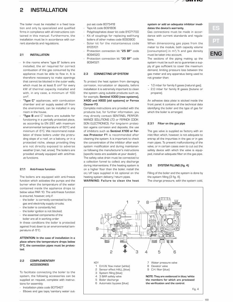
2.5 SYSTEM FILLING (fig. 4)
Filling of the boiler and the system is done by
the system filling (3 fig. 4).
The charge pressure, with the system cold,
2 INSTALLATION
Fig. 4
KEY
1 D.H.W. flow meter (white)
2 Sensor effect HALL (blue)
3 System filling (blue)
4 3 BAR safety valve
5 Boiler discharge
6 Automatic by-pass (blue)
7 Water pressure valve
8 Deviator valve
9 C.H. filter (blue)
NOTE: They are evidenced in blue/white
the members for which are previewed
the verification and the control.
32
1
4 5 6
7 8
9

70
must be between 1 and 1.2 bar.
Filling must be done slowly so as to allow
any air bubbles to be bled off through the air
valves.
Should the pressure have risen well above
the limit expected, discharge the over pres-
sure by opening the pressure-relief valve.
2.5.1 Emptying the system (fig. 4)
Use the drain tap to empty the system (5
fig. 4). Turn off the boiler before doing this.
2.6 FLUES/CHIMNEYS
A chimney or flue for the evacuation of the
combustion products into the atmosphere
must correspond to the requisites prescri-
bed by the laws in force.
In particular, the specific prescriptions of
law relative to boilers with natural draught
in collective pipes (type B) and those for boi-
lers with forced draught (type C) must be
respected.
2.6.1 Ducting of existing chimneys
To recover or duct existing chimneys, ducts
declared suitable for the purpose by the
manufacturer must be used, and the instal-
lation and use modalities indicated by the
said manufacturer must also be followed
as well as the prescriptions of Standard
UNI 10845.
2.7 INSTALLATION OF COAXIAL
DUCT (versions "BF")
2.7.1 Accessories 60/100 (fig. 5)
The 60/100 coaxial duct is supplied on
request in kit code 8084811.
The diagrams of f ig. 5 illustrate some
examples of different types of discharge
modalit ies al lowed and the maximum
lengths that can be reached.
2.7.2 Diaphragm for 60/100
coaxial duct (fig. 5/a)
The boiler is supplied with a diaphragm of
ø 79 (version 25 BF), ø 81 (version 30
BF).
Use the diaphragms according to the indi-
cations of fig. 5/a.
C12
C32
C42
3
1
2
7
64
3
2
8
x
y
max 5,0 m per vers. “20”max 3,5 m per vers. "25"max 3,0 m per vers. "30-35"
x + y = max 5,0 m per vers. "20"x + y = max 3,5 m per vers. "25"x + y = max 3,0 m per vers. "30-35"
min
1,3
m - m
ax
5 m
KEY
1 Coaxial flue kit L. 810 code 8084811
2 a Extension L. 1000 code 8096103
2 b Extension L. 500 code 8096102
3 Vertical extension L. 200 code 8086908
4 Additional 90° curve code 8095801
6 Articulated tile code 8091300
7 Roof outlet terminal L. 1284 code 8091200
8 Vertical condensation collector L. 200 code 8092803
Fig. 5
IMPORTANT:
– Each additional 90° curve
installed reduces the available
length by 1.0 metres.
– Each additional 45° curve
installed reduces the available
length by 0.50 metres.
- The insertion of the condensa-
tion collector (8) is obligatory
for vertical stretches of more
than 1.3 metres.
Fig. 5/a
For discharge types C12-C42, use the diaphragms supplied with the boiler:
- ø 79.0 for version “25” only when the length of the coaxial duct is less than 1 metre.
- ø 81.0 for version “30” only when the length of the coaxial duct is less than 1 metre.
For discharge types C32, use the following diaphragms according to the length of the duct and without
additional curves:
Installations with vertical Installations with vertical condensation
extension L. 200 code 8086908 * collector code 8092803 *
Models “25 BF - 30 BF” Models “25 BF - 30 BF”
Diaphragm Diaphragm Without Diaphragm Diaphragm Without
ø 79 ø 81 diaphragm ø 79 ø 81 diaphragm
L max = 2.5 m L max = 2.5 m L max = 5 m L max = 2.5 m L max = 2.5 m L max = 5 m
* Minimum length of duct L = 1.3 m.

71
ES
PT
ENG
2.7.3 Accessories ø 80/125
(fig. 6)
The ø 80 coaxial duct is supplied on reque-
st in a kit code 8084830 complete with
assembly instructions.
With the curve supplied in the kit, the maxi-
mum horizontal length of the duct must be
no more than 6 metres.
The diagrams in fig. 6 show some examples
of the different types of ø 80/125 coaxial
discharge modalities.
2.8 INSTALLATION OF SEPARATE
DUCTS (vers. “25-30 BF”)
When installing, the provisions of the laws
in force must be adhered to, as well as cer-
tain practical suggestions:
– With aspiration directly from outside,
when the duct is longer than 1 metre, it
is advisable to insulate the said duct in
order to avoid the formation of dew on
the outside of the pipe when the weather
is particularly cold.
– With ducts with discharge positioned
outside the building, or in cold environ-
ments, insulation is necessary to avoid
difficulty in starting the burner. In these
cases, a condensation system on the
pipes must be provided for.
– If the pipe passes through inflammable
walls, insulate the stretch of the fumes
discharge pipe that passes through the
C12
C32
C42
27
64
1
2min
. 4 m
- m
ax
7 m
8
x
y
x + y = min. 3,5 m/max 6 m "25"x + y = min. 3,0 m/max 6 m "30-35"
5
53 8
2
1
1
min. 3,5 m - max 6 m "25"
min. 3,0 m - max 6 m "30-35"
2
Fig. 6
KEY
1 Coaxial duct kit code 8084830
2 Extension L. 1000 code 8096130
3 Vertical extension L. 200 with coupling code 8086908
4a Additional 90° curve code 8095820
4b Additional 45° curve code 8095920
5 Adapter for 80/125 code 8093120
6 Tile for joint code 8091300
7 Terminal for roof exit L. 1284 code 8091200
8 Vertical condensation collector L. 200 code 8092803
IMPORTANT:
– Each additional 90° curve installed reduces the available length by 1.0 metres.
– Each additional 45° curve installed reduces the available length by 0.80 metres.
– The insertion of the condensation collector (8) is obligatory in C32 discharge type.
– The insertion of the condensation collector (8) is obligatory in C42 discharge type
when the stretch "y” is longer than 1.3 metres.
72
wall with rounded glass wool 30 mm
thick and with a density of 50 kg/m2.
The maximum total length, which is the
sum of lengths of the aspiration and
discharge pipes, is determined by the
loss of charge of the single accessories
inserted and must not result as more
than 9.0 mm H2O in version “25 BF” and
9.5 mm H2O in version “30 BF”.
For the loss of charge of the accessories,
refer to Table 1 and to the example given in
fig. 7.
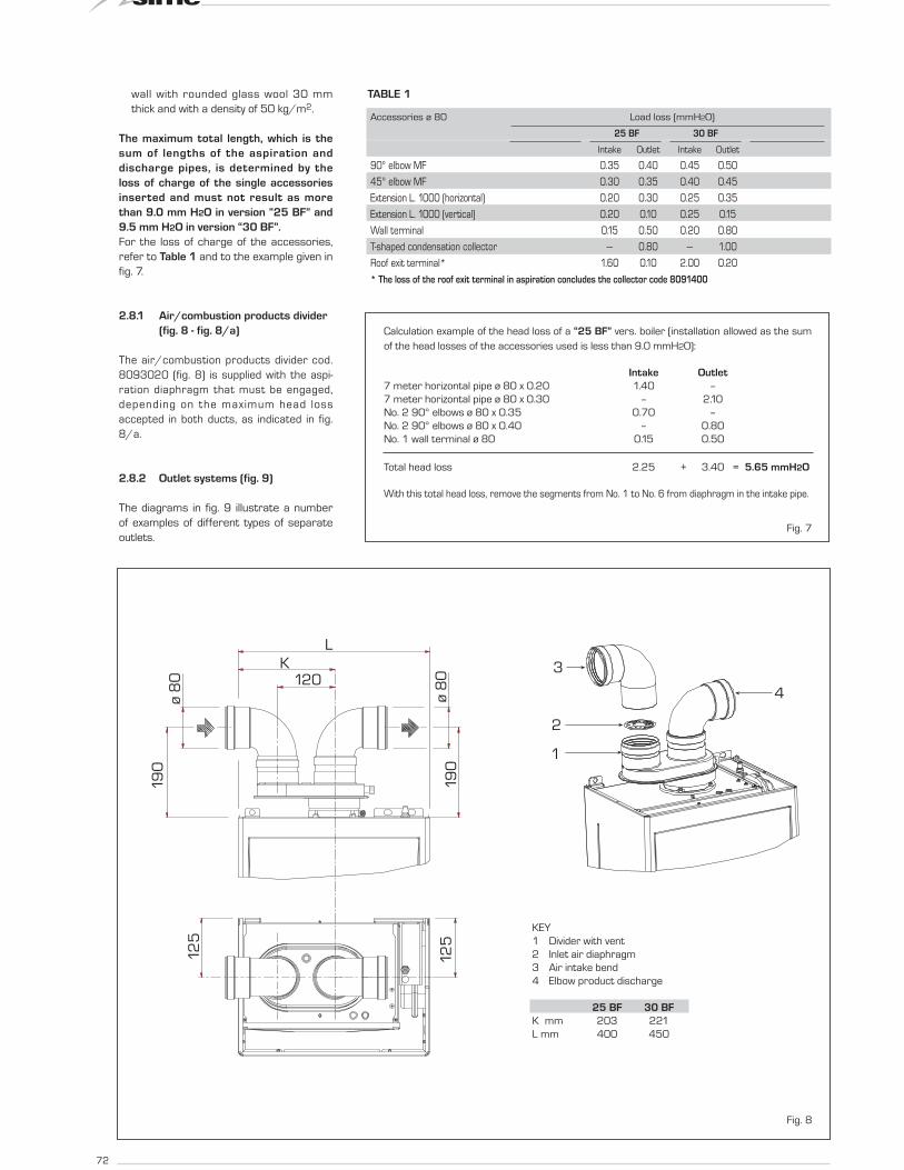
2.8.1 Air/combustion products divider
(fig. 8 - fig. 8/a)
The air/combustion products divider cod.
8093020 (fig. 8) is supplied with the aspi-
ration diaphragm that must be engaged,
depending on the maximum head loss
accepted in both ducts, as indicated in fig.
8/a.
2.8.2 Outlet systems (fig. 9)
The diagrams in fig. 9 illustrate a number
of examples of different types of separate
outlets.Fig. 7
Calculation example of the head loss of a “25 BF” vers. boiler (installation allowed as the sum
of the head losses of the accessories used is less than 9.0 mmH2O):
Intake Outlet
7 meter horizontal pipe ø 80 x 0.20 1.40 –
7 meter horizontal pipe ø 80 x 0.30 – 2.10
No. 2 90° elbows ø 80 x 0.35 0.70 –
No. 2 90° elbows ø 80 x 0.40 – 0.80
No. 1 wall terminal ø 80 0.15 0.50
Total head loss 2.25 + 3.40 = 5.65 mmH2O
With this total head loss, remove the segments from No. 1 to No. 6 from diaphragm in the intake pipe.
TABLE 1
Accessories ø 80 Load loss (mmH2O)
25 BF 30 BF
Intake Outlet Intake Outlet
90° elbow MF 0.35 0.40 0.45 0.50
45° elbow MF 0.30 0.35 0.40 0.45
Extension L. 1000 (horizontal) 0.20 0.30 0.25 0.35
Extension L. 1000 (vertical) 0.20 0.10 0.25 0.15
Wall terminal 0.15 0.50 0.20 0.80
T-shaped condensation collector --- 0.80 --- 1.00
Roof exit terminal* 1.60 0.10 2.00 0.20
* The loss of the roof exit terminal in aspiration concludes the collector code 8091400
1
2
3
4
L
K120
19
0
19
0
ø 8
0
ø 8
0
12
5
12
5
Fig. 8
KEY
1 Divider with vent
2 Inlet air diaphragm
3 Air intake bend
4 Elbow product discharge
25 BF 30 BF
K mm 203 221
L mm 400 450

73
ES
PT
ENG
2.9 FORCED EXHAUST
TYPE B22P-B52P (fig. 10)
Comply with the following requirements
during installation:
– Insulate the exhaust pipe and install a
condensation collection system at the
base of the vertical pipe.
– If the pipe passes through combustible
walls, insulate the section of the flue pipe
passing through the wall with a 30 mm
thick fibreglass pipe covering with a den-
sity of 50 kg/m3.
In “25-30 BF” models this type of exhaust
max 0,5 m
ma
x 0
,5 m
C12
B52
1
4
9
C52
B52
C32
C42
3
2
11
10
C82
B22
6
5
6
12
3
11
10
3
7
1
8
3
1
3
2
3
3 2
1
3
23 63
1
8 3
KEY
1 Air/combustion product divider code 8093020
2a 90° elbow MF (n° 6) code 8077410
2b 90° elbow MF with intake code 8077407
2c Isolated 90° elbows MF code 8077408
3a Extension L. 1000 (n° 6) code 8077309
3b Insulated extension L. 1000 code 8077306
3c Extension L. 500 (n° 6) code 8077308
3d Extension L. 135 with intake code 8077304
4 Outlet terminal code 8089501
5 Int.-est. ring kit code 8091500
6 Intake terminal code 8089500
7 45° elbow MF (n° 6) code 8077411
8 Condensation outlet L. 135 code 8092800
9 Doubler fitting code 8091400
10 Tile with articulated joint code 8091300
11 Roof outlet terminal L. 1390 code 8091201
12 Tee condensation outlet code 8093300
Fig. 9IMPORTANT: In type C52 the outlet and inlet flues must not come out on opposite walls.
CONFIGURATION C62: discharge and aspiration is by means of pipes available on sale and certified separately (the pressure loss in the
ducts must be calculated according to the Standard UNI EN 13384)
Fig. 8/a
No. segments Total load loss mm H2O
to remove 30 BF 25 BF
none 0 ÷ 0.8 0 ÷ 2.0
No. 1 0.8 ÷ 1.5 2.0 ÷ 3.0
No. 1 e 2 1.5 ÷ 2.4 3.0 ÷ 4.0
from No. 1 to 3 2.4 ÷ 3.2 -
from No. 1 to 4 3.2 ÷ 4.0 4.0 ÷ 5.0
from No. 1 to 5 4.0 ÷ 4.8 -
from No. 1 to 6 4.8 ÷ 5.6 5.0 ÷ 6.0
from No. 1 to 7 5.6 ÷ 6.5 6.0 ÷ 7.0
from No. 1 to 8 6.5 ÷ 7.3 -
from No. 1 to 9 7.3 ÷ 7.8 7.0 ÷ 8.0
from No. 1 to 10 7.8 ÷ 8.4 -
without diaphragm 8.4 ÷ 9.5 8.0 ÷ 9.0

74
pipe is installed using the special kit, code
8093020. For kit assembly instructions,
refer to point 2.8.1.
Protect the intake with the optional acces-
sory, code 8089501 (fig. 10). The air/com-
bustion product divider code 8093020 is
supplied with aspiration diaphragm that
must be engaged, depending on the maxi-
mum head loss allowed, as indicated in fig.
8/a.
Maximum flow resistance must be no
more than 9.0 mm H2O in vers. “25 BF” -
9.5 mm H2O in vers. “30 BF”.
As the maximum pipe length is determined
by adding up the flow resistance of the
various individual accessories installed,
refer to Table 1 for calculation.
2.10 POSITIONING OF OUTLET
TERMINALS (fig. 11)
The outlet terminals for forced draught
systems may be located on the outer walls
of the building Table 2 shows approximate,
non-binding minimum distances to be met
for a building of the type shown in fig. 11.
1) Terminals below a practicable balcony must be located in such a
way that the total path of the smoke from its outlet point from
the terminal to its outlet point from the external perimeter of the
balcony, including the height of possible railings, is not less than
2000 mm.
2) When siting terminals, where materials that may be subject
to the action of the combustion products are present in the
vicinity, e.g., eaves, gutters and downspouts painted or made
of plastic material, projecting timberwork, etc., distances of
not less than 1500 mm must be adopted, unless adequate
shielding is provided to guard these materials.
Fig. 11
Cod. 8089501
Fig. 10
TABLE 2
Siting of terminal Appliances from 7 to 35 kW
(distances in mm)
A - below openable window 600
B - below ventilation opening 600
C - below eaves 300
D - below balcony (1) 300
E - from adjacent window 400
F - from adjacent ventilation opening 600
G - from horizontal or vertical soil or drain pipes (2) 300
H - from corner of building 300
I - from recess in building 300
L - from ground level or other treadable surface 2500
M - between two terminals set vertically 1500
N - between two terminals set horizontally 1000
O - from a surface facing without
openings or terminals 2000
P - as above but with openings and terminals 3000

75
ES
PT
ENG
2.11 ELECTRICAL WIRING
If you must replace the electric power
cable supplied with the boiler, order it exclu-
sively from Sime.
The power supply must be single-phase
230V - 50 Hz through a main switch pro-
tected by a fuse with a distance of at least
3 mm between contacts.
NOTE: The boiler must be connected with
an efficient grounding system. SIME shall
not be held liable for injury or damage
resulting from failure to ground the boi-
ler.
ATTENTION: Before every intervention on
the boiler, cut off the electricity supply by
means of the main switch of the system,
since even if the boiler is "OFF", the elec-
trical panel remains connected to the
electricity.
2.11.1 Chronothermostat
connection
Remove the boiler casing, tilt the control
panel and connect the chronothermostat
to the 6 pole terminal board as indicated in
the boiler electrical diagram (see para-
graph 2.12) after having removed the exi-
sting bridge.
The chronothermostat to be used must be
of a class conforming to the standard EN
60730.1 (clean electrical contact).
2.11.2 Remote control CR 63
connection (optionals)
The boiler is designed for connection to a
remote control unit CR 63 code 8092219
coupled to an optional expansion kit code
8092240.
The remote control unit allows for complete
remote control of the boiler, except release
of the boiler.
Whenn the connection has been made the
boiler display will show the following messa-
ge: Cr.
For installation and use of the remote con-
trol, follow the instructions in the package.
2.11.3 External sensor connection
(optional)
The boiler is designed for connection to an
external temperature sensor, supplied on
request (code 8094101), which can auto-
matically regulate the temperature value of
the boiler output according to the external
temperature.
For installation, follow the instruction in the
package. It is possible to make corrections
to the values read by the drill acting on the
PAR 4.
2.11.4 Use with different
electronic systems
Some examples are given below of boiler
systems combined with different electronic
systems. The electrical connections to the
boiler refer to the wording on the diagrams
(figs. 13-13/a). The zone valve control
starts at every demand for heating of the
remote control.
Description of the letters indicating the
components shown on the system dia-
grams from 1 to 6:
M System output
R System return
CR Remote control CR 63
SE External temperature sensor
TA 1-2 Zone room thermostat
VZ 1-2 Zone valve
RL 1-2 Zone relay
Sl Hydraulic separator
P 1-2 Zone pump
IP Floor system
EXP Expansion card
(code 6301430)
VM Thermostatic mixer valve
TSB Safety thermostat low
temperature
R M
SE
TA
CR
EXP
1 BASIC SYSTEM
SYSTEM WITH A DIRECT ZONE AND ROOM THERMOSTAT, OR WITH
A REMOTE CONTROL (Code 8092219), KIT EXPANSION REMOTE
CONTROL (Code 8092240) AND EXTERNAL SENSOR (Code
8094101)

76
TA
R MSE
TA1 TA2TA
P2
RL
SI
RL1 RL2
P1P
TA
R M
VZ VZ1
TA2
VZ2
TA1
CR
EXP
SE
2 BASIC SYSTEM
MULTI-ZONE SYSTEM WITH VALVE, ROOM THERMOSTAT AND EXTERNAL SENSOR (Code 8094101)
3 BASIC SYSTEM
MULTI-ZONE SYSTEM WITH PUMP, ROOM THERMOSTATS AND EXTERNAL SENSOR (Code 8094101)
4 BASIC SYSTEM
MULTI-ZONE SYSTEM WITH VALVE, ROOM THERMOSTATS, REMOTE CONTROL (Code 8092219), KIT EXPANSION REMO-
TE CONTROL (Code 8092240) AND EXTERNAL SENSOR (Code 8094101)
TA
R M
SE
TA
VZ
TA1
VZ1
TA2
VZ2
PARAMETERS SETTINGS
Set the opening time of the VZ zone
valve:
PAR 17 = SYSTEM PUMP
ACTIVATION DELAY

77
ES
PT
ENG
TA
SI
R M
TA1 TA2
P2
RL1 RL2
P1P
SE
CR
EXP
TA
R MSE
TA2
SI
RL2
P2
P1
VM
IP
CR
EXP
TSB
6 MIXER VALVE SYSTEM
SYSTEM WITH ONE DIRECTED ZONE, AND ONE MIXER ZONE
5 BASIC SYSTEM
MULTI-ZONE SYSTEM WITH PUMPS, ROOM THERMOSTATS, REMOTE CONTROL (Code 8092219), KIT EXPANSION REMOTE
CONTROL (Code 8092240) AND EXTERNAL SENSOR (Code 8094101)
NOTE:
The heating is set from the
remote control for the first
zone and from the boiler panel
for the other zones.
If there is a request for heat at
the same time, the boiler is
activated at the highest tempe-
rature setting.
78
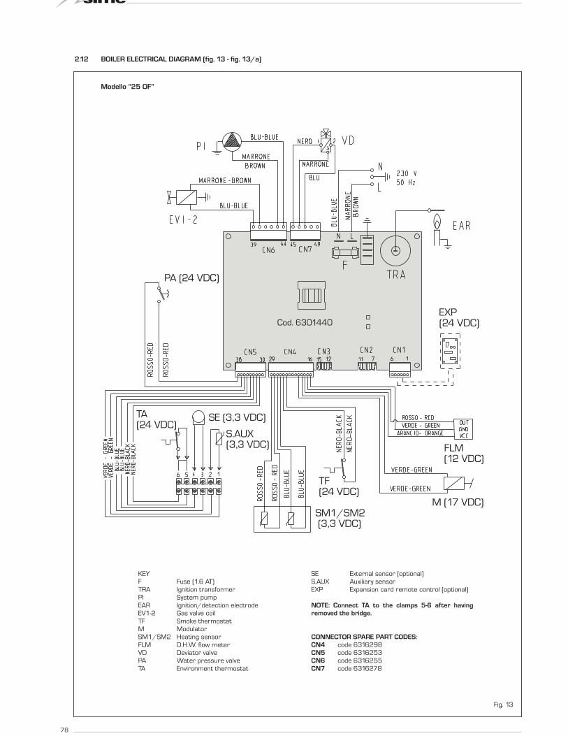
2.12 BOILER ELECTRICAL DIAGRAM (fig. 13 - fig. 13/a)
PA (24 VDC)
SM1/SM2 (3,3 VDC)
S.AUX(3,3 VDC)
SE (3,3 VDC)TA(24 VDC)
TF(24 VDC)
M (17 VDC)
FLM(12 VDC)
EXP(24 VDC)Cod. 6301440
Fig. 13
Modello “25 OF”
KEY
F Fuse (1.6 AT)
TRA Ignition transformer
PI System pump
EAR Ignition/detection electrode
EV1-2 Gas valve coil
TF Smoke thermostat
M Modulator
SM1/SM2 Heating sensor
FLM D.H.W. flow meter
VD Deviator valve
PA Water pressure valve
TA Environment thermostat
SE External sensor (optional)
S.AUX Auxiliary sensor
EXP Expansion card remote control (optional)
NOTE: Connect TA to the clamps 5-6 after having
removed the bridge.
CONNECTOR SPARE PART CODES:
CN4 code 6316298
CN5 code 6316253
CN6 code 6316255
CN7 code 6316278
79
ES
PT
ENG
SM1/SM2(3,3 VDC)
PF (24 VDC)
S.AUX(3,3 VDC)
SE (3,3 VDC)TA(24 VDC)
M (17 VDC)
FLM (12 VDC)
EXP (24 VDC)
PA (24 VDC)
Cod. 6301440
Fig. 13/a
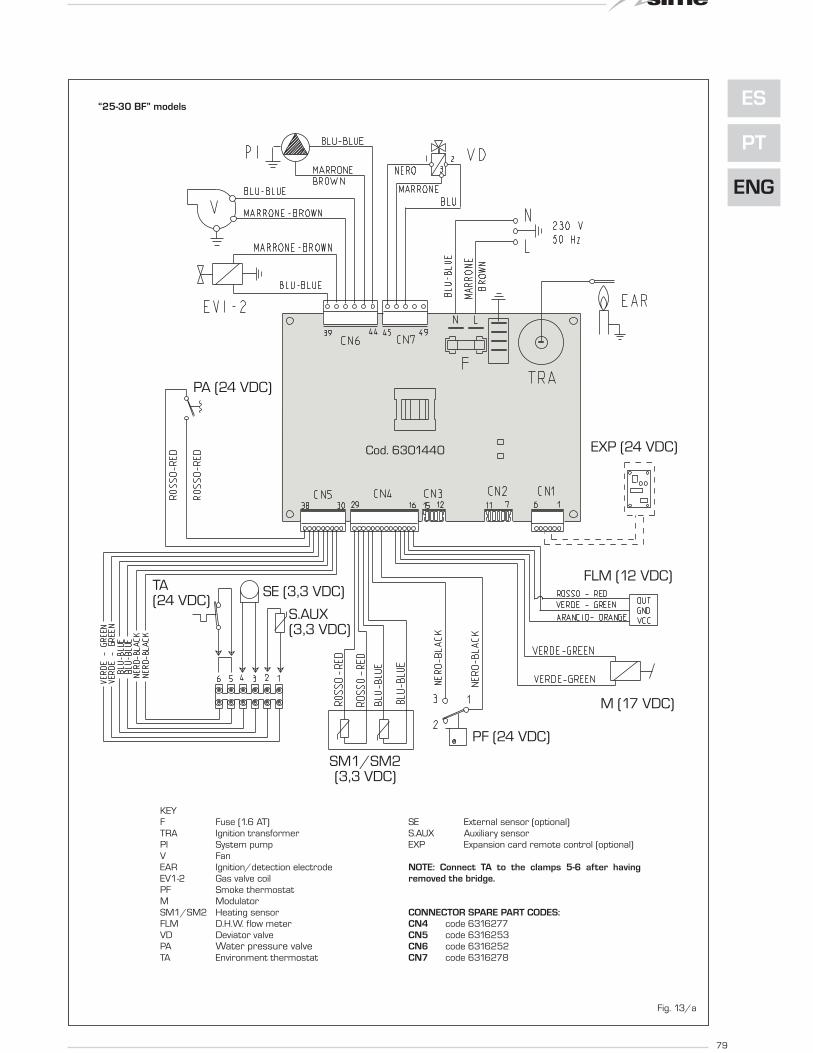
“25-30 BF” models
KEY
F Fuse (1.6 AT)
TRA Ignition transformer
PI System pump
V Fan
EAR Ignition/detection electrode
EV1-2 Gas valve coil
PF Smoke thermostat
M Modulator
SM1/SM2 Heating sensor
FLM D.H.W. flow meter
VD Deviator valve
PA Water pressure valveTA Environment thermostat
SE External sensor (optional)
S.AUX Auxiliary sensor
EXP Expansion card remote control (optional)
NOTE: Connect TA to the clamps 5-6 after having
removed the bridge.
CONNECTOR SPARE PART CODES:
CN4 code 6316277
CN5 code 6316253
CN6 code 6316252
CN7 code 6316278

80
3.1 CONTROL PANEL (fig. 14)
3 CHARACTERISTICS
1 23
4
1 - DESCRIPTION OF DISPLAY ICONS
SUMMER MODE ICON
WINTER MODE ICON
D.H.W. MODE ICON
HEATING MODE ICON
FUNCTIONING BURNER ICON
BLOCK DUE TO NO
IGNITION/FLAME DETECTION
NECESSITY OF RESET
MAIN DIGITS
Fig. 14
2 - DESCRIPTION OF CONTROLS
OPERATING MODE/RESET
By pressing the key in succession, pass to the sum-
mer and winter function (stand-by function if perma-
ne on the key more than two second).
RESET is only available if a resettable anomaly is
signalled
D.H.W. SET
Press the key to display the D.H.W. temperature
value set
HEATING SET
Press the key to display the heating temperature
value set (value not realtive to the remote control)
DECREASE
Pressing this key decreases the value set
INCREASE
Pressing this key increases the value set
3 - LED GREEN
ON = Indicates the presence of electrical voltage.
It switches of momentarily every time the keys are pressed.
It can be disabled by setting PAR 3 = 0.
4 - LED RED
OFF = Regular functioning.
ON = Boiler anomaly signalled.
Flashing when the control panel buttons are pressed inside the
PARAMETERS SECTION.

81
ES
PT
ENG
3.2 ACCESS TO INSTALLER'S
PARAMETERS
For access to the installer's parameters,
press simultaneously the keys of boiler
panel ( and ) for 5 seconds.
The red LED flashes and the display shows:
The parameters can be scrolled with
or .
To enter the parameter press or .
The value set flashes, the display shows:
Proceed as follows to change the set value:
- set the new value using or .
- confirm the set value using or .
Press to exit the parameters section.
The display is shown automatically after 5
minutes.
The parameters section contains the
alarms log, info and meters (display only).
3.2.1 Replacing the board or
RESETTING parameters
If the electronic board is replaced or reset,
it is necessary to configure PAR 01 and
PAR 02 by associating the following values
to each type of boiler to be able to restart
the boiler:
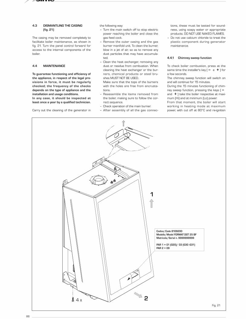
NOTE: the boiler panel has a label with
the values that have to be set for PAR 01
and PAR 02 (fig. 21).
BOILER GAS MODELS PAR 1
METHANE 25 01
BF (G20) 30 02
LPG 25 03
(G30/G31) 30 04
METHANE 25 05
OF (G20) 30 06
LPG 25 07
(G30/G31) 30 08
BOILER PAR 2
OF/BF 09
OF/BF 10
combined with sun-panel system
OF/BF 13
with automatic filling
OF/BF 14
combined with sun-panel system
and with automatic filling
PARAMETERS INSTALLERFAST CONFIGURATION
PAR DESCRIPTION RANGE UNIT OF INC/DEC DEFAULT
MEASUREMENT UNIT SETTING
01 Combustion configuration -- = ND = = “--”
1 ... 8
02 Hydraulic configuration -- = ND = = “--”
1 ... 22
03 Disabling of voltage presence LED 0 = Disabled = = 01
1 = Enabled
04 Correction of external probe values -5 ... 05 °C 1 00
05 Timer block of the keys -- = Disabled Min. 1 15
1 ... 99
D.H.W. - HEATING
PAR DESCRIPTION RANGE UNIT OF INC/DEC DEFAULT
MEASUREMENT UNIT SETTING
10 Boiler antifreeze 0 ... 10 °C 1 03
11 External sensor antifreeze -- = Disabled °C 1 - 2
- 9 ... 05
12 Climatic curve setting 03 ... 40 = 1 20
13 Minimum temperature heating 40 ... PAR 14 °C 1 40
14 Maximum temperature heating PAR 13 ... 80 °C 1 80
15 Maximum power heating 30 ... 99 % 1 99
16 Post-circulation time 0 ... 99 10 sec. 1 03
17 Pump heating activation delay 0 ... 99 10 sec. 1 01
18 Re-ignition delay 0 ... 10 Min. 1 03
19 Modulation D.H.W. flowmeter -- = Disabled = = 01
1 = Enabled
29 Anti-legionella (only D.H.W. tank) -- = Disabled °C 1 “--”
50 ... 80
PARAMETERS RE-SET
PAR DESCRIPTION RANGE UNIT OF INC/DEC DEFAULT
MEASUREMENT UNIT SETTING
49 * Reset default parameters -- , 1 = = =
(PAR 01 - PAR 02 equal “---”)
* If the current setting is difficult to understand or anomalous behaviour or if it is difficult to understandthe boiler, it is advised to restore the initial parameter values by setting PAR 49 = 1 and PAR 1 andPAR 2 as specified in point 3.2.1.
ALARMS (visualization)
PAR DESCRIPTION RANGE UNIT OF INC/DEC DEFAULT
MEASUREMENT UNIT SETTING
A0 Last code anomaly appearance = = = =
A1 Code anomaly previously appearance = = = =
A2 Code anomaly previously appearance = = = =
A3 Code anomaly previously appearance = = = =
A4 Code anomaly previously appearance = = = =
A5 Code anomaly previously appearance = = = =
A6 Code anomaly previously appearance = = = =
A7 Code anomaly previously appearance = = = =
A8 Code anomaly previously appearance = = = =
A9 Code anomaly previously appearance = = = =
INFO (visualization)
PAR DESCRIPTION RANGE UNIT OF INC/DEC DEFAULT
MEASUREMENT UNIT SETTING
i0 External sensor temperature -9 ... 99 °C 1 =
i1 C.H. 1 sensor temperature -9 ... 99 °C 1 =
i2 C.H. 2 sensor temperature -9 ... 99 °C 1 =
i3 D.H.W. sensor temperature -9 ... 99 °C 1 =
i4 Auxiliary sensor AUX temperature -9 ... 99 °C 1 =
i5 Set of effective heating temperature PAR 13 ... PAR 14 °C 1 =
i6 Level survey flame 00 ... 99 % 1 =
i7 Current to the modulator 00 ... 17 10 mA 1 =
i8 Flow rate D.H.W. flow meter 00 ... 99 l/min 1 =
COUNTERS (visualization)
PAR DESCRIPTION RANGE UNIT OF INC/DEC DEFAULT
MEASUREMENT UNIT SETTING
c0 Number hours of operation of the burner 00 ... 99 h x 100 0,1 from 0,0 to 9,9 00
1 from 10 to 99
c1 Number of ignitions of the burner 00 ... 99 x 1000 0,1 from 0,0 to 9,9 00
1 from 10 to 99
c2 Number total of the anomalies 00 ... 99 x 1 1 00
c3 Number approached the parameters installator 00 ... 99 x 1 1 00
c4 Number approached the parameters OEM 00 ... 99 x 1 1 00

82
3.4 EXTERNAL SENSOR (fig. 15)
If there is an external sensor, the heating
settings SET can be taken from the climatic
curves according to the external tempera-
ture and, in any case, limited to with the
range values described in point 3.2 (para-
meters PAR 13 and PAR 14).
The climatic curve to be set can be selected
from a value of 3 and 40 (at step 1).
Increasing the steepness of the curves of
fig. 15 will increase the output temperature
as the external temperature decreases.
3.5 CARD FUNCTIONING
The electronic card has the following func-
tions:
– Antifreeze protection of the heating cir-
cuit.
– Ignition and flame detection system.
– Control panel setting for the power and
the gas for boiler functioning.
– Anti-block for the pump which is fed for
a few seconds after 48 hours of inacti-
vity.
– Chimney sweep function which can be
activated from the control panel.
– Temperature which can be shifted with
the external sensor connected.
It can be set from the control panel.
– Automatic regulation of the ignition
power and maximum heating.
Adjustments are managed automati-
cally by the electronic card to guaran-
tee maximum flexibility in use of the
system.
– Interface with the following electronic
systems: remote control CR 73 o CR
63, with coupling kit card expansion
code 8092240.
3.6 TEMPERATURE
DETECTION SENSOR
Table 3 gives the values of the electrical
element (Ω) obtained on the heating sensor
according to the variations in temperature.
When the heating sensor (SM1/SM2) is
interrupted, the boiler will not function
for both services.
3.7 ELECTRONIC IGNITION
Ignition and flame detection is controlled by
a single electrode on the burner which gua-
rantees reaction in the case of accidental
extinction or lack of gas within one second.
3.7.1 Functioning cycle
Burner ignition occurs within max. 10
seconds after the opening of the gas valve.
Ignition failure with consequent activation of
block can be due to:
– Lack of gas
The ignition electrode persists in dischar-
ging for max. 10 seconds. If the burner
does not ignite, the anomaly is signalled.
This can happen the first time the boiler
is switched on after a long period of inac-
tivity due to the presence of air in the gas
pipes.
It can be caused by a closed gas tap or by
a broken valve coil (the interruption does
not allow for opening).
– The electrode does not discharge.
In the boiler, only the opening of the gas
to the burner can be detected. After 10
seconds the anomaly is signalled.
It can be caused by an interruption in the
electrode wire or if it is incorrectly ancho-
red to the connection points.
Or the electrode may be earthed or
strongly worn: it must be replaced.
Or the electronic card may be defective.
In the case of a sudden lack of voltage, the
burner will immediately switch off. When
voltage returns, the boiler will automatically
start up again.
3.8 FUMES THERMOSTAT
“25 OF”
This is a safety measure against the return
of the fumes into the environment due to
an inefficient or partially blocked chimney
(7 fig. 3).
It reacts by blocking the functioning of the
gas valve when the fumes are continually
forced back into the environment, in a
quantity that can be dangerous. If the boiler
repeatedly stops, it will be necessary to
carefully check the chimney, and to carry
out all modifications and take all measures
necessary to restore it to an ef f icient
working state. After every intervention car-
ried outon the device, check correct func-
tioning. In the case of replacement, use only
original spare parts.
3.9 FUMES PRESSURE SWITCH
“25-30 BF” (fig. 16)
The pressure switch is calibrated by the
manufacturer at the following values:
0.62 - 0.72 H2O for vers. “25 BF”
0.45 - 0.55 H2O for vers. “30 BF”,
which can guarantee boiler functioning also
TABLE 3
Temperature (°C) Resistance (Ω)
20 12.090
30 8.313
40 5.828
50 4.161
60 3.021
70 2.229
80 1.669
Fig. 15
ATTENTION: curves are calculated at an ambient temperature of
20°C. Using the key on the control panel, the user can change
the set ambient by ± 5°C for which the curve is calculated.
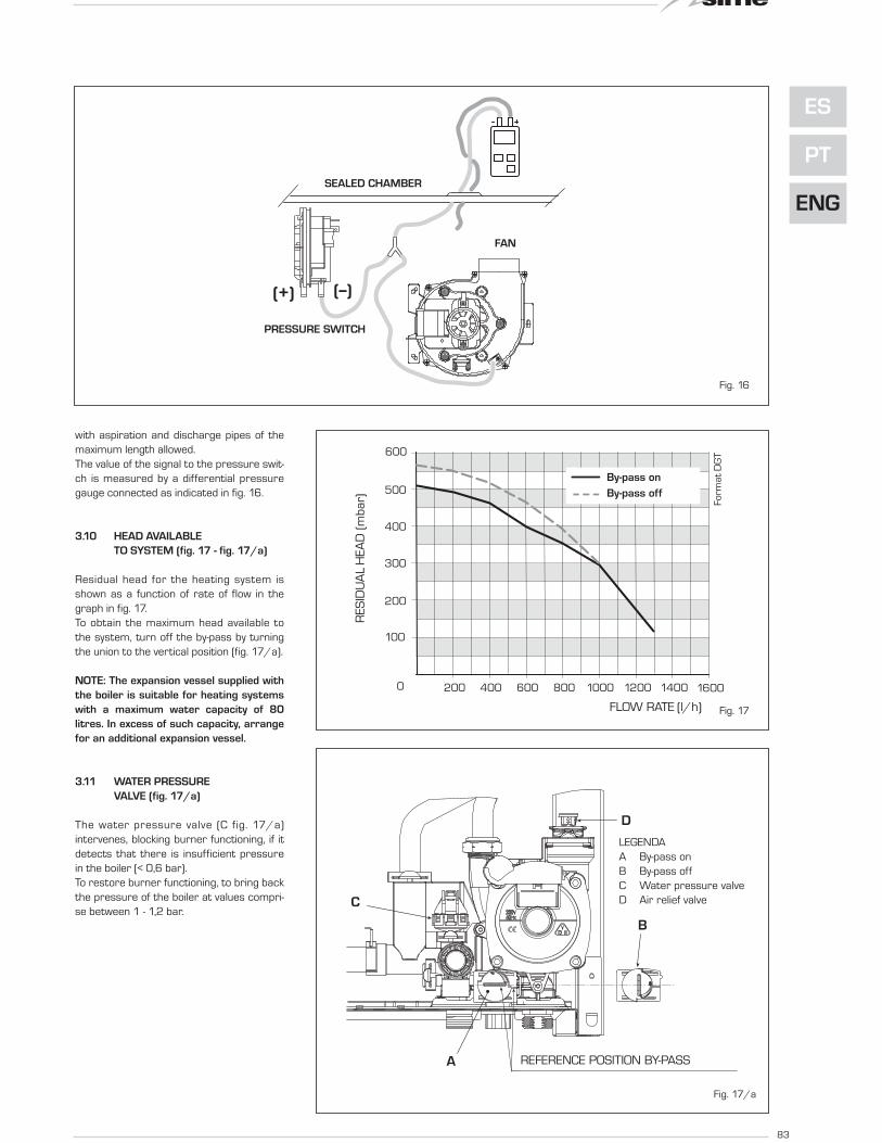
with aspiration and discharge pipes of the
maximum length allowed.
The value of the signal to the pressure swit-
ch is measured by a differential pressure
gauge connected as indicated in fig. 16.
3.10 HEAD AVAILABLE
TO SYSTEM (fig. 17 - fig. 17/a)
Residual head for the heating system is
shown as a function of rate of flow in the
graph in fig. 17.
To obtain the maximum head available to
the system, turn off the by-pass by turning
the union to the vertical position (fig. 17/a).
NOTE: The expansion vessel supplied with
the boiler is suitable for heating systems
with a maximum water capacity of 80
litres. In excess of such capacity, arrange
for an additional expansion vessel.
3.11 WATER PRESSURE
VALVE (fig. 17/a)
The water pressure valve (C fig. 17/a)
intervenes, blocking burner functioning, if it
detects that there is insufficient pressure
in the boiler (< 0,6 bar).
To restore burner functioning, to bring back
the pressure of the boiler at values compri-
se between 1 - 1,2 bar.
0 200 1600140012001000800600400
PORTATA (l/h)
PR
EVA
LEN
ZA
RES
IDU
A (
mb
ar)
500
400
100
200
300
Fo
rma
t D
GT600
By-pass inserito
By-pass escluso
83
ES
PT
ENG
RES
IDU
AL
HEA
D (
mb
ar)
FLOW RATE (l/h)
PRESSOSTATO
VENTILATORE
CAMERA STAGNA
(+) (--)
Fig. 16
Fig. 17
A
B
C
RIFERIMENTO POSIZIONE BY-PASS
D
Fig. 17/a
LEGENDA
A By-pass on
B By-pass off
C Water pressure valve
D Air relief valve
By-pass on
By-pass off
SEALED CHAMBER
FAN
PRESSURE SWITCH
REFERENCE POSITION BY-PASS

84
4.1 GAS VALVE (fig. 18)
The boilers are equipped standard with the
SIT 845 SIGMA gas valve (fig. 18).
The gas valve is set at two pressure values:
maximum and minimum.
According to the type of gas burnt, these
correspond to the values given in Table 4.
The gas pressures at the maximum and
minimum values, are factory set. Conse-
quently they must not be altered.
Only when you switch the appliance from
one type of gas supply (methane) to
another (butane or propane), it is permit-
ted to alter the operating pressure.
4.2 GAS CONVERSION (fig. 19)
This operation must be performed by
authorised personnel using original Sime
components.
To convert from natural gas to LPG or vice
versa, perform the following operations (fig.
19):
– Close the gas cock.
– Disassemble the burner manifold (3).
– Replace the main nozzles (6) supplied in
a kit, inserting the copper washer (4).
Use a ø 7 spanner to perform this ope-
ration.
– Configure the new fuel as indicated in
point 4.2.1
– For calibrating the maximum and mini-
mum gas pressure values, see point
4.2.2.
– After have ultimated the conversion of
the boiler, please stick onto the casing
panel the plate showing the relevant fee-
ding gas which is included into the kit.
NOTE: When reassembling components
which you have removed, replace gas
seals; test all gas connections after
assembly using soapy water or a product
made specifically for the purpose, being
sure not to use open flame.
4.2.1 New fuel configuration
Access the parameters section by pres-
sing the control panel keys ( and ) at
the same time for 5 seconds.
The red LED flashes and the display shows:
Scroll the parameters using or .
To enter the fuel configuration paramater
PAR 01, use or .
The set value flashes and if the boiler in
question is a 30 BF with methane, the
display shows:
4 USE AND MAINTENANCE
3
4
2
1
5
6
Fig. 19
KEY
1 Swivel connection 1/2”
2 Locknut 1/2”
3 Burner manifold
4 Washer ø 6.1
5 Burners
6 Nozzle M6
7 Screw
WARNING: To ensure a perfect
seal, always use the washer (4)
supplied in the kit when replacing
nozzles, even in burner units for
which it is not specified.
Fig. 18
KEY
1 Modulator
2 EV1-EV2 coils
3 Pressure inlet upstream
4 Pressure inlet downstream
5 VENT pressure
TABLE 4
Model Burner max pressure mbar Modulator current mA Burner min pressure mbar Modulator current mA
G20 (*) G30 G31 G20 (*) G30 G31 G20 (*) G30 G31 G20 (*) G30 G31
25 OF 9,1 27,7 35,7 130 165 165 1,6 4,6 4,6 0 0 0
25 BF 13,5 27,9 35,9 130 165 165 1,9 3,7 3,7 0 0 0
30 BF 13,2 26,8 34,8 130 165 165 1,9 4,1 4,1 0 0 0
(*) Max. burner pressure is guaranteed only when the supply pressure exceeds the max. burner pressure by at least 3 mbar.

85
ES
PT
ENG
For the 30 BF boiler to function with LPG,
press until 04 appears.
Confirm this value using or .
Exit the parameters section by pressing .
The table below gives the values to set
when the supply gas is changed:
4.2.2 Adjusting valve pressure (fig. 20)
Set maximum and minimum pressure on
gas valves as follows (fig. 20):
– Connect the column or a manometer to
the intake downstream of the gas valve.
In “25-30 BF” models, disconnect the
valve VENT pressure test point tube (5
fig. 18).
– Remove the cap (1) from the modulator.
– Press the keys ( and ) at the same
time for a few seconds and completely
open the hot sanitary water faucet.
– Press the key (Hi).
– Remember that rotating clockwise will
increase pressure while rotating anti-
clockwise will diminish it.
– Adjust maximum pressure using the nut
(3) with a wrench to the maximum pres-
sure value indicated in Table 4.
– Adjust the maximum pressure before
adjusting the minimum.
– Press the key (Lo) while the sanitary
water tap is on, with the water running.
– Lock the nut (3) in place, turn the
screw/nut (2) to the minimum pressu-
re indicated in Table 4.
– Press the keys ( and ) while kee-
ping the hot sanitary water running all
the time, and check that the maximum
and minimum pressures correspond to
the set values; if necessary correct the
regulation.
– Press the key again to quit the func-
tion.
– Put the pipe back on the valve VENT
pressure test point.
– Remove the manometer, remembering
to tighten the screw for closing the pres-
sure test point.
– Put the plastic cap (1) back on the modu-
lator and seal with a drop of coloured
sealant if necessary.
BOILER GAS MODELS PAR 1
METHANE 25 01
BF (G20) 30 02
LPG 25 03
(G30/G31) 30 04
METHANE 25 05
OF (G20) 30 06
LPG 25 07
(G30/G31) 30 08
3
2
1
Fig. 20
KEY
1 Plastic tap
2 Minimum pressure adjusting nut
3 Maximum pressure adjusting nut
86
4.3 DISMANTLING THE CASING
(fig. 21)
The casing may be removed completely to
facilitate boiler maintenance, as shown in
fig. 21. Turn the panel control forward for
access to the internal components of the
boiler.
4.4 MAINTENANCE
To guarantee functioning and efficiency of
the appliance, in respect of the legal pro-
visions in force, it must be regularly
checked; the frequency of the checks
depends on the type of appliance and the
installation and usage conditions.
In any case, it should be inspected at
least once a year by a qualified technician.
Carry out the cleaning of the generator in
the following way:
– Turn the main switch off to stop electric
power reaching the boiler and close the
gas feed cock.
– Remove the outer casing and the gas
burner manifold unit. To clean the burner,
blow in a jet of air, so as to remove any
dust particles that may have accumula-
ted.
– Clean the heat exchanger, removing any
dust or residue from combustion. When
cleaning the heat exchanger or the bur-
ners, chemical products or steel bru-
shes MUST NOT BE USED.
Make sure that the tops of the burners
with the holes are free from encrusta-
tions.
– Reassemble the items removed from
the boiler, making sure to follow the cor-
rect sequence.
– Check operation of the main burner.
– After assembly of all the gas connec-
tions, these must be tested for sound-
ness, using soapy water or appropriate
products. DO NOT USE NAKED FLAMES.
– Do not use calcium chloride to treat the
plastic component during generator
maintenance.
4.4.1 Chimney sweep function
To check boiler combustion, press at the
same time the installer's key ( e ) for
a few seconds.
The chimney sweep function will switch on
and will continue for 15 minutes.
During the 15 minutes functioning of chim-
ney sweep function, pressing the keys (
and ) take the boiler respective at maxi-
mum (Hi) and at minimum (Lo) power.
From that moment, the boiler will start
working in heating mode at maximum
power, with cut off at 80°C and re-ignition
1
24 xFig. 21
Codice/Code 8109200
Modello/Model FORMAT DGT 25 BF
Matricola/Serial n. 9999999999
PAR 1 = 01 (G20)/ 03 (G30 -G31)
PAR 2 = 09
87
ES
PT
ENG
at 70°C.
Before activating the chimney sweep func-
tion make sure that the radiator valves or
eventual zone valves are open.
The test can also be carried out with the
boiler working in D.H.W. mode.
For this, after activating the chimney sweep
function, open one or more hot water fau-
cets.
Under these conditions, the boiler will func-
tion at maximum power with the D.H.W.
kept at between 60°C and 50°C.
During the test, the hot water faucets
must remain open.
For exit to the chimney sweep function
press the key of the control panel.
The chimney sweep function will automa-
tically switch off after 15 minutes from
the activation.
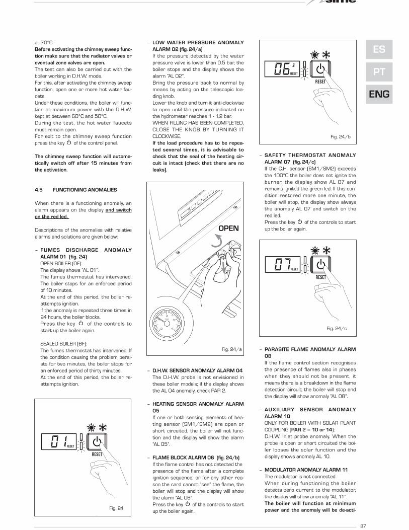
4.5 FUNCTIONING ANOMALIES
When there is a functioning anomaly, an
alarm appears on the display and switch
on the red led.
Descriptions of the anomalies with relative
alarms and solutions are given below:
– FUMES DISCHARGE ANOMALY
ALARM 01 (fig. 24)
OPEN BOILER (OF):
The display shows “AL 01”.
The fumes thermostat has intervened.
The boiler stops for an enforced period
of 10 minutes.
At the end of this period, the boiler re-
attempts ignition.
If the anomaly is repeated three times in
24 hours, the boiler blocks.
Press the key of the controls to
start up the boiler again.
SEALED BOILER (BF):
The fumes thermostat has intervened. If
the condition causing the problem persi-
sts for two minutes, the boiler stops for
an enforced period of thirty minutes.
At the end of this period, the boiler re-
attempts ignition.
– LOW WATER PRESSURE ANOMALY
ALARM 02 (fig. 24/a)
If the pressure detected by the water
pressure valve is lower than 0.5 bar, the
boiler stops and the display shows the
alarm “AL 02”.
Bring the pressure back to normal by
means by acting on the telescopic loa-
ding knob.
Lower the knob and turn it anti-clockwise
to open until the pressure indicated on
the hydrometer reaches 1 - 1.2 bar.
WHEN FILLING HAS BEEN COMPLETED,
CLOSE THE KNOB BY TURNING IT
CLOCKWISE.
If the load procedure has to be repea-
ted several times, it is advisable to
check that the seal of the heating cir-
cuit is intact (check that there are no
leaks).
– D.H.W. SENSOR ANOMALY ALARM 04
The D.H.W. probe is not envisioned in
these boiler models; if the display shows
the AL 04 anomaly, check PAR 2.
– HEATING SENSOR ANOMALY ALARM
05
If one or both sensing elements of hea-
ting sensor (SM1/SM2) are open or
short circuited, the boiler will not func-
tion and the display will show the alarm
“AL 05”.
– FLAME BLOCK ALARM 06 (fig. 24/b)
If the flame control has not detected the
presence of the flame after a complete
ignition sequence, or for any other rea-
son the card cannot “see” the flame, the
boiler will stop and the display will show
the alarm “AL 06”.
Press the key of the controls to start
up the boiler again.
– SAFETY THERMOSTAT ANOMALY
ALARM 07 (fig. 24/c)
If the C.H. sensor (SM1/SM2) exceeds
the 100°C the boiler does not ignite the
burner, the display show AL 07 and
remains ignited the green led. If this con-
dition restored more one minute, the
boiler will stop, the display show always
the anomaly AL 07 and switch on the
red led.
Press the key of the controls to start
up the boiler again.
– PARASITE FLAME ANOMALY ALARM
08
If the flame control section recognises
the presence of flames also in phases
when they should not be present, it
means there is a breakdown in the flame
detection circuit; the boiler will stop and
the display will show anomaly “AL 08”.
– AUXILIARY SENSOR ANOMALY
ALARM 10
ONLY FOR BOILER WITH SOLAR PLANT
COUPLING (PAR 2 = 10 or 14):
D.H.W. inlet probe anomaly. When the
probe is open or short circuited the boi-
ler looses the solar function and the
display shows anomaly AL 10.
– MODULATOR ANOMALY ALARM 11
The modulator is not connected.
When during functioning the boiler
detects zero current to the modulator,
the display will show anomaly “AL 11”.
The boiler will function at minimum
power and the anomaly will be de-acti-Fig. 24
Fig. 24/a
Apre
0 4
1 3
2bar
Fig. 24/b
Fig. 24/c
OPEN

88
vated when the modulator is reconnec-
ted or when the burner stops working.
– CONFIGURATION ANOMALY ALARM
12
Anomaly in the SEALED/OPEN configu-
ration. There may be a conflict between
the values set by the installer for PAR 1
and the self-detection carried out by the
card causes the activation of the alarm:
the boiler will not function and the display
will show anomaly “AL 12”.
Reset PAR 1 to de-activate the alarm or
check the pressure switch/combustion
product thermostat and relative connec-
tion.
– HEATING PROBE POSITIONING
ANOMALY SM1/SM2 “AL 16”
(fig. 24/d)
If the probe does not detect a tempera-
ture increase after burner ignition, the
burner switches off after 10 seconds,
the display shows anomaly AL 16 eand
the4 green LED stays on.
If the anomaly occurs three times within
24h lthe boiler blocks, the display conti-
nues to show anomaly AL 16 and the red
LED switches on.
Press on the control panel to re-start
the boiler.
– SENSOR ALIGNMENT ANOMALY “AL
17”
When the two sensitive elements of the
heating probe (SM1/SM2) dif fer to
each other by more than 16°C the boiler
does not function and the display shows
anomaly AL 17.
Reaplace the heat ing probe
(SM1/SM2) to restore functioning.
Fig. 24/d

USER INSTRUCTIONS
WARNINGS– In case of fault and/or incorrect equipment operation, deactivate it, without making any repairs or taking any direct action.
Apply only to qualified technical personnel.
– Boiler installation and any other assistance and/or maintenance activity must be carried out by qualified personnel per-
suant to Standard CEI 64-8. Under no circumstances, the devices sealed by the manufacturer can be tampered with.
– It is absolutely prohibited to block the intake grilles and the aeration opening of the room where the equipment is installed.
– The manufacturer shall not be held liable for any damage caused by improper use of the appliance.
– This appliance is not intended for use by persons (including children) with reduced physical, sensory or mental capabilities, or lack
of experience and knowledge, unless they have been given supervision or instruction concerning use of the appliance by a person
responsible for their safety. Children should be supervised to ensure that they do not play with the appliance.
LIGHTING AND OPERATION
BOILER IGNITION (fig. 25)
The first ignition of the boiler must be car-
ried out by qualified technical personnel.
Successively, if it is necessary to start up
the boiler again, adhere strictly to the fol-
lowing instructions: open the gas tap to
allow the flow of the fuel and move the main
switch of the system to “ON”. After a stop,
wait for about 30 seconds before restoring
functioning conditions do that the boiler can
perform the control sequence.
If the green led is on, this indicates the pre-
sence of voltage.
Keys lock
If the device is not used, the keys will be
locked 15 minutes after the last setting was
made (PAR 5 by default) and the display light
switches off.
To set one of the operating modes, press
any of the keys for more than two seconds
(the display will indicate one to four seg-
ments progressively before unlocking the
controls).
Winter
Press the key of the controls to activa-
te the winter mode functioning (heating and
D.H.W.). The display will be as shown in the
figure.
Summer
Press the key of the controls to activa-
te the summer mode functioning (only the
production D.H.W.). The display will be as
shown in the figure.
REGULATION OF THE WATER TEMPERA-
TURE FOR HEATING (fig. 26)
To set the temperature of the water for
89
ES
PT
ENG
Fig. 25
ATTENTION: for set up modality of function more adapted to graze the keys sim-
ply. One beep indicates that the boiler has taken command. If PAR 5 is disabled,
the display remains lit.

90
heating, press the key of the controls .
The display will be as shown in the figure.
Change the values with the key ( and
). Standard visualisation will return to
the display by pressing the key again, or
after 10 seconds if no key is pressed.
Regulation of the external
sensor (fig. 26/a)
If an external sensor is installed, the value
of the output temperature is automatically
chosen by the system, which quickly adjusts
the of flow temperature on the basis of the
external temperature.
If you wish to change the value of the tem-
perature, increasing or decreasing that cal-
culated automatically by the electronic
card, proceed as indicated in the preceding
paragraph.
The level of various correction of a value of
temperature proportional calculated. The
display will be as shown in fig. 26/a.
REGULATION OF THE D.H.W.
TEMPERATURE (fig. 27)
To set the desired temperature D.H.W.,
press the key of the controls.
The display will be as shown in the figure.
Change the values with the key ( and ).The display will return to the standard
visualisation by pressing the key again,
or after 10 seconds if no key is pressed.
TO SWITCH OFF THE BOILER (fig. 28)
In the case of a short absence, press more
than two second the key of the controls.
The display will be as shown in figure (boiler
in stand-by). In this way, leaving the electri-
city and the fuel supply connected, the boi-
ler is protected from frost and from the
pump becoming blocked.
If the boiler is not used for a prolonged
period, it is advisable to disconnect the
electricity supply, by switching off the main
switch of the system, and to close the gas
tap and, if low temperatures are expected,
to completely empty the hydraulic circuits
to avoid pipes being broken by the forma-
tion of ice in the pipes.
Fig. 26
Fig. 26/a
Fig. 28
Fig. 27

91
ES
PT
ENG
ANOMALIES AND SOLUTIONS
When there is a functioning anomaly, the
display controls shows and red led switch
on.
Descriptions of the anomalies with the rela-
tive alarms and solutions are given below:
– AL 01 (fig. 29)
Press the key of the controls to re-
start the boiler.
If the anomaly persists, request the
intervention of qualified technical per-
sonnel.
– AL 02 (fig. 29/a)
If the water pressure detected is lower
than 0.5 bar, the boiler will stop and the
display will show “AL 02”.
Bring the pressure back to normal by
means by acting on the telescopic type
loading knob.
Lower the knob and turn it anti-clockwise
to open until the pressure indicated by
the hydrometer is between 1 and 1.2
bars.
WHEN FILLING HAS BEEN COMPLETED
CLOSE THE KNOB TURNING IT
CLOCKWISE.
If it is necessary to repeat the system
loading procedure, it is advisable to
contact qualified technical personnel
to check the seal of the heating system
(to check whether there are any leaks).
– AL 04
Request assistance from qualified
technical personnel.
– AL 05
Request assistance from qualified
technical personnel.
– AL 06 (fig. 29/b)
Press the key of the controls to re-
start the boiler.
If the anomaly persists, request assi-
stance from qualified technical person-
nel.
– AL 07 (fig. 29/c)
Press the key of the controls to re-
start the boiler.
If the anomaly persists, request assi-
stance from qualified technical person-
nel.
– AL 08
Request assistance from qualified
technical personnel.
– AL 10
Request assistance from qualified
technical personnel.
– AL 11
Request assistance from qualified
technical personnel.
– AL 11
Request assistance from qualified
technical personnel.
– AL 12
Request assistance from qualified
technical personnel.
– AL 16 (fig. 29/d)
Press the key of the controls to re-
start the boiler.
If the anomaly persists, request assi-
stance from qualified technical person-
nel.
– AL 17
Request assistance from qualified
technical personnel.
GAS CONVERSION
If it is necessary to change to a different
type of gas, request assistance only from
authorised technical personnel.
MAINTENANCE
Annual maintenance of the appliance
should be planned sufficiently in advance,
requesting the assistance of authorised
technical personnel.
The boiler is supplied with an electric wire
for the electrical power supply which, in
the case of replacement, must be substi-
tuted only by another obtained from the
constructor.
Fig. 29
Fig. 29/a
Apre
0 4
1 3
2bar
OPEN
Fig. 29/b
Fig. 29/c
Fig. 29/d

Fonderie Sime S.p.A - Via Garbo, 27 - 37045 Legnago (Vr)
Tel. +39 0442 631111 - Fax +39 0442 631292 - www.sime.it
Do
cu
me
nta
tio
n D
pt.
Fo
nd
eri
e S
ime
S.p
.A.