foundation fieldbus has arrived and is here to stay · field bus case history intech •...
TRANSCRIPT

FIELD BUS CASE HISTORY
InTech • February 1998 CD
Foundation field bus hasarrived and is here to stayBy Jason M. Mangano andDan P. Dumdie
Interoperabilityamong multiplevendors is possible.
The first production installation of Founda-tion fieldbus (FF) demonstrating interoperabili-ty among multiple vendors with closed-loopcontrol distributed in the field started up onJune 3, 1997, at Daishowa America in PortAngeles, Washington. The installation includes afieldbus host and six fieldbus transmitters withtwo closed loops, six analog inputs, and five ana-log outputs. The installation controls a refinermill's inrerstage hydrogen peroxide bleachingprocess in a mechanical pulping facility. AI; anend user, Daishowa has developed a taste forwhat fieldbus can offer today as well as a flavorfor what's to come.
This article shares Daishowas experience overthe past 18 months with project engineering,start-up, and operating fieldbus instruments. Italso describeswhy fieldbus was chosen over othertechnologies, project benefits, training, mainte-nance, and opinions the mill has formed as aresult of doing the project. This iswritten for endusers interested in the technology and discussessome issues they may face as the new fieldbusinstrument revolution begins.
Technology drove selection processDaishowa chose to use a fieldbus instead of a
distributed control system (DCS) to explore newtechnology and save the mill some money. Withthe existing process area poorly automated andthe DCS cabinets full, this project was a primeapplication for new technology.
Daishowa selected FF over other digital alter-natives because it provides a comprehensive userlayer that is unprecedented in the industry. Froma technical perspective, the selection process wasstraightforward.
Ajunction box containing spur block (left) for easy connection. Jason ~Mangano (author) and Yee TakNgan show junction box that provides allbus power (right).
FIELOBUS CASE HISTORY
• February 1998 • InTech
Shell Hamburg uses Profibus-PA
By Peter Tomasik
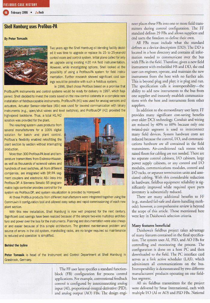
Two years ago the Shell Hamburg oil blending facility decid-ed it was time to upgrade or replace its 15- to 25-year-oldcontrol room and control system. Initial plans called for onlyan upgrade using existing 4-20 mA field instrumentation.However, while investigating options, Shell looked at thepossibility of using a Profibus-PA system for field instru-mentation. Further research showed significant cost sav-ings would be possible with such a fieldbus system.
In 1996, Shell chose Profibus based on a promise thatProfibus-PA instruments and control systems would be ready for delivery in 1997, which hap-pened. Shell decided to invest the costs saved on the new control cabinets in a complete newinstallation of fieldbus-capable instruments. Profibus-PA (H1) was used for analog sensors andactuators, Actuator Sensor-interface (AS-i) was used for low-end communication with binaryinstruments (e.g., open/shut valves and level switches), and Profibus-DP (H2) provided thehigh-speed backbone. Thus, a total H1/H2solution was provided for the plant.
The resulting system uses products fromseveral manufacturers for a 100% digitalsolution for batch and plant control.Profibus's flexibility enabled retrofitting theplant section by section without interruptingproduction.
More than 300 Profibus-PA level and tem-perature transmitters from Endress+Hauser,as well as thousands of solenoid valves andhundreds of level switches, all from differentcompanies, are integrated with DP/PA seg-ment couplers and electronic AS-i links intoProfibus-DP. A Siemens Simatic S5 program-mable logic controller provides control for thesystem via Profibus-DP, and system visualization is provided by Honeywell.
All these Profibus products from different manufacturers were integrated together using theCommuwin II configuration tool and allowed easy setup and rapid commissioning of each newplant section.
With this new installation, Shell Hamburg is now well prepared for the next century.Significant cost savings have been realized because of the simple two-wire multidrop architec-ture and power over the bus for the instruments. Planning and documentation were also cheap-er and easier because of this simple architecture. The greatest maintenance problem andsource of errors in the old system, marshalling racks, are no longer required so maintenanceis reduced and operation is simplified.
Behind the byline
Peter Tomasik is head of the Instrument and Control Department at Shell Hamburg inGrasbrook, Germany.
rnle FF user layerspecifiesa standard function-block I (FB) configuration for process controlapplications. For example, conventional feedbackcontrol is configured by interconnecting analoginput (Al), proportional-integral-derivative (PID),and analog output (AO) FBs. The design engi-
neer places these FBs into one or more field trans-mitters during control configuration. The FFstandard defines 29 FBs and allows suppliers andend users the freedom to define their own.
All FBs must include what the standarddefines as a device description (DD). The DD islocated in a host directory and contains all infor-mation needed to communicate over the buswith FBs in the field. Therefore, given a new fieldinstrument with embedded FB and DD, the enduser can engineer, operate, and maintain the newinstrument from the host with no further ado.This is beyond plug and play; it is plug and run.The specification calls it inreroperability-s-theability to add new instruments to the bus fromone supplier and instantly establish communica-tions with the host and instruments from othersuppliers.
In addition to the extraordinary user layer, FFprovides many significant cost-saving benefitsover older DCS technology. Conduit and wiringare reduced by 40% to 60% because only onetwisted-pair segment is used to interconnectmany field devices. System hardware costs arereduced because the control, I/O, and communi-cations hardware are all contained in the fieldtransmitters. Air-conditioned rack rooms withraised floors for cabling are not needed. There areno separate control cabinets, I/O cabinets, largepower supply cabinets, or any control and I/Omodules, communications modules, control andI/O racks, or separate termination units and asso-ciated cabling. With this considerable reductionin hardware, fieldbus equipment reliability is sig-nificantly improved while required spare partsinventory is substantially reduced.
There are many additional benefits to FF(e.g., standard fail-safeand alarm-handling meth-ods); however, a comprehensive review is beyondthe scope of this article. Those mentioned herewere key in Daishowas selection criteria.
Many features beneficialDaishowa's fieldbus project takes advantage
of many features contained in the final specifica-tion. The system usesAl, PID, and AO FBs forcontrolling and monitoring the process. Theconfiguration is done on a host PC and thendownloaded to the field. The PC interface cardserves as a link active scheduler (LAS), whichadministers all communications on the bus.Inreroperabiliry is demonstrated by two differentmanufacturers' products operating on one field-bus segment.
All six fieldbus transmitters for the projectwere delivered by Smar International, each withmultiple I/O (Al or AO) and PID FBs. National
FIElDBUS CASE HISTORY
InTech • February 1998 •
Instruments provided the host hardware and soft-ware. This included a fieldbus configuraror, theiroperator interface (Lookout), utility software,and a fieldbus PC interface card. Verbal commu-nication between these suppliers before and dur-ing start-up was excellent and helped make theproject a success.
The new technology presents the mill with apath forward away from old high-cost DCS tech-nology (i.e., vendor dependence) to new low-coststandard fieldbus technology (i.e., vendor inde-pendence). The peroxide project, which includedhardware, software, engineering, and installation,saved about 55% capital over using the DCS.This was critical since the project was initiallyrejected based on cost estimates alone.
Fieldbus instrument checkout during start-upwas completed in 20 minutes using the PC host.The configuraror shows all functioning deviceson the segment, eliminating the need to ring outindividual fieldbus transmitters. However, anyanalog/fieldbus interface signals must still berung out individually. Management was pleasedwith the project's benefits and supports an ongo-ing effort to fully automate the refiner mill usingfieldbus technology in the near future.
System design importantAs with any system, the design needs serious
consideration when using fieldbus control. Up to32 field devices can be placed on one segment;however, since HI is nonredundant, process con-siderations may dictate fewer devices to ensuresystem robustness. The engineer must logicallyplace control loops by process or area within asegment to ensure potential failures are localizedwith minimal impact on process and safety.
This is not significantly different from theDCS with its analog I/O typically nonredundantand grouped in the same way for similar reasons.There is no hardware equivalent to the DCS I/Osystem in a fieldbus transmitter. Likewise, the FFtransmitter contains no more hardware and is noless reliable than todays smart transmitters. Thismakes the redundant fieldbus unnecessary formost processes. To take fail-safe and reliabilityone step further would require redundant trans-mitters for either a DCS or fieldbus.
Documenting involved new symbolsDaishowa documented the fieldbus project
using new symbols and a modified format forloop sheets. A new drawing called the bus dia-gram was also created to document bus segmentsand higher level communications (e.g., HI, H2,and Ethernet). The process and instrument draw-ing (P&ID) is a more basic control drawing show-
12 R,'L ------t><}-
-_MA¥~R·'JC!"Il-OCD.r_"",,~
,.- -_ .. ,-- -_.'77> ,_", •• , lD-O.t-S18
G4-vr- •• '0.0-""-_G<-"-_
ing less detail and, therefore, remained largelyunchanged except for the new fieldbus symbols.
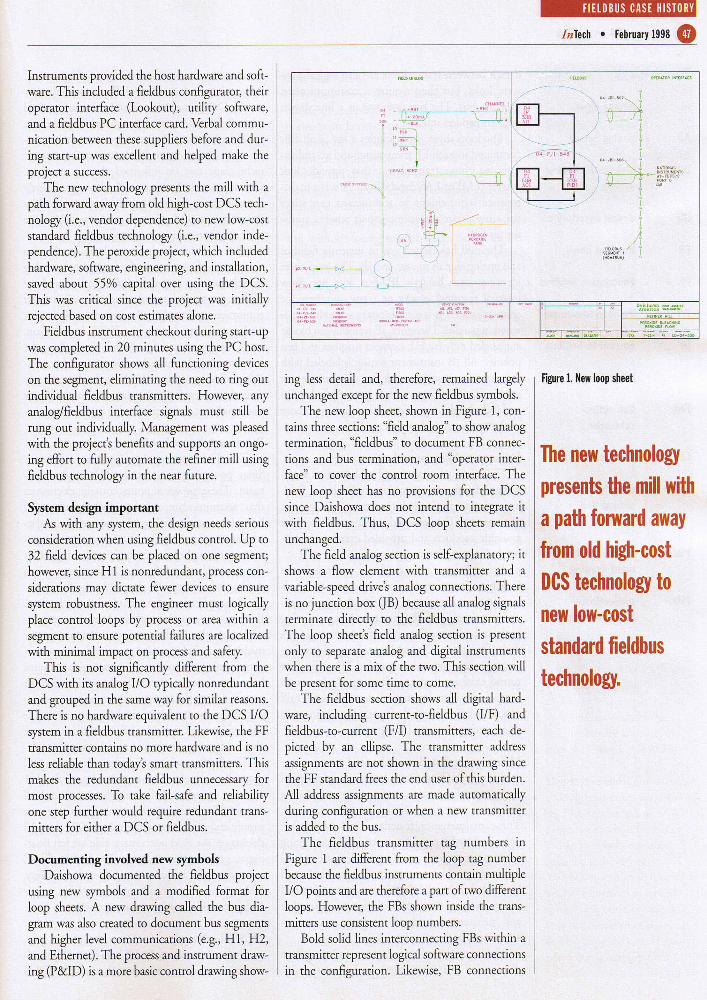
The new loop sheet, shown in Figure I, con-tains three sections: "field analog" to show analogtermination, 'fieldbus" to document FB connec-tions and bus termination, and "operator inter-face" to cover the control room interface. Thenew loop sheet has no provisions for the DCSsince Daishowa does not intend to integrate itwith fieldbus. Thus, DCS loop sheets remainunchanged.
The field analog section is self-explanatory; itshows a flow element with transmitter and avariable-speed drive's analog connections. Thereis no junction box OB) because all analog signalsterminate directly to the fieldbus transmitters.The loop sheet's field analog section is presentonly to separate analog and digital instrumentswhen there is a mix of the two. This section willbe present for some time to come.
The fieldbus section shows all digital hard-ware, including current-to-fieldbus (I/F) andfieldbus-ro-current (FII) transmitters, each de-picted by an ellipse. The transmitter addressassignments are not shown in the drawing sincethe FF standard frees the end user of this burden.All address assignments are made automaticallyduring configuration or when a new transmitteris added to the bus.
The fieldbus transmitter tag numbers inFigure I are different from the loop tag numberbecause the fieldbus instruments contain multipleI/O points and are therefore a part of two differentloops. However, the FBs shown inside the trans-mitters use consistent loop numbers.
Bold solid lines interconnecting FBs within atransmitter represent logical software connectionsin the configuration. Likewise, FB connections
DaishQW3. -.-....:wsArTH',u::ft""'_
JlUINt:I!WlI.l
Figure 1. New loop sheet
The new technologypresents the mill witha path forward awayfrom old high-costDeS technology tonew low-coststandard fieldbustechnology.

FIELDBUS CASE HISTORY
CD February 1998 • InTech
Terminology
AI analog input
AO analog output
DCS distributed controlsystem
DD device description
FB function block
FF Foundation field bus
F/I fieldbus-to-current
IIF current-to-fieldbus
JB junction box
LAS link activescheduler
LM link master
MAP manufacturingautomationprotocol
P&ID process and instru-ment drawing
PID proportional-integral-derivative
drawn berween transmitters are also logical soft-ware links, but they require a communicationover the bus. The bus is shown as a line drawnwith embedded squares.
The loop sheet also includes a list of all FBscontained in each FF transmitter and an indica-tion for those transmitters that provide linkmaster (LM) or LAS capabilities. This is a main-tenance requirement so technicians can selectthe appropriate replacement part when a trans-mitter fails.
The mill has elected not to intermix fieldbusand analog signals in anyone ]B. The loop sheetidentifies each fieldbus ]B, but does not showinternal terminal blocks or screw numbers forconnections. This is not necessarysince the bus iswired in parallel.Therefore,]B termination blocksare labeled only by HI segment number and buspolarity. All ]B instrument wiring is labeled withthe segment number and the transmitter tagname. The home-run wiring is similarly labeledand includes the segment number and a referenceto the upstream or downstream ]B.
Desktop training providedDaishowa purchased and evaluared all hard-
ware and software starter kits available for field-bus prior to final vendor selection and projectengineering. This ensured selection of the bestavailable products and provided excellent hands-on desktop engineering training.
In addition, one engineer attended theFieldbus Foundation's introductory and ad-vanced training classes. National Instrumentsalso provided in-mill custom training coveringbasic and advanced concepts for both engineersand technicians. One additional day of trainingfor engineers covered embedded FB coding forround card applications. Start-up week was anexceptional learning experience for both milland supplier personnel. Operator training wasdone during start-up by the mill.
Maintenance functions enhancedSome HART applications have implemented
automatic diagnostics and service schedulingbased on rwo-way digital communications.These maintenance functions will be furtherenhanced by FF providing interoperabiliry alongwith event-driven reporting and status of allinformation. Universal maintenance tools willbe needed to handle this open system, with endusers selecting the best tools for configurationand maintenance without investing in a propri-etary software/hardware package.
Fieldbus technology supports online failurediagnostics and preventive or predictive main-
tenance (e.g., continuous valve diagnostics).Although some of this capability is available nowon the DCS for a price, it will become standardwith fieldbus at little or no additional cost.Fieldbus failures will alarm operations with spe-cific detailed information so that instrumenttechnicians can be informed during a call-in.Online troubleshooting will also significantlyincrease the number of control loops serviced bythe technician. Most maintenance will be donewith simple transmitter replacement.
The technician's duties and skills will alsochange as industry moves from electronic analogtroubleshooting to purely digital. A bus analyzerto view protocol data units and other digital testequipment will replace the voltmeter and mostanalog tools used with the DCS. In addition,some maintenance documents, including theinstrument index and data sheets, will be avail-able online to update the host database at anytime. It is software of this diversity that will givethe supplier a competitive edge in the future.
Power supplies redundantThe Daishowa application uses redundant
Smar power supplies for the HI fieldbus seg-ment. These power supplies contain electronicsthat accommodate simple parallel wiring andbumpless transfer (fail-over).They are also isolat-ed and contain short-circuit and overcurrent pro-tection through power supply switching. Thiseliminates the need for fuse replacement whenthe bus is inadvertently shorted in the field.
The application also includes battery backup.Both power supplies and the batteries are con-nected to the fieldbus using a Releom powermultiplexer. Releom also provided the power-conditioning electronics to maintain constantbus impedance as field devices are added orremoved from the segment. Bus termination con-nections at both ends of the home run and spurconnections for individual field instruments arealso made using products from this supplier.
The fieldbus wiring includes a dedicated DCgrounding system. The negative leg of the HIsegment (power supplies and batteries) and allbus shields are tied to this ground at the powersupply end of the home run using a 00 cable. Allshields on the field instrument side are left float-ing to prevent ground loops. The building's ACgrounding grid is tied to the DC rods for safety.This arrangement significantly simplifies powerand grounding checkout during start-up.
DCS role changesOnly a fraction of the FF benefits will be real-
ized by the end user who elects to go with a DCS
FIELD BUS CASE HISTORY
InTech • February 1998 CDfor the fieldbus host. Since the host device is onlypartially covered in the final FF specification, it isnot subject to the same inreroperabiliry and con-formance testing as the field device and, there-fore, is not necessarily programmed using stan-dard FBs. Moreover, the host can include soft-ware for advanced control, process area and pro-duction coordination, FF segment (network)integration, control configuration, and operatorinterface. Placing any of these functions in theDCS for planrwide operation can lock the enduser into one supplier's host.
The alternative is to locate the advanced con-trol, process coordination, and segment integra-tion (HlIH2) into a field device that has passedthe rigorous FF testing and to locate the config-urator and operator interface software in a Pc.An industrially hardened field device with apowerful processor and a large nonvolatilememory capable of meeting these advanceddemands is well within reach with today's avail-able technology. Excellent PC-based fieldbusconfigurators and operator interface softwareare available now.
Integrating fieldbus with the DCS createsadditional problems as the end user must dealwith a hybrid of two entirely different systems.The FF specification contains specific detailedrequirements for user layer operations that aretotally different from any existing DCS. Itincludes specifics for FB initialization, operatingmodes, and configuration parameters. The speci-fication also defines data quality status and howit propagates through the FB configuration.Alarming and alarm priorities are also an integralpart of the FF specification. To integrate all ofthese differences into one system creates signifi-cant and unnecessary confusion and complexityfor the end user.
Daishowas plan for transition to fieldbustechnology uses a PC and software capable ofinterfacing to both fieldbus and the mill's DCS.The user interface for both systems can simulta-neously exist on one Pc, keeping the two sys-tems' operation totally independent. Daishowawill engineer new unit operations and someretrofit projects using fieldbus where appropri-ate. Existing DCS applications will be cur overto fieldbus in a future planned transition onlywhen there is justification to do so (e.g., DCSobsolescence or quality, productivity, and costincentives). Consequently, for an interim periodoperations, engineering, and maintenance mustbe trained for both FF and the DCS, bur not fora complex hybrid of the two. This keeps alloptions open for future growth and expansionin the mill.
Past and futureIt took more than a decade to develop and
release an acceptable FF specification. Now, near-ly two years hence, there is still very little to showin terms of available instrumentation and newindustrial applications. The same politics thatheld up the specification also held up its imple-mentation. Vendors delayed progress and strug-gled to determine how fieldbus could be imple-mented without obsoleting their existing systemsand without losing market share. Some recalledcapital investments made and lost in preparationfor manufacturing automation protocol (MAP)technology that never caught on in the processindustries several years back. Fortunately, most ofthese delays and politics have past and things arelooking up for the end user as many major man-ufacturers will finally release fieldbus productssometime this year.
New interoperable instrument technologymeans major change for the instrument suppli-ers. Hardware becomes a commodity. The unsat-isfied customer can simply remove an unaccept-able product from one supplier and replace itwith another more capable of meeting the needs(with little or no change to the control configu-ration). The process industries will finally achievevendor independence with more control overquality, productivity, and manufacturing costs byselecting the best available instruments and con-trols for the application.
Full utilization of fieldbus potential will taketime to exploit as it is limited only by the devel-oper's imagination. Supplier margins will shrinkas wide-open competition to exploit FF's newcapability heats up in an auempt to gain andmaintain market share. There are new kids on theblock and more will come with exceptional field-bus configuration, diagnostic, application, andmaintenance software and hardware tools.Powerful, industrially hardened fieldbus controlprocessors with large memories, silicon disks, andstandard software capable of both regulatory andadvanced controls will become available for fieldinstallation. Proprietary closed systems will bereplaced with standard open systems. Marketingand R&D strategies will change forever. The suc-cessful supplier will provide excellent customerservice, support, and software with full FF func-tionality to improve all aspects of plant operationand maintenance.
A long time in coming, Foundation fieldbushas arrived and is here to stay. It has a compre-hensive user layer with capabilities that areunprecedented in the process industries. It willrevolutionize process control, and the winner inall this is clearly the end user. IT
For further reading
Springer, R., et al. "RefinerPeroxide Bleaching at DaishowaPort Angeles," 1997 TAPPIPulping Conference, p. 463-469.
Behind the byline
Jason M. Mangano is a processand control engineer forDaishowa America Co. Lrd. inPort Angeles, Wash. He has aB.S. in chemical engineeringfrom me University ofIdaho.
Dan P.Dumdie is process andcontrol engineering supervisor atme Port Angeles mill ofDaishowa America. He has aB.S. in chemical engineeringfrom me University ofWashington and more than 20years of experience in processcontrol. His career objectiveshave placed special emphasis onmaking advanced control theorypractical and easily applied.