four-flow path high-efficiency nox and pm exhaust …€¦ · x and pm exhaust emission control...
TRANSCRIPT

2003-01-2305
Four-Flow Path High-Efficiency NOx and PM Exhaust Emission Control System for Heavy-Duty On-Highway Diesel Engines
Charles Schenk, Christopher Laroo, and Brian Olson U.S. EPA – Office of Transportation and Air Quality
Lee Fisher Analytical Engineering, Inc.
Copyright © 2003 Society of Automotive Engineers, Inc.
ABSTRACT
A 5.9 liter medium-heavy-duty diesel engine, meeting the emissions performance of a MY 2000 US heavy-duty on-highway engine, was tested with and without a diesel exhaust emission control system consisting of catalyzed diesel particulate filters and NOx adsorber catalysts arranged in a four-flow path configuration. This four-flow path system represents a significant reduction in catalyst volume when compared to previous systems tested by EPA. The goal of this project was to achieve high NOx reduction over the Heavy-Duty Diesel Engine Federal Test Procedure (HDDE-FTP) and Supplemental Emission Test (SET), consistent with the 2007 U.S. heavy-duty engine emissions standards, using this reduced volume system. Supply of hydrocarbon reductant for NOx adsorber regeneration was accomplished via a secondary exhaust fuel injection system. Alternating the restriction of the exhaust flow between the four-flow paths allowed reductant injection and adsorber regeneration to occur under very low space velocity conditions. Initial system tests showed impressive reductions of regulated pollutants. Emissions of NOx were reduced by 78% over the HDDE-FTP and 89% over the SET; and particulate matter (PM) emissions were reduced by 86% over the HDDE-FTP and SET. System improvements were identified during this testing which should allow the system to meet the 2007 emission targets. These improvements will be validated in future testing.
INTRODUCTION
The U.S. Environmental Protection Agency (U.S. EPA) has promulgated heavy-duty on-highway diesel engine emission standards of 0.2 g/hp-hr NOx, 0.01 g/hp-hr PM, and 0.14 g/hp-hr NMHC over the HDDE-FTP and the SET starting in 2007.1 These new standards will require highly efficient catalysts and other exhaust emission controls that can provide an order of magnitude reduction in diesel emissions beyond the 2004
emissions standards. This paper covers the fifth phase of the continuing program under way at the U.S. EPA – National Vehicle and Fuel Emissions Laboratory (U.S. EPA-NVFEL) to evaluate advanced exhaust emission control systems for heavy-duty on-highway diesel engines. The results of the first four testing phases have been previously reported.2-5 The results of phases 1 and 2 have shown that NOx adsorbers can achieve NOx reduction efficiencies greater than ninety percent after a modest accumulation of hours.2,3
A large amount of research has been performed and is still ongoing with respect to catalyst development; including the effects of thermal aging and poisoning due to sulfur exposure.4,6-21 Little or no work has been published addressing system integration and packaging, particularly with respect to system size and catalyst volume, in on-road heavy-duty diesel applications.2,3,22-26
Previous work by Schenk et. al. has shown that greater than 90% reductions in NOx and PM could be met using 72 liters of catalyst volume (37 L CDPF, 28 L NOx adsorber, and 7 L Diesel Oxidation Catalyst [DOC]) in a dual-flow path configuration.2,3 The primary focus of this paper will be to demonstrate an emission control system capable of providing large reductions in NOx and PM emissions over a broad range of engine operating conditions, while significantly reducing the catalyst volume and overall system cost when compared to previous systems. Our efforts are currently focused on the evaluation of a system that integrates catalyzed diesel particulate filters (CDPFs) for PM control with multiple-path NOx adsorbers for NOx control. All testing was performed using a newly developed four-flow path exhaust emission control system. Additional phases of this project not covered in this particular paper will be published in subsequent papers. Future related work is expected to include:
1. Further investigation of issues related to the thermal durability of NOx adsorber catalysts;

Figure 1. Schematic representation of the layout and function of the four-flow path exhaust emission control system (not to scale).
2. An extended catalyst durability test using the four-flow path exhaust emission control system;
3. Further investigation into the optimization of desulfation parameters;
4. System integration of the four-flow path exhaust emission control system onto a class 7 Freightliner demonstration truck.
TEST PROCEDURES
ENGINE DESCRIPTION
The engine used for testing the four-flow path exhaust emission control system was a 5.9-liter displacement Cummins ISB. The engine was identical to the engine used in phases 1 and 4 of this program and has been previously described.2,5 The major engine specifications are summarized in Table 1.
EXHAUST SYSTEM DESCRIPTION
NOx adsorber catalyst systems for lean gasoline and diesel applications have been previously described in detail.27-30 The regeneration/NOx reduction control strategies used in this application are similar to the ones previously used and have been described as parts of phases one, two, and four of this work.2,3,5
Figure 1 is a functional schematic of the four-flow path exhaust emission control system tested with the Cummins ISB engine. The configuration of this system was chosen to minimize system size and cost with respect to hardware.
The emission control system was fabricated from 316 stainless steel. A four-flow path configuration was chosen to minimize backpressure while still allowing NOx adsorber regeneration and desulfation to occur under low exhaust space velocities. The system was sized to approach the footprint of a typical medium-heavy-duty muffler. A size comparison can be seen in Figure 2. While the emission control system is approximately 30% longer than the muffler in its current state, opportunities for further reduction of the system size still exist.
In addition to a reduction in overall system size a significant reduction in catalyst volume was also achieved. Total catalyst volume for the system was reduced from 72 L in the two-flow path system to 33 L in the four-flow path system. While total NOx adsorber volume was reduced, total adsorbing volume remained nearly the same (14 L adsorbing volume for two-flow path system vs. 12 L adsorbing volume for four-flow path
Table 1. Summary of major engine specifications.2,4 Engine: 2000 Cummins ISB
Engine Configuration: 6-cylinder, turbocharged-aftercooled, DI diesel with 4-valves/cylinder
Rated Power: 194 kW (260 bhp) @ 2500 rpm Peak Torque: 895 N-m (660 ft-lb) @ 1600 rpm Fuel System: Bosch VP44 (Electronic Rotary) Bore X Stroke: 102 mm X 120 mm Engine Management: Stock Cylinder Displacement: 5.88 L Compression Ratio: 16.3:1

Figure 2. Size comparison of four-flow path system with a typical medium-heavy-duty diesel muffler.31
Figure 3. Schematic of four-flow path valve system.31
system). Each flow path contained one CDPF followed by two NOx adsorber substrates. The four flow paths rejoined at the collector, which houses the DOC. A summary of the major specifications of the CDPFs and NOx adsorbers used in this system can be found in Table 2. A prototype catalyzed Corning DuraTrap EC diesel particulate filter was used for PM reduction. This diesel particulate filter is similar in PM reduction performance to a Corning DuraTrap CO (EX-80), but is designed for lower soot-loaded pressure drop for both catalyzed and uncatalyzed diesel particulate filters.
The NOx adsorbers were chosen based on their performance over our thermal aging tests.5 These adsorbers were known to have good aging characteristics and reasonable high temperature performance. This combined with their desulfurization performance made them the choice for this testing. The adsorbers were relatively unaged during this testing and had about 33 hours at various speed and loads.
Exhaust path flow control was accomplished through the use of a four-flow path valve system. Figure 3 shows a schematic of the valve. The valve design incorporates the use of two Bimba Three-Position Rotary Actuators (Model #CPT-822), which act as pneumatic actuators to
control exhaust flow to each flow path. The valve positions were monitored using four Bimba Current Sinking (NPV) Hall Effect Switches (Model #HSK-04). The sensors were attached to the pneumatic actuators using Bimba Band Mounts (Model #D-35875-6).31 The space envelope required for this valve, as designed for a medium-duty diesel truck platform, is about 2.5 L. The valve is constructed such that any one or two flow paths can be closed to restrict exhaust flow during regeneration (though normally only one is closed at a time), or all of the flow paths can be opened to normal exhaust flow if desired. Valve response time is approximately 0.5 seconds, and a control algorithm insures that only one flow path at a time is closed during NOx adsorber regeneration.
Reductant injection was performed using a low cost, low-pressure fuel injector. This fuel injector was designed to deliver a fine atomization of fuel at injection pressures below 50 psi. A low-pressure fuel injection system was desired so that fuel can be supplied to the injectors from the engine lift pump circuit on most current diesel engine configurations. Low cost is achieved by the simple construction of the
Table 2. Summary of the major specifications of the exhaust emission control system components.
Device Monolith Type Cell
Density (cpsi)
Wall Thickness
(mil)
Diameter (inches)
Length (inches)
PGM Pt/Pd/Rh
PGM Loading
(g/ft3)
Base Metal Type**
Monolith Volume
(L)
Total Volume
(L)
CDPF Corning DuraTrap EC 200 12 5.66 6 1/0/0 50 n/a 2.47 9.88
NOx Adsorber
Corning Celcor 400 4 5.66 10 Trimetal* ∼100 Ba, K 4.12 16.48
DOC Corning Celcor 400 4 9.5 6 1/0/0 10 n/a 6.97 6.97
*Supplier did not provide the PGM ratio for combined 4” and 6” two substrate NOx adsorber assembly (totaling 10” in length per flow path). ** Supplier did not provide base metal loading information for the NOx adsorbers tested.

Figure 4. Injector cap and body (actual size).31
Figure 5. Valve assembly with reductant injectors as installed in NVFEL Heavy-Duty Engine Site 1.
injector, which comprises only two components, an injector cap and body, both machined from stainless steel (Figure 4).31 An ASCO two-way solenoid (Model #8225B008V) is used to control fuel flow to the injector. The solenoid is mounted with the injector in each individual flow path downstream of the valve (Figure 5). The valve body, reductant injectors, collector, and valve/injector drivers were fabricated, under contract, by Analytical Engineering Incorporated. Preliminary testing of the four-flow path emission control system produced higher than expected exhaust lambda (λ) values in the regenerating flow paths during NOx adsorber regeneration. The quantity of reductant injected during these events was more than sufficient for adsorber regeneration, yet measured exhaust lambda values remained greater than 1. This can be seen in the
“without cones” curves for flow paths 1, 2, and 3 in Figure 6. It is the authors’ belief that the lambda sensor’s proximity to the collector inlet (2.5 inches upstream) led to the elevated and inconsistent exhaust lambda values. This was due to a combination of flow stratification in the regenerating flow path and wrap around of lean exhaust from the three full flow paths into the rich regenerating flow path. This would dilute the rich pulse at the sensor, biasing the exhaust lambda
Figure 6. Lambda and reductant injection values with and without the use of the 18-inch long extension during NOx adsorber regeneration (each exhaust lambda trace was time aligned with the start of reductant injection.
Reductant Injector
Pneumatic Actuator

Figure 7. Emission control system as tested in Heavy-Duty Engine Site 1 with 18-inch extenders located between adsorber outlet and collector inlet.
measurement lean. This exhaust lambda measurement discrepancy was corrected through the addition of 18-inch long extensions added to all four-flow paths between the outlet of the rear NOx adsorber and collector inlet. This extension consisted of an inlet cone transitioning from a 5.9 inch id to a 2.5 inch id over 6 inches of length at 60°, followed by a 2.5 inch id X 6 inch long tube, followed by an outlet cone identical to the inlet cone, but in reverse. The ZrO2 NOx/O2 sensor was positioned in the center of the tube located between the two cones, positioning the sensor 16.5 inches from the collector inlet. This essentially eliminated the effects of backflow and stratification, allowing proper exhaust lambda measurement during NOx adsorber regeneration. Figure 7 shows the emission control system as tested at NVFEL Heavy-Duty Engine Site 1 with the addition of the 18-inch extenders. Future systems will integrate the small diameter tube into a more compact package than the current prototype. Figure 6 shows the regeneration exhaust lambda values for flow paths 0, 1, 2, and 3 after installation of the sensors in the extensions. It can be noted from the figure that the indicated exhaust lambda values became much more consistent flow path to flow path and significantly less fuel was required to achieve the indicated λ < 1. The figure also shows very clearly that flow path 1 has a different valve leakage rate when compared to the other 3 flow paths. The low leakage was indicated by the long duration that the flow path held λ < 1 during regeneration and that flow path required approximately half of the fuel for adsorber regeneration when compared to the other three flow paths. This was a desirable feature, and efforts will be made to obtain similar regeneration flow rates on the other three flow paths for future testing. TEST FUEL
The fuel used in this work was Phillips Chemical Company Lot 1HPULD01. This fuel was similar to the fuel specified by the U.S. Department of Energy’s (U.S. DOE) Diesel Emission Control – Sulfur Effects (DECSE) program to have similar properties to today’s on-highway diesel fuel with the exception of zero sulfur content.20,21
The fuel properties are shown in Table 3. A very low sulfur fuel was chosen to minimize the impact of sulfur poisoning on NOx adsorber performance. Fuel sulfur content was measured using x-ray fluorescence spectroscopy (XRF), which had a 0.7-ppm limit of detection (LOD) for sulfur. XRF indicated a fuel sulfur concentration that was below the LOD for the instrument.
TEST CYCLES
The engine was tested over two different dynamometer test cycles:
1. The Supplemental Emission Test weighted steady-state modes1
2. The hot-start Heavy-Duty Diesel Engine Federal Test Procedure transient cycle1
The SET is essentially the same as the European Steady-State Cycle, except that the test cell conditions and emissions measurement procedures follow those specified in 40 CFR § 86 Subpart N.1 The SET was run as a sequence of steady state modes, from the coldest to the hottest in order to minimize stabilization time and to allow individual PM measurements to be taken at each mode.
LABORATORY
The engine and exhaust emission control system was tested at Heavy-Duty Engine Site 1 at the U.S. EPA – NVFEL facility in Ann Arbor, MI. The test site is equipped with a 600 hp DC dynamometer and a Horiba full-flow CVS and particulate measurement system.
Table 3. Summary of diesel fuel properties.
Test Method Results Net Heat of Combustion, ASTM D3338-92 (MJ/kg) 43.06
Density @ 15.5°C (g/cm3) 0.8348 Cetane Number 44.8 Cetane Index 50.6 Olefins, FIA D1319-93 (% Vol.) 3.2 Aromatics, D1319-93 (% Vol.) 24.5 Sulfur, ASTM D2622 (ppm mass) < 0.7 Carbon, ASTM D3343-95 (% mass) 0.8659 Distillation Properties, ASTM D86
IBP (°C): 181 10 % (°C): 205 50 % (°C): 259 90 % (°C): 318
End Point (°C): 351 Residue Diesel (mL): 0
Recovery: 100%
Extender
Flow

Table 4. Exhaust fuel-reductant injection schedule over the SET.
SET Mode
Regeneration Period (s)
Injection Duration (s)
Injection Rate
(g/min) 1 -- -- -- 2 30 3.8 85 3 45 3.5 85 4 40 4.5 85 5 38 3.8 85 6 40 4.5 85 7 60 2.1 85 8 23 3.8 85 9 60 2.4 85 10 20 3.8 85 11 30 2.8 85 12 37 4.5 85 13 40 3.8 85
Dilute gaseous regulated emissions were measured using a Horiba MEXA 7200D analyzer bench as per 40 CFR § 86 Subpart N.1 Some of the recent changes to the Subpart N procedures for measurement of NOx and PM emissions from post-2007 heavy-duty on-highway diesel engines were also implemented during this testing.1 This included the use of new high-efficiency PM filter sample media and filter sample holders as specified for low-concentration PM measurement. A bag system was also used to provide a redundant measurement of dilute NOx emissions in addition to the more usual continuous dilute NOx measurement.1 PM measurements for SET testing did not follow the single test filter procedure outlined in 40 CFR § 86.1360-2007. Individual sample filters were used for each mode and the modal weighting factors were applied to PM emission rate and power.
NOX ADSORBER REGENERATION STRATEGY
Steady State Testing
Testing at SET steady-state speed-load conditions was conducted using a semi-automatic controller implemented in LabView. The general strategy was to inject sufficient fuel during regeneration to achieve exhaust conditions fuel-rich of stoichiometric (0.85 < λ < 1). The fuel quantity injected was calculated based on engine speed, engine load, and catalyst outlet temperature. The regeneration frequency was set to fixed intervals to achieve the desired tradeoff between NOx performance and fuel consumption.
Transient Testing
The transient HDDE-FTP results presented were for hot-start transient cycles only. The exhaust emission control system was not optimized for cold start performance and would not provide a meaningful assessment of cold-start performance at this time. Catalyst preconditioning, particularly with respect to catalyst temperature, was found to be very critical. In order to best simulate the standard “cold-soak-hot” procedure, the catalyst system was soaked for 20 minutes between each cycle (i.e. hot HDDE-FTP-soak-HDDE-FTP).
Regeneration control for the hot-start HDDE-FTP transient testing was accomplished using an automatic regeneration controller. Instead of the fixed regeneration frequency used in the steady state modes, the regenerations were controlled automatically. Regenerations were triggered by NOx slip measured downstream of the catalyst system. The NOx slip targets were calculated from engine speed and load. Once regeneration was initiated, the end of the regeneration cycle was determined by a λ > 1 or time. As the exhaust lambda value in the regenerating flow path rose back above λ = 1 or a maximum regeneration time was exceeded, the regenerating flow path was opened to full flow again (all flow paths open) until NOx slip triggered regeneration of the next flow path.
RESULTS
STEADY-STATE SET RESULTS
The regeneration calibrations for each of the SET modes are shown in Table 4. Modal and composite SET NOx, hydrocarbon, and PM emission results are presented in Tables 5 and 6. The weighted composite SET NOx emission of 0.36 g/hp-hr represented an 89% reduction from conditions without the NOx adsorber catalyst system. NOx reduction efficiency over the SET was comparable to the results of phases 1 and 2 of this test program which used the two-flow path emission control system.2,3 Since the adsorbers used in this testing were different formulations than those used in previous testing, the NOx reduction performance as a function of temperature (Figure 8) was also different. The high temperature performance of the new formulation was not quite as good as the older formulation as evidenced by high temperature modes 8 and 10. The old formulation had NOx reductions of 91% and 95% respectively at these modes, compared to 85% and 75% with the new formulation. The tradeoff is that the new formulation has the ability to be desulfated at lower temperatures and has been shown to provide better aging performance.5
PM emission results of 0.009 g/hp-hr were demonstrated for the SET. This was a substantial reduction from the baseline emissions. Hydrocarbon emissions for the SET composite were 0.11 g/hp-hr, which was a reduction from the 0.17 g/hp-hr without the catalyst system. The fuel economy penalty for the SET due to reductant injection was 1.6%.
TRANSIENT HDDE-FTP RESULTS
Transient emissions results over the hot-start HDDE-FTP transient cycle are summarized in Table 7. Brake specific values are given for continuous measurements only. Details of the regeneration events and cumulative NOx and HC emissions over the hot-start HDDE-FTP are presented in Figures 9 – 12 (a and b). The combination

Table 5. Modal and composite SET NOx and HC emissions results for the Modified Cummins ISB engine. Cummins ISB (baseline) Cummins ISB w/post-combustion emission controls
SET Mode
SET Weighting
Speed (rpm)
Torque (lb-ft)
BSNOx (g/hp-hr)
BSHC (g/hp-hr)
Outlet T (°C)
BSNOx (g/hp-hr)
NOx (% Reduction)
BSHC (g/hp-hr)
Reductant FE Impact (%)*
1 15% Idle 0 0.00 0.00 144 0.16 100% 0.00 0.0% 2 8% 1616 649 3.48 0.10 475 0.29 92% 0.06 1.4% 3 10% 1943 331 3.06 0.22 355 0.08 97% 0.11 1.4% 4 10% 1942 495 2.98 0.13 419 0.14 95% 0.07 1.3% 5 5% 1615 335 3.50 0.26 368 0.13 96% 0.11 2.1% 6 5% 1616 500 3.45 0.15 426 0.11 97% 0.08 1.6% 7 5% 1614 169 5.25 0.53 251 0.72 86% 0.27 1.5% 8 9% 1942 635 3.16 0.09 496 0.47 85% 0.06 1.5% 9 10% 1941 167 4.46 0.57 291 0.60 87% 0.44 4.3%
10 8% 2271 594 3.24 0.08 509 0.80 75% 0.07 1.6% 11 5% 2269 153 3.81 0.71 282 0.67 82% 0.36 2.5% 12 5% 2270 453 3.21 0.11 406 0.19 94% 0.06 1.3% 13 5% 2269 303 3.17 0.19 343 0.19 94% 0.17 1.4% SET Weighted Composite Results: 3.33 0.17 0.36 89% 0.11 1.6%**
* Fuel economy impact of fuel-reductant addition for NOx adsorber regeneration. ** Increased exhaust restriction from the wall-flow and flow through monoliths results in a further FE impact of approximately 1-2% over the SET composite.
Table 6. Modal and composite SET PM emissions results for the Modified Cummins ISB engine.
SET Mode SET Weighting
Speed (rpm)
Torque (lb-ft)
BSPM (g/hp-hr) Without Post Combustion
Emission Controls
BSPM (g/hp-hr) With Post
Combustion Emission Controls
1 15% Idle 0 0.000 0 2 8% 1616 649 0.057 0.004 3 10% 1943 331 0.058 0.014 4 10% 1942 495 0.067 0.010 5 5% 1615 335 0.062 0.011 6 5% 1616 500 0.048 0.008 7 5% 1614 169 0.113 0.012 8 9% 1942 635 0.068 0.009 9 10% 1941 167 0.094 0.006 10 8% 2271 594 0.073 0.008 11 5% 2269 153 0.130 0.006 12 5% 2270 453 0.056 0.008 13 5% 2269 303 0.000 0.015
SET Weighted Composite Results: 0.065 0.009
of CDPFs, NOx adsorbers, and DOC reduced brake specific emissions of PM, and CO by 85% or greater and NOx by 78% when compared to the baseline condition (no post-combustion emission controls). However the HC emissions increased relative to the baseline. The fuel economy impact due to exhaust fuel injection for NOx adsorber regeneration was 3.4%.
It can be seen from Figures 9 – 12 that there is small but significant NOx slip occurring over the first 640 seconds of the cycle. During this part of the cycle adsorber temperatures fluctuated between 200°C and 250°C (Figure 13, temperature downstream of DOC with insulation). The NOx adsorber efficiency is relatively low in this temperature range (Figure 8), allowing the
observed slip. More than half the NOx slip occurred between 640 and 690 seconds (Figure 11). During this time the engine transitions from a very low average BMEP to a much higher BMEP. The engine exhaust has a much higher NOx mass rate at these high BMEPs, but the NOx adsorbers were still below their optimum operating temperature. The adsorbers didn’t reach their optimum temperature until about 750 seconds into the cycle. The majority of the cycle NOx slip occurred during this warm-up period when the catalyst temperatures were still below the optimum temperature and engine NOx output was high.
The low temperatures experienced during the transient cycle were due in part to the low mass and high surface
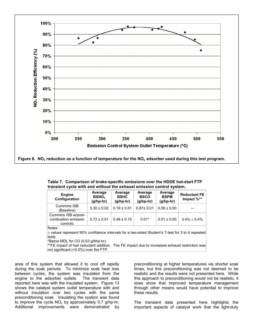
Table 7. Comparison of brake-specific emissions over the HDDE hot-start FTP transient cycle with and without the exhaust emission control system.
Engine Configuration
Average BSNOx
(g/hp-hr)
Average BSHC
(g/hp-hr)
Average BSCO
(g/hp-hr)
Average BSPM
(g/hp-hr) Reductant FE
Impact %**
Cummins ISB (Baseline) 3.30 ± 0.02 0.19 ± 0.01 0.87± 0.01 0.09 ± 0.00 --
Cummins ISB w/post-combustion emission
controls 0.73 ± 0.01 0.48 ± 0.15 0.01*
0.01 ± 0.00
3.4% ± 0.4%
Notes: ± values represent 95% confidence intervals for a two-sided Student’s T-test for 3 to 4 repeated tests. *Below MDL for CO (0.03 g/bhp-hr). **FE impact of fuel reductant addition. The FE impact due to increased exhaust restriction was not significant (<0.5%) over the FTP.
area of this system that allowed it to cool off rapidly during the soak periods. To minimize soak heat loss between cycles, the system was insulated from the engine to the adsorber outlets. The transient data reported here was with the insulated system. Figure 13 shows the catalyst system outlet temperature with and without insulation over two cycles with the same preconditioning soak. Insulating the system was found to improve the cycle NOx by approximately 0.7 g/hp-hr. Additional improvements were demonstrated by
preconditioning at higher temperatures via shorter soak times, but this preconditioning was not deemed to be realistic and the results were not presented here. While this approach to preconditioning would not be realistic, it does show that improved temperature management through other means would have potential to improve these results.
The transient data presented here highlights the important aspects of catalyst work that the light-duty
Figure 8. NOx reduction as a function of temperature for the NOx adsorber used during this test program.

(a)
(b)
Figure 9. Cumulative emissions results (a) for engine operation of the first 300 seconds (New York Nonfreeway) of the HDDE Hot-Start FTP Transient Cycle (b).

(a)
(b)
Figure 10. Cumulative emissions results (a) for engine operation over the second 300-second period (Los Angeles Nonfreeway) of the HDDE Hot-Start FTP Transient Cycle (b).

(a)
(b)
Figure 11. Cumulative emissions results (a) for engine operation over the third 300-second period (Los Angeles Freeway) of the HDDE Hot-Start FTP Transient Cycle (b).

(a)
(b)
Figure 12. Cumulative emissions results (a) for engine operation over the fourth 300-second period (repeat of New York Nonfreeway) of the HDDE Hot-Start FTP Transient Cycle (b).

sector has known for years: Thermal management and engine/catalyst integration are the keys to success. Though insulating the system improved system performance, it was clear that other measures would be required. Close mounting the catalyst system would help system warm-up, but the engine out temperature for our test engine does not exceed 300°C until nearly 600 seconds into the HDDE FTP. Therefore, the improvement due to location alone is not likely to be significant. Reducing the thermal mass of the catalyst system would also help, but with engine out temperatures hovering below 250°C over the first half of the cycle, the catalysts will still not be in their optimum operating temperature window.
Increasing exhaust temperatures through engine management could significantly improve the results shown here. Toyota has published a number of papers detailing their efforts to integrate the diesel catalysts and engine systems for passenger car applications.23-26 One of the key aspects of their integration is controlling the catalyst temperature. EGR, post injection, exhaust injection, and other strategies are used to keep the adsorber at its optimum NOx reduction temperature. These strategies are also used to periodically regenerate the PM trap.
Hydrocarbon emissions were also higher than desired due to slip during NOx regenerations (Table 7). This HC
slip was caused by a combination of factors that still need to be optimized in our system. The primary factor is, again, the low catalyst temperature and the resulting low oxidation efficiency. Second, the four-flow path system’s regeneration exhaust mass flow has not been optimized yet. The leakage past the exhaust valve was higher than necessary when it was closed, increasing both the fuel consumption due to reductant injection and the HC slip, as well as effecting NOx control. This hardware issue can be resolved by improving the valve seal. Third, the automatic controller had a ‘choke’-like function that increased regeneration fueling when the catalyst temperature was cold. This ‘choke’ function was overcompensating for the cold catalyst temperatures, particularly at high engine loads (note the HC increase at the 650 second mark in Figure 11). This and other refinements to the controller will contribute to much lower HC emissions. Finally, the DOC function could be improved, both by increased oxidation activity and perhaps improved collector mixing. The DOC used for this testing had modest PGM loading and commensurate performance. Higher loadings would improve oxidation performance. The collector’s ability to mix exhaust has also not yet been well determined. The DOC works best in a net lean environment, but as currently configured, the flow through the DOC may be stratified such that the three lean flow paths do not significantly mix with the rich flow from the regenerating
Figure 13. Exhaust temperature profile of engine out exhaust, emission control system outlet with insulation, and emission control system outlet without insulation over HDDE-FTP (each test preceded by a 20-minute soak). Temperature measurement location is denoted in parenthesis in the legend.

flow path. The high HC emissions also, to some extent, contributed to the measured PM level.
CONCLUSION
The compact four-flow path system achieved approximately 90% NOx reduction over the SET composite test and approximately 80% NOx reduction over the HDDE-FTP. PM emissions were also reduced by 86% over both tests to a level compliant with the 2007 U.S. heavy-duty engine emission standard. These reductions were accomplished with less than half the catalyst volume of the previous system. The system hardware is still very early in its development. This is most evident in the high HDDE-FTP HC and NOx emissions. The target for this program is ultimately to achieve greater than 90% NOx reductions over both cycles (with > 2.5 g/hp-hr engine out) and to meet the 2007 NOx, PM and HC standards with a minimal impact on fuel economy. Currently the PM targets have been achieved, but the NOx and HC emissions are greater than desired.
The primary path of improvement will be to integrate the engine with the catalyst system in order to raise the exhaust temperature at light loads, improving the systems ability to store and reduce NOx. So far the testing performed at our lab has treated the engine and catalyst systems as separate entities. Future testing will integrate the engine and catalyst controls to better tailor the engine exhaust to the needs of the catalysts.
In addition to the integration work, there are a number of improvements that can be made to the current four-flow path system hardware and control algorithm. Regeneration exhaust flow can be lowered to reduce regeneration HC slip and overall fuel consumption. Improved mixing of the four flow paths upstream of the DOC may also reduce HC slip. Improvements are also needed in the method used by the control algorithm to determine the regeneration fuel calculation.
Further cooperative development of the NOx adsorber/CDPF approach to diesel exhaust emission control will continue at the U.S. EPA-NVFEL facility, and will be the topic of subsequent papers.
ACKNOWLEDGMENTS
The authors would like to thank Tim Davis, Manish Patel, Mike Murphy, and Dan Stokes for their contributions to this testing; including test cell operation/setup and modification/installation of the four-flow path exhaust emission control system used in this work. Also, we would like to thank MECA and its member companies for their assistance in obtaining the catalyzed devices crucial to this test program.
REFERENCES
1. Code of Federal Regulations; Title 40; Part 86; U.S. Environmental Protection Agency, U.S. Government Printing Office: Washington, DC, July 1, 2001.
2. Schenk C.; McDonald, J.; Olson, B. High-Efficiency NOx and PM Exhaust Emission Control for Heavy-Duty On-Highway Diesel Engines. Soc. Automot. Eng. Tech. Pap. Ser. 2001, No. 2001-01-1351.
3. Schenk, C.; McDonald, J.; Laroo, C. High-Efficiency NOx and PM Exhaust Emission Control for Heavy-Duty On-Highway Diesel Engines – Part Two. Soc. Automot. Eng. Tech. Pap. Ser. 2001, No. 2001-01-3619.
4. Laroo, C.; Schenk, C.; Olson, B.; Way, P.; McDonald, J. NOx Adsorber Desulfation Techniques for Heavy-Duty On-Highway Diesel Engines. Soc. Automot. Eng. Tech. Pap. Ser. 2002, No. 2002-01-2871.
5. Schenk, C.; Laroo, C. NOx Adsorber Aging on a Heavy-Duty On-Highway Diesel Engine – Part 1. Soc. Automot. Eng. Tech. Pap. Ser. 2003, No. 2003-01-0042.
6. Hachisuka, I., Hirata, H.; Ikeda, Y.; Matsumoto, S. Deactivation Mechanisms of NOx Storage-Reduction Catalysts and Improvements of Its Performance. Soc. Automot. Eng. Tech. Pap. Ser. 2000, No. 2000-01-1196.
7. Dou, D.; Balland, J. Impact of Alkali Metals on the Performance and Mechanical Properties of NOx Adsorber Catalysts. Soc. Automot. Eng. Tech. Pap. Ser. 2002, No. 2002-01-0734.
8. Dou, D.; Bailey, O. H. Investigation of NOx Adsorber Catalyst Deactivation. Soc. Automot. Eng. Tech. Pap. Ser. 1998, No. 982594.
9. Heck, R.; Farrauto, R. Catalytic Air Pollution Control Commercial Technology; John Wiley & Sons: New York, 1995; pp 63-67.
10. Dearth, M.; Hepburn, J. S.; Thanasiu, E.; McKenzie, J.; Horne, G. S. Sulfur Interaction with Lean NOx Traps: Laboratory and Engine Dynamometer Studies. Soc. Automot. Eng. Tech. Pap. Ser. 1998, No. 982595.
11. Erkfeldt, S.; Larsson, M.; Hedblom, H.; Skoglundh, M. Sulfur Poisoning and Regeneration of NOx Trap Catalyst for Direct Injected Gasoline Engines. Soc. Automot. Eng. Tech. Pap. Ser. 1999, No. 1999-01-3504.
12. Asanuma, T.; Takeshima, S.; Yamashita, T.; Tanaka, T.; Murai, T.; Iguchi, S. Influence of Sulfur Concentration in Gasoline on NOx Storage-Reduction Catalyst. Soc. Automot. Eng. Tech. Pap. Ser. 1999, No. 1999-01-3501.
13. Hodjati, S.; Semelle, F.; Moral, N.; Bert, C.; Rigaud, M. Impact of Sulfur on the NOx Trap Catalyst Activity-Poisoning and Regeneration Behavior. Soc. Automot. Eng. Tech. Pap. Ser. 2000, No. 2000-01-1874.
14. Li, J.; Theis, J. R.; Chun, W.; Goralski, C. T.; Kudla, R. J.; Watkins, W. L.; Hurley, R. H. Sulfur Poisoning and Desulfation of the Lean NOx Trap. Soc.

Automot. Eng. Tech. Pap. Ser. 2001, No. 2001-01-2503.
15. Parks, J.; Watson, A.; Campbell, G.; Epling, B. Durability of NOx Adsorbers: Effects of Repetitive Sulfur Loading and Desulfation. Soc. Automot. Eng. Tech. Pap. Ser. 2002, No. 2002-01-2880.
16. Amberntsson, A.; Skoglundh, M.; Jonsson, M.; Fridell, E. Investigations of Sulphur Deactivation of NOx Storage Catalysts: Influence of Sulphur Carrier and Exposure Conditions. Catal. Today 2002, 2665, uncorrected proof.
17. Cutler, W. A.; Day, J. P. Mechanical Durability of Cordierite-Based NOx Adsorber/Catalyst Systems for Lean Burn Gasoline Applications. Soc. Automot. Eng. Tech. Pap. Ser. 1999, No. 1999-01-3500.
18. Iwachido, K.; Tanada, H.; Wantanabe, T.; Yamada, N.; Nakayama, O.; Ando, H.; Hori, M.; Taniguchi, S.; Noda, N.; Abe, F. Development of the NOx Adsorber Catalyst for Use with High-Temperature Conditions. Soc. Automot. Eng. Tech. Pap. Ser. 2001, No. 2001-01-1298.
19. Ando, H. High-Temperature Lean NOx Catalyst and Catalyst Reaction Management. Auto Technology 2001, 70 (4).
20. Diesel Emission Control – Sulfur Effects (DECSE) Program: NOx Adsorber Catalysts; Phase II Summary Report; U.S. Department Of Energy, Office of Transportation Technologies, U.S. Government Printing Office: Washington, DC, October 2000.
21. Diesel Emission Control – Sulfur Effects (DECSE) Program: Diesel Oxidation Catalysts and Lean-NOx Catalysts; Final Report; U.S. Department Of Energy, Office of Transportation Technologies, U.S. Government Printing Office: Washington, DC, June 2001.
22. McDonald, J.; Bunker, B. Testing of the Toyota Avensis DPNR at U.S. EPA-NVFEL. Soc. Automot. Eng. Tech. Pap. Ser. 2002, No. 2002-01-2877.
23. Sasaki, S.; Ito, T.; Iguchi, S. Smoke-less Rich Combustion by Low Temperature Oxidation in Diesel Engines. Proceedings of the 9th Aachen Colloquium on Automobile and Engine Technology, Aachen, Germany, October 4-6, 2000.
24. Nakatani, K.; Hirota, S.; Takeshima, S.; Itoh, K.; Tanaka, T.; Dohmae, K. Simultaneous PM and NOx Reduction System for Diesel Engines Soc. Automot. Eng. Tech. Pap. Ser. 2002, No. 2002-01-0957.
25. Paquet, T.; Tahara, J.; Sugiyama, T.; Hirota, S.; Matsuoka, H.; Fujimura, T. First Test Results of a Field Trial with Diesel Passenger Cars, Equipped
with the DNPR Exhaust Aftertreatment System. Proceedings of the 11th Aachen Colloquium on Automobile and Engine Technology, Aachen, Germany, October 7-9, 2002; p 801.
26. Fujimura, T.; Matushita, S.; Tanaka, T.; Koichi, K. Development Towards Serial Production of a Diesel Passenger Car with Simultaneous Reduction System of NOx and PM for the European Market. Proceedings of the 23rd International Vienna Motor Symposium, Vienna, Austria, April 25-26, 2002; p 156.
27. Miyoshi, N.; Matsumoto, S.; Katoh K.; Tanaka, T.; Harada, J.; Takahashi, N; Yokota, K.; Sugiura, M.; Kasahara, K. Development of New Concept Three-Way Catalyst for Automotive Lean-Burn Engines. Soc. Automot. Eng. Tech. Pap. Ser. 1995, No. 950809.
28. Brogan, M. S.; Brisley, R. J.; Walker, A. P., Webster, D. E.; W. Boegner, N.P. Fekete, M. Kramer, B. Krutzsch, Voightlander, D. Evaluation of NOx Storage Catalysts as an Effective System for NOx Removal from the Exhaust Gas of Lean Burn Gasoline Engines. Soc. Automot. Eng. Tech. Pap. Ser. 1995, No. 95490.
29. Strehlau, W.; Leyrer, J.; Lox, E.S.; Kreuzer, T.; Hori, M.; Hoffman, M. New Developments in Lean NOx Catalysis for Gasoline Fueled Passenger Cars in Europe. Soc. Automot. Eng. Tech. Pap. Ser. 1996, No. 962047.
30. Krämer, M.; Abthoff, J.; Duvinage, F.; Ruzicka, N.; Krutzsch, B.; Liebscher, T. Possible Exhaust Gas Aftertreatment Concepts for Passenger Car Diesel Engines with Sulphur-free Fuel. Soc. Automot. Eng. Tech. Pap. Ser. 1999, No. 1999-01-1328.
31. May, D.; May, A.; Schenk C.; Fisher, L.; Krempel, L. Exhaust Aftertreatment System and Method for an Internal Combustion Engine. U.S. Pat. Appl. Filed, November 27, 2002.
CONTACT
Charles Schenk United States Environmental Protection Agency Office of Transportation and Air Quality Assessment and Standards Division 2000 Traverwood Dr. Ann Arbor, MI 48105 Phone: (734) 214-4700 E-mail: [email protected]