four-span ps concrete beam aashto type iii continuous ... · pdf filedetailed example...
TRANSCRIPT

Four-Span PS Concrete Beam AASHTO Type III Continuous Spans Input
As-Built Model Only
November, 2011
VDOT VERSION 6.2 1

DETAILED EXAMPLE
FOUR-SPAN PS CONCRETE BEAM AASHTO TYPE III CONTINUOUS SPANS INPUT
ONLY FOR AS-BUILT MODEL
Page No.
Cover Sheet 1 Table of Contents 2 Bridge Information 3-6 Material Properties Input 7-14 Beam Shape 15-16 Parapet 17 Impact and Factors 18-19 Superstructure Definition (using the Diaphragm Wizard) 20-35 G1 Input 36-59 Linking Girders 60-61 G2 Input (copying properties from G1 and modifying) 62-72 Bridge Alternative (using the Superstructure Wizard) 73-77 Rating Bridge and Review the Output (at both bridge and member level) 78-100 MathCAD calculations 101-103 Superstructure Bridge Plans (plan, elevation, beam and deck details, deck plan) 104-108
VDOT VERSION 6.2 2

FOUR-SPAN PS CONCRETE BEAM AASHTO TYPE III CONTINUOUS SPANS INPUT BRIDGE INFORMATION
VDOT VERSION 6.2 3

FOUR-SPAN PS CONCRETE BEAM AASHTO TYPE III CONTINUOUS SPANS INPUT BRIDGE INFORMATION
To create a new bridge right click on the folder where you want to save the bridge and choose New – New Bridge. New window will appear, fill the data as shown below. See bridge plans for bridge information.
Template: Template bridges serve as templates to help develop other bridges. Bridge Completely Defined: Check the box if the specified bridge is completely defined within the Virtis/Opis database. Do not check this box if some of the structures making up the bridge are not in the database. BridgeWare Association… button: Opens the BridgeWare Association window allowing you to specify this current bridge as a Virtis, Opis or Virtis/Opis bridge and also to link this current bridge to a bridge in the Pontis database if Pontis is installed.
Create new bridge
Input bridge type and plan number
Federal ID
VDOT VERSION 6.2 4
FOUR-SPAN PS CONCRETE BEAM AASHTO TYPE III CONTINUOUS SPANS INPUT BRIDGE INFORMATION
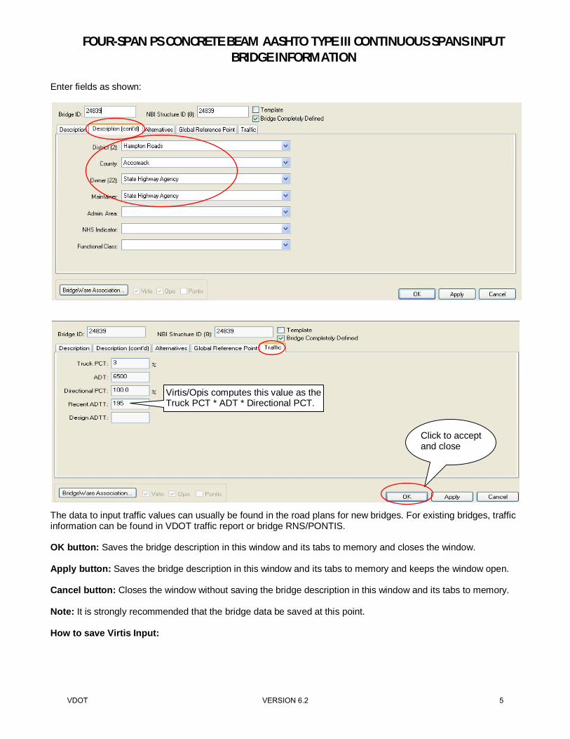
Enter fields as shown:
The data to input traffic values can usually be found in the road plans for new bridges. For existing bridges, traffic information can be found in VDOT traffic report or bridge RNS/PONTIS. OK button: Saves the bridge description in this window and its tabs to memory and closes the window. Apply button: Saves the bridge description in this window and its tabs to memory and keeps the window open. Cancel button: Closes the window without saving the bridge description in this window and its tabs to memory. Note: It is strongly recommended that the bridge data be saved at this point. How to save Virtis Input:
Virtis/Opis computes this value as the Truck PCT * ADT * Directional PCT.
Click to accept and close
VDOT VERSION 6.2 5

FOUR-SPAN PS CONCRETE BEAM AASHTO TYPE III CONTINUOUS SPANS INPUT BRIDGE INFORMATION
Click to save
Click to save
VDOT VERSION 6.2 6

FOUR-SPAN PS CONCRETE BEAM AASHTO TYPE III CONTINUOUS SPANS INPUT MATERIAL PROPERTIES INPUT
4 ksi concrete for deck:
Copy from Library button: Opens the Library - Materials - Concrete window, allowing you to copy a set of concrete material properties from the library to this window.
Double click to open
Click to use data from library
Click to accept
VDOT VERSION 6.2 7

FOUR-SPAN PS CONCRETE BEAM AASHTO TYPE III CONTINUOUS SPANS INPUT MATERIAL PROPERTIES INPUT
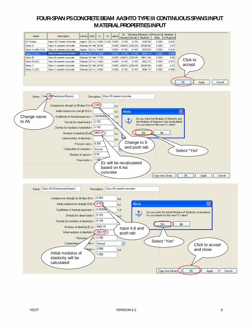
Based on bridge plans, 6 ksi concrete (Class A5) with initial 4.8 ksi for PS Concrete beams:
Click to accept and close
Double click to open
Click to use data from library
VDOT VERSION 6.2 8
FOUR-SPAN PS CONCRETE BEAM AASHTO TYPE III CONTINUOUS SPANS INPUT MATERIAL PROPERTIES INPUT
Click to accept
Change name to A5
Click to accept and close
Change to 6 and push tab
Select “Yes”
Ec will be recalculated based on 6 ksi concrete
Select “Yes”
Input 4.8 and push tab
Initial modulus of elasticity will be calculated
VDOT VERSION 6.2 9

FOUR-SPAN PS CONCRETE BEAM AASHTO TYPE III CONTINUOUS SPANS INPUT MATERIAL PROPERTIES INPUT
Based on bridge plans, reinforcing steel for deck is epoxy coated and for beams is galvanized. Grade 60 ksi epoxy coated reinforcing steel for deck:
Double click to open
Click to use data from library
Click to accept
VDOT VERSION 6.2 10

FOUR-SPAN PS CONCRETE BEAM AASHTO TYPE III CONTINUOUS SPANS INPUT MATERIAL PROPERTIES INPUT
Grade 60 ksi galvanized reinforcing steel for beams:
Click to accept and close
Click for Epoxy Coated
Double click to open
Click to use data from library
VDOT VERSION 6.2 11

FOUR-SPAN PS CONCRETE BEAM AASHTO TYPE III CONTINUOUS SPANS INPUT MATERIAL PROPERTIES INPUT
Prestress strand:
Double click to open
Click to accept
Click to accept and close
Click for Galvanized
VDOT VERSION 6.2 12

FOUR-SPAN PS CONCRETE BEAM AASHTO TYPE III CONTINUOUS SPANS INPUT MATERIAL PROPERTIES INPUT
Click to use data from library
Click to accept
VDOT VERSION 6.2 13

FOUR-SPAN PS CONCRETE BEAM AASHTO TYPE III CONTINUOUS SPANS INPUT MATERIAL PROPERTIES INPUT
Click to accept and close
VDOT VERSION 6.2 14
FOUR-SPAN PS CONCRETE BEAM AASHTO TYPE III CONTINUOUS SPANS INPUT BEAM SHAPE
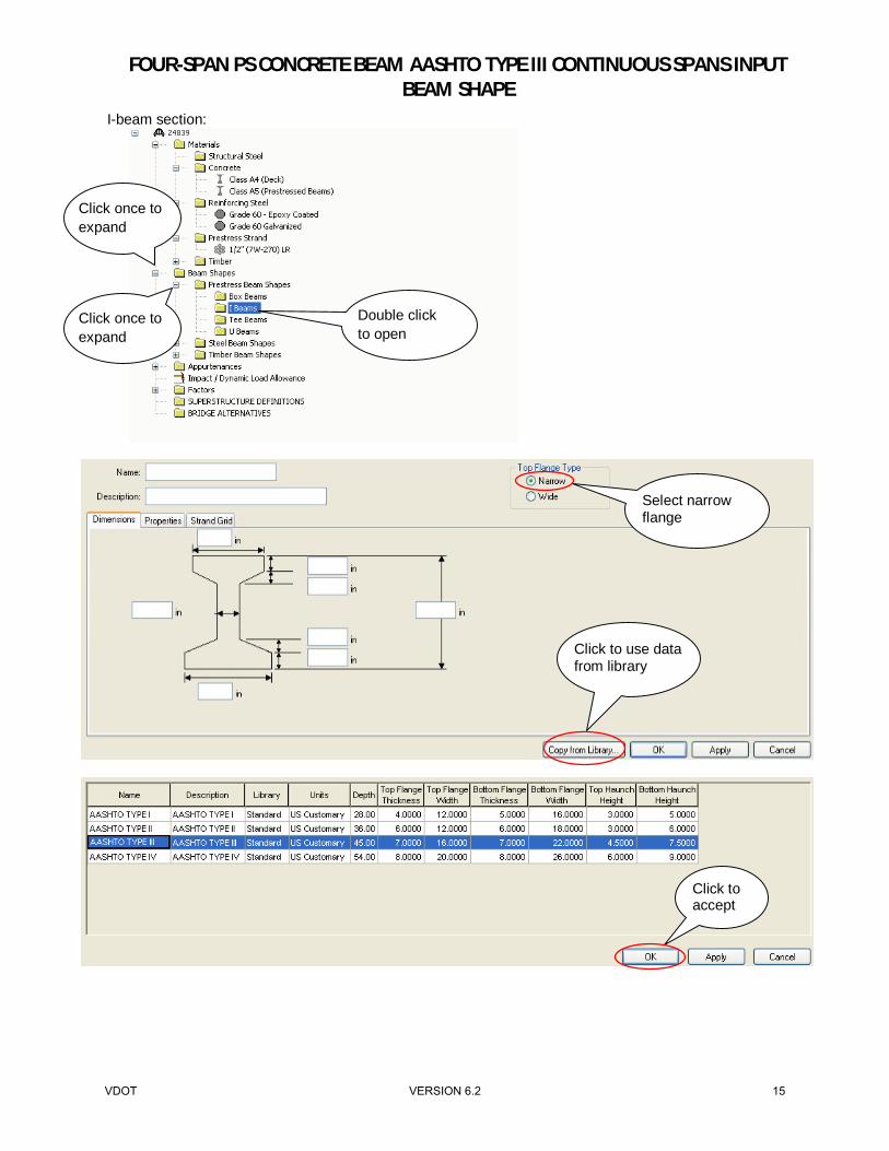
I-beam section:
Double click to open
Click once to expand
Click once to expand
Click to use data from library
Select narrow flange
Click to accept
VDOT VERSION 6.2 15

FOUR-SPAN PS CONCRETE BEAM AASHTO TYPE III CONTINUOUS SPANS INPUT BEAM SHAPE
Click to accept and close
Strand pattern can be modified using this tab
VDOT VERSION 6.2 16
FOUR-SPAN PS CONCRETE BEAM AASHTO TYPE III CONTINUOUS SPANS INPUT PARAPET
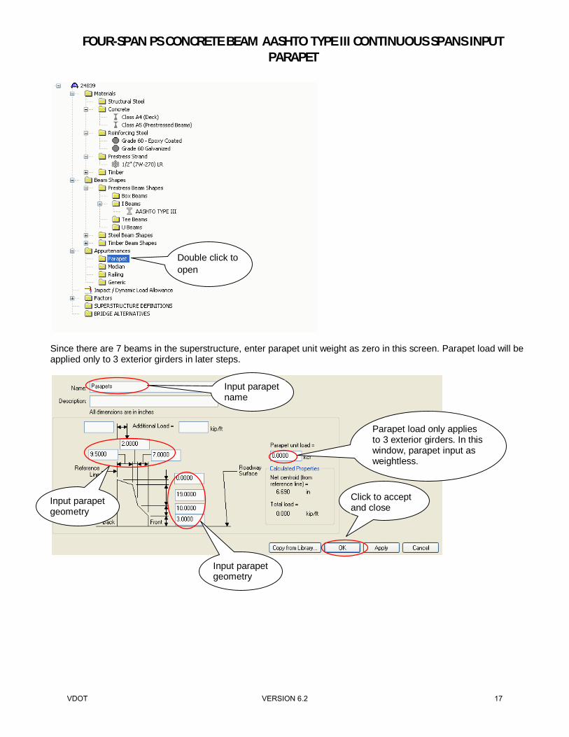
Since there are 7 beams in the superstructure, enter parapet unit weight as zero in this screen. Parapet load will be applied only to 3 exterior girders in later steps.
Click to accept and close
Parapet load only applies to 3 exterior girders. In this window, parapet input as weightless.
Input parapet name
Input parapet geometry
Input parapet geometry
Double click to open
VDOT VERSION 6.2 17

FOUR-SPAN PS CONCRETE BEAM AASHTO TYPE III CONTINUOUS SPANS INPUT IMPACT AND FACTORS
Impact/Dynamic Load Allowance:
Factors:
Click to accept and close
AASHTO LRFD Default
Double click to open
Double click to open
VDOT VERSION 6.2 18

FOUR-SPAN PS CONCRETE BEAM AASHTO TYPE III CONTINUOUS SPANS INPUT IMPACT AND FACTORS
Note: It is strongly recommended that the bridge data be saved at this point.
Click to use data from library
Click to accept
Click to accept and close
You can open to review the factors for different materials. No modification is needed.
VDOT VERSION 6.2 19

FOUR-SPAN PS CONCRETE BEAM AASHTO TYPE III CONTINUOUS SPANS INPUT SUPERSTRUCTURE DEFINITION
Superstructure Definition:
A girder system defines a set of girders within a cross section, including each girder’s relationship to the others. In this example, the bridge is continuous for Spans A to D and it is defined as one superstructure definition. For PS Concrete Bridges, some of the lengths are defined based on CL to CL of bearings (full model) and some of the lengths are defined based on end to end of the PS beams (beam model). For further clarification, following is the instruction from Virtis Manual:
Double click to open
Click to accept and close
VDOT VERSION 6.2 20

FOUR-SPAN PS CONCRETE BEAM AASHTO TYPE III CONTINUOUS SPANS INPUT SUPERSTRUCTURE DEFINITION
VDOT VERSION 6.2 21

FOUR-SPAN PS CONCRETE BEAM AASHTO TYPE III CONTINUOUS SPANS INPUT SUPERSTRUCTURE DEFINITION
Although only 2 decimal places will be displayed, enter length = 63.8333 for span 1 and 4. Note that the summation of the lengths entered is 257.6666 ft.
4 continuous spans in this superstructure unit
Override LRFR factors
Click to accept and close
Click to apply the changes
CL start bearing to CL Pier, CL pier to CL pier, CL pier to CL end bearing
Do not check (for illustration only)
VDOT VERSION 6.2 22

FOUR-SPAN PS CONCRETE BEAM AASHTO TYPE III CONTINUOUS SPANS INPUT SUPERSTRUCTURE DEFINITION
Factor override: Allows you to override the System Defaults library factors with a set of factors that have been entered for this bridge only. Factor override will remain when files are imported into future versions of Virtis. Unless factors specific to the bridge are required, overrides are not recommended as they can prevent updates to System Defaults in future versions (e.g legal load SHV factors in the MBE). Do not check the LRFR Factor Override which is shown checked above for illustration purposes only. Consider structural slab thickness for rating: Check this box if the structural slab thickness should be used to compute section properties for rating. If this box is not checked, the rating will use section properties computed from the total deck thickness. Consider wearing surface for rating: Check this box if the wearing surface loads should be included for rating.
Add Default Load Case Descriptions button: Adds four default load cases to the load case description table as shown above. The default load cases include dead load (DC) acting on non-composite section, dead load (DC) acting on long term composite section, dead load (DW) acting on long term composite section and stay-in-place forms acting on non-composite section. These default load cases can be edited and modified as desired.
Double click to open
Click to use default loads
Click to apply the changes
VDOT VERSION 6.2 23

FOUR-SPAN PS CONCRETE BEAM AASHTO TYPE III CONTINUOUS SPANS INPUT SUPERSTRUCTURE DEFINITION
Framing Plan Detail:
Double click to open
Input skew, clockwise skew is positive Input girder
spacing
Click to accept and close
Default loads modified in this example
Click to apply the changes
VDOT VERSION 6.2 24

FOUR-SPAN PS CONCRETE BEAM AASHTO TYPE III CONTINUOUS SPANS INPUT SUPERSTRUCTURE DEFINITION
Girder spacing orientation: Specify the girder spacing orientation for the girder spacing table as either perpendicular to girder or along support. If the girder spacing vary along the length of the bridge (that is, if the girders are not parallel to one another), then you must specify the girder spacing orientation as along support. Note that there is a limitation on using flared beams in girder system in Virtis.
This example has no skew. Additional options are available for skewed bridges, as shown below.
VDOT VERSION 6.2 25

FOUR-SPAN PS CONCRETE BEAM AASHTO TYPE III CONTINUOUS SPANS INPUT SUPERSTRUCTURE DEFINITION
See MathCAD calculations on page 101
VDOT VERSION 6.2 26

FOUR-SPAN PS CONCRETE BEAM AASHTO TYPE III CONTINUOUS SPANS INPUT SUPERSTRUCTURE DEFINITION
In this example, diaphragms were generated using “Diaphragm Wizard”. For more complex geometry, diaphragms can be input manually. Structure Typical Section:
Double click to open
Click to accept and close
VDOT VERSION 6.2 27

FOUR-SPAN PS CONCRETE BEAM AASHTO TYPE III CONTINUOUS SPANS INPUT SUPERSTRUCTURE DEFINITION
Enter fields as shown:
Although only 2 decimal places will be displayed, enter start/end distances of 24.917 and 3.167 ft.
Although only 2 decimal places will be displayed, enter start/end distances of 0.125 ft.
Click to apply the changes
Click to apply the changes
Click to apply the changes Click to add
new line or duplicate a line
VDOT VERSION 6.2 28

FOUR-SPAN PS CONCRETE BEAM AASHTO TYPE III CONTINUOUS SPANS INPUT SUPERSTRUCTURE DEFINITION
Compute button: Opens the Compute Lane Positions window, which presents the computed values in the lane position table based on information that you have entered using the other tabs of the Structure Typical Section window.
Apply button will populate the computed values for Lane Position.
Click to compute
Click to apply
Click to apply the changes
VDOT VERSION 6.2 29

FOUR-SPAN PS CONCRETE BEAM AASHTO TYPE III CONTINUOUS SPANS INPUT SUPERSTRUCTURE DEFINITION
Note: It is strongly recommended that the bridge data be saved at this point. To access the Structure Typical Section view, your structure typical section must be highlighted in the Bridge Workspace tree. Once structure typical section is highlighted, schematic view can be accessed by selecting “View Schematic”. This option is also available in toolbar under “Bridge Menu” or by right clicking on “Structure Typical Section”.
This example does not have wearing surface
Click to accept and close
Click on View Schematic
Highlight Structure Typical Section
Note that unit is lbs. per cubic foot
VDOT VERSION 6.2 30

FOUR-SPAN PS CONCRETE BEAM AASHTO TYPE III CONTINUOUS SPANS INPUT SUPERSTRUCTURE DEFINITION
Review and verify bridge typical section.
Click here to close the screen
VDOT VERSION 6.2 31

FOUR-SPAN PS CONCRETE BEAM AASHTO TYPE III CONTINUOUS SPANS INPUT SUPERSTRUCTURE DEFINITION
To access the Framing Plan view, your framing plan detail must be highlighted in the Bridge Workspace tree. Once framing plan detail is highlighted, schematic view can be accessed by selecting “View Schematic”. This option is also available in toolbar under “Bridge Menu” or by right clicking on “Framing Plan Detail”.
Review and verify bridge framing plan.
Click on View Schematic
Highlight Framing Plan Detail
Click here to close the screen
VDOT VERSION 6.2 32

FOUR-SPAN PS CONCRETE BEAM AASHTO TYPE III CONTINUOUS SPANS INPUT SUPERSTRUCTURE DEFINITION
Stress Limits:
Double click to open
Select Class A5 for PS Beams
Program calculates stress limits
Click to accept and close
VDOT VERSION 6.2 33
FOUR-SPAN PS CONCRETE BEAM AASHTO TYPE III CONTINUOUS SPANS INPUT SUPERSTRUCTURE DEFINITION
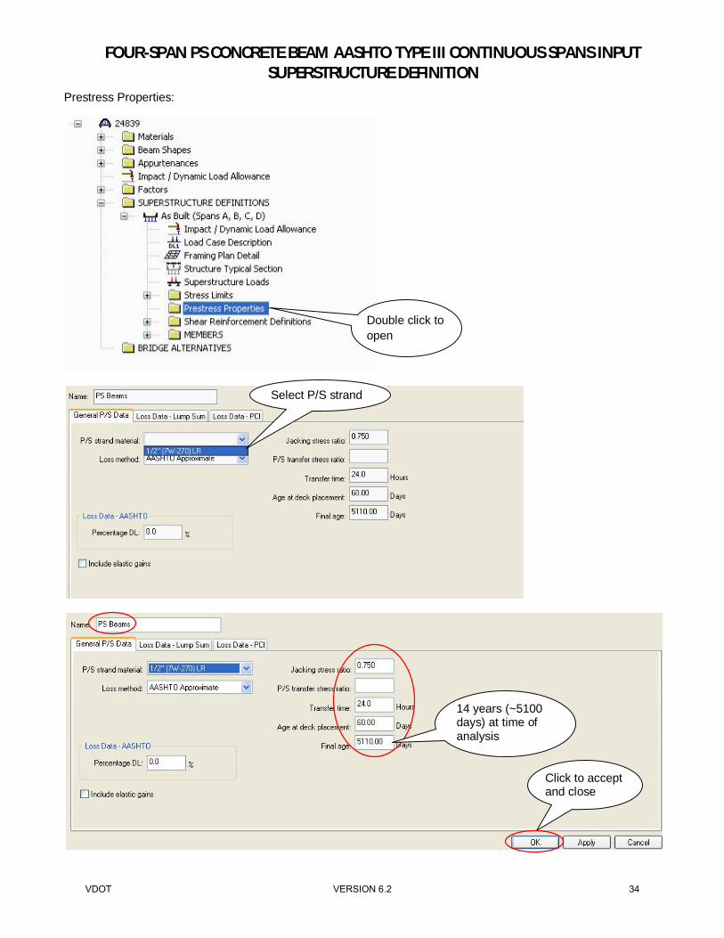
Prestress Properties:
Double click to open
Select P/S strand
Click to accept and close
14 years (~5100 days) at time of analysis
VDOT VERSION 6.2 34

FOUR-SPAN PS CONCRETE BEAM AASHTO TYPE III CONTINUOUS SPANS INPUT SUPERSTRUCTURE DEFINITION
Shear Reinforcement:
Double click to open
Click to accept and close
VDOT VERSION 6.2 35

FOUR-SPAN PS CONCRETE BEAM AASHTO TYPE III CONTINUOUS SPANS INPUT G1 INPUT
Members:
Existing: Check the box next to the name of the member alternative that represents the existing member. The existing member alternative is selected for analysis during a batch analysis process. Once the Bridge Alternative is created later in the example, a line of data will be shown with Existing checked. Current: Check the box next to the name of the member alternative that represents the current alternative being modified or reviewed. Once the Bridge Alternative is created later in the example, a line of data will be shown with Current checked. Span Length: This input is disabled for girder system since the span lengths are computed based on the data entered in the Structure Framing Plan Details and Structure Typical Section windows. Pedestrian Load: Enter the pedestrian live load acting on the member, in units of force per length of member.
Double click to open
Click to accept and close
VDOT VERSION 6.2 36

FOUR-SPAN PS CONCRETE BEAM AASHTO TYPE III CONTINUOUS SPANS INPUT G1 INPUT
Member Loads:
Double click to open
Select DC1 to add additional deck weight at overhang Click to add
load
Input additional overhang deck DL (see MathCAD calcs.)
Click to apply the load
VDOT VERSION 6.2 37
FOUR-SPAN PS CONCRETE BEAM AASHTO TYPE III CONTINUOUS SPANS INPUT G1 INPUT
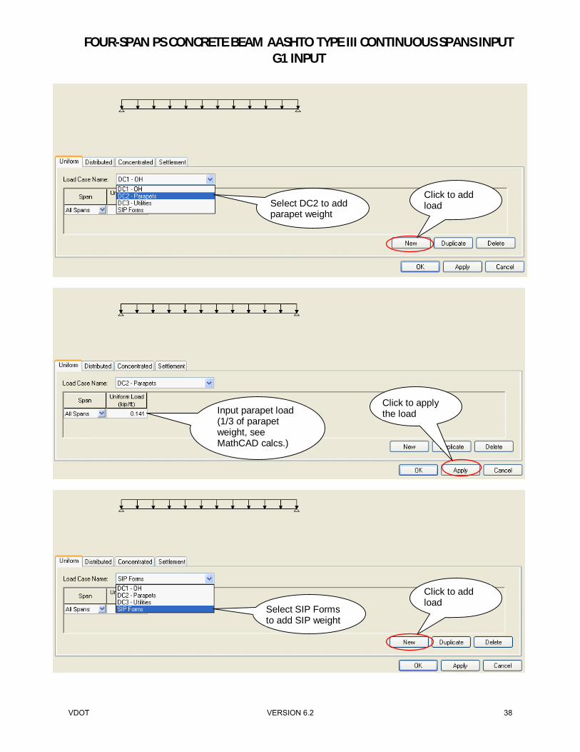
Select DC2 to add parapet weight
Click to add load
Input parapet load (1/3 of parapet weight, see MathCAD calcs.)
Click to apply the load
Select SIP Forms to add SIP weight
Click to add load
VDOT VERSION 6.2 38

FOUR-SPAN PS CONCRETE BEAM AASHTO TYPE III CONTINUOUS SPANS INPUT G1 INPUT
G1 has no utility load. Follow similar procedure for girders adjacent to utilities. Load for G2 to G7: Repeat the same steps and input DC1, DC2, DC3 and SIP Form loads for all other beams. See MathCAD calculations for interior and exterior loads. Note that G4 does not have parapet load. Utility load for G4, G5, G6 and G7 are different and other girders do not have utility load. Self-weight for deck and PS concrete beams will be calculated by program. Concrete diaphragm weight was entered previously in framing plan. See Load Summary below. Note: It is strongly recommended that the bridge data be saved at this point. Load Summary: Supports: G1: Entry shown previously – Overhang=0.016,
Parapet=0.141, SIP Form=0.072 G2: Parapet=0.141, SIP Form=0.145 G3: Parapet=0.141, SIP Form=0.145 G4: SIP Form=0.145, Utility=0.005 G5: Parapet=0.141, SIP Form=0.145, Utility=0.1025 G6: Parapet=0.141, SIP Form=0.145, Utility=0.1275 G7: Parapet=0.141, SIP Form=0.072, Utility=0.030, Overhang=0.016
Input SIP Form weight (see MathCAD calcs.)
Click to accept and close
Double click to open
VDOT VERSION 6.2 39

FOUR-SPAN PS CONCRETE BEAM AASHTO TYPE III CONTINUOUS SPANS INPUT G1 INPUT
Support Type: Select the support types as either pinned, roller, fixed, free, or other. Check marks will automatically appear in the appropriate boxes for translation and rotation constraints to correspond with the selected support type. Support Type for G2 to G7: Repeat the same step and input support type for all other beams.
Click to accept and close
Double click to open
VDOT VERSION 6.2 40

FOUR-SPAN PS CONCRETE BEAM AASHTO TYPE III CONTINUOUS SPANS INPUT G1 INPUT
Material Type: Select the material type. Virtis/Opis currently limits floorbeam and stringer definitions to steel beams. Girder Type: Select the girder type. The girder types available are dependent upon the selected material type.
Default rating method: Select the default rating method to be used for the member alternative.
Click to apply the changes
For PS beam, only option is schedule based
VDOT VERSION 6.2 41

FOUR-SPAN PS CONCRETE BEAM AASHTO TYPE III CONTINUOUS SPANS INPUT G1 INPUT
Default Materials:
Based on AASHTO MBE 6A.5.9, shear should be evaluated for permit loads.
Click to accept and close
Double click to open
VDOT VERSION 6.2 42

FOUR-SPAN PS CONCRETE BEAM AASHTO TYPE III CONTINUOUS SPANS INPUT G1 INPUT
Live Load Distribution:
Click to accept and close
Virtis does not have the beam information to generate Live Load Distribution at this stage. Skip this item for now.
VDOT VERSION 6.2 43

FOUR-SPAN PS CONCRETE BEAM AASHTO TYPE III CONTINUOUS SPANS INPUT G1 INPUT
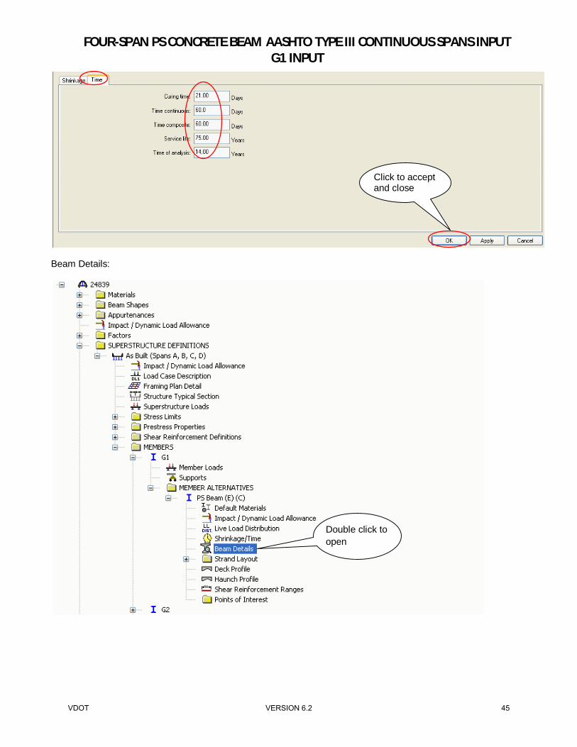
Shrinkage/Time:
Double click to open
Click to apply the changes
VDOT VERSION 6.2 44
FOUR-SPAN PS CONCRETE BEAM AASHTO TYPE III CONTINUOUS SPANS INPUT G1 INPUT
Beam Details:
Click to accept and close
Double click to open
VDOT VERSION 6.2 45

FOUR-SPAN PS CONCRETE BEAM AASHTO TYPE III CONTINUOUS SPANS INPUT G1 INPUT
Although only 2 decimal places will be displayed, enter length = 64.2083 ft. for spans 1 and 4.
Click to apply the changes
End of the beam to CL bearings
See MathCAD calculations
Beam length (end to end). This length has to be exact with all digits.
CL bearing to CL pier
Click to apply the changes
Click to apply the changes
Click to add a line
VDOT VERSION 6.2 46

FOUR-SPAN PS CONCRETE BEAM AASHTO TYPE III CONTINUOUS SPANS INPUT G1 INPUT
Click to apply the changes
Virtis computes for intentionally roughened
Enter continuity reinforcement
Click to accept and close
VDOT VERSION 6.2 47

FOUR-SPAN PS CONCRETE BEAM AASHTO TYPE III CONTINUOUS SPANS INPUT G1 INPUT
Strand Layout:
Double click to open
By clicking on each location, select strands at mid-span based on PS concrete beam
VDOT VERSION 6.2 48

FOUR-SPAN PS CONCRETE BEAM AASHTO TYPE III CONTINUOUS SPANS INPUT G1 INPUT
Strands pattern at mid-span
Verify total number of strands
Length from end of the beam to harp point
Uncheck this since beam is not symmetric
VDOT VERSION 6.2 49

FOUR-SPAN PS CONCRETE BEAM AASHTO TYPE III CONTINUOUS SPANS INPUT G1 INPUT
Note: For span 1, harp point is not at symmetrical distance, so harped strand location needs to be entered for both left and right end. For spans 2 and 3, harp point is at symmetrical distance of 25.50 (use Symmetry check box). Span 4 is not symmetrical and 25.583 should be entered for left and 25.625 for right (opposite distance entries from span 1). Enter the harped strand locations for both left and right ends for span 4. Strand patterns are the same for all beams. A and D (Spans 1 and 4): Distance = 62.5 / 2 – 6.5 + 10.5 / 12 = 25.625 ft. = 62.5 / 2 – 6.5 + 10 / 12 = 25.583 ft. B and C (Spans 2 and 3): Distance = 62.333 / 2 – 6.5 + 10 / 12 = 25.50 ft.
By clicking on each location, select harped strands at end of the beam based on PS concrete beam
Select left end to input harped strand location
Click to accept and close
VDOT VERSION 6.2 50

FOUR-SPAN PS CONCRETE BEAM AASHTO TYPE III CONTINUOUS SPANS INPUT G1 INPUT
Note: Since G2 (interior girder) is not entered yet, Virtis cannot generate deck profile for G1 at this point. Deck profile for G1 will be generated in next steps, after inputting G2.
Double click on Span 2, 3 and 4 and repeat the same steps to define strand patterns for all 4 spans
VDOT VERSION 6.2 51

FOUR-SPAN PS CONCRETE BEAM AASHTO TYPE III CONTINUOUS SPANS INPUT G1 INPUT
Haunch Profile:
Double click to open
Click to add a line
VDOT VERSION 6.2 52

FOUR-SPAN PS CONCRETE BEAM AASHTO TYPE III CONTINUOUS SPANS INPUT G1 INPUT
Although only 2 decimal places will be displayed, enter length = 257.6666 ft. Shear Reinforcement Ranges:
Click to accept and close
Double click to open
Click to add a line or duplicate
VDOT VERSION 6.2 53

FOUR-SPAN PS CONCRETE BEAM AASHTO TYPE III CONTINUOUS SPANS INPUT G1 INPUT
If two or more spans are identical or similar, stirrup data may be copied to another span using the “Copy to Span” button and selecting new span number. The stirrup data may be edited for the new span if the two spans are not identical. The ranges of Shear Reinforcement must be defined in this tab over the entire the length of the PS Concrete Beam in each span.
Input stirrups location
Click to apply then enter data for next span
Reinforcement must be entered for each span
VDOT VERSION 6.2 54

FOUR-SPAN PS CONCRETE BEAM AASHTO TYPE III CONTINUOUS SPANS INPUT G1 INPUT
Since Shear Reinforcement is identical in Span 2 and 3, copy Span 2 to Span 3 as follows:
Click to apply then enter data for next span
Input stirrups location for Span 2
Click Copy to Span
Select Span 3
Click to apply then enter data for next span
VDOT VERSION 6.2 55

FOUR-SPAN PS CONCRETE BEAM AASHTO TYPE III CONTINUOUS SPANS INPUT G1 INPUT
At this point beam information for G1 is complete and Virtis will be able to generate Standard Live Load Distribution Factors.
Input stirrups location for Span 4
Click to accept and close
VDOT VERSION 6.2 56

FOUR-SPAN PS CONCRETE BEAM AASHTO TYPE III CONTINUOUS SPANS INPUT G1 INPUT
Live Load Distribution:
Compute from Typical Section button: Computes the live load distribution factors per wheel based on the values that you entered in the Structure Typical Section window and the Structure Framing Plan Details window. The computed distribution factors are then displayed on this tab.
Double click to open
Click to compute
VDOT VERSION 6.2 57

FOUR-SPAN PS CONCRETE BEAM AASHTO TYPE III CONTINUOUS SPANS INPUT G1 INPUT
Note: Standard Distribution Factors for LFR were created. However, since G2 (interior girder) is not input yet, Virtis cannot generate LRFD Live Load Distribution Factors for G1 at this point. LRFD Live Load Distribution Factors for G1 will be generated in next steps, after inputting G2. To access the PS Beam view, your member alternative must be highlighted in the Bridge Workspace tree. Once PS Beam is highlighted, schematic view can be accessed by selecting “View Schematic”. This option is also available in toolbar under “Bridge Menu” or by right clicking on “PS Beam”.
Click on View Schematic
Highlight member alternative
Click to accept and close
VDOT VERSION 6.2 58

FOUR-SPAN PS CONCRETE BEAM AASHTO TYPE III CONTINUOUS SPANS INPUT G1 INPUT
Note: It is strongly recommended that the bridge data be saved at this point.
Click here to close the screen
Click here to change the zoom
VDOT VERSION 6.2 59

FOUR-SPAN PS CONCRETE BEAM AASHTO TYPE III CONTINUOUS SPANS INPUT LINKING GIRDERS
Link with: Select the member to which this member is to be linked. If two members are linked, they share the same definition and any revisions to one member affect the other member. If the applied loads acting on the two members are different (due to different tributary width, different arrangements of parapets, medians, sidewalk, the railings, and different lane positions), then they should not be linked with one another. If you do not want to link this member with any other member, select “None”. This input field is available for girder system only. G3 is identical to G2 so it can be linked to G2 as shown below:
If a warning box pops up, click to confirm.
Double click to open
VDOT VERSION 6.2 60

FOUR-SPAN PS CONCRETE BEAM AASHTO TYPE III CONTINUOUS SPANS INPUT LINKING GIRDERS
Note: It is strongly recommended that the bridge data be saved at this point.
Click to accept and close
G3 is linked to G2
VDOT VERSION 6.2 61

FOUR-SPAN PS CONCRETE BEAM AASHTO TYPE III CONTINUOUS SPANS INPUT G2 INPUT
Copy Properties: Since most girder detail and properties are similar between interior and exterior girders of this bridge, you can copy properties of one girder to another as shown below:
Right click on G1 and choose Copy.
VDOT VERSION 6.2 62

FOUR-SPAN PS CONCRETE BEAM AASHTO TYPE III CONTINUOUS SPANS INPUT G2 INPUT
Right click on Member Alternative for G2 and paste. You will notice that a copy of G1 is placed under G2 Member Alternative. Double click to open it.
After copying and pasting exterior beam to interior, the following items need to be updated in interior beam:
- Live Load Distribution Factors (Standard and LRFD) - Deck Profile - Haunch Profile - Beam details and strand layout (if interior and exterior beams are different)
Click to accept and close
Remove “copy of”
Double click to open
VDOT VERSION 6.2 63

FOUR-SPAN PS CONCRETE BEAM AASHTO TYPE III CONTINUOUS SPANS INPUT G2 INPUT
Click to re-compute
Click to apply the changes
VDOT VERSION 6.2 64

FOUR-SPAN PS CONCRETE BEAM AASHTO TYPE III CONTINUOUS SPANS INPUT G2 INPUT
Click to compute
Virtis generates Live Load Distribution Factors
VDOT VERSION 6.2 65

FOUR-SPAN PS CONCRETE BEAM AASHTO TYPE III CONTINUOUS SPANS INPUT G2 INPUT
Double click to open
Click to compute
Click here to review deflection, moment and shear distribution factors
Click to accept and close
VDOT VERSION 6.2 66

FOUR-SPAN PS CONCRETE BEAM AASHTO TYPE III CONTINUOUS SPANS INPUT G2 INPUT
½” deck thickness considered non-structural
If there is an error, manually input effective width
Click apply to accept
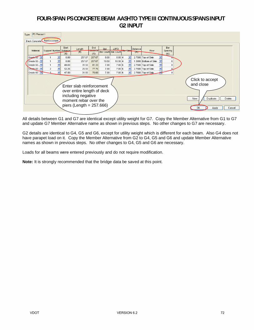
Enter slab reinforcement over entire length of deck including negative moment rebar over the piers (Length = 257.666)
Click to accept and close
VDOT VERSION 6.2 67

FOUR-SPAN PS CONCRETE BEAM AASHTO TYPE III CONTINUOUS SPANS INPUT G2 INPUT
At this point, G2 is entered and Virtis can generate LRFD Live Load Distribution for G1:
Double click to open
Click to accept and close
Double click to open
VDOT VERSION 6.2 68

FOUR-SPAN PS CONCRETE BEAM AASHTO TYPE III CONTINUOUS SPANS INPUT G2 INPUT
Virtis generates Live Load Distribution Factors
Click to compute
VDOT VERSION 6.2 69

FOUR-SPAN PS CONCRETE BEAM AASHTO TYPE III CONTINUOUS SPANS INPUT G2 INPUT
At this point, G2 is entered and Virtis can generate Deck Profile for G1:
Click here to review deflection, moment and shear distribution factors
Click to accept and close
Double click to open
VDOT VERSION 6.2 70

FOUR-SPAN PS CONCRETE BEAM AASHTO TYPE III CONTINUOUS SPANS INPUT G2 INPUT
Click to compute
½” deck thickness considered non-structural
If there is an error, manually input effective width based on bridge typical section Click apply to
accept
VDOT VERSION 6.2 71
FOUR-SPAN PS CONCRETE BEAM AASHTO TYPE III CONTINUOUS SPANS INPUT G2 INPUT
All details between G1 and G7 are identical except utility weight for G7. Copy the Member Alternative from G1 to G7 and update G7 Member Alternative name as shown in previous steps. No other changes to G7 are necessary. G2 details are identical to G4, G5 and G6, except for utility weight which is different for each beam. Also G4 does not have parapet load on it. Copy the Member Alternative from G2 to G4, G5 and G6 and update Member Alternative names as shown in previous steps. No other changes to G4, G5 and G6 are necessary. Loads for all beams were entered previously and do not require modification. Note: It is strongly recommended that the bridge data be saved at this point.
Click to accept and close Enter slab reinforcement
over entire length of deck including negative moment rebar over the piers (Length = 257.666)
VDOT VERSION 6.2 72

FOUR-SPAN PS CONCRETE BEAM AASHTO TYPE III CONTINUOUS SPANS INPUT BRIDGE ALTERNATIVE
A bridge can have several unique bridge alternatives. Each bridge alternative must include the entire bridge but can consist of different layout of superstructures. The number of spans, the span lengths, and the pier locations are defined within the bridge alternative (and its accompanying windows). Entering different alternatives can be useful when comparing various alternatives for a preliminary study.
The Description tab of bridge Alternative window allows you to describe the orientation of the bridge alternative reference line with respect to the bridge global reference point. You can generate the bridge alternative using the Superstructure wizard or manually enter the require information. This data is more for information purpose than for calculations. In this example, Superstructure wizard was used as shown below:
Double click to open
Click here
VDOT VERSION 6.2 73

FOUR-SPAN PS CONCRETE BEAM AASHTO TYPE III CONTINUOUS SPANS INPUT BRIDGE ALTERNATIVE
In this example there is one superstructure defined consisting of four spans (A, B, C, D). For additional superstructures, clicking generate superstructure names will populate each superstructure line.
Input number of superstructures
Click to finish
Verify correct superstructure definition is selected
Input name of superstructure
Click to populate superstructure names
VDOT VERSION 6.2 74

FOUR-SPAN PS CONCRETE BEAM AASHTO TYPE III CONTINUOUS SPANS INPUT BRIDGE ALTERNATIVE
Bridge alternative for 1 continuous unit of 4 spans
Click to accept and close
Right click on Bridge Alternatives and select Expand Branch
VDOT VERSION 6.2 75

FOUR-SPAN PS CONCRETE BEAM AASHTO TYPE III CONTINUOUS SPANS INPUT BRIDGE ALTERNATIVE
Before continuing, save your work and check the input.
Click to save
Make sure there is no error
Click to save
Review error and warning messages
VDOT VERSION 6.2 76

FOUR-SPAN PS CONCRETE BEAM AASHTO TYPE III CONTINUOUS SPANS INPUT BRIDGE ALTERNATIVE
To export the XML file to hard drive or server, click on file\export.
VDOT VERSION 6.2 77

FOUR-SPAN PS CONCRETE BEAM AASHTO TYPE III CONTINUOUS SPANS INPUT RATING BRIDGE AND REVIEW THE OUTPUT
Rating the bridge, reviewing the results and output: Click on “View analysis setting” to select vehicles for ratings.
Notice the changes under Vehicle Selection and Vehicle Summary after Rating Method is changed from LFD to LRFR shown in the screenshot on the following page. Note, if using the current VDOT library, VA Semi was changed to VA Type 3S2 and VA Single was changed to VA Type 3.
Set the Rating Method to LRFR
VA Semi is similar to VA Type 3S2 and VA Single is similar to VA Type 3
VDOT VERSION 6.2 78

FOUR-SPAN PS CONCRETE BEAM AASHTO TYPE III CONTINUOUS SPANS INPUT RATING BRIDGE AND REVIEW THE OUTPUT
Select the following trucks for “continuous” bridge rating. Since span lengths are less than 200’, Legal Lane Load is not required for rating. There is a limit on number of vehicles that can be listed for an analysis run in Virtis so the continuous vehicles have been split into 2 separate analysis runs. Continuous 1
VDOT VERSION 6.2 79

FOUR-SPAN PS CONCRETE BEAM AASHTO TYPE III CONTINUOUS SPANS INPUT RATING BRIDGE AND REVIEW THE OUTPUT
Continuous 2
VDOT VERSION 6.2 80

FOUR-SPAN PS CONCRETE BEAM AASHTO TYPE III CONTINUOUS SPANS INPUT RATING BRIDGE AND REVIEW THE OUTPUT
For Continuous 1 analysis run
Click on Advanced
Make sure lane type legal load has legal pair checked
VDOT VERSION 6.2 81

FOUR-SPAN PS CONCRETE BEAM AASHTO TYPE III CONTINUOUS SPANS INPUT RATING BRIDGE AND REVIEW THE OUTPUT
For Continuous 2 analysis run
Make sure permit loads are set with unlimited crossing mixed with traffic
Click on Advanced
VDOT VERSION 6.2 82

FOUR-SPAN PS CONCRETE BEAM AASHTO TYPE III CONTINUOUS SPANS INPUT RATING BRIDGE AND REVIEW THE OUTPUT
For each analysis run, to review the reactions and specification checks, make sure all items are checked in output menu.
Click on Analyze button to start the analysis to rate individual girders in “Bridge Workspace”:
Select to analyze all girders
Click to accept and close
VDOT VERSION 6.2 83

FOUR-SPAN PS CONCRETE BEAM AASHTO TYPE III CONTINUOUS SPANS INPUT RATING BRIDGE AND REVIEW THE OUTPUT
Analysis can be done from the top for the whole structures as shown above or from the member folder for each individual girder as shown below. Simply select and click Analyze button to start. In this example, Continuous 1 set of trucks were selected.
Select for one girder rating
VDOT VERSION 6.2 84

FOUR-SPAN PS CONCRETE BEAM AASHTO TYPE III CONTINUOUS SPANS INPUT RATING BRIDGE AND REVIEW THE OUTPUT
To review the result, select the girder and click on View analysis report icon.
Click to close
Step 1: Select one girder
Step 2: Click to review results
VDOT VERSION 6.2 85
FOUR-SPAN PS CONCRETE BEAM AASHTO TYPE III CONTINUOUS SPANS INPUT RATING BRIDGE AND REVIEW THE OUTPUT
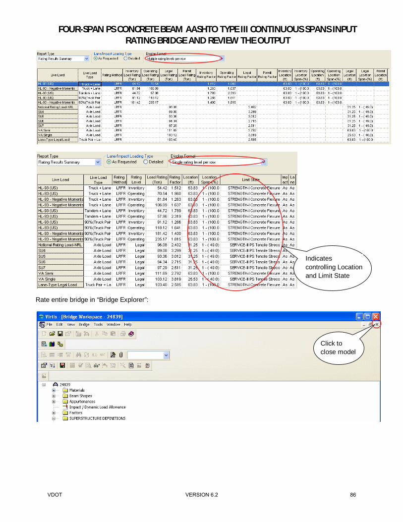
Rate entire bridge in “Bridge Explorer”:
Click to close model
Indicates controlling Location and Limit State
VDOT VERSION 6.2 86

FOUR-SPAN PS CONCRETE BEAM AASHTO TYPE III CONTINUOUS SPANS INPUT RATING BRIDGE AND REVIEW THE OUTPUT
Select the bridge in “Bridge Explorer” and click “Rate”.
Step 2: Click on the bridge in explorer
Step 1: Select Bridge Explorer
Step 3: Click on Rate
VDOT VERSION 6.2 87

FOUR-SPAN PS CONCRETE BEAM AASHTO TYPE III CONTINUOUS SPANS INPUT RATING BRIDGE AND REVIEW THE OUTPUT
Select Continuous 1 analysis vehicles
When using this method to rate the entire bridge, a screenshot for the lowest ratings will show on the screen.
Click to accept and run
Click to close
VDOT VERSION 6.2 88

FOUR-SPAN PS CONCRETE BEAM AASHTO TYPE III CONTINUOUS SPANS INPUT RATING BRIDGE AND REVIEW THE OUTPUT
VDOT VERSION 6.2 89

FOUR-SPAN PS CONCRETE BEAM AASHTO TYPE III CONTINUOUS SPANS INPUT RATING BRIDGE AND REVIEW THE OUTPUT
Reviewing Output in Virtis. To review the output, calculations and specification checks, open the bridge and run all girders or one individual girder as shown in the previous steps. In this example G1 is analyzed.
Select for one girder rating
Click to apply the changes
VDOT VERSION 6.2 90

FOUR-SPAN PS CONCRETE BEAM AASHTO TYPE III CONTINUOUS SPANS INPUT RATING BRIDGE AND REVIEW THE OUTPUT
To review the reactions and specification checks, make sure all items are checked in output menu.
Click to accept and close
VDOT VERSION 6.2 91

FOUR-SPAN PS CONCRETE BEAM AASHTO TYPE III CONTINUOUS SPANS INPUT RATING BRIDGE AND REVIEW THE OUTPUT
Click on Analyze button to start the analysis.
VDOT VERSION 6.2 92

FOUR-SPAN PS CONCRETE BEAM AASHTO TYPE III CONTINUOUS SPANS INPUT RATING BRIDGE AND REVIEW THE OUTPUT
To review analysis charts, select girder and click on view analysis charts icon.
Click on view analysis charts to see moment, shear and deflection
You can select all or some of the vehicles and review moment, shear, axial and deflection
VDOT VERSION 6.2 93

FOUR-SPAN PS CONCRETE BEAM AASHTO TYPE III CONTINUOUS SPANS INPUT RATING BRIDGE AND REVIEW THE OUTPUT
To review specification check, select girder and click on view spec check icon.
Click on View Spec Check to see calculation details
Click to select
Click on each column to sort the results
VDOT VERSION 6.2 94

FOUR-SPAN PS CONCRETE BEAM AASHTO TYPE III CONTINUOUS SPANS INPUT RATING BRIDGE AND REVIEW THE OUTPUT
Click on Specification Reference column header to sort the column and scroll down to 5.7.3.2 Flexural Resistance to review moment capacity.
Click to select
Shows if item passed or failed
VDOT VERSION 6.2 95

FOUR-SPAN PS CONCRETE BEAM AASHTO TYPE III CONTINUOUS SPANS INPUT RATING BRIDGE AND REVIEW THE OUTPUT
Click OK to close.
VDOT VERSION 6.2 96

FOUR-SPAN PS CONCRETE BEAM AASHTO TYPE III CONTINUOUS SPANS INPUT RATING BRIDGE AND REVIEW THE OUTPUT
Rating factor for Flexure (scroll down to 6.4.2.1 concrete fleural general load rating equation)
Click to select
VDOT VERSION 6.2 97

FOUR-SPAN PS CONCRETE BEAM AASHTO TYPE III CONTINUOUS SPANS INPUT RATING BRIDGE AND REVIEW THE OUTPUT
Rating factor for PS Tensile Stress
Click to select
VDOT VERSION 6.2 98

FOUR-SPAN PS CONCRETE BEAM AASHTO TYPE III CONTINUOUS SPANS INPUT RATING BRIDGE AND REVIEW THE OUTPUT
To review the shear, scroll down to 5.8.3.3 Shear Resistance.
Click to select
VDOT VERSION 6.2 99

FOUR-SPAN PS CONCRETE BEAM AASHTO TYPE III CONTINUOUS SPANS INPUT RATING BRIDGE AND REVIEW THE OUTPUT
Rating factor for Shear (scroll down to 6.4.2.1 concrete shear general load rating equation)
Click to select
VDOT VERSION 6.2 100

Subject: Calculations for Bridge Load Rating Using Virtis
Structure ID: 24839 State Bridge No: 001-1001
Superstructure Definition (As-Built Spans A, B, C and D):
Framing Plan:Skew DMS 0 0, 0, ( ) 0 deg⋅=:=
Structure Typical Section:SpacingBay1to6 7ft 3in+ 7.25 ft=:=
Overhang 2ft:=
Member Alternatives:
kips 1000lb:=
Beam Details:
n
28500kips
in2
4463kips
in2
6.4=:=
Member Loads:SIP Form Weight:
wSIP 20lb
ft2:=
WSIP_Ext wSIPSpacingBay1to6
2⋅ 0.072
kipsft
⋅=:= On G1 & G7
WSIP_Int wSIP SpacingBay1to6⋅ 0.145kips
ft⋅=:= On G2 to G6
Additional deck overhang weight:
γc 150lb
ft3:=
wOH γc 3ft 2in+ 8in−( ) 0.5⋅ in[ ]⋅:=
wOH 0.016kips
ft⋅= Apply to G1 and G7
VDOT VERSION 6.2 101

Parapet weight:
A 2ft 8in+( ) 8in3in2
+⎛⎜⎝
⎞⎟⎠
⋅ 3in 9⋅ in+7in2
10⋅ in+2in 19⋅ in
2+ 2in 10⋅ in+:=
A 2.812 ft2=
wparapet A γc⋅:=
wparapet 0.422kips
ft⋅=
wparapet_per_beamwparapet
3:=
wparapet_per_beam 0.141kips
ft⋅= Apply to three exterior beams
Utility Weight:
Beam412
10⋅lbft
0.005kips
ft=:=
Beam512
10⋅lbft
12
195⋅lbft
+ 0.1025kips
ft=:=
Beam612
60⋅lbft
12
195⋅lbft
+ 0.1275kips
ft=:=
Beam712
60⋅lbft
0.03kips
ft=:=
VDOT VERSION 6.2 102

Diaphragm Weight (Intermediate):
7'-3"
3'-9"
1'-212"
Adiaphragm 17.64ft2:=
tdiaphragm 10in:=
Wdiaph Adiaphragm tdiaphragm⋅ γc⋅ 2.205 kips⋅=:=
Diaphragm Weight (End) :
7'-3"
3'-9"
Adiaphragm 23.75ft2:=
tdiaphragm 14in:=
Wdiaph Adiaphragm tdiaphragm⋅ γc⋅ 4.16 kips⋅=:=
VDOT VERSION 6.2 103

VDOT VERSION 6.2 104

VDOT VERSION 6.2 105

VDOT VERSION 6.2 106

VDOT VERSION 6.2 107

VDOT VERSION 6.2 108