free-air-3 - essencompany€¦ · be deemed to be an integral part of the manual, please contact...
TRANSCRIPT

Index 34AIssue 08.2016
Free-Air-3 Free cooling units48 V DC - 230 V AC / 1ph / 50Hz

2
F R E E-A I R -3
EN/08.2016/34A © STULZ SpA – all rights reserved
STULZ SpAVia Evangelista Torricelli n.337067 Valeggio sul Mincio VR
A B O U T S T U L Z G M B HSince it was founded in 1947, the STULZ company has evolved into one of the world’s leading system suppliers of air-conditioning technology. With the manufacture of precision air-conditioning units and chillers, the sale of air-conditioning and humidification systems and service and object management, this division of the STULZ Group achieved a turnover of around 370 million euros in 2014. Since 1974 the group has seen continual international expansion of its air conditioning technology business, spe-cialising in A/C for data centres and telecommunications installations. STULZ employs 2,200 workers in Germany and seventeen subsidiaries (in France, Italy, Great Britain, Belgium, Brazil, the Netherlands, New Zealand, Mexico, Austria, Poland, Spain, Singapore, China, India, South Africa, Australia and the USA). The company also co-op-erates with sales and service partners in over 130 other countries, and therefore boasts an international network of air-conditioning specialists. It has production plants in Germany, Italy, the USA, 2 in China, Brazil and India. The STULZ Group employs around 5,300 people worldwide, with current annual sales of around 950 million euros.
3
F R E E-A I R -3
EN/08.2016/34A © STULZ SpA – all rights reserved
Free-Air-3
Dear customer,
thank you for having chosen Free-Air-3 from STULZ.
It's the result of decades of research and design studies, with a fine search of materials and technologies to obtain an high quality unit.
The CE mark guarantees that the STULZ products satisfy the requirements of the European Machinery Directive for safety.
The level of quality is constantly checked at every stage, from design to production, making the STULZ products synonymous of SAFETY, QUALITY and RELIABILITY.
For general inquiries concerning products by STULZ SpA, please contact our Aftersales at:
telephone 0039 045 6331615
fax 0039 045 6331635
e-mail [email protected]
For further information concerning our products and services visit our website :
www.stulz.it
4
F R E E-A I R -3
EN/08.2016/34A © STULZ SpA – all rights reserved

5
F R E E-A I R -3
EN/08.2016/34A © STULZ SpA – all rights reserved
Table of contents1. Safety directions ...........................................................................................................7
1.1. Personnel qualification and training ...................................................................................................... 71.2. Danger in case of failure to comply with safety instructions ......................................................... 71.3. Work in safety ................................................................................................................................................ 71.4. Maintenance, inspection and monitoring of the plant ..................................................................... 81.5. Independent conversion and manufacture of replacement parts ............................................... 81.6. Unacceptable operating methods .......................................................................................................... 8
2. Unit identification ..........................................................................................................93. Components and operating principle ........................................................................12
3.1. Intended and non-intended use ............................................................................................................123.2. Component lay-out ....................................................................................................................................143.3. Working modes ...........................................................................................................................................143.4. Mechanical components ..........................................................................................................................153.5. Motors ............................................................................................................................................................153.6. Control, monitoring and safety components.....................................................................................15
4. Unpacking and inspection ..........................................................................................185. Installation ...................................................................................................................20
5.1. Positioning and mechanical installation..............................................................................................205.2. Electrical connections ..............................................................................................................................25
6. Start-up ........................................................................................................................276.1. Controller setting ........................................................................................................................................276.2. Functional checks ......................................................................................................................................276.3. Other tests (facultative) ............................................................................................................................286.4. Shutdown ......................................................................................................................................................28
7. Maintenance .................................................................................................................297.1. Safety instructions .....................................................................................................................................297.2. Preventative maintenance schedule ...................................................................................................297.3. Cleaning / replacement of components ............................................................................................307.4. General appliance cleaning procedures .............................................................................................30
8. Options .........................................................................................................................318.1. Aluminium casing – PAKAL ....................................................................................................................318.2. Stainless steel casing – PAKIN .............................................................................................................318.3. WIB1000 / WIB1485 ..............................................................................................................................31
9. Information on residual hazards and emergency situations ....................................319.1. General safety provisions ........................................................................................................................319.2. Hazards arising from the product coming into contact with things or persons ....................329.3. Hazards arising from electrical faults ..................................................................................................329.4. Fire hazards ..................................................................................................................................................339.5. Toxic substances ........................................................................................................................................33
10. Uninstalling and disposal of the unit........................................................................3411. Appendix: technical data ..........................................................................................35
6
F R E E-A I R -3
EN/08.2016/34A © STULZ SpA – all rights reserved
IMPORTANT
These operating instructions are to be read carefully and complied with before installing and operating the A/C unit.
Keep this manual for the whole life period of the unit, inside the shelter or together with any other literature concerning the equipment which utilizes the product, provided it is a dry and clean
place.
This manual reflects the state of the art existing at the time the product is marketed and shall not be deemed to be inadequate for the sole reason that it has not been updated as a result of any
new experience.
STULZ reserves the right to update the product and relevant manual without being required to update previous products and manuals other than in exceptional circumstances.
To require or receive any updates of the instructions manual or amendments thereto, which shall be deemed to be an integral part of the manual, please contact your local STULZ partner.
It is absolutely essential to comply with the measures listed in chapter "Safety directions".
7
F R E E-A I R -3
EN/08.2016/34A © STULZ SpA – all rights reserved
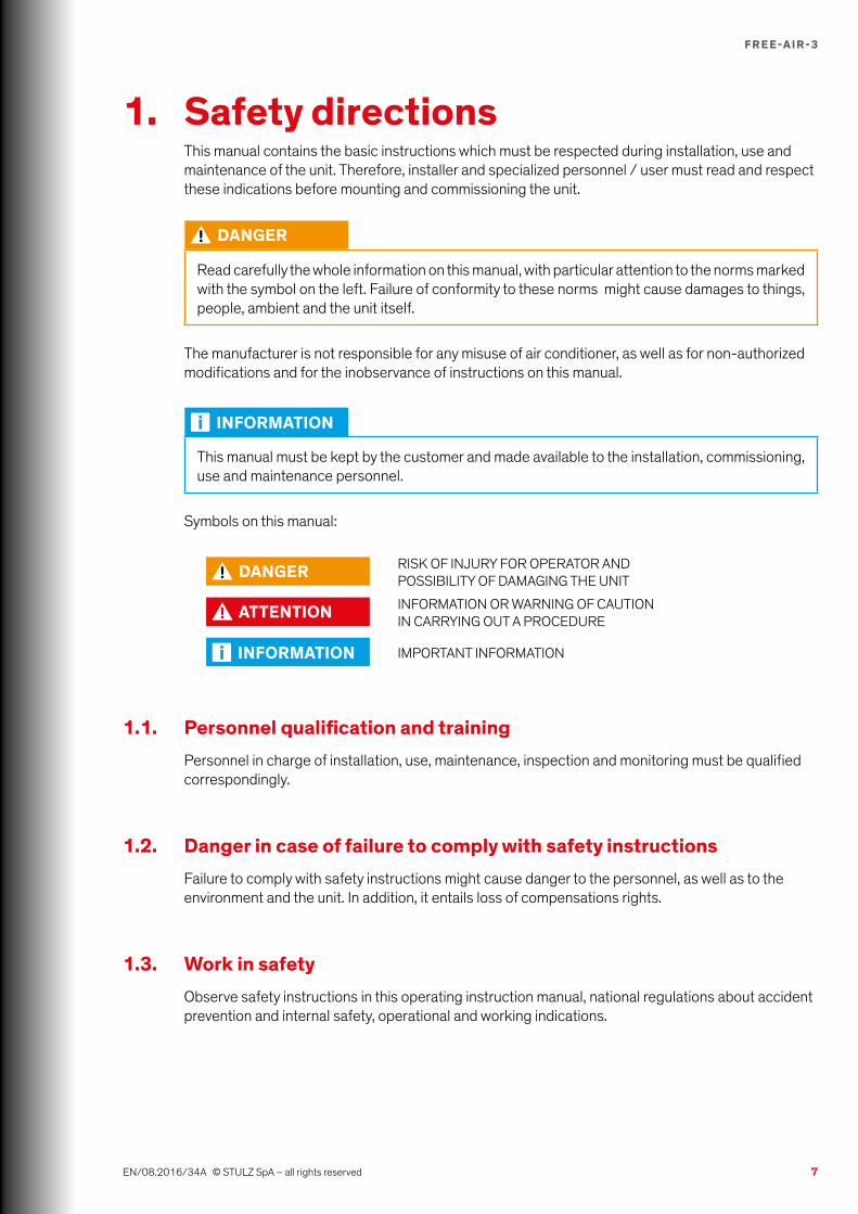
1. Safety directionsThis manual contains the basic instructions which must be respected during installation, use and maintenance of the unit. Therefore, installer and specialized personnel / user must read and respect these indications before mounting and commissioning the unit.
DANGER
Read carefully the whole information on this manual, with particular attention to the norms marked with the symbol on the left. Failure of conformity to these norms might cause damages to things, people, ambient and the unit itself.
The manufacturer is not responsible for any misuse of air conditioner, as well as for non-authorized modifications and for the inobservance of instructions on this manual.
INFORMATION
This manual must be kept by the customer and made available to the installation, commissioning, use and maintenance personnel.
Symbols on this manual:
DANGER RISK OF INJURY FOR OPERATOR AND POSSIBILITY OF DAMAGING THE UNIT
ATTENTION INFORMATION OR WARNING OF CAUTION IN CARRYING OUT A PROCEDURE
INFORMATION IMPORTANT INFORMATION
1.1. Personnel qualification and trainingPersonnel in charge of installation, use, maintenance, inspection and monitoring must be qualified correspondingly.
1.2. Danger in case of failure to comply with safety instructionsFailure to comply with safety instructions might cause danger to the personnel, as well as to the environment and the unit. In addition, it entails loss of compensations rights.
1.3. Work in safetyObserve safety instructions in this operating instruction manual, national regulations about accident prevention and internal safety, operational and working indications.

8
F R E E-A I R -3
EN/08.2016/34A © STULZ SpA – all rights reserved
1.4. Maintenance, inspection and monitoring of the plantThe operator must ensure that all maintenance, inspection and assembly work is carried out by authorised and qualified specialist staff who have made an in-depth study of the operating instructions.Before any intervention on the unit, refer to instructions on this manual, check data on the name-plate and take any other precaution in order to guarantee optimal safety.It is absolutely essential to comply with the procedure for shutting down the system described in the operating instructions. Before maintenance work, the unit must be switched off at the main switch and a warning sign displayed to prevent unintentional switching-on.
1.5. Independent conversion and manufacture of replacement partsThe system may only be converted or modified after consultation with STULZ. Original replacement parts and replacement parts/accessories authorized by STULZ are an aid to safety.
1.6. Unacceptable operating methodsThe operating safety of the system is only guaranteed when it is used as intended. The limit values stipulated in the technical data must not be exceeded under any circumstances.
9
F R E E-A I R -3
SERIE - SERIES - SERIE - SERIEORDINE - ORDER - BESTELLUNG - COMMANDEDATA - DATE - DATUM - DATE
UNITA' DI FREE COOLING - FREE COOLING UNITGERÄTE MIT FREIR KÜHLUNG - UNITES DE FREE COOLING
01/08/2016
6 kW ()
Tensione nominale - Rated voltage - Nennspannung - Tension nominale
12.5 A
Resa nom. - Cooling cap. - Kaelteleistung- Puissance nominale
MODELLO - MODEL - TYP - MODELEN°
OP:
FCL600B212N000 7035
Fusibile di sicurezza tipo aM - Safety fuse type aM - Sicherungstyp aM - Fusible de securite type aM 20 A
MADE IN ITALY
48 VMarcia - Run current - Nennstrom - Marche
-25/40Temp. esterna -Exterior temp. - Umgebungsluft Temp. - Temp. ext.
35 kgPeso - Weight - Gewicht - Poids
0,42 kW ()
Potenza Assorbita - Input power - Leistungsaufnahme - Puissance absorbee
Grado di Protezione IP - Degree of protection IP - Schutzart IP - Degré de protection IP IP X4
EN/08.2016/34A © STULZ SpA – all rights reserved
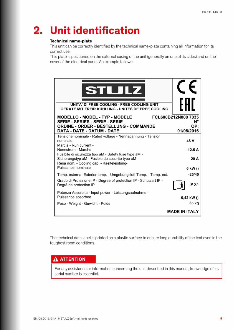
2. Unit identificationTechnical name-plateThis unit can be correctly identified by the technical name-plate containing all information for its correct use.This plate is positioned on the external casing of the unit (generally on one of its sides) and on the cover of the electrical panel. An example follows:
The technical data label is printed on a plastic surface to ensure long durability of the text even in the toughest room conditions.
ATTENTION
For any assistance or information concerning the unit described in this manual, knowledge of its serial number is essential.
10
F R E E-A I R -3
EN/08.2016/34A © STULZ SpA – all rights reserved
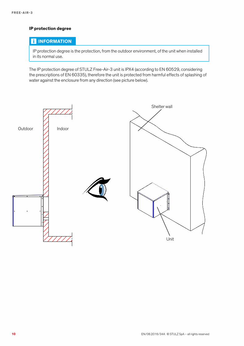
IP protection degree
INFORMATION
IP protection degree is the protection, from the outdoor environment, of the unit when installed in its normal use.
The IP protection degree of STULZ Free-Air-3 unit is IPX4 (according to EN 60529, considering the prescriptions of EN 60335), therefore the unit is protected from harmful effects of splashing of water against the enclosure from any direction (see picture below).
Outdoor Indoor
Unit
Shelter wall
11
F R E E-A I R -3
FCL 60 0 B 2 12 N 000
EN/08.2016/34A © STULZ SpA – all rights reserved
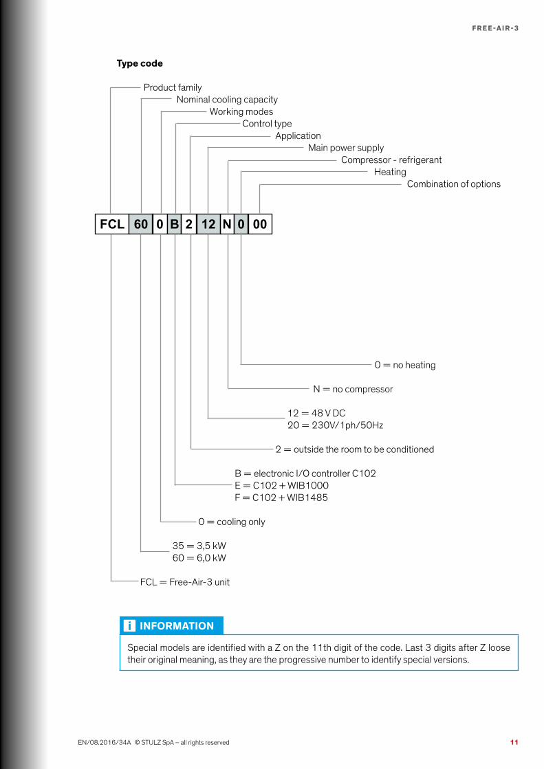
Type code
Product family Nominal cooling capacity Working modes Control type Application Main power supply Compressor - refrigerant Heating Combination of options
0 = no heating N = no compressor 12 = 48 V DC 20 = 230V/1ph/50Hz 2 = outside the room to be conditioned B = electronic I/O controller C102 E = C102 + WIB1000 F = C102 + WIB1485 0 = cooling only
35 = 3,5 kW 60 = 6,0 kW FCL = Free-Air-3 unit
INFORMATION
Special models are identified with a Z on the 11th digit of the code. Last 3 digits after Z loose their original meaning, as they are the progressive number to identify special versions.
12
F R E E-A I R -3
EN/08.2016/34A © STULZ SpA – all rights reserved
3. Components and operating principle
3.1. Intended and non-intended useSTULZ Free-Air-3 units are designed for cooling shelters / rooms suitably protected from weather. Their use allows to eliminate problems caused by high internal temperatures. G4 filtration degree of external air prevents the intrusion of larger dust and dirt particles inside the ambient to be conditioned.STULZ Free-Air-3 units have to be installed externally on the wall of the shelter or cabinet to be conditioned, whose internal side is not accessible to the general public (see DIN EN 60335-2-40, paragraph 3.119).
INFORMATION
To get a cooling effect from Free-Air-3 working, it is absolutely necessary that outside temperature is lower than inside temperature.
Free-Air-3 units must not be installed and used in other positions than the one for which they have been designed. STULZ is not liable for any damage resulting from non-compliant installations. The operator bears the entire risk.
Non-intended useAir conditioner cannot be installed on movable, vibrating, oscillating, tilted (non-levelled) parts.
Generally, air conditioner cannot be installed in the following areas:• With strong heat radiation• With strong magnetic fields• With free flames• With fire risk• With inflammable products• With explosive atmosphere • With saline atmosphere• With aggressive atmosphere
For any doubt, please consult the manufacturer.

13
F R E E-A I R -3
EN/08.2016/34A © STULZ SpA – all rights reserved
With Free-Air-3 units the following site configurations are possible:
1. FCL stand-alone• Free cooling: made by FCL. Working logic: FCL control (C102)• Cooling: not possible
2. FCL + A/C comfort unit not connected to FCL (no limits to the number of A/C units)• Features of A/C units: no specific requests• Free cooling: made by FCL. Working logic: FCL control (C102)• Cooling: made by A/C units. Working logic: A/C unit control• Link FCL => A/C units: no link
3. FCL + A/C comfort unit connected to FCL (max two A/C units connected)• Features of A/C units: automatic restart after interruption of power supply. Power supply single
phase 230V AC, max absorbed current as shown on wiring diagram• Free cooling: made by FCL. Working logic: FCL control (C102)• Cooling: made by A/C units. Working logic: on-off control by FCL (C102)• Link FCL => A/C units: voltage-free signal interrupting A/C power supply line
Main power supply A/C #2 K2 and K3 relays on C102 controller
Main power supply A/C #1
14
F R E E-A I R -3
EN/08.2016/34A © STULZ SpA – all rights reserved
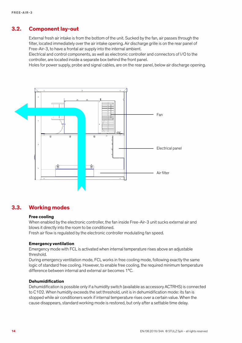
3.2. Component lay-outExternal fresh air intake is from the bottom of the unit. Sucked by the fan, air passes through the filter, located immediately over the air intake opening. Air discharge grille is on the rear panel of Free-Air-3, to have a frontal air supply into the internal ambient.Electrical and control components, as well as electronic controller and connectors of I/O to the controller, are located inside a separate box behind the front panel.Holes for power supply, probe and signal cables, are on the rear panel, below air discharge opening.
3.3. Working modesFree coolingWhen enabled by the electronic controller, the fan inside Free-Air-3 unit sucks external air and blows it directly into the room to be conditioned.Fresh air flow is regulated by the electronic controller modulating fan speed.
Emergency ventilationEmergency mode with FCL is activated when internal temperature rises above an adjustable threshold.During emergency ventilation mode, FCL works in free cooling mode, following exactly the same logic of standard free cooling. However, to enable free cooling, the required minimum temperature difference between internal and external air becomes 1°C.
DehumidificationDehumidification is possible only if a humidity switch (available as accessory ACTRHS) is connected to C102. When humidity exceeds the set threshold, unit is in dehumidification mode: its fan is stopped while air conditioners work if internal temperature rises over a certain value. When the cause disappears, standard working mode is restored, but only after a settable time delay.
Fan
Electrical panel
Air filter

15
F R E E-A I R -3
EN/08.2016/34A © STULZ SpA – all rights reserved
3.4. Mechanical componentsCasingThese machines are composed using self-supporting panels. These are made of passivated and baked enamel sheet metal to guarantee good corrosion resistance (suitable only in non-corrosive and non-salty environments). They make the machine easy to inspect and, at the same time, offer adequate protection to its internal components. Internal components are accessible only by removing frontal panel, extracting its fastening screws with suitable tools.
Air filterAir filter has G4 efficiency class, zig-zag type to increase the surface of air passage and thus reduce the frequency of maintenance operations to clean / replace it. It is designed to prevent large dirt particles present in the environment from entering the internal ambient.
Fixing bracketsConsisting of steel zinc plate sheet with a powder coating as a protection against corrosion (suitable only in non-corrosive and non-salty environments). To fix the unit to the wall, use these brackets, following instructions in chapter "5. Installation".
3.5. MotorsFanThe fan is radial EC type, with metal rotor, on bearings. These fans are manufactured in accordance with Standard EN 60950-1. They are treated with anticorrosion plastic materials, with class I insulation and class I protection. The motor protection is IP54 (AC)/ IP42 (DC), in accordance with Standard DIN40500 whereas the safety rate complies with Standards DIN30110.Noise levels are consistent with Standard DIN 45635.
3.6. Control, monitoring and safety componentsAll equipment is set and inspected at the factory and generally does not require further adjustments or interventions.If, for specific reasons, it becomes necessary to perform modifications on the settings of automatic devices, this task must only be performed, subsequent to notification to the STULZ engineering service, by specialized product expert.STULZ units are equipped with a set of devices designed to ensure proper operation. Intervention by any one of these automatic safety devices is a sign of a malfunction and it is absolutely necessary to eliminate the cause of the malfunction.
DANGER
It is prohibited to make electrical by-passes on safety equipment. This intervention, in addition to being dangerous, also immediately invalidates guarantee coverage for the product.
Interrupt electrical power to the unit before performing any repair or maintenance.
Work on the unit must only be done by expert, qualified and authorized personnel.
Automatic circuit breaker of the fanIt protects against short circuits and excessive motor current. They have adjustable thermal and magnetic triggering devices.
16
F R E E-A I R -3
EN/08.2016/34A © STULZ SpA – all rights reserved
Temperature probes2 PTC temperature probes are connected to analogue inputs of C102 controller, in order to measure following parameters:• Internal air temperature: shipped loose with screened cable 8 m long• External air temperature mounted inside the unit.
STANDARD COMPONENTS WITH FREE-AIR-3
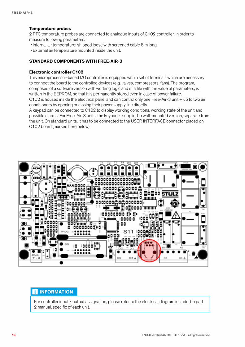
Electronic controller C102This microprocessor-based I/O controller is equipped with a set of terminals which are necessary to connect the board to the controlled devices (e.g. valves, compressors, fans). The program, composed of a software version with working logic and of a file with the value of parameters, is written in the EEPROM, so that it is permanently stored even in case of power failure.C102 is housed inside the electrical panel and can control only one Free-Air-3 unit + up to two air conditioners by opening or closing their power supply line directly.A keypad can be connected to C102 to display working conditions, working state of the unit and possible alarms. For Free-Air-3 units, the keypad is supplied in wall-mounted version, separate from the unit. On standard units, it has to be connected to the USER INTERFACE connector placed on C102 board (marked here below).
INFORMATION
For controller input / output assignation, please refer to the electrical diagram included in part 2 manual, specific of each unit.
17
F R E E-A I R -3
EN/08.2016/34A © STULZ SpA – all rights reserved
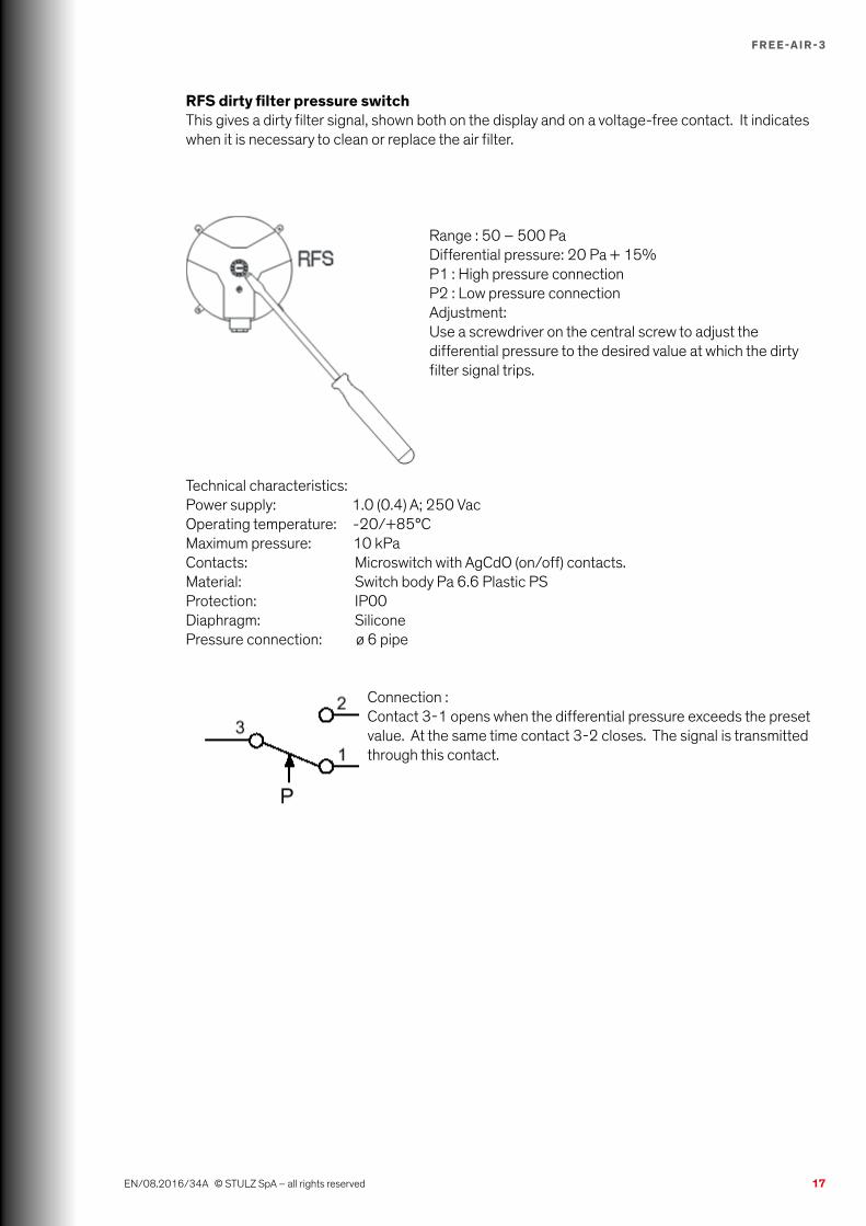
RFS dirty filter pressure switchThis gives a dirty filter signal, shown both on the display and on a voltage-free contact. It indicates when it is necessary to clean or replace the air filter.
Range : 50 – 500 PaDifferential pressure: 20 Pa + 15%P1 : High pressure connectionP2 : Low pressure connectionAdjustment:Use a screwdriver on the central screw to adjust the differential pressure to the desired value at which the dirty filter signal trips.
Technical characteristics:Power supply: 1.0 (0.4) A; 250 VacOperating temperature: -20/+85°CMaximum pressure: 10 kPaContacts: Microswitch with AgCdO (on/off) contacts.Material: Switch body Pa 6.6 Plastic PSProtection: IP00Diaphragm: SiliconePressure connection: ø 6 pipe
Connection :Contact 3-1 opens when the differential pressure exceeds the preset value. At the same time contact 3-2 closes. The signal is transmitted through this contact.
18
F R E E-A I R -3
EN/08.2016/34A © STULZ SpA – all rights reserved
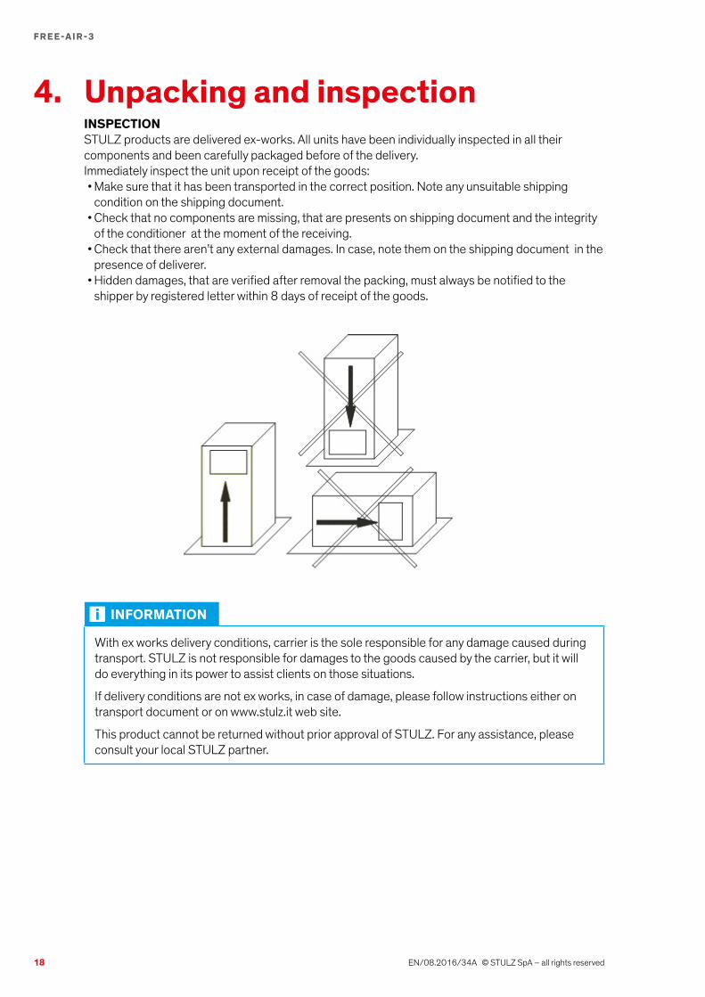
4. Unpacking and inspectionINSPECTIONSTULZ products are delivered ex-works. All units have been individually inspected in all their components and been carefully packaged before of the delivery.Immediately inspect the unit upon receipt of the goods:• Make sure that it has been transported in the correct position. Note any unsuitable shipping
condition on the shipping document.• Check that no components are missing, that are presents on shipping document and the integrity
of the conditioner at the moment of the receiving.• Check that there aren’t any external damages. In case, note them on the shipping document in the
presence of deliverer.• Hidden damages, that are verified after removal the packing, must always be notified to the
shipper by registered letter within 8 days of receipt of the goods.
INFORMATION
With ex works delivery conditions, carrier is the sole responsible for any damage caused during transport. STULZ is not responsible for damages to the goods caused by the carrier, but it will do everything in its power to assist clients on those situations.
If delivery conditions are not ex works, in case of damage, please follow instructions either on transport document or on www.stulz.it web site.
This product cannot be returned without prior approval of STULZ. For any assistance, please consult your local STULZ partner.

19
F R E E-A I R -3
EN/08.2016/34A © STULZ SpA – all rights reserved
LIFTING AND TRANSPORTThis unit doesn’t need particular precautions for transport.When more units are packed together on a pallet, use a fork lift, taking care that the centre of gravity is inside fork area.
DANGER
Capacity of lifting device must be appropriate for the weight of air conditioner.
Load must be balanced to avoid tilting.
Avoid offhanded or rough manoeuvres.
Don’t lay other objects upon the air conditioner.
STORAGEExcept differently agreed, standard packing of air conditioners is composed of carton box and corner protections.
INFORMATION
Standard packing doesn’t protect air conditioner from rain and bad weather.
Standard packing is not suitable for seafreight.
Standard packing is not suitable for airfreight
Following information can be found on packing:• STULZ logo• Unit code• Accessories put in the packing• Warning symbols
If unit is stored before installation, comply with following instructions:• Don’t expose to direct solar radiation• Store the unit with its original packing
Ambient conditions for storage are the following:• Ambient temperature min / max = -20°C / +60°C• Max humidity RH 90%
REMOVAL OF PACKING• Remove packing without damaging air conditioner: remove top air bag, external film, lateral and
corner protections• Recover any document or component inside the packing• Keep original packing (pallet and protections) for future shipments
ATTENTION
Use original packing to ship the air conditioner to any other destination.
If packing disposal is necessary, we remind to dispose different materials suitably (see chapter "10. Uninstalling and disposal of the unit").
20
F R E E-A I R -3
EN/08.2016/34A © STULZ SpA – all rights reserved
5. Installation DANGER
Never work on the unit without disconnecting all power supplies before. Prior to drilling holes or making cuts on the cabinet, make sure that holes, screws, cables, etc. do not interfere with the equipment which has already been installed.
5.1. Positioning and mechanical installation1. Free-air-3 units must be installed outside the room to be conditioned.2. Check that:
• There is space enough for an easy application, installation and maintenance, both inside and outside the ambient to be conditioned. In any case, minimum distances indicated in the drawings on following pages must be respected;
• The wall or door where the unit has to be fixed can support its weight;• The room to be conditioned is clean on the inside;• The unit is not in the proximity of heat sources or warm air flows;• The structure is water tight;• The inside of the room allows a proper air circulation, preventing any recirculation;• If it is installed on a door, make sure that the hinges are strong enough to support the unit. Make
sure that the electric cable does not get torn or damaged when the door is closed. If the depth of the Free-Air-3 prevents the door from being completely opened, arrange a stopper for such a door.
3. The Free-Air-3 unit must be installed as low as possible to improve “displacement effect”. However, please consider minimum distance from ground for servicing and ensuring a good cleanliness of freash air intaken.
4. Two openings are required on the walls• One is for fresh air intake. This opening must be made according to the relevant cut-out in the
following pages.• The other opening is for exhaust air discharge. It should be placed in a position which allows
a good air circulation during free cooling, avoiding short circuits of air and allowing fresh air to reach the relevant points to be cooled. Suggested positions are shown in the two following drawings. An overpressure damper must be installed on this opening, to avoid internal air going out from it during operation of air conditioners. This damper is available with accessory code ACTODALFCL. The opening on the wall must be made according to the cut-out in paragraph 8.2. If a different overpressure damper is installed, the area of this opening must be at least 0.10 m2
21
F R E E-A I R -3
EN/08.2016/34A © STULZ SpA – all rights reserved
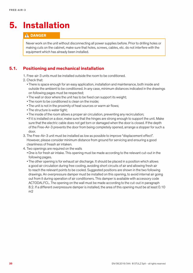
Maintenance from front:A = 1000 mm B = 300 mm
Preferable position when the room is not too long, otherwise air might not reach the farthest points of the room.
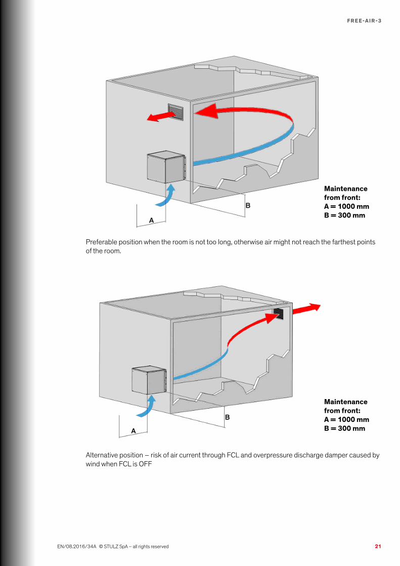
Maintenance from front:A = 1000 mm B = 300 mm
Alternative position – risk of air current through FCL and overpressure discharge damper caused by wind when FCL is OFF
22
F R E E-A I R -3
EN/08.2016/34A © STULZ SpA – all rights reserved
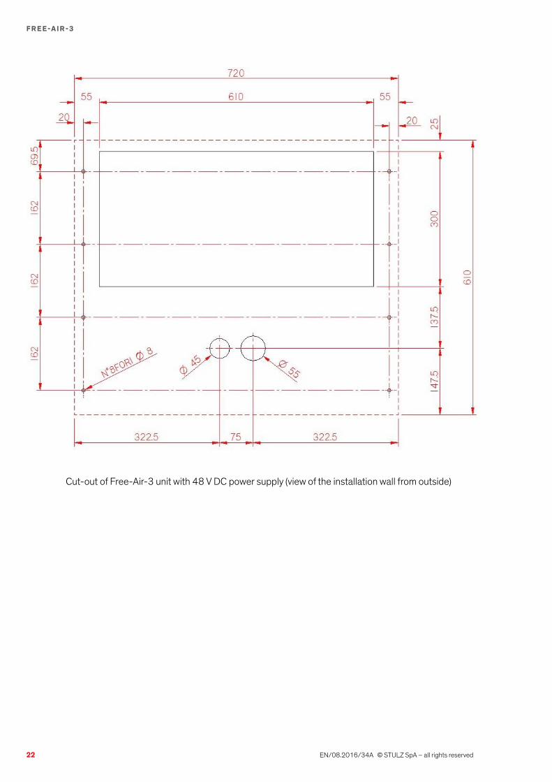
Cut-out of Free-Air-3 unit with 48 V DC power supply (view of the installation wall from outside)
23
F R E E-A I R -3
EN/08.2016/34A © STULZ SpA – all rights reserved
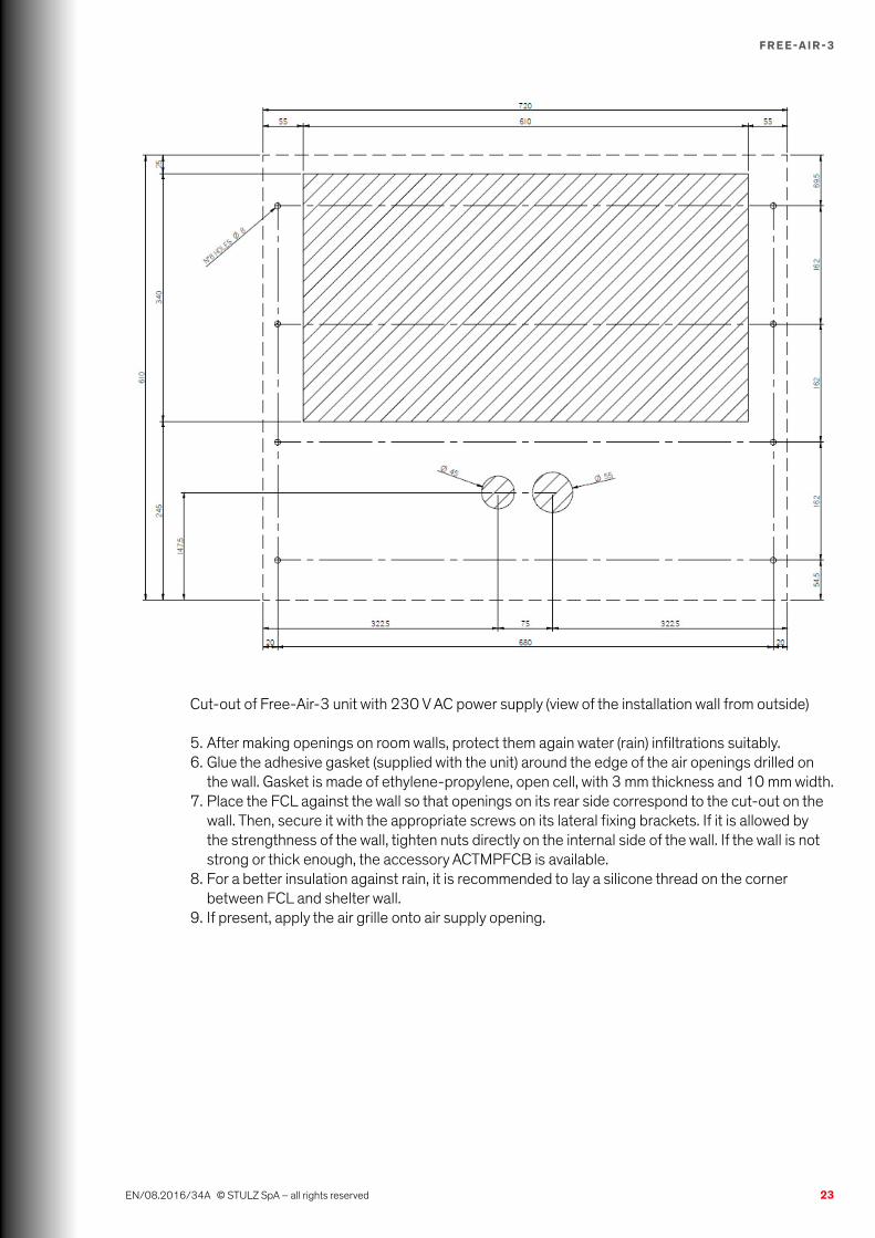
Cut-out of Free-Air-3 unit with 230 V AC power supply (view of the installation wall from outside)
5. After making openings on room walls, protect them again water (rain) infiltrations suitably.6. Glue the adhesive gasket (supplied with the unit) around the edge of the air openings drilled on
the wall. Gasket is made of ethylene-propylene, open cell, with 3 mm thickness and 10 mm width.7. Place the FCL against the wall so that openings on its rear side correspond to the cut-out on the
wall. Then, secure it with the appropriate screws on its lateral fixing brackets. If it is allowed by the strengthness of the wall, tighten nuts directly on the internal side of the wall. If the wall is not strong or thick enough, the accessory ACTMPFCB is available.
8. For a better insulation against rain, it is recommended to lay a silicone thread on the corner between FCL and shelter wall.
9. If present, apply the air grille onto air supply opening.

24
F R E E-A I R -3
EN/08.2016/34A © STULZ SpA – all rights reserved
ATTENTION
Do not block off circulation of air intaken and/or expelled by the Free-Air-3
Accessory ACTMPFCB
8 x M6 nuts + lock washers
8 x M6 screws + lock washers

25
F R E E-A I R -3
EN/08.2016/34A © STULZ SpA – all rights reserved
5.2. Electrical connections
DANGER
It is absolutely necessary, before making any connections, to use a suitable tester to check the voltage supply. This must be the same as the voltage indicated on the technical data plate.
The user must furnish and install, upstream from the unit, an omni-pole automatic switch with capacity as specified on the technical data plate in order to be able to perform maintenance on the unit in the absence of electricity.
The ON/OFF key on the C102 keypad (if present) is only used for the unit stand-by. Therefore, it must not be considered as a safety element to perform maintenance on the unit. Maintenance must be done after disconnecting the power supply of the unit (see note above).
Any signal cable (temperature probes, alarms, keypad) longer than 3 m must be screened against electromagnetic disturbs.
Electrical connections have to be carried out only by authorized technical personnel.
Electrical wiring of this unit must be executed in compliance with following norms:• Machinery Directive (2006/42/EEC – 98/37/EEC)• Low voltage (2006/95/EEC)• Electromagnetic compatibility (2004/108/EEC)• National rules for technical plants
1. Check the supply voltage and verify if it is within the admitted range of the unit. Check also power supply of air conditioners, if present.
2. Interrupt power supply before working on the system: make sure that the main switch is turned off and the system is isolated from power mains; make sure also that all power switches and control fuses in the electric system have been turned off
3. On power supply lines to the FCL, install an omni-pole automatic switch, curve type C (check size on technical data plate of the unit)
4. Check that power cables are installed with a sufficient distance from alarm and signal cables5. Check that the connection cables have a section suitable to the absorbed power and cable
length (refer to Standard EN60204-1, check size on wiring diagram of the unit)6. Run power supply cables through the apposite holes on the rear panel - left side - of the unit and
connect them to the corresponding terminals inside the electrical box of FCL7. Fix the keypad (if supplied) to the wall and wire it to USER connector placed on the connection
board inside the e-box8. If needed, connect signal cables for alarms, inputs to the controller, etc. Signal cables are not
supplied with the unit. They have to be inserted into the corresponding screw terminals inside the e-box of the unit, following wiring diagram.
DANGER
The inobservance of these instructions might provoke damages or malfunction of components and the warranty shall become forthwith void.
26
F R E E-A I R -3
EN/08.2016/34A © STULZ SpA – all rights reserved
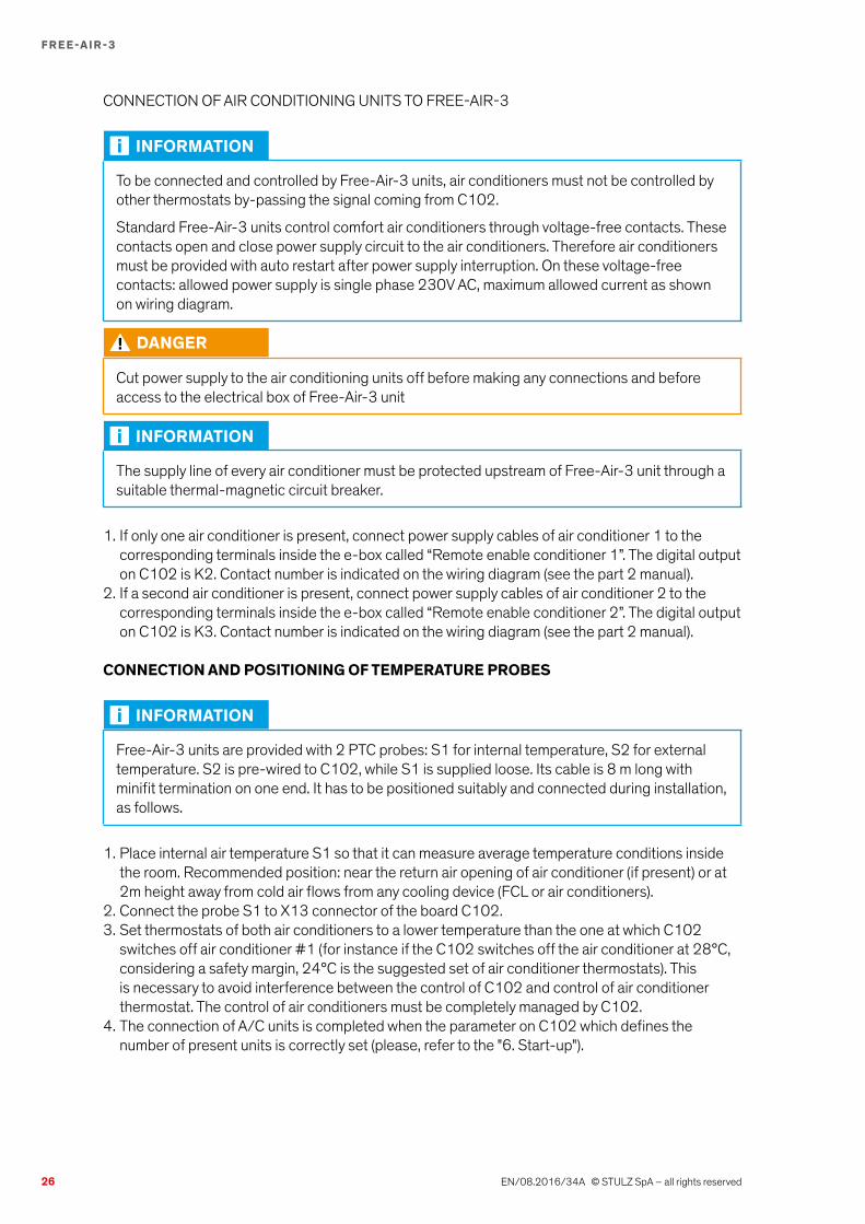
CONNECTION OF AIR CONDITIONING UNITS TO FREE-AIR-3
INFORMATION
To be connected and controlled by Free-Air-3 units, air conditioners must not be controlled by other thermostats by-passing the signal coming from C102.
Standard Free-Air-3 units control comfort air conditioners through voltage-free contacts. These contacts open and close power supply circuit to the air conditioners. Therefore air conditioners must be provided with auto restart after power supply interruption. On these voltage-free contacts: allowed power supply is single phase 230V AC, maximum allowed current as shown on wiring diagram.
DANGER
Cut power supply to the air conditioning units off before making any connections and before access to the electrical box of Free-Air-3 unit
INFORMATION
The supply line of every air conditioner must be protected upstream of Free-Air-3 unit through a suitable thermal-magnetic circuit breaker.
1. If only one air conditioner is present, connect power supply cables of air conditioner 1 to the corresponding terminals inside the e-box called “Remote enable conditioner 1”. The digital output on C102 is K2. Contact number is indicated on the wiring diagram (see the part 2 manual).
2. If a second air conditioner is present, connect power supply cables of air conditioner 2 to the corresponding terminals inside the e-box called “Remote enable conditioner 2”. The digital output on C102 is K3. Contact number is indicated on the wiring diagram (see the part 2 manual).
CONNECTION AND POSITIONING OF TEMPERATURE PROBES
INFORMATION
Free-Air-3 units are provided with 2 PTC probes: S1 for internal temperature, S2 for external temperature. S2 is pre-wired to C102, while S1 is supplied loose. Its cable is 8 m long with minifit termination on one end. It has to be positioned suitably and connected during installation, as follows.
1. Place internal air temperature S1 so that it can measure average temperature conditions inside the room. Recommended position: near the return air opening of air conditioner (if present) or at 2m height away from cold air flows from any cooling device (FCL or air conditioners).
2. Connect the probe S1 to X13 connector of the board C102.3. Set thermostats of both air conditioners to a lower temperature than the one at which C102
switches off air conditioner #1 (for instance if the C102 switches off the air conditioner at 28°C, considering a safety margin, 24°C is the suggested set of air conditioner thermostats). This is necessary to avoid interference between the control of C102 and control of air conditioner thermostat. The control of air conditioners must be completely managed by C102.
4. The connection of A/C units is completed when the parameter on C102 which defines the number of present units is correctly set (please, refer to the "6. Start-up").
27
F R E E-A I R -3
EN/08.2016/34A © STULZ SpA – all rights reserved
6. Start-up INFORMATION
Before you first start up the system install and connect it up as described in the “Installation” chapter.
Two keypads are available for C102: ACTKPDC1010 is a 4x20 display and is necessary for the start-up of the units. Only this keypad allows full access to all parameters. ACTUKPD is a keypad with 3-digit display for user functions, such as set points setting, alarm display and reset, counters display.
In this chapter TI = internal temperature; TAE = external air temperature.
• Make sure the main switch is turned off and that the system is isolated from power mains.• Check that all power switches and control fuses in the electric system have been turned off.• Double check that the main electrical supply cable and the terminals, including the PE terminals,
are correctly hooked up.• Check that contactors are free to move.• Double check if signal cables are correctly connected and fastened to the electrical terminals of
the unit (according to wiring diagram).• Double check correct positioning and fastening of temperature probe S1.
6.1. Controller setting• Close all unit panels.• Use the main switch to turn the FCL on.• Activate automatic switch on 48V DC power supply line.• Check software version loaded on C102 controller on one of the main screens of display.
6.2. Functional checks• At this point the electronic board is powered and individual components can be enabled to check
they work properly. Software of C102 includes a semi-automatic test procedure to be used during the start-up. This procedure, as well as access to the other main menus, is described in the next paragraph. For a detailed description of every function of C102 electronic controller, please consult its specific manual.
INFORMATION
Test procedure can be accessed only with keypad ACTKPDC1010. 3-digit keypad ACTUKPD is not useful to this purpose.
28
F R E E-A I R -3
EN/08.2016/34A © STULZ SpA – all rights reserved
In addition to the semi-automatic test, some other electrical measurements are necessary to exclude any fault on the FCL.• Start the FCL by pressing the ON-OFF push-button on the display.• Enter MANUAL CONTROL and arrive to “Time going out from manual control”. Set this time at
least to 5 minutes.• Then, remaining inside MANUAL CONTROL, arrive to “Fan 1”. Set speed to 35%.• Check power supply voltage: nominal value 48V DC (admitted range 36÷56 V DC).• Check current absorbed by the fan (FCL35 = 0,7 A / FCL60 = 2,4 A at 48 V DC).• Restore “Fan 1” to 0 and exit MANUAL CONTROL. In any case, C102 will go out from manual
control within the value set for “Time going out from manual control”.• Check that no alarms appear in standard working conditions.
6.3. Other tests (facultative)
INFORMATION
To change temperature measured by the probes, heat or cool their bulbs physically or alterate their offset. To enable FCL working, free cooling conditions must be respected: TI – TAE > 2°C in normal conditions and 1°C in emergency mode.
• Change temperature measured by internal probe (S1) and, if needed, temperature measured by external probe (S2) to have free cooling conditions. Verify at different internal temperatures if working logic is according to working diagrams on this manual.
• Check emergency mode and high temperature alarm, increasing temperature measured by internal temperature probe above E0401 (threshold of emergency mode) and B03 (threshold of high temperature alarm - please consider the delay of 10 s for this alarm).
ATTENTION
After that, restore all offsets to 0.
6.4. ShutdownTo shut the unit down disconnect it from all its power supplies using the related isolating switches. Disconnect also any A/C unit connected to the Free-Air-3 unit, using its isolating switch.
DANGER
The ON-OFF key on the C102 display (if present) is only used to put the unit in stand-by. It must not be thought to be a safety component to turn the unit off prior to performing maintenance.
29
F R E E-A I R -3
EN/08.2016/34A © STULZ SpA – all rights reserved
7. Maintenance7.1. Safety instructions
Start-up and maintenance of Free-Air-3 units might be dangerous if they are not carried out with the same precautions used for apparels with moving parts and electric components. Installation and intervention on air conditioners must be made in full compliance with specific national regulations for accident prevention, with particular reference on electric equipment. Failure to comply with these regulations might be dangerous to people and environment.Before any intervention on the unit, refer to instructions on this manual, check data on the name-plate and take any other precaution in order to guarantee optimal safety.Maintenance interventions must be performed by authorized and qualified technicians.
Safety procedures
DANGER
Cut off the power supply to the unit before making any maintenance operation. A “DO NOT SWITCH ON” warning sign must be clearly visible. ON-OFF key on display (if present) is only used to put the unit is stand-by. It must not be considered as a safety device to switch off the unit before maintenance.
Some verifications must be effected with the unit in operation (measuring current, pressures, temperatures). In such a case, the unit must only be switched on at the master switch after all mechanical connections have been carried out. The unit must be switched off immediately after the measuring procedure.
Moving parts are totally automatic and highly reliable and ordinary maintenance is reduced to a minimum. This maintenance, however, must be performed at the prescribed intervals.Failure to perform maintenance compromises FCL operation and durability and invalidates warranty coverage.
7.2. Preventative maintenance scheduleEvery three months• FAN: check that fan motors and other components do not show abnormal vibrations or show signs
of overheating.• AIR FILTERS: check that air openings are clean and that dirt does not prevent the passage of air.
Check air pre-filter (if present) and clean it if necessary. Check air filter and clean or replace it if necessary. If filter needs to be replaced, use a spare filter with the same dimensions and efficiency of the original one. Spare filters can be ordered to STULZ Service Department.
Every year• ELECTRIC CIRCUIT: check that electric connections are tight, that switches, remote control
switches and isolating switches are operating and in good condition. Also check that the control board operates and perform a test of alarm signals.
• MECHANICAL PARTS: clean the inner components of the system.

30
F R E E-A I R -3
EN/08.2016/34A © STULZ SpA – all rights reserved
ATTENTION
More frequent cleanings must be done if the unit works in particularly dirty environments or if experience requires them.
7.3. Cleaning / replacement of componentsWe recommend replacing fans every 40000 operating hours (MTBF calculated at 40°C working temperature).To replace fan, unscrew and open frontal panel, then unscrew fan support and remove it.To remove both the pre-filter (if present) and the filter, unscrew and open the frontal, as shown on the following drawings. To clean the pre-filter, use water. To clean the filter use compressed air, blowing it in the direction opposite the flow of air that normally passes through it (blow with compressed air at pressures not exceeding 0,2 bar).
7.4. General appliance cleaning proceduresThe metal casing of the unit can be cleaned using a detergent liquid as long as this liquid is compatible with: PVC, polyethylene, silicone and polyester coating. Be careful not to wet the electrical connections inside the unit.
ATTENTION
Use of an unsuitable detergent could cause damage to the unit. Do not use acid or caustic substances to clean any part of the unit.
Use a vacuum cleaner to remove dust.Inner parts must be cleaned with a liquid detergent and air at a pressure not higher than 4 bar and with the unit suitably connected to ground.
31
F R E E-A I R -3
EN/08.2016/34A © STULZ SpA – all rights reserved
8. Options8.1. Aluminium casing – PAKAL
With this option, external panels and fixing flanges of FCL units are made of aluminium alloy sheet. As standard, with aluminium casing, units are not painted.
8.2. Stainless steel casing – PAKINWith this option, external panels and fixing flanges of FCL units are made of stainless steel AISI 304 sheet. As standard, with stainless steel casing, units are painted like the units with zinc plated sheet casing.
8.3. WIB1000 / WIB1485The WIB1000 / WIB1485 is a single-point Ethernet interface and it’s used for the SNMP supervision, web monitoring and OnBoard communication. It’s also possible to update the firmware and the parameters list through an USB key, formatted as FAT32.When present, WIB1000 / WIB1485 is soldered directly on the SPI connector of the mother board. WIB1000 is the option without the serial interface 485, while WIB1485 is the option with serial interface 485.
9. Information on residual hazards and emergency situationsThis unit has been designed so as to minimize any danger situations. Such situations arise mainly from an improper use of the product and the failure to comply with installation, use and maintenance standards.This information must be made known to all personnel operating this unit and in the proximity thereof.
9.1. General safety provisionsAll personnel responsible for testing, operating and servicing this unit, must be familiar with the following safety provisions:• Hazards tags and notices must be readily visible in any potential hazard areas.• A monitoring service must be arranged in such hazard areas.• Supervisors must keep in constant touch with monitors.• Transit areas, doorways and stairways, in the proximity of the unit must be kept clear.• Emergency exits must be kept clear at all times.• Slippery areas, which are a hazard to personnel, must be covered with anti-slip material.• For any specific activity, specific tools and procedures must be used.• Testing tools and equipment must be kept in good working order.

32
F R E E-A I R -3
EN/08.2016/34A © STULZ SpA – all rights reserved
• Personnel must have a thorough knowledge of methods and procedures used in the event of a fire (make fire extinguishers readily accessible).
• The following steps must be taken at the outbreak of a fire: – Turn off the electric power supply from the part affected by fire – Increase ventilation capacity to evacuate combustion gases – Inform appropriate department.
9.2. Hazards arising from the product coming into contact with things or persons• Danger point 1a) is fan movement. The fan's protective grille prevents passage of bodies with a
diameter higher than 10 mm.
9.3. Hazards arising from electrical faultsSAFETY STANDARDS FOR ELECTRICAL EQUIPMENT IntroductionCauses of electrical hazards are well known and their prevention is not difficult provided constant care is applied.In order to reduce such risks, operators must be informed of potential hazards and trained on the use of safety procedures.
TASKS ASSIGNED TO OFFICERS-IN-CHARGEOfficers-in-charge must be informed of any potential hazards existing in the system and must monitor electric equipment operators. This monitoring function involves identifying possible danger situations and investigating problems encountered by personnel during maintenance procedures. Each faulty part must be repaired or replaced immediately.An officer-in-charge must insist on the use of safety procedures without tolerating or accepting any shortcuts, as this can cause harm to persons and equipment.
HIGH VOLTAGEContact with high voltage circuits can cause burns, shock, loss of consciousness and even the victim's electrocution.This may happen due to lack of awareness of the dangers connected with the use of electrical equipment. The injury suffered by the human body depends on the amount of power as well as on the duration and path followed by the current inside the body.
SAFETY STANDARDS TO COMPLY WITH WHEN THE EQUIPMENT IS TURNED OFF• Before servicing the equipment, disconnect all circuits.• Make sure that no voltage whatsoever is present in the circuit.• Clean and dry the whole area.• Remove pins, rings, brackets or any accessories which may hinder operations or turn into a
potential electrical conductor.• Discharge to earth or short circuit the capacitor terminals connected with the deactivated circuit.• Remove the safety devices only after the circuit has been deactivated.

33
F R E E-A I R -3
EN/08.2016/34A © STULZ SpA – all rights reserved
SAFETY STANDARDS TO COMPLY WITH WHEN SERVICING LIVE EQUIPMENT• Add the following provisions to those under items 2, 3 and 4 above:• Personnel must never operate alone;• If possible, use only one hand to perform work required;• Check wires and instruments regularly;• Use only approved procedures to bypass the interlocks;• Ensure that operators are perfectly familiar with the equipment parts and maintenance
procedures, before servicing the unit;• Use a pair of safety gloves;• Open all contacts which feed power to the equipment before measuring resistance levels;• Check that there is no high voltage in the low voltage circuits;• Do not use magnetic tools RDXC in the proximity of strong magnetic fields.
SAFETY STANDARDS TO COMPLY WITH WHEN SERVICING THE UNIT• If continuous duty is not required, the system must be turned off.• Before commencing work, the following is required:• Check that the maintenance technician is not carrying any objects which may act as conductors;• Inspect the work area to make sure the floor is clean and dry;• Check work tools. They must be suitable for their designated task and in good working order so as
to ensure safe maintenance operations• Check that all gauges are regularly calibrated• Check servicing procedures before commencing work by inspecting the wiring diagram and
visualising the system structure.
When carrying out electrical maintenance operations, the following is required:• The maintenance technician must be familiar with high voltage circuits;• No resistance measurements are to be carried out on live circuits;• Use only one hand to take measurements on live circuits;• Earth all instrument terminals before taking measurements on live circuits.
The above recommendations must be strictly adhered to.Maintenance operations shall be deemed to have been completed only when all parts have been re-installed and the product has regained its original appearance.
9.4. Fire hazardsNo direct danger.
9.5. Toxic substancesNone.

34
F R E E-A I R -3
EN/08.2016/34A © STULZ SpA – all rights reserved
10. Uninstalling and disposal of the unitDismantling of this unit must always be done by expert and authorized personnel.
DANGER
Before starting to dismantle the unit check that it has been disconnected from electric power supply and secure it against being switched on again.
Move the unit as described in paragraph “lifting and transport”, with a lifting device of suitable capacity. The unit must be stored where it is protected from weather while it is awaiting disposal.
Below the instructions for proper disposal of the unit during the various phases of its life. For further clarification or additional information, please contact [email protected].
INFORMATION
To ensure proper and safe disposal activities, operator must equip themselves with the necessary PPE including: anti-cut gloves, oil resistant gloves, heat resistant gloves, safety footwear, safety eyewear against liquid and gas splashes.The context in which the unit is located may require the use of additional PPE, thus it is mandatory to inquire with the relevant staff of the area before starting operation.
Once the materials have been separated as shown below, they should be assigned EWC codes and then sent for disposal in accordance with the national legislation.Disposal related to the unit purchased occurs in three stages:
1. Disposal of packagingThe packaging of the unit must be disposed of ensuring separation of the following materials:• Paper and Cardboard• Wood Packing–Packing materials are not chemically treated unless they are declared to be
“fumigate”• Plastic pallets- high- density polyethylene HDPE• Plastic Film– polyethylene PE• Polystyrene –expanded polystyrene EPS 6
2. Disposal of substances during maintenance operations• The air filters should be disposed of depending on the substances they contain from the
environment in which the units operate
3. Disposal at the end of life of the unitThe unit must be disposed of ensuring separation of the following materials:• Metals• Insulation and sound-absorbing materials• Electric and electronic components• Cables and wiring• Plastic Parts - Plastic parts that are important in terms of weight are the following:

35
F R E E-A I R -3
EN/08.2016/34A © STULZ SpA – all rights reserved
Identified Substance CAS Number
acrylonitrile butadiene styrene terpolymer 9003-56-9
polystyrene homopolymer 9003-53-6
polycarbonatefrom bisphenol A 103598-77-2
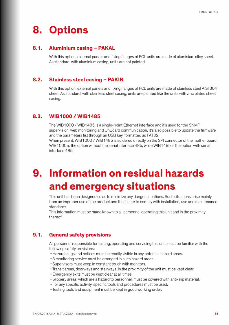
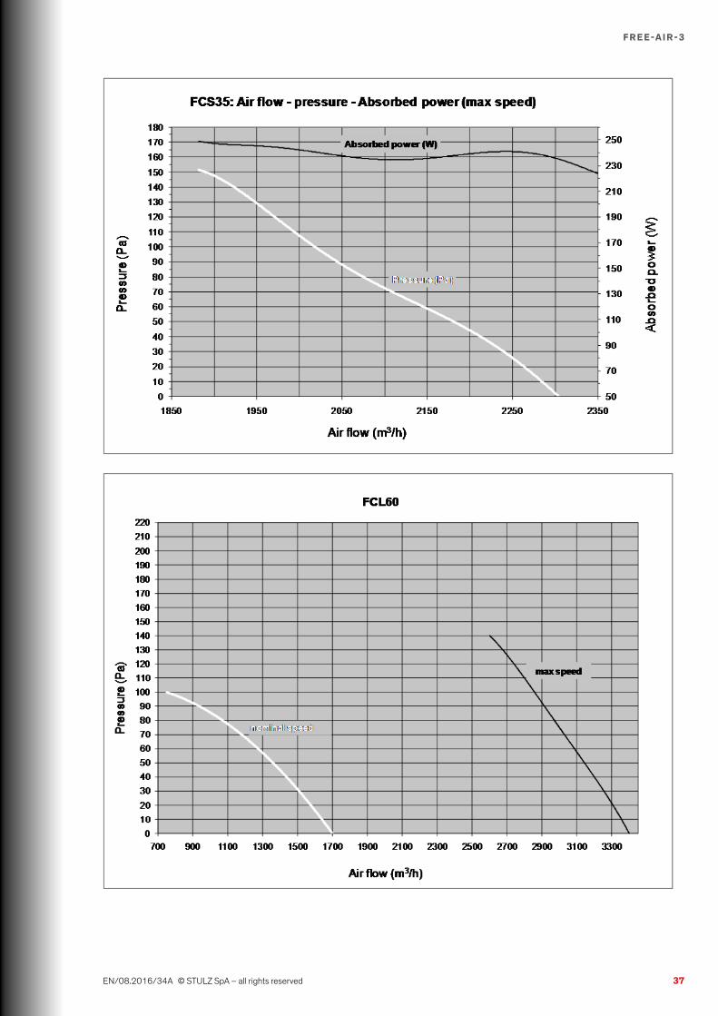
11. Appendix: technical dataNOTES ON TECHNICAL DATA SHEETS* Declared at the following conditions: outside temperature 20°C / inside temperature 30°C / at
nominal voltage. Fan works at maximum speed. Gross cooling capacities (power dissipated by treatment fan is not deducted).
** Max fan speed.*** Measured at 1 m distance from the unit, free field, working in nominal conditions.
MODEL FCL350B212N000 FCL600B212N000 FCL350B220N000 FCL600B220N000
Nominal cooling capacity (DT°=10°C)*
kW3,5 6,0 3,5 6,0
EER index* W/W 97,2 51,7 70 46,2
Outside operating limit temp. min/max
°C-25 / +60 -25 / +40 -25 / +45 -25 / +40
Inside operating limit temp. min/max
°C/ / / /
External sound pressure level***
db(A)44 46 44 46
Weight kg 35 35 35 35
Height / Width / Depth mm 612 / 720 / 604 612 / 720 / 604 612 / 720 / 604 612 / 720 / 604
Inlet Fan
Number / Type 1 / EC radial 1 / EC radial 1 / EC radial 1 / EC radial
Nominal air flow* m3/h 1050 1724 1050 1724
Max speed air flow** m3/h 2300 3400 2300 3400
Electric data
Nominal voltage V 48 DC 48 DC 230V/1ph/50Hz 230V/1ph/50Hz
Voltage range V 36 ÷ 56 DC 36 ÷ 56 DC 200 ÷ 277 AC 200 ÷ 277 AC
Voltage tolerance / / ± 10 % ± 10 %
Nominal frequency Hz / / 50 - 60 50 - 60
Frequency tolerace / / ± 2 % ± 2 %
Power consumption: nominal conditions*
kW0,036 0,116 0,05 0,13
Power consumption: max speed**
kW0,236 0,420 0,45 0,5
Nominal operating current (NOA)*
A0,7 2,4 0,39 1,0
Max operating current (MOA) A 5,2 12,5 2,9 3,15

36
F R E E-A I R -3
EN/08.2016/34A © STULZ SpA – all rights reserved
37
F R E E-A I R -3
EN/08.2016/34A © STULZ SpA – all rights reserved

38
F R E E-A I R -3
EN/07.2016/34A © STULZ SpA – all rights reserved

STULZ S.P.A. ITALY Valeggio sul Mincio (VR) Tel. +39 045 / 6331615 [email protected]
HEADQUARTERS HAMBURG GERMAN Tel. +49 040 / 5585-238 [email protected]
OTHER AREAS on
www.stulz.com
For general questions about our products and services, you can reach us on weekdays from 8.30 – 17.30 at phone 0039 045 6331615.
For sales and support inquiries, please make a selection below to find your local contact.
STULZ Top Service – more than quick emergency assistance
Service-PortalClimate CustomizedMaintenance Test CenterAdvice Technical Implementation