+front p5ld2-vm dhdlsvr04.asus.com/pub/asus/mb/socket775/p5ld2-vm dh... · iii contents...
TRANSCRIPT

Mot
herb
oard
P5LD2-VM DH

i ii ii ii ii i
Copyright © 2006 ASUSTeK COMPUTER INC. All Rights Reserved.No part of this manual, including the products and software described in it, may be reproduced,transmitted, transcribed, stored in a retrieval system, or translated into any language in any formor by any means, except documentation kept by the purchaser for backup purposes, without theexpress written permission of ASUSTeK COMPUTER INC. (“ASUS”).Product warranty or service will not be extended if: (1) the product is repaired, modified oraltered, unless such repair, modification of alteration is authorized in writing by ASUS; or (2)the serial number of the product is defaced or missing.
ASUS PROVIDES THIS MANUAL “AS IS” WITHOUT WARRANTY OF ANY KIND, EITHEREXPRESS OR IMPLIED, INCLUDING BUT NOT LIMITED TO THE IMPLIED WARRANTIESOR CONDITIONS OF MERCHANTABILITY OR FITNESS FOR A PARTICULAR PURPOSE.IN NO EVENT SHALL ASUS, ITS DIRECTORS, OFFICERS, EMPLOYEES OR AGENTS BELIABLE FOR ANY INDIRECT, SPECIAL, INCIDENTAL, OR CONSEQUENTIAL DAMAGES(INCLUDING DAMAGES FOR LOSS OF PROFITS, LOSS OF BUSINESS, LOSS OF USEOR DATA, INTERRUPTION OF BUSINESS AND THE LIKE), EVEN IF ASUS HAS BEENADVISED OF THE POSSIBILITY OF SUCH DAMAGES ARISING FROM ANY DEFECT ORERROR IN THIS MANUAL OR PRODUCT.
SPECIFICATIONS AND INFORMATION CONTAINED IN THIS MANUAL ARE FURNISHEDFOR INFORMATIONAL USE ONLY, AND ARE SUBJECT TO CHANGE AT ANY TIMEWITHOUT NOTICE, AND SHOULD NOT BE CONSTRUED AS A COMMITMENT BY ASUS.ASUS ASSUMES NO RESPONSIBILITY OR LIABILITY FOR ANY ERRORS ORINACCURACIES THAT MAY APPEAR IN THIS MANUAL, INCLUDING THE PRODUCTSAND SOFTWARE DESCRIBED IN IT.
Products and corporate names appearing in this manual may or may not be registeredtrademarks or copyrights of their respective companies, and are used only for identification orexplanation and to the owners’ benefit, without intent to infringe.
E2978E2978E2978E2978E2978
Second Edit ion V2Second Edit ion V2Second Edit ion V2Second Edit ion V2Second Edit ion V2December 2006December 2006December 2006December 2006December 2006

i i ii i ii i ii i ii i i
Contents
Notices ................................................................................................ viSafety information ............................................................................. viiAbout this guide ............................................................................... viiiTypography ......................................................................................... ixP5LD2-VM specifications summary ..................................................... x
Chapter 1: Product introductionChapter 1: Product introductionChapter 1: Product introductionChapter 1: Product introductionChapter 1: Product introduction1.1 Welcome! .............................................................................. 1-21.2 Package contents ................................................................. 1-21.3 Special features .................................................................... 1-2
1.3.1 Product highlights ................................................... 1-21.3.2 Innovative ASUS features ....................................... 1-5
1.4 Before you proceed .............................................................. 1-61.5 Motherboard overview .......................................................... 1-7
1.5.1 Placement direction ................................................ 1-71.5.2 Screw holes ............................................................ 1-71.5.3 Motherboard layout ................................................ 1-8
1.6 Central Processing Unit (CPU) .............................................. 1-91.6.1 Installling the CPU ................................................... 1-91.6.2 Installling the CPU heatsink and fan ..................... 1-121.6.3 Uninstalling the CPU heatsink and fan .................. 1-14
1.7 System memory ................................................................. 1-161.7.1 Overview ............................................................... 1-161.7.2 Memory configurations ......................................... 1-161.7.3 DDR2 Qualified Vendors List ................................ 1-171.7.4 Installing a DIMM ................................................... 1-191.7.5 Removing a DIMM ................................................. 1-19
1.8 Expansion slots ................................................................... 1-201.8.1 Installing an expansion card .................................. 1-201.8.2 Configuring an expansion card.............................. 1-201.8.3 Interrupt assignments .......................................... 1-211.8.4 PCI slots ................................................................ 1-221.8.5 PCI Express x16 .................................................... 1-221.8.6 PCI Express x1 ...................................................... 1-22
1.9 Jumpers .............................................................................. 1-23

i vi vi vi vi v
Contents
1.10 Connectors ......................................................................... 1-241.10.1 Rear panel connectors .......................................... 1-241.10.2 Internal connectors ............................................... 1-26
Chapter 2: BIOS setupChapter 2: BIOS setupChapter 2: BIOS setupChapter 2: BIOS setupChapter 2: BIOS setup2.1 Managing and updating your BIOS ........................................ 2-2
2.1.1 Creating a bootable floppy disk .............................. 2-22.1.2 ASUS EZ Flash utility .............................................. 2-32.1.3 AFUDOS utility ........................................................ 2-42.1.4 ASUS CrashFree BIOS 2 utility ................................ 2-62.1.5 ASUS Update utility ................................................ 2-8
2.2 BIOS setup program ........................................................... 2-112.2.1 BIOS menu screen ................................................. 2-122.2.2 Menu bar ............................................................... 2-122.2.3 Navigation keys .................................................... 2-122.2.4 Menu items ........................................................... 2-132.2.5 Sub-menu items ................................................... 2-132.2.6 Configuration fields .............................................. 2-132.2.7 Pop-up window ..................................................... 2-132.2.8 Scroll bar .............................................................. 2-132.2.9 General help .......................................................... 2-13
2.3 Main menu .......................................................................... 2-142.3.1 System Time......................................................... 2-142.3.2 System Date ......................................................... 2-142.3.3 Legacy Diskette A ................................................ 2-142.3.4 Primary, Third and Fourth IDE Master/Slave ......... 2-152.3.5 IDE Configuration .................................................. 2-162.3.6 System Information .............................................. 2-18
2.4 Advanced menu .................................................................. 2-192.4.1 JumperFree Configuration .................................... 2-192.4.2 USB Configuration ................................................. 2-222.4.3 CPU Configuration ................................................. 2-232.4.4 Chipset ................................................................. 2-252.4.5 Onboard Devices Configuration ............................ 2-262.4.6 PCI PnP ................................................................. 2-28

vvvvv
Contents
2.5 Power menu ........................................................................ 2-292.5.1 Suspend Mode ...................................................... 2-292.5.2 Repost Video on S3 Resume ................................ 2-292.5.3 ACPI 2.0 Support .................................................. 2-292.5.4 ACPI APIC Support ................................................ 2-292.5.5 APM Configuration ................................................ 2-302.5.6 Hardware Monitor ................................................. 2-322.5.7 Quick Resume Feature .......................................... 2-33
2.6 Boot menu .......................................................................... 2-342.6.1 Boot Device Priority .............................................. 2-342.6.2 Boot Settings Configuration ................................. 2-352.6.3 Security ................................................................ 2-36
2.7 Exit menu ........................................................................... 2-38
Chapter 3: Software supportChapter 3: Software supportChapter 3: Software supportChapter 3: Software supportChapter 3: Software support3.1 Installing an operating system ............................................. 3-23.2 Support CD information ........................................................ 3-2
3.2.1 Running the support CD ......................................... 3-23.2.2 Drivers menu .......................................................... 3-33.2.3 Utilities menu .......................................................... 3-43.2.4 Manuals menu ......................................................... 3-63.2.5 ASUS Contact information ...................................... 3-6
Appendix: CPU featuresAppendix: CPU featuresAppendix: CPU featuresAppendix: CPU featuresAppendix: CPU featuresA.1 Intel® EM64T ........................................................................ A-2
Using the Intel® EM64T feature ............................................ A-2A.2 Enhanced Intel SpeedStep® Technology (EIST) .................... A-2
A.2.1 System requirements ............................................. A-2A.2.2 Using the EIST ........................................................ A-3
A.3 Intel® Hyper-Threading Technology ...................................... A-4Using the Hyper-Threading Technology ............................... A-4

v iv iv iv iv i
Notices
Federal Communications Commission StatementFederal Communications Commission StatementFederal Communications Commission StatementFederal Communications Commission StatementFederal Communications Commission Statement
This device complies with Part 15 of the FCC Rules. Operation is subject tothe following two conditions:• This device may not cause harmful interference, and• This device must accept any interference received including interference
that may cause undesired operation.
This equipment has been tested and found to comply with the limits for aClass B digital device, pursuant to Part 15 of the FCC Rules. These limits aredesigned to provide reasonable protection against harmful interference in aresidential installation. This equipment generates, uses and can radiate radiofrequency energy and, if not installed and used in accordance withmanufacturer’s instructions, may cause harmful interference to radiocommunications. However, there is no guarantee that interference will notoccur in a particular installation. If this equipment does cause harmfulinterference to radio or television reception, which can be determined byturning the equipment off and on, the user is encouraged to try to correctthe interference by one or more of the following measures:• Reorient or relocate the receiving antenna.• Increase the separation between the equipment and receiver.• Connect the equipment to an outlet on a circuit different from that to
which the receiver is connected.• Consult the dealer or an experienced radio/TV technician for help.
Canadian Department of Communications StatementCanadian Department of Communications StatementCanadian Department of Communications StatementCanadian Department of Communications StatementCanadian Department of Communications Statement
This digital apparatus does not exceed the Class B limits for radio noiseemissions from digital apparatus set out in the Radio InterferenceRegulations of the Canadian Department of Communications.
This class B digital apparatus complies with CanadianThis class B digital apparatus complies with CanadianThis class B digital apparatus complies with CanadianThis class B digital apparatus complies with CanadianThis class B digital apparatus complies with CanadianICES-003.ICES-003.ICES-003.ICES-003.ICES-003.
The use of shielded cables for connection of the monitor to the graphicscard is required to assure compliance with FCC regulations. Changes ormodifications to this unit not expressly approved by the partyresponsible for compliance could void the user’s authority to operatethis equipment.

v i iv i iv i iv i iv i i
Safety information
Electrical safetyElectrical safetyElectrical safetyElectrical safetyElectrical safety
• To prevent electrical shock hazard, disconnect the power cable fromthe electrical outlet before relocating the system.
• When adding or removing devices to or from the system, ensure thatthe power cables for the devices are unplugged before the signal cablesare connected. If possible, disconnect all power cables from the existingsystem before you add a device.
• Before connecting or removing signal cables from the motherboard,ensure that all power cables are unplugged.
• Seek professional assistance before using an adapter or extension cord.These devices could interrupt the grounding circuit.
• Make sure that your power supply is set to the correct voltage in yourarea. If you are not sure about the voltage of the electrical outlet youare using, contact your local power company.
• If the power supply is broken, do not try to fix it by yourself. Contact aqualified service technician or your retailer.
Operation safetyOperation safetyOperation safetyOperation safetyOperation safety• Before installing the motherboard and adding devices on it, carefully read
all the manuals that came with the package.• Before using the product, make sure all cables are correctly connected
and the power cables are not damaged. If you detect any damage,contact your dealer immediately.
• To avoid short circuits, keep paper clips, screws, and staples away fromconnectors, slots, sockets and circuitry.
• Avoid dust, humidity, and temperature extremes. Do not place theproduct in any area where it may become wet.
• Place the product on a stable surface.• If you encounter technical problems with the product, contact a qualified
service technician or your retailer.
The symbol of the crossed out wheeled bin indicates that the product(electrical and electronic equipment) should not be placed in municipalwaste. Please check local regulations for disposal of electronic products.

v i i iv i i iv i i iv i i iv i i i
About this guide
This user guide contains the information you need when installing andconfiguring the motherboard.
How this guide is organizedHow this guide is organizedHow this guide is organizedHow this guide is organizedHow this guide is organizedThis manual contains the following parts:
••••• Chapter 1: Product introduct ionChapter 1: Product introduct ionChapter 1: Product introduct ionChapter 1: Product introduct ionChapter 1: Product introduct ionThis chapter describes the features of the motherboard and the newtechnology it supports. This chapter also lists the hardware setupprocedures that you have to perform when installing systemcomponents. It includes description of the jumpers and connectors onthe motherboard.
••••• Chapter 2: B IOS setupChapter 2: B IOS setupChapter 2: B IOS setupChapter 2: B IOS setupChapter 2: B IOS setupThis chapter tells how to change system settings through the BIOSSetup menus. Detailed descriptions of the BIOS parameters are alsoprovided.
••••• Chapter 3: Software supportChapter 3: Software supportChapter 3: Software supportChapter 3: Software supportChapter 3: Software supportThis chapter describes the contents of the support CD that comeswith the motherboard package.
Where to find more informationWhere to find more informationWhere to find more informationWhere to find more informationWhere to find more informationRefer to the following sources for additional information and for productand software updates.
1 .1 .1 .1 .1 . ASUS webs itesASUS webs itesASUS webs itesASUS webs itesASUS webs itesThe ASUS website provides updated information on ASUS hardwareand software products. Refer to the ASUS contact information.
2 .2 .2 .2 .2 . Opt ional documentat ionOpt ional documentat ionOpt ional documentat ionOpt ional documentat ionOpt ional documentat ionYour product package may include optional documentation, such aswarranty flyers, that may have been added by your dealer. Thesedocuments are not part of the standard package.

i xi xi xi xi x
Conventions used in this guideConventions used in this guideConventions used in this guideConventions used in this guideConventions used in this guideTo make sure that you perform certain tasks properly, take note of thefollowing symbols used throughout this manual.
Typography
DANGER/WARNING: DANGER/WARNING: DANGER/WARNING: DANGER/WARNING: DANGER/WARNING: Information to prevent injury to yourselfwhen trying to complete a task.
CAUTION:CAUTION:CAUTION:CAUTION:CAUTION: Information to prevent damage to the componentswhen trying to complete a task.
NOTE: NOTE: NOTE: NOTE: NOTE: Tips and additional information to help you complete atask.
IMPORTANT: IMPORTANT: IMPORTANT: IMPORTANT: IMPORTANT: Instructions that you MUST follow to complete atask.
Bo l d t e x tBo l d t e x tBo l d t e x tBo l d t e x tBo l d t e x t Indicates a menu or an item to selectItalics Used to emphasize a word or a phrase<Key> Keys enclosed in the less-than and greater-than sign means
that you must press the enclosed key
Example: <Enter> means that you must press the Enter orReturn key
<Key1+Key2+Key3> If you must press two or more keys simultaneously, thekey names are linked with a plus sign (+)
Example: <Ctrl+Alt+D>
Command Means that you must type the command exactly as shown,then supply the required item or value enclosed inbrackets
Example: At the DOS prompt, type the command line:afudos /i[filename]afudos /iP5LD2VM.ROM

xxxxx
P5LD2-VM DH specifications summary
(continued on the next page)
C P UC P UC P UC P UC P U
Ch ipsetCh ipsetCh ipsetCh ipsetCh ipset
Front S ide BusFront S ide BusFront S ide BusFront S ide BusFront S ide Bus
MemoryMemoryMemoryMemoryMemory
V G AV G AV G AV G AV G A
Expans ion s lotsExpans ion s lotsExpans ion s lotsExpans ion s lotsExpans ion s lots
Sto rageSto rageSto rageSto rageSto rage
Aud ioAud i oAud i oAud i oAud i o
L A NL A NL A NL A NL A N
U S BU S BU S BU S BU S B
Rear pane lRear pane lRear pane lRear pane lRear pane l
LGA775 socket for Intel® Pentium® D/Intel® Pentium® 4or Intel® Celeron® processors
Compatible with Intel® PCG 05B/05A and 04B/04Aprocessors
Supports Intel® Enhanced Memory 64 Technology (EM64T)Supports Enhanced Intel SpeedStep® Technology (EIST)Supports Intel® Hyper-Threading Technology
Northbridge: Intel® 945GSouthbridge: Intel® ICH7 DHSupports Intel Viiv™ Technology
1066/800/533 MHz
Dual-channel memory architecture4 x 240-pin DIMM sockets support up to 4 GB of
unbufferred non-ECC 667/533 MHz DDR2 DIMMs
Integrated Intel® Graphics Media Accelerator 950
1 x PCI Express x16 slot for discrete graphics cards1 x PCI Express x12 x PCI slots
Intel® ICH7 DH SouthBridge supports:- 1 x Ultra DMA 100/66/33- 4 x Serial ATA 3Gb/s devices, RAID0,1,5,10- Supports Intel Matrix Storage Technology
ITE IDE controller supports:- 1 x Ultra DMA 133/100
Realtek® ALC882 8-channel High-Definition audio CODECS/PDIF out interface supportUniversal Audio Jack (UAJ®) Sensing TechnologySupports Multi-Streaming and Enumeration Technology
Intel® Gigabit LAN controller
Supports up to 8 USB 2.0 ports
1 x Parallel port1 x LAN (RJ-45) port4 x USB 2.0 ports
1 x VGA port1 x Serial port (COM)
1 x PS/2 keyboard port1 x PS/2 mouse port8-channel High-Definition Audio ports

x ix ix ix ix i
*Specifications are subject to change without notice.
P5LD2-VM DH specifications summary
B IOS featuresB IOS featuresB IOS featuresB IOS featuresB IOS features
Spec ia l featuresSpec ia l featuresSpec ia l featuresSpec ia l featuresSpec ia l features
Indust ry standardIndust ry standardIndust ry standardIndust ry standardIndust ry standard
Manageab i l i tyManageab i l i tyManageab i l i tyManageab i l i tyManageab i l i ty
I n te rna lI n te rna lI n te rna lI n te rna lI n te rna lconnectorsconnectorsconnectorsconnectorsconnectors
Powe rPowe rPowe rPowe rPowe rRequ i rementRequ i rementRequ i rementRequ i rementRequ i rement
Form FactorForm FactorForm FactorForm FactorForm Factor
Support CDSupport CDSupport CDSupport CDSupport CDcontentscontentscontentscontentscontents
8 Mb Flash ROM, AMI BIOS, PnP, WfM2.0, DMI2.0,SM BIOS 2.3, ASUS EZ Flash, CrashFree BIOS2,Intel Quick Resume
ASUS EZ FlashASUS CrashFree BIOS 2ASUS MyLogo™ASUS CPR (CPU Parameter Recall)
PCI 2.2, USB 2.0
WOR by Ring, WOL/WOR by PME, WO USB, WO KB/MSPXE, RPL
2 x USB 2.0 connectors for 4 additional USB 2.0 ports1 x CPU fan connector
1 x Chassis fan connector1 x Power fan connector1 x 24-pin ATX power connector1 x 4-pin ATX 12 V power connector1 x CD in connector1 x Chassis intrusion connector1 x Front panel high-definition audio connector1 x S/PDIF out connector
ATX power supply (with 24-pin and 4-pin 12 V plugs)
Micro-ATX form factor: 9.6 in x 9.6 in
Device driversASUS PC Probe IIASUS Live Update utilityAnti-virus software (OEM version)

x i ix i ix i ix i ix i i

ASUS P5LD2-VM DHASUS P5LD2-VM DHASUS P5LD2-VM DHASUS P5LD2-VM DHASUS P5LD2-VM DH 1 - 11 - 11 - 11 - 11 - 1
1Productintroduction
This chapter describes the motherboardfeatures and the new technologiesit supports.

1 - 21 - 21 - 21 - 21 - 2 Chapter 1 : Product int roduct ionChapter 1 : Product int roduct ionChapter 1 : Product int roduct ionChapter 1 : Product int roduct ionChapter 1 : Product int roduct ion
1.1 Welcome!Thank you for buying an ASUSThank you for buying an ASUSThank you for buying an ASUSThank you for buying an ASUSThank you for buying an ASUS®®®®® P5LD2-VM DH motherboard! P5LD2-VM DH motherboard! P5LD2-VM DH motherboard! P5LD2-VM DH motherboard! P5LD2-VM DH motherboard!
The motherboard delivers a host of new features and latest technologies,making it another standout in the long line of ASUS quality motherboards!
Before you start installing the motherboard, and hardware devices on it,check the items in your package with the list below.
1.2 Package contentsCheck your motherboard package for the following items.
MotherboardMotherboardMotherboardMotherboardMotherboard ASUS P5LD2-VM DH motherboard
Cab lesCab lesCab lesCab lesCab les 1 x Serial ATA signal cable1 x Serial ATA power cable1 x Ultra DMA 133 cable1 x Floppy disk drive cable
Accessor iesAccessor iesAccessor iesAccessor iesAccessor ies I/O shield
Appl icat ion CDsAppl icat ion CDsAppl icat ion CDsAppl icat ion CDsAppl icat ion CDs ASUS motherboard support CD
Documentat ionDocumentat ionDocumentat ionDocumentat ionDocumentat ion User guide
If any of the above items is damaged or missing, contact your retailer.
1.3 Special features
1.3.11.3.11.3.11.3.11.3.1 Product highlightsProduct highlightsProduct highlightsProduct highlightsProduct highlights
Latest processor technology Latest processor technology Latest processor technology Latest processor technology Latest processor technology The motherboard comes with a 775-pin surface mount Land Grid Array(LGA) socket designed for the Intel® Pentium® D, Intel® Pentium® 4 or Intel®Celeron® processor in the 775-land package. The motherboard supportsthe Intel® Pentium® 4 or Intel® Pentium® D processor with 1066/800/533MHz Front Side Bus (FSB). The motherboard also supports the Intel®Hyper-Threading Technology and is fully compatible with Intel® PCG04B/04A and 05B/05A processors. See page 1-9 for details.
IntelIntelIntelIntelIntel® 65nm Dual-Core Technology CPU support 65nm Dual-Core Technology CPU support 65nm Dual-Core Technology CPU support 65nm Dual-Core Technology CPU support 65nm Dual-Core Technology CPU supportThis motherboard supports Intel(R) Pentium(R) D/Pentium(R) 4/Celeron(R)dual-core processors built on the 65-nanometer (nm) process technologywith copper interconnect.

ASUS P5LD2-VM DHASUS P5LD2-VM DHASUS P5LD2-VM DHASUS P5LD2-VM DHASUS P5LD2-VM DH 1 - 31 - 31 - 31 - 31 - 3
IntelIntelIntelIntelIntel®®®®® 945G chipset 945G chipset 945G chipset 945G chipset 945G chipsetThe Intel® 945G graphics memory controller hub (GMCH) and the ICH7 DHI/O controller hub provide the vital interfaces for the motherboard. TheGMCH features the Intel® Graphics Media Accelerator 950, an integratedgraphics engine for enhanced 3D, 2D, and video capabilities. The GMCHprovides the interface for a processor in the 775-land package with 533/800/1066 MHz front side bus (FSB), dual channel DDR2 at speeds of up to667 MHz, and PCI Express x16 graphics card.
The Intel® ICH7 DH Southbridge represents the seventh generation I/Ocontroller hub that provides the interface for PCI Express and 8-channelhigh definition audio.
IntelIntelIntelIntelIntel® Viiv™ Technology support Viiv™ Technology support Viiv™ Technology support Viiv™ Technology support Viiv™ Technology supportIntel®®®®® Viiv™ Technology transforms your PC into an entertainment center,allowing you to enjoy and share digital multi-media content like neverbefore. With Intel®®®®® Viiv™ Technology-based computers, you can record,playback, organize, and edit digital media content easily. Enjoy theentertainment experience even more with sharp graphics, flawless videoplayback, and support for up to 7.1 channel surround sound. To enableIntel®®®®® Viiv™ Technology, make sure you enable the Quick ResumeQuick ResumeQuick ResumeQuick ResumeQuick Resumefunction in the BIOS. Refer to the BIOS screen on page 2-33. You also needto install the Intel®®®®® Viiv™ Technology driver and software. See pages 3-4and 3-5 for details.Enabling Intel Viiv platform also requires:
- Intel® Pentium® D processor or Intel® Pentium® processor Extreme Edition- Native Command Queuing (NCQ) SATA hard drive- Microsoft Windows XP Media Center Edition Update Rollup 2
Refer to www.Intel.com for more information.
DDR2 memory supportDDR2 memory supportDDR2 memory supportDDR2 memory supportDDR2 memory supportThe motherboard supports DDR2 memory which features data transfer ratesof 600 MHz (FSB 800) or 533 MHz (FSB 1066/800) to meet the higherbandwidth requirements of the latest 3D graphics, multimedia, and Internetapplications. The dual-channel DDR2 architecture doubles the bandwidth ofyour system memory to boost system performance, eliminating bottleneckswith peak bandwidths of up to 8.5 GB/s. See pages 1-16 to 1-18 for details.
Dual-core processors contain two physical CPU cores with dedicated L2caches to meet demands for more powerful processing. Intel(R)’s 65nmprocess is the most advanced chip manufacturing technology,delivering breakthrough performance, enhanced media experience, and lowpower consumption. Intel(R) 65nm dual-core processors utilize the latestpackage technologies for a thinner, lighter design without compromisingperformance.

1 - 41 - 41 - 41 - 41 - 4 Chapter 1 : Product int roduct ionChapter 1 : Product int roduct ionChapter 1 : Product int roduct ionChapter 1 : Product int roduct ionChapter 1 : Product int roduct ion
.
PCI Express™ interface PCI Express™ interface PCI Express™ interface PCI Express™ interface PCI Express™ interface The motherboard fully supports PCI Express, the latest I/O interconnecttechnology that speeds up the PCI bus. PCI Express features point-to-pointserial interconnections between devices and allows higher clockspeeds bycarrying data in packets. This high speed interface is software compatible withexisting PCI specifications. See page 1-22 for details.
64-bit CPU support64-bit CPU support64-bit CPU support64-bit CPU support64-bit CPU supportThe motherboard supports 64-bit processors that provideshigh-performance computing and faster memory access required formemory and data intensive applications.
Serial ATA technologySerial ATA technologySerial ATA technologySerial ATA technologySerial ATA technologyThe motherboard supports the Serial ATA technology through the Serial ATAinterfaces and the Intel® ICH7 DH chipset. The SATA specification allows forthinner, more flexible cables with lower pin count, reduced voltagerequirement, and up to 300 MB/s data transfer rate.
8-channel high definition audio 8-channel high definition audio 8-channel high definition audio 8-channel high definition audio 8-channel high definition audio
The onboard Realtek® ALC882 8-channel high-definition audio CODECprovides 192 KHz/ 24-bit audio output, jack-sensing and restaskingfunctions. With the 8-channel audio ports and S/PDIF interfaces, you canconnect your computer to home theater decoders to produce crystal-cleardigital audio.
S/PDIF digital sound readyS/PDIF digital sound readyS/PDIF digital sound readyS/PDIF digital sound readyS/PDIF digital sound readyThe motherboard supports the S/PDIF Out function through the S/PDIFinterfaces at midboard. The S/PDIF technology turns your computer into ahigh-end entertainment system with digital connectivity to powerful audio andspeaker systems. See page 1-31 for details.
Temperature, fan, and voltage monitoringTemperature, fan, and voltage monitoringTemperature, fan, and voltage monitoringTemperature, fan, and voltage monitoringTemperature, fan, and voltage monitoringThe CPU temperature is monitored by the ASIC (integrated in the WinbondSuper I/O) to prevent overheating and damage. The system fan rotationsper minute (RPM) is monitored for timely failure detection. The ASICmonitors the voltage levels to ensure stable supply of current for criticalcomponents. See pages 2-32 and 2-33 for details.

ASUS P5LD2-VM DHASUS P5LD2-VM DHASUS P5LD2-VM DHASUS P5LD2-VM DHASUS P5LD2-VM DH 1 - 51 - 51 - 51 - 51 - 5
1.3.21.3.21.3.21.3.21.3.2 Innovative ASUS featuresInnovative ASUS featuresInnovative ASUS featuresInnovative ASUS featuresInnovative ASUS features
CrashFree BIOS 2CrashFree BIOS 2CrashFree BIOS 2CrashFree BIOS 2CrashFree BIOS 2This feature allows you to restore the original BIOS data from the support CDin case when the BIOS codes and data are corrupted. This protectioneliminates the need to buy a replacement ROM chip. See details on page 2-6.
ASUS MyLogo™ASUS MyLogo™ASUS MyLogo™ASUS MyLogo™ASUS MyLogo™This new feature present in the motherboard allows you to personalize andadd style to your system with customizable boot logos. See page 2-35.
ASUS EZ Flash BIOSASUS EZ Flash BIOSASUS EZ Flash BIOSASUS EZ Flash BIOSASUS EZ Flash BIOSWith the ASUS EZ Flash, you can easily update the system BIOS evenbefore loading the operating system. No need to use a DOS-based utility orboot from a floppy disk. See page 2-3 for details.
C.P.R. (CPU Parameter Recall)C.P.R. (CPU Parameter Recall)C.P.R. (CPU Parameter Recall)C.P.R. (CPU Parameter Recall)C.P.R. (CPU Parameter Recall)The C.P.R. feature of the motherboard BIOS allows automatic re-setting tothe BIOS default settings in case the system hangs due to overclocking.When the system hangs due to overclocking, C.P.R. eliminates the need toopen the system chassis and clear the RTC data. Simply shut down andreboot the system, and the BIOS automatically restores the CPU defaultsetting for each parameter.

1 - 61 - 61 - 61 - 61 - 6 Chapter 1 : Product int roduct ionChapter 1 : Product int roduct ionChapter 1 : Product int roduct ionChapter 1 : Product int roduct ionChapter 1 : Product int roduct ion
Onboard LEDOnboard LEDOnboard LEDOnboard LEDOnboard LEDThe motherboard comes with a standby power LED that lights up toindicate that the system is ON, in sleep mode, or in soft-off mode.This is a reminder that you should shut down the system and unplugthe power cable before removing or plugging in any motherboardcomponent. The illustration below shows the location of the onboardLED.
1.4 Before you proceedTake note of the following precautions before you install motherboardcomponents or change any motherboard settings.
• Unplug the power cord from the wall socket before touching anycomponent.
• Use a grounded wrist strap or touch a safely grounded object or ametal object, such as the power supply case, before handlingcomponents to avoid damaging them due to static electricity
• Hold components by the edges to avoid touching the ICs on them.
• Whenever you uninstall any component, place it on a groundedantistatic pad or in the bag that came with the component.
• Before you insta l l o r remove any component , ensureBefore you insta l l o r remove any component , ensureBefore you insta l l o r remove any component , ensureBefore you insta l l o r remove any component , ensureBefore you insta l l o r remove any component , ensurethat the ATX power supp ly i s sw itched of f or thethat the ATX power supp ly i s sw itched of f or thethat the ATX power supp ly i s sw itched of f or thethat the ATX power supp ly i s sw itched of f or thethat the ATX power supp ly i s sw itched of f or thepower cord i s detached f rom the power supp ly . power cord i s detached f rom the power supp ly . power cord i s detached f rom the power supp ly . power cord i s detached f rom the power supp ly . power cord i s detached f rom the power supp ly . Failureto do so may cause severe damage to the motherboard, peripherals,and/or components.
®
P5
LD
2-V
M D
H
P5LD2-VM DH Onboard LED
SB_PWR
ONStandbyPower
OFFPowered
Off

ASUS P5LD2-VM DHASUS P5LD2-VM DHASUS P5LD2-VM DHASUS P5LD2-VM DHASUS P5LD2-VM DH 1 - 71 - 71 - 71 - 71 - 7
®
P5
LD
2-V
M D
H
1.5 Motherboard overviewBefore you install the motherboard, study the configuration of your chassisto ensure that the motherboard fits into it.
Make sure to unplug the power cord before installing or removing themotherboard. Failure to do so can cause you physical injury and damagemotherboard components.
Do not overtighten the screws! Doing so can damage the motherboard.
1.5.11.5.11.5.11.5.11.5.1 Placement directionPlacement directionPlacement directionPlacement directionPlacement directionWhen installing the motherboard, make sure that you place it into thechassis in the correct orientation. The edge with external ports goes to therear part of the chassis as indicated in the image below.
1.5.21.5.21.5.21.5.21.5.2 Screw holesScrew holesScrew holesScrew holesScrew holesPlace eight (8) screws into the holes indicated by circles to secure themotherboard to the chassis.
P l ace th i s s i de towa rdsP l ace th i s s i de towa rdsP l ace th i s s i de towa rdsP l ace th i s s i de towa rdsP l ace th i s s i de towa rdsthe r ea r o f the chass i sthe r ea r o f the chass i sthe r ea r o f the chass i sthe r ea r o f the chass i sthe r ea r o f the chass i s
1 - 81 - 81 - 81 - 81 - 8 Chapter 1 : Product int roduct ionChapter 1 : Product int roduct ionChapter 1 : Product int roduct ionChapter 1 : Product int roduct ionChapter 1 : Product int roduct ion
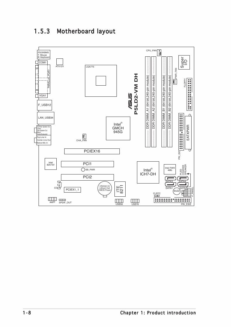
1.5.31.5.31.5.31.5.31.5.3 Motherboard layoutMotherboard layoutMotherboard layoutMotherboard layoutMotherboard layout
Below:Center/Subwoofer
Center:Side Speaker Out
Top:Rear Speaker Out
CR2032 3VLithium Cell
CMOS PowerCD
Su
pe
rI/
O
Intel FWH4Mb
ATX12V
FLO
PP
Y
AAFP
DD
R D
IMM
_A1
(64
bit,2
40-p
in m
odul
e)
SB_PWR
F_P
AN
EL
CH
AS
SIS
USB78USB56
CLRTC
PCI1
Intel®
GMCH945G
Intel®
ICH7-DH
DD
R D
IMM
_A2
(64
bit,2
40-p
in m
odul
e)
DD
R D
IMM
_B1
(64
bit,2
40-p
in m
odul
e)
DD
R D
IMM
_B2
(64
bit,2
40-p
in m
odul
e)
CHA_FAN
CPU_FAN
PR
I_ID
E
EAT
XP
WR
PCI2
SPDIF_OUT
Intel82573V
LGA775
PS/2KBMST: MouseB: Keyboard
Below:Mic In
Center:Line Out
Top:Line In
F_USB12
LAN_USB34
PCIEX1_1
PCIEX16
COM1
PA
RA
LLE
L P
OR
T
VGA1
PLE
D
®
P5
LD
2-V
M D
H
ITE
82
11 SATA1 SATA2
SATA4SATA3
BUZZ
PW
R_F
AN
PRI_EIDE
SP
EA
KE
R

ASUS P5LD2-VM DHASUS P5LD2-VM DHASUS P5LD2-VM DHASUS P5LD2-VM DHASUS P5LD2-VM DH 1 - 91 - 91 - 91 - 91 - 9
1.6.11.6.11.6.11.6.11.6.1 Installing the CPUInstalling the CPUInstalling the CPUInstalling the CPUInstalling the CPUTo install a CPU:
1. Locate the CPU socket on the motherboard.
1.6 Central Processing Unit (CPU)The motherboard comes with a surface mount LGA775 socket designed forthe Intel® Pentium® 4 processor in the 775-land package.
• Your boxed Intel® Pentium® 4 LGA775 processor package shouldcome with installation instructions for the CPU, fan and heatsinkassembly. If the instructions in this section do not match the CPUdocumentation, follow the latter.
• Upon purchase of the motherboard, make sure that the PnP cap ison the socket and the socket pins are not bent. Contact yourretailer immediately if the PnP cap is missing, or if you see anydamage to the PnP cap/socket pins/motherboard components.ASUS will shoulder the cost of repair only if the damage is shipment/transit-related.
• Keep the cap after installing the motherboard. ASUS will processReturn Merchandise Authorization (RMA) requests only if themotherboard comes with the cap on the LGA775 socket.
• The product warranty does not cover damage to the socket pinsresulting from incorrect CPU installation/removal, or misplacement/loss/incorrect removal of the PnP cap.
Before installing the CPU, make sure that the socket box is facingtowards you and the load lever is on your left.
®
P5
LD
2-V
M D
H
P5LD2-VM DH CPU Socket 775

1 -101 -101 -101 -101 -10 Chapter 1 : Product int roduct ionChapter 1 : Product int roduct ionChapter 1 : Product int roduct ionChapter 1 : Product int roduct ionChapter 1 : Product int roduct ion
3. Lift the load lever in the directionof the arrow to a 135º angle.
4. Lift the load plate with yourthumb and forefinger to a 100ºangle (A), then push the PnP capfrom the load plate window toremove (B).
To prevent damage to the socket pins, do not remove the PnP capunless you are installing a CPU.
5. Position the CPU over thesocket, making sure thatthe gold triangle is onthe bottom-left corner ofthe socket. The socketalignment key should fitinto the CPU notch.
2. Press the load lever with your thumb (A) and move it to the left (B)until it is released from the retention tab.
Re ten t i on t abRe ten t i on t abRe ten t i on t abRe ten t i on t abRe ten t i on t ab
Load l e ve rLoad l e ve rLoad l e ve rLoad l e ve rLoad l e ve r
Th i s s i de o f t he camTh i s s i de o f t he camTh i s s i de o f t he camTh i s s i de o f t he camTh i s s i de o f t he cambox shou ld f ace you .box shou ld f ace you .box shou ld f ace you .box shou ld f ace you .box shou ld f ace you .
P nP C apPnP CapPnP CapPnP CapPnP CapA
B
Load p l a t eLoad p l a t eLoad p l a t eLoad p l a t eLoad p l a t e
A
B
A l i gnment keyA l i gnment keyA l i gnment keyA l i gnment keyA l i gnment key
Go ld t r i ang l e ma rkGo ld t r i ang l e ma rkGo ld t r i ang l e ma rkGo ld t r i ang l e ma rkGo ld t r i ang l e ma rk

ASUS P5LD2-VM DHASUS P5LD2-VM DHASUS P5LD2-VM DHASUS P5LD2-VM DHASUS P5LD2-VM DH 1 -111 -111 -111 -111 -11
The CPU fits in only one correct orientation. DO NOT force the CPU intothe socket to prevent bending the connectors on the socket anddamaging the CPU!
6. Close the load plate (A), thenpush the load lever (B) until itsnaps into the retention tab.
A
B
The motherboard supports Intel® Pentium® D or Intel® Pentium® 4LGA775 processors with the Intel® Enhanced Memory 64 Technology(EM64T), Enhanced Intel SpeedStep® Technology (EIST), andHyper-Threading Technology. Refer to the Appendix for moreinformation on these CPU features.

1 -121 -121 -121 -121 -12 Chapter 1 : Product int roduct ionChapter 1 : Product int roduct ionChapter 1 : Product int roduct ionChapter 1 : Product int roduct ionChapter 1 : Product int roduct ion
1.6.21.6.21.6.21.6.21.6.2 Installing the CPU heatsink and fanInstalling the CPU heatsink and fanInstalling the CPU heatsink and fanInstalling the CPU heatsink and fanInstalling the CPU heatsink and fanThe Intel® Pentium® 4 LGA775 processor requires a specially designedheatsink and fan assembly to ensure optimum thermal condition andperformance.
• Install the motherboard to the chassis before you install the CPU fanand heatsink assembly
• When you buy a boxed Intel® Pentium® 4 processor, the packageincludes the CPU fan and heatsink assembly. If you buy a CPUseparately, make sure that you use only Intel®-certifiedmulti-directional heatsink and fan.
• Your Intel® Pentium® 4 LGA775 heatsink and fan assembly comes ina push-pin design and requires no tool to install.
If you purchased a separate CPU heatsink and fan assembly, make surethat a Thermal Interface Material is properly applied to the CPU heatsinkor CPU before you install the heatsink and fan assembly.
To install the CPU heatsink and fan:
1. Place the heatsink on top of theinstalled CPU, making sure thatthe four fasteners match theholes on the motherboard.
Fa s t ene rF a s t ene rF a s t ene rF a s t ene rF a s t ene r
Mothe rboa rd ho l eMothe rboa rd ho l eMothe rboa rd ho l eMothe rboa rd ho l eMothe rboa rd ho l e
Make sure each fastener is oriented as shown, with the narrow groovedirected outward.

ASUS P5LD2-VM DHASUS P5LD2-VM DHASUS P5LD2-VM DHASUS P5LD2-VM DHASUS P5LD2-VM DH 1 -131 -131 -131 -131 -13
Do not forget to connect the CPU fan connector! Hardware monitoringerrors can occur if you fail to plug this connector.
3. When the fan and heatsink assembly is in place, connect the CPU fancable to the connector on the motherboard labeled CPU_FAN.
2. Push down two fasteners at atime in a diagonal sequence tosecure the heatsink and fanassembly in place.
A
A B
B
B
B
AA
®
P5
LD
2-V
M D
H
CPU_FAN
GNDCPU FAN PWR
CPU FAN INCPU FAN PWM
P5LD2-VM DH CPU fan connector
1 -141 -141 -141 -141 -14 Chapter 1 : Product int roduct ionChapter 1 : Product int roduct ionChapter 1 : Product int roduct ionChapter 1 : Product int roduct ionChapter 1 : Product int roduct ion
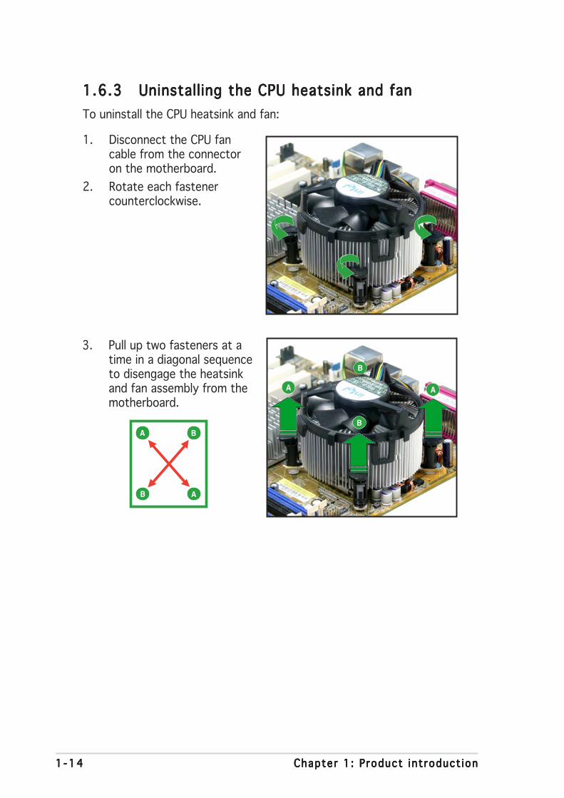
1.6.31.6.31.6.31.6.31.6.3 Uninstalling the CPU heatsink and fanUninstalling the CPU heatsink and fanUninstalling the CPU heatsink and fanUninstalling the CPU heatsink and fanUninstalling the CPU heatsink and fanTo uninstall the CPU heatsink and fan:
1. Disconnect the CPU fancable from the connectoron the motherboard.
2. Rotate each fastenercounterclockwise.
3. Pull up two fasteners at atime in a diagonal sequenceto disengage the heatsinkand fan assembly from themotherboard.
A
A B
B
B
B
A A

ASUS P5LD2-VM DHASUS P5LD2-VM DHASUS P5LD2-VM DHASUS P5LD2-VM DHASUS P5LD2-VM DH 1 -151 -151 -151 -151 -15
4. Remove the heatsink and fanassembly from themotherboard.
5. Rotate each fastenerclockwise to reset theorientation.
The narrow end of thegroove should pointoutward after resetting.(The photo shows thegroove shaded foremphasis.)
Na r row end o f the g rooveNa r row end o f the g rooveNa r row end o f the g rooveNa r row end o f the g rooveNa r row end o f the g roove

1 -161 -161 -161 -161 -16 Chapter 1 : Product int roduct ionChapter 1 : Product int roduct ionChapter 1 : Product int roduct ionChapter 1 : Product int roduct ionChapter 1 : Product int roduct ion
1.7 System memory
1.7.11.7.11.7.11.7.11.7.1 OverviewOverviewOverviewOverviewOverviewThe motherboard comes with four Double Data Rate 2 (DDR2) Dual InlineMemory Modules (DIMM) sockets.
A DDR2 module has the same physical dimensions as a DDR DIMM but has a240-pin footprint compared to the 184-pin DDR DIMM. DDR2 DIMMs arenotched differently to prevent installation on a DDR DIMM socket.
The figure illustrates the location of the DDR2 DIMM sockets:
®
P5L
D2-V
M D
H
P5LD2-VM DH 240-pin DDR2 DIMM sockets
DIM
M_A
2
DIM
M_A
1
DIM
M_B
2
DIM
M_B
1
Channe lChanne lChanne lChanne lChanne l S o c k e t sS o c k e t sS o c k e t sS o c k e t sS o c k e t s
Channe l AChanne l AChanne l AChanne l AChanne l A D IMM_A1 and D IMM_A2D IMM_A1 and D IMM_A2D IMM_A1 and D IMM_A2D IMM_A1 and D IMM_A2D IMM_A1 and D IMM_A2
Channe l BChanne l BChanne l BChanne l BChanne l B D IMM_B1 and D IMM_B2D IMM_B1 and D IMM_B2D IMM_B1 and D IMM_B2D IMM_B1 and D IMM_B2D IMM_B1 and D IMM_B2
1.7.21.7.21.7.21.7.21.7.2 Memory ConfigurationsMemory ConfigurationsMemory ConfigurationsMemory ConfigurationsMemory Configurations
• IF you installed four 1GB memory modules, the system may detectless than 3GB of total memory because of address space allocationfor other critical functions. This limitation applies to Windows XP32-bit version operating system since it does not support PAE(Physical Address Extension) mode.
• IF you install Windows XP 32-bit version operating system, werecommend that you install less than 3GB of total memory.
• For dual-channel configuration, the total size of memory module(s)installed per channel must be the same for better performance(DIMM_A1+DIMM_A2=DIMM_B1+DIMM_B2).

ASUS P5LD2-VM DHASUS P5LD2-VM DHASUS P5LD2-VM DHASUS P5LD2-VM DHASUS P5LD2-VM DH 1 -171 -171 -171 -171 -17
1.7.31.7.31.7.31.7.31.7.3 DDR2 Qualified Vendors ListDDR2 Qualified Vendors ListDDR2 Qualified Vendors ListDDR2 Qualified Vendors ListDDR2 Qualified Vendors ListThe following table lists the memory modules that have been tested andqualified for use with this motherboard. Visit the ASUS website(www.asus.com) for the latest DDR2 DIMM modules for this motherboard.
DDR2 533 Qualified Vendors ListDDR2 533 Qualified Vendors ListDDR2 533 Qualified Vendors ListDDR2 533 Qualified Vendors ListDDR2 533 Qualified Vendors List DIMM support
S i z e S i z e S i z e S i z e S i z e V e n d o rV e n d o rV e n d o rV e n d o rV e n d o r M o d e l M o d e l M o d e l M o d e l M o d e l B r a n d S i d e ( s ) C o m p o n e n t B r a n d S i d e ( s ) C o m p o n e n t B r a n d S i d e ( s ) C o m p o n e n t B r a n d S i d e ( s ) C o m p o n e n t B r a n d S i d e ( s ) C o m p o n e n t AAAAA B CB CB CB CB C
512MB SAMSUNG M378T6553BG0-CD5 N/A SS K4T51083QB-GCD5 • • •256MB SAMSUNG M378T3253FG0-CD5 N/A SS K4T56083QF-GCD5 • • •512MB SAMSUNG M378T6453FG0-CD5 N/A DS K4T56083QF-GCD5 • • •512MB Infineon HYS64T64000GU-3.7-A Infineon SS HYB18T512800AC37 • •256MB Infineon HYS64T32000HU-3.7-A Infineon SS HYB18T512160AF-3.7 • • •1024MB Infineon HYS64T128020HU-3.7-A Infineon DS HYB18T512800AF37 • • •512MB Infineon HYS64T64000HU-3.7-A Infineon SS HYB18T512800AF37 • • •512MB CORSAIR CM2X512-4200 N/A DS N/A • • •512MB MICRON MT16HTF6464AG-53EB2 MICRON DS 4FBIID9BQM • •1024MB MICRON MT16HTF12864AY-53EA1 MICRON DS 4JAIID9CRZ • • •256MB MICRON MT8HTF3264AY-53EB3 MICRON SS 4FBIID9CHM • •512MB MICRON MT16HTF6464AY-53EB2 MICRON DS 4FBIID9CHM • • •1024MB Kingston D6408TE7BL-37 N/A DS E5108AB-5C-E • • •256MB Kingston E5116AB-5C-E N/A SS HYB18T512160AC-3.7 • • •512MB Kingston HY5PS56821F-C4 ELPIDA SS E5108AB-5C-E • • •512MB Hynix HYMP564U648-C4 N/A SS HY5PS12821F-C4 • • •512MB Hynix HY5PS1282AFP-C3 N/A SS HYMP564U64AP8-C3 • • •1024MB Hynix HYMP512U648-C4 N/A DS HY5PS12821FP-C4 • • •512MB ELPIDA EBE51UD8ABFA-5C ELPIDA DS E5108AB-5C-E • • •1024MB ELPIDA EBE11UD8ABFA-5C-E ELPIDA DS E5108AB-5C-E • • •
• When using one DDR DIMM module, install into DIMM_B1 slot only.• When using two DDR DIMM modules, install into DIMM_A1 and
DIMM_B1 slots only.• Always install DIMMs with the same CAS latency. For optimum
compatibility, it is recommended that you obtain memory modulesfrom the same vendor. Refer to the memory Qualified Vendors Liston the next page for details.
• Due to CPU limitation, DIMM modules with 128 Mb memory chips ordouble-sided x16 memory chips are not supported in this motherboard.

1 -181 -181 -181 -181 -18 Chapter 1 : Product int roduct ionChapter 1 : Product int roduct ionChapter 1 : Product int roduct ionChapter 1 : Product int roduct ionChapter 1 : Product int roduct ion
DDR2 667 Qualified Vendors ListDDR2 667 Qualified Vendors ListDDR2 667 Qualified Vendors ListDDR2 667 Qualified Vendors ListDDR2 667 Qualified Vendors List
S ide(s) : SS - S ide(s) : SS - S ide(s) : SS - S ide(s) : SS - S ide(s) : SS - Single Sided D S -D S -D S -D S -D S - Double SidedD IMM Support :D IMM Support :D IMM Support :D IMM Support :D IMM Support :AAAAA - supports one module inserted into either slot, in a Single-channel memory
configuration.BBBBB - supports on pair of modules inserted into either the yellow slots or the black
slots as one pair of Dual-channel memory configuration.CCCCC - support for 4 modules inserted into the yellow and black slots as two pairs of
Dual-channel memory configuration.
512MB Hynix HYMP564U64AP8-Y5 Hynix SS HY5PS12821AFP-Y5 • • •1024MB Hynix HYMP512U64AP8-Y4 Hynix DS HY5PS12821AFP-Y4 • • •512MB Hynix HYMP564U64AP8-Y4 Hynix SS HY5PS12821AFP-Y4 • • •256MB MICRON MT8HTF3264AY-667B5 MICRON SS 4SB42D9CZM • • •256MB MICRON MT8HTF3264AY-667B6 MICRON SS 5FB42D9DPN • • •512MB Infineon HYS64T64000HU-3S-A Infineon SS HYB18T512800AF3S • • •256MB Infineon HYS64T32000HU-3S-A Infineon SS HYB18T512160AF-3S • • •1024MB Infineon HYS64T128020HU-3S-A Infineon DS HYB18T512800AF3S • • •256MB ELPIDA EBE25UC8ABFA-6E-E ELPIDA SS E2508AB-GE-E • • •512MB ELPIDA EBE51UD8AEFA-6E-E ELPIDA SS E5108AE-GE-E • • •1024MB ELPIDA EBE11UD8AEFA-6E-E N/A DS N/A • • •
DIMM support S i z e S i z e S i z e S i z e S i z e V e n d o rV e n d o rV e n d o rV e n d o rV e n d o r M o d e l M o d e l M o d e l M o d e l M o d e l B r a n d S i d e ( s ) C o m p o n e n t B r a n d S i d e ( s ) C o m p o n e n t B r a n d S i d e ( s ) C o m p o n e n t B r a n d S i d e ( s ) C o m p o n e n t B r a n d S i d e ( s ) C o m p o n e n t AAAAA B CB CB CB CB C

ASUS P5LD2-VM DHASUS P5LD2-VM DHASUS P5LD2-VM DHASUS P5LD2-VM DHASUS P5LD2-VM DH 1 -191 -191 -191 -191 -19
1.7.41.7.41.7.41.7.41.7.4 Installing a DIMMInstalling a DIMMInstalling a DIMMInstalling a DIMMInstalling a DIMM
Unplug the power supply before adding or removing DIMMs or othersystem components. Failure to do so can cause severe damage to boththe motherboard and the components.
To install a DIMM:
1. Unlock a DIMM socket bypressing the retaining clipsoutward.
2. Align a DIMM on the socketsuch that the notch on theDIMM matches the break onthe socket.
3. Firmly insert the DIMM into thesocket until the retaining clipssnap back in place and theDIMM is properly seated.
1.7.51.7.51.7.51.7.51.7.5 Removing a DIMMRemoving a DIMMRemoving a DIMMRemoving a DIMMRemoving a DIMMFollow these steps to remove a DIMM.
1. Simultaneously press the retainingclips outward to unlock the DIMM.
2. Remove the DIMM from the socket.
• A DDR2 DIMM is keyed with a notch so that it fits in only onedirection. Do not force a DIMM into a socket to avoid damaging theDIMM.
• The DDR2 DIMM sockets do not support DDR DIMMs. DO not installDDR DIMMs to the DDR2 DIMM sockets.
Support the DIMM lightly withyour fingers when pressing theretaining clips. The DIMM mightget damaged when it flips outwith extra force.
Un locked re ta i n i ng c l i pUn locked re ta i n i ng c l i pUn locked re ta i n i ng c l i pUn locked re ta i n i ng c l i pUn locked re ta i n i ng c l i p
DDR2 D IMM no tchDDR2 D IMM no tchDDR2 D IMM no tchDDR2 D IMM no tchDDR2 D IMM notch
1
2
3
DDR2 D IMM no tchDDR2 D IMM no tchDDR2 D IMM no tchDDR2 D IMM no tchDDR2 D IMM no tch1
2
1

1 -201 -201 -201 -201 -20 Chapter 1 : Product int roduct ionChapter 1 : Product int roduct ionChapter 1 : Product int roduct ionChapter 1 : Product int roduct ionChapter 1 : Product int roduct ion
1.8 Expansion slotsIn the future, you may need to install expansion cards. The followingsub-sections describe the slots and the expansion cards that they support.
1.8.11.8.11.8.11.8.11.8.1 Installing an expansion cardInstalling an expansion cardInstalling an expansion cardInstalling an expansion cardInstalling an expansion cardTo install an expansion card:
1. Before installing the expansion card, read the documentation thatcame with it and make the necessary hardware settings for the card.
2. Remove the system unit cover (if your motherboard is alreadyinstalled in a chassis).
3. Remove the bracket opposite the slot that you intend to use. Keepthe screw for later use.
4. Align the card connector with the slot and press firmly until the card iscompletely seated on the slot.
5. Secure the card to the chassis with the screw you removed earlier.6. Replace the system cover.
1.8.21.8.21.8.21.8.21.8.2 Configuring an expansion cardConfiguring an expansion cardConfiguring an expansion cardConfiguring an expansion cardConfiguring an expansion cardAfter installing the expansion card, configure it by adjusting the softwaresettings.
1. Turn on the system and change the necessary BIOS settings, if any.See Chapter 2 for information on BIOS setup.
2. Assign an IRQ to the card. Refer to the tables on the next page.3. Install the software drivers for the expansion card.
Make sure to unplug the power cord before adding or removingexpansion cards. Failure to do so may cause you physical injury anddamage motherboard components.
ASUS P5LD2-VM DHASUS P5LD2-VM DHASUS P5LD2-VM DHASUS P5LD2-VM DHASUS P5LD2-VM DH 1 -211 -211 -211 -211 -21
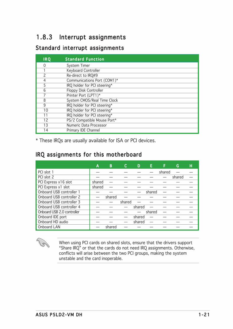
1.8.31.8.31.8.31.8.31.8.3 Interrupt assignmentsInterrupt assignmentsInterrupt assignmentsInterrupt assignmentsInterrupt assignmentsStandard interrupt assignmentsStandard interrupt assignmentsStandard interrupt assignmentsStandard interrupt assignmentsStandard interrupt assignments
I R QI R QI R QI R QI R Q S tanda rd Funct i on S tanda rd Funct i on S tanda rd Funct i on S tanda rd Funct i on S tanda rd Funct i on0 System Timer1 Keyboard Controller2 Re-direct to IRQ#94 Communications Port (COM1)*5 IRQ holder for PCI steering*6 Floppy Disk Controller7 Printer Port (LPT1)*8 System CMOS/Real Time Clock9 IRQ holder for PCI steering*10 IRQ holder for PCI steering*11 IRQ holder for PCI steering*12 PS/2 Compatible Mouse Port*13 Numeric Data Processor14 Primary IDE Channel
* These IRQs are usually available for ISA or PCI devices.
IRQ assignments for this motherboardIRQ assignments for this motherboardIRQ assignments for this motherboardIRQ assignments for this motherboardIRQ assignments for this motherboard
AAAAA BBBBB CCCCC DDDDD EEEEE FFFFF GGGGG HHHHHPCI slot 1 — — — — — shared — —PCI slot 2 — — — — — — shared —PCI Express x16 slot shared — — — — — — —PCI Express x1 slot shared — — — — — — —Onboard USB controller 1 — — — — shared — — —Onboard USB controller 2 — shared — — — — — —Onboard USB controller 3 — — shared — — — — —Onboard USB controller 4 — — — shared — — — —Onboard USB 2.0 controller — — — — shared — — —Onboard IDE port — — — shared — — — —Onboard HD audio — — — shared — — — —Onboard LAN — shared — — — — — —
When using PCI cards on shared slots, ensure that the drivers support“Share IRQ” or that the cards do not need IRQ assignments. Otherwise,conflicts will arise between the two PCI groups, making the systemunstable and the card inoperable.

1 -221 -221 -221 -221 -22 Chapter 1 : Product int roduct ionChapter 1 : Product int roduct ionChapter 1 : Product int roduct ionChapter 1 : Product int roduct ionChapter 1 : Product int roduct ion
1.8.41.8.41.8.41.8.41.8.4 PCI slotsPCI slotsPCI slotsPCI slotsPCI slotsThe PCI slots support cards such asa LAN card, SCSI card, USB card,and other cards that comply withPCI specifications. The figure showsa LAN card installed on a PCI slot.
1.8.51.8.51.8.51.8.51.8.5 PCI Express x16PCI Express x16PCI Express x16PCI Express x16PCI Express x16This motherboard supports one PCIExpress x16 graphics card. Thefigure shows a graphics cardinstalled on the PCI Express x16slot.
1.8.61.8.61.8.61.8.61.8.6 PCI Express x1PCI Express x1PCI Express x1PCI Express x1PCI Express x1This motherboard supports PCIExpress x1 network cards, SCSIcards and other cards that complywith the PCI Express specifications.The figure shows a network cardinstalled on the PCI Express x1 slot.

ASUS P5LD2-VM DHASUS P5LD2-VM DHASUS P5LD2-VM DHASUS P5LD2-VM DHASUS P5LD2-VM DH 1 -231 -231 -231 -231 -23
1.9 Jumpers1 .1 .1 .1 .1 . C lear RTC RAM (CLRTC)Clear RTC RAM (CLRTC)Clear RTC RAM (CLRTC)Clear RTC RAM (CLRTC)Clear RTC RAM (CLRTC)
This jumper allows you to clear the Real Time Clock (RTC) RAM inCMOS. You can clear the CMOS memory of date, time, and systemsetup parameters by erasing the CMOS RTC RAM data. The onboardbutton cell battery powers the RAM data in CMOS, which includesystem setup information such as system passwords.
To erase the RTC RAM:
1. Turn OFF the computer and unplug the power cord.2. Remove the onboard battery.3. Move the jumper cap from pins 1-2 (default) to pins 2-3. Keep the
cap on pins 2-3 for about 5~10 seconds, then move the cap back topins 1-2.
4. Re-install the battery.5. Plug the power cord and turn ON the computer.6. Hold down the <Del> key during the boot process and enter BIOS
setup to re-enter data.
Except when clearing the RTC RAM, never remove the cap on CLRTCjumper default position. Removing the cap will cause system boot failure!
You do not need to clear the RTC when the system hangs due tooverclocking. For system failure due to overclocking, use the C.P.R. (CPUParameter Recall) feature. Shut down and reboot the system so the BIOScan automatically reset parameter settings to default values.
®
P5L
D2-V
M D
H
P5LD2-VM DH Clear RTC RAM
CLRTC
Normal Clear CMOS(Default)
1 2 2 3

1 -241 -241 -241 -241 -24 Chapter 1 : Product int roduct ionChapter 1 : Product int roduct ionChapter 1 : Product int roduct ionChapter 1 : Product int roduct ionChapter 1 : Product int roduct ion
4 .4 .4 .4 .4 . Rear Speaker Out port (orange).Rear Speaker Out port (orange).Rear Speaker Out port (orange).Rear Speaker Out port (orange).Rear Speaker Out port (orange). This port connects the rearspeakers on a 4-channel, 6-channel, or 8-channel audio configuration.
5 .5 .5 .5 .5 . S ide Speaker Out port (b lack).S ide Speaker Out port (b lack).S ide Speaker Out port (b lack).S ide Speaker Out port (b lack).S ide Speaker Out port (b lack). This port connects the sidespeakers in an 8-channel audio configuration.
6 .6 .6 .6 .6 . L ine In port ( l ight b lue).L ine In port ( l ight b lue).L ine In port ( l ight b lue).L ine In port ( l ight b lue).L ine In port ( l ight b lue). This port connects a tape, CD, DVDplayer, or other audio sources.
7 .7 .7 .7 .7 . L ine Out port ( l ime).L ine Out port ( l ime).L ine Out port ( l ime).L ine Out port ( l ime).L ine Out port ( l ime). This port connects a headphone or aspeaker. In 4-channel, 6-channel, and 8-channel configuration, thefunction of this port becomes Front Speaker Out.
LAN port LED indicationsLAN port LED indicationsLAN port LED indicationsLAN port LED indicationsLAN port LED indications ACT/L INK LED ACT/L INK LED ACT/L INK LED ACT/L INK LED ACT/L INK LED SPEED LED SPEED LED SPEED LED SPEED LED SPEED LED
S t a t u sS t a t u sS t a t u sS t a t u sS t a t u s Desc r i p t i onDesc r i p t i onDesc r i p t i onDesc r i p t i onDesc r i p t i on S t a t u sS t a t u sS t a t u sS t a t u sS t a t u s Desc r i p t i onDesc r i p t i onDesc r i p t i onDesc r i p t i onDesc r i p t i onOFF No link OFF 10 Mbps connectionGREEN Linked ORANGE 100 Mbps connectionBLINKING Data activity GREEN 1 Gbps connection
1.10 Connectors
1.10.11.10.11.10.11.10.11.10.1 Rear panel connectorsRear panel connectorsRear panel connectorsRear panel connectorsRear panel connectors
1 .1 .1 .1 .1 . PS/2 mouse port (green).PS/2 mouse port (green).PS/2 mouse port (green).PS/2 mouse port (green).PS/2 mouse port (green). This port is for a PS/2 mouse.2 .2 .2 .2 .2 . Para l le l port .Para l le l port .Para l le l port .Para l le l port .Para l le l port . This 25-pin port connects a parallel printer, a scanner,
or other devices.3 .3 .3 .3 .3 . LAN (RJ-45) port .LAN (RJ-45) port .LAN (RJ-45) port .LAN (RJ-45) port .LAN (RJ-45) port . This port allows Gigabit connection to a Local
Area Network (LAN) through a network hub. Refer to the table belowfor the LAN port LED indications.
1
14 10
2 3
13
6
7
8
4 5
912 11

ASUS P5LD2-VM DHASUS P5LD2-VM DHASUS P5LD2-VM DHASUS P5LD2-VM DHASUS P5LD2-VM DH 1 -251 -251 -251 -251 -25
10 .10 .10 .10 .10 . USB 2.0 ports 3 and 4.USB 2.0 ports 3 and 4.USB 2.0 ports 3 and 4.USB 2.0 ports 3 and 4.USB 2.0 ports 3 and 4. These two 4-pin Universal Serial Bus(USB) ports are available for connecting USB 2.0 devices.
11 .11 .11 .11 .11 . USB 2.0 ports 1 and 2.USB 2.0 ports 1 and 2.USB 2.0 ports 1 and 2.USB 2.0 ports 1 and 2.USB 2.0 ports 1 and 2. These two 4-pin Universal Serial Bus(USB) ports are available for connecting USB 2.0 devices.
12 .12 .12 .12 .12 . VGA port .VGA port .VGA port .VGA port .VGA port . This 15-pin VGA port connects to a VGA monitor.13 .13 .13 .13 .13 . Ser ia l connector . Ser ia l connector . Ser ia l connector . Ser ia l connector . Ser ia l connector . This 9-pin COM1 port is for serial devices.14 .14 .14 .14 .14 . PS/2 keyboard port (purple) .PS/2 keyboard port (purple) .PS/2 keyboard port (purple) .PS/2 keyboard port (purple) .PS/2 keyboard port (purple) . This port is for a PS/2 keyboard.
8 .8 .8 .8 .8 . Microphone port (p ink). Microphone port (p ink). Microphone port (p ink). Microphone port (p ink). Microphone port (p ink). This port connects a microphone.9 .9 .9 .9 .9 . Center/Subwoofer port (gray).Center/Subwoofer port (gray).Center/Subwoofer port (gray).Center/Subwoofer port (gray).Center/Subwoofer port (gray). This port connects the center/
subwoofer speakers.
Audio 2, 4, 6, or 8-channel conf igurat ionAudio 2, 4, 6, or 8-channel conf igurat ionAudio 2, 4, 6, or 8-channel conf igurat ionAudio 2, 4, 6, or 8-channel conf igurat ionAudio 2, 4, 6, or 8-channel conf igurat ion
Light B lueL ight B lueL ight B lueL ight B lueL ight B lue Line In Line In Line In Line InL imeL imeL imeL imeL ime Line Out Front Speaker Out Front Speaker Out Front Speaker OutP i n kP i n kP i n kP i n kP i n k Mic In Mic In Mic In Mic InOrangeOrangeOrangeOrangeOrange — Rear Speaker Out Rear Speaker Out Rear Speaker OutB l ackB l ackB l ackB l ackB l ack — — — Side Speaker OutG r ayG r ayG r ayG r ayG r ay — — Center/Subwoofer Center/Subwoofer
P o r tP o r tP o r tP o r tP o r t 2 - channe l2 - channe l2 - channe l2 - channe l2 - channe l 4 - channe l4 - channe l4 - channe l4 - channe l4 - channe l 6 - channe l6 - channe l6 - channe l6 - channe l6 - channe l 8 - channe l8 - channe l8 - channe l8 - channe l8 - channe l(Headse t )(Headse t )(Headse t )(Headse t )(Headse t )
Refer to the audio configuration table below for the function of theaudio ports in 2, 4, 6, or 8-channel configuration.

1 -261 -261 -261 -261 -26 Chapter 1 : Product int roduct ionChapter 1 : Product int roduct ionChapter 1 : Product int roduct ionChapter 1 : Product int roduct ionChapter 1 : Product int roduct ion
1.10.21.10.21.10.21.10.21.10.2 Internal connectorsInternal connectorsInternal connectorsInternal connectorsInternal connectors
1 .1 .1 .1 .1 . F loppy disk dr ive connector (34-1 pin FLOPPY)Floppy disk dr ive connector (34-1 pin FLOPPY)Floppy disk dr ive connector (34-1 pin FLOPPY)Floppy disk dr ive connector (34-1 pin FLOPPY)Floppy disk dr ive connector (34-1 pin FLOPPY)This connector is for the provided floppy disk drive (FDD) signal cable.Insert one end of the cable to this connector, then connect the otherend to the signal connector at the back of the floppy disk drive.
Pin 5 on the connector is removed to prevent incorrect cable connectionwhen using an FDD cable with a covered Pin 5.
®
P5
LD
2-V
M D
H
NOTE: Orient the red markings onthe floppy ribbon cable to PIN 1.
P5LD2-VM DH Floppy disk drive connector
PIN 1
FLOPPY
2 .2 .2 .2 .2 . Pr imary IDE connector (40-1 pin PRI_IDE)Pr imary IDE connector (40-1 pin PRI_IDE)Pr imary IDE connector (40-1 pin PRI_IDE)Pr imary IDE connector (40-1 pin PRI_IDE)Pr imary IDE connector (40-1 pin PRI_IDE)These connectors are for Ultra DMA 133/100/66 signal cables. There arethree interfaces on each Ultra DMA 133/100/66 signal cable: blue, black,and gray. Connect the blue interface into the motherboard’s IDE connector,then select one of the following modes to configure your hard disk drive(s).
Cable Se lect Mode Cable Se lect Mode Cable Se lect Mode Cable Se lect Mode Cable Se lect Mode - use this mode to select the operating mode bycable connectors.
No. of drives Drive type Drive jumper Cable connector
1 With OS black
2 With OS Cable select black
Without OS gray
Jumper Se lect Mode Jumper Se lect Mode Jumper Se lect Mode Jumper Se lect Mode Jumper Se lect Mode - use this mode to select the operating mode byhard disk drive jumper.
No, of drives Drive type Drive jumper Cable connector
1 With OS Master
2 With OS Master black or gray
Without OS Slave

ASUS P5LD2-VM DHASUS P5LD2-VM DHASUS P5LD2-VM DHASUS P5LD2-VM DHASUS P5LD2-VM DH 1 -271 -271 -271 -271 -27
®
P5
LD
2-V
M D
H
P5LD2-VM DH IDE connector
NOTE: Orient the red markings(usually zigzag) on the IDEribbon cable to PIN 1.
PRI_IDE
PIN 1

1 -281 -281 -281 -281 -28 Chapter 1 : Product int roduct ionChapter 1 : Product int roduct ionChapter 1 : Product int roduct ionChapter 1 : Product int roduct ionChapter 1 : Product int roduct ion
3 .3 .3 .3 .3 . ITE IDE connector (40-1 pin PRI_EIDE [red])ITE IDE connector (40-1 pin PRI_EIDE [red])ITE IDE connector (40-1 pin PRI_EIDE [red])ITE IDE connector (40-1 pin PRI_EIDE [red])ITE IDE connector (40-1 pin PRI_EIDE [red])Supported by the ITE8211F controller, this connector is for Ultra ATA133/100/66 signal cables. This connector supports two IDE hard diskdrives for easier data storage.
4 .4 .4 .4 .4 . Ser ia l ATA connectorsSer ia l ATA connectorsSer ia l ATA connectorsSer ia l ATA connectorsSer ia l ATA connectors(7-pin SATA1, SATA2, SATA3, SATA4)(7-pin SATA1, SATA2, SATA3, SATA4)(7-pin SATA1, SATA2, SATA3, SATA4)(7-pin SATA1, SATA2, SATA3, SATA4)(7-pin SATA1, SATA2, SATA3, SATA4)These connectors are for the Serial ATA signal cables for Serial ATAhard disk drives.
Install the Windows® 2000 Service Pack 4 or the Windows® XP ServicePack1 or later before using Serial ATA.
®
P5
LD
2-V
M D
H
P5LD2-VM DH PRI_EIDE connectorNOTE: Orient the red markings(usually zigzag) on the IDEcable to PIN 1.
PRI_EIDEPIN 1
®
P5
LD
2-V
M D
H
P5LD2-VM DH SATA connectors
SATA1 SATA2
GN
DR
SAT
A_T
XP
4R
SAT
A_T
XN
4G
ND
RS
ATA
_RX
P4
RS
ATA
_RX
N4
GN
D
GN
DR
SAT
A_T
XP
3R
SAT
A_T
XN
3G
ND
RS
ATA
_RX
P3
RS
ATA
_RX
N3
GN
D
GN
DR
SAT
A_T
XP
2R
SAT
A_T
XN
2G
ND
RS
ATA
_RX
P2
RS
ATA
_RX
N2
GN
D
GN
DR
SAT
A_T
XP
1R
SAT
A_T
XN
1G
ND
RS
ATA
_RX
P1
RS
ATA
_RX
N1
GN
D
SATA3 SATA4

ASUS P5LD2-VM DHASUS P5LD2-VM DHASUS P5LD2-VM DHASUS P5LD2-VM DHASUS P5LD2-VM DH 1 -291 -291 -291 -291 -29
6 .6 .6 .6 .6 . CPU, Power and Chass is fan connectorsCPU, Power and Chass is fan connectorsCPU, Power and Chass is fan connectorsCPU, Power and Chass is fan connectorsCPU, Power and Chass is fan connectors(4-pin CPU_FAN, 3-pin PWR_RAN, 3-pin CHA_FAN)(4-pin CPU_FAN, 3-pin PWR_RAN, 3-pin CHA_FAN)(4-pin CPU_FAN, 3-pin PWR_RAN, 3-pin CHA_FAN)(4-pin CPU_FAN, 3-pin PWR_RAN, 3-pin CHA_FAN)(4-pin CPU_FAN, 3-pin PWR_RAN, 3-pin CHA_FAN)The fan connectors support cooling fans of 350mA~740mA (8.88Wmax.) or a total of 1A~2.22A (26.64W max.) at +12V. Connect the fancables to the fan connectors on the motherboard, making sure that theblack wire of each cable matches the ground pin of the connector.
Do not forget to connect the fan cables to the fan connectors.Insufficient air flow inside the system may damage the motherboardcomponents. These are not jumpers! DO NOT place jumper caps on thefan connectors.
5 .5 .5 .5 .5 . Speaker connector (4-pin SPEAKER)Speaker connector (4-pin SPEAKER)Speaker connector (4-pin SPEAKER)Speaker connector (4-pin SPEAKER)Speaker connector (4-pin SPEAKER)
This 4-pin connector is for the chassis-mounted system warningspeaker. The speaker allows you to hear system beeps and warnings.
®
P5
LD
2-V
M D
H
P5LD2-VM DH Speaker out connector
SPEAKER+5V
1
GND
Speak OutGND
®
P5L
D2-V
M D
H
P5LD2-VM DH Fan connectors
PWR_FANGND
Rotation+12V
CPU_FAN
GNDCPU FAN PWR
CPU FAN INCPU FAN PWM
CHA_FANGND
Rotation+12V

1 -301 -301 -301 -301 -30 Chapter 1 : Product int roduct ionChapter 1 : Product int roduct ionChapter 1 : Product int roduct ionChapter 1 : Product int roduct ionChapter 1 : Product int roduct ion
7 .7 .7 .7 .7 . Dig ita l Audio connector (4-1 pin SPDIF_OUT)Dig ita l Audio connector (4-1 pin SPDIF_OUT)Dig ita l Audio connector (4-1 pin SPDIF_OUT)Dig ita l Audio connector (4-1 pin SPDIF_OUT)Dig ita l Audio connector (4-1 pin SPDIF_OUT)This connector is for the S/PDIF audio module to allow digital soundoutput. Connect one end of the S/PDIF audio cable to this connectorand the other end to the S/PDIF module.
The S/PDIF out module is purchased separately.
8 .8 .8 .8 .8 . Power LED connector (3-pin PLED)Power LED connector (3-pin PLED)Power LED connector (3-pin PLED)Power LED connector (3-pin PLED)Power LED connector (3-pin PLED)
This 3-pin connector is for the system power LED. The system powerLED lights up when you turn on the system power, and blinks whenthe system is in sleep mode.
®
P5
LD
2-V
M D
H
P5LD2-VM DH Digital audio connector+
5V
SP
DIF
OU
TG
ND
SPDIF_OUT®
P5
LD
2-V
M D
H
P5LD2-VM DH Power LED connector
PLED
PLED+1
NCPLED-
ASUS P5LD2-VM DHASUS P5LD2-VM DHASUS P5LD2-VM DHASUS P5LD2-VM DHASUS P5LD2-VM DH 1 -311 -311 -311 -311 -31
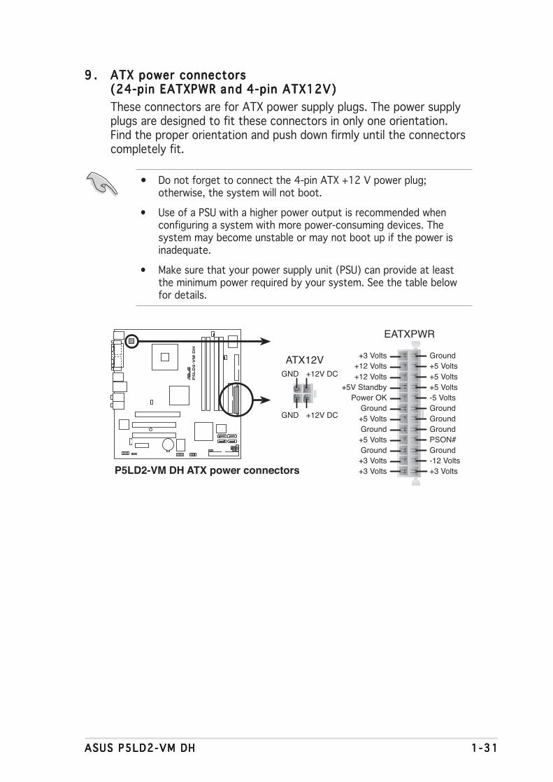
9 .9 .9 .9 .9 . ATX power connectorsATX power connectorsATX power connectorsATX power connectorsATX power connectors(24-pin EATXPWR(24-pin EATXPWR(24-pin EATXPWR(24-pin EATXPWR(24-pin EATXPWR and and and and and 4-pin ATX12V)4-pin ATX12V)4-pin ATX12V)4-pin ATX12V)4-pin ATX12V)These connectors are for ATX power supply plugs. The power supplyplugs are designed to fit these connectors in only one orientation.Find the proper orientation and push down firmly until the connectorscompletely fit.
• Do not forget to connect the 4-pin ATX +12 V power plug;otherwise, the system will not boot.
• Use of a PSU with a higher power output is recommended whenconfiguring a system with more power-consuming devices. Thesystem may become unstable or may not boot up if the power isinadequate.
• Make sure that your power supply unit (PSU) can provide at leastthe minimum power required by your system. See the table belowfor details.
®
P5
LD
2-V
M D
H
P5LD2-VM DH ATX power connectors
EATXPWR
ATX12V
+3 Volts+3 VoltsGround+5 Volts
+5 VoltsGround
GroundPower OK
+5V Standby+12 Volts
-5 Volts
+5 Volts
+3 Volts-12 VoltsGround
GroundGroundPSON#
Ground
+5 Volts
+12 Volts+3 Volts
+5 VoltsGround
+12V DC
GND
GND
+12V DC

1 -321 -321 -321 -321 -32 Chapter 1 : Product int roduct ionChapter 1 : Product int roduct ionChapter 1 : Product int roduct ionChapter 1 : Product int roduct ionChapter 1 : Product int roduct ion
10 .10 .10 .10 .10 . Opt ica l dr ive audio connector (4-pin CD)Optica l dr ive audio connector (4-pin CD)Optica l dr ive audio connector (4-pin CD)Optica l dr ive audio connector (4-pin CD)Optica l dr ive audio connector (4-pin CD)This connector is for the 4-pin audio cable that connects to the audioconnector at the back of the optical drive.
Enable the CD-IN function in the audio utility when using thisconnector.
11 .11 .11 .11 .11 . USB connectors (10-1 pin USB56, USB78)USB connectors (10-1 pin USB56, USB78)USB connectors (10-1 pin USB56, USB78)USB connectors (10-1 pin USB56, USB78)USB connectors (10-1 pin USB56, USB78)These connectors are for USB 2.0 ports. Connect the optionalUSB module cable to any of these connectors, then install the moduleto a slot opening at the back of the system chassis. These USBconnectors comply with USB 2.0 specification that supports up to480 Mbps connection speed.
®
P5L
D2-V
M D
H
P5LD2-VM DH CD audio connector
CDRight Audio Channel
Left Audio ChannelGroundGround
®
P5L
D2-V
M D
H
P5LD2-VM DH USB 2.0 connectors
USB56
US
B+
5VU
SB
_P6-
US
B_P
6+G
ND
NC
US
B+
5VU
SB
_P5-
US
B_P
5+G
ND
1USB78
US
B+
5VU
SB
_P8-
US
B_P
8+G
ND
NC
US
B+
5VU
SB
_P7-
US
B_P
7+G
ND
1

ASUS P5LD2-VM DHASUS P5LD2-VM DHASUS P5LD2-VM DHASUS P5LD2-VM DHASUS P5LD2-VM DH 1 -331 -331 -331 -331 -33
13 .13 .13 .13 .13 . Chass is intrus ion connector (4-1 pin CHASSIS)Chass is intrus ion connector (4-1 pin CHASSIS)Chass is intrus ion connector (4-1 pin CHASSIS)Chass is intrus ion connector (4-1 pin CHASSIS)Chass is intrus ion connector (4-1 pin CHASSIS)This connector is for a chassis-mounted intrusion detection sensor orswitch. Connect one end of the chassis intrusion sensor or switchcable to this connector. The chassis intrusion sensor or switch sends ahigh-level signal to this connector when a chassis component isremoved or replaced. The signal is then generated as a chassisintrusion event.
By default, the pins labeled “Chassis Signal” and “Ground” are shortedwith a jumper cap. Remove the jumper caps only when you intend touse the chassis intrusion detection feature.
12 .12 .12 .12 .12 . Front panel audio connector (10-1 pin AAFP)Front panel audio connector (10-1 pin AAFP)Front panel audio connector (10-1 pin AAFP)Front panel audio connector (10-1 pin AAFP)Front panel audio connector (10-1 pin AAFP)This connector is for a chassis-mounted front panel audio I/O modulethat supports either HD Audio or legacy AC’97 audio standard.
It is recommended that you connect a high-definition front panel audiomodule to this connector to avail of the motherboard’s high-definitionaudio capability.
®
P5
LD
2-V
M D
H
P5LD2-VM DH Analog front panel connector
AAFPLegacy AC’97
compliant definitionAzalia
compliant definition
SE
NS
E2_
RE
TU
R
PO
RT
1 L
PO
RT
2 R
PO
RT
2 L
SE
NS
E1_
RE
TU
RS
EN
SE
_SE
ND
PO
RT
1 R
PR
ES
EN
CE
#G
ND
BLI
NE
_OU
T_L
MIC
2
Line
out
_R
Line
out
_L
BLI
NE
_OU
T_R
NC
MIC
PW
R+
5VA
AG
ND
®
P5
LD
2-V
M D
H
P5LD2-VM DH Chassis intrusion connector
CHASSIS
(Default)
+5VSB_MB
Chassis SignalGND

1 -341 -341 -341 -341 -34 Chapter 1 : Product int roduct ionChapter 1 : Product int roduct ionChapter 1 : Product int roduct ionChapter 1 : Product int roduct ionChapter 1 : Product int roduct ion
• Power/Soft-off button (Black 2-pin PWRSW)Power/Soft-off button (Black 2-pin PWRSW)Power/Soft-off button (Black 2-pin PWRSW)Power/Soft-off button (Black 2-pin PWRSW)Power/Soft-off button (Black 2-pin PWRSW)This connector is for the system power button. Pressing the powerbutton turns the system ON or puts the system in SLEEP or SOFT-OFFmode depending on the BIOS settings. Pressing the power switch formore than four seconds while the system is ON turns the system OFF.
••••• System Power LED connector (2-pin PWRLED)System Power LED connector (2-pin PWRLED)System Power LED connector (2-pin PWRLED)System Power LED connector (2-pin PWRLED)System Power LED connector (2-pin PWRLED)This 2-pin connector is for the system power LED. The system powerLED lights up when you turn on the system power, and blinks whenthe system is in sleep mode.
• Reset button (Blue 2-pin RESET)Reset button (Blue 2-pin RESET)Reset button (Blue 2-pin RESET)Reset button (Blue 2-pin RESET)Reset button (Blue 2-pin RESET)This 2-pin connector is for the chassis-mounted reset button forsystem reboot without turning off the system power.
• Hard d isk dr ive act iv ity (Red 2-pin IDELED)Hard d isk dr ive act iv ity (Red 2-pin IDELED)Hard d isk dr ive act iv ity (Red 2-pin IDELED)Hard d isk dr ive act iv ity (Red 2-pin IDELED)Hard d isk dr ive act iv ity (Red 2-pin IDELED)This 2-pin connector is for the HDD Activity LED. Connect the HDDActivity LED cable to this connector. The IDE LED lights up or flasheswhen data is read from or written to the HDD.
14 .14 .14 .14 .14 . System panel connector (10-1 pin F_PANEL)System panel connector (10-1 pin F_PANEL)System panel connector (10-1 pin F_PANEL)System panel connector (10-1 pin F_PANEL)System panel connector (10-1 pin F_PANEL)
This connector supports several chassis-mounted functions.
The sytem panel connector is color-coded for easy connection. Refer tothe connector description below for details.
®
P5
LD
2-V
M D
H
F_PANEL
P5LD2-VM DH System panel connector
* Requires an ATX power supply.
PWR GroundGND Reset
IDE_LED+IDE_LED-
RESET
IDE LED
PWRSWPWR_LED-
PWRLED PWR_LED+

ASUS P5LD2-VM DHASUS P5LD2-VM DHASUS P5LD2-VM DHASUS P5LD2-VM DHASUS P5LD2-VM DH 2 - 12 - 12 - 12 - 12 - 1
2BIOS setup
This chapter tells how to changethe system settings through the BIOSSetup menus. Detailed descriptionsof the BIOS parameters are alsoprovided.
2 - 22 - 22 - 22 - 22 - 2 Chapter 2 : B IOS setupChapter 2 : B IOS setupChapter 2 : B IOS setupChapter 2 : B IOS setupChapter 2 : B IOS setup
2.1 Managing and updating your BIOSThe following utilities allow you to manage and update the motherboardBasic Input/Output System (BIOS) setup.
1. ASUS AFUDOS ASUS AFUDOS ASUS AFUDOS ASUS AFUDOS ASUS AFUDOS (Updates the BIOS in DOS mode using a bootablefloppy disk.)
2. ASUS EZ F lash ASUS EZ F lash ASUS EZ F lash ASUS EZ F lash ASUS EZ F lash (Updates the BIOS using a floppy disk during POST.)3. ASUS CrashFree BIOS 2 ASUS CrashFree BIOS 2 ASUS CrashFree BIOS 2 ASUS CrashFree BIOS 2 ASUS CrashFree BIOS 2 (Updates the BIOS using a bootable
floppy disk or the motherboard support CD when the BIOS file fails orgets corrupted.)
4. ASUS Update ASUS Update ASUS Update ASUS Update ASUS Update (Updates the BIOS in Windows® environment.)
Refer to the corresponding sections for details on these utilities.
2.1.12.1.12.1.12.1.12.1.1 Creating a bootable floppy diskCreating a bootable floppy diskCreating a bootable floppy diskCreating a bootable floppy diskCreating a bootable floppy disk
1. Do either one of the following to create a bootable floppy disk.
DOS environment
a. Insert a 1.44MB floppy disk into the drive.b. At the DOS prompt, type format A:/S then press <Enter>.
Windows® XP environment
a. Insert a 1.44 MB floppy disk to the floppy disk drive.b. Click Start Start Start Start Start from the Windows® desktop, then select M yM yM yM yM y
ComputerComputerComputerComputerComputer.c. Select the 3 1/2 Floppy Drive icon.d. Click F i l e F i l e F i l e F i l e F i l e from the menu, then select FormatFormatFormatFormatFormat. A Format 3 1/2Format 3 1/2Format 3 1/2Format 3 1/2Format 3 1/2
Floppy D iskF loppy D iskF loppy D iskF loppy D iskF loppy D isk window appears.e. Select Create an MS-DOS startup d isk Create an MS-DOS startup d isk Create an MS-DOS startup d isk Create an MS-DOS startup d isk Create an MS-DOS startup d isk from the format
options field, then click Sta r tSta r tSta r tSta r tSta r t.
Windows® 2000 environment
To create a set of boot disks for Windows® 2000:a. Insert a formatted, high density 1.44 MB floppy disk into the drive.b. Insert the Windows® 2000 CD to the optical drive.c. Click Sta r tSta r tSta r tSta r tSta r t, then select R unRunRunRunRun.
Save a copy of the original motherboard BIOS file to a bootable floppydisk in case you need to restore the BIOS in the future. Copy the originalmotherboard BIOS using the ASUS Update or AFUDOS utilities.

ASUS P5LD2-VM DHASUS P5LD2-VM DHASUS P5LD2-VM DHASUS P5LD2-VM DHASUS P5LD2-VM DH 2 - 32 - 32 - 32 - 32 - 3
d. From the Open field, typeD:\bootdisk\makeboot a:
assuming that D: is your optical drive.e. Press <Enter>, then follow screen instructions to continue.
2. Copy the original or the latest motherboard BIOS file to the bootablefloppy disk.
2.1.22.1.22.1.22.1.22.1.2 ASUS EZ Flash utilityASUS EZ Flash utilityASUS EZ Flash utilityASUS EZ Flash utilityASUS EZ Flash utilityThe ASUS EZ Flash feature allows you to update the BIOS without having togo through the long process of booting from a floppy disk and using aDOS-based utility. The EZ Flash utility is built-in the BIOS chip so it isaccessible by pressing <Alt> + <F2> during the Power-On Self Tests(POST).
To update the BIOS using EZ Flash:
1. Visit the ASUS website (www.asus.com) to download the latest BIOSfile for the motherboard and rename the same to P5LD2VM.ROMP5LD2VM.ROMP5LD2VM.ROMP5LD2VM.ROMP5LD2VM.ROM.
2. Save the BIOS file to a floppy disk, then restart the system.3. Press <Alt> + <F2> during POST to display the following.
EZFlash starting BIOS updateChecking for floppy...
4. Insert the floppy disk that contains the BIOS file to the floppy diskdrive. When the correct BIOS file is found, EZ Flash performs the BIOSupdate process and automatically reboots the system when done.
EZFlash starting BIOS updateChecking for floppy...Floppy found!Reading file “P5LD2VM.ROM”. Completed.Start erasing.......|Start programming...|Flashed successfully. Rebooting.
• Do not shutdown or reset the system while updating the BIOS toprevent system boot failure!
• A “Floppy not found!” error message appears if there is no floppydisk in the drive. A “P5LD2VM.ROM not found!” error messageappears if the correct BIOS file is not found in the floppy disk. Makesure that you rename the BIOS file to P5LD2VM.ROM.

2 - 42 - 42 - 42 - 42 - 4 Chapter 2 : B IOS setupChapter 2 : B IOS setupChapter 2 : B IOS setupChapter 2 : B IOS setupChapter 2 : B IOS setup
2.1.32.1.32.1.32.1.32.1.3 AFUDOS utilityAFUDOS utilityAFUDOS utilityAFUDOS utilityAFUDOS utilityThe AFUDOS utility allows you to update the BIOS file in DOS environmentusing a bootable floppy disk with the updated BIOS file. This utility alsoallows you to copy the current BIOS file that you can use as backup whenthe BIOS fails or gets corrupted during the updating process.
Copying the current BIOSCopying the current BIOSCopying the current BIOSCopying the current BIOSCopying the current BIOSTo copy the current BIOS file using the AFUDOS utility:
The utility returns to the DOS prompt after copying the current BIOSfile.
3. Press <Enter>. The utility copies the current BIOS file to the floppydisk.
A:\>afudos /oOLDBIOS1.ROM
AMI Firmware Update Utility - Version 1.10
Copyright (C) 2002 American Megatrends, Inc. All rights reserved.
Reading flash ..... done
A:\>
Ma in f i l e nameMa i n f i l e nameMa i n f i l e nameMa i n f i l e nameMa i n f i l e name Ex tens i on nameEx tens i on nameEx tens i on nameEx tens i on nameEx tens i on name
1. Copy the AFUDOS utility (afudos.exe) from the motherboard supportCD to the bootable floppy disk you created earlier.
2. Boot the system in DOS mode, then at the prompt type:afudos /o[filename]
where the [filename] is any user-assigned filename not more thaneight alphanumeric characters for the main filename and threealphanumeric characters for the extension name.
A:\>afudos /oOLDBIOS1.ROM
• Make sure that the floppy disk is not write-protected and has atleast 600 KB free space to save the file.
• The succeeding BIOS screens are for reference only. The actual BIOSscreen displays may not be exactly the same as shown.

ASUS P5LD2-VM DHASUS P5LD2-VM DHASUS P5LD2-VM DHASUS P5LD2-VM DHASUS P5LD2-VM DH 2 - 52 - 52 - 52 - 52 - 5
5. The utility returns to the DOS prompt after the BIOS update process iscompleted. Reboot the system from the hard disk drive.
A:\>afudos /iP5LD2VM.ROMAMI Firmware Update Utility - Version 1.10Copyright (C) 2002 American Megatrends, Inc. All rights reserved.
Reading file ..... doneErasing flash .... doneWriting flash .... 0x0008CC00 (9%)Verifying flash .. done
A:\>
2. Copy the AFUDOS utility (afudos.exe) from the motherboard supportCD to the bootable floppy disk you created earlier.
3. Boot the system in DOS mode, then at the prompt type:
afudos /i[filename]
where [filename] is the latest or the original BIOS file on the bootablefloppy disk.
A:\>afudos /iP5LD2VM.ROMAMI Firmware Update Utility - Version 1.10Copyright (C) 2002 American Megatrends, Inc. All rights reserved.
Reading file ..... doneErasing flash .... doneWriting flash .... 0x0008CC00 (9%)
Updating the BIOS fi leUpdating the BIOS fi leUpdating the BIOS fi leUpdating the BIOS fi leUpdating the BIOS fi leTo update the BIOS file using the AFUDOS utility:
1. Visit the ASUS website (www.asus.com) and download the latest BIOSfile for the motherboard. Save the BIOS file to a bootable floppy disk.
A:\>afudos /iP5LD2VM.ROM
4. The utility verifies the file and starts updating the BIOS.
Do not shut down or reset the system while updating the BIOS toprevent system boot failure!
Write the BIOS filename on a piece of paper. You need to type the exactBIOS filename at the DOS prompt.

2 - 62 - 62 - 62 - 62 - 6 Chapter 2 : B IOS setupChapter 2 : B IOS setupChapter 2 : B IOS setupChapter 2 : B IOS setupChapter 2 : B IOS setup
2.1.42.1.42.1.42.1.42.1.4 ASUS CrashFree BIOS 2 utilityASUS CrashFree BIOS 2 utilityASUS CrashFree BIOS 2 utilityASUS CrashFree BIOS 2 utilityASUS CrashFree BIOS 2 utilityThe ASUS CrashFree BIOS 2 is an auto recovery tool that allows you torestore the BIOS file when it fails or gets corrupted during the updatingprocess. You can update a corrupted BIOS file using the motherboardsupport CD or the floppy disk that contains the updated BIOS file.
Recovering the BIOS from a floppy diskRecovering the BIOS from a floppy diskRecovering the BIOS from a floppy diskRecovering the BIOS from a floppy diskRecovering the BIOS from a floppy diskTo recover the BIOS from a floppy disk:
1. Turn on the system.2. Insert the floppy disk with the original or updated BIOS file to the
floppy disk drive.3. The utility displays the following message and automatically checks
the floppy disk for the original or updated BIOS file.
Bad BIOS checksum. Starting BIOS recovery...
Checking for floppy...
4. Restart the system after the utility completes the updating process.
Bad BIOS checksum. Starting BIOS recovery...Checking for floppy...Floppy found!Reading file “P5LD2VM.ROM”. Completed.Start flashing...
When found, the utility reads the BIOS file and starts flashing thecorrupted BIOS file.
DO NOT shut down or reset the system while updating the BIOS! Doingso can cause system boot failure!
• Prepare the motherboard support CD or the floppy disk containingthe updated motherboard BIOS before using this utility.
• Make sure that you rename the original or updated BIOS file in thefloppy disk to P5LD2VM.ROMP5LD2VM.ROMP5LD2VM.ROMP5LD2VM.ROMP5LD2VM.ROM.

ASUS P5LD2-VM DHASUS P5LD2-VM DHASUS P5LD2-VM DHASUS P5LD2-VM DHASUS P5LD2-VM DH 2 - 72 - 72 - 72 - 72 - 7
The recovered BIOS may not be the latest BIOS version for thismotherboard. Visit the ASUS website (www.asus.com) to download thelatest BIOS file.
Recovering the BIOS from the support CDRecovering the BIOS from the support CDRecovering the BIOS from the support CDRecovering the BIOS from the support CDRecovering the BIOS from the support CDTo recover the BIOS from the support CD:
1. Remove any floppy disk from the floppy disk drive, then turn on thesystem.
2. Insert the support CD to the optical drive.3. The utility displays the following message and automatically checks
the floppy disk for the original or updated BIOS file.
4. Restart the system after the utility completes the updating process.
DO NOT shut down or reset the system while updating the BIOS! Doingso can cause system boot failure!
Bad BIOS checksum. Starting BIOS recovery...Checking for floppy...Floppy not found!Checking for CD-ROM...CD-ROM found!Reading file “P5LD2VM.ROM”. Completed.Start flashing...
When no floppy disk is found, the utility automatically checks theoptical drive for the original or updated BIOS file. The utility thenupdates the corrupted BIOS file.
Bad BIOS checksum. Starting BIOS recovery...Checking for floppy...

2 - 82 - 82 - 82 - 82 - 8 Chapter 2 : B IOS setupChapter 2 : B IOS setupChapter 2 : B IOS setupChapter 2 : B IOS setupChapter 2 : B IOS setup
Install ing ASUS UpdateInstall ing ASUS UpdateInstall ing ASUS UpdateInstall ing ASUS UpdateInstall ing ASUS UpdateTo install ASUS Update:
1. Place the support CD in the optical drive. The Dr ivers Dr ivers Dr ivers Dr ivers Dr ivers menu appears.2. Click the Ut i l i t ies Ut i l i t ies Ut i l i t ies Ut i l i t ies Ut i l i t ies tab, then click Insta l l ASUS UpdateInsta l l ASUS UpdateInsta l l ASUS UpdateInsta l l ASUS UpdateInsta l l ASUS Update
VX.XX.XXVX.XX.XXVX.XX.XXVX.XX.XXVX.XX.XX. See page 3-4 for the Ut i l i t ies Ut i l i t ies Ut i l i t ies Ut i l i t ies Ut i l i t ies screen menu.3. The ASUS Update utility is copied to your system.
2.1.52.1.52.1.52.1.52.1.5 ASUS Update utilityASUS Update utilityASUS Update utilityASUS Update utilityASUS Update utilityThe ASUS Update is a utility that allows you to manage, save, and updatethe motherboard BIOS in Windows® environment. The ASUS Update utilityallows you to:
• Save the current BIOS file• Download the latest BIOS file from the Internet• Update the BIOS from an updated BIOS file• Update the BIOS directly from the Internet, and• View the BIOS version information.
This utility is available in the support CD that comes with the motherboardpackage.
ASUS Update requires an Internet connection either through a networkor an Internet Service Provider (ISP).
Quit all Windows® applications before you update the BIOS using thisutility.
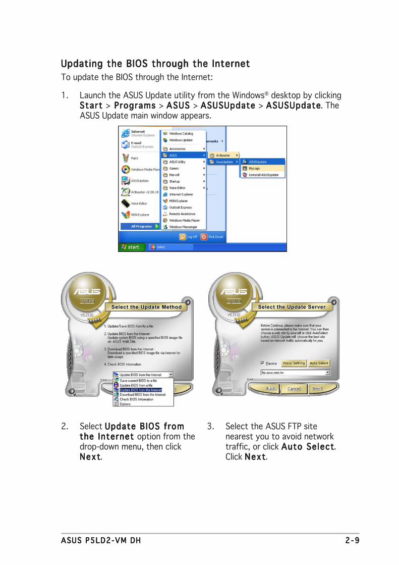
ASUS P5LD2-VM DHASUS P5LD2-VM DHASUS P5LD2-VM DHASUS P5LD2-VM DHASUS P5LD2-VM DH 2 - 92 - 92 - 92 - 92 - 9
3. Select the ASUS FTP sitenearest you to avoid networktraffic, or click Auto Se lectAuto Se lectAuto Se lectAuto Se lectAuto Se lect.Click NextNextNextNextNext.
Updating the BIOS through the InternetUpdating the BIOS through the InternetUpdating the BIOS through the InternetUpdating the BIOS through the InternetUpdating the BIOS through the InternetTo update the BIOS through the Internet:
1. Launch the ASUS Update utility from the Windows® desktop by clickingStart Start Start Start Start > Programs Programs Programs Programs Programs > ASUS ASUS ASUS ASUS ASUS > ASUSUpdate ASUSUpdate ASUSUpdate ASUSUpdate ASUSUpdate > ASUSUpdateASUSUpdateASUSUpdateASUSUpdateASUSUpdate. TheASUS Update main window appears.
2. Select Update B IOS fromUpdate B IOS fromUpdate B IOS fromUpdate B IOS fromUpdate B IOS fromthe Internet the Internet the Internet the Internet the Internet option from thedrop-down menu, then clickNextNextNextNextNext.

2 -102 -102 -102 -102 -10 Chapter 2 : B IOS setupChapter 2 : B IOS setupChapter 2 : B IOS setupChapter 2 : B IOS setupChapter 2 : B IOS setup
Updating the BIOS through a BIOS fi leUpdating the BIOS through a BIOS fi leUpdating the BIOS through a BIOS fi leUpdating the BIOS through a BIOS fi leUpdating the BIOS through a BIOS fi leTo update the BIOS through a BIOS file:
1. Launch the ASUS Update utility from the Windows® desktop byclicking Start Start Start Start Start > Programs Programs Programs Programs Programs > ASUS ASUS ASUS ASUS ASUS > ASUSUpdate ASUSUpdate ASUSUpdate ASUSUpdate ASUSUpdate >ASUSUpdateASUSUpdateASUSUpdateASUSUpdateASUSUpdate. The ASUS Update main window appears.
2. Select Update B IOS from aUpdate B IOS from aUpdate B IOS from aUpdate B IOS from aUpdate B IOS from af i l e f i l e f i l e f i l e f i l e option from the drop-downmenu, then click NextNextNextNextNext.
4. From the FTP site, select theBIOS version that you wish todownload. Click Next.
5. Follow the screen instructions tocomplete the update process.
The ASUS Update utility iscapable of updating itselfthrough the Internet. Alwaysupdate the utility to avail allits features.
3. Locate the BIOS file from theOpen Open Open Open Open window, then click SaveSaveSaveSaveSave.
4. Follow the screen instructions tocomplete the update process.

ASUS P5LD2-VM DHASUS P5LD2-VM DHASUS P5LD2-VM DHASUS P5LD2-VM DHASUS P5LD2-VM DH 2 -112 -112 -112 -112 -11
2.2 BIOS setup programThis motherboard supports a programmable firmware chip that you canupdate using the provided utility described in section “2.1 Managing andupdating your BIOS.”
Use the BIOS Setup program when you are installing a motherboard,reconfiguring your system, or prompted to “Run Setup”. This sectionexplains how to configure your system using this utility.
Even if you are not prompted to use the Setup program, you can changethe configuration of your computer in the future. For example, you canenable the security password feature or change the power managementsettings. This requires you to reconfigure your system using the BIOSSetup program so that the computer can recognize these changes andrecord them in the CMOS RAM of the firmware hub.
The firmware hub on the motherboard stores the Setup utility. When youstart up the computer, the system provides you with the opportunity torun this program. Press <Del> during the Power-On-Self-Test (POST) toenter the Setup utility; otherwise, POST continues with its test routines.
If you wish to enter Setup after POST, restart the system by pressing<Ctrl+Alt+Delete>, or by pressing the reset button on the system chassis.You can also restart by turning the system off and then back on. Do thislast option only if the first two failed.
The Setup program is designed to make it as easy to use as possible. Beinga menu-driven program, it lets you scroll through the various sub-menusand make your selections from the available options using the navigationkeys.
• The default BIOS settings for this motherboard apply for mostconditions to ensure optimum performance. If the system becomesunstable after changing any BIOS settings, load the default settingsto ensure system compatibility and stability. Select the L o a dL o a dL o a dL o a dL o a dDefau l t Sett ingsDefau l t Sett ingsDefau l t Sett ingsDefau l t Sett ingsDefau l t Sett ings item under the Exit Menu. See section “2.7 ExitMenu.”
• The BIOS setup screens shown in this section are for referencepurposes only, and may not exactly match what you see on yourscreen.
• Visit the ASUS website (www.asus.com) to download the latest BIOSfile for this motherboard and .

2 -122 -122 -122 -122 -12 Chapter 2 : B IOS setupChapter 2 : B IOS setupChapter 2 : B IOS setupChapter 2 : B IOS setupChapter 2 : B IOS setup
System Time [11:51:19]System Date [Thu 05/07/2004]Legacy Diskette A [1.44M, 3.5 in]
Primary IDE Master :[ST320413A]Primary IDE Slave :[Not Detected]Third IDE Master :[Not Detected]Third IDE Slave :[Not Detected]Fourth IDE Master :[Not Detected]Fourth IDE Slave :[Not Detected]IDE Configuration
System Information
Use [ENTER], [TAB]or [SHIFT-TAB] toselect a field.
Use [+] or [-] toconfigure system time.
2.2.22.2.22.2.22.2.22.2.2 Menu barMenu barMenu barMenu barMenu barThe menu bar on top of the screen has the following main items:
Ma inMa inMa inMa inMa in For changing the basic system configurationAdvancedAdvancedAdvancedAdvancedAdvanced For changing the advanced system settingsPowerPowerPowerPowerPower For changing the advanced power management (APM)
configurationBootBootBootBootBoot For changing the system boot configurationEx i tEx i tEx i tEx i tEx i t For selecting the exit options and loading default
settings
2.2.12.2.12.2.12.2.12.2.1 BIOS menu screenBIOS menu screenBIOS menu screenBIOS menu screenBIOS menu screen
To select an item on the menu bar, press the right or left arrow key on thekeyboard until the desired item is highlighted.
Some of the navigation keys differ from one screen to another.
Nav i ga t i on keysNav i ga t i on keysNav i ga t i on keysNav i ga t i on keysNav i ga t i on keys
Gene r a l he l pGene r a l he l pGene r a l he l pGene r a l he l pGene r a l he l pMenu ba rMenu ba rMenu ba rMenu ba rMenu ba r
Sub -menu i t emsSub -menu i t emsSub -menu i t emsSub -menu i t emsSub -menu i t ems
Con f i gu ra t i on f i e l d sCon f i gu ra t i on f i e l d sCon f i gu ra t i on f i e l d sCon f i gu ra t i on f i e l d sCon f i gu ra t i on f i e l d sMenu i t emsMenu i t emsMenu i t emsMenu i t emsMenu i t ems
2.2.32.2.32.2.32.2.32.2.3 Navigation keysNavigation keysNavigation keysNavigation keysNavigation keysAt the bottom right corner of a menu screen are the navigation keys forthat particular menu. Use the navigation keys to select items in the menuand change the settings.

ASUS P5LD2-VM DHASUS P5LD2-VM DHASUS P5LD2-VM DHASUS P5LD2-VM DHASUS P5LD2-VM DH 2 -132 -132 -132 -132 -13
2.2.42.2.42.2.42.2.42.2.4 Menu itemsMenu itemsMenu itemsMenu itemsMenu itemsThe highlighted item on the menu bardisplays the specific items for that menu.For example, selecting Ma in Ma in Ma in Ma in Ma in shows theMain menu items.
The other items (Advanced, Power, Boot,and Exit) on the menu bar have theirrespective menu items.
2.2.52.2.52.2.52.2.52.2.5 Sub-menu itemsSub-menu itemsSub-menu itemsSub-menu itemsSub-menu itemsA solid triangle before each item on any menu screen means that the iteamhas a sub-menu. To display the sub-menu, select the item and press<Enter>.
2.2.62.2.62.2.62.2.62.2.6 Configuration fieldsConfiguration fieldsConfiguration fieldsConfiguration fieldsConfiguration fieldsThese fields show the values for the menu items. If an item is user-configurable, you can change the value of the field opposite the item. Youcannot select an item that is not user-configurable.
A configurable field is enclosed in brackets, and is highlighted whenselected. To change the value of a field, select it then press <Enter> todisplay a list of options. Refer to “2.2.7 Pop-up window.”
2.2.72.2.72.2.72.2.72.2.7 Pop-up windowPop-up windowPop-up windowPop-up windowPop-up windowSelect a menu item then press <Enter> to display a pop-up window withthe configuration options for that item.
2.2.82.2.82.2.82.2.82.2.8 Scroll barScroll barScroll barScroll barScroll barA scroll bar appears on the right sideof a menu screen when there are itemsthat do not fit on the screen. Press theUp/Down arrow keys or <Page Up> /<Page Down> keys to display the otheritems on the screen.
2.2.92.2.92.2.92.2.92.2.9 General helpGeneral helpGeneral helpGeneral helpGeneral helpAt the top right corner of the menuscreen is a brief description of theselected item.
Sc ro l l b a rSc ro l l b a rSc ro l l b a rSc ro l l b a rSc ro l l b a r
Pop -up w i ndowPop -up w i ndowPop -up w i ndowPop -up w i ndowPop -up w i ndow
Ma in menu i t emsMa i n menu i t emsMa i n menu i t emsMa i n menu i t emsMa i n menu i t ems

2 -142 -142 -142 -142 -14 Chapter 2 : B IOS setupChapter 2 : B IOS setupChapter 2 : B IOS setupChapter 2 : B IOS setupChapter 2 : B IOS setup
2.3 Main menuWhen you enter the BIOS Setup program, the Main menu screen appears,giving you an overview of the basic system information.
2.3.12.3.12.3.12.3.12.3.1 System Time [xx:xx:xx]System Time [xx:xx:xx]System Time [xx:xx:xx]System Time [xx:xx:xx]System Time [xx:xx:xx]Allows you to set the system time.
2.3.22.3.22.3.22.3.22.3.2 System Date [Day xx/xx/xxxx]System Date [Day xx/xx/xxxx]System Date [Day xx/xx/xxxx]System Date [Day xx/xx/xxxx]System Date [Day xx/xx/xxxx]Allows you to set the system date.
2.3.32.3.32.3.32.3.32.3.3 Legacy Diskette A [1.44M, 3.5 in.]Legacy Diskette A [1.44M, 3.5 in.]Legacy Diskette A [1.44M, 3.5 in.]Legacy Diskette A [1.44M, 3.5 in.]Legacy Diskette A [1.44M, 3.5 in.]Sets the type of floppy drive installed. Configuration options: [Disabled][360K, 5.25 in.] [1.2M , 5.25 in.] [720K , 3.5 in.] [1.44M, 3.5 in.][2.88M, 3.5 in.]
Refer to section “2.2.1 BIOS menu screen” for information on the menuscreen items and how to navigate through them.
System Time [11:51:19]System Date [Thu 05/07/2004]Legacy Diskette A [1.44M, 3.5 in]
Primary IDE Master :[ST320413A]Primary IDE Slave :[Not Detected]Third IDE Master :[Not Detected]Third IDE Slave :[Not Detected]Fourth IDE Master :[Not Detected]Fourth IDE Slave :[Not Detected]IDE Configuration
System Information
Use [ENTER], [TAB]or [SHIFT-TAB] toselect a field.
Use [+] or [-] toconfigure system time.

ASUS P5LD2-VM DHASUS P5LD2-VM DHASUS P5LD2-VM DHASUS P5LD2-VM DHASUS P5LD2-VM DH 2 -152 -152 -152 -152 -15
2.3.42.3.42.3.42.3.42.3.4 Primary, Third and Fourth IDE Master/SlavePrimary, Third and Fourth IDE Master/SlavePrimary, Third and Fourth IDE Master/SlavePrimary, Third and Fourth IDE Master/SlavePrimary, Third and Fourth IDE Master/SlaveWhile entering Setup, the BIOS automatically detects the presence of IDEdevices. There is a separate sub-menu for each IDE device. Select a deviceitem then press <Enter> to display the IDE device information.
The BIOS automatically detects the values opposite the dimmed items(Device, Vendor, Size, LBA Mode, Block Mode, PIO Mode, Async DMA, UltraDMA, and SMART monitoring). These values are not user-configurable.These items show N/A if no IDE device is installed in the system.
Type [Auto]Type [Auto]Type [Auto]Type [Auto]Type [Auto]Selects the type of IDE drive. Setting to Auto allows automatic selection ofthe appropriate IDE device type. Select CDROM if you are specificallyconfiguring a CD-ROM drive. Select ARMD (ATAPI Removable Media Device)if your device is either a ZIP, LS-120, or MO drive. Configuration options:[Not Installed] [Auto] [CDROM] [ARMD]
LBA/Large Mode [Auto]LBA/Large Mode [Auto]LBA/Large Mode [Auto]LBA/Large Mode [Auto]LBA/Large Mode [Auto]Enables or disables the LBA mode. Setting to Auto enables the LBA mode ifthe device supports this mode, and if the device was not previouslyformatted with LBA mode disabled. Configuration options: [Disabled][Auto]
Block (Multi-sector Transfer) [Auto]Block (Multi-sector Transfer) [Auto]Block (Multi-sector Transfer) [Auto]Block (Multi-sector Transfer) [Auto]Block (Multi-sector Transfer) [Auto]Enables or disables data multi-sectors transfers. When set to Auto, thedata transfer from and to the device occurs multiple sectors at a time ifthe device supports multi-sector transfer feature. When set to [Disabled],the data transfer from and to the device occurs one sector at a time.Configuration options: [Disabled] [Auto]
Primary IDE Master
Device : Hard DiskVendor : ST320413ASize : 20.0GBLBA Mode : SupportedBlock Mode : 16 SectorsPIO Mode : SupportedAsync DMA : MultiWord DMA-2Ultra DMA : Ultra DMA-5SMART Monitoring: Supported
Type [Auto]LBA/Large Mode [Auto]Block(Multi-sector Transfer) [Auto]PIO Mode [Auto]DMA Mode [Auto]Smart Monitoring [Auto]32Bit Data Transfer [Disabled]

2 -162 -162 -162 -162 -16 Chapter 2 : B IOS setupChapter 2 : B IOS setupChapter 2 : B IOS setupChapter 2 : B IOS setupChapter 2 : B IOS setup
PIO Mode [Auto]PIO Mode [Auto]PIO Mode [Auto]PIO Mode [Auto]PIO Mode [Auto]Selects the PIO mode.Configuration options: [Auto] [0] [1] [2] [3] [4]
DMA Mode [Auto]DMA Mode [Auto]DMA Mode [Auto]DMA Mode [Auto]DMA Mode [Auto]Selects the DMA mode. Configuration options: [Auto] [SWDMA0][SWDMA1] [SWDMA2] [MWDMA0] [MWDMA1] [MWDMA2] [UDMA0][UDMA1] [UDMA2] [UDMA3] [UDMA4] [UDMA5]
SMART Monitoring [Auto]SMART Monitoring [Auto]SMART Monitoring [Auto]SMART Monitoring [Auto]SMART Monitoring [Auto]Sets the Smart Monitoring, Analysis, and Reporting Technology.Configuration options: [Auto] [Disabled] [Enabled]
32Bit Data Transfer [Disabled]32Bit Data Transfer [Disabled]32Bit Data Transfer [Disabled]32Bit Data Transfer [Disabled]32Bit Data Transfer [Disabled]Enables or disables 32-bit data transfer.Configuration options: [Disabled] [Enabled]
2.3.52.3.52.3.52.3.52.3.5 IDE ConfigurationIDE ConfigurationIDE ConfigurationIDE ConfigurationIDE ConfigurationThe items in this menu allow you to set or change the configurations forthe IDE devices installed in the system. Select an item then press <Enter>if you wish to configure the item.
IDE Configuration
Configure SATA As [Standard IDE]Onboard IDE Operate Mode [Enhanced Mode]
Enhanced Mode Support On [S-ATA]OnBoard Serial-ATA BOOT ROM [Disabled]
IDE Detect Time Out (Sec) [35]
Configure SATA As [Standard IDE]Configure SATA As [Standard IDE]Configure SATA As [Standard IDE]Configure SATA As [Standard IDE]Configure SATA As [Standard IDE]Sets the Serial ATA configuration.
If you want to use your Serial ATA like a Parallel ATA physical storageinterface, select the Standard IDE option.
Configuration options: [Standard IDE]
Onboard IDE Operate Mode [Enhanced Mode]Onboard IDE Operate Mode [Enhanced Mode]Onboard IDE Operate Mode [Enhanced Mode]Onboard IDE Operate Mode [Enhanced Mode]Onboard IDE Operate Mode [Enhanced Mode]Disables or allows selection of the IDE operation mode depending on theoperating system (OS) that you installed. Set to Enhanced Mode if you areusing native OS, such as Windows® 2000/XP/2003 Server.Configuration options: [Disabled] [Compatible Mode] [Enhanced Mode]
ASUS P5LD2-VM DHASUS P5LD2-VM DHASUS P5LD2-VM DHASUS P5LD2-VM DHASUS P5LD2-VM DH 2 -172 -172 -172 -172 -17
Enhanced Mode Support On [S-ATA]The default setting S-ATA allows you to use native OS on Serial ATAand Parallel ATA ports. We recommend that you do not change thedefault setting for better OS compatibility. In this setting, you mayuse legacy OS on the Parallel ATA ports on ly i fon ly i fon ly i fon ly i fon ly i f you did not install anySerial ATA device.
The P-ATA+S-ATA and P-ATA options are for advanced users only. Ifyou set to any of these options and encounter problems, revert to thedefault setting S -ATAS-ATAS-ATAS-ATAS-ATA. Configuration options: [P-ATA+S-ATA][S-ATA] [P-ATA]
Onboard SATA Boot Rom [Disabled]Allows you to enable or disable the onboard Serial ATA Boot ROM. Setthis item to [Enabled] to configure Serial ATA RAID.Configuration option: [Disabled] [Enabled]
IDE Detect Time Out [35]IDE Detect Time Out [35]IDE Detect Time Out [35]IDE Detect Time Out [35]IDE Detect Time Out [35]Selects the time out value for detecting ATA/ATAPI devices.Configuration options: [0] [5] [10] [15] [20] [25] [30] [35]

2 -182 -182 -182 -182 -18 Chapter 2 : B IOS setupChapter 2 : B IOS setupChapter 2 : B IOS setupChapter 2 : B IOS setupChapter 2 : B IOS setup
2.3.62.3.62.3.62.3.62.3.6 System InformationSystem InformationSystem InformationSystem InformationSystem InformationThis menu gives you an overview of the general system specifications. TheBIOS automatically detects the items in this menu.
AMI BIOSAMI BIOSAMI BIOSAMI BIOSAMI BIOSDisplays the auto-detected BIOS information
ProcessorProcessorProcessorProcessorProcessorDisplays the auto-detected CPU specification
System MemorySystem MemorySystem MemorySystem MemorySystem MemoryDisplays the auto-detected system memory
AMIBIOSVersion : 0128Build Date : 05/11/05
ProcessorType : Genuine Intel(R) CPU 3.20GHzSpeed : 3200 MHzCount : 1
System MemorySize : 512MBAppropriated : 0MBAvailable : 504MB

ASUS P5LD2-VM DHASUS P5LD2-VM DHASUS P5LD2-VM DHASUS P5LD2-VM DHASUS P5LD2-VM DH 2 -192 -192 -192 -192 -19
2.4 Advanced menuThe Advanced menu items allow you to change the settings for the CPUand other system devices.
Take caution when changing the settings of the Advanced menu items.Incorrect field values can cause the system to malfunction.
JumperFree ConfigurationUSB Configuration
CPU ConfigurationChipsetOnboard Devices ConfigurationPCI PnP
2.4.12.4.12.4.12.4.12.4.1 JumperFree ConfigurationJumperFree ConfigurationJumperFree ConfigurationJumperFree ConfigurationJumperFree Configuration
AI Overclocking [Auto]AI Overclocking [Auto]AI Overclocking [Auto]AI Overclocking [Auto]AI Overclocking [Auto]Allows selection of CPU overclocking options to achieve desired CPUinternal frequency. Select either one of the preset overclockingconfiguration options:
Manua l Manua l Manua l Manua l Manua l - allows you to individually set overclocking parameters.Auto Auto Auto Auto Auto - loads the optimal settings for the system.Standard Standard Standard Standard Standard - loads the standard settings for the system.Overc lock Prof i le Overc lock Prof i le Overc lock Prof i le Overc lock Prof i le Overc lock Prof i le - loads overclocking profiles with optimal parameters
for stability when overclocking.
Configure System Frequency/Voltage
AI Overclocking [Auto]
Select the target CPUfrequency, and therelevant parameterswill be auto-adjusted.Frequencies higherthan CPU manufacturerrecommends are notguaranteed to bestable. If the system

2 -202 -202 -202 -202 -20 Chapter 2 : B IOS setupChapter 2 : B IOS setupChapter 2 : B IOS setupChapter 2 : B IOS setupChapter 2 : B IOS setup
FSB/CPU External Frequency Synchronizat ionFSB/CPU External Frequency Synchronizat ionFSB/CPU External Frequency Synchronizat ionFSB/CPU External Frequency Synchronizat ionFSB/CPU External Frequency Synchronizat ion
F ron t S i de BusF ron t S i de BusF ron t S i de BusF ron t S i de BusF ron t S i de Bus CPU Ex te rna l F r equencyCPU Ex te rna l F r equencyCPU Ex te rna l F r equencyCPU Ex te rna l F r equencyCPU Ex te rna l F r equencyFSB 1066 266 MHzFSB 800 200 MHzFSB 533 133 MHz
DRAM Frequency [Auto]DRAM Frequency [Auto]DRAM Frequency [Auto]DRAM Frequency [Auto]DRAM Frequency [Auto]Allows you to set the DDR2 operating frequency.Configuration options: [Auto] [DDR2-400MHz] [DDR2-533MHz][DDR-667MHz]
Selecting a very high DRAM frequency may cause the system to becomeunstable! If this happens, revert to the default setting.
The following item appears only when you set the A I Overc lock ingA I Overc lock ingA I Overc lock ingA I Overc lock ingA I Overc lock ingitem to [Manual].
CPU Frequency [XXX]CPU Frequency [XXX]CPU Frequency [XXX]CPU Frequency [XXX]CPU Frequency [XXX]Displays the frequency sent by the clock generator to the system bus andPCI bus. The value of this item is auto-detected by the BIOS. Use the <+><+><+><+><+>and < ->< ->< ->< ->< -> keys to adjust the CPU frequency. You can also type the desiredCPU frequency using the numeric keypad. The values range from 100 to400. Refer to the table below for the correct Front Side Bus and CPUExternal Frequency settings.
PCI Express Frequency [Auto]PCI Express Frequency [Auto]PCI Express Frequency [Auto]PCI Express Frequency [Auto]PCI Express Frequency [Auto]Allows you to set the PCI Express frequency. This item is set to [Auto] bydefault. Configuration options: [Auto] [90]...[150]
PCI Clock Synchronization Mode [To PCI Express]PCI Clock Synchronization Mode [To PCI Express]PCI Clock Synchronization Mode [To PCI Express]PCI Clock Synchronization Mode [To PCI Express]PCI Clock Synchronization Mode [To PCI Express]Allows you to synchronize the PCI frequency with the PCI Express or CPUfrequency. Configuration options: [To PCI Express] [Fixed 33.3MHz][Fixed 36.3MHz] [Fixed 40.0MHz]
Memory Voltage [Auto]Memory Voltage [Auto]Memory Voltage [Auto]Memory Voltage [Auto]Memory Voltage [Auto]Allows you to select the DDR2 reference voltage.Configuration options: [Auto] [1.812V] [1.904V]
Refer to the DDR2 documentation before adjusting the memory voltage.Setting a very high memory voltage may damage the memory module(s)!

ASUS P5LD2-VM DHASUS P5LD2-VM DHASUS P5LD2-VM DHASUS P5LD2-VM DHASUS P5LD2-VM DH 2 -212 -212 -212 -212 -21
• Setting to a very high CPU VCore voltage can damage the CPU ormay cause the system to become unstable. If this happens, revertto default settings.
• The following item appears only when the A I Overc lock ing A I Overc lock ing A I Overc lock ing A I Overc lock ing A I Overc lock ing itemis set to [Overclock Profile].
MCH Chipset Voltage [Auto]MCH Chipset Voltage [Auto]MCH Chipset Voltage [Auto]MCH Chipset Voltage [Auto]MCH Chipset Voltage [Auto]Allows you to select the memory controller hub (MCH) voltage.Configuration options: [Auto] [1.50V] [1.60V] [1.70V]
CPU VCore Voltage [Auto]CPU VCore Voltage [Auto]CPU VCore Voltage [Auto]CPU VCore Voltage [Auto]CPU VCore Voltage [Auto]Sets the operating VCore voltage. Configuration options: [Auto][1.7000V] [1.6875V] [1.6750V] [1.6625V] [1.6500V] [1.6375V][1.6250V] [1.6125V] [1.6000V] [1.5875V] [1.5750V] [1.5625V][1.5500V] [1.5375V] [1.5250V] [1.5125V] [1.5000V] [1.4875V][1.4750V] [1.4625V] [1.4500V] [1.4375V] [1.4250V] [1.4125V][1.4000V] [1.3875V] [1.3750V] [1.3625V] [1.3500V] [1.3375V][1.3250V] [1.3125V] [1.3000V] [1.2875V]
Overclock Options [Overclock 5%]Overclock Options [Overclock 5%]Overclock Options [Overclock 5%]Overclock Options [Overclock 5%]Overclock Options [Overclock 5%]Allows you to overclock the CPU speed through the available preset values.Configuration options: [Overclock 5%] [Overclock 10%] [Overclock 15%][Overclock 20%] [Overclock 30%]

2 -222 -222 -222 -222 -22 Chapter 2 : B IOS setupChapter 2 : B IOS setupChapter 2 : B IOS setupChapter 2 : B IOS setupChapter 2 : B IOS setup
USB Function [Enabled]USB Function [Enabled]USB Function [Enabled]USB Function [Enabled]USB Function [Enabled]Allows you to enable or disable the USB function.Configuration options: [Disabled] [Enabled]
Legacy USB Support [Auto]Legacy USB Support [Auto]Legacy USB Support [Auto]Legacy USB Support [Auto]Legacy USB Support [Auto]Allows you to enable or disable support for USB devices on legacyoperating systems (OS). Setting to Auto allows the system to detect thepresence of USB devices at startup. If detected, the USB controller legacymode is enabled. If no USB device is detected, the legacy USB support isdisabled. Configuration options: [Disabled] [Enabled] [Auto]
USB 2.0 Controller [Enabled]USB 2.0 Controller [Enabled]USB 2.0 Controller [Enabled]USB 2.0 Controller [Enabled]USB 2.0 Controller [Enabled]Allows you to enable or disable the USB 2.0 controller.Configuration options: [Disabled] [Enabled]
USB 2.0 Controller Mode [HiSpeed]USB 2.0 Controller Mode [HiSpeed]USB 2.0 Controller Mode [HiSpeed]USB 2.0 Controller Mode [HiSpeed]USB 2.0 Controller Mode [HiSpeed]Allows you to configure the USB 2.0 controller in HiSpeed (480 Mbps) orFull Speed (12 Mbps). Configuration options: [HiSpeed] [Full Speed]
BIOS EHCI Hand-off [Disabled]BIOS EHCI Hand-off [Disabled]BIOS EHCI Hand-off [Disabled]BIOS EHCI Hand-off [Disabled]BIOS EHCI Hand-off [Disabled]Allows you to enable support for operating systems without an EHCIhand-off feature. Configuration options: [Enabled] [Disabled]
The Module Version and USB Devices Enabled items show theauto-detected values. If no USB device is detected, the item showsNone.
2.4.22.4.22.4.22.4.22.4.2 USB ConfigurationUSB ConfigurationUSB ConfigurationUSB ConfigurationUSB ConfigurationThe items in this menu allows you to change the USB-related features.Select an item then press <Enter> to display the configuration options.
USB Configuration
Module Version - 2.23.0-F.4
USB Devices Enabled: None
USB Function [Enabled]Legacy USB Support [Auto]USB 2.0 Controller [Enabled]USB 2.0 Controller Mode [HiSpeed]BIOS EHCI Hand-Off [Disabled]
Do not disable the BIOS EHCI Hand-Off option if you are running aWindows® operating system with USB device.
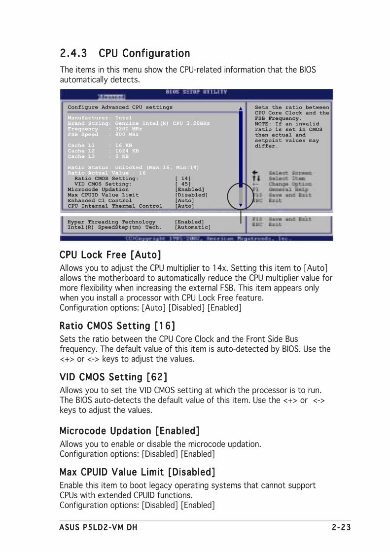
ASUS P5LD2-VM DHASUS P5LD2-VM DHASUS P5LD2-VM DHASUS P5LD2-VM DHASUS P5LD2-VM DH 2 -232 -232 -232 -232 -23
2.4.32.4.32.4.32.4.32.4.3 CPU ConfigurationCPU ConfigurationCPU ConfigurationCPU ConfigurationCPU ConfigurationThe items in this menu show the CPU-related information that the BIOSautomatically detects.
Configure Advanced CPU settings
Manufacturer: IntelBrand String: Genuine Intel(R) CPU 3.20GHzFrequency : 3200 MHzFSB Speed : 800 MHz
Cache L1 : 16 KBCache L2 : 1024 KBCache L3 : 0 KB
Ratio Status: Unlocked (Max:16, Min:14)Ratio Actual Value : 16 Ratio CMOS Setting: [ 14] VID CMOS Setting: [ 45]Microcode Updation [Enabled]Max CPUID Value Limit [Disabled]Enhanced C1 Control [Auto]CPU Internal Thermal Control [Auto]
Sets the ratio betweenCPU Core Clock and theFSB Frequency.NOTE: If an invalidratio is set in CMOSthen actual andsetpoint values maydiffer.
Hyper Threading Technology [Enabled]Intel(R) SpeedStep(tm) Tech. [Automatic]
CPU Lock Free [Auto]CPU Lock Free [Auto]CPU Lock Free [Auto]CPU Lock Free [Auto]CPU Lock Free [Auto]Allows you to adjust the CPU multiplier to 14x. Setting this item to [Auto]allows the motherboard to automatically reduce the CPU multiplier value formore flexibility when increasing the external FSB. This item appears onlywhen you install a processor with CPU Lock Free feature.Configuration options: [Auto] [Disabled] [Enabled]
Ratio CMOS Setting [16]Ratio CMOS Setting [16]Ratio CMOS Setting [16]Ratio CMOS Setting [16]Ratio CMOS Setting [16]Sets the ratio between the CPU Core Clock and the Front Side Busfrequency. The default value of this item is auto-detected by BIOS. Use the<+> or <-> keys to adjust the values.
VID CMOS Setting [62]VID CMOS Setting [62]VID CMOS Setting [62]VID CMOS Setting [62]VID CMOS Setting [62]Allows you to set the VID CMOS setting at which the processor is to run.The BIOS auto-detects the default value of this item. Use the <+> or <->keys to adjust the values.
Microcode Updation [Enabled]Microcode Updation [Enabled]Microcode Updation [Enabled]Microcode Updation [Enabled]Microcode Updation [Enabled]Allows you to enable or disable the microcode updation.Configuration options: [Disabled] [Enabled]
Max CPUID Value Limit [Disabled]Max CPUID Value Limit [Disabled]Max CPUID Value Limit [Disabled]Max CPUID Value Limit [Disabled]Max CPUID Value Limit [Disabled]Enable this item to boot legacy operating systems that cannot supportCPUs with extended CPUID functions.Configuration options: [Disabled] [Enabled]
2 -242 -242 -242 -242 -24 Chapter 2 : B IOS setupChapter 2 : B IOS setupChapter 2 : B IOS setupChapter 2 : B IOS setupChapter 2 : B IOS setup
CPU Internal Thermal Control [Auto]CPU Internal Thermal Control [Auto]CPU Internal Thermal Control [Auto]CPU Internal Thermal Control [Auto]CPU Internal Thermal Control [Auto]Disables or sets the CPU internal thermal control.Configuration options: [Disabled] [Auto]
Hyper-Threading Technology [Enabled]Hyper-Threading Technology [Enabled]Hyper-Threading Technology [Enabled]Hyper-Threading Technology [Enabled]Hyper-Threading Technology [Enabled]Allows you to enable or disable the processor Hyper-Threading Technology.Configuration options: [Disabled] [Enabled]
The following item appears only when you installed an Intel® Pentium® Dor Intel® Pentium® 4 CPU that supports the Enhanced Intel SpeedStep®
Technology (EIST).
Intel(R) SpeedStep Technology [Automatic]Intel(R) SpeedStep Technology [Automatic]Intel(R) SpeedStep Technology [Automatic]Intel(R) SpeedStep Technology [Automatic]Intel(R) SpeedStep Technology [Automatic]Allows you to use the Enhanced Intel SpeedStep® Technology. When set to[Automatic], you can adjust the system power settings in the operatingsystem to use the EIST feature.
Set this item to [Maximum] or [Disabled] if you do not want to use the EIST.The CPU constantly operates at a lower internal frequency when you setthis item to [Minimum].
Configuration options: [Maximum] [Minimum] [Automatic] [Disabled]
• Refer to the Appendix for details on how to use the EIST feature.• The motherboard comes with a BIOS file that supports EIST.

ASUS P5LD2-VM DHASUS P5LD2-VM DHASUS P5LD2-VM DHASUS P5LD2-VM DHASUS P5LD2-VM DH 2 -252 -252 -252 -252 -25
2.4.42.4.42.4.42.4.42.4.4 ChipsetChipsetChipsetChipsetChipsetThe Chipset menu allows you to change the advanced chipset settings.Select an item then press <Enter> to display the sub-menu.
Advanced Chipset Settings
Configure DRAM Timing by SPD [Enabled]
Booting Graphic Adapter Priori [PCI Express/Int-VG]Internal Graphics Mode Select [Enabled, 8MB]
Graphics memory type [Auto]
Advanced Chipset SettingsAdvanced Chipset SettingsAdvanced Chipset SettingsAdvanced Chipset SettingsAdvanced Chipset Settings
Configure DRAM Timing by SPD [Enabled]Configure DRAM Timing by SPD [Enabled]Configure DRAM Timing by SPD [Enabled]Configure DRAM Timing by SPD [Enabled]Configure DRAM Timing by SPD [Enabled]When this item is enabled, the DRAM timing parameters are set accordingto the DRAM SPD (Serial Presence Detect). When disabled, you canmanually set the DRAM timing parameters through the DRAM sub-items.The following sub-items appear when this item is Disabled.Configuration options: [Disabled] [Enabled]
DRAM CAS# Latency [5 Clocks]Controls the latency between the SDRAM read command and the timethe data actually becomes available.Configuration options: [6 Clocks] [5 Clocks] [4 Clocks] [3 Clocks]
DRAM RAS# Precharge [4 Clocks]Controls the idle clocks after issuing a precharge command to the DDRSDRAM. Configuration options: [2 Clocks] [3 Clocks] [4 Clocks][5 Clocks] [6 Clocks]
DRAM RAS# to CAS# Delay [4 Clocks]Controls the latency between the DDR SDRAM active command andthe read/write command. Configuration options: [2 Clocks] [3 Clocks][4 Clocks] [5 Clocks] [6 Clocks]
DRAM RAS# Activate to Precharge [15 Clocks]Sets the RAS Activate timing to Precharge timing.Configuration options: [4 Clocks] ~ [18 Clocks]
DRAM Write Recovery Time [4 Clocks]Sets the DRAM Write Recover Time.Configuration options: [2 Clocks] [3 Clocks] [4 Clocks] [5 Clocks][6 Clocks]
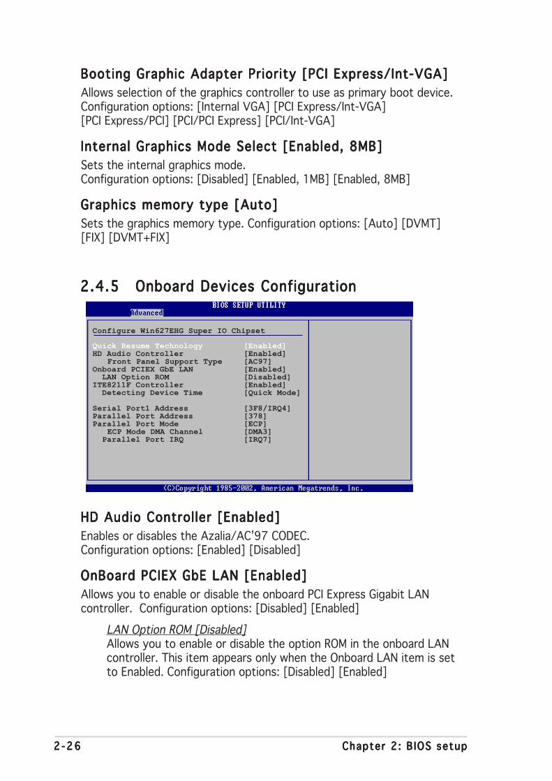
2 -262 -262 -262 -262 -26 Chapter 2 : B IOS setupChapter 2 : B IOS setupChapter 2 : B IOS setupChapter 2 : B IOS setupChapter 2 : B IOS setup
2.4.52.4.52.4.52.4.52.4.5 Onboard Devices ConfigurationOnboard Devices ConfigurationOnboard Devices ConfigurationOnboard Devices ConfigurationOnboard Devices Configuration
Configure Win627EHG Super IO Chipset
Quick Resume Technology [Enabled]HD Audio Controller [Enabled]
Front Panel Support Type [AC97]Onboard PCIEX GbE LAN [Enabled] LAN Option ROM [Disabled]ITE8211F Controller [Enabled] Detecting Device Time [Quick Mode]
Serial Port1 Address [3F8/IRQ4]Parallel Port Address [378]Parallel Port Mode [ECP]
ECP Mode DMA Channel [DMA3] Parallel Port IRQ [IRQ7]
Booting Graphic Adapter Priority [PCI Express/Int-VGA]Booting Graphic Adapter Priority [PCI Express/Int-VGA]Booting Graphic Adapter Priority [PCI Express/Int-VGA]Booting Graphic Adapter Priority [PCI Express/Int-VGA]Booting Graphic Adapter Priority [PCI Express/Int-VGA]Allows selection of the graphics controller to use as primary boot device.Configuration options: [Internal VGA] [PCI Express/Int-VGA][PCI Express/PCI] [PCI/PCI Express] [PCI/Int-VGA]
Internal Graphics Mode Select [Enabled, 8MB]Internal Graphics Mode Select [Enabled, 8MB]Internal Graphics Mode Select [Enabled, 8MB]Internal Graphics Mode Select [Enabled, 8MB]Internal Graphics Mode Select [Enabled, 8MB]Sets the internal graphics mode.Configuration options: [Disabled] [Enabled, 1MB] [Enabled, 8MB]
Graphics memory type [Auto]Graphics memory type [Auto]Graphics memory type [Auto]Graphics memory type [Auto]Graphics memory type [Auto]Sets the graphics memory type. Configuration options: [Auto] [DVMT][FIX] [DVMT+FIX]
HD Audio Controller [Enabled]HD Audio Controller [Enabled]HD Audio Controller [Enabled]HD Audio Controller [Enabled]HD Audio Controller [Enabled]Enables or disables the Azalia/AC’97 CODEC.Configuration options: [Enabled] [Disabled]
OnBoard PCIEX GbE LAN [Enabled]OnBoard PCIEX GbE LAN [Enabled]OnBoard PCIEX GbE LAN [Enabled]OnBoard PCIEX GbE LAN [Enabled]OnBoard PCIEX GbE LAN [Enabled]Allows you to enable or disable the onboard PCI Express Gigabit LANcontroller. Configuration options: [Disabled] [Enabled]
LAN Option ROM [Disabled]Allows you to enable or disable the option ROM in the onboard LANcontroller. This item appears only when the Onboard LAN item is setto Enabled. Configuration options: [Disabled] [Enabled]

ASUS P5LD2-VM DHASUS P5LD2-VM DHASUS P5LD2-VM DHASUS P5LD2-VM DHASUS P5LD2-VM DH 2 -272 -272 -272 -272 -27
ITE8211F Controller [Enabled]ITE8211F Controller [Enabled]ITE8211F Controller [Enabled]ITE8211F Controller [Enabled]ITE8211F Controller [Enabled]Enables or disables the onboard ITE® 8211F IDE controller.Configuration options: [Enabled] [Disabled]
Detecting Device Time [Quick Mode]Sets the ITE8211F detecting device time. If the devices installed onthe ITE IDE connector cannot be detected, set this item to StandardMode to enable complete detecting process. This item appears onlywhen the ITE8211F Controller is Enabled.Configuration options: [Standard Mode] [Quick Mode]
Serial Port1 Address [3F8/IRQ4]Serial Port1 Address [3F8/IRQ4]Serial Port1 Address [3F8/IRQ4]Serial Port1 Address [3F8/IRQ4]Serial Port1 Address [3F8/IRQ4]Allows you to select the Serial Port1 base address.Configuration options: [Disabled] [3F8/IRQ4] [2F8/IRQ3] [3E8/IRQ4][2E8/IRQ3]
Parallel Port Address [378]Parallel Port Address [378]Parallel Port Address [378]Parallel Port Address [378]Parallel Port Address [378]Allows you to select the Parallel Port base addresses.Configuration options: [Disabled] [378] [278] [3BC]
Parallel Port Mode [ECP]Parallel Port Mode [ECP]Parallel Port Mode [ECP]Parallel Port Mode [ECP]Parallel Port Mode [ECP]Allows you to select the Parallel Port mode.Configuration options: [Normal] [Bi-directional] [EPP] [ECP]
ECP Mode DMA Channe l [DMA3]ECP Mode DMA Channe l [DMA3]ECP Mode DMA Channe l [DMA3]ECP Mode DMA Channe l [DMA3]ECP Mode DMA Channe l [DMA3]
Appears only when the Parallel Port Mode is set to [ECP]. This itemallows you to set the Parallel Port ECP DMA.Configuration options: [DMA0] [DMA1] [DMA3]
EPP Ve r s i on [1 .9 ]EPP Ve r s i on [1 .9 ]EPP Ve r s i on [1 .9 ]EPP Ve r s i on [1 .9 ]EPP Ve r s i on [1 .9 ]
Allows selection of the Parallel Port EPP version. This item appearsonly when the Para l le l Port ModePara l le l Port ModePara l le l Port ModePara l le l Port ModePara l le l Port Mode is set to E PPEPPEPPEPPEPP.Configuration options: [1.9] [1.7]
Parallel Port IRQ [IRQ7]Configuration options: [IRQ5] [IRQ7]

2 -282 -282 -282 -282 -28 Chapter 2 : B IOS setupChapter 2 : B IOS setupChapter 2 : B IOS setupChapter 2 : B IOS setupChapter 2 : B IOS setup
2.4.62.4.62.4.62.4.62.4.6 PCI PnPPCI PnPPCI PnPPCI PnPPCI PnPThe PCI PnP menu items allow you to change the advanced settings forPCI/PnP devices. The menu includes setting IRQ and DMA channel resourcesfor either PCI/PnP or legacy ISA devices, and setting the memory size blockfor legacy ISA devices.
Take caution when changing the settings of the PCI PnP menu items.Incorrect field values can cause the system to malfunction.
Advanced PCI/PnP Settings
WARNING: Setting wrong values in below sections may cause system to malfunction.
Plug And Play O/S [No]PCI Latency Timer [64]Allocate IRQ to PCI VGA [Yes]Palette Snooping [Disabled]
IRQ-3 assigned to [PCI Device]IRQ-4 assigned to [PCI Device]IRQ-5 assigned to [PCI Device]IRQ-7 assigned to [PCI Device]IRQ-9 assigned to [PCI Device]IRQ-10 assigned to [PCI Device]IRQ-11 assigned to [PCI Device]IRQ-14 assigned to [PCI Device]IRQ-15 assigned to [PCI Device]
Plug and Play O/S [No]Plug and Play O/S [No]Plug and Play O/S [No]Plug and Play O/S [No]Plug and Play O/S [No]When set to [No], BIOS configures all the devices in the system. When setto [Yes] and if you install a Plug and Play operating system, the operatingsystem configures the Plug and Play devices not required for boot.Configuration options: [No] [Yes]
PCI Latency Timer [64]PCI Latency Timer [64]PCI Latency Timer [64]PCI Latency Timer [64]PCI Latency Timer [64]Allows you to select the value in units of PCI clocks for the PCI devicelatency timer register. Configuration options: [32] [64] [96] [128] [160][192] [224] [248]
Allocate IRQ to PCI VGA [Yes]Allocate IRQ to PCI VGA [Yes]Allocate IRQ to PCI VGA [Yes]Allocate IRQ to PCI VGA [Yes]Allocate IRQ to PCI VGA [Yes]When set to [Yes], BIOS assigns an IRQ to PCI VGA card if the cardrequests for an IRQ. When set to [No], BIOS does not assign an IRQ to thePCI VGA card even if requested. Configuration options: [No] [Yes]
Palette Snooping [Disabled]Palette Snooping [Disabled]Palette Snooping [Disabled]Palette Snooping [Disabled]Palette Snooping [Disabled]When set to [Enabled], the pallete snooping feature informs the PCIdevices that an ISA graphics device is installed in the system so that thelatter can function correctly. Configuration options: [Disabled] [Enabled]

ASUS P5LD2-VM DHASUS P5LD2-VM DHASUS P5LD2-VM DHASUS P5LD2-VM DHASUS P5LD2-VM DH 2 -292 -292 -292 -292 -29
IRQ-xx assigned to [PCI Device]IRQ-xx assigned to [PCI Device]IRQ-xx assigned to [PCI Device]IRQ-xx assigned to [PCI Device]IRQ-xx assigned to [PCI Device]When set to [PCI Device], the specific IRQ is free for use of PCI/PnPdevices. When set to [Reserved], the IRQ is reserved for legacy ISAdevices. Configuration options: [PCI Device] [Reserved]
2.5 Power menuThe Power menu items allow you to change the settings for the AdvancedConfiguration and Power Interface (ACPI) and the Advanced PowerManagement (APM). Select an item then press <Enter> to display theconfiguration options.
2.5.12.5.12.5.12.5.12.5.1 Suspend Mode [Auto]Suspend Mode [Auto]Suspend Mode [Auto]Suspend Mode [Auto]Suspend Mode [Auto]Allows you to select the Advanced Configuration and Power Interface(ACPI) state to be used for system suspend.Configuration options: [S1 (POS) Only] [S3 Only] [Auto]
2.5.22.5.22.5.22.5.22.5.2 Repost Video on S3 Resume [No]Repost Video on S3 Resume [No]Repost Video on S3 Resume [No]Repost Video on S3 Resume [No]Repost Video on S3 Resume [No]Determines whether to invoke VGA BIOS POST on S3/STR resume.Configuration options: [No] [Yes]
2.5.32.5.32.5.32.5.32.5.3 ACPI 2.0 Support [No]ACPI 2.0 Support [No]ACPI 2.0 Support [No]ACPI 2.0 Support [No]ACPI 2.0 Support [No]Allows you to add more tables for Advanced Configuration and PowerInterface (ACPI) 2.0 specifications. Configuration options: [No] [Yes]
2.5.42.5.42.5.42.5.42.5.4 ACPI APIC Support [Enabled]ACPI APIC Support [Enabled]ACPI APIC Support [Enabled]ACPI APIC Support [Enabled]ACPI APIC Support [Enabled]Allows you to enable or disable the Advanced Configuration and PowerInterface (ACPI) support in the Application-Specific Integrated Circuit(ASIC). When set to Enabled, the ACPI APIC table pointer is included in theRSDT pointer list. Configuration options: [Disabled] [Enabled]
Suspend Mode [Auto]Repost Video on S3 Resume [No]ACPI 2.0 Support [No]ACPI APIC Support [Enabled] APM Configuration Hardware MonitorQuick Resume

2 -302 -302 -302 -302 -30 Chapter 2 : B IOS setupChapter 2 : B IOS setupChapter 2 : B IOS setupChapter 2 : B IOS setupChapter 2 : B IOS setup
2.5.52.5.52.5.52.5.52.5.5 APM ConfigurationAPM ConfigurationAPM ConfigurationAPM ConfigurationAPM Configuration
APM Configuration
Power Button Mode [On/Off]
Restore on AC Power Loss [Power Off]Power On By RTC Alarm [Disabled]Power On By External Modems [Disabled]Power On By PCI Devices [Disabled]Power On By PCIE Devices [Disabled]
Power Button Mode [On/Off]Power Button Mode [On/Off]Power Button Mode [On/Off]Power Button Mode [On/Off]Power Button Mode [On/Off]Allows the system to go into On/Off mode or suspend mode when thepower button is pressed. Configuration options: [On/Off] [Suspend]
Restore on AC Power Loss [Power Off]Restore on AC Power Loss [Power Off]Restore on AC Power Loss [Power Off]Restore on AC Power Loss [Power Off]Restore on AC Power Loss [Power Off]When set to Power Off, the system goes into off state after an AC powerloss. When set to Power On, the system goes on after an AC power loss.When set to Last State, the system goes into either off or on state,whatever the system state was before the AC power loss.Configuration options: [Power Off] [Power On] [Last State]
Power On By RTC Alarm [Disabled]Power On By RTC Alarm [Disabled]Power On By RTC Alarm [Disabled]Power On By RTC Alarm [Disabled]Power On By RTC Alarm [Disabled]Allows you to enable or disable RTC to generate a wake event. When thisitem is set to Enabled, the items RTC Alarm Date, RTC Alarm Hour, RTCAlarm Minute, and RTC Alarm Second appear with set values. Configurationoptions: [Disabled] [Enabled]
Power On By External Modems [Disabled]Power On By External Modems [Disabled]Power On By External Modems [Disabled]Power On By External Modems [Disabled]Power On By External Modems [Disabled]This allows either settings of [Enabled] or [Disabled] for powering up thecomputer when the external modem receives a call while the computer is inSoft-off mode. Configuration options: [Disabled] [Enabled]
The computer cannot receive or transmit data until the computer andapplications are fully running. Thus, connection cannot be made on thefirst try. Turning an external modem off and then back on while thecomputer is off causes an initialization string that turns the systempower on.

ASUS P5LD2-VM DHASUS P5LD2-VM DHASUS P5LD2-VM DHASUS P5LD2-VM DHASUS P5LD2-VM DH 2 -312 -312 -312 -312 -31
Power On By PCI Devices [Disabled]Power On By PCI Devices [Disabled]Power On By PCI Devices [Disabled]Power On By PCI Devices [Disabled]Power On By PCI Devices [Disabled]When set to [Enabled], this parameter allows you to turn on the systemthrough a PCI LAN or modem card. This feature requires an ATX powersupply that provides at least 1A on the +5VSB lead.Configuration options: [Disabled] [Enabled]
Power On By PCIE Devices [Disabled]Power On By PCIE Devices [Disabled]Power On By PCIE Devices [Disabled]Power On By PCIE Devices [Disabled]Power On By PCIE Devices [Disabled]When set to [Enabled], this parameter allows you to turn on the systemthrough a PCI Express LAN card. This feature requires an ATX power supplythat provides at least 1A on the +5VSB lead.Configuration options: [Disabled] [Enabled]

2 -322 -322 -322 -322 -32 Chapter 2 : B IOS setupChapter 2 : B IOS setupChapter 2 : B IOS setupChapter 2 : B IOS setupChapter 2 : B IOS setup
2.5.62.5.62.5.62.5.62.5.6 Hardware MonitorHardware MonitorHardware MonitorHardware MonitorHardware Monitor
Hardware Monitor
CPU Temperature [51ºC/122.5ºF]MB Temperature [41ºC/105.5ºF]
CPU Fan Speed (RPM) [3813 RPM]CPU Q-Fan Control [Disabled]Chassis Fan Speed (RPM) [N/A]Power Fan Speed (RPM) [N/A]
VCORE Voltage [ 1.320V]3.3V Voltage [ 3.345V]5V Voltage [ 5.094V]12V Voltage [11.880V]
CPU Temperature [xxxC/xxxF]CPU Temperature [xxxC/xxxF]CPU Temperature [xxxC/xxxF]CPU Temperature [xxxC/xxxF]CPU Temperature [xxxC/xxxF]MB Temperature [xxxC/xxxF]MB Temperature [xxxC/xxxF]MB Temperature [xxxC/xxxF]MB Temperature [xxxC/xxxF]MB Temperature [xxxC/xxxF]The onboard hardware monitor automatically detects and displays themotherboard and CPU temperatures. Select [Ignored] if you do not wish todisplay the detected temperatures.Configuration options: [Ignored] [xxxC/xxxF]
CPU Fan Speed [xxxxRPM] or [N/A]CPU Fan Speed [xxxxRPM] or [N/A]CPU Fan Speed [xxxxRPM] or [N/A]CPU Fan Speed [xxxxRPM] or [N/A]CPU Fan Speed [xxxxRPM] or [N/A]The onboard hardware monitor automatically detects and displays the CPUfan speed in rotations per minute (RPM). If the fan is not connected to themotherboard, the field shows N/A.Configuration options: [Ignored] [xxxRPM]
CPU Q-Fan Control [Disabled]CPU Q-Fan Control [Disabled]CPU Q-Fan Control [Disabled]CPU Q-Fan Control [Disabled]CPU Q-Fan Control [Disabled]Allows you to enable or disable the ASUS Q-Fan feature that smartlyadjusts the fan speeds for more efficient system operation.Configuration options: [Disabled] [Enabled]
The CPU FAN PROF ILE MODECPU FAN PROF ILE MODECPU FAN PROF ILE MODECPU FAN PROF ILE MODECPU FAN PROF ILE MODE item appears when you enable theCPU Q-Fan Contro lCPU Q-Fan Contro lCPU Q-Fan Contro lCPU Q-Fan Contro lCPU Q-Fan Contro l feature.
CPU FAN PROFILE MODE [Optimal]CPU FAN PROFILE MODE [Optimal]CPU FAN PROFILE MODE [Optimal]CPU FAN PROFILE MODE [Optimal]CPU FAN PROFILE MODE [Optimal]Sets the CPU fan profile mode.Configuration options: [Optimal] [Silent Mode] [Performance Mode]

ASUS P5LD2-VM DHASUS P5LD2-VM DHASUS P5LD2-VM DHASUS P5LD2-VM DHASUS P5LD2-VM DH 2 -332 -332 -332 -332 -33
Chassis Fan Speed [xxxxRPM] or [N/A]Chassis Fan Speed [xxxxRPM] or [N/A]Chassis Fan Speed [xxxxRPM] or [N/A]Chassis Fan Speed [xxxxRPM] or [N/A]Chassis Fan Speed [xxxxRPM] or [N/A]The onboard hardware monitor automatically detects and displays thechassis fan speed in rotations per minute (RPM). If the fan is not connectedto the chassis, the specific field shows N/A.Configuration options: [Ignored] [xxxRPM] or [N/A]
Power Fan Speed [xxxxRPM] or [N/A]Power Fan Speed [xxxxRPM] or [N/A]Power Fan Speed [xxxxRPM] or [N/A]Power Fan Speed [xxxxRPM] or [N/A]Power Fan Speed [xxxxRPM] or [N/A]The onboard hardware monitor automatically detects and displays thepower fan speed in rotations per minute (RPM). If the fan is not connectedto the power fan connector, the specific field shows N/A.Configuration options: [Ignored] [xxxRPM] or [N/A]
VCORE Voltage, 3.3V Voltage, 5V Voltage, 12V VoltageVCORE Voltage, 3.3V Voltage, 5V Voltage, 12V VoltageVCORE Voltage, 3.3V Voltage, 5V Voltage, 12V VoltageVCORE Voltage, 3.3V Voltage, 5V Voltage, 12V VoltageVCORE Voltage, 3.3V Voltage, 5V Voltage, 12V VoltageThe onboard hardware monitor automatically detects the voltage outputthrough the onboard voltage regulators.
2.5.7 Quick Resume Feature [Enabled]2.5.7 Quick Resume Feature [Enabled]2.5.7 Quick Resume Feature [Enabled]2.5.7 Quick Resume Feature [Enabled]2.5.7 Quick Resume Feature [Enabled]Allows you to enable or disable the Quick Resume technology feature.
Configuration options: [Enabled] [Disabled]

2 -342 -342 -342 -342 -34 Chapter 2 : B IOS setupChapter 2 : B IOS setupChapter 2 : B IOS setupChapter 2 : B IOS setupChapter 2 : B IOS setup
2.6 Boot menuThe Boot menu items allow you to change the system boot options. Selectan item then press <Enter> to display the sub-menu.
Boot Settings
Boot Device Priority
Boot Settings ConfigurationSecurity
2.6.12.6.12.6.12.6.12.6.1 Boot Device PriorityBoot Device PriorityBoot Device PriorityBoot Device PriorityBoot Device Priority
1st ~ xxth Boot Device [1st Floppy Drive]1st ~ xxth Boot Device [1st Floppy Drive]1st ~ xxth Boot Device [1st Floppy Drive]1st ~ xxth Boot Device [1st Floppy Drive]1st ~ xxth Boot Device [1st Floppy Drive]These items specify the boot device priority sequence from the availabledevices. The number of device items that appears on the screen dependson the number of devices installed in the system.Configuration options: [xxxxx Drive] [Disabled]
Boot Device Priority
1st Boot Device [1st FLOPPY DRIVE]2nd Boot Device [PM-ST330620A]3rd Boot Device [PS-ASUS CD-S360]

ASUS P5LD2-VM DHASUS P5LD2-VM DHASUS P5LD2-VM DHASUS P5LD2-VM DHASUS P5LD2-VM DH 2 -352 -352 -352 -352 -35
2.6.22.6.22.6.22.6.22.6.2 Boot Settings ConfigurationBoot Settings ConfigurationBoot Settings ConfigurationBoot Settings ConfigurationBoot Settings Configuration
Boot Settings Configuration
Quick Boot [Enabled]Full Screen Logo [Enabled]AddOn ROM Display Mode [Force BIOS]Bootup Num-Lock [On]PS/2 Mouse Support [Auto]Wait For ‘F1’ If Error [Enabled]Hit ‘DEL’ Message Display [Enabled]Interrupt 19 Capture [Disabled]
Allows BIOS to skipcertain tests whilebooting. This willdecrease the timeneeded to boot thesystem.
Set this item to [Enabled] to use the ASUS MyLogo™ feature.
Quick Boot [Enabled]Quick Boot [Enabled]Quick Boot [Enabled]Quick Boot [Enabled]Quick Boot [Enabled]Enabling this item allows the BIOS to skip some power on self tests (POST)while booting to decrease the time needed to boot the system. When setto [Disabled], BIOS performs all the POST items.Configuration options: [Disabled] [Enabled]
Full Screen Logo [Enabled]Full Screen Logo [Enabled]Full Screen Logo [Enabled]Full Screen Logo [Enabled]Full Screen Logo [Enabled]This allows you to enable or disable the full screen logo display feature.Configuration options: [Disabled] [Enabled]
Add On ROM Display Mode [Force BIOS]Add On ROM Display Mode [Force BIOS]Add On ROM Display Mode [Force BIOS]Add On ROM Display Mode [Force BIOS]Add On ROM Display Mode [Force BIOS]Sets the display mode for option ROM.Configuration options: [Force BIOS] [Keep Current]
Bootup Num-Lock [On]Bootup Num-Lock [On]Bootup Num-Lock [On]Bootup Num-Lock [On]Bootup Num-Lock [On]Allows you to select the power-on state for the NumLock.Configuration options: [Off] [On]
PS/2 Mouse Support [Auto]PS/2 Mouse Support [Auto]PS/2 Mouse Support [Auto]PS/2 Mouse Support [Auto]PS/2 Mouse Support [Auto]Allows you to enable or disable support for PS/2 mouse.Configuration options: [Disabled] [Enabled] [Auto]
Wait for ‘F1’ If Error [Enabled]Wait for ‘F1’ If Error [Enabled]Wait for ‘F1’ If Error [Enabled]Wait for ‘F1’ If Error [Enabled]Wait for ‘F1’ If Error [Enabled]When set to Enabled, the system waits for the F1 key to be pressed whenerror occurs. Configuration options: [Disabled] [Enabled]
Hit ‘DEL’ Message Display [Enabled]Hit ‘DEL’ Message Display [Enabled]Hit ‘DEL’ Message Display [Enabled]Hit ‘DEL’ Message Display [Enabled]Hit ‘DEL’ Message Display [Enabled]When set to Enabled, the system displays the message “Press DEL to runSetup” during POST. Configuration options: [Disabled] [Enabled]

2 -362 -362 -362 -362 -36 Chapter 2 : B IOS setupChapter 2 : B IOS setupChapter 2 : B IOS setupChapter 2 : B IOS setupChapter 2 : B IOS setup
If you forget your BIOS password, you can clear clear it by erasing theCMOS Real Time Clock (RTC) RAM. See section “2.6 Jumpers” forinformation on how to erase the RTC RAM.
Interrupt 19 Capture [Disabled]Interrupt 19 Capture [Disabled]Interrupt 19 Capture [Disabled]Interrupt 19 Capture [Disabled]Interrupt 19 Capture [Disabled]When set to [Enabled], this function allows the option ROMs to trapInterrupt 19. Configuration options: [Disabled] [Enabled]
2.6.32.6.32.6.32.6.32.6.3 SecuritySecuritySecuritySecuritySecurityThe Security menu items allow you to change the system security settings.Select an item then press <Enter> to display the configuration options.
Security Settings
Supervisor Password : Not InstalledUser Password : Not Installed
Change Supervisor Password
<Enter> to changepassword.<Enter> again todisabled password.
Change Supervisor PasswordChange Supervisor PasswordChange Supervisor PasswordChange Supervisor PasswordChange Supervisor PasswordSelect this item to set or change the supervisor password. The SupervisorPassword item on top of the screen shows the default Not Insta l ledNot Insta l ledNot Insta l ledNot Insta l ledNot Insta l led.After you set a password, this item shows Insta l ledInsta l ledInsta l ledInsta l ledInsta l led.
To set a Supervisor Password:
1. Select the Change Supervisor Password item and press <Enter>.2. From the password box, type a password composed of at least six
letters and/or numbers, then press <Enter>.3. Confirm the password when prompted.
The message “Password Installed” appears after you successfully set yourpassword.
To change the supervisor password, follow the same steps as in setting auser password.
To clear the supervisor password, select the Change Supervisor Passwordthen press <Enter>. The message “Password Uninstalled” appears.
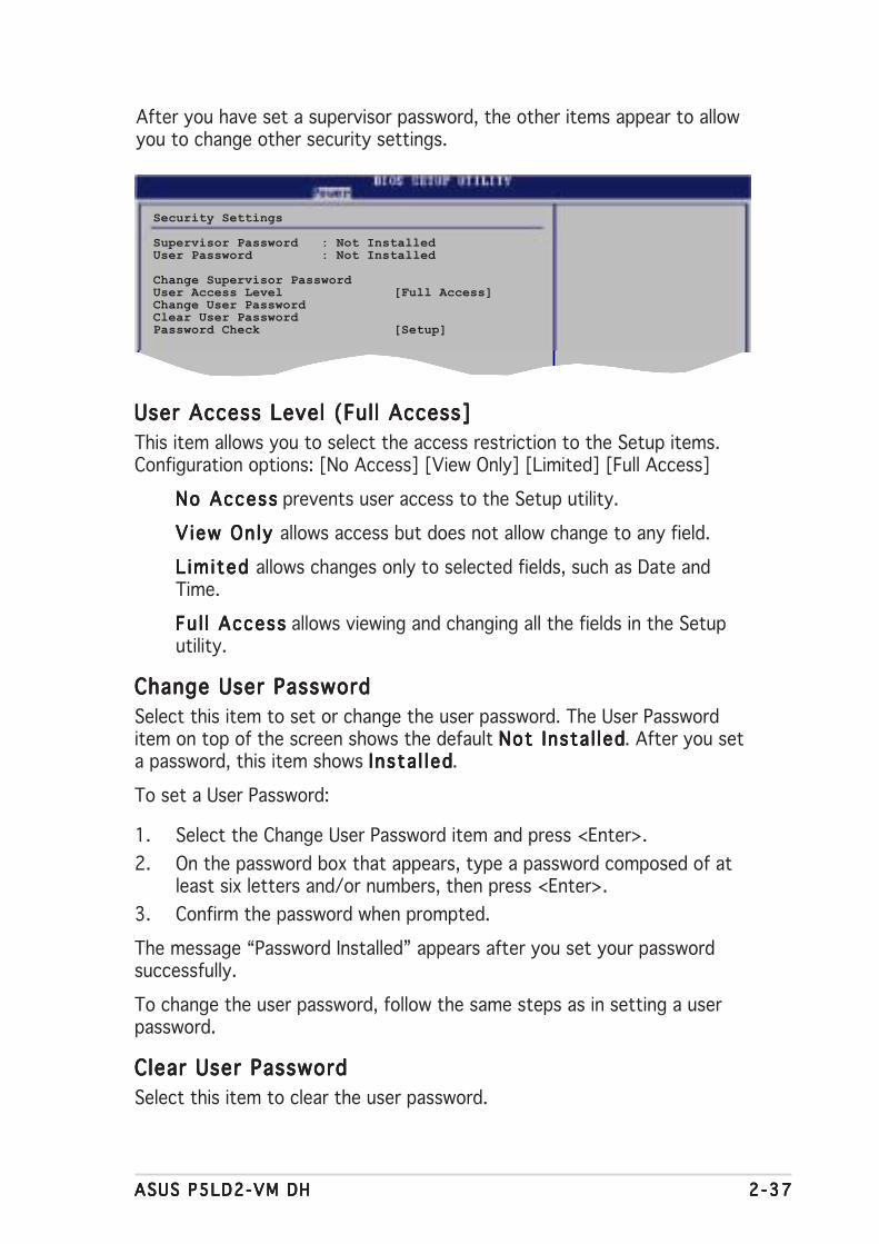
ASUS P5LD2-VM DHASUS P5LD2-VM DHASUS P5LD2-VM DHASUS P5LD2-VM DHASUS P5LD2-VM DH 2 -372 -372 -372 -372 -37
After you have set a supervisor password, the other items appear to allowyou to change other security settings.
User Access Level (Full Access]User Access Level (Full Access]User Access Level (Full Access]User Access Level (Full Access]User Access Level (Full Access]This item allows you to select the access restriction to the Setup items.Configuration options: [No Access] [View Only] [Limited] [Full Access]
No AccessNo AccessNo AccessNo AccessNo Access prevents user access to the Setup utility.
V iew Only V iew Only V iew Only V iew Only V iew Only allows access but does not allow change to any field.
L imited L imited L imited L imited L imited allows changes only to selected fields, such as Date andTime.
Fu l l AccessFu l l AccessFu l l AccessFu l l AccessFu l l Access allows viewing and changing all the fields in the Setuputility.
Change User PasswordChange User PasswordChange User PasswordChange User PasswordChange User PasswordSelect this item to set or change the user password. The User Passworditem on top of the screen shows the default Not Insta l ledNot Insta l ledNot Insta l ledNot Insta l ledNot Insta l led. After you seta password, this item shows Insta l ledInsta l ledInsta l ledInsta l ledInsta l led.
To set a User Password:
1. Select the Change User Password item and press <Enter>.2. On the password box that appears, type a password composed of at
least six letters and/or numbers, then press <Enter>.3. Confirm the password when prompted.
The message “Password Installed” appears after you set your passwordsuccessfully.
To change the user password, follow the same steps as in setting a userpassword.
Clear User PasswordClear User PasswordClear User PasswordClear User PasswordClear User PasswordSelect this item to clear the user password.
Security Settings
Supervisor Password : Not InstalledUser Password : Not Installed
Change Supervisor PasswordUser Access Level [Full Access]Change User PasswordClear User PasswordPassword Check [Setup]

2 -382 -382 -382 -382 -38 Chapter 2 : B IOS setupChapter 2 : B IOS setupChapter 2 : B IOS setupChapter 2 : B IOS setupChapter 2 : B IOS setup
If you attempt to exit the Setup program without saving your changes,the program prompts you with a message asking if you want to saveyour changes before exiting. Press <Enter> to save the changes whileexiting.
Password Check [Setup]Password Check [Setup]Password Check [Setup]Password Check [Setup]Password Check [Setup]When set to [Setup], BIOS checks for user password when accessing theSetup utility. When set to [Always], BIOS checks for user password bothwhen accessing Setup and booting the system.Configuration options: [Setup] [Always]
2.7 Exit menu
Pressing <Esc> does not immediately exit this menu. Select one of theoptions from this menu or <F10> from the legend bar to exit.
The Exit menu items allow you to load the optimal or failsafe default valuesfor the BIOS items, and save or discard your changes to the BIOS items.
Exit Options
Exit & Save ChangesExit & Discard ChangesDiscard Changes
Load Setup Defaults
Exit & Save ChangesExit & Save ChangesExit & Save ChangesExit & Save ChangesExit & Save ChangesOnce you are finished making your selections, choose this option from theExit menu to ensure the values you selected are saved to the CMOS RAM.An onboard backup battery sustains the CMOS RAM so it stays on evenwhen the PC is turned off. When you select this option, a confirmationwindow appears. Select Ok Ok Ok Ok Ok to save changes and exit.
ASUS P5LD2-VM DHASUS P5LD2-VM DHASUS P5LD2-VM DHASUS P5LD2-VM DHASUS P5LD2-VM DH 2 -392 -392 -392 -392 -39
Exit & Discard ChangesExit & Discard ChangesExit & Discard ChangesExit & Discard ChangesExit & Discard ChangesSelect this option only if you do not want to save the changes that youmade to the Setup program. If you made changes to fields other thanSystem Date, System Time, and Password, the BIOS asks for a confirmationbefore exiting.
Discard ChangesDiscard ChangesDiscard ChangesDiscard ChangesDiscard ChangesThis option allows you to discard the selections you made and restore thepreviously saved values. After selecting this option, a confirmation appears.Select Ok Ok Ok Ok Ok to discard any changes and load the previously saved values.
Load Setup DefaultsLoad Setup DefaultsLoad Setup DefaultsLoad Setup DefaultsLoad Setup DefaultsThis option allows you to load the default values for each of theparameters on the Setup menus. When you select this option or if youpress <F5>, a confirmation window appears. Select Ok Ok Ok Ok Ok to load defaultvalues. Select Ex it & Save ChangesEx it & Save ChangesEx it & Save ChangesEx it & Save ChangesEx it & Save Changes or make other changes beforesaving the values to the non-volatile RAM.

2 -402 -402 -402 -402 -40 Chapter 2 : B IOS setupChapter 2 : B IOS setupChapter 2 : B IOS setupChapter 2 : B IOS setupChapter 2 : B IOS setup

ASUS P5LD2-VM DHASUS P5LD2-VM DHASUS P5LD2-VM DHASUS P5LD2-VM DHASUS P5LD2-VM DH 3 - 13 - 13 - 13 - 13 - 1
3Softwaresupport
This chapter describes the contentsof the support CD that comes withthe motherboard package.

3 - 23 - 23 - 23 - 23 - 2 Chapter 3 : Software supportChapter 3 : Software supportChapter 3 : Software supportChapter 3 : Software supportChapter 3 : Software support
If Auto run Auto run Auto run Auto run Auto run is NOT enabled in your computer, browse the contents ofthe support CD to locate the file ASSETUP.EXE from the BIN folder.Double-click the ASSETUP .EXEASSETUP .EXEASSETUP .EXEASSETUP .EXEASSETUP .EXE to run the CD.
C l i c k an i t em to i n s ta l lC l i c k an i t em to i n s ta l lC l i c k an i t em to i n s ta l lC l i c k an i t em to i n s ta l lC l i c k an i t em to i n s ta l l
3.1 Installing an operating systemThis motherboard supports Windows® 2000/XP/2003 Server operatingsystems (OS). Always install the latest OS version and correspondingupdates to maximize the features of your hardware.
3.2 Support CD informationThe support CD that came with the motherboard package contains thedrivers, software applications, and utilities that you can install to avail allmotherboard features.
3.2.13.2.13.2.13.2.13.2.1 Running the support CDRunning the support CDRunning the support CDRunning the support CDRunning the support CDPlace the support CD to the optical drive. The CD automatically displays theDr ivers Dr ivers Dr ivers Dr ivers Dr ivers menu if Autorun is enabled in your computer.
• Motherboard settings and hardware options vary. Use the setupprocedures presented in this chapter for reference only. Refer toyour OS documentation for detailed information.
• Make sure that you install Windows® 2000 Service Pack 4 or theWindows® XP Service Pack 1 or later versions before installing thedrivers for better compatibility and system stability.
The contents of the support CD are subject to change at any timewithout notice. Visit the ASUS website(www.asus.com) for updates.
C l i c k an i con toC l i c k an i con toC l i c k an i con toC l i c k an i con toC l i c k an i con tod i sp l ay suppo r td i sp l ay suppo r td i sp l ay suppo r td i sp l ay suppo r td i sp l ay suppo r tCD/mothe rboa rdCD/mothe rboa rdCD/mothe rboa rdCD/mothe rboa rdCD/mothe rboa rdi n f o rmat i oni n f o rmat i oni n f o rmat i oni n f o rmat i oni n f o rmat i on

ASUS P5LD2-VM DHASUS P5LD2-VM DHASUS P5LD2-VM DHASUS P5LD2-VM DHASUS P5LD2-VM DH 3 - 33 - 33 - 33 - 33 - 3
3.2.23.2.23.2.23.2.23.2.2 Drivers menuDrivers menuDrivers menuDrivers menuDrivers menuThe drivers menu shows the available device drivers if the system detectsinstalled devices. Install the necessary drivers to activate the devices.
QFE DriverQFE DriverQFE DriverQFE DriverQFE DriverInstalls the Quick Fix Engineering (QFE) driver.
Intel Chipset Inf Update ProgramIntel Chipset Inf Update ProgramIntel Chipset Inf Update ProgramIntel Chipset Inf Update ProgramIntel Chipset Inf Update ProgramThis item installs the Intel® Chipset INF Update Program. This driver enablesPlug-n-Play INF support for the Intel® chipset components on themotherboard. When installed to the target system, this driver provides themethod for configuring the chipset components.
You can install this utility using three different modes: interactive, silent, orunattended preload. Installing the driver in interactive mode requires userinput during installation. User input is not required when installing the driverin silent or unattended preload modes. Refer to the online help or readmefile that came with the utility for details.
Make Intel RAID Driver DiskMake Intel RAID Driver DiskMake Intel RAID Driver DiskMake Intel RAID Driver DiskMake Intel RAID Driver DiskCreates an Intel RAID driver disk.
Intel(R) Graphics Accelerator DriverIntel(R) Graphics Accelerator DriverIntel(R) Graphics Accelerator DriverIntel(R) Graphics Accelerator DriverIntel(R) Graphics Accelerator DriverInstalls the Intel® Graphics Accelerator driver.
Realtek Audio DriverRealtek Audio DriverRealtek Audio DriverRealtek Audio DriverRealtek Audio DriverInstalls the Realtek® ALC882 high-definition audio driver and application.
This feature appears only under Microsoft Windows XP system.
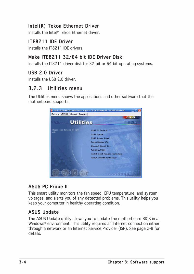
3 - 43 - 43 - 43 - 43 - 4 Chapter 3 : Software supportChapter 3 : Software supportChapter 3 : Software supportChapter 3 : Software supportChapter 3 : Software support
3.2.33.2.33.2.33.2.33.2.3 Utilities menuUtilities menuUtilities menuUtilities menuUtilities menuThe Utilities menu shows the applications and other software that themotherboard supports.
Intel(R) Tekoa Ethernet DriverIntel(R) Tekoa Ethernet DriverIntel(R) Tekoa Ethernet DriverIntel(R) Tekoa Ethernet DriverIntel(R) Tekoa Ethernet DriverInstalls the Intel® Tekoa Ethernet driver.
ITE8211 IDE DriverITE8211 IDE DriverITE8211 IDE DriverITE8211 IDE DriverITE8211 IDE DriverInstalls the IT8211 IDE drivers.
Make ITE8211 32/64 bit IDE Driver DiskMake ITE8211 32/64 bit IDE Driver DiskMake ITE8211 32/64 bit IDE Driver DiskMake ITE8211 32/64 bit IDE Driver DiskMake ITE8211 32/64 bit IDE Driver DiskInstalls the IT8211 driver disk for 32-bit or 64-bit operating systems.
USB 2.0 DriverUSB 2.0 DriverUSB 2.0 DriverUSB 2.0 DriverUSB 2.0 DriverInstalls the USB 2.0 driver.
ASUS PC Probe I IASUS PC Probe I IASUS PC Probe I IASUS PC Probe I IASUS PC Probe I IThis smart utility monitors the fan speed, CPU temperature, and systemvoltages, and alerts you of any detected problems. This utility helps youkeep your computer in healthy operating condition.
ASUS UpdateASUS UpdateASUS UpdateASUS UpdateASUS UpdateThe ASUS Update utility allows you to update the motherboard BIOS in aWindows® environment. This utility requires an Internet connection eitherthrough a network or an Internet Service Provider (ISP). See page 2-8 fordetails.

ASUS P5LD2-VM DHASUS P5LD2-VM DHASUS P5LD2-VM DHASUS P5LD2-VM DHASUS P5LD2-VM DH 3 - 53 - 53 - 53 - 53 - 5
ASUS Screen SaverASUS Screen SaverASUS Screen SaverASUS Screen SaverASUS Screen SaverInstalls the ASUS screen saver.
Microsoft DirectX 9.0cMicrosoft DirectX 9.0cMicrosoft DirectX 9.0cMicrosoft DirectX 9.0cMicrosoft DirectX 9.0cInstalls the Microsoft® DirectX 9.0c driver.
Adobe Reader V7.0Adobe Reader V7.0Adobe Reader V7.0Adobe Reader V7.0Adobe Reader V7.0Installs the Adobe Reader V7.0
Anti-Virus Uti l ityAnti-Virus Uti l ityAnti-Virus Uti l ityAnti-Virus Uti l ityAnti-Virus Uti l ityInstalls the PC-cillin anti-virus program. View the online help for detailedinformation.
Intel Quick Resume Technology DriverIntel Quick Resume Technology DriverIntel Quick Resume Technology DriverIntel Quick Resume Technology DriverIntel Quick Resume Technology DriverInstalls the Intel® Quick Resume Technology Driver (QRTD) for instant on/off (after initial boot, when activated) capability of an Intel® Viiv™technology-based PC, allowing it to behave like a consumer electronicdevice.
Intel Viiv SoftwareIntel Viiv SoftwareIntel Viiv SoftwareIntel Viiv SoftwareIntel Viiv SoftwareInstalls the Intel® Viiv™ utility that transforms your PC into anentertainment center, allowing you to enjoy and share digital multi-mediacontent. With Intel®®®®® ViiV™ Technology-based computers, you can record,playback, organize, and edit digital media content easily.
This feature appears only when Microsoft Windows XP Media CenterEdition is installed.
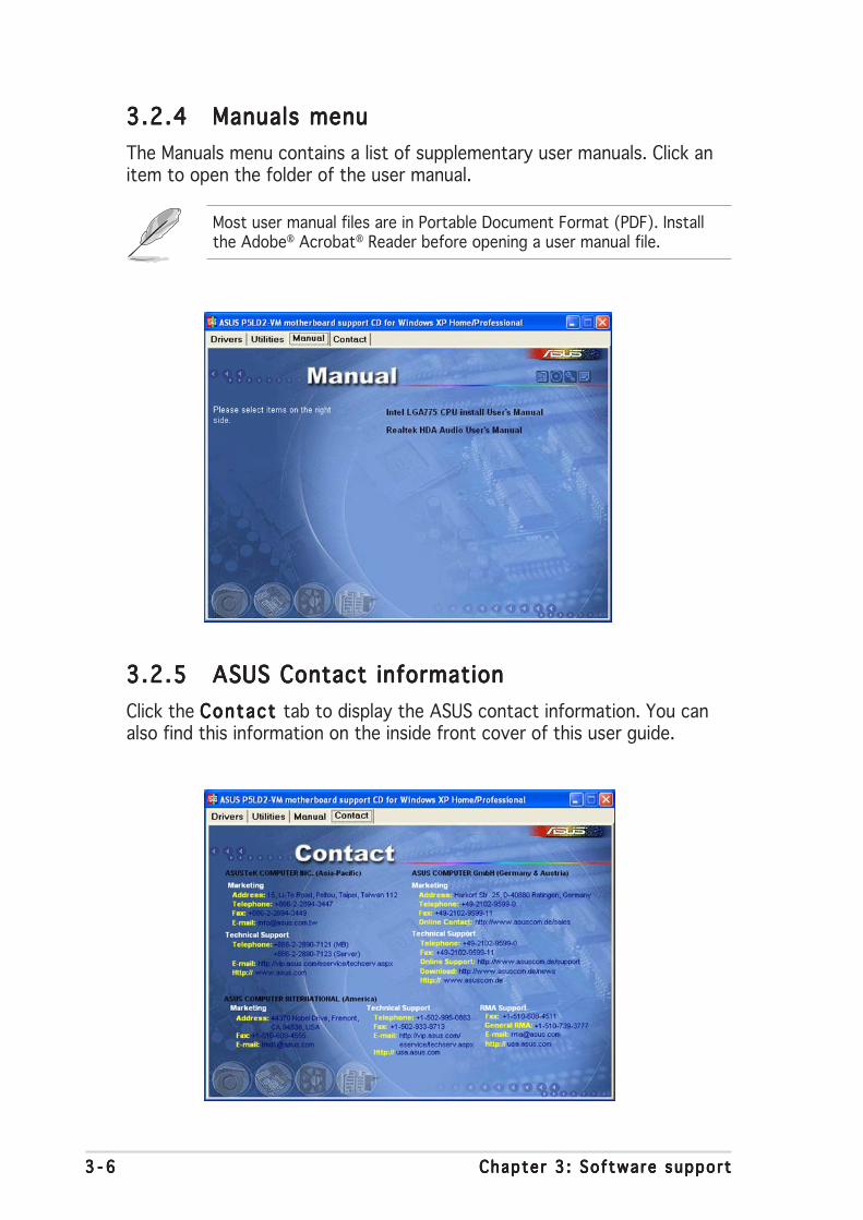
3 - 63 - 63 - 63 - 63 - 6 Chapter 3 : Software supportChapter 3 : Software supportChapter 3 : Software supportChapter 3 : Software supportChapter 3 : Software support
3.2.53.2.53.2.53.2.53.2.5 ASUS Contact informationASUS Contact informationASUS Contact informationASUS Contact informationASUS Contact informationClick the Contact Contact Contact Contact Contact tab to display the ASUS contact information. You canalso find this information on the inside front cover of this user guide.
3.2.43.2.43.2.43.2.43.2.4 Manuals menuManuals menuManuals menuManuals menuManuals menuThe Manuals menu contains a list of supplementary user manuals. Click anitem to open the folder of the user manual.
Most user manual files are in Portable Document Format (PDF). Installthe Adobe® Acrobat® Reader before opening a user manual file.
ASUS P5LD2-VM DHASUS P5LD2-VM DHASUS P5LD2-VM DHASUS P5LD2-VM DHASUS P5LD2-VM DH
ACPU features
The Appendix describes the CPUfeatures that the motherboardsupports.

A - 2A - 2A - 2A - 2A - 2 Append ix : CPU featuresAppend ix : CPU featuresAppend ix : CPU featuresAppend ix : CPU featuresAppend ix : CPU features
A.1 Intel® EM64T
• The motherboard is fully compatible with Intel® Pentium® 4 LGA775processors running on 32-bit operating systems.
• The motherboard comes with a BIOS file that supports EM64T. Youcan download the latest BIOS file from the ASUS website(www.asus.com/support/download/) if you need to update the BIOSfile. See Chapter 2 for details.
• Visit www.intel.com for more information on the EM64T feature.
• Visit www.microsoft.com for more information on Windows® 64-bit OS.
Using the IntelUsing the IntelUsing the IntelUsing the IntelUsing the Intel®®®®® EM64T feature EM64T feature EM64T feature EM64T feature EM64T featureTo use the Intel® EM64T feature:
1. Install an Intel® Pentium® 4 CPU that supports the Intel® EM64T.2. Install a 64-bit operating system (Windows® XP Professional x64
Edition or Windows® Server 2003 x64 Edition).3. Install the 64-bit drivers for the motherboard components and devices
from the support CD.4. Install the 64-bit drivers for expansion cards or add-on devices, if any.
Refer to the expansion card or add-on device(s) documentation, or visitthe related website, to verify if the card/device supports a 64-bit system.
A.2 Enhanced Intel SpeedStep®
Technology (EIST)
• The motherboard comes with a BIOS file that supports EIST. You candownload the latest BIOS file from the ASUS website(www.asus.com/support/download/) if you need to update theBIOS. See Chapter 2 for details.
• Visit www.intel.com for more information on the EIST feature.
A.2.1A.2.1A.2.1A.2.1A.2.1 System requirementsSystem requirementsSystem requirementsSystem requirementsSystem requirementsBefore using EIST, check your system if it meets the followingrequirements:
• Intel® Pentium® 4 processor with EIST support• BIOS file with EIST support• Operating system with EIST support (Windows® XP SP2/Windows®
Server 2003 SP1/Linux 2.6 kernel or later versions)

ASUS P5LD2-VM DHASUS P5LD2-VM DHASUS P5LD2-VM DHASUS P5LD2-VM DHASUS P5LD2-VM DH
A.2.2A.2.2A.2.2A.2.2A.2.2 Using the EISTUsing the EISTUsing the EISTUsing the EISTUsing the EIST
To use the EIST feature:
1. Turn on the computer, then enter the BIOS Setup.2. Go to the Advanced MenuAdvanced MenuAdvanced MenuAdvanced MenuAdvanced Menu, highlight CPU ConfigurationCPU ConfigurationCPU ConfigurationCPU ConfigurationCPU Configuration,
then press <Enter>.3. Set the Intel(R) SpeedStep TechnologyIntel(R) SpeedStep TechnologyIntel(R) SpeedStep TechnologyIntel(R) SpeedStep TechnologyIntel(R) SpeedStep Technology item to [Automatic],
then press <Enter>. See page 2-24 for details.4. Press <F10> to save your changes and exit the BIOS setup.5. After the computer restarts, right click on a blank space on the desktop,
then select Properties Properties Properties Properties Properties from the pop-up menu.6. When the Display PropertiesDisplay PropertiesDisplay PropertiesDisplay PropertiesDisplay Properties
window appears, click theScreen Saver Screen Saver Screen Saver Screen Saver Screen Saver tab.
7. Click the Power Power Power Power Power button on theMonitor power section to openthe Power OptionsPower OptionsPower OptionsPower OptionsPower OptionsProperties Properties Properties Properties Properties window.
8. On the Power schemesPower schemesPower schemesPower schemesPower schemessection, click , then select anyoption except Home/Off iceHome/Off iceHome/Off iceHome/Off iceHome/Off iceDesktopDesktopDesktopDesktopDesktop or A lways OnAlways OnAlways OnAlways OnAlways On.
9. Click App lyApp lyApp lyApp lyApp ly, then click O KO KO KO KO K.10. Close the Disp lay Propert iesDisp lay Propert iesDisp lay Propert iesDisp lay Propert iesDisp lay Propert ies
window.After you adjust the powerscheme, the CPU internalfrequency slightly decreaseswhen the CPU loading is low.
The screen displays and procedures may vary depending on theoperating system.

A - 4A - 4A - 4A - 4A - 4 Append ix : CPU featuresAppend ix : CPU featuresAppend ix : CPU featuresAppend ix : CPU featuresAppend ix : CPU features
A.3 Intel® Hyper-Threading Technology
• The motherboard supports Intel® Pentium® 4 LGA775 processorswith Hyper-Threading Technology.
• Hyper-Threading Technology is supported under Windows® XP/2003Server and Linux 2.4.x (kernel) and later versions only. Under Linux, usethe Hyper-Threading compiler to compile the code. If you are using anyother operating systems, disable the Hyper-Threading Techonologyitem in the BIOS to ensure system stability and performance.
• Installing Windows® XP Service Pack 1 or later version is recommended.
• Make sure to enable the Hyper-Threading Technology item in BIOSbefore installing a supported operating system.
• For more information on Hyper-Threading Technology, visitwww.intel.com/info/hyperthreading.
Using the Hyper-Threading TechnologyUsing the Hyper-Threading TechnologyUsing the Hyper-Threading TechnologyUsing the Hyper-Threading TechnologyUsing the Hyper-Threading Technology
To use the Hyper-Threading Technology:
1. Install an Intel® Pentium® 4 CPU that supports Hyper-ThreadingTechnology.
2. Power up the system and enter the BIOS Setup. Under the AdvancedAdvancedAdvancedAdvancedAdvancedMenuMenuMenuMenuMenu, make sure that the item Hyper-Threading Technology Hyper-Threading Technology Hyper-Threading Technology Hyper-Threading Technology Hyper-Threading Technology isset to Enab ledEnab ledEnab ledEnab ledEnab led.The BIOS item appears only if you installed a CPU that supportsHyper-Threading Technology.
3. Restart the computer.