front panel programming - texmate panel programming this programming code sheet (pcs) is a quick...
TRANSCRIPT

Tiger 320 Series Programming Code SheetDraft Copy. Code Version V3.08a
Texmate Inc. Tel. (760) 598 9899 • www.texmate.com 12 February, 2005 Prog. Code Sheet V3.08a (NZ101)
PROGRAMMING CODE SHEETTTiiggeerr 332200 SSeerriieess
Code blankingCode blanking blanks out all function codesnot required by the application.This meansthat specific procedures such as recalibra-tion and setpoint reprogramming can beachieved in a few simple steps from thefront panel buttons.
To turn code blanking and macro settingsOFF, carry out the Code Blanking andMacro Check on Page 3.
Display text editingThis function allows displayed text, suchas setpoint titles, to be edited to suit yourapplications.
For example, a setpoint could be editedto read [TNKLo] for tank level low, or[brKoF] for brake off.
Configuration data copyingThis function allows the current meterconfiguration settings to be copied andsaved for later referral or for restoration.
Programming Tips1) Use the button to step through the codes
of the Main or Setpoint Programming Mode.
2) To save a Main Programming Mode code set-ting and return directly to the operational dis-
play, press the button and then the
and buttons at the same time.
3) To save a Setpoint Programming Mode set-ting and return directly to the operational dis-
play, press the button and then the
and buttons at the same time.
4) When configuring the three-digit code and
setpoint settings, pressing the and buttons at the same time increases the dis-played parameter in increments of 100counts.
PP
PP
P
Front panel programmingThis programming code sheet (PCS) is aquick reference document that allows you toquickly view the meter's programming codes.
When you become familiar with the meter andthe programming code structure, the PCS canbe used in place of the user manual.
Programming via PC
Meter configuration utility programWith a serial output module installed, themeter can be fully configured through themeter configuration utility program. Inaddition to all application function settings,the configuration program also providesaccess to added features such as:
• Code blanking.
• Display text editing.
• Configuration data copying.
• Downloading macros to the meter.
Tamper-proof settingsAll Tiger 320 Series meters havetamper-proof lockout switches to pre-vent users’ configuration settings frombeing inadvertently changed.
Code blanking is also used (via thePC) to blank out codes not used, mak-ing them operator tamper-proof, butleaving selected codes open for oper-ator adjustment.
MacrosTexmate has a growing library of macrosto suit a wide range of standard cus-tomer applications. Macros can beinstalled in the meter, via the compiler orconfiguration program, and run automat-ically when the meter is powered up.
Prog. SP1 SP2 SP4SP3 SP5 SP6
TEXMATE
Press1
To configure the meter’s programming codesfrom the front panel, the meter uses the threeright-hand side display digits. These areknown as the 1st, 2nd, and 3rd digits and canbe seen in the diagram below.
Prog. SP1 SP2 SP4SP3 SP5 SP6
Operational Display
1stDigit
2ndDigit
3rdDigit
The logic diagram on Page 4 shows the codestructure of the Tiger 320 Series meter range.Also, the difference between the E and T ver-sion of the Tiger range is described. The dia-grams on the following pages show the three-digit settings available for each code.
Note:All displays shown in this codesheet are for a 5-digit, 7-seg-ment LED display. Other Tiger320 Series displays will beslightly different.
ContentsInitial Setup Procedures . . . . . . . . . . . . . . . . . . . . . . . . . . . . .2
Tiger 320 Series Code Logic Diagram . . . . . . . . . . . . . . . . .4
CALIBRATION MODE . . . . . . . . . . . . . . . . . . . . . . . . . . . . . .5
CODE 1 . . . . . . . . . . . . . . . . . . . . . . . . . . . . . . . . . . . . . . . . .6
CODE 2 . . . . . . . . . . . . . . . . . . . . . . . . . . . . . . . . . . . . . . . . .7
CODES 3 to 5 . . . . . . . . . . . . . . . . . . . . . . . . . . . . . . . . . . . .8
CODES 6 to 9 . . . . . . . . . . . . . . . . . . . . . . . . . . . . . . . . . . . .9
CODE 10 . . . . . . . . . . . . . . . . . . . . . . . . . . . . . . . . . . . . . . .10
SETPOINT PROGRAMMING MODE – SPC_1 to SPC_6 .11
Detailed Descriptions of Setpoint Functions . . . . . . . . . . . .14
Customer Code Settings – Main Programming Mode . . . . .15
Customer Code Settings – Setpoint Programming Mode . .18
Commonly Used Registers . . . . . . . . . . . . . . . . . . . . . . . . .19
User Notes . . . . . . . . . . . . . . . . . . . . . . . . . . . . . . . . . . . . .20
Note:3-digit programming codes arespecified within square brack-ets [XXX].
If an X appears in the descrip-tion of a 3-digit programmingcode or in a configuration pro-cedure, this means that morethan one choice can be made,or any number displayed inthat digit is not relevant to thefunction being explained.

Tiger 320 Series Programming Code SheetDraft Copy. Code Version V3.08a
Texmate Inc. Tel. (760) 598 9899 • www.texmate.com 22 February, 2005 Prog. Code Sheet V3.08a (NZ101)
SP1 SP2 SP3 SP4 SP5 SP6Prog.
SP1 SP2 SP3 SP4 SP5 SP6Prog.
SP1 SP2 SP3 SP4 SP5 SP6Prog.
SP1 SP2 SP3 SP4 SP5 SP6Prog.
SP1 SP2 SP3 SP4 SP5 SP6Prog.
MODEL &SOFTWARE CODE VERSION CHECK
Pressthenonce
release
PressandholdStep 1
Step 2
Step 3The above displays togglesthree times before returning tothe operational display
SP1 SP2 SP3 SP4 SP5 SP6Prog.
Operational Display
Operational Display
Example
Releaseafter
pressingProg.
ModelNumber
TypicalSoftwareVersionNumber
Press and holdthe and buttons
While holding bothbuttons, press the Prog.button then releaseall three buttons
Programming Tip
The Model and Software Code Version check-ing procedure can be performed at any timewithout interfering with other configurationsettings.
STSTARART HERET HERE
a
b
c
Model No: ............................................................................
Software Version No: ..................................................
Customer ID: ......................................................................
Macro ID: ..............................................................................
Initial Setup Procedures
Model and Software Code Version CheckThe meter model and software code version number can bechecked at any time while in the operational display using thefollowing procedure.
Before configuring the meter, carry out the following meterconfiguration checks:
• Model and software code version check.
• Code blanking and macro check.
After powering-up the meter, check the model and softwarecode version number and note this below.
Tiger 320 Series Programming Code SheetDraft Copy. Code Version V3.08a
Texmate Inc. Tel. (760) 598 9899 • www.texmate.com 32 February, 2005 Prog. Code Sheet V3.08a (NZ101)
Prog. SP1 SP2 SP4SP3 SP5 SP6
TEXMATE
Prog. SP1 SP2 SP4SP3 SP5 SP6
TEXMATE
Prog. SP1 SP2 SP4SP3 SP5 SP6
TEXMATE
Pressandhold
Step 1
Step 2While holding bothbuttons, press the Prog.button.
Step 2
Step 3
Operational Display
Example
Releaseafter
pressingProg.
Press
CodeBlanking
Press and holdthe and buttons
While holding bothbuttons, press the Prog.button.
Prog. SP1 SP2 SP4SP3 SP5 SP6
TEXMATE
Release thethe and buttons and holdthe Prog. buttonfor approx. 1 secthen release
Releaseafter 1
sec
Prog. SP1 SP2 SP4SP3 SP5 SP6
TEXMATE
Step 4Press the button to switchcode blanking OFF
Press1
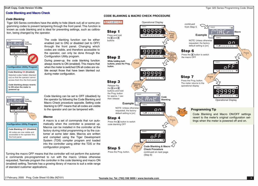
NOTE: Unless otherwiserequested, the factorydefault setting is [on]
Code Blanking & Macro Check Procedurecontinued on next page(Step 6)
Prog. SP1 SP2 SP4SP3 SP5 SP6
TEXMATE
Press1Step 5
Press the Prog. button.
Programming Tip
Code Blanking and Macro ON/OFF settingsrevert to the meter’s original configuration set-tings when the meter is powered off and on.
Prog. SP1 SP2 SP4SP3 SP5 SP6
TEXMATE
Operational Display
Prog. SP1 SP2 SP4SP3 SP5 SP6
TEXMATE
Press1
Step 7Press the Prog. button.The meter returns to theoperational display
continuedfrom Step 5
Prog. SP1 SP2 SP4SP3 SP5 SP6
TEXMATE
ExampleMacro
Prog. SP1 SP2 SP4SP3 SP5 SP6
TEXMATE
Step 6Press the button to switchthe macro OFF
Press1
NOTE: Unless otherwiserequested, the factorydefault setting is [on]
STSTARART HERET HERE
CODE BLANKING & MACRO CHECK PROCEDURECode Blanking and Macro Check
Code BlankingTiger 320 Series controllers have the ability to hide (blank out) all or some pro-gramming codes to prevent tampering through the front panel. This function isknown as code blanking and is ideal for preventing settings, such as calibra-tion, being changed by the operator.
MacrosA macro is a set of commands that run auto-matically when the controller is powered up.Macros can be installed in the controller at thefactory during initial programming or by the cus-tomer at some later date. Macros are writtenand compiled using the Tiger DevelopmentSystem (TDS) compiler program and loadedinto the controller using either the TDS or theconfiguration program.
Prog. SP1 SP2 SP4SP3 SP5 SP6
TEXMATE
Prog. SP1 SP2 SP4SP3 SP5 SP6
TEXMATE
Prog. SP1 SP2 SP4SP3 SP5 SP6
TEXMATE
Prog. SP1 SP2 SP4SP3 SP5 SP6
TEXMATE
CodeBlanking
Press1
Configuration Utility Program
Code Blanking ON (Enabled)
Selected codes hidden (blankedout) so that the operator cannotaccess them thru the front panel
Code blanking always revertsto ON when the meter ispowered up
CodeBlanking
Configuration Utility Program
Code Blanking OFF (Disabled)
All codes are now visible andaccessible to the operator thruthe front panel
Press1
Code blanking can be set to OFF (disabled) bythe operator by following the Code Blanking andMacro Check procedure opposite. Setting codeblanking to OFF means that all codes are visibleto the operator and can be tampered with.
The code blanking function can be eitherenabled (set to ON) or disabled (set to OFF)through the front panel. Changing whichcodes are visible, and therefore accessible tothe operator, can only be done through theConfiguration Utility program.
During power-up, the code blanking functionalways reverts to ON (enabled).This means thatwhen the meter is switched ON all codes are vis-ible except those that have been blanked outduring meter configuration.
Turning the macro OFF means that the controller will not perform the automat-ic commands pre-programmed to run with the macro. Unless otherwiserequested, Texmate program the controller in the code blanking and macro ON(enabled) setting. Texmate has a growing library of macros to suit a wide rangeof standard customer applications.

Tiger 320 Series Programming Code SheetDraft Copy. Code Version V3.08a
Texmate Inc. Tel. (760) 598 9899 • www.texmate.com 42 February, 2005 Prog. Code Sheet V3.08a (NZ101)
Tiger 320 Series Code Logic Diagram
To enter press the and buttons at the same time
P
Calibration Modes for Input and Output
Code 1 – Display Configuration
Code 2 – CH1 Measurement Task & Sampling Rate
Code 3 – CH1 Post Processing & Serial Mode Functions
Code 4 – CH2 Measurement Task & 32-point Linearization
Code 5 – CH3 Functions
Code 6 – CH4 Functions
Code 7 – Result Processing
Code 8 – Data Logging & Print Mode
Code 9 – Functions for Digital Input Pins
[CAL]
[Cod_1]
[Cod_2]
[Cod_3]
[Cod_4]
[Cod_5]
[Cod_6]
[Cod_7]
[Cod_8]
[Cod_9]
To enter press the and buttons at the same time
P
Setpoint 1[SP_1]
Setpoint Activation Values Mode
Setpoint 2[SP_2]
Setpoint 3[SP_3]
Setpoint 4[SP_4]
Setpoint 5[SP_5]
Setpoint 6[SP_6]
Enter these menus to set setpoint(SP) activation values
Setpoint 1[SPC_1]
Setpoint & Relay Control Settings Mode
Setpoint 2[SPC_2]
Setpoint 3[SPC_3]
Setpoint 4[SPC_4]
Setpoint 5[SPC_5]
Setpoint 6[SPC_6]
Enter these menus to configure SP controlsettings
See Page 5 for code settings to calibrate the meter’s input and output signals.
See Page 6 for code settings to configure the setpoint annunciators and otherdisplay functions.
See Page 7 for code settings to configure the CH1 measurement task and sam-pling rate.
See Page 8 for code settings to configure CH1 post processing and serialmode functions.
See Page 8 for code settings to configure the second channel (CH2) meas-urement task and 32-point linearization settings when using dual input signalconditioners.
See Page 8 for code settings to configure the third channel (CH3) when usingtriple input signal conditioners.
See Page 9 for code settings to configure the fourth channel (CH4) whenusing quad input signal conditioners.
See Page 9 for code settings to configure the meter for processing the resultof CH1 and CH2.
See Page 9 for code settings to configure data logging and data printingusing the meter.
See Page 9 for code settings to configure the meter for inputs from externalsources through the digital input pins.
The Setpoint andRelay ControlSettings diagramon Pages 8, 9, and10 shows the threedigit configurationsettings that areapplied individuallyto each setpoint.
Display Brightness[bri]Allows you to adjust the display brightness in a range of 8 settings. 0 beingdull, 7 being bright.
Code 10 – Bargraph Setup[Cod10]See Page 10 for code settings to configure the meter’s bargraph display.
Main Programming Mode Setpoint Programming Mode
P
P
P
P
P
P
P
P
P
P
P
P
P
P
P
P
P
P
P
P
P
P
P
Prog. SP1 SP2 SP4SP3 SP5 SP6
Operational Display
Prog. SP1 SP2 SP4SP3 SP5 SP6
Operational Display
P
Default setting = 18000
Default setting = –18000
Default setting = 5000
Default setting = –5000
Default setting = 10000
Default setting = –10000
Prog. SP1 SP2 SP4SP3 SP5 SP6
Operational Display
Tiger 320 Series Programmable Meter Controllers (PMCs) come intwo versions: the economy E version, or the top-of-the-line T version.
The standard E version comes with 4 kilobits of EEPROM installed,whereas the standard T version comes with 32 kilobits of EEPROMInstalled. Also, the T version can have a macro installed.
The standard 4-kilobit E version can be upgraded to 32 or 512 kilobits.The standard 32-kilobit T version can be upgraded to 512 kilobits.Theamount of EEPROM installed in the controller determines the range offunctions it is capable of performing. The following table lists the func-tions that require specific amounts of memory.
Version FunctionsMemory(kilobits)
Remarks
E 1 linearization table4 (standard) Table 1 is available tobe applied to chan-nels 1 to 4 and result.
4 linearization tables32 Tables 1 to 4 areavailable to beapplied to channels 1and 2 and result.
Table 3 can be appliedto channel 3.
Table 4 can be appliedto channel 4.
All four tables can becascaded to form asingle 125-point lin-earization table avail-able to be applied tochannels 1 and 2 andresult.
Data logging512 With 512 kilobitsinstalled, the controllercan perform data log-ging functions alongwith complete lin-earization functionali-ty. With a real-timeclock installed, dateand time stamps canbe included.
T 4 linearization tables32 (standard) As for E version with32 kilobits installed.
Macro programming A macro can be pro-grammed to suit auser's logic controlapplication.
Data logging512 As for E version with512 kilobits installed,but with macro pro-gramming functionali-ty available.
E/T Versions of Tiger 320 Series Programmable Meter Controller
Tiger 320 Series Programming Code SheetDraft Copy. Code Version V3.08a
Texmate Inc. Tel. (760) 598 9899 • www.texmate.com 52 February, 2005 Prog. Code Sheet V3.08a (NZ101)
0 Functions Activatedby Pressing thePROGRAM Button
1 CalibrationProcedures
2 Related CalibrationFunctions
3 -
CALIBRATION MODES FOR INPUT AND OUTPUT
0 No function
1 On Demand TARE from the PROGRAM button
2 On Demand Single-point Calibration from the PRO-GRAM button (requires single input source)
3 On Demand Two-point Calibration from the PROGRAMbutton (requires dual input source)
4 On Demand Primary Input Compensation Mode fromthe PROGRAM button
5 On Demand Manual Loader Mode (no increase /decrease with HOLD active)
6 -7 -
Note:When in the TARE mode, a decimal point appears at the rightof the display indicating that the tare value is NOT zero.
OBJECT FOR 2nd DIGIT
0 Result1 Channel 12 Channel 23 Channel 34 Channel 4
CALIBRATION MODE
FIRST DIGIT SECOND DIGIT THIRD DIGIT
0 Serial Communications Properties
1 Set Auto Zero Maintenance for 3rd digit
2 Set Averaging Samples & Averaging Window for 3rd digit
3 Totalizer Settings Mode
4 Setup 32-point Linearization Tables
5 Scale Analog Output LOW/HIGH Display Readings
6 -
7 -
Use but-tons to set SPAN
Use buttons to setOFFSET
Use but-tons to set ZERO
Use buttonsto set SCALE
Use buttonsto set SPAN
P P
For detailed calibration procedures, seeCalibration Procedures Supplement (NZ203)
Press the PROGRAM button for 4 seconds to tare the selected channelP
P 4 secs
P 4 secsUse buttons to setZERO
Use buttonsto set SPAN
P 4 secs
P 4 secs
P PUse buttonsto set baud rate
Use but-tons to set parity
Use buttons to setaddress from 1 to 255
Use buttons to set LOWdisplay reading [CAL_L]
Use buttons to setHIGH display reading [CAL_h]
Use buttonsto set CAL_h
Use buttonsto set time period
Use buttons toset total from 1-65535
Select the method of configuring the user defined linearizationtable: manual or auto setup mode. Then set the table number,date, and serial number before setting the linearization points.Or select [init] to re-initialize the default table settings.
P
P
P
P
P
P
Use buttons to set averag-ing samples from 0 to 255 counts
Use buttons to set averagingwindow from 0 to 65535 counts
P
Use buttonsto set AZ_M from 0to 255 counts
P
Auto zero capture band
For detailed calibration procedures, seeCalibration Procedures Supplement
Use buttons to ADJUST primary input compensa-tion value from –19999 to 99999 on CH2 ONLY
Use buttons to settime delay in milliseconds
Except ASCII Mode which uses message terminators:
Use buttonsto set AZ_A from 0 to65535 counts
P
Auto zero motion Auto zero aperture window
0 -1 Analog Output 12 Analog Output 2
THIRD DIGIT
0 -1 Analog Output 12 Analog Output 2
THIRD DIGIT
Note:The input channel setting inthe 3rd digit is not relevant tothe manual setup mode.
0 -1 Total 12 Total 2
THIRD DIGIT
Use buttons to ADJUST analog output 1 or 2 valuefrom –19999 to 99999 via the manual loader output
Default setting 10,000 counts
0 -1 CH12 CH23 CH34 CH4
THIRD DIGIT
P
P
Use buttonsto set Cutoff from–19999 to 32767
P Use buttons toset rollover to ON or OFF
P Use buttonsto set to 7 or 8 bits
If Code 3 set to MasterMode [XX2] ONLY $ = minimum 50 ms delay
* = minimum 2 ms delay
Use buttonsto set input rate
Note:The correct input signal channel must beselected in the 3rd digit when configuring a lin-earization table using the auto setup mode.
Use buttons to setAZ_C from 1 to 254 counts
Rate-of-change in counts/second
This is the default 3rd digit box. If not pointing to another 3rd digitbox, all 2nd digit settings should be regarded as pointing to here.
0 Manual Calibration (requires NO input source)
1 2-point Calibration (requires dual input source)
2 Calibrate Thermocouple (requires K type thermocoupleinput source)
3 Calibrate RTD (requires RTD 385 input source)
4 Calibrate Smart Input Module.Note: This function is not available on all input modules
5 Calibrate Analog Output mA/V (Single analog out requiresmultimeter connected to pins 2 and 3 on Terminal 4)
6 -7 -
Converting °F to °CSee User Notes on Page 20 for a procedure.
21 3
++
DualAnalogOutput(ADV)
Analog OutputTERMINAL 4
All smart input modules have individual calibration procedures.See the specific smart input module data sheet for setup procedures
Use buttonsto set CAL_L
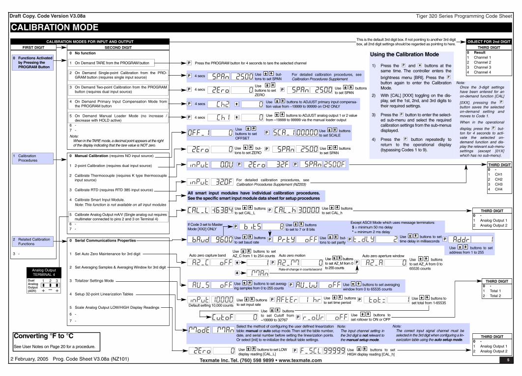
Using the Calibration Mode
1) Press the and buttons at thesame time. The controller enters the
brightness menu [BRI]. Press the button again to enter the CalibrationMode.
2) With [CAL] [XXX] toggling on the dis-play, set the 1st, 2nd, and 3rd digits totheir required settings.
3) Press the button to enter the select-ed sub-menu and select the requiredcalibration settings from the sub-menusdisplayed.
4) Press the button repeatedly toreturn to the operational display(bypassing Codes 1 to 9).
P
P
P
P
Note:Once the 3-digit settingshave been entered for anon-demand function [CAL]
[0XX], pressing the button saves the selectedon-demand setting andmoves to Code 1.
When in the operational
display, press the but-ton for 4 seconds to acti-vate the selected on-demand function and dis-play the relevant sub-menusettings (except [01X]which has no sub-menu).
P
P

Tiger 320 Series Programming Code SheetDraft Copy. Code Version V3.08a
Texmate Inc. Tel. (760) 598 9899 • www.texmate.com 62 February, 2005 Prog. Code Sheet V3.08a (NZ101)
FRONT PANEL ANNUNCIATORS0 ON when Setpoints are ON (relay
energized)1 ON when Setpoints are OFF (relay
de-energized)2 Always OFF. See Note 13 LED SP1 ON indicates RISING sig-
nal trend.LED SP2 ON indicates FALLINGsignal trend.
DISPLAY FUNCTIONS0 Normal Display Mode (i.e. operational display
shows selected register)(updates every 0.5seconds)
1 Manual Loader Mode (Direct display). See Note*2 Update at controlled output rate selected in Code 23 -4 -
5 Select data source as per 3rd digit. See Note 4
6 Select display format as per 3rd digit. See Note 4
7 Select text character as per 3rd digit. See Note 4
SELECT DATA SOURCE FOR0 Primary Display1 Second Display. See Note 22 Third Display. See Note 23 Peak/Valley4 Analog Output 15 Analog Output 26 Totalizer 17 Totalizer 2
CODE 1 – DISPLAY CONFIGURATION
LAST DIGIT ROUNDING0 No rounding1 Rounding by 2’s2 Rounding by 5’s3 Rounding by 10’s
DISPLAY UNITS0 Decimal1 24-hour clock mode
Hours: Minutes:Seconds (6-digit version only)2 12-hour clock mode (12:30 am is displayed as
12:30A. 12:30 pm is displayed as 12:30P)3 24-hour clock mode
Days: Hours:Minutes (6-digit version only)
4 -5 -6 -7 Octal
DECIMAL POINT PLACEMENT0 No decimal point1 XX.XX.XX (6 or 8-digit version only)2 X.XXXXX (6 or 8-digit version only)3 X.XXXX4 X.XXX5 X.XX6 X.X7 Decimal Point set from the rear
(X.XXXXX to XXXXXX).See Note 3.Also See Note 4
DISPLAY FORMAT MODE
CODE 1
0 Result1 Channel 12 Channel 23 Channel 34 Channel 45 Default Display6 Total 17 Total 2
0 Result1 Channel 12 Channel 23 Channel 34 Channel 45 Default Display6 Total 17 Total 2
SELECT DISPLAY FORMAT FOR
SELECT TEXT CHARACTER FOR
FIRST DIGIT SECOND DIGIT THIRD DIGIT
Note 1:LED annunciators are always off, except when the meter is in single channelVOLTAGE or CURRENT mode and Code 3 = [X6X], or Code 7 = [X6X] inwhich case the LEDs indicate which 32-point table has been selected from therear pins (SP1 = Table 1, SP2 = Table 2, SP3 = Table 3, SP4 = Table 4).
Note 2:These options are only for use with meters that have more than one dis-play. With bargraph meters the PRIMARY display is the digital display, andthe SECONDARY display is the bargraph display.
Note 3:These functions are only available on selected input modules.
Note 4:If Code 1's display modes have been entered (second digit set to 5, 6, or7), the display will cycle between Code 1 and the display functions modeeach time the PROGRAM button is pressed. To leave the cycle, the Code1 digits must be reset to any relevant function between [X00] to [X20]. Thistakes you into Code 2.
Select Data Source
Select Last Digit Text Character
P
FIRST DIGIT SECOND DIGIT THIRD DIGIT
Program the three digits to the required display function modeNote*:
For the Manual Loader Mode (Direct Display) to work, with Code 1 set to[X54] the data source for the analog output (1 or 2) must be set to [diSP].
Operating range upper and lower limits can be set for the manual loadermode.
The setpoint activation values for setpoint 5 becomes the upper limit andsetpoint 6 becomes the lower limit.
When either the direct display or on demand manual loader mode is pro-grammed into the meter, the values for setpoint 5 and setpoint 6 are acti-vated as upper and lower limits.
See Analog Output Supplement for further details.
Note 5:If only 4 kB memory installed, functions 2 to 6 are not available in:
• Code 3 second digit.
• Code 4 third digit.
• Code 7 second digit.
Note 6:These functions are not available on all models and in some cases requireadditional hardware.
Note 7:Only available with selected input modules.
Note:Selecting 1, 2, or 3 in the 2nddigit of this mode configuresthe display of the selectedchannel as a clock.
Use the button to cycle through the
menu, and the button to cycle back.
[TOT_1] [TOT_2] [TARE]
[RESULT]
[CH1]
[CH2]
[CH3] [CH4]
[DISP]
[ 1] [ 2] .....[ 10] [ 11] [ 12] .....[ 20] [ 100][ 200]
.....[ 239]The button takes you forward, the button takes you back.
[AUX_5]
[VALLEY][PEAK]
[AUX_4]
[AUX_3]
[AUX_2]
[AUX_1]
Constant pressure on the button moves thru Registers 1 to 239one register at a time until you get to ten, then it jumps in multiplesof 10, until you reach 100, then it jumps in multiples of 100.
Stopping and starting again resumes single steps forward.
Use the andbuttons to cycle throughthe Registers Menu andRegisters (1 to 239) toselect the data sourcefor displays, peak andvalley, totalizers andanalog output.
Tiger 320 Series Programming Code SheetDraft Copy. Code Version V3.08a
Texmate Inc. Tel. (760) 598 9899 • www.texmate.com 72 February, 2005 Prog. Code Sheet V3.08a (NZ101)
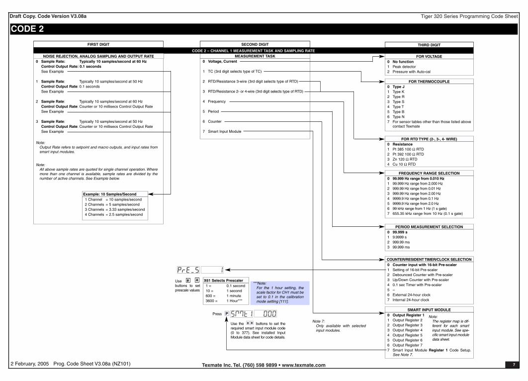
FOR VOLTAGE0 No function1 Peak detector2 Pressure with Auto-cal
FOR THERMOCOUPLE0 Type J1 Type K2 Type R3 Type S4 Type T5 Type B6 Type N7 For sensor tables other than those listed above
contact Texmate
FOR RTD TYPE (2-, 3-, 4- WIRE)0 Resistance1 Pt 385 100 Ω RTD2 Pt 392 100 Ω RTD3 Zn 120 Ω RTD4 Cu 10 Ω RTD
FREQUENCY RANGE SELECTION0 99.999 Hz range from 0.010 Hz1 99.999 Hz range from 2.000 Hz2 999.99 Hz range from 0.01 Hz3 999.99 Hz range from 2.00 Hz4 9999.9 Hz range from 0.1 Hz5 9999.9 Hz range from 2.0 Hz6 99 kHz range from 1 Hz (1 s gate)7 655.35 kHz range from 10 Hz (0.1 s gate)
PERIOD MEASUREMENT SELECTION0 99.999 s1 9.9999 s2 999.99 ms3 99.999 ms
COUNTER/RESIDENT TIMER/CLOCK SELECTION0 Counter input with 16-bit Pre-scaler1 Setting of 16-bit Pre-scaler2 Debounced Counter with Pre-scaler 3 Up/Down Counter with Pre-scaler4 0.1 sec Timer with Pre-scaler5 –6 External 24-hour clock7 Internal 24-hour clock
MEASUREMENT TASK0 Voltage, Current
1 TC (3rd digit selects type of TC)
2 RTD/Resistance 3-wire (3rd digit selects type of RTD)
3 RTD/Resistance 2- or 4-wire (3rd digit selects type of RTD)
4 Frequency
5 Period
6 Counter
7 Smart Input Module
CODE 2 – CHANNEL 1 MEASUREMENT TASK AND SAMPLING RATE
SMART INPUT MODULE0 Output Register 11 Output Register 22 Output Register 33 Output Register 44 Output Register 55 Output Register 66 Output Register 77 Smart Input Module Register 1 Code Setup.
See Note 7.
THIRD DIGITSECOND DIGIT
CODE 2
Note 7:Only available with selectedinput modules.
1 = 0.1 second10 = 1 second600 = 1 minute3600 = 1 Hour***
X61 Selects PrescalerUse buttons to setprescale values
Note:The register map is dif-ferent for each smartinput module. See spe-cific smart input moduledata sheet.
***Note:For the 1 hour setting, thescale factor for CH1 must beset to 0.1 in the calibrationmode setting [111].
PPress
Use the buttons to set therequired smart input module code(0 to 377). See installed InputModule data sheet for code details.
0 Sample Rate: Typically 10 samples/second at 60 HzControl Output Rate: 0.1 secondsSee Example
1 Sample Rate: Typically 10 samples/second at 50 HzControl Output Rate: 0.1 secondsSee Example
2 Sample Rate: Typically 10 samples/second at 60 HzControl Output Rate: Counter or 10 millisecs Control Output RateSee Example
3 Sample Rate: Typically 10 samples/second at 50 HzControl Output Rate: Counter or 10 millisecs Control Output RateSee Example
Note:Output Rate refers to setpoint and macro outputs, and input rates fromsmart input modules.
Note:All above sample rates are quoted for single channel operation. Wheremore than one channel is available, sample rates are divided by thenumber of active channels. See Example below.
1 Channel = 10 samples/second2 Channels = 5 samples/second3 Channels = 3.33 samples/second4 Channels = 2.5 samples/second
Example: 10 Samples/Second
NOISE REJECTION, ANALOG SAMPLING AND OUTPUT RATE
FIRST DIGIT

Tiger 320 Series Programming Code SheetDraft Copy. Code Version V3.08a
Texmate Inc. Tel. (760) 598 9899 • www.texmate.com 82 February, 2005 Prog. Code Sheet V3.08a (NZ101)
CODES 3 to 5FIRST DIGIT SECOND DIGIT THIRD DIGIT
CHANNEL 1 POST PROCESSING0 Direct Display of Input (no pro-
cessing)1 Square Root of Channel 12 Inverse of Channel 13 –
32-POINT LINEARIZATION FOR CHANNEL 10 No Linearization on CH11 32-point Linearization on CH1 using Table 12 32-point Linearization on CH1 using Table 2.
See Note 53 32-point Linearization on CH1 using Table 3.
See Note 54 32-point Linearization on CH1 using Table 4.
See Note 55 125-point Linearization on CH1 (Tables 1 to 4
cascaded). See Note 56 32-point Linearization on CH1 (Tables 1 to 4
selected from the rear pins of selected inputmodules).The selected table is not available if CH2, CH3,or CH4 is operating in the analog output mode.CH1 must be set to Voltage, Current in Code 2[X0X]. See Note 5
7 -
Note:All linearization tables are set up in theCalibration Mode [24X].
SERIAL MODE0 ASCII Mode1 Modbus Mode2 Macro master mode (used to cus-
tomize print mode protocols viamacro)
3 Print Mode4 Ethernet Mode. See Note 65 Devicenet Mode (requires
Devicenet hardware module).See Note 6
CODE 3 – CHANNEL 1 FUNCTIONS (POST PROCESSING & SERIAL MODE)
MEASUREMENT TASK0 Voltage, Current
1 TC (type as per 2nd digit)
2 RTD/Resistance(type as per 2nd digit)
3 Second Digital Input Channel(type as per 2nd digit)
FOR VOLTAGE & CURRENT0 Channel 2 Disabled1 Direct (no post processing)2 Square Root of Channel 23 Inverse of Channel 24 Output Register 1 (smart module)*5 Output Register 2 (smart module)*6 Output Register 3 (smart module)*7 Output Register 4 (smart module)*
32-POINT LINEARIZATION FOR CH20 No user defined Linearization
on CH21 32-point Linearization on CH2
using Table 12 32-point Linearization on CH2
using Table 2. See Note 53 32-point Linearization on CH2
using Table 3. See Note 54 32-point Linearization on CH2
using Table 4. See Note 55 125-point Linearization on CH2
(Tables 1 to 4 cascaded). SeeNote 5
6 –7 –
CODE 4 – CHANNEL 2 MEASUREMENT TASK AND 32-POINT LINEARIZATION
FOR THERMOCOUPLE0 Type J1 Type K2 Type R3 Type S4 Type T5 Type B6 Type N7 For sensor tables other than those list-
ed above contact Texmate
FOR RTD TYPE (3-WIRE)0 Resistance1 Pt 385 100 Ω RTD2 Pt 392 100 Ω RTD3 Zn 120 Ω RTD4 Cu 10 Ω RTD
DIGITAL INPUT0 Frequency - 99.999 Hz range from
0.001 Hz1 Frequency - 999.99 Hz range from 0.01 Hz2 Frequency - 99.999 kHz range from 1 Hz
(1 s gate)3 Frequency - 500 kHz range from 10 Hz
(0.1 s gate)4 Period - 9.9999 s (100 µs resolution)5 Period - 999.99 ms (10 µs resolution)6 Up/Down Counter with Prescaler7 Set Prescaler
FOR THERMOCOUPLE0 Type J1 Type K2 Type R3 Type S4 Type T5 Type B6 Type N7 For sensor tables other than those
listed above contact Texmate
FOR RTD TYPE (2-, 3-, 4- WIRE)0 Resistance1 Pt 385 100 Ω RTD2 Pt 392 100 Ω RTD3 Zn 120 Ω RTD4 Cu 10 Ω RTD
MEASUREMENT TASK0 No Function
1 Voltage, current
2 TC (3rd digit selects type of TC)
3 RTD/Resistance (3rd digit selects type of RTD)
4 Real Time Clock & Timer (3rd digit selects type)
5 -
6 -
7 Smart Input Module (3rd digit selects register)
CODE 5 – CHANNEL 3 FUNCTIONSFIRST DIGIT SECOND DIGIT THIRD DIGIT
CH3 POST PROCESSING0 Direct Display of Input
(no processing)1 Square Root of
Channel 32 Inverse of Channel 33 4 kilobits Meters
NO Linearization32 kilobits Meters32-point Linearizationof CH3 using Table 3
Note:All linearizationtables are set up inthe Calibration Mode[24X].
FOR REAL-TIME CLOCK & TIMER0 HRS:MIN:SEC1 HRS:MIN2 -3 -4 1 Second Count UP Timer5 1 Second Count DOWN Timer6 -7 -
FOR SMART INPUT MODULE0 Output Register 11 Output Register 22 Output Register 33 Output Register 44 Output Register 55 Output Register 66 Output Register 77 Smart Input Module Register 2
Code Setup
Note 6:These functions are not availableon all models and in some casesrequire additional hardware.
Note 5:If only 4 kilobits of memory isinstalled, only Table 1 is available for:
• CH1 in Code 3, 2nd digit.
• CH2 in Code 4, 3rd digit.
• CH3 in Code 5, 1st digit.
• CH4 in Code 6, 1st digit.
• RESULT in Code 7, 2nd digit.
Note:The function of the out-put register selectedvaries according to theinput module installed.
*Note:Selecting 040 to 070 in the 2nd digit of Code 4 selectsone of the following settings in the installed smart inputmodule’s output register map:
4 selects5 selects6 selects7 selects
Note:The register map is different for each smart inputmodule. See installed input module data sheet forspecific smart register 1 function map.
2nd Digit Input module’s output register map
0123
1 = 0.1 second10 = 1 second600 = 1 minute3600 = 1 Hour***
X61 Selects PrescalerUse buttons to setprescale values
***Note:For the 1 hour setting, thescale factor for CH1 must beset to 0.1 in the calibrationmode setting [111].
PPress
Use the buttons to set therequired smart input module code(0 to 377). See installed InputModule data sheet for code details.
Tiger 320 Series Programming Code SheetDraft Copy. Code Version V3.08a
Texmate Inc. Tel. (760) 598 9899 • www.texmate.com 92 February, 2005 Prog. Code Sheet V3.08a (NZ101)
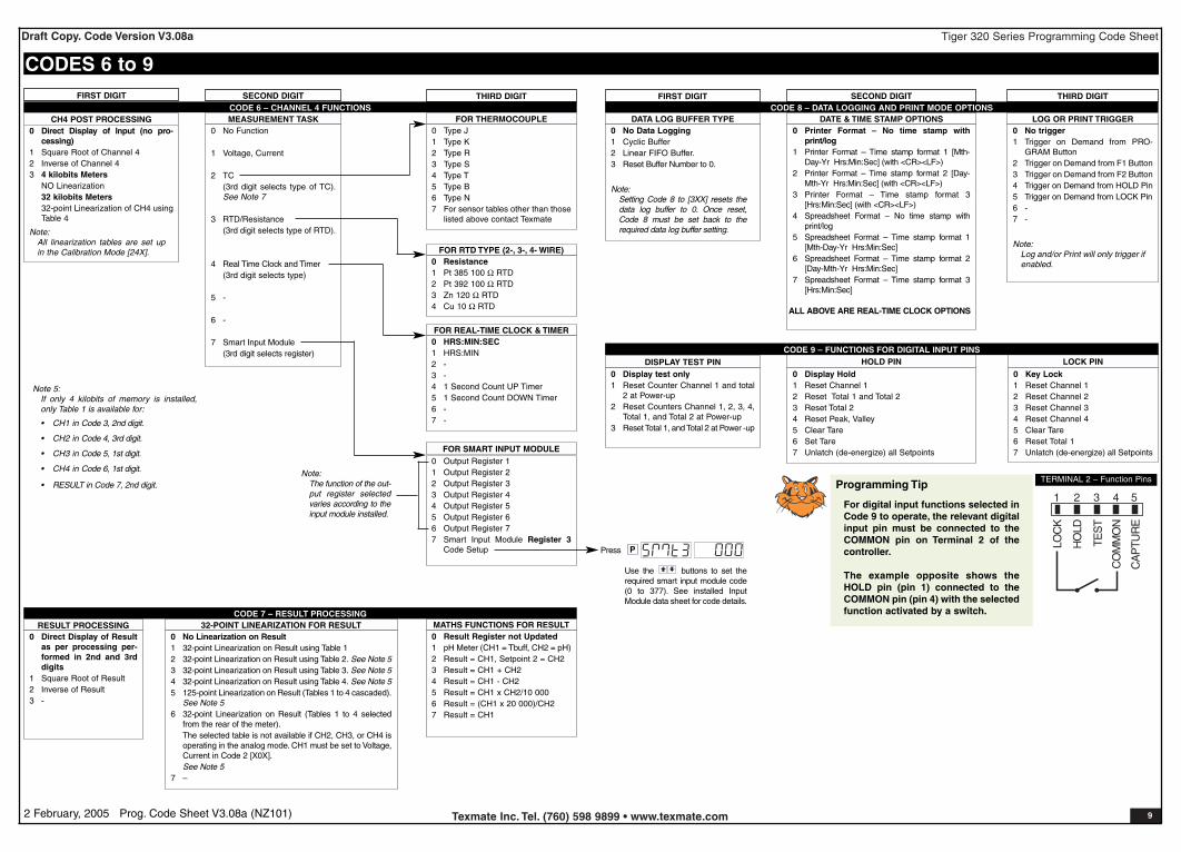
CODES 6 to 9
CH4 POST PROCESSING0 Direct Display of Input (no pro-
cessing)1 Square Root of Channel 42 Inverse of Channel 43 4 kilobits Meters
NO Linearization32 kilobits Meters32-point Linearization of CH4 usingTable 4
Note:All linearization tables are set upin the Calibration Mode [24X].
CODE 6 – CHANNEL 4 FUNCTIONSFIRST DIGIT SECOND DIGIT THIRD DIGIT
FOR THERMOCOUPLE0 Type J1 Type K2 Type R3 Type S4 Type T5 Type B6 Type N7 For sensor tables other than those
listed above contact Texmate
FOR RTD TYPE (2-, 3-, 4- WIRE)0 Resistance1 Pt 385 100 Ω RTD2 Pt 392 100 Ω RTD3 Zn 120 Ω RTD4 Cu 10 Ω RTD
MEASUREMENT TASK0 No Function
1 Voltage, Current
2 TC(3rd digit selects type of TC).See Note 7
3 RTD/Resistance(3rd digit selects type of RTD).
4 Real Time Clock and Timer(3rd digit selects type)
5 -
6 -
7 Smart Input Module(3rd digit selects register)
FOR SMART INPUT MODULE0 Output Register 11 Output Register 22 Output Register 33 Output Register 44 Output Register 55 Output Register 66 Output Register 77 Smart Input Module Register 3
Code Setup
RESULT PROCESSING0 Direct Display of Result
as per processing per-formed in 2nd and 3rddigits
1 Square Root of Result2 Inverse of Result3 -
32-POINT LINEARIZATION FOR RESULT0 No Linearization on Result1 32-point Linearization on Result using Table 12 32-point Linearization on Result using Table 2. See Note 53 32-point Linearization on Result using Table 3. See Note 54 32-point Linearization on Result using Table 4. See Note 55 125-point Linearization on Result (Tables 1 to 4 cascaded).
See Note 56 32-point Linearization on Result (Tables 1 to 4 selected
from the rear of the meter).The selected table is not available if CH2, CH3, or CH4 isoperating in the analog mode. CH1 must be set to Voltage,Current in Code 2 [X0X].See Note 5
7 –
MATHS FUNCTIONS FOR RESULT0 Result Register not Updated1 pH Meter (CH1 = Tbuff, CH2 = pH)2 Result = CH1, Setpoint 2 = CH23 Result = CH1 + CH24 Result = CH1 - CH25 Result = CH1 x CH2/10 0006 Result = (CH1 x 20 000)/CH27 Result = CH1
CODE 7 – RESULT PROCESSING
CODE 8 – DATA LOGGING AND PRINT MODE OPTIONSFIRST DIGIT SECOND DIGIT THIRD DIGIT
DATA LOG BUFFER TYPE0 No Data Logging1 Cyclic Buffer2 Linear FIFO Buffer.3 Reset Buffer Number to 0.
Note:Setting Code 8 to [3XX] resets thedata log buffer to 0. Once reset,Code 8 must be set back to therequired data log buffer setting.
DATE & TIME STAMP OPTIONS0 Printer Format – No time stamp with
print/log1 Printer Format – Time stamp format 1 [Mth-
Day-Yr Hrs:Min:Sec] (with <CR><LF>)2 Printer Format – Time stamp format 2 [Day-
Mth-Yr Hrs:Min:Sec] (with <CR><LF>)3 Printer Format – Time stamp format 3
[Hrs:Min:Sec] (with <CR><LF>)4 Spreadsheet Format – No time stamp with
print/log5 Spreadsheet Format – Time stamp format 1
[Mth-Day-Yr Hrs:Min:Sec]6 Spreadsheet Format – Time stamp format 2
[Day-Mth-Yr Hrs:Min:Sec]7 Spreadsheet Format – Time stamp format 3
[Hrs:Min:Sec]
ALL ABOVE ARE REAL-TIME CLOCK OPTIONS
LOG OR PRINT TRIGGER0 No trigger1 Trigger on Demand from PRO-
GRAM Button2 Trigger on Demand from F1 Button3 Trigger on Demand from F2 Button4 Trigger on Demand from HOLD Pin5 Trigger on Demand from LOCK Pin6 -7 -
Note:Log and/or Print will only trigger ifenabled.
DISPLAY TEST PIN0 Display test only1 Reset Counter Channel 1 and total
2 at Power-up2 Reset Counters Channel 1, 2, 3, 4,
Total 1, and Total 2 at Power-up3 Reset Total 1, and Total 2 at Power -up
HOLD PIN0 Display Hold1 Reset Channel 12 Reset Total 1 and Total 23 Reset Total 24 Reset Peak, Valley5 Clear Tare6 Set Tare7 Unlatch (de-energize) all Setpoints
LOCK PIN0 Key Lock1 Reset Channel 12 Reset Channel 23 Reset Channel 34 Reset Channel 45 Clear Tare6 Reset Total 17 Unlatch (de-energize) all Setpoints
CODE 9 – FUNCTIONS FOR DIGITAL INPUT PINS
FOR REAL-TIME CLOCK & TIMER0 HRS:MIN:SEC1 HRS:MIN2 -3 -4 1 Second Count UP Timer5 1 Second Count DOWN Timer6 -7 -
PPress
Note 5:If only 4 kilobits of memory is installed,only Table 1 is available for:
• CH1 in Code 3, 2nd digit.
• CH2 in Code 4, 3rd digit.
• CH3 in Code 5, 1st digit.
• CH4 in Code 6, 1st digit.
• RESULT in Code 7, 2nd digit.Note:
The function of the out-put register selectedvaries according to theinput module installed.
Use the buttons to set therequired smart input module code(0 to 377). See installed InputModule data sheet for code details.
21 3 4 5
LOC
K
HO
LD
TES
T
CO
MM
ON
CA
PTU
RE
TERMINAL 2 – Function PinsProgramming Tip
For digital input functions selected inCode 9 to operate, the relevant digitalinput pin must be connected to theCOMMON pin on Terminal 2 of thecontroller.
The example opposite shows theHOLD pin (pin 1) connected to theCOMMON pin (pin 4) with the selectedfunction activated by a switch.
Tiger 320 Series Programming Code SheetDraft Copy. Code Version V3.08a
Texmate Inc. Tel. (760) 598 9899 • www.texmate.com 102 February, 2005 Prog. Code Sheet V3.08a (NZ101)
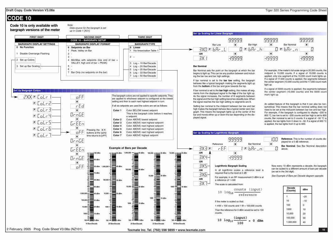
Logirithmic Bargraph Scaling
In all logirithmic scales a reference level isrequired that is the level at 0 dB.
For example, in an RF measurement 0 dBm is ata reference of 1 mW.
The scale is calculated from:
If the meter is scaled so that:
1 mW = 100 counts and 1 W = 100,000 counts
Then the reference for 0 dBm would be set to 100counts:
BARGRAPH DISPLAY SETTINGS0 No Function
1 Disable Overrange Flashing
2 Set up Colors
3 Set up Bar Scaling
BARGRAPH DISPLAY FORMAT BARGRAPH TYPE0 Linear1 Via linearization Table 1
2 –
3 Log – 10 Bar/Decade4 Log – 20 Bar/Decade5 Log – 25 Bar/Decade6 Log – 33 Bar/Decade7 Log – 50 Bar/Decade
CODE 10 – BARGRAPH SETUP
0 Setpoints on Bar1 Peak, Valley on Bar2 -3 -4 Min/Max with setpoints (low end of bar =
VALLEY, high end of bar = PEAK)5 -6 -7 Bar Only (no setpoints on the bar)
Code 10 is only available withbargraph versions of the meter
Note:Data source for the bargraph is setup in Code 1 [X51].
CODE 10
P
P
P
P
P
P
P
The bargraph colors are not applied to specific setpoints.Theyare applied to whichever setpoint is configured at the lowestsetting and then to each next highest setpoint in turn.
If all six setpoints are used the colors are set as follows:
Color 1 Color BELOW lowest setpointThis is the bargraph color before it reaches a setpoint.
Color 2 Color ABOVE lowest setpointColor 3 Color ABOVE next highest setpointColor 4 Color ABOVE next highest setpointColor 5 Color ABOVE next highest setpointColor 6 Color ABOVE next highest setpointColor 7 Color ABOVE highest setpoint
Set Up Bargraph Colors
P
Set Up Scaling for Linear Bargraph
OR
P P
Bar Low Bar High Bar Nominal
P
Set Up Scaling for Logirithmic Bargraph
OR
P
Reference Bar Nominal
OR
OR
OR
FIRST DIGIT SECOND DIGIT THIRD DIGIT
Pressing the buttons at the sametime returns to [oFF]
Bar Nominal
Bar Nominal sets the point on the bargraph at which the barbegins to light up.This can be any position between and includ-ing the bar low and bar high settings.
If bar nominal is set to the bar low setting, the bargraphbehaves like a typical bargraph making the segments light upfrom the bottom of the bar and grow towards the top.
If bar nominal is set to the bar high setting, this makes all seg-ments from the displayed signal to the top of the bar light up.As the signal increases, the number of lit segments betweenthe signal and the bar high setting becomes steadily less.Whenthe signal reaches the bar high setting no segments are lit.
Setting bar nominal to the midpoint between bar low and barhigh makes the bargraph behave like a typical center zero bar-graph. This means the bargraph lights up at the center of thebar and moves either up or down the bar depending on the dis-played signal.
An added feature of this bargraph is that it can also be non-symetrical. This means that the bar nominal setting does notneed to be set at the mid-point between bar low and bar high.For example, if the bargraph is configured to display –200 to800 °C, bar low is set to –200 counts and bar high is set to 800counts. Bar nominal is set to 0 counts. If a signal of –50 °C isapplied, the bar lights from 0 down to –50. If a signal of 600 °Cis applied, the bar lights from 0 up to 600.
For example, if the meter's full scale range is 20,000 counts, themidpoint is 10,000 counts. If a signal of 10,000 counts isapplied, only one segment at the 10,000 count mark lights up.If a signal of 17,000 counts is applied, the segments betweenthe center segment (10,000 counts) and the 17,000 count marklight up.
If a signal of 5000 counts is applied, the segments betweenthe center segment (10,000 counts) and the 5000 countmark light up.
10 log10(input)
100= 0 dBm
Decade(Counts)
–20
–10
0
10
20
30
40
1
10
100
1000
10,000
100,000
1,000,000
Now every 10 dBm represents a decade, the bargraphcan be scaled to a different amount of bars per decade(as set in the 3rd digit).
See Example of Bars per Decade diagram opposite.
dBm
Reference. This is the number of counts dis-played for a 0 dB reference.
Bar Nominal. See Bar Nominal descriptionabove.
100 dBm
80 dBm
60 dBm
40 dBm
20 dBm
0 dBm
10 Bars/Decade
90 dBm
70 dBm
50 dBm
30 dBm
10 dBm
40 dBm
20 dBm
0 dBm
20 Bars/Decade
50 dBm
30 dBm
10 dBm
40 dBm
0 dBm
25 Bars/Decade
30 dBm
20 dBm
10 dBm
0 dBm
33 Bars/Decade
30 dBm
20 dBm
10 dBm
0 dBm
50 Bars/Decade
20 dBm
10 dBm
100
1000
10,000
100,000
1,000,000
100
1000
10,000
100,000
1,000,000
100
1000
10,000
100,000
1,000,000
100
1000
10,000
100,000
100
1000
10,000
Example of Bars per Decade
10 log10counts (input)
reference

Tiger 320 Series Programming Code SheetDraft Copy. Code Version V3.08a
Texmate Inc. Tel. (760) 598 9899 • www.texmate.com 112 February, 2005 Prog. Code Sheet V3.08a (NZ101)
Follow These StepsThe following procedures are written for SP1, all other setpoints are con-figured in a similar manner.
1) Press the and buttons at the same time.This enters the set-point programming mode.The display toggles between [SP_1] and[18000].
This is SP1 of the Setpoint Activation Values Mode. Use the and buttons to set SP1 or the button to move to the requiredsetpoint.
2) After all required setpoint activation values have been set, pressthe button until [SPC_1] appears.This is the Setpoint & RelayControl Settings Mode.
SPC_1 is the setpoint and relay control settings programmingmenu for SP1. Set the three digits according to the codes in theSetpoint and Relay Control Function Settings opposite in the fol-lowing order:
Third Digit – Setpoint Delay Mode
Set to [XX5] and program the hysteresis, deviation, or PIDfunctions as required for SP1.
Reset back to [XX0].
Third Digit – Setpoint Timer Mode
Set to [XX6] and program the timer mode functions asrequired for SP1.
Reset back to [XX0].
Third Digit – Setpoint Reset & Trigger Functions
Set to [XX7] and program the reset and trigger functions asrequired for SP1.
Reset back to [XX0].
Second Digit – Setpoint Activation Source Mode
Set to [X1X] to select the setpoint activation source for SP1from any channel or selected register shown above. Resetback to [X0X].
If the SP source is from an external digital input, set to one ofeither [X2X] to [X7X] to select the setpoint activation sourcefrom one of six digital inputs (2 to 7). See *Note at 2nd digit.
First Digit – Relay Energize Mode
Select the relay energize mode for SP1 from 0 to 3.
Third Digit – Relay Latching & Manual Reset Functions
Program the third digit setpoint relay latching and manualreset functions between 0 to 4 as required.
3) Press the button to move to move to [SPC_2].
4) Repeat Step 2 for all required setpoints.
P
P
P
P
Setpoint Setup Sequence
0 No Latching1 Relay Latched2 Manual Relay Reset3 Relay Latched and Manual Relay
Reset4 Relay Latched Off
5 Hysteresis, Deviation & PID Mode(includes SP Tracking)
6 Timer Modes:•OFF.•Normal Delay.•Repeat ON.•Pulse ON.•1-Shot ON.•Repeat OFF.•Pulse OFF.•1-Shot OFF.
Note:In PID Mode, all Timer Modes onSP1 set in [XX6 are not functional.
7 Advanced Functions Mode:•OFF.•Reset Trigger.•Reset Destination.•Reset Mode.•Reset Constant.•Trigger Print from SP.•Trigger Log from SP.
Note:[XX5], [XX6], and [XX7] are set upprocedures only. To finish, reset to0-4 as required for setpoint latchingand relay reset modes.
SETPOINT PROGRAMMING MODE – SPC_1 to SPC_6
Relay Energize Function SP Activation Source0 Activate Setpoint Source from
Selected Register
1 Select Source for Setpoint
Note:[X1X] is a register selection procedureonly. To finish, reset to [X0X] to activatethe selection, or reset to 2-7 as requiredfor digital input selection.
2 Digital Input – Capture Pin3 Digital Input – D1 (selected input modules)4 Digital Input – D2 (selected input modules)5 Digital Input – D3 (selected input modules)6 HOLD Pin7 LOCK Pin
*Note:If the setpoint source is set to [oFF] or adigital input, the setpoint activation valuewill have no effect and will not be dis-played.
SP Functions
FIRST DIGIT SECOND DIGIT THIRD DIGITSETPOINT AND RELAY CONTROL FUNCTION SETTINGS
Select Source for Setpoint Functions
Go toPage 12
Go toPage 12
Go toPage 13
[TOT_1] [TOT_2] [TARE]
[RESULT]
[CH1]
[CH2]
[CH3] [CH4]
[DISP]
[ 1] [ 2] .....[ 10] [ 11] [ 12] .....[ 20] [ 100][ 200]
.....[ 239]The button takes you forward, the button takes you back.
[AUX_5]
[VALLEY][PEAK]
[AUX_4]
[AUX_3]
[AUX_2]
[AUX_1]
Constant pressure on the button moves thru Registers 1 to 239one register at a time until you get to ten, then it jumps in multiplesof 10, until you reach 100, then it jumps in multiples of 100.
Stopping and starting again resumes single steps forward.
Use the andbuttons to cycle throughthe Registers Menu andRegisters (1 to 239) toselect the data sourcefor displays, peak andvalley, totalizers andanalog output.
0 Relay energizes ABOVE setpoint value
1 Relay energizes BELOW setpoint value
2 Relay energizes AT OR ABOVE setpoint value with FALLING INPUTSIGNAL INITIAL START-UP INHIBIT
3 Relay energizes BELOW setpoint value with RISING INPUT SIGNALINITIAL START-UP INHIBIT
See Page 14 for a detailed description of the relay energize options.

Tiger 320 Series Programming Code SheetDraft Copy. Code Version V3.08a
Texmate Inc. Tel. (760) 598 9899 • www.texmate.com 122 February, 2005 Prog. Code Sheet V3.08a (NZ101)
PXXP PP XX XX
P PP XX
P P PP XX
P P PP XX
P PP XX
P P PP XX
P P PP XX
P
P
P
Set Deviation from 1 to65535 counts. Selectedcounts apply + and – fromsetpoint value
P P P P P P
Set the Span Set the Proportional Band Value Set the Integral Value Set the Derivative Value Set the Anti-reset Wind-up % PB Set the Minimum Cycle Time
PID FROM SETPOINT1 AND 2 ONLY
MIN 0%
MAX 999.9%
MIN 0
MAX 99999
MIN 0
MAX 6553.5
MIN 0
MAX 999.9
MIN 0.1%
MAX 100.0%
MIN 0 secs
MAX 1000.0 secs
Select Tracking Setting
to
P
Select Flash Setting OFF or ON
P
OFF= Tracking Off1 = SPX tracks SP12 = SPX tracks SP23 = SPX tracks SP34 = SPX tracks SP45 = SPX tracks SP56 = SPX tracks SP6
Set Hysteresis from 0 to65535 counts. Selectedcounts apply + and – fromsetpoint value
Select Tracking Setting
to
P
From Page11, 3rd digit[XX5]
From Page 11,3rd digit [XX6]
Delay-on-make time (DOM)0.1 to 6553.5 secs
Delay-on-break (DOB) time0.1 to 6553.5 secs
Reset SPC_X to XX0
DOM 0.1 to 6553.5 secs Minimum on-time (M_on)0.1 to 6553.5 secs
On-time (on_t) 0.1/0.001to 6553.5/65.535 secs
DOM 0.1/0.001 to6553.5/65.535 secs
On-time (on_t) 0.1/0.001 to6553.5/65.535 secs
DOB 0.1 to 6553.5 secs
Off-time (oFF_t) 0.1/0.001 to6553.5/65.535 secs
DOB 0.1/0.001 to 6553.5/65.535 secs
On_t 0.1/0.001 to 6553.5/65.535 secs
Off-time (oFF_t) 0.1/0.001to 6553.5/65.535 secs
Off-time (oFF_t) 0.1/0.001to 6553.5/65.535 secs
Minimum off-time (M_of)0.1 to 6553.5 secs
Set Up Hysteresis, Deviation & PID Mode Settings
Set Up Timer Delay Settings
XXP XXReset SPC_X to XX0
Programming Tip
If you do not require anyof the functions in thismode, ensure it is set to:
Programming Tip
If you do not require anyof the functions in thismode, ensure it is set to:
Note:If PID is selected in [XX5],the Timer Delay [XX6] andReset and Trigger Functions[XX7] revert to [ModE][oFF]and cannot be adjusted.
Normal Mode
1-Shot ON Mode
Pulse ON Mode
Repeat ON Mode
1-Shot OFF Mode
Pulse OFF Mode
Repeat OFF Mode
Normally OFF/Pulsed ON ModesThese are time control modes were the relay isnormally OFF (de-energizes) and pulses ON(energizes) when the setpoint activates.
Normally ON/Pulsed OFF ModesThese are time control modes were the relay isnormally ON (energizes) and pulses OFF (de-energizes) when the setpoint activates.
Resolution settingapplies to SP1/SP2ONLY
Resolution settingapplies to SP1/SP2ONLY
Resolution settingapplies to SP1/SP2ONLY
Resolution settingapplies to SP1/SP2ONLY
Note:If minimum cycle time is set to 0, the relevantrelay is disabled. PID functions still operate
Set to 0 for PID 4-20 mASet to MINIMUM 0.5 for SSRSet to 20 secs for Relays
Single Actuation
Single Actuation
Single Actuation
Single Actuation
Multiple Actuation
Multiple Actuation
Single Actuation
Tiger 320 Series Programming Code SheetDraft Copy. Code Version V3.08a
Texmate Inc. Tel. (760) 598 9899 • www.texmate.com 132 February, 2005 Prog. Code Sheet V3.08a (NZ101)
P
[diSP]
[rESLt]
[Ch1]
[Ch2]
[Ch3]
[Ch4]
[tot_1]
[tot_2]
[PEAK]
[VALEY]
[tArE]
[1 to 244]
P
P P
Use the buttons to cyclethrough the menu
[brEAK]
[both]
[LEVEL]
Sets from 0 to –19999
[i-S+C]
[d+C]
[rEG]
Sets from 0 to 99999
Select Reset Destination Register
Select Reset Trigger
Select Reset Mode Select Reset Constant
P
Select Print Triggered by Setpoint
P
Select Log Triggered by Setpoint
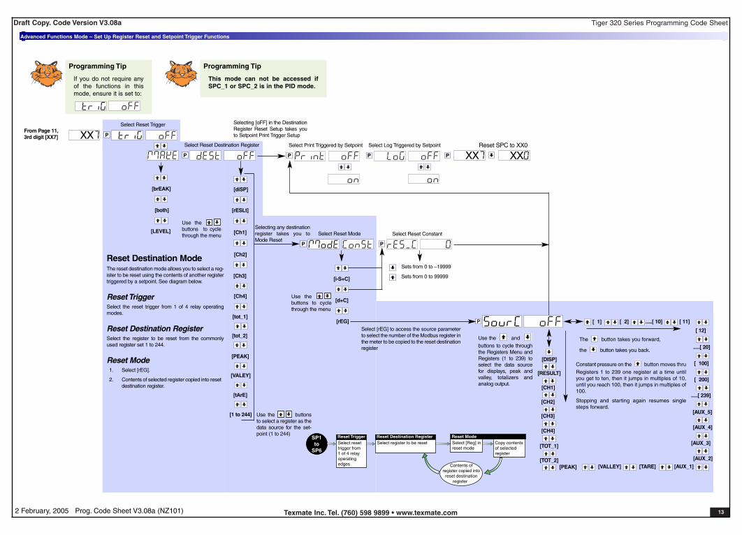
Advanced Functions Mode – Set Up Register Reset and Setpoint Trigger Functions
From Page 11,3rd digit [XX7]
Selecting any destinationregister takes you toMode Reset
Selecting [oFF] in the DestinationRegister Reset Setup takes youto Setpoint Print Trigger Setup
Select [rEG] to access the source parameterto select the number of the Modbus register inthe meter to be copied to the reset destinationregister
XXP XXReset SPC to XX0
XX
Use the buttons to cyclethrough the menu
Programming Tip
If you do not require anyof the functions in thismode, ensure it is set to:
Use the buttonsto select a register as thedata source for the set-point (1 to 244)
Programming Tip
This mode can not be accessed ifSPC_1 or SPC_2 is in the PID mode.
Select reset trigger from1 of 4 relayoperatingedges
Reset TriggerSelect register to be resetReset Destination Register
Select [Reg] inreset mode
Reset ModeCopy contentsof selectedregister
SP1to
SP6
Contents ofregister copied intoreset destination
register
Reset Destination ModeThe reset destination mode allows you to select a reg-ister to be reset using the contents of another registertriggered by a setpoint. See diagram below.
Reset TriggerSelect the reset trigger from 1 of 4 relay operatingmodes.
Reset Destination RegisterSelect the register to be reset from the commonlyused register set 1 to 244.
Reset Mode1. Select [rEG].
2. Contents of selected register copied into resetdestination register.
[TOT_1]
[TOT_2][TARE]
[RESULT]
[CH1]
[CH2]
[CH3]
[CH4]
[DISP]
[ 1] [ 2] .....[ 10] [ 11]
[ 12]
.....[ 20]
[ 100]
[ 200]
.....[ 239]
The button takes you forward,
the button takes you back.
[AUX_5]
[VALLEY][PEAK]
[AUX_4]
[AUX_3]
[AUX_2]
[AUX_1]
Constant pressure on the button moves thruRegisters 1 to 239 one register at a time untilyou get to ten, then it jumps in multiples of 10,until you reach 100, then it jumps in multiples of100.
Stopping and starting again resumes singlesteps forward.
Use the andbuttons to cycle throughthe Registers Menu andRegisters (1 to 239) toselect the data sourcefor displays, peak andvalley, totalizers andanalog output.
Tiger 320 Series Programming Code SheetDraft Copy. Code Version V3.08a
Texmate Inc. Tel. (760) 598 9899 • www.texmate.com 142 February, 2005 Prog. Code Sheet V3.08a (NZ101)
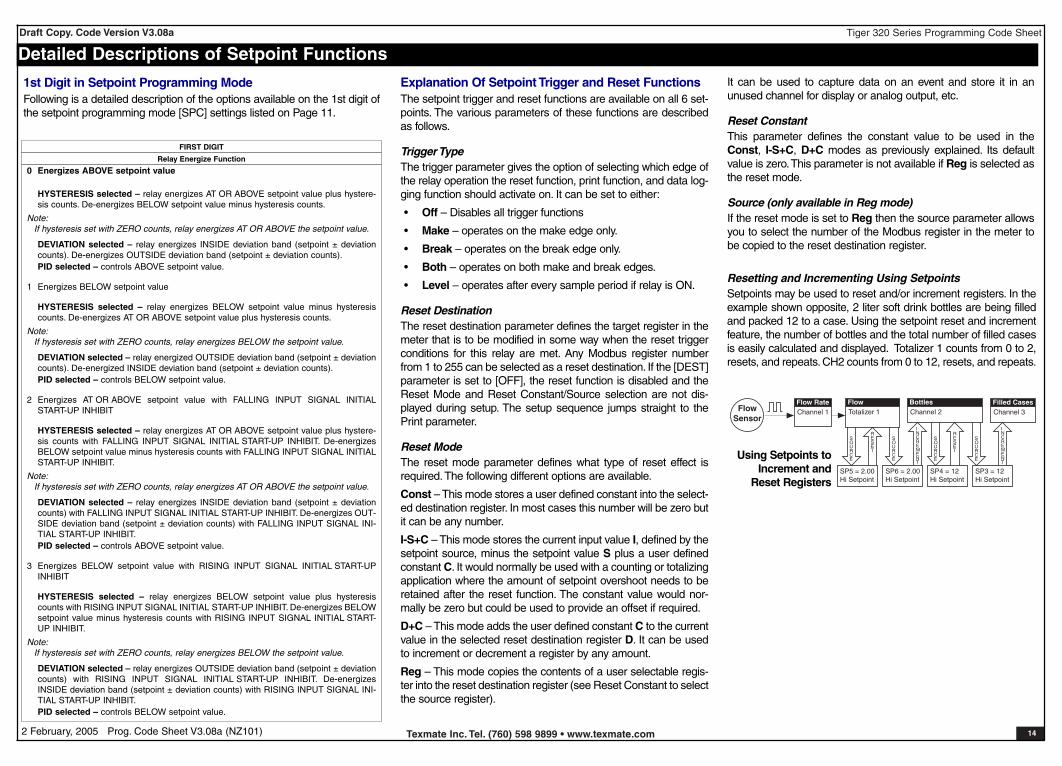
0 Energizes ABOVE setpoint value
HYSTERESIS selected – relay energizes AT OR ABOVE setpoint value plus hystere-sis counts. De-energizes BELOW setpoint value minus hysteresis counts.
Note:If hysteresis set with ZERO counts, relay energizes AT OR ABOVE the setpoint value.
DEVIATION selected – relay energizes INSIDE deviation band (setpoint ± deviationcounts). De-energizes OUTSIDE deviation band (setpoint ± deviation counts).PID selected – controls ABOVE setpoint value.
1 Energizes BELOW setpoint value
HYSTERESIS selected – relay energizes BELOW setpoint value minus hysteresiscounts. De-energizes AT OR ABOVE setpoint value plus hysteresis counts.
Note:If hysteresis set with ZERO counts, relay energizes BELOW the setpoint value.
DEVIATION selected – relay energized OUTSIDE deviation band (setpoint ± deviationcounts). De-energized INSIDE deviation band (setpoint ± deviation counts).PID selected – controls BELOW setpoint value.
2 Energizes AT OR ABOVE setpoint value with FALLING INPUT SIGNAL INITIALSTART-UP INHIBIT
HYSTERESIS selected – relay energizes AT OR ABOVE setpoint value plus hystere-sis counts with FALLING INPUT SIGNAL INITIAL START-UP INHIBIT. De-energizesBELOW setpoint value minus hysteresis counts with FALLING INPUT SIGNAL INITIALSTART-UP INHIBIT.
Note:If hysteresis set with ZERO counts, relay energizes AT OR ABOVE the setpoint value.
DEVIATION selected – relay energizes INSIDE deviation band (setpoint ± deviationcounts) with FALLING INPUT SIGNAL INITIAL START-UP INHIBIT. De-energizes OUT-SIDE deviation band (setpoint ± deviation counts) with FALLING INPUT SIGNAL INI-TIAL START-UP INHIBIT.PID selected – controls ABOVE setpoint value.
3 Energizes BELOW setpoint value with RISING INPUT SIGNAL INITIAL START-UPINHIBIT
HYSTERESIS selected – relay energizes BELOW setpoint value plus hysteresiscounts with RISING INPUT SIGNAL INITIAL START-UP INHIBIT. De-energizes BELOWsetpoint value minus hysteresis counts with RISING INPUT SIGNAL INITIAL START-UP INHIBIT.
Note:If hysteresis set with ZERO counts, relay energizes BELOW the setpoint value.
DEVIATION selected – relay energizes OUTSIDE deviation band (setpoint ± deviationcounts) with RISING INPUT SIGNAL INITIAL START-UP INHIBIT. De-energizesINSIDE deviation band (setpoint ± deviation counts) with RISING INPUT SIGNAL INI-TIAL START-UP INHIBIT.PID selected – controls BELOW setpoint value.
Resetting and Incrementing Using SetpointsSetpoints may be used to reset and/or increment registers. In theexample shown opposite, 2 liter soft drink bottles are being filledand packed 12 to a case. Using the setpoint reset and incrementfeature, the number of bottles and the total number of filled casesis easily calculated and displayed. Totalizer 1 counts from 0 to 2,resets, and repeats. CH2 counts from 0 to 12, resets, and repeats.
FlowSensor
Channel 1Flow Rate
Channel 3Filled Cases
Totalizer 1Flow
Channel 2Bottles
SP5 = 2.00Hi Setpoint
SP6 = 2.00Hi Setpoint
SP4 = 12Hi Setpoint
SP3 = 12Hi Setpoint
SOURCE
RESET
RESET
INCREMENT
INCREMENT
SOURCE
SOURCE
SOURCEUsing Setpoints to
Increment andReset Registers
Detailed Descriptions of Setpoint Functions
Explanation Of Setpoint Trigger and Reset FunctionsThe setpoint trigger and reset functions are available on all 6 set-points. The various parameters of these functions are describedas follows.
Trigger TypeThe trigger parameter gives the option of selecting which edge ofthe relay operation the reset function, print function, and data log-ging function should activate on. It can be set to either:
• Off – Disables all trigger functions
• Make – operates on the make edge only.
• Break – operates on the break edge only.
• Both – operates on both make and break edges.
• Level – operates after every sample period if relay is ON.
Reset DestinationThe reset destination parameter defines the target register in themeter that is to be modified in some way when the reset triggerconditions for this relay are met. Any Modbus register numberfrom 1 to 255 can be selected as a reset destination. If the [DEST]parameter is set to [OFF], the reset function is disabled and theReset Mode and Reset Constant/Source selection are not dis-played during setup. The setup sequence jumps straight to thePrint parameter.
Reset ModeThe reset mode parameter defines what type of reset effect isrequired. The following different options are available.
Const – This mode stores a user defined constant into the select-ed destination register. In most cases this number will be zero butit can be any number.
I-S+C – This mode stores the current input value I, defined by thesetpoint source, minus the setpoint value S plus a user definedconstant C. It would normally be used with a counting or totalizingapplication where the amount of setpoint overshoot needs to beretained after the reset function. The constant value would nor-mally be zero but could be used to provide an offset if required.
D+C – This mode adds the user defined constant C to the currentvalue in the selected reset destination register D. It can be usedto increment or decrement a register by any amount.
Reg – This mode copies the contents of a user selectable regis-ter into the reset destination register (see Reset Constant to selectthe source register).
1st Digit in Setpoint Programming ModeFollowing is a detailed description of the options available on the 1st digit ofthe setpoint programming mode [SPC] settings listed on Page 11.
Relay Energize Function
FIRST DIGIT
It can be used to capture data on an event and store it in anunused channel for display or analog output, etc.
Reset ConstantThis parameter defines the constant value to be used in theConst, I-S+C, D+C modes as previously explained. Its defaultvalue is zero.This parameter is not available if Reg is selected asthe reset mode.
Source (only available in Reg mode)If the reset mode is set to Reg then the source parameter allowsyou to select the number of the Modbus register in the meter tobe copied to the reset destination register.

Tiger 320 Series Programming Code SheetDraft Copy. Code Version V3.08a
Texmate Inc. Tel. (760) 598 9899 • www.texmate.com 152 February, 2005 Prog. Code Sheet V3.08a (NZ101)
Customer Code Settings – Main Programming Mode
1st DIGIT 2nd DIGIT 3rd DIGIT
CALIBRATION MODE [CAL]
020 SPAN
SUB-SETTINGS
030 ZERO SPAN
040 CHANNEL
050 CHANNEL
100 OFFSET SCALE
110 ZERO SPAN
121 ZERO SPAN
151 CAL LOW CAL HIGH
010
ON DEMAND FUNCTIONS
INPUT
INPUT INPUT
RESULT
021 SPAN
031 ZERO SPAN
041 CHANNEL
051 CHANNEL
011
INPUT
INPUT INPUT
CH1
022 SPAN
032 ZERO SPAN
042 CHANNEL
052 CHANNEL
012
INPUT
INPUT INPUT
CH2
023 SPAN
033 ZERO SPAN
043 CHANNEL
053 CHANNEL
013
INPUT
INPUT INPUT
CH3
024 SPAN
034 ZERO SPAN
044 CHANNEL
054 CHANNEL
014
INPUT
INPUT INPUT
CH4
1st DIGIT 2nd DIGIT 3rd DIGIT SUB-SETTINGS
CALIBRATION PROCEDURES
101 OFFSET SCALE
102 OFFSET SCALE
103 OFFSET SCALE
104 OFFSET SCALE
Manual Calibration
Two-point Calibration
INPUTINPUT
111 ZERO SPAN INPUTINPUT
112 ZERO SPAN INPUTINPUT
113 ZERO SPAN INPUTINPUT
114 ZERO SPAN INPUTINPUT
INPUT 32°F INPUT 2500°FCalibrate Thermocouple
122 ZERO SPANINPUT 32°F INPUT 2500°F
123 ZERO SPANINPUT 32°F INPUT 2500°F
OUTPUT OUTPUT
Calibrate Analog Output
152 CAL LOW CAL HIGHOUTPUT OUTPUT

Tiger 320 Series Programming Code SheetDraft Copy. Code Version V3.08a
Texmate Inc. Tel. (760) 598 9899 • www.texmate.com 162 February, 2005 Prog. Code Sheet V3.08a (NZ101)
200 BAUD PARITY ADDRESS TIME DELAY
1st DIGIT 2nd DIGIT 3rd DIGIT
CALIBRATION MODE [CAL] Continued
SUB-SETTINGS
RELATED CALIBRATION FUNCTIONS
201 BAUD PARITY ADDRESS TIME DELAY
202 BAUD PARITY ADDRESS TIME DELAY
203 BAUD PARITY ADDRESS TIME DELAY
204 BAUD PARITY ADDRESS TIME DELAY
Serial Output
Auto Zero Maintenance
210 AZ CAPTURE AZ MOTION AZ APERTURE
211 AZ CAPTURE AZ MOTION AZ APERTURE
212 AZ CAPTURE AZ MOTION AZ APERTURE
213 AZ CAPTURE AZ MOTION AZ APERTURE
214 AZ CAPTURE AZ MOTION AZ APERTURE
Averaging Samples & Averaging Window
220 AVERAGE SAMPLES AVERAGE WINDOW
231 SCALE FACTOR CUTOFF
240 MODE
251 ZERO FULL SCALE
221 AVERAGE SAMPLES AVERAGE WINDOW
222 AVERAGE SAMPLES AVERAGE WINDOW
223 AVERAGE SAMPLES AVERAGE WINDOW
224 AVERAGE SAMPLES AVERAGE WINDOW
K Factor & Totalizer Cutoff
232 SCALE FACTOR CUTOFF
32-point Linearization Tables
241 MODE
242 MODE
243 MODE
244 MODE
Scale Analog Output
252 ZERO FULL SCALE
Tiger 320 Series Programming Code SheetDraft Copy. Code Version V3.08a
Texmate Inc. Tel. (760) 598 9899 • www.texmate.com 172 February, 2005 Prog. Code Sheet V3.08a (NZ101)
1st DIGIT 2nd DIGIT 3rd DIGIT
CODE 1
X52
X53
X54
X55
X56
X57
X60 DISPLAY
X63
X65
X66
X67
X64
X50
X51
X62
X61
SOURCE
SOURCE
SOURCE
SOURCE
SOURCE
SOURCE
SOURCE
SOURCE
DISPLAY
DISPLAY
DISPLAY
DISPLAY
DISPLAY
DISPLAY
DISPLAY
X72
X73
X74
X75
X76
X77
X70
X71
CHARACTER
CHARACTER
CHARACTER
CHARACTER
CHARACTER
CHARACTER
CHARACTER
CHARACTER
1st DIGIT 2nd DIGIT 3rd DIGIT
CODE 2
PRESCALER
1st DIGIT 2nd DIGIT 3rd DIGIT
CODE 3
1st DIGIT 2nd DIGIT 3rd DIGIT
CODE 4
PRESCALER
1st DIGIT 2nd DIGIT 3rd DIGIT
CODE 5
SMART INPUT MODULESETTINGS
1st DIGIT 2nd DIGIT 3rd DIGIT
CODE 6
SMART INPUT MODULESETTINGS
1st DIGIT 2nd DIGIT 3rd DIGIT
CODE 7
1st DIGIT 2nd DIGIT 3rd DIGIT
CODE 8
1st DIGIT 2nd DIGIT 3rd DIGIT
CODE 9
SUB-SETTINGS 1st DIGIT 2nd DIGIT 3rd DIGIT
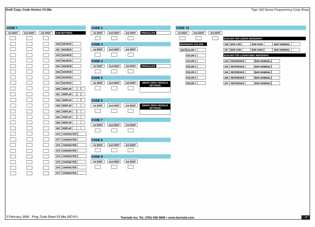
CODE 10
2XX COLOR 1
BARGRAPH COLORS
COLOR 2
COLOR 3
COLOR 4
COLOR 5
COLOR 6
COLOR 7
SCALING FOR LINEAR BARGRAPH
3X0 BAR LOW BAR HIGH BAR NOMINAL
3X1 BAR LOW BAR HIGH BAR NOMINAL
SCALING FOR LOGIRITHMIC BARGRAPH
3X3 REFERENCE BAR NOMINAL
3X4 REFERENCE BAR NOMINAL
3X5 REFERENCE BAR NOMINAL
3X6 REFERENCE BAR NOMINAL
3X7 REFERENCE BAR NOMINAL

Tiger 320 Series Programming Code SheetDraft Copy. Code Version V3.08a
Texmate Inc. Tel. (760) 598 9899 • www.texmate.com 182 February, 2005 Prog. Code Sheet V3.08a (NZ101)
Customer Code Settings – Setpoint Programming Mode
1st DIGIT 2nd DIGIT 3rd DIGIT
SP ACTIVATION VALUES
SETPOINT VALUE
SP1
SP2
SP3
SP4
SP5
SP6
SETPOINT & RELAY CONTROL SETTINGS MODE SPC_1 TO SPC_6
SELECT DATA SOURCE
SPC_1 _ 1 _
SPC_2
SPC_3
SPC_4
SPC_5
SPC_6
_ 1 _
_ 1 _
_ 1 _
_ 1 _
_ 1 _
DELAY MODE SETTINGS
SPC_1 _ _ 5
SPC_2
SPC_3
SPC_4
SPC_5
SPC_6
HYSTERESIS
_ _ 5
_ _ 5
_ _ 5
_ _ 5
_ _ 5
HYSTERESIS
HYSTERESIS
HYSTERESIS
HYSTERESIS
HYSTERESIS
ANNUNCIATOR FLASHING SP TRACKING
ANNUNCIATOR FLASHING SP TRACKING
ANNUNCIATOR FLASHING SP TRACKING
ANNUNCIATOR FLASHING SP TRACKING
ANNUNCIATOR FLASHING SP TRACKING
ANNUNCIATOR FLASHING SP TRACKING
DEVIATION ANNUNCIATOR FLASHING SP TRACKING
ANNUNCIATOR FLASHING SP TRACKING
ANNUNCIATOR FLASHING SP TRACKING
ANNUNCIATOR FLASHING SP TRACKING
ANNUNCIATOR FLASHING SP TRACKING
ANNUNCIATOR FLASHING SP TRACKING
DEVIATION
DEVIATION
DEVIATION
DEVIATION
DEVIATION
SPC_1 _ _ 5
SPC_2
SPC_3
SPC_4
SPC_5
SPC_6
SPAN
_ _ 5
_ _ 5
_ _ 5
_ _ 5
_ _ 5
PB
PID CONTROL SETTINGS
INT DER ARW MCT SP TRACKING
SPAN PB INT DER ARW MCT SP TRACKING
SPAN PB INT DER ARW MCT SP TRACKING
SPAN PB INT DER ARW MCT SP TRACKING
SPAN PB INT DER ARW MCT SP TRACKING
SPAN PB INT DER ARW MCT SP TRACKING
TIMER MODE SETTINGS
SPC_1 _ _ 6
SPC_2
SPC_3
SPC_4
SPC_5
SPC_6
_ _ 6
_ _ 6
_ _ 6
_ _ 6
_ _ 6
SPC SETTINGNORMALLY OFF / PULSED ON MODES
REPEAT ON
Resolution
NORMAL
DOM
DOB
DOM
DOB
DOM
DOB
DOM
DOB
DOM
DOB
DOM
DOB
Resolution
Resolution
Resolution
Resolution
Resolution
OFF T
ON T
OFF T
ON T
OFF T
ON T
OFF T
ON T
OFF T
ON T
OFF T
ON T
1-SHOT ON
DOM
M ON
DOM
M ON
DOM
M ON
DOM
M ON
DOM
M ON
DOM
M ON
PULSE ON
Resolution
Resolution
Resolution
Resolution
Resolution
Resolution
DOM
ON_T
DOM
ON T
DOM
ON T
DOM
ON T
DOM
ON T
DOM
ON T
1-SHOT OFF
M OFF
DOB
M OFF
DOB
M OFF
DOB
M OFF
DOB
M OFF
DOB
M OFF
DOB
NORMALLY ON / PULSED OFF MODES
PULSE OFF
Resolution
Resolution
Resolution
Resolution
Resolution
Resolution
OFF T
DOB
OFF T
DOB
OFF T
DOB
OFF T
DOB
OFF T
DOB
OFF T
DOB
REPEAT OFF
Resolution
Resolution
Resolution
Resolution
Resolution
Resolution
OFF T
ON T
OFF T
ON T
OFF T
ON T
OFF T
ON T
OFF T
ON T
OFF T
ON T
SPC_1 _ _ 7
SPC_2
SPC_3
SPC_4
SPC_5
SPC_6
[triG]
_ _ 7
_ _ 7
_ _ 7
_ _ 7
_ _ 7
[dESt]
REGISTER RESET & TRIGGER FUNCTIONS SETTINGS
[ModE] [rES_C] [SourC] [Print] [LoG]
[triG] [dESt] [ModE] [rES_C] [SourC] [Print] [LoG]
[triG] [dESt] [ModE] [rES_C] [SourC] [Print] [LoG]
[triG] [dESt] [ModE] [rES_C] [SourC] [Print] [LoG]
[triG] [dESt] [ModE] [rES_C] [SourC] [Print] [LoG]
[triG] [dESt] [ModE] [rES_C] [SourC] [Print] [LoG]
SETPOINT FINAL SETTINGS
SPC_1
SPC_2
SPC_3
SPC_4
SPC_5
SPC_6

Tiger 320 Series Programming Code SheetDraft Copy. Code Version V3.08a
Texmate Inc. Tel. (760) 598 9899 • www.texmate.com 192 February, 2005 Prog. Code Sheet V3.08a (NZ101)
Commonly Used Registers
Note:3-digit programming codes are specified within squarebrackets [XXX]. If an X appears in the description of a3-digit programming code or in a configuration proce-dure, this means that more than one choice can bemade, or any number displayed in that digit is not rele-vant to the function being explained.
DataSource
forAnalogOutputs1 & 2
DataSource
forSetpoints
ResetDest.
ResetSource
DataSource
forTotalizers
1 & 2
Register Functions RegisterNumbers
DataSource
forDisplays
DataSource
forPeak &Valley
Display [diSP] -
Result [rESLt] -
CH1 [Ch1] -
CH2 [Ch2] -
CH3 [Ch3] -
CH4 [Ch4] -
Total 1 [tot_1] -
Total 2 [tot_2] -
Peak [PEAK] -
Valley [VALEY] -
Tare [tArE] -
PID Output 1 50 PID Output 2 51 Smart Result 1 54 Smart Result 2 55 Smart Result 3 56 Smart Result 4 57 Smart Result 5 58 Smart Result 6 59 Smart Result 7 60 Analog Output 1 83 Analog Output 2 84 Timer 1 95 Timer 2 96 Smart Reset Offset 1 121
Smart Reset Offset 2 122
Clock - Seconds 213 Clock - Minutes 214 Clock - Hours 215 Clock - Days 216 Clock - Date 217 Clock - Month 218 Clock - Year 219 Setpoint Latch 221
Relay De-energize 222
Zero Offset - Result 227 Zero Offset - CH1 228 Zero Offset - CH2 229 Zero Offset - CH3 230 Zero Offset - CH4 231
A Tiger 320 Series controller has 6,144 registers avail-able for use by the meter’s operating system and theTiger Macro Development System (TDS).
See TDS Macro Tutorial (NZ212) for further informationon developing macros for Tiger 320 Series controllers.
40 Manually Selectable RegistersUsing the front panel buttons, there are 40 registers thatmay be selected for use within the following functions:
• [CODE_1] - Display Configuration [X50]. Select aregister as the data source for displays, peak and val-ley, totalizers and analog outputs.
• Setpoint Control Settings [X1X]. Select a register asthe data source for a setpoint.
• Setpoint Control Settings [XX7]. Select a destina-tion register that is reset by a setpoint with the con-tents of a selected source register.
• Setpoint Control Settings [XX7]. Select the contentsof one register to be copied into another register by asetpoint.
The 40 registers that can be selected as a data source,a reset source, or a reset destination for the above func-tions are shown in the table opposite.
This table shows, in seven columns, the functions wherethese registers can be used.
Where a register is more likely to be used in a particularfunction, a closed circle is shown in the column. Forthose functions where a register is less likely to be used,an open circle is shown.No register number is shown in the table for the first 11functions as these are identified on the display menu fordirect selection by their function names.
Beginning at [OFF] on the display, when selecting a reg-ister as the data source, reset, or destination for a func-tion, pressing the button takes you through the numer-ical register list beginning at register [1] and proceeding toregister [239] and then the named registers. Pressing the
button takes you in the reverse order starting at regis-ter [DISP] and ending at register [1].
To cycle through the numerical register list quickly, keepconstant pressure on the button. This increments oneregister at a time until you reach register [10] then jumps
in increment blocks of 10 until you reach [100]. If you keep pressureon the button you jump from register [100] to [200] and then stopcycling. If the register you require is between [100] and [200] then stoppressing the button at [100]. Resume pressing the button again andthe process is repeated, incrementing one register at a time until [10]and then incrementing in multiples of 10 until you reach [200]. Repeatthis process for a number between [200] and [239].
Press the and buttons at the same time to take you directly backto [OFF].
Registers that Should Not be UsedThe following registers are contained within the selectable RegisterSet, but they should not be selected because they are eitherreserved for future use, or for use by the operating system only:15, 38, 47, 48, 52, 53, 61-64, 123-128, 140, 141, 234-244
Selection of any of these registers may cause a malfunction.
[TOT_1]
[TOT_2] [TARE]
[RESULT]
[CH1]
[CH2]
[CH3]
[CH4]
[DISP]
[ 1] [ 2] .....[ 10] [ 11][ 12]
.....[ 20]
[ 100]
[ 200]
.....[ 239]
The button takes you forward,
the button takes you back.
[AUX_5]
[VALLEY][PEAK]
[AUX_4]
[AUX_3]
[AUX_2]
[AUX_1]
Constant pressure on the button movesthru Registers 1 to 239 one register at a timeuntil you get to ten, then it jumps in multiplesof 10, until you reach 100, then it jumps inmultiples of 100.
Stopping and starting again resumes singlesteps forward.
Use the andbuttons to cycle throughthe Registers Menu andRegisters (1 to 239) toselect the data sourcefor displays, peak andvalley, totalizers andanalog output.

Tiger 320 Series Programming Code SheetDraft Copy. Code Version V3.08a
Texmate Inc. Tel. (760) 598 9899 • www.texmate.com 202 February, 2005 Prog. Code Sheet V3.08a (NZ101)
User Notes
WARRANTYTexmate warrants that its products are free from defects in material and workmanship undernormal use and service for a period of one year from date of shipment. Texmate’s obligationsunder this warranty are limited to replacement or repair, at its option, at its factory, of any ofthe products which shall, within the applicable period after shipment, be returned to Texmate’sfacility, transportation charges pre-paid, and which are, after examination, disclosed to the sat-isfaction of Texmate to be thus defective. The warranty shall not apply to any equipment whichshall have been repaired or altered, except by Texmate, or which shall have been subjected tomisuse, negligence, or accident. In no case shall Texmate’s liability exceed the original pur-chase price. The aforementioned provisions do not extend the original warranty period of anyproduct which has been either repaired or replaced by Texmate.
USER’S RESPONSIBILITYWe are pleased to offer suggestions on the use of our various products either by way of print-ed matter or through direct contact with our sales/application engineering staff. However, sincewe have no control over the use of our products once they are shipped, NO WARRANTYWHETHER OF MERCHANTABILITY, FITNESS FOR PURPOSE, OR OTHERWISE is madebeyond the repair, replacement, or refund of purchase price at the sole discretion of Texmate.Users shall determine the suitability of the product for the intended application before using,and the users assume all risk and liability whatsoever in connection therewith, regardless ofany of our suggestions or statements as to application or construction. In no event shallTexmate’s liability, in law or otherwise, be in excess of the purchase price of the product.
Texmate cannot assume responsibility for any circuitry described. No circuit patent or softwarelicenses are implied. Texmate reserves the right to change circuitry, operating software, spec-ifications, and prices without notice at any time.
For product details visit www.texmate.com
Local Distributor Address
995 Park Center Drive • Vista, CA 92081-8397Tel: 1-760-598-9899 • USA 1-800-839-6283 • That’s 1-800-TEXMATEFax: 1-760-598-9828 • Email: [email protected] • Web: www.texmate.com
Texmate has facilities in Japan, New Zealand, Taiwan, and Thailand. We also haveauthorized distributors throughout the USA and in 28 other countries.
Converting °F to °C
1) Calibrate the meter to suit the temperature sensor input.
Use K type thermocouple input for thermocouples.
Use RTD 385 for RTDs.
2) To convert °F to °C enter the calibration mode and set [CAL] to [10X].
3) Set the offset [OFFS_R] to [–178] counts on the display.
4) Set the scale factor [SCAL_R] to [0.55555] on the display.
Ignore the decimal point on OFFSET settings
Thermocouple Calibration for CH1
SSTTEEPP 11Enter Code 2 and select K typethermocouple for initial calibration.
Select K Type Thermocouple for Initial Calibration
SSTTEEPP 22Enter the Calibration mode [CAL], set
to [121] and press the button twiceto carry out the thermocouple initialcalibration procedure.
Thermocouple Initial Calibration
SSTTEEPP 44 Select Thermocouple Type
Re-enter Code 2 and select therequired thermocouple type, noiserejection setting, and the analogsampling and output rate.
Select thermocouple type:
Select noise rejection, analog sampling & output rate:
SSTTEEPP 55Enter the Calibration mode [CAL], set to[111] and fine tune the thermocouplecalibration over the required temperaturerange.
Fine Tune Calibration over Specific Temperature Range
Follow Steps 1 to 4 for setting channels 2 and 3, using the following settings:
CH2: Code 4 [11X] for K type, CAL [122] to calibrate K type, Code 4 [1X0]to select specific TC, CAL [112] to trim selected TC.
CH3: Code 5 [X21] for K type, CAL [123] to calibrate K type, Code 5 [X2X]to select specific TC, CAL [113] to trim selected TC.
For a detailed thermocouple calibration procedure, see Advanced Calibration & OnDemand Mode Supplement (NZ203).
SSTTEEPP 33 Select Temperature Units
Enter the Calibration mode [CAL], setto [101].
If you want °F set offset to 0 and scalefactor to 1.
If you want °C set offset to 0.5555 andscale factor to –178.
Note, once the temperature units have been select-ed, the temperature inputs to the meter must be inthe same units.
Note, this is not amandatory step.Carry out only ifrequired.
See Converting °F to °Cprocedure opposite.
CH1 Initial RTD Calibration
SSTTEEPP 11Enter Code 2 and select type Pt 385100 Ω RTD for initial calibration.
Select Type Pt 385 100 Ω RTD
SSTTEEPP 22Enter the Calibration mode [CAL], set to
[131] and press the button once to carryout the RTD initial calibration procedure.
RTD Initial Calibration
SSTTEEPP 44 Select RTD Type
Re-enter Code 2 and select therequired RTD type, noise rejectionsetting, and the analog sampling andoutput rate.
SSTTEEPP 55Enter the Calibration mode [CAL], setto [111] and fine tune the RTD calibrationover the required temperature range.
Calibration Trim
Follow Steps 1 to 4 for setting channels 2 and 3, using the following settings:
CH2: Code 4 [210] for type 385, CAL [132] to calibrate type 385, Code 4[2X0] to select specific RTD, CAL [112] to fine tune selected RTD.
CH3: Code 5 [X31] for type 385, CAL [133] to calibrate type 385, Code 5[X3X] to select specific RTD, CAL [113] to fine tune selected RTD.
CH4: Code 6 [X31] for type 385, CAL [134] to calibrate type 385, Code 6[X3X] to select specific RTD, CAL [113] to fine tune selected RTD.
For a detailed RTD calibration procedure, see Advanced Calibration & On DemandMode Supplement (NZ203).
3 = RTD 2 or 4-wire
2 = RTD 3-wire
Select RTD type:
Select analog sampling & output rate:
2 = RTD 3-wire, 3 = RTD 2 or 4-wire:
SSTTEEPP 33 Select Temperature Units
Enter the Calibration mode [CAL], set to [101].
If you want °F set offset to 0.0 and scale fac-tor to 1.0000.
If you want °C set offset to 0.5555 and scalefactor to –178.
Note, once the temperature units have been selected, thetemperature inputs to the meter must be in the same units.
See Converting °F to °Cprocedure opposite.
Note, this is not amandatory step.Carry out only ifrequired.