frp ball valves installation & maintenance manualfrvalve.fi/pdf/service_manual_eng.pdf · frp...
TRANSCRIPT

FRP Ball ValvesINSTALLATION & MAINTENANCE MANUAL
GENERAL.....................................................................................................Page 1
HANDLING.............................................................................................................1 Receiving and Storing..........................................................................................1 Installation in the Pipeline.................................................................................1 Supporting the Valve.........................................................................................3 Start-up...................................................................................................................3
MAINTENANCE OF THE INSTALLED VALVE..........................................3 Gland Packing.......................................................................................................3 Body Joint...............................................................................................................4Ball and Seats.......................................................................................................4 Jammed or Stuck Valve.....................................................................................4
REPAIR OF THE VALVE....................................................................................5Removing the Valve from the Pipe-line........................................................5 Disassembling the Valve...................................................................................5 Inspection and Maintenance of the Valve Parts.......................................6Ball................................................................................................................6 PTFE-Seats..............................................................................................6 The Body................................................................................................................6 Other Parts............................................................................................................6
RE-ASSEMBLING................................................................................................7 Cleaning and Inspection of the Parts............................................................7Installation of the Ball and Seats..................................................................7
TABLE OF CONTENTS
FRP BALL VALVES MAINTENANCE AND INSTALLATION INSTRUCTIONS
1.
2.2.12.22.32.4
3.3.13.23.33.4
4.4.14.24.34.3.14.3.24.3.34.3.4
5.5.15.2
5.35.3.15.3.25.45.4.1
6.
7.7.17.2
8.8.18.2
9.9.19.29.3
Body Joint between the Body Halves............................................................8 Fitting the Body Joint Gasket............................................................................8 Tightening the Body Joint Bolts.......................................................................9 Gland Packing........................................................................................................10 Fitting the Braided Gland Packing..................................................................10
TEST PRESSURE..................................................................................................11
INSTALLATION OF THE ACTUATOR...........................................................12 Actuator...............................................................................................................12 Hand Lever..............................................................................................................15
Valve Parts..............................................................................................................16 Ordering Spare Parts..........................................................................................16 Assembly Drawings.............................................................................................16
EQUIPMENT........................................................................................................17 Tools..........................................................................................................................17Grinding Compounds and Belts.......................................................................17Valve Stamping......................................................................................................17 APPENDIX 1: Dimension Drawing of Tools for Pulling Out Actuators, DWG No. 8546......................................................................................................18 APPENDIX 2: Installation of Valve Types A and B...................................19
Valve Details..........................................................................................................21

MAINTENANCE AND INSTALLATION INSTRUCTIONS
GENERALThe ball valve is flanged or has a collar and a loose flange or butt and strap end. It has two symmetrical body halves, a one-piece ball and a stem with the ball supported by its seats. Standard valves are tight in both flow directions because the ball is against the downstream seat. The valve can serve as a tight shutoff valve.
HANDLING2.1 Receiving and Storing
Check that the valve has not been damaged during transportation. Store the valve properly before installation. Do not take it to the erection site until ready for installation. Do not remove the protection plates before installing the valve in the pipeline. The valve is always shipped in the open position.
2.2 Installation in the pipeline
Flush or blow the pipelines clean before installing the valve. Impurities, sand, and parts of welding electrodes could damage the ball surface and seats. There are three marks to indicate the open or closed position of the valve:
a) an arrow on the drive centre of the actuatorb) a groove at the end of the ball stemc) the keyway of the ball stem
All of the marks are in the same direction as the flow opening. If you feel uncertain about any arrow, check the groove and the keyway. Place the lifting belt around the valve body. Never lift the valve by the actuator (see Fig. 1). The valve can be installed in any convenient position however; avoid installing it with the stem downwards, because any gland packing leakage could pass over the actuator. If possible, install the valve in such a position that the actuator can, if necessary, be removed without removal of the valve from the pipeline. Be sure to use flange gaskets that are suitable for the operating conditions. Do not attempt to correct pipe misalignments by means of the flange bolts. The actuator must not touch the pipeline, as pipeline vibrations might damage it or cause incorrect operation. Do not install a flanged valve (Type A) for collars. A flanged valve must be fixed to the flange and sealed with a full-face seal.
2.
1.
1
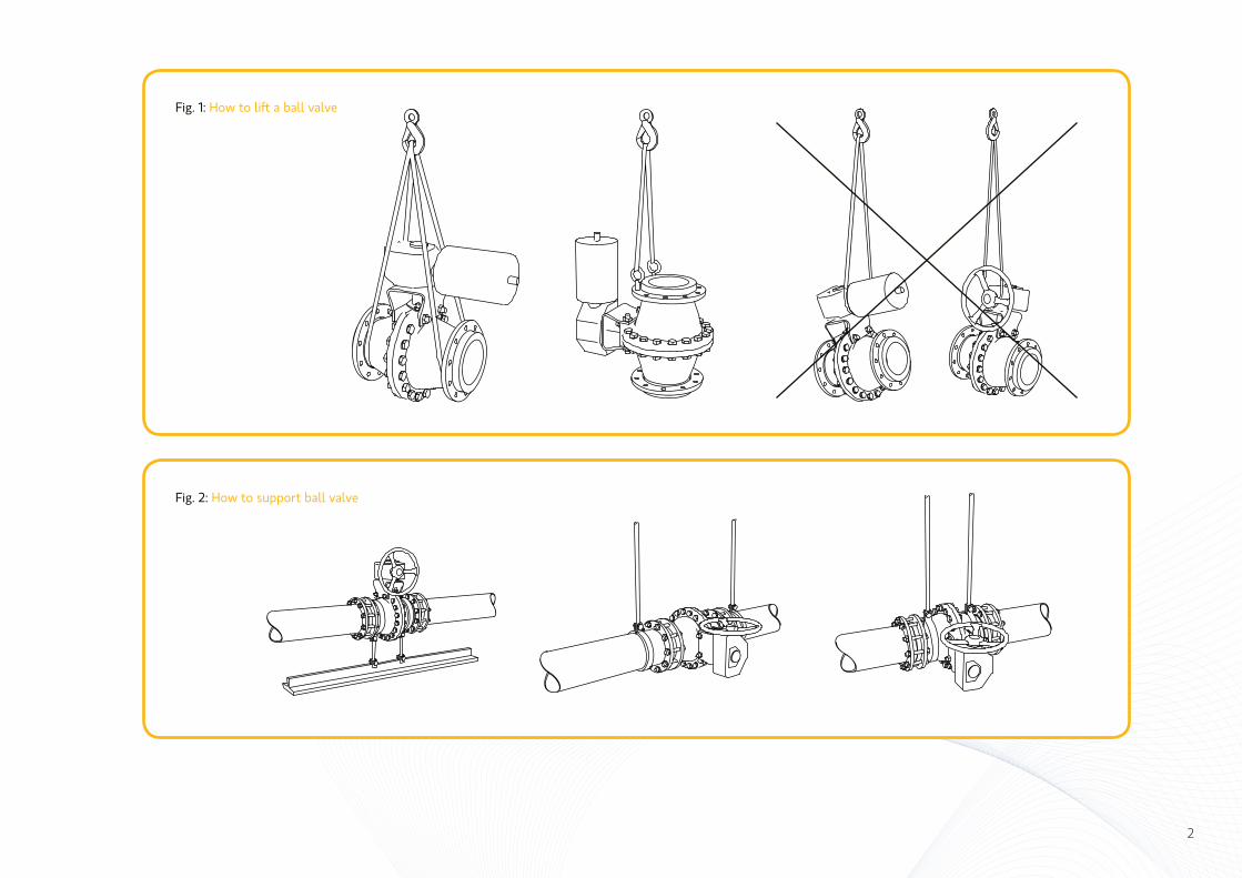
Fig. 1: How to lift a ball valve
Fig. 2: How to support ball valve
2

2.3 Supporting the valve
A well-supported pipeline minimises strain to the valve caused by vibrations in the pipeline. For maintenance it would be preferable to support the pipeline, not the valve. However, if necessary, support it by the body with pipe clamps and supports. Do not fasten supporting structures to flange bolts or to the actuator. See Fig. 2.
2.4 Start-up
Check that the pipeline is clean.
Should the valve leak when the pipeline is pressure-tested, the cause might be an insufficient quantity of testing liquid, or a very low pipeline pressure from the ball not being pressed tightly against the seat. In this case, increase the differential pressure or assist the movement of the ball, by loosening the actuator brackets, then lightly knocking the steam or body. If it is necessary to loosen the brackets, make sure that the open position does not change. The packing may leak after long storage. Tighten it uniformly with both nuts; see item 5.4.
MAINTENANCE OF THE INSTALLED VALVENo regular maintenance is necessary. However, check the gland packing tightness at regular intervals.
3.1 Gland packing
If the gland packing leaks after the nuts have been tightened to the values indicated in item 5.4.1, change the packing. The valve must not be under pressure when this is done. The change can be carried out without removal of the actuator because cut packing rings have been used. Remove the old packing with a flexible removal tool; see Fig. 3. Install the new packing as instructed in item 5.4.
Fig. 3: Removal of gland packing with a removing tool
3.
3

3.2 Body joint Should the body joint leak, tighten the nuts to the torque values given in item 5.3.2. If leaking continues, open the body and check the body joint gasket. Also check that the body joint sealing surfaces are level and undamaged; see item 5.3.1.
3.3 Ball and seats
A leak rate exceeding the acceptable values can be caused by the ball being incorrectly located between the seats or damaged sealing surfaces resulting from dirt, grit, etc.
At low differential pressures or due to the weight of the actuator, the force pressing the ball against the downstream seat can be inadequate and the valve may leak. Therefore, it will be necessary to swing the ball externally against the downstream seat by means of spacer washers located between the actuator and one of the brackets.
If damage to the downstream-sealing surface of the ball is suspected, try to stop the leak by turning the ball 180 degrees. If the leakage continues, then the downstream seat or possibly both sealing surfaces of the ball are damaged. Turn the ball back to its original position, and then turn the entire valve 180 degrees in the pipeline. Should the leakage still persist, it will be necessary to disassemble the valve and carefully check the sealing surfaces.
3.4 Jammed or stuck valve
Jamming or sticking can be caused by process accumulation between the ball and the body. Turn the ball and thoroughly flush the valve inside.
Fig. 4: Swinging the ball by means of the actuator installation brackets
4
Pressure
REPAIR OF THE VALVEIt may be necessary to remove and disassemble the valve if the above steps (in item 3) do not resolve the problems.
4.1 Removing the valve from the pipeline
First, remove the valve with its actuator from the pipeline. Then turn the valve to remove all process material. If the process is toxic or corrosive, flush the valve to avoid accidents. If the valve is going to be returned to the manufacturer for repairs, do not disassemble it.
4.2 Disassembling the valve
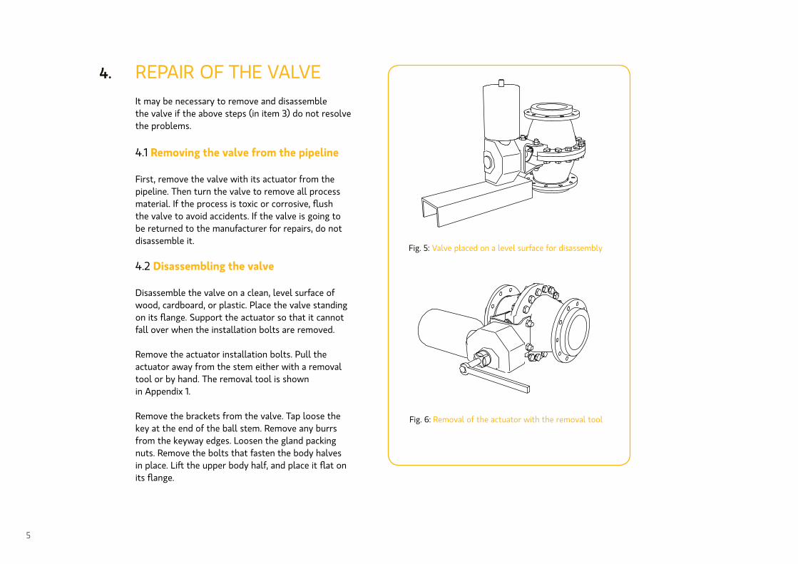
Disassemble the valve on a clean, level surface of wood, cardboard, or plastic. Place the valve standing on its flange. Support the actuator so that it cannot fall over when the installation bolts are removed.
Remove the actuator installation bolts. Pull the actuator away from the stem either with a removal tool or by hand. The removal tool is shown in Appendix 1.
Remove the brackets from the valve. Tap loose the key at the end of the ball stem. Remove any burrs from the keyway edges. Loosen the gland packing nuts. Remove the bolts that fasten the body halves in place. Lift the upper body half, and place it flat on its flange.
Fig. 5: Valve placed on a level surface for disassembly
Fig. 6: Removal of the actuator with the removal tool
4.
5
4.3 Inspection and maintenance of the valve parts
Check each part separately, and determine the steps to be taken.
4.3.1 Ball
Lift the ball from the body onto a soft surface and clean the stem. Remove impurities with emery cloth. File off any burrs from the stem keyway. If there are any deeper scratches on the sealing surfaces or if the ball is not fully spherical, it must be returned to the manufacturer for repair.
4.3.2 PTFE seats
PTFE seats do not need to be removed if they are still in good condition, unless process material has accumulated behind them. If the original seats are to be refitted, remove them very carefully by means of a thin knife or screwdriver. Insert the blade between the body lip and seat, and lift the seat from the groove from several points.
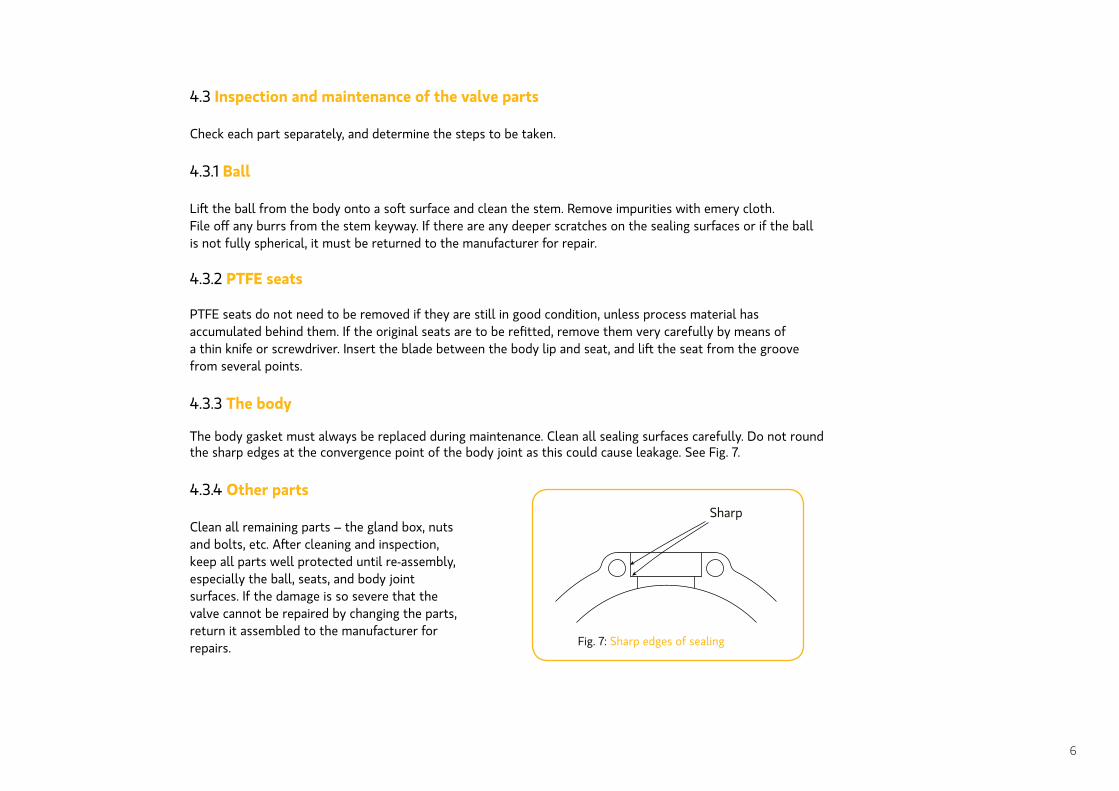
4.3.3 The body
The body gasket must always be replaced during maintenance. Clean all sealing surfaces carefully. Do not round the sharp edges at the convergence point of the body joint as this could cause leakage. See Fig. 7.
4.3.4 Other parts
Clean all remaining parts – the gland box, nuts and bolts, etc. After cleaning and inspection, keep all parts well protected until re-assembly, especially the ball, seats, and body joint surfaces. If the damage is so severe that the valve cannot be repaired by changing the parts, return it assembled to the manufacturer for repairs. Fig. 7: Sharp edges of sealing
Sharp
6
RE-ASSEMBLINGRe-assemble the valve such that the body half with a tongue in its flange lies underneath. Place this male part in an upright orientation, body joint up, on a level surface. Then install the parts in the following order:
• seats (5.2)• ball (5.2)• body joint between the body halves (5.3)• gland packing (5.4)
In each of the above phases, assemble a group of parts, the construction of which will vary slightly with the valve application. Detailed instructions and description of the construction of the groups of parts are given later. The last phase is to hammer the ball stem key into place.
5.1 Cleaning and inspection of parts
Begin by checking the parts. Remove any burrs and scratches, and again clean the internal parts. For PTFE-seated valves, check that the outer periphery of the seats is undamaged.
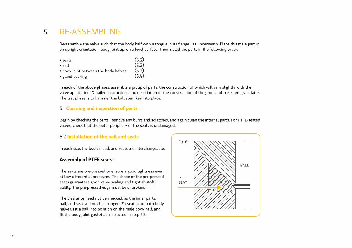
5.2 Installation of the ball and seats
In each size, the bodies, ball, and seats are interchangeable.
Assembly of PTFE seats:
The seats are pre-pressed to ensure a good tightness even at low differential pressures. The shape of the pre-pressed seats guarantees good valve sealing and tight shutoff ability. The pre-pressed edge must be unbroken.
The clearance need not be checked, as the inner parts, ball, and seat will not be changed. Fit seats into both body halves. Fit a ball into position on the male body half, and fit the body joint gasket as instructed in step 5.3.
5.
BALL
PTFE SEAT
Fig. 8
7

5.3 Body joint between the body halves
5.3.1 Fitting the body joint gasket
The gasket is a soft PTFE strip.
10
Fig. 9: Fitting the soft PTFE strip
Valve size Strip Ø Strip length
mm (in) mm (in) mm (in)
100 (4”) 5 (3/16”) 640 (25”)
125 (5”) 5 (3/16”) 785 (31”)
150 (6”) 5 (3/16”) 940 (37”)
200 (8”) 7 (3/16”) 1180 (46”)
250 (10”) 7 (5/16”) 1445 (58”)
(12”) 10 (5/16”) 1645 (65”)
(14”) 10 (5/16”) 1835 (72”)
(16”) 10 (5/16”) 2080 (82)
(24”) 10 (5/16”) 2535 (100”)
(24”) 10 (5/16”) 3090 (122”)
(28”) 10 (3/8”) 3740 (147”)
(32”) 10 (5/16”) 4210 (166”)
300
350
400
500
600
700
800
TABLE 1: Dimensions of the soft PTFE-strip
Fit the sealing strip to the body half as shown in Fig. 9.
8
Press the strip against the mounting bushing so that part of it will extrude into the packing cavity when the body halves are mounted together. Cut the strip, leaving about 5 mm extra at both ends.
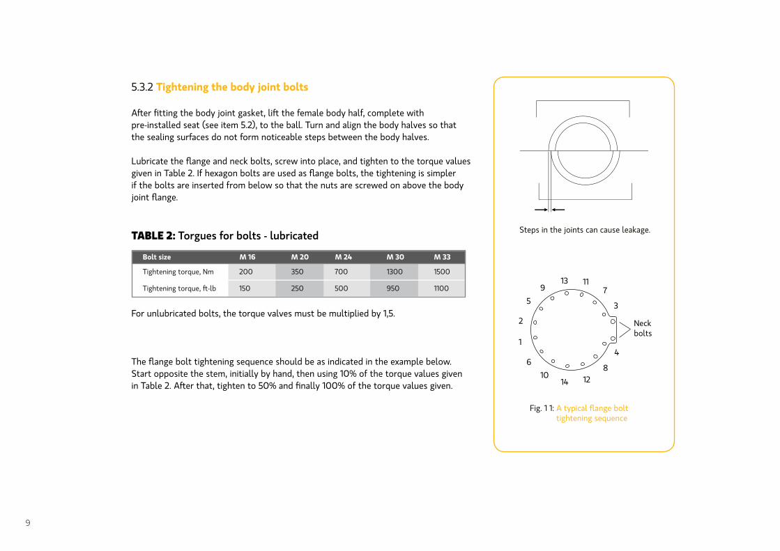
5.3.2 Tightening the body joint bolts
After fitting the body joint gasket, lift the female body half, complete with pre-installed seat (see item 5.2), to the ball. Turn and align the body halves so that the sealing surfaces do not form noticeable steps between the body halves.
Lubricate the flange and neck bolts, screw into place, and tighten to the torque values given in Table 2. If hexagon bolts are used as flange bolts, the tightening is simpler if the bolts are inserted from below so that the nuts are screwed on above the body joint flange.
For unlubricated bolts, the torque valves must be multiplied by 1,5.
The flange bolt tightening sequence should be as indicated in the example below. Start opposite the stem, initially by hand, then using 10% of the torque values given in Table 2. After that, tighten to 50% and finally 100% of the torque values given.
Fig. 1 1: A typical flange bolt tightening sequence
Steps in the joints can cause leakage.
Bolt size M 16 M 20
Tightening torque, Nm 200 350
150
M 24
700
500250
M 30
1300
950
M 33
1500
1100
1
2
3
4
5
6
7
8
9
10
11
1214
13
Neckbolts
9
TABLE 2: Torgues for bolts - lubricated
5.4 Gland packing
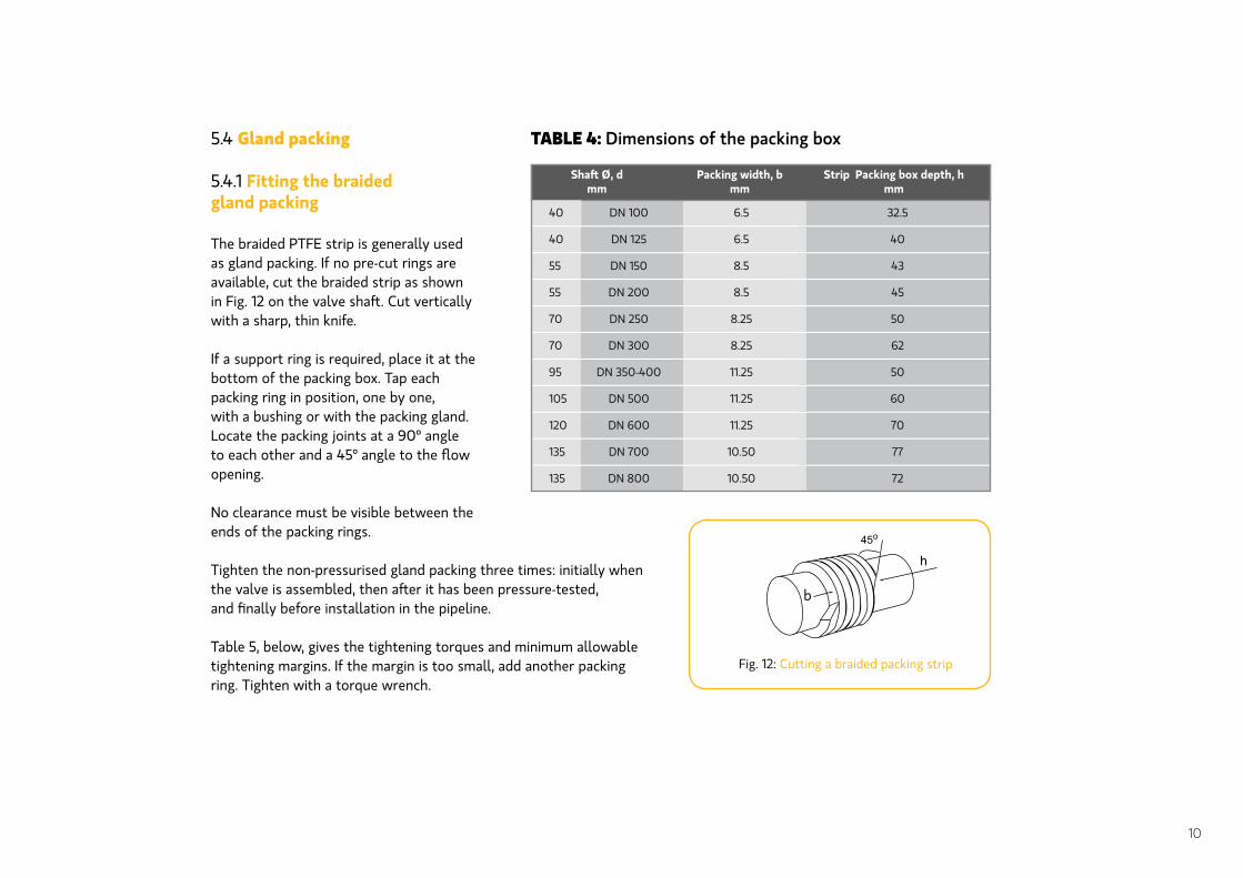
5.4.1 Fitting the braided gland packing
The braided PTFE strip is generally used as gland packing. If no pre-cut rings are available, cut the braided strip as shown in Fig. 12 on the valve shaft. Cut vertically with a sharp, thin knife.
If a support ring is required, place it at the bottom of the packing box. Tap each packing ring in position, one by one, with a bushing or with the packing gland. Locate the packing joints at a 90º angle to each other and a 45º angle to the flow opening.
No clearance must be visible between the ends of the packing rings.
Tighten the non-pressurised gland packing three times: initially when the valve is assembled, then after it has been pressure-tested, and finally before installation in the pipeline.
Table 5, below, gives the tightening torques and minimum allowable tightening margins. If the margin is too small, add another packing ring. Tighten with a torque wrench.
Fig. 12: Cutting a braided packing strip
TABLE 4: Dimensions of the packing box
h45o
b
Packing width, bmm
Strip Packing box depth, hmm
40 DN 100 6.5 32.5
40 DN 125 6.5 40
55 DN 150 8.5 43
55 DN 200 8.5 45
70 DN 250 8.25 50
70 DN 300 8.25 62
95 DN 350-400 11.25 50
105 DN 500 11.25 60
120 DN 600 11.25 70
135 DN 700 10.50 77
135 DN 800 10.50 72
10
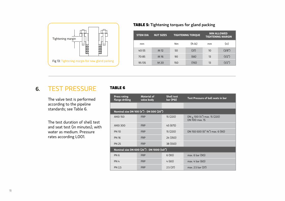
TEST PRESSUREThe valve test is performed according to the pipeline standards; see Table 6.
Fig 13: Tightening margin for new gland packing
6.
40-55
mm Nm mm (in)
M 12 50
90
150
(37)
(66)
(110)
(3/8”)
(1/2”)
(1/2”)
13
13
10
70-85 M 16
95-135 M 20
STEM DIA NUT SIZES TIGHTENING TORQUE MIN ALLOWED TIGHTENING MARGIN
TABLE 5: Tightening torques for gland packing
TABLE 6
ANSI 150 FRP 15 (220)
Nominal size DN 100 (4”) - DN 500 (20”)
Material of valve body
Shell test bar (PSI) Test Pressure of ball seats in bar
ANSI 300 FRP 45 (675)
PN 10 FRP 15 (220) DN 150-500 (6”-14”) max. 6 (90)
PN 6 FRP 6 (90) max. 6 bar (90)
PN 4 FRP 4 (60) max. 4 bar (60)
PN 2,5 FRP 2.5 (37) max. 2.5 bar (37)
PN 16 FRP 24 (350)
PN 25 FRP 38 (550)
Nominal size DN 600 (24”) - DN 1000 (40”)
11
Tightening margin
The test duration of shell test and seat test (in minutes), with water as medium. Pressure rates according L001.

Should the differential pressure across the PTFE-seated valve be lower than the test pressure for the seats, test the seats at working pressure. Choose the test pressure according to the lower pressure rating – i.e., that of the body or the flange drilling, as appropriate.
During the shell test, use blind flanges and keep the ball partly open. No leakage is allowed through PTFE-seated FRP valves with new ball and seats, when DN 500 applies.
INSTALLATION OF THE ACTUATOR7.1 Actuator
The Neles drive centre is suitable for various types of control units. Clean the stem bore. File off any burrs. Lubricate the stem bore and ball stem. Fasten the actuator brackets to the valve loosely. Insert the reducing bushing in the actuator stem bore, if required. In the actuator stem bore there are two keyways, at a 90º angle from each other. The ball stem has a keyway parallel to the flow port of the ball.
7.
TABLE 7
2 1
2 2
2 2
2 2
Nominal size DN Shell test in MIN. Seat test in MIN.
12
Fig. 14: Leak test of the valve
Water
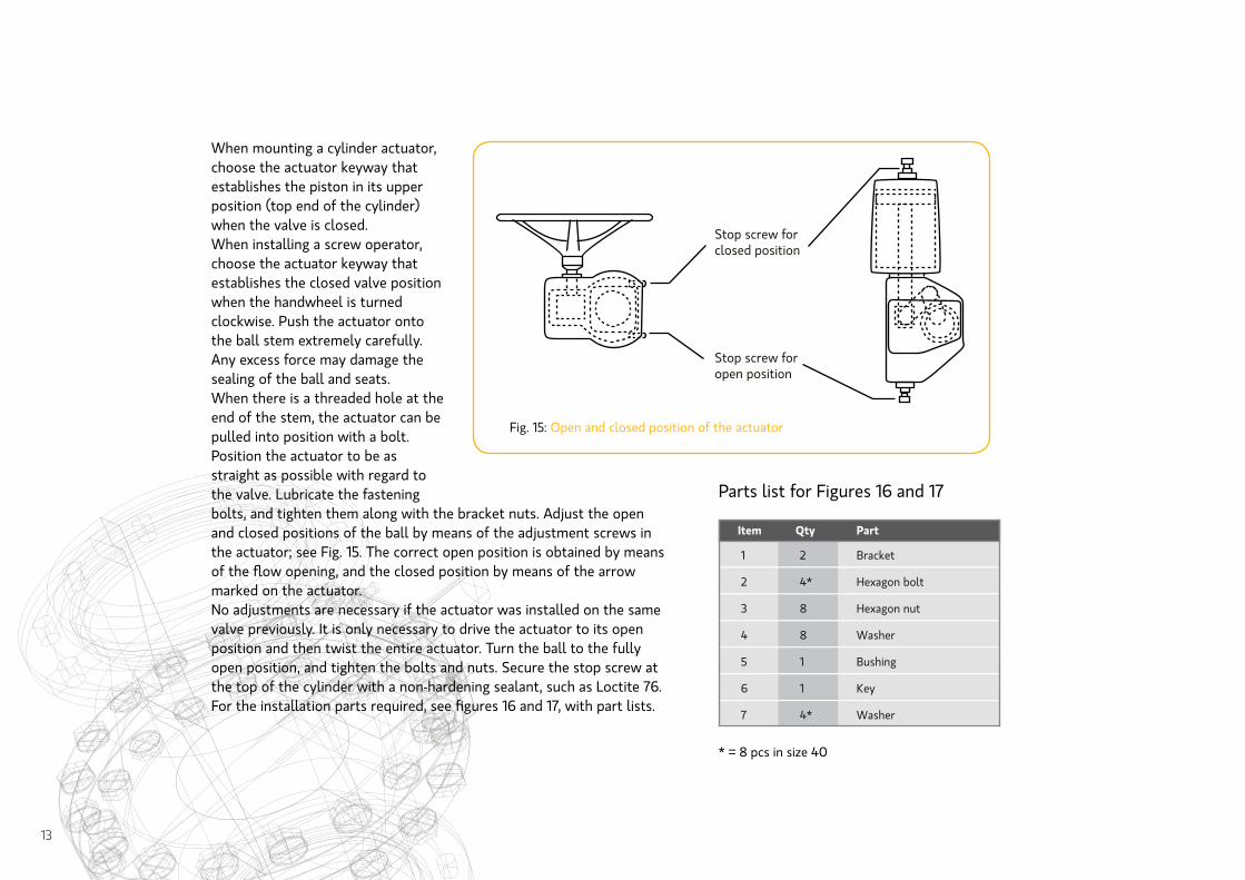
When mounting a cylinder actuator, choose the actuator keyway that establishes the piston in its upper position (top end of the cylinder) when the valve is closed.When installing a screw operator, choose the actuator keyway that establishes the closed valve position when the handwheel is turned clockwise. Push the actuator onto the ball stem extremely carefully. Any excess force may damage the sealing of the ball and seats. When there is a threaded hole at the end of the stem, the actuator can be pulled into position with a bolt. Position the actuator to be as straight as possible with regard to the valve. Lubricate the fastening bolts, and tighten them along with the bracket nuts. Adjust the open and closed positions of the ball by means of the adjustment screws in the actuator; see Fig. 15. The correct open position is obtained by means of the flow opening, and the closed position by means of the arrow marked on the actuator.No adjustments are necessary if the actuator was installed on the same valve previously. It is only necessary to drive the actuator to its open position and then twist the entire actuator. Turn the ball to the fully open position, and tighten the bolts and nuts. Secure the stop screw at the top of the cylinder with a non-hardening sealant, such as Loctite 76.For the installation parts required, see figures 16 and 17, with part lists.
Stop screw for closed position
Stop screw for open position
* = 8 pcs in size 40
1 2 Bracket
2 4* Hexagon bolt
3 8 Hexagon nut
4 8 Washer
5 1 Bushing
6 1 Key
7 4* Washer
Item Qty Part
Fig. 15: Open and closed position of the actuator
Parts list for Figures 16 and 17
13
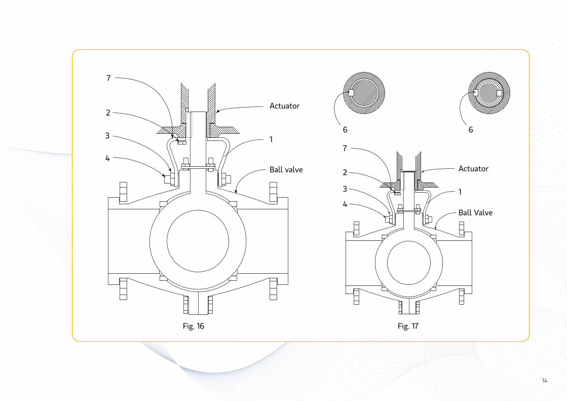
Fig. 16 Fig. 17
14
7
2
3
4
1
Ball valve
Actuator
6
7
2
3
41
Actuator
6
Ball Valve
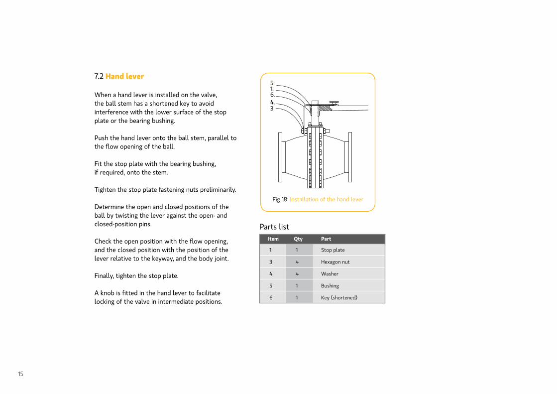
7.2 Hand lever
When a hand lever is installed on the valve, the ball stem has a shortened key to avoid interference with the lower surface of the stop plate or the bearing bushing.
Push the hand lever onto the ball stem, parallel to the flow opening of the ball.
Fit the stop plate with the bearing bushing, if required, onto the stem.
Tighten the stop plate fastening nuts preliminarily.
Determine the open and closed positions of the ball by twisting the lever against the open- and closed-position pins. Check the open position with the flow opening, and the closed position with the position of the lever relative to the keyway, and the body joint.
Finally, tighten the stop plate.
A knob is fitted in the hand lever to facilitate locking of the valve in intermediate positions.
1 1 Stop plate
3 4 Hexagon nut
4 4 Washer
5 1 Bushing
6 1 Key (shortened)
Item Qty Part
Parts list
15
Fig 18: Installation of the hand lever
5.1.6.4.3.
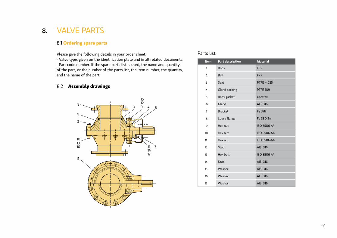
VALVE PARTS8.1 Ordering spare parts
Please give the following details in your order sheet:- Valve type, given on the identification plate and in all related documents.- Part code number. If the spare parts list is used, the name and quantity of the part, or the number of the parts list, the item number, the quantity, and the name of the part.
8.2 Assembly drawings
8.
Item Part description Material
FRP
2 Ball FRP
PTFE + C25
4 Gland packing PTFE 109
5
6 Gland AISI 316
7
8 Fe 380 Zn
9
10 Hex nut ISO 3506-A4
11
12 Stud AISI 316
13
14 Stud AISI 316
15
16 Washer AISI 316
17
1 Body
3 Seat
Body gasket Coretex
Bracket Fe 37B
Hex nut ISO 3506-A4
Hex nut ISO 3506-A4
Hex bolt ISO 3506-A4
Washer AISI 316
AISI 316Washer
16
Parts list
8
1
2
101316
5
3
15129 4 6
7111417
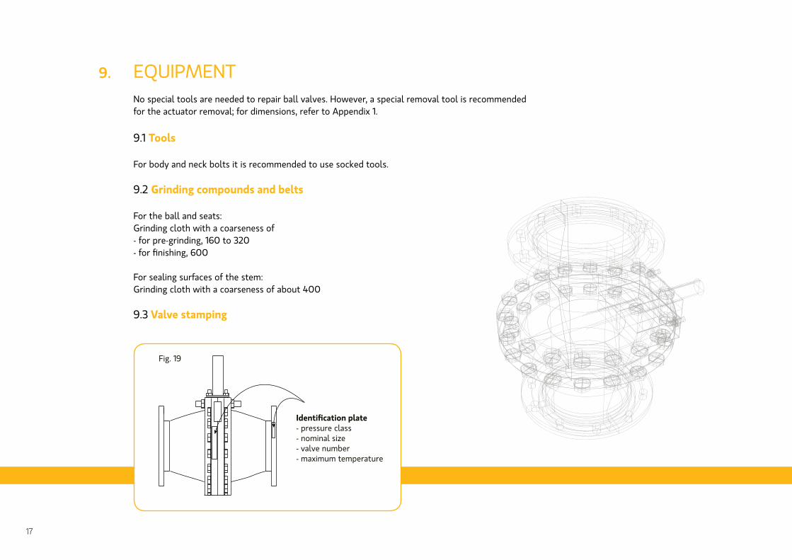
EQUIPMENT No special tools are needed to repair ball valves. However, a special removal tool is recommended for the actuator removal; for dimensions, refer to Appendix 1.
9.1 Tools
For body and neck bolts it is recommended to use socked tools.
9.2 Grinding compounds and belts
For the ball and seats:Grinding cloth with a coarseness of- for pre-grinding, 160 to 320- for finishing, 600
For sealing surfaces of the stem:Grinding cloth with a coarseness of about 400
9.3 Valve stamping
9.
17
Identification plate- pressure class- nominal size- valve number- maximum temperature
Fig. 19
18

19

V
ATS
RP
O
U
Pos 1 2
Pos 3
Z Y
V
XX B D
90o
30o
Molykote BR2
25CrMo4
Du/Ds x 2
Fe52D
esim. / e.g. ESAB OK 75.65
Fe 50
C
U
DD
BB
H
FAA G
K
Pos 4 8J
CC
L
D
N
M
20
Lubricating:Electrode:
Supporting ring:
42CrMo4 or
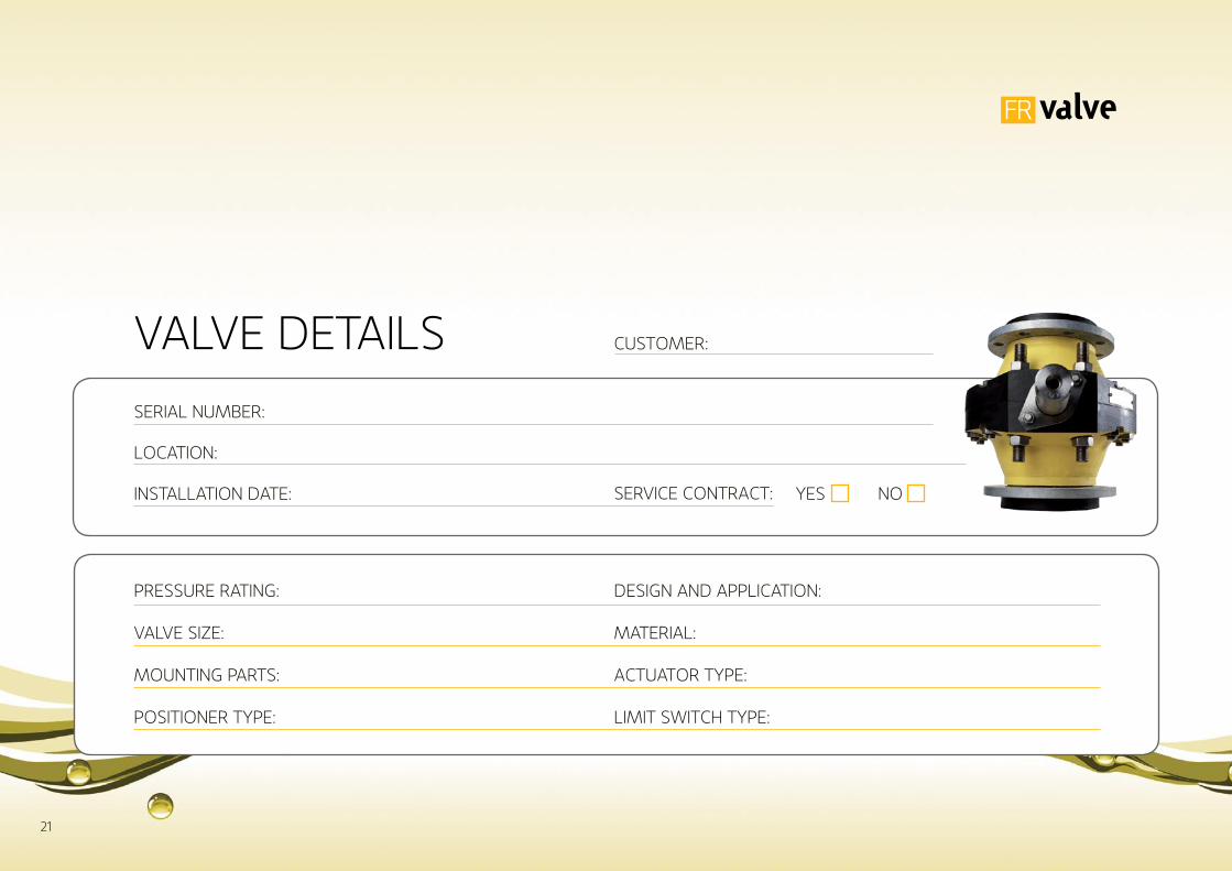
SERIAL NUMBER:
LOCATION:
INSTALLATION DATE:
PRESSURE RATINg:
VALVE SIzE:
MOUNTINg PARTS:
POSITIONER TyPE:
yES NOSERVICE CONTRACT:
DESIgN AND APPLICATION:
MATERIAL:
ACTUATOR TyPE:
LIMIT SwITCh TyPE:
VALVE DETAILS CUSTOMER:
21

DATE SERVICE MAINTENANCE
DATE SERVICE MAINTENANCE
DATE SERVICE MAINTENANCE
DATE SERVICE MAINTENANCE
DATE SERVICE MAINTENANCE
DATE SERVICE MAINTENANCE
DATE SERVICE MAINTENANCE
DATE SERVICE MAINTENANCE
22

Oy FR Valve Products AbLötvägen 2, FI-68570 Larsmo, Finland, www.frvalve.fi, [email protected]
TEL +358 (0)6 781 55 00, FAX +358 (0)6 781 55 49, MOBILE +358 (0)50 512 3723