frp composites bridge applications - university at buffalo - 9-21-09... · · 2009-09-28bridge...
TRANSCRIPT

FRP Composites for
Bridge Applications
September 21, 2009
Jerome S. O’Connor, PE, F, ASCEMCEER Senior Program Officer, Transportation Research
University at Buffalo
CIE‐500 Prof. George C. Lee; 340C Bell Hall

DefinitionDefinition
• FRP: Fiber Reinforced Polymer• Composite: A man‐made (i.e. engineered) material that combines two or more components to make a material with improved properties over either of the two individual constituents. Each of the two components works in harmony with the other(s) but retain their own chemical and physical properties.

OutlineI. FRP BasicsII. Civil Engineering Applications
– Rebar (ppt)– Seismic Retrofitting (go to)– Aerodynamic Improvement (go to)
– Concrete Strengthening using sheet, rods, strips, plates (Techniques for strengthening steel with FRP is still evolving)
• Beams• Columns Court St
– Overhead Sign Structure Repair (go to)– Culvert Relining (go to)– Bridge Decks Bentley– Bridge Superstructures New Oregon PR‐139
III. Handouts & References (go to)

General FRP Applications

Aerospace Applications
787
Bridge of the Future
•• Long lifeLong life•• Less $Less $•• FastFast•• Minimal maintenanceMinimal maintenance•• Shock resistantShock resistant•• AdaptableAdaptable•• (Reduced carbon footprint)(Reduced carbon footprint)

Available FRP Products
•• Concrete reinforcement (2)Concrete reinforcement (2)•• External Concrete ReinforcementExternal Concrete Reinforcement
–– Fiber sheets (8)Fiber sheets (8)–– Near surface mounted rods and strips (3)Near surface mounted rods and strips (3)
•• FRP decks (8)FRP decks (8)•• FRP superstructures (6) FRP superstructures (6) •• Repair kits for aluminum overhead sign structures (2)Repair kits for aluminum overhead sign structures (2)•• Linings for existing culverts (3) Linings for existing culverts (3) •• Structural shapes (4)Structural shapes (4)

Examples of Composites
• GFRP (glass fiber reinforced polymer)• CFRP (carbon fiber reinforced polymer)• AFRP (aramid fiber reinforced polymer)• Wood with cellulose fibers is a natural composite• Reinforced concrete uses steel reinforcing in a cement and aggregate matrix
• Renewable materials (natural fiber such as hemp combined with bio‐resins)
• MMC (metal matrix composite)• CMC (ceramic matrix composite)• ECC (engineered cementitious composite, aka ‘bendable concrete)

Definition
FRP = Fiber Reinforced Polymer Composite
CarbonE‐GlassAramidPhenolics
EpoxyVinyl EsterPolyester
Each component retains it own properties yet act in concert with one another.
thermo‐set

Advantages
•• Light weight (high strengthLight weight (high strength‐‐toto‐‐weight ratio)weight ratio)•• Corrosion resistantCorrosion resistant•• Chemical resistantChemical resistant•• AnisotropicAnisotropic•• High tensile strengthHigh tensile strength•• Fatigue resistantFatigue resistant•• Potential for good, consistent qualityPotential for good, consistent quality•• EngineerEngineer‐‐ableable•• NonNon‐‐magneticmagnetic
Steel bridge beam

AdvantagesHybrid Use e.g. Enhance concrete compressive strength

Disadvantages
• Higher initial material cost
• Civil engineers typically have little education and experience with composites; Contractors and construction crews are very familiar with concrete, steel, asphalt and less so with FRP
• Failure of fibers is not ductile
• More sophisticated design is sometimes needed (e.g. Finite Element Analysis , FEA)

Design Considerations
• Low shear strength relative to tensile
• Low modulus of elasticity (~ stiffness)
• Susceptible to creep under sustained loading
• Needs UV protection
• Anisotropic
• Theoretically engineer‐able (may not be practical in practice; standard designs may be more cost effective)

Manufacturing Methods
• Filament winding (used mainly for pipes)
• Hand Lay‐up
• Pultrusion
• Vacuum Assisted Resin Transfer Molding (VARTM)
• Shop fabrication vs. field

Manufacturing Methods‐ Pultrusion ‐
creelresin tank
shapingand
heating die
puller
video
Fibers in pultrusions are predominately uni‐directional (longitudinal).

Manufacturing Processes
Open Mold hand lay up

Manufacturing MethodsVARTM
Strength Determined by
• Type of fiber
• Type of resin
• Fiber volume fraction
• Fiber orientation
• QC during manufacturing
• Rate of Curing

Post‐cure
• Some composites, especially one used for aerospace applications are heated to accelerate the cure and increase its strength
• Field applications on bridges (such as column wrapping) typically do not get a post cure

PROPERTIES

Thermo‐plastic vs. Thermo‐set
• Thermo‐plastic: resin has a melting temperature at which it turns to a liquid. It can be recooled to form a solid again. Thermoplastic resins are easily recyclable.
• Thermo‐set: a liquid resin hardens only after addition of a catalyst in a non‐reversible chemical reaction. It does not melt into a liquid a high temperatures but has a glass transition temperature (Tg) at which the mechanical properties change and it loose strength. Most civil applications use thermo‐set composites.

Linear Elastic
• Fibers do not exhibit ductility prior to rupture
• Linear elastic until failureMoment vs. FRP Stress/Strain
111.859.7
559.0
21.5
18.10
1000
2000
3000
4000
5000
0 100 200 300 400 500 600FRP Stress (MPa)
Mom
ent (
kN*m
)
0%
20%
40%
60%
80%
100%
0 2000 4000 6000 8000 10000 12000
FRP Strain (microstrain)
Perc
enta
ge o
f Ulti
mat
e
Ultimate Allowable (20% of Ultimate)At Concrete Allowable Stress Total Design Loads with impactAdjusted Design Loads based on Load Testing

Creep
• Deformation (i.e. deflection) under sustained load
• Can lead to creep rupture (sudden failure)
• Potential problems can be avoided by keeping dead load stresses < 20‐30% of FRP ultimate tensile strength

Anisotropic

Stiffness
• Stiffness is driven by Modulus of Elasticity E for a given Moment of Inertia I
• Bending Rigidity = EI
• E can vary
• CFRP can have a higher E than steel
• GFRP has a low E. Despite this, GFRP is typically used for bulk applications because of cost

Material CharacteristicsDetermined by
• Type of fiber
• Type of resin
• Fiber volume fraction
• Fiber orientation
• QC during manufacturing
• Rate of Curing

Fiber Architecture
• Type of fiber• Weave vs. uni‐directional• Number of layers• Fiber orientation• Void Ratio (want <1%)• Fiber content
– % by weight – convenient for fabricator to use – % by volume determines strength and long term durability
• The fibers are the load carrying component of the FRP so the higher the fiber density, the higher the strength of the composite
• Denser material reduces the potential for water intrusion

% Fiber by volume
• 100% is not physically possible– Resin takes up space
– Even dry packing fibers would result in voids between fibers
• Typical– High grade aerospace: 50%‐75%
– Civil applications• Pultruded in factory: 30%‐60%
• Field application: 25%‐30%
• VARTM

Thermal Properties
• Different from materials conventionally used in civil works projects
• Different behavior in each direction
• CFRP coefficient of thermal expansion (CTE) is negative
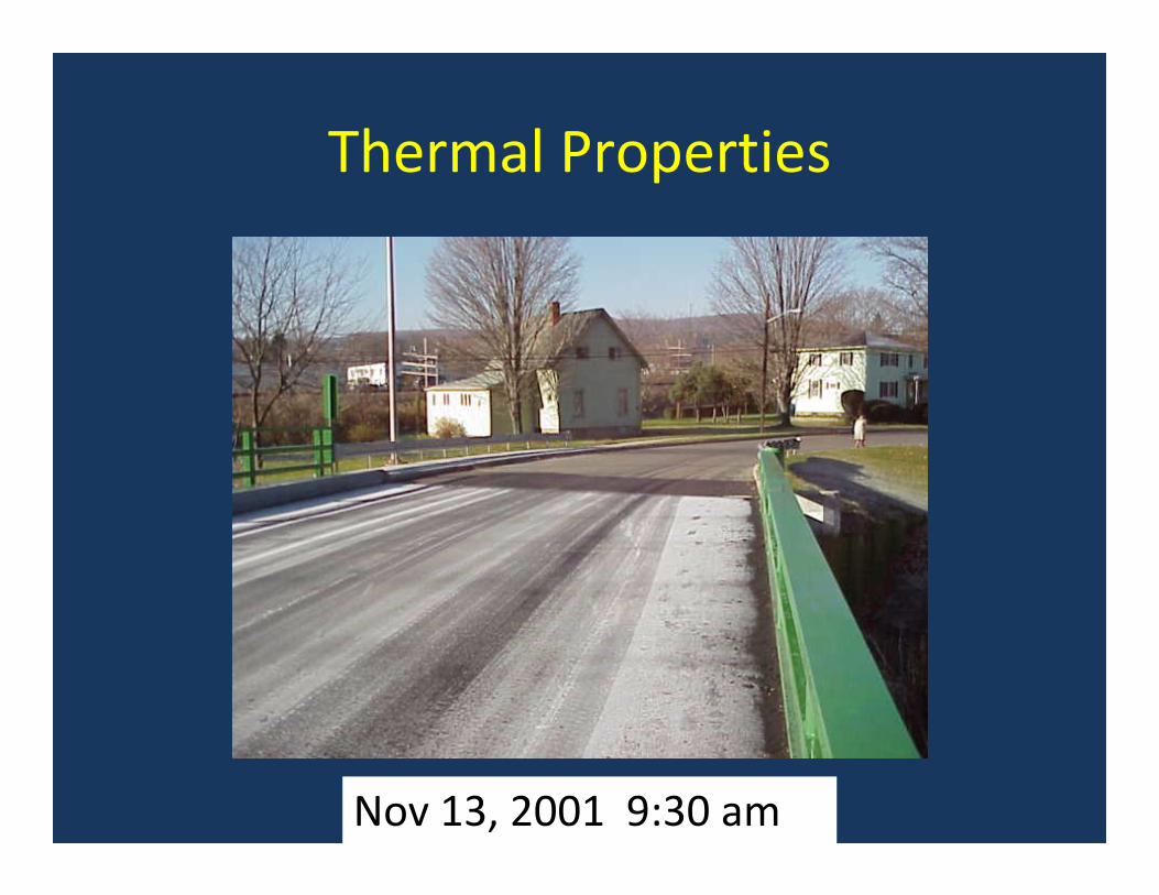
Thermal Properties
Nov 13, 2001 9:30 am

Sample Temperature Gradient
Temperature readings at 248 / Bennetts Creek 6/1 BIN 1043150

Sample Temperature Gradient
POSSIBLE RESULTS: 1) Panel can “hog”; 2) High thermal stresses
Time
Bottom skin temperature in
°F
Top wearing surface
temperature in °F (black color)
Difference
7:30 AM 62 64 28:00 AM 63 70 78:30 AM 63 74 119:00 AM 62 87 259:30 AM 66 105 39
10:00 AM 68 119 5110:30 AM 70 128 5811:15 AM 72 138 6612:00 PM 74 148 741:00 PM 73 150 77
Temperature readings at 248 / Bennetts Creek 6/1 BIN 1043150

Hygral
• Hygral expansion and relaxation shrinkage
• Need to prevent water intake from extended immersion or high humidity
Fatigue
• FRP is good in fatigue but good quality control during fabrication is essential to getting good results.
• Tested and used extensively in other industries (aerospace, military, sports)

Connections
• Bonded (examples of adhesives are listed below)– ITW’s Plexus (methyl‐methacrylate)
– Ashland’s Pliogrip (polyurethane)
– ProSet (two‐part epoxy)
– Loctite, 3M, Permabond (acrylic)
• Mechanical
• Hybrid

Properties Time Dependant
• Materials degrade over time (~5% over 100 year life)
• Account for this using “knockdown” factors for material properties

Fire & Heat Resistance
• Will not support flame spread due to lack of oxygenand high % of fiber
• Resin softens at Glass Transition Temperature (Tg) e.g. 150‐250 degrees
• At 480 degrees F, tests show 20% strength reductio
• At Tg bond strength may reduce by 40%
vs. Steel & Concrete

FRP vs. SteelCan have greater Can have greater ultimate strengthultimate strength
Standard gradesStandard grades
Linearly elastic until Linearly elastic until failure, i.e. no yieldingfailure, i.e. no yielding
Elastic until yield pointElastic until yield point
Sudden brittle failureSudden brittle failure Exhibits Exhibits ductilityductility in in plastic rangeplastic range
Shear strength typically Shear strength typically 1/25 of tensile1/25 of tensile
Shear strength is Shear strength is ½½ of of tensiletensile
Low E and low stiffnessLow E and low stiffness E = 29,000,000 psiE = 29,000,000 psi
Uni directional propertiesUni directional properties isotropicisotropic

Material CharacteristicsTensile Strength
ksiksiEE--glassglass CarbonCarbon AramidAramid SteelSteel ConcreteConcrete
70 to 23070 to 230 87 to 53587 to 535 250 to 250 to 368368
70 to 70 to 100100
NANA
per ASTM D3039

0
50
100
150
200
250
300
ksi
HP Steel E-Glass Carbon
Material CharacteristicsMaterial CharacteristicsUltimate Tensile StrengthUltimate Tensile Strength

Material CharacteristicsRupture Strain
% at failure% at failure
EE--glassglass CarbonCarbon AramidAramid SteelSteel ConcreteConcrete
1.2 to 3.11.2 to 3.1 0.5 to 1.70.5 to 1.7 1.9 to 4.41.9 to 4.4 6 to 126 to 12 NANA

0
0.05
0.1
0.15
0.2
0.25
0.3
pci
HP Steel E-Glass Carbon
FRP density is approximately 1/5 that of steel
Material CharacteristicsMaterial CharacteristicsDensityDensity

Material CharacteristicsCoefficient of Thermal Expansion (CTE)
• Anisotropic so very different properties parallel and perpendicular to the fibers
• Negative CTE means material shrinks as temperature rises
CTE, X 10CTE, X 10--66/F/F
EE--glassglass CarbonCarbon AramidAramid SteelSteel ConcreteConcrete
LongitudinalLongitudinal 3.3 to 3.3 to 5.65.6
--4 to 04 to 0 --3.3 to 3.3 to --1.11.1
6.56.5 5.55.5
TransverseTransverse 11.7 to 11.7 to 12.812.8
41 to 41 to 5858
33.3 to 33.3 to 44.444.4
6.56.5 5.55.5

Material CharacteristicsE: Modulus of Elasticity
E, X 10E, X 10--3 3 ksiksi
EE--glassglass CarbonCarbon AramidAramid SteelSteel ConcreteConcrete
3.3 to 3.3 to 5.65.6
15.9 to 15.9 to 8484
6 to 18.26 to 18.2 2929 NANA

Typ. Stress‐Strain Relationship
E‐glass
Carbon
Steel
Stress
StrainE steel = 29,000,000 psi
E = 3,500,000 psi

$0.0000
$0.0020
$0.0040
$0.0060
$0.0080
$0.0100
$0.0120
$0.0140
$0.0160
Carbon/epoxy rod Glass/polyesterrod
High StrengthSteel bar
HPS 485W Steel A588 Steel
Material CharacteristicsMaterial CharacteristicsCost for yield StrengthCost for yield Strength


BRIDGE APPLICATIONS


OutlineI. FRP BasicsII. Civil Engineering Applications
–Rebar (ppt)– Seismic Retrofitting (go to)– Aerodynamic Improvement (go to)– Concrete Strengthening using sheet, rods, strips, plates (Techniques for strengthening steel with FRP is still evolving)
• Beams• Columns Court St
– Overhead Sign Structure Repair (go to)– Culvert Relining (go to)– Bridge Decks Bentley– Bridge Superstructures New Oregon PR‐139
III. Handouts & References (go to)

Seismic
• Column Wrap– Adds confinement
– Improves shear
– Improves ductility
– Reduces possibility of lap splice failure
– http://www.fhwa.dot.gov/bridge/frp/calcomp.htm
• UB In‐fill panels
• Concrete arch retrofit

SeismicSeismic
In‐fill panel
University at Buffalo’s Lee, Aref, Kitane
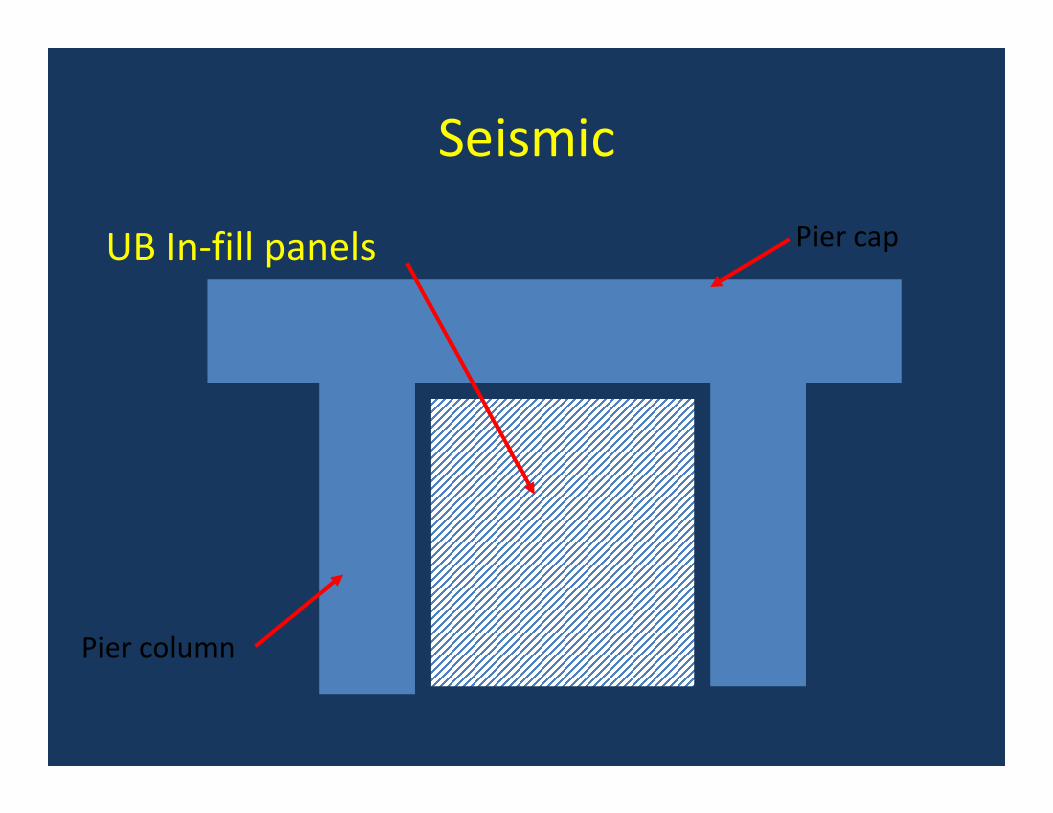
Seismic
UB In‐fill panels Pier cap
Pier column

Seismic
Woodlawn Viaduct, NYby R. J. Watson / Fyfe


Aerodynamics
Bronx‐Whitestone Bridge, NYCby Hardcore Composites


Strengthening Concrete
• Maintenance Applications – Beams
– Columns
– Strengthening
– Column wrapping for deterioration
• Concrete arch rehabilitation

Strengthening ConcreteBeams
• Strengthening– To increase load capacity
– Deficient design

Strengthening ConcreteColumns
• Strengthening
• Improving ductility
• Column wrapping for deterioration– Court St. evaluation
– Railroad over I‐86

Strengthening ConcreteCourt St. Columns
Court St. PPT

Strengthening ConcreteI‐86 Columns
• Railroad over I‐86

Strengthening ConcreteColumns
Sealing the top

Typical Humidity Data
PIER 3 RIGHT COLUMN
0
20
40
60
80
100
120
9/98 3/99 10/99 4/00 11/00 5/01
Date Recorded
HU
MID
ITY
(%) AMBIENT
BEGINSIDE END SIDE RIGHTSIDE

Sample Corrosion Data
PIER 5 LEFT COLUMNCORROSION SENSORS
012345678
9/98 3/99 10/99 4/00 11/00 5/01
Date Recorded
Cor
rosi
on R
ate
(mils
per
yea
r)
BEGINSIDE
ENDSIDE
RIGHTSIDE

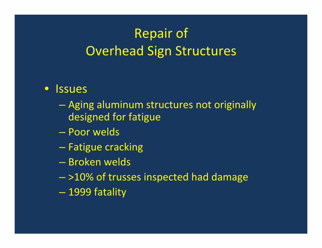
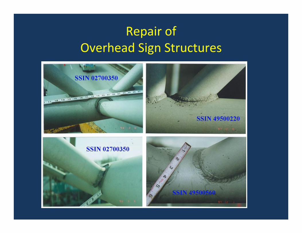
Repair of Overhead Sign Structures
• Issues– Aging aluminum structures not originally designed for fatigue
– Poor welds– Fatigue cracking– Broken welds– >10% of trusses inspected had damage– 1999 fatality

Repair of Overhead Sign Structures

Repair of Overhead Sign Structures
Repair of Overhead Sign Structures

Repair of Overhead Sign Structures

Repair of Overhead Sign Structures

Repair of Overhead Sign Structures

Repair of Overhead Sign Structures
• Benefits– May be used to temporarily repair an OSS (may prove to be a long term repair)
– Time efficient (<3 hours/joint)
– Personnel efficient (3 workers)
– Cost effective (<$3,000/joint)
– Allows replacements to be scheduled, rather than on emergency basis

Repair of Overhead Sign Structures
• Resources– Harry White, NYSDOT (518) 485‐1148
– Franz Worth, Air LogisticsCorp.(626) 633‐0297
– Sarah Witt, Fyfe Co.(858)642‐0694
– AASHTO Technology Implementation Group– http://www.dot.state.ny.us/tech_serv/trdb/files/winter2003.pdf


Culvert Re‐liningErie County, NY

Buffalo, NY
Dick Road Culvert BR 317Dick Road Culvert BR 317‐‐4 over U4 over U‐‐Crest DitchCrest DitchErie County NY Town of CheektowagaErie County NY Town of Cheektowaga
Problem Statement
1. Replace or reline corroded steel multi‐plate arch on concrete footings.
2. Maintain 38,500 vehicles per day.

Solution
Reline the existing structure with an fiber reinforced polymer (FRP) liner to avoid disruption of traffic.

Culvert Re‐liningErie County, NY

Culvert Re‐liningFRP insert

Culvert Re‐liningFRP Inserts

Culvert Re‐lining

Culvert Re‐lining
$300,000 construction cost


DECKS & SUPERSTRUCTURES

FRP Bridge Decks
CP SuperDeck CP SuperDeck‐ gen2
BP ProDeck 8 BP ProDeck 4

FRP Bridge Decks
Hardcore Composites MMC Duraspan
xxx xxx

Deck design considerations

Deck & Superstructure Design Considerations (1)
• Standard AASHTO design vehicle (HS20, HS25, HL93)• Allowable Stress Design (ASD) used
– In ASD, the member is selected so that the area and moment of inertia are large enough to prevent the maximum induced stress and deflection from exceeding the allowable values.
• Deflection criteria – L / 800 is typical for end supported superstructure slab (global
deflection)– Stringer supported bridges are predesigned by the supplier. (S / 500)
(deck deflection in relation to stringers) • Allowable stress limits for DL (10%) & DL/LL/impact (20%• Connections to stringers
– Composite behavior vs. need to avoid cracking– Composite behavior can be obtained between FRP deck and
steel stringer using shear studs, but the composite moment of inertia is only 7% higher than that of steel plate girder moment of inertia

Deck & Superstructure Design Considerations (2)
• Field joints between panels• Bridge joints at end of bridge or over piers• Drainage
– Cross slope– Scuppers– Curbs
• Ease of installation, special cutouts• Wearing surface• Bridge railing• Fatigue

Special Details
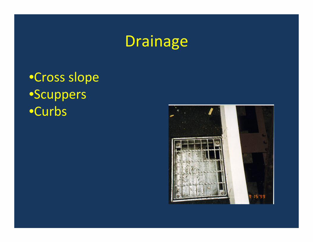
Drainage
•Cross slope•Scuppers•Curbs

Haunch

Connections
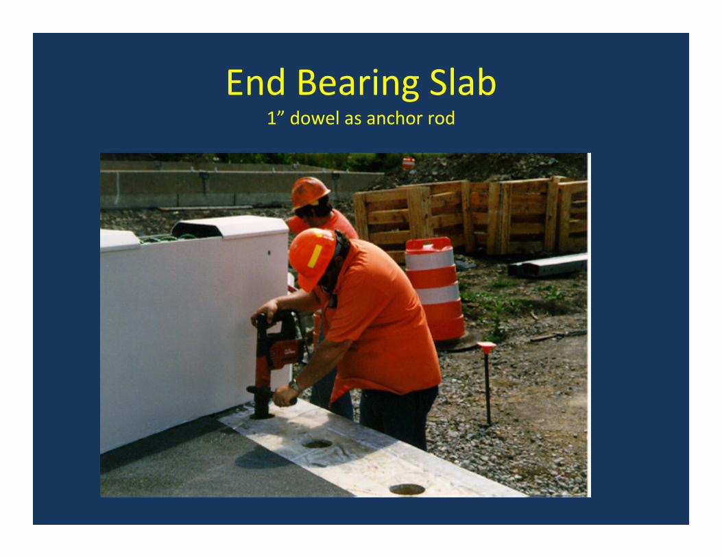
End Bearing Slab1” dowel as anchor rod

Deck to Steel Connections
• Stud Shear Connectors
• S‐Clips
• Bolted connection
• Adhesives
• Pop rivets
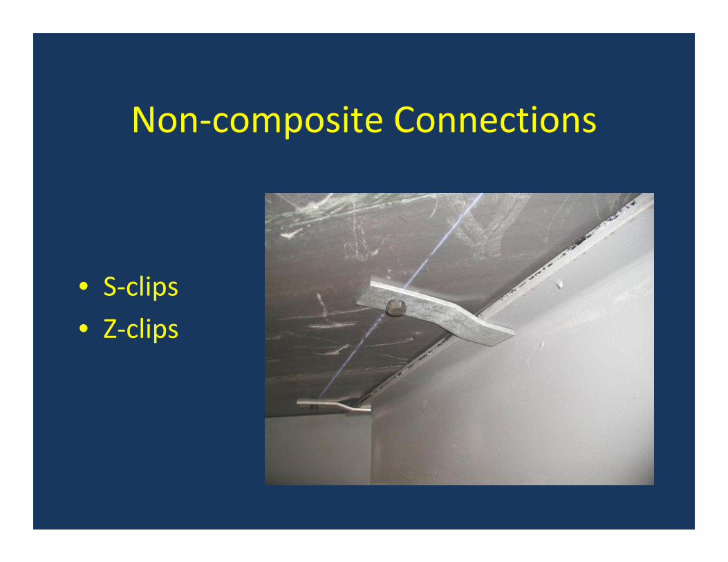
Non‐composite Connections
• S‐clips
• Z‐clips

Composite Connections
Stud shear connectorsStud shear connectors

Stud Sear Connectors
Formed haunch

Stud Shear Connectors

Stud Shear Connectors

Bolted Connection

Adhesives
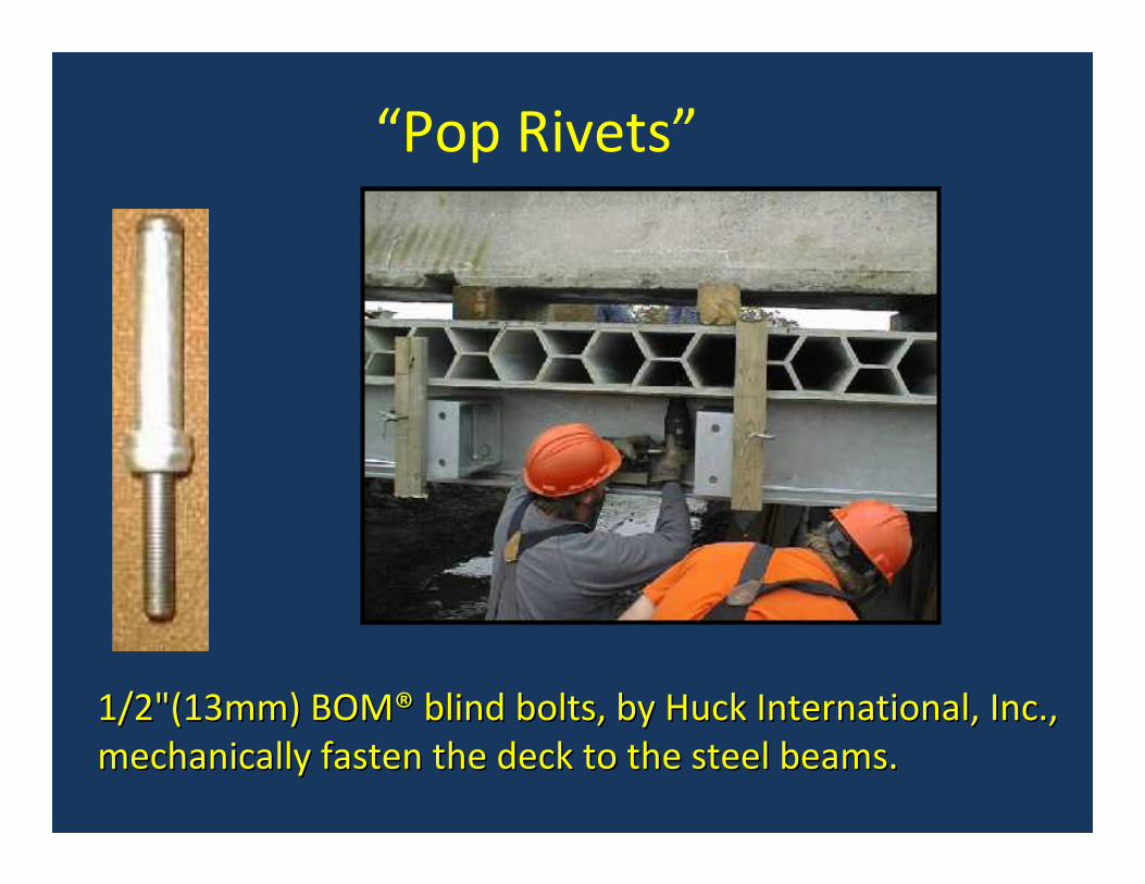
1/2"(13mm) BOM1/2"(13mm) BOM®® blind bolts, by Huck International, Inc., blind bolts, by Huck International, Inc., mechanically fasten the deck to the steel beams.mechanically fasten the deck to the steel beams.
“Pop Rivets”

Connection to Concrete
Field Joints
• A wet lay‐up to reinforce the joint has been found to be effective in reducing reflective cracks over the adhesive joints between panels

Wearing Surface

Wearing SurfacesPolymer Concrete (thin, watertight but not as familiar) 48% of projects
1) Epoxies2) Polyesters3) MMA
Asphalt (heavy & porous but easy & familiar) 41% of projects
1) 2” Superpave2) 1/2” microsurfacing3) polymer modified asphalt
PCC or Latex modified Portland cement concrete 11% of projects

Prototype Wearing Surfacedeveloped for NYSDOT by R. Aboutaha at Syracuse University
Performance Objectives•Permanent bond•Skid resistance, durability, protection of FRP
3/8” PolymerConcrete (for bond)
FRP deck surface
1” Polymer ModifiedConcrete (for wear)

Bridge Railing

Overview of Experience in the U.S. with
FRP Decks & Superstructures
Jerome S. O’Connor, P.E., F,[email protected]

Sample FRP Deck Sections

Sample FRP Superstructures

Pedestrian bridgesE. T. Techtonics
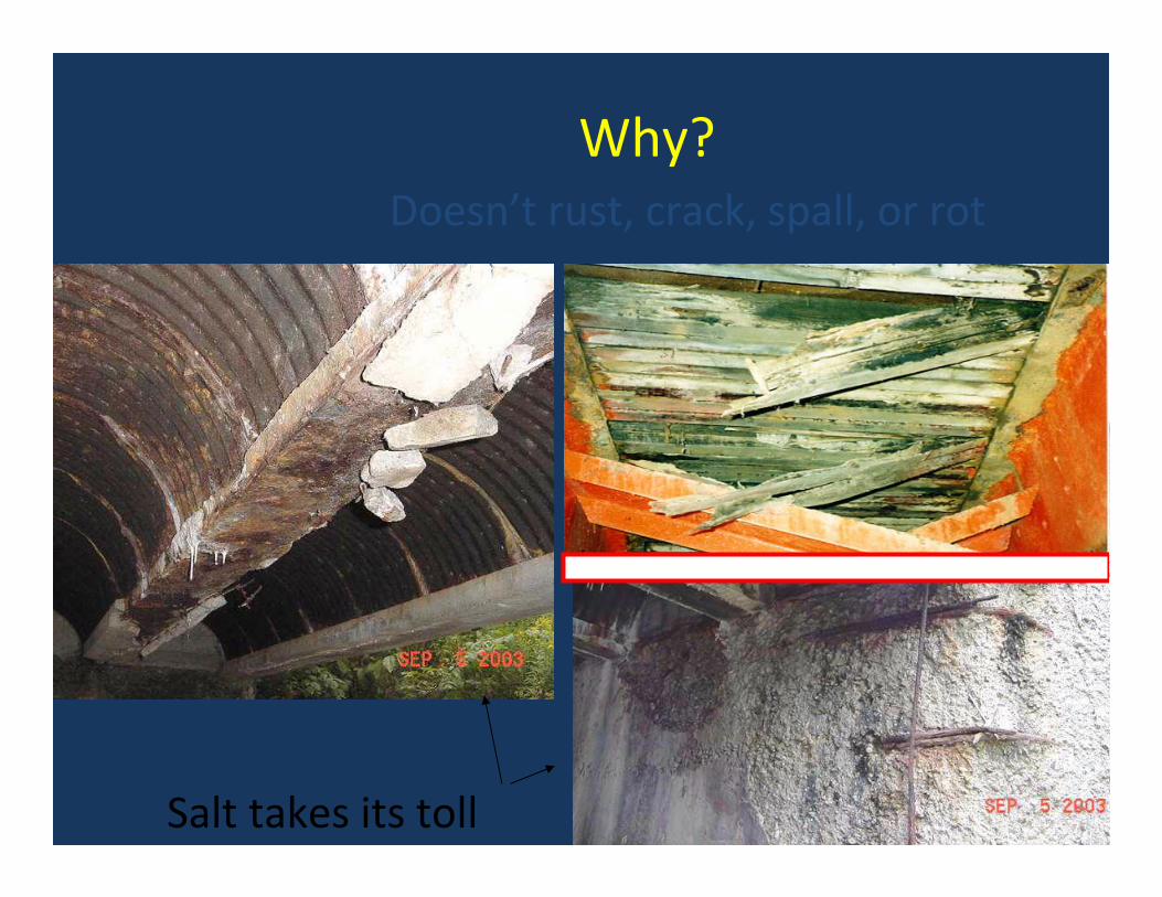
Why?
Salt takes its toll
Doesn’t rust, crack, spall, or rot
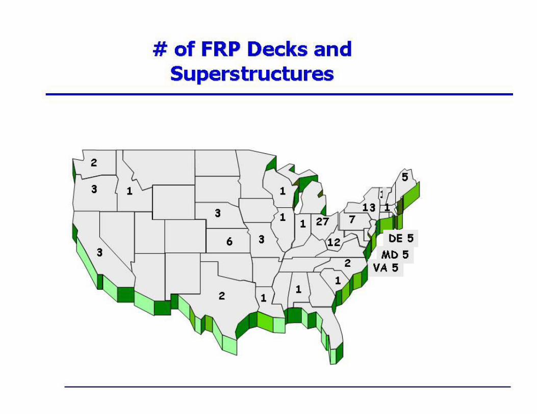
Where they are…

Manufacturers
has supplied only 1 or 2
*
*
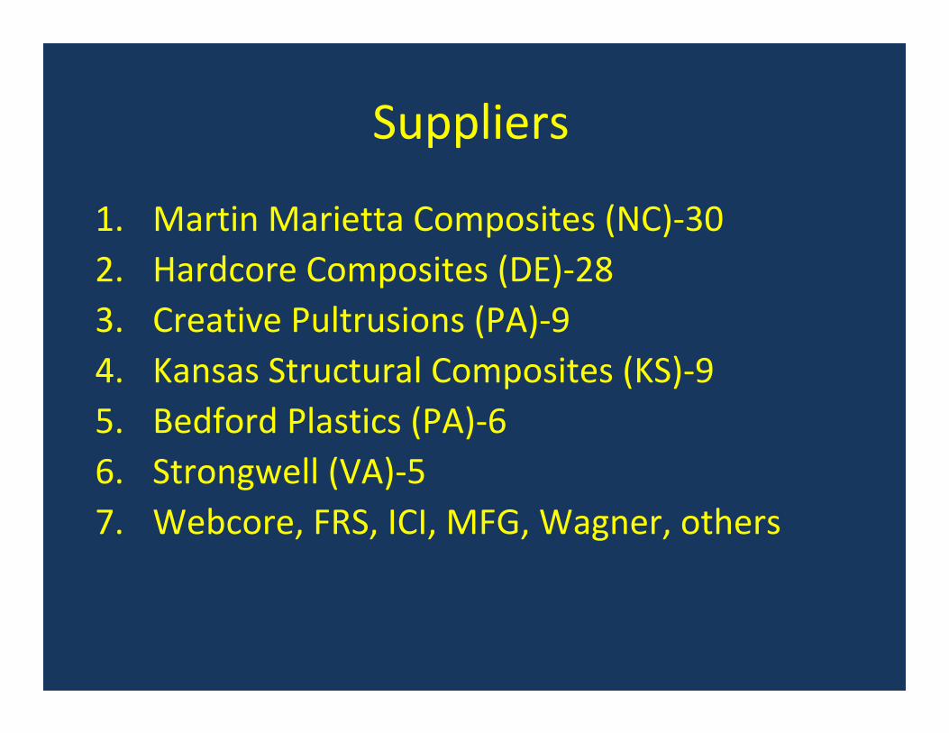
Suppliers
1. Martin Marietta Composites (NC)‐30 2. Hardcore Composites (DE)‐28 3. Creative Pultrusions (PA)‐94. Kansas Structural Composites (KS)‐95. Bedford Plastics (PA)‐66. Strongwell (VA)‐57. Webcore, FRS, ICI, MFG, Wagner, others

Manufacturing Processes
andwich Constructionandwich Constructionvs. Pultrusionvs. Pultrusion

Manufacturing Processes
1. VARTM (vacuum assisted resin transfer molding)
2. Open‐mold hand lay‐up
3. Pultrusion
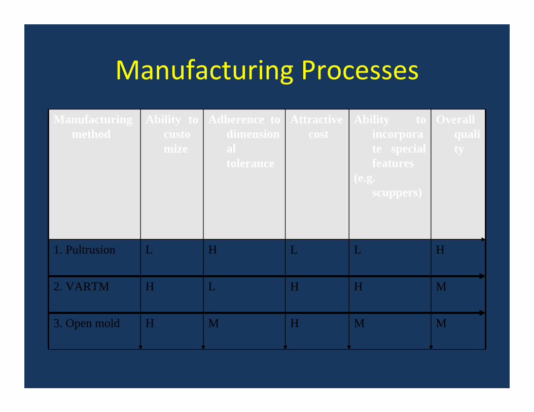
Manufacturing Processes
Manufacturing method
Ability to customize
Adherence to dimensional tolerance
Attractive cost
Ability to incorporate special features
(e.g. scuppers)
Overall quality
1. Pultrusion L H L L H
2. VARTM H L H H M
3. Open mold H M H M M

Manufacturing Processes
Pultrusion


Martin Marietta Composites
7 5/8” deep

Creative Pultrusions

Bedford Plastics Inc.
Prodeck 8
Prodeck 4

Strongwell

Kansas Structural Composites, Inc.

Hardcore Composites

Zell Comp

Composite Advantage
• Solid laminates or sandwich construction with fiberglass skins surrounding a fiber‐reinforced‐foam core

Trend toward Hybrids

Hybrids
• Amjad Aref’s hybrid deck, University at Buffalo
• Erie County’s Australian superstructure
• Niagara County’s timber‐FRP‐concrete
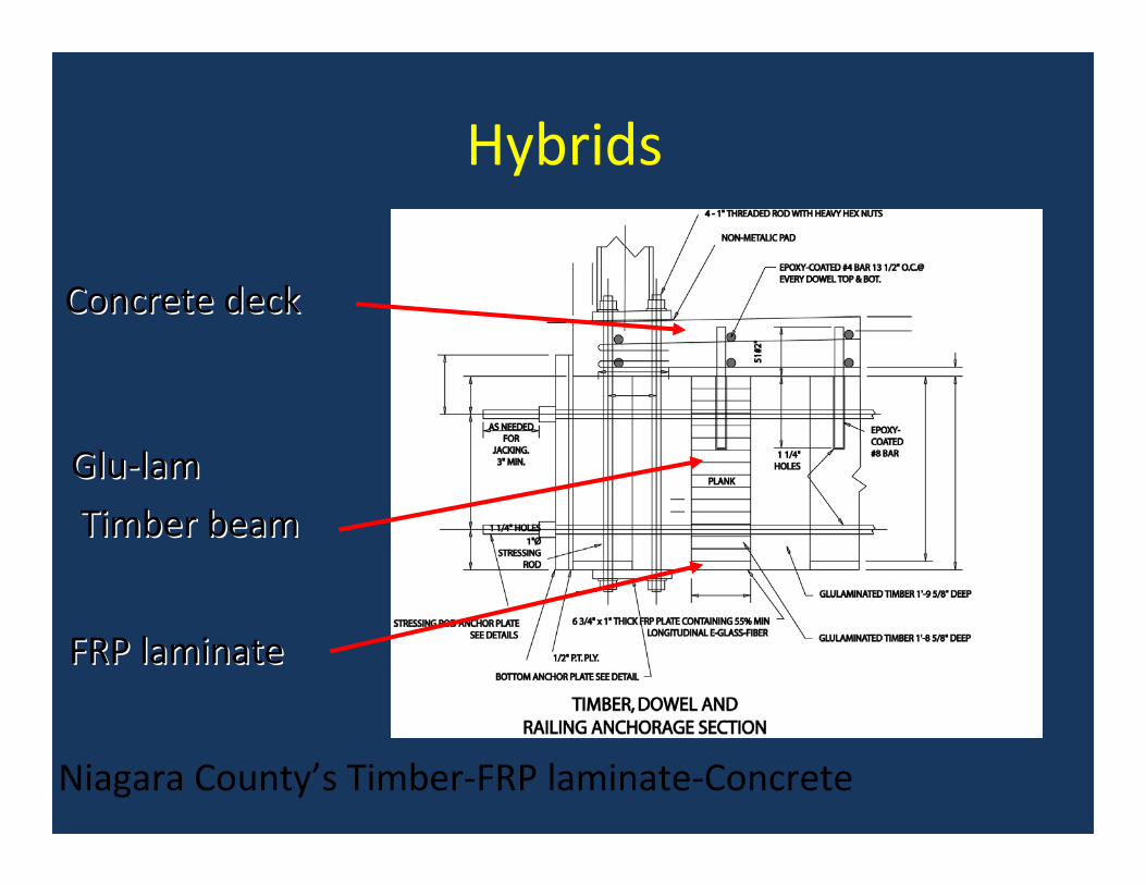
Hybrids
Niagara County’s Timber‐FRP laminate‐Concrete
GluGlu‐‐lamlam
Timber beamTimber beam
FRP laminateFRP laminate
Concrete deckConcrete deck

Hybrids
University at Buffalo’s Hybrid deck conducted by Prof. Amjad Aref(development sponsored by NYSDOT)

Hybrids65 MPa Concrete
Webs built up from 100 x 100 Pultrusions
GFRP Tensile Flange
Neutral Axis
2.1m
Erie County Erie County –– Australian Hybrid SuperstructureAustralian Hybrid Superstructure

Survey

Information Collected
• 68% used IBRC or other special funding
• ½ the projects were new construction
• FRP decks were attached to steel stringers (95%), concrete girders, FRP beams
• Design live load HS‐20 or HS‐25 + impact
• Largest deck area = 11,970 SF
• Highest traffic volume = 30,000 vpd

Deck Weight
020406080
100120140160180200
psf
Old Conc. Fill-Grid
Grid FRP 4"
Deck Type

Deck Cost
Material Cost Installed
8” deck $65-75 / sf $70-85 / sf
4-5” deck $35-60 / sf $45-70 /sf

Cost / SF
$0
$20
$40
$60
$80
$100
$120
$140
Bennetts Schroon Dyke LaChein
$ / SFInstalled
Projects with FRP Deck on Steel

Best Applications

Replace Heavy Decks
Inventory OperatingHS 12(22 Tons)
HS 18(33 Tons)
Inventory OperatingHS 23(42 Tons)
HS 34(61 Tons)
Before
After

Replace Light Decks
South Broad Street over Dyke Creek, Wellsville, NY Oct. 2000 Hardcore Composites

Maintain Historic Structures
NY Route 418 over Schroon River, Warrensburg, NY Nov. 2000Martin Marietta Composites

Build ‘em Fast
Accelerated Accelerated bridge bridge construction in construction in high traffic areashigh traffic areasenhances enhances safetysafety
Rte. 248 over Bennetts CreekRexville, NY Sept. 1998
Hardcore Composites

D‐I‐Y Bridges
LaChein BridgeMonroe, WV 2002Bedford Reinforced Plastics
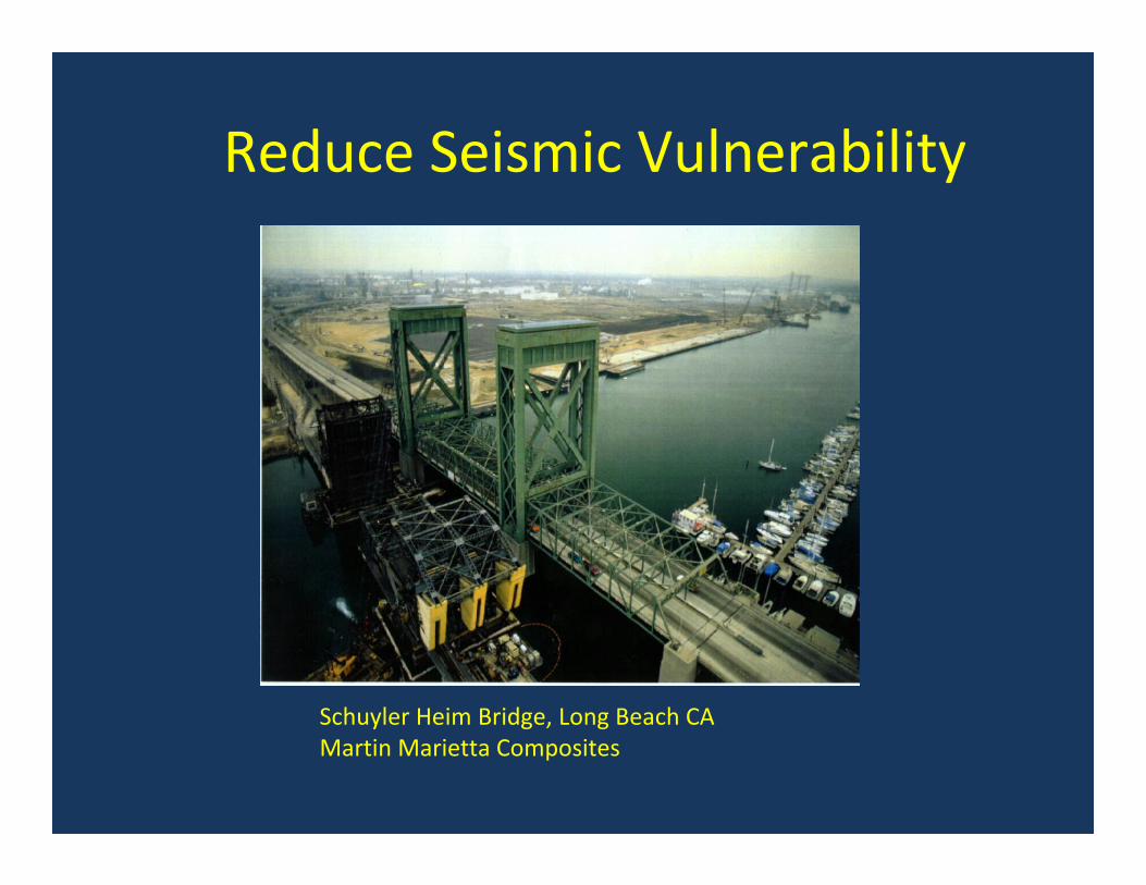
Reduce Seismic Vulnerability
Schuyler Heim Bridge, Long Beach CAMartin Marietta Composites

Moveable Bridges
Lewis & Clark Bridge, ORMartin Marietta Composites
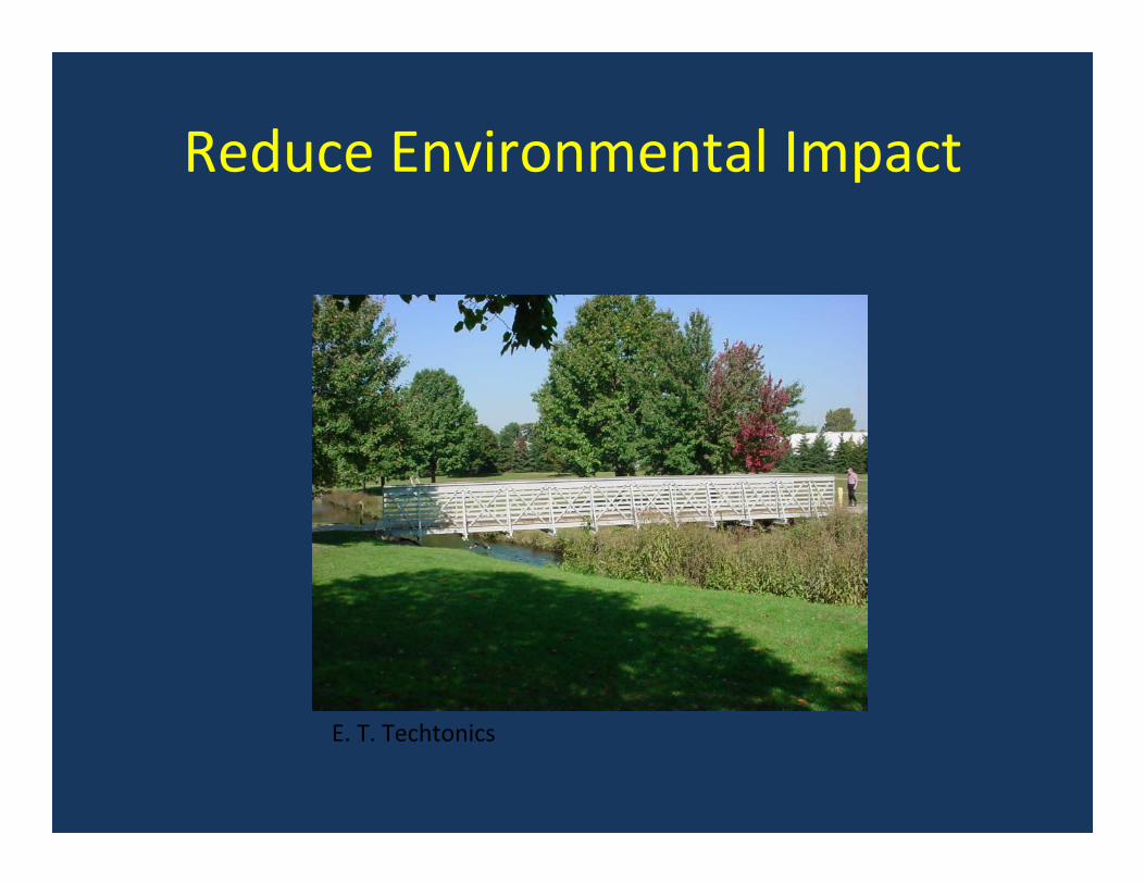
Reduce Environmental Impact
E. T. Techtonics

Pedestrian Bridges
1. 300 +/‐ in USA
2. 80% by E.T.Techtonics, 20% by others
3. Bridge Cost ~ $60 / SF
4. Draft Guide Spec


OutlineI. FRP BasicsII. Civil Engineering Applications
– Rebar (ppt)– Seismic Retrofitting (go to)– Aerodynamic Improvement (go to)– Concrete Strengthening using sheet, rods, strips, plates
(Techniques for strengthening steel with FRP is still evolving)
• Beams• Columns Court St
– Overhead Sign Structure Repair (go to)– Culvert Relining (go to)
–Bridge Decks Bentley–Bridge Superstructures New Oregon PR‐139
III. Handouts & References (go to)


TESTING,INSPECTION, &STRUCTURAL HEALTH MONITORING

Structural Health Monitoring (SHM)
• The importance of SHM is becoming more apparent as our older bridges are kept in service longer
• It is easy to incorporate sensors in FRP at the time of manufacture (e.g. fiber optic strain sensors)

Inspection
• What to look for? (integrity of joints and connections, water intrusion, debonding, delaminating)
• Infrared thermography as a tool
• Load testing
• Tap test
• NCHRP Project 10‐64 Report 564 “Field Inspection of In‐Service FRP Bridge Decks”
Video 248 debonding of bottom faceskinVideo 240 debonding of top faceskin

Infrared Thermography NY248/Bennetts Cr

POTENTIAL PROBLEMS

Wearing Surface Cracking & DebondingNY367 / Bentley Cr

Wearing Surface Cracking

Wearing Surface Debonding

Wearing Surface Debonding NY367/Bentley March 2009

Thermal Incompatibility

Wearing Surface Debonding(from Concrete)
•Proper surface preparation is essential•Extremely dry surface needed

Tap Test of Bottom FaceskinNY248 / Bennetts Cr
Mark’s tap test

Tap Test of Epoxy Injection Repair

De‐bonded Sandwich Sectionand Water Intake
Video 1 2 3 4
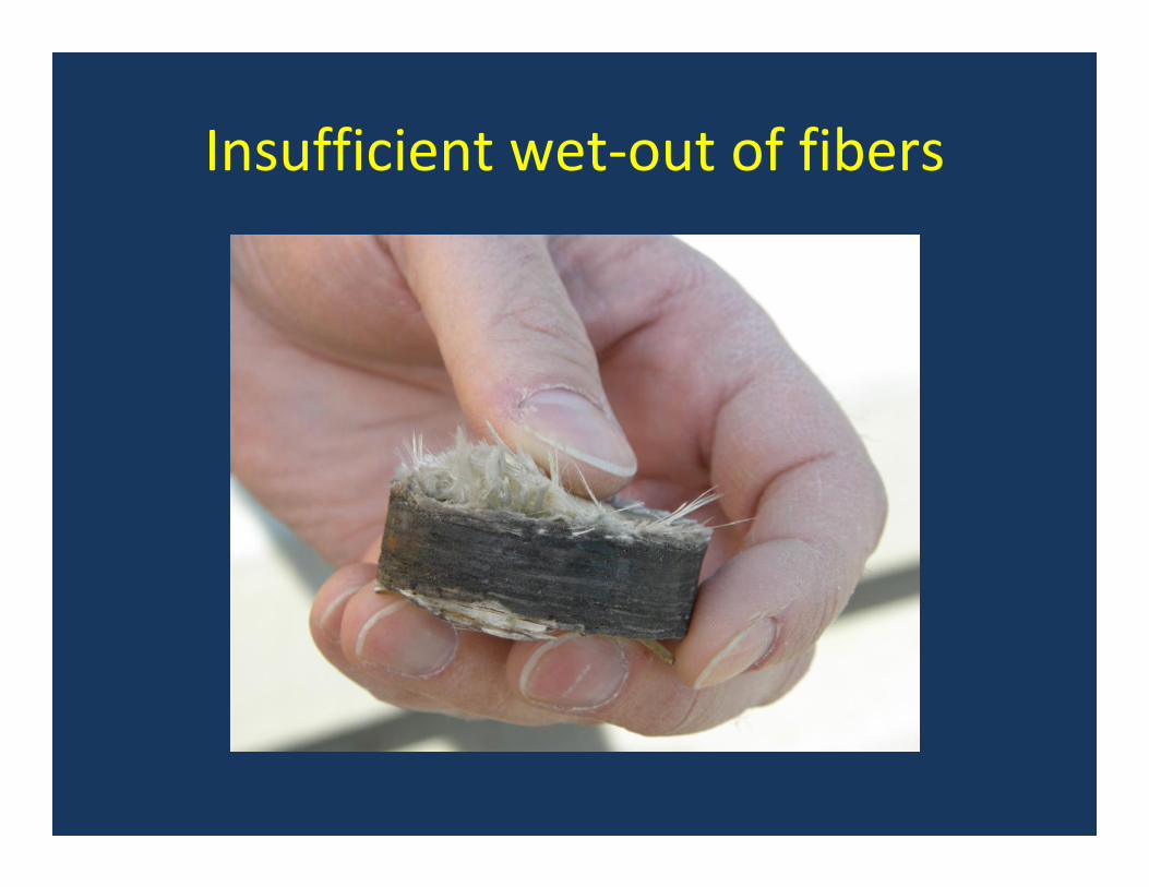
Insufficient wet‐out of fibers


RESOURCES

Resources
FHWA Virtual Team web siteNCHRP project reportsDOT’s web sitesDOT research reportsDOT project summaries (e.g. NY, WV)Conference proceedings (e.g. WV)ASCE JournalOther trade journals

Resources
1. FHWA FRP Virtual Team web site2. WVU biennial conference and past
proceedings)3. NYSDOT’s research reports, e.g. wearing
surfaces for FRP decks4. WV and NYS project summaries5. Former MDA project list6. Summary paper for TRB Int’l Br Conf (IBEC‐
0020)

ResourcesFHWA
Louis N. Triandafilou, P.E.
Team Leader, FRP Virtual Team
Federal Highway Administration
Phone: (410) 962‐3648
Fax: (410) 962‐4586
Email: [email protected]

ResourcesSyracuse Maintenance Manual
Guide for Maintenance and Rehabilitation of Concrete Bridge Components with FRP Composites – Research into Practice
Riyad S. Aboutaha, PhD., FACISyracuse University

ResourcesReinforced Plastics “decks & SS summary”
Reinforced Plastics, Elsevier Ltd.
Jerome O’Connor. PE, F,ASCEUniversity at Buffalo

Resources(list for decks & superstructures)
FRP Deck Suppliers
http://www.fhwa.dot.gov/bridge/frp/decksupl.htm
FRP Completed Projects
http://www.fhwa.dot.gov/bridge/frp/deckproj.htm

ResourcesACMA
John Busel,
Director , Composites Growth InitiativeAmerican Composites Manufacturers Association
(703) 525‐[email protected]

ResourcesACI‐440
http://www.concrete.org/COMMITTEES/committeehome.asp?committee_code=0000440‐00
• 440.1R‐06: Guide for the Design and Construction of Structural Concrete Reinforced with FRP Bars • 440.2R‐08: Guide for the Design and Construction of Externally Bonded FRP Systems for
Strengthening Concrete Structures • 440.3R‐04: Guide Test Methods for Fiber‐Reinforced Polymers (FRPs) for Reinforcing or Strengthening
Concrete Structures • 440.4R‐04: Prestressing Concrete Structures with FRP Tendons • 440.5‐08: Specification for Construction with Fiber‐Reinforced Polymer Reinforcing Bars • 440.5M‐08: Specification for Construction with Fiber‐Reinforced Polymer Reinforcing Bars (Metric) • 440.6‐08: Specification for Carbon and Glass Fiber‐Reinforced Polymer Bar Materials for Concrete
Reinforcement • 440.6M‐08: Specification for Carbon and Glass Fiber‐Reinforced Polymer Bar Materials for Concrete
Reinforcement (Metric) • 440R‐07: Report on Fiber‐Reinforced Polymer (FRP) Reinforcement for Concrete Structures • SP‐215: Field Applications of FRP Reinforcement: Case Studies • SP‐245CD: (CD‐ROM ) Case Histories and Use of FRP for Prestressing Applications • SP‐257CD: (CD‐ROM) FRP Stay‐In‐Place Forms for Concrete Structures • SP‐258CD: (CD‐ROM) Seismic Strengthening of Concrete Buildings Using FRP Composites

ResourcesAdditional
• NCHRP 04‐27 Application of Advanced Composites to the Highway Infrastructure: Strategic Plan
• NCHRP 10‐64 Field Inspection of In‐service FRP Bridge Decks (University of Wisconsin, Madison)
• FHWA DTFH61‐00‐C‐00021,22 Acceptance Test Specifications for FRP Bridge Decks and Superstructures (WVU & Georgia Tech)
• http://www.fhwa.dot.gov/bridge/frp/deckprac.htm

ResourcesHandouts
• New Oregon Road trifold brochure• Sample column wrap design• Reinforced Plastics ‘decks & superstructures’
article

Jerome S. OJerome S. O’’Connor, P.E. F, ASCEConnor, P.E. F, ASCE
[email protected]@buffalo.edu
(716) 645(716) 645‐‐51555155