ft flexitest™ family product guide
TRANSCRIPT
— PRODUC T GUIDE
FT Flexitest™ FamilyFT-1, FT-1F, FT-1X, FT-14, FT-14D, FT-19R, FT-19RX, FT-19RS, FT-22RS, test plugs, and accessories

2 F T F LE X ITE S T ™ S W ITCH E S TH ER E IS N O EQ U I VA L ENT
—With more than 50 years of experience, ABB is the test switch manufacturer with the largest installed base in North America. ABB introduced the FT switch and continues to be the leader in innovation. ABB now incorporates new ergonomic separate source test plugs, the FT-14 Digital FlexitestTM test switch, and FT cover shields to make testing safer, faster, and easier. In addition, ABB now offers a reverse current shorting pole option for special applications.
3
— Table of contents
05 1. Features and application 1.1 Features 1.2 Application
06– 09 2. The most complete family of test switches 2.1 FT-1 2.2 FT-1F 2.3 FT-1X 2.4 FT-14 2.5 FT-19R and FT-19RX 2.6 FT-19RS 2.7 FT-22RS 2.8 FT-14D
11 3. Advantages 3.1 Safe and convenient 3.2 Fast and reliable 3.3 Maximum flexibility 3.4 Security 3.5 Quality 3.6 Technical and application engineering support
12 4. Specifications 4.1 Certifications 4.2 Ratings 4.3 Mounting 4.4 Construction 4.5 Cover 4.6 Poles 4.6.1 Potential poles 4.6.2 Current poles 4.7 Switch handles 4.8 Terminal connections 4.9 Switch arrangement
4 F T F LE X ITE S T ™ S W ITCH E S TH ER E IS N O EQ U I VA L ENT
— Table of contents
18 5. Test plugs 5.1 In-services series test plugs 5.2 Individual current circuit test plug 5.3 Individual current circuit test plug with open CT protection 5.4 Separate source test plug 5.5 Flexitest test kit
20 6. FT Flexitest switches ordering information 6.1 FT-1, FT-1F and FT-1X switches 6.1.1 Terminal connections 6.1.2 Cover 6.1.3 Depth 6.1.4 Front connected 6.2 FT-14 6.2.1 Terminal connections 6.2.2 Cover 6.3 FT-19 and FT-22 test switch assemblies 6.3.1 Terminal connections 6.3.2 Panel height 6.3.3 Panel color and material 6.3.4 Flexitest switch code numbers (positions A, B, and C 6.3.5 Switches replacement 6.3.6 Cover 6.3.7 Additional features
33 7. Test plugs & accessories - ordering information
36 8. FT switch covers
40 9. Warranty

5
With more than 50 years of experience, ABB is the test switch manufacturer with the largest installed base in North America. ABB’s Flexitest test switch’s perfected design offers the highest quality, leaving nothing to chance. ABB Flexitest is the original FT - there is no equivalent.
1.1 Features• Clear covers that allow for easier visual check
on switch status• Colored switch handles to simply identify
circuits• Rear extended switches for easier, faster
access to wiring points• 14-pole and 19” wide rack mounted test
switches (FT-14 and FT-19R) to save space and installation time
• Patented 3-D white numbering on the rear of the test switch which allows for easier identification of poles
• Comprehensive family of test plugs including SafePlugTM – individual current test plug with open CT protection
• Online configurator to create and easily order your own, customized switch - spine.abb.com/ftswitch
• FT-1 and FT-14 meet Ingress Protection IP41 for protection against dripping water from the front with shallow clear and black covers installed. FT-1 and FT-14 meet Ingress Protection IP2X for finger safety at the product rear
• FT-1 and FT-14 are RoHS compliant
—FT FlexitestTM familyFeatures and application
1.2 Application ABB Flexitest™ switches, types FT-1 (10 pole, rear connected), FT-1F (10 pole, front connected), FT-1X (10 pole, extended terminals, rear connected), FT-14 (14 pole, rear connected), and associated Test Plugs, provide a safe, simple, fast and reliable method to isolate, test, and service installed equipment without disturbing the power system. FT-14D is a new test switch solution for digital switchgear using current and voltage sensors. The FT-14D switch ties to cutting-edge digital strategies by allowing customers to integrate current and voltage sensors within digital switchgear and Relion® protective relays.
FT-19R, FT-19RX, FT-19RS, and FT-22RS Flexitest switch assemblies for rack and switchboard mounting also permit convenient isolation of switchboard relays, meters, and instruments allowing quick and easy multi-circuit testing by any conventional test method. These assemblies utilize FT-1 and/or FT-14 switches, depending on customer requirements.

6 F T F LE X ITE S T ™ S W ITCH E S TH ER E IS N O EQ U I VA L ENT
—The most complete family of test switches
2.1. FT-1 Standard 10 pole, rear connected test switch. 2.2. FT-1F Surface mount switch allows the user to make the same connections as with FT-1 but on the front of the switch.
2.3. FT-1X Extended length test switch brings the rear terminal connections to the same depth as most panel mounted protective relays and equipment for easier and faster access to wiring points. Length extension of 8 inches or 10 inches depth is available.
2.4. FT-14 Provides the same features and reliability as FT-1 but with a maximum of 14 individual poles. Although supplying 40 percent more capacity than the FT-1, the FT-14 only requires 18 percent more space. 2.5. FT-19R and FT-19RX assemblies accommodate up to three FT-1 switches mounted on a 19” wide, and two-rack unit (2RU), three-rack unit (3RU), or four-rack unit (4RU) high panel suitable for rack or switchboard mounting. These assemblies can be ordered with a full-length clear cover (standard), or optional full-length black, individual black or clear covers.
FT-19RX extends the rear terminals of the FT-1 switches to the same depth as most 19” rack mounted equipment thereby providing improved access to the rear terminals. FT-19RX two-rack unit assemblies (2RU) allow the user to mount protective relays or other equipment in the racks directly above and below the FT-19RX, optimizing the space in the rack and reducing the amount of wire required.
—FT-19R 2RU with full length clear cover
—FT-1
—FT-1F
—FT-1X
—FT-14
FT FlexitestTM family

7
2.6 FT-19RS assemblies consist of up to two FT-1 switches, two FT-14 switches, or the combination of one FT-1 and one FT-14 switch mounted on a 19” wide, and two-rack unit (2RU), three-rack unit (3RU), or four-rack unit (4RU) high panel suitable for rack or switchboard mounting. Any combination of FT-1 or FT-14 switches styles may be selected with individual black or clear covers. Non-ABB equipment is not included with the assembly (see FT-19RS picture).
2.7 FT-22RS assemblies consists of up to three FT-1 or two FT-14 switches mounted on a 22” wide, two-rack unit (2RU), three-rack unit (3RU), or four-rack unit (4RU) high mounting panel suitable for rack or switchboard mounting. Any combination of FT-1 or FT-14 switches styles may be selected with individual black or clear covers. Mounting panels for these assemblies can be of steel or aluminum. Steel panels are commonly available in ANSI 61 gray, ANSI 70 gray, and RAL7035 gray, beige, light sandalwood, thunder blue, black, and white; although panel color or finish, as well as panel height, can be customized to meet the user’s necessities. The three rack unit (3RU) assembly also allows switches to be positioned off-center, in either low or high upper mounting positions in the rack panel, allowing room for special label requirements.
—FT-19 3RU lockable version
—FT-19R 3RU with special customer labels
—FT-22RS
—FT-19RX 3RU with full length clear cover
—FT-19RS
FT FlexitestTM family

8 F T F LE X ITE S T ™ S W ITCH E S TH ER E IS N O EQ U I VA L ENT

9
—FT-14D Digital Test SwitchRevolutionary technology to make testing safer, faster, and easier
2.8 FT-14D is used for testing, commissioning, and metering of relays, and current and voltage sensors used in digital switchgear.
FT-14D incorporates a passive electronic module on the rear with RJ45 connection to the Relion® relays with low-energy voltage and current sensor inputs. The FT-14D maintains the same front interface as the standard FT-14 Flexitest™ switch. The FT-14D meets ANSI/ IEEE Standard C37.90, UL and is ESD proven. See page 23 for style number information.
TestingFor testing purposes, use the FT-14D in conjunction with two accessories: the FT-14 separate source test plug and the FT-14D test harness (figure C).
First, connect the FT-14D test harness RJ45 connectors to an interface adapter that is plugged into the protection relay test equipment. Then, insert the banana plugs into the FT-14 separate source test plug. Last, insert the FT-14 separate source test plug into the FT-14D by placing the switch blades in open position. This procedure disconnects the low-energy current and voltage sensors from the relay, and allows testing to be performed with the relay test equipment.
CautionAll relays and test equipment must be properly grounded.
WarningConnections to all equipment should be made using standard and safe connection practices. Due to the low-energy sensing during system operation, it is important not to touch the open or closed FT-14D switchjaw terminals since relay misoperation can occur. Therefore, during testing and maintenance, it is also recommended the relay trip circuit be disconnected first as a precaution.
Passive electronic module
Lamicoid labels included on each handle
No CT shorting required
Standard screw type connections
Connections to the Relion® relay and sensors
—a.
—b.
—c.
—Figure a. Front view FT-14D based upon the FT-14 interface Figure b. Rear view FT-14D adds electronic module on the back with RJ45 connectors Figure c. FT-14D test harness and FT-14D separate source test plug
RJ45 connector connects to relay test equipment interface

10 F T F LE X ITE S T ™ S W ITCH E S TH ER E IS N O EQ U I VA L ENT
11
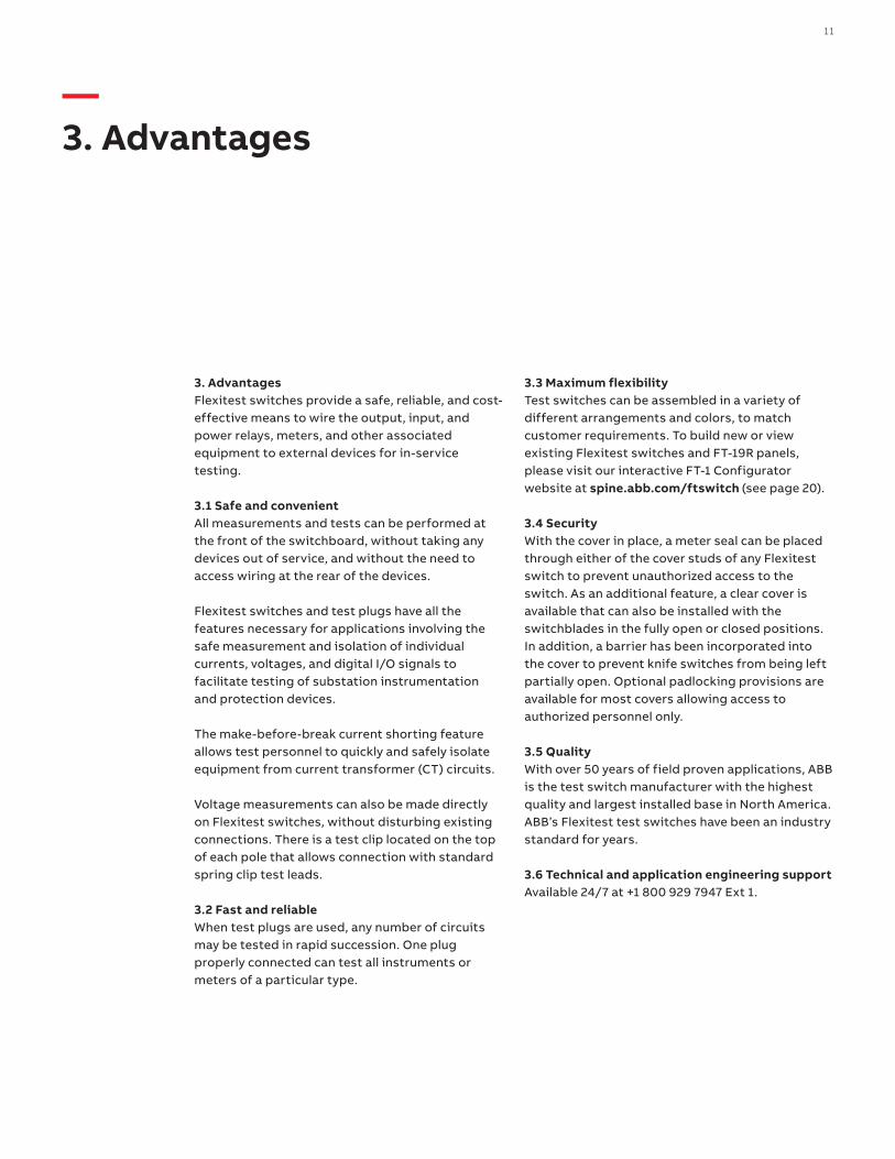
3. Advantages Flexitest switches provide a safe, reliable, and cost-effective means to wire the output, input, and power relays, meters, and other associated equipment to external devices for in-service testing.
3.1 Safe and convenientAll measurements and tests can be performed at the front of the switchboard, without taking any devices out of service, and without the need to access wiring at the rear of the devices.
Flexitest switches and test plugs have all the features necessary for applications involving the safe measurement and isolation of individual currents, voltages, and digital I/O signals to facilitate testing of substation instrumentation and protection devices.
The make-before-break current shorting feature allows test personnel to quickly and safely isolate equipment from current transformer (CT) circuits.
Voltage measurements can also be made directly on Flexitest switches, without disturbing existing connections. There is a test clip located on the top of each pole that allows connection with standard spring clip test leads.
3.2 Fast and reliableWhen test plugs are used, any number of circuits may be tested in rapid succession. One plug properly connected can test all instruments or meters of a particular type.
3.3 Maximum flexibilityTest switches can be assembled in a variety of different arrangements and colors, to match customer requirements. To build new or view existing Flexitest switches and FT-19R panels, please visit our interactive FT-1 Configurator website at spine.abb.com/ftswitch (see page 20).
3.4 SecurityWith the cover in place, a meter seal can be placed through either of the cover studs of any Flexitest switch to prevent unauthorized access to the switch. As an additional feature, a clear cover is available that can also be installed with the switchblades in the fully open or closed positions. In addition, a barrier has been incorporated into the cover to prevent knife switches from being left partially open. Optional padlocking provisions are available for most covers allowing access to authorized personnel only.
3.5 QualityWith over 50 years of field proven applications, ABB is the test switch manufacturer with the highest quality and largest installed base in North America. ABB’s Flexitest test switches have been an industry standard for years.
3.6 Technical and application engineering supportAvailable 24/7 at +1 800 929 7947 Ext 1.
—3. Advantages
12 F T F LE X ITE S T ™ S W ITCH E S TH ER E IS N O EQ U I VA L ENT
4.1 CertificationsAll Flexitest switches meet or exceed all requirements of ANSI/IEEE Standard C37.90. Class 1E switches meet IEEE C37.98, C37.105, 323-1983 and 344-1987 Standards.
UL and CUL file number E504331, and Class 1E certification are available for most test switches. Contact your ABB representative for more details.
FT-1 and FT-14 meet Ingress Protection IP41 for the front of the product with shallow clear and black covers installed. FT-1 and FT-14 meet Ingress Protection IP2X for the rear.
FT-1 and FT-14 are RoHS compliant.
4.2 RatingsAll Flexitest switches are rated at 600 Volts AC or DC and 30 Amps.
4.3 MountingThe FT-1, FT-14, and FT-1X switches are designed for semi-flush mounting on the front of switchboard panels, facilitating inspection and accessibility. The FT-1F is designed for surface mounting and can also be mounted on a unistrut with the use of a unistrut adapter plate. Refer to figures 08 to 11 on page 41-44 for the specific outline and drilling plan information of each switch.
The FT-19R, FT-19RX, and FT-19RS are designed for mounting on 19-inch rack structures or conventional panels. The FT-22RS are designed for mounting on 22-inch rack structures. Outline, drilling plan, and switch dimensions are shown on page 45-51.
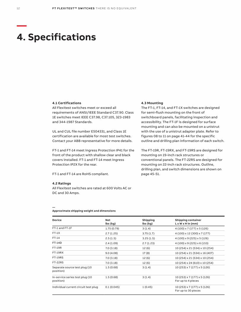
—Approximate shipping weight and dimensions
Device Net lbs (kg)
Shipping lbs (kg)
Shipping container L x W x H in (mm)
FT-1 and FT-1F 1.75 (0.79) 3 (1.4) 4 (100) x 7 (177) x 5 (126)
FT-1X 2.7 (1.25) 3.75 (1.7) 4 (100) x 12 (300) x 7 (177)
FT-14 2.5 (1.5) 3.25 (1.5) 4 (100) x 9 (225) x 5 (126)
FT-14D 2.4 (1.09) 2.7 (1.23) 4 (100) x 9 (225) x 6 (153)
FT-19R 7.0 (3.18) 12 (6) 10 (254) x 21 (534) x 10 (254)
FT-19RX 9.0 (4.08) 17 (8) 10 (254) x 21 (534) x 16 (407)
FT-19RS 7.0 (3.18) 12 (6) 10 (254) x 21 (534) x 10 (254)
FT-22RS 7.0 (3.18) 12 (6) 10 (254) x 24 (610) x 10 (254)
Separate source test plug (10 position)
1.5 (0.68) 3 (1.4) 10 (253) x 7 (177) x 5 (126)
In-service series test plug (10 position)
1.5 (0.68) 3 (1.4) 10 (253) x 7 (177) x 5 (126)For up to 4 pieces
Individual current circuit test plug 0.1 (0.045) 1 (0.45) 10 (253) x 7 (177) x 5 (126)For up to 30 pieces
—4. Specifications
13
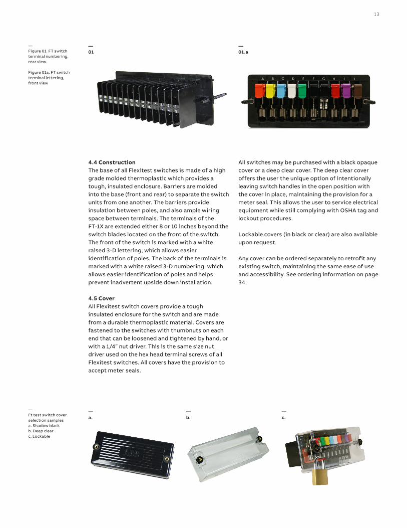
4.4 ConstructionThe base of all Flexitest switches is made of a high grade molded thermoplastic which provides a tough, insulated enclosure. Barriers are molded into the base (front and rear) to separate the switch units from one another. The barriers provide insulation between poles, and also ample wiring space between terminals. The terminals of the FT-1X are extended either 8 or 10 inches beyond the switch blades located on the front of the switch. The front of the switch is marked with a white raised 3-D lettering, which allows easier identification of poles. The back of the terminals is marked with a white raised 3-D numbering, which allows easier identification of poles and helps prevent inadvertent upside down installation.
4.5 CoverAll Flexitest switch covers provide a tough insulated enclosure for the switch and are made from a durable thermoplastic material. Covers are fastened to the switches with thumbnuts on each end that can be loosened and tightened by hand, or with a 1/4” nut driver. This is the same size nut driver used on the hex head terminal screws of all Flexitest switches. All covers have the provision to accept meter seals.
All switches may be purchased with a black opaque cover or a deep clear cover. The deep clear cover offers the user the unique option of intentionally leaving switch handles in the open position with the cover in place, maintaining the provision for a meter seal. This allows the user to service electrical equipment while still complying with OSHA tag and lockout procedures.
Lockable covers (in black or clear) are also available upon request.
Any cover can be ordered separately to retrofit any existing switch, maintaining the same ease of use and accessibility. See ordering information on page 34.
—Ft test switch cover selection samples a. Shadow black b. Deep clear c. Lockable
—Figure 01. FT switch terminal numbering, rear view. Figure 01a. FT switch terminal lettering, front view
—01
—01.a
—a.
—b.
—c.

14 F T F LE X ITE S T ™ S W ITCH E S TH ER E IS N O EQ U I VA L ENT
4.6 PolesFT-1, FT-1F, and FT-1X switches are available in combinations of 1 to a maximum of 10 individual poles or switch units. FT-14 switches are available in combinations of 1 to a maximum of 14 poles or switch units. Each pole is identified by a letter (A to J or A to N) visible along the top of the base from left to right (front view).
Individual pole designations are used to identify each pole according to its type or function. In order to develop a complete switch arrangement, pole designations should be listed sequentially from left to right to account for every pole position on the switch. Unused poles are identified by the letter X.
Each individual pole is of a knife blade type. There are two different types of poles, potential and current.
For quick, easy, user friendly configuration of flexitest switches, please visit spine.abb.com/ftswitch.
4.6.1 Potential polesPotential poles (P) are configured as single, non-shorting knife blades for use in potential, trip, or control circuits. P designates a potential, trip, or control circuit with a black handle. Potential poles with other color handles are available by replacing the “P” with the appropriate designation per chart on page 15.
Each potential pole can also be described with two characters (P1 to P9). P indicates potential and the second character is a numeric color code for the switch handle.
4.6.2 Current polesCurrent poles are typically configured in sets of two (C-C), for use with current circuits, and consist of a current test jack, a shorting spring, a shorting blade, and a non-shorting blade (see Figure 2). The positions of the short circuit springs are always visible from the front of the switch.
C designates a single current circuit, non-shorting pole, with a current test jack and a black handle. Current poles with other color handles are available by replacing the “C” with the appropriate designation per chart on page 15.
Each current pole can also be described with two characters (C1 to C9). C indicates current and the second character is a numeric color code for the switch handle.
Current poles typically span more than one pole position. Pole designations C-C, C-C-C, C-C-C-C and C-C-C-C-C indicate current shorting poles (make-before-break) with black handles. Note that any color handle may be selected for any pole position by using the appropriate pole designation, ex: 5-R or C-9-7 (alternately C5-C2 or C1-C9-C7).
—Figure 02. Blade assembly of 2 position current poles
Switchjaw Test clip
Shorting blade
CT shorting spring
Non-shorting spring
Current test jack
Test switch cam makes with the CT shorting spring before the knife blade breaks from the switchjaw
—02
Visual FT switch disconnect“make-before-break” operation
CT reversed shorting spring
15
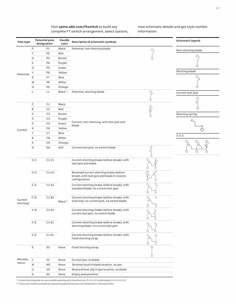
Pole typePotential pole
designationHandle
colorDescription & schematic symbols
Potential
P P1 Black Potential, non-shorting blade
T P2 Red
H P3 Brown
V P4 Purple
G P5 Green
Y P6 Yellow
Z P7 Blue
W P8 White
O P9 Orange
L L1 Black †† Potential, shorting blade
Current
C C1 Black
Current, non-shorting, with test jack and blade
R C2 Red
3 C3 Brown
4 C4 Purple
5 C5 Green
6 C6 Yellow
7 C7 Blue
8 C8 White
9 C9 Orange
D D0 N/A Current test jack, no switch blade
Current shorting†
C-C C1-C1
Black ††
Current shorting (make-before-break), with test jack and blade
C+C C1+C1 Reversed current shorting (make-before-break), with test jack and blade in reverse configuration
C-A C1-A1 Current shorting (make-before-break), with standard blade, no current test jack
C-B C1-B1 Current shorting (make-before-break), with stud only, no current jack, no switch blade
C-D C1-D1 Current shorting (make-before-break), with current test jack, no switch blade
C-E C1-E1 Current shorting (make-before-break), with shorting blade, no current test jack
C-S C1-S1 Current shorting (make-before-break), with fixed shorting strap
Miscella-neous
S S0 None Fixed shorting strap
J J0 None Current jaw, no blade
N N0 None Terminal stud in blade location, no jaw
U U0 None Stud and test clip in jaw location, no blade
X X0 None Empty pole position
Schematic legend
Non-shorting blade
Shorting blade
Current test jack
Shorting spring
C-C-C
Visit spine.abb.com/ftswitch to build any complete FT switch arrangement, select options,
view schematic details and get style number information.
† = Current shorting poles are also available spanning up to 5 positions (ex: C-C-C-C-C or alternately C1-C1-C1-C1-C1)†† = Every color handle is available by substituting appropriate pole color designation in desired location
16 F T F LE X ITE S T ™ S W ITCH E S TH ER E IS N O EQ U I VA L ENT
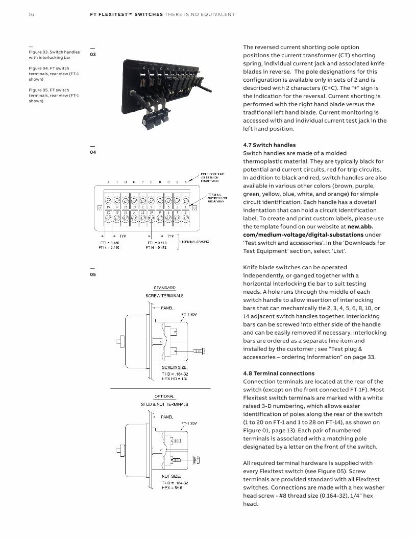
The reversed current shorting pole option positions the current transformer (CT) shorting spring, individual current jack and associated knife blades in reverse. The pole designations for this configuration is available only in sets of 2 and is described with 2 characters (C+C). The “+” sign is the indication for the reversal. Current shorting is performed with the right hand blade versus the traditional left hand blade. Current monitoring is accessed with and individual current test jack in the left hand position. 4.7 Switch handlesSwitch handles are made of a molded thermoplastic material. They are typically black for potential and current circuits, red for trip circuits. In addition to black and red, switch handles are also available in various other colors (brown, purple, green, yellow, blue, white, and orange) for simple circuit identification. Each handle has a dovetail indentation that can hold a circuit identification label. To create and print custom labels, please use the template found on our website at new.abb.com/medium-voltage/digital-substations under ‘Test switch and accessories’. In the ‘Downloads for Test Equipment’ section, select ‘List’.
Knife blade switches can be operated independently, or ganged together with a horizontal interlocking tie bar to suit testingneeds. A hole runs through the middle of each switch handle to allow insertion of interlocking bars that can mechanically tie 2, 3, 4, 5, 6, 8, 10, or 14 adjacent switch handles together. Interlocking bars can be screwed into either side of the handle and can be easily removed if necessary. Interlocking bars are ordered as a separate line item and installed by the customer ; see “Test plug & accessories – ordering information” on page 33.
4.8 Terminal connectionsConnection terminals are located at the rear of the switch (except on the front connected FT-1F). Most Flexitest switch terminals are marked with a white raised 3-D numbering, which allows easier identification of poles along the rear of the switch (1 to 20 on FT-1 and 1 to 28 on FT-14), as shown on Figure 01, page 13). Each pair of numbered terminals is associated with a matching pole designated by a letter on the front of the switch. All required terminal hardware is supplied with every Flexitest switch (see Figure 05). Screw terminals are provided standard with all Flexitest switches. Connections are made with a hex washer head screw - #8 thread size (0.164-32), 1/4” hex head.
—Figure 03. Switch handles with interlocking bar
Figure 04. FT switch terminals, rear view (FT-1 shown) Figure 05. FT switch terminals, rear view (FT-1 shown)
—03
—04
—05
17
Stud and nut terminals are an optional feature. Connections are made with two washers and a nut. A special (5/16”) nut driver can be purchased from ABB to connect to stud terminals, see “Test plug & accessories - ordering information” on page 33. WarningConnections to ALL equipment should be made using standard and safe connection practices. Recommended maximum torque values for all FT switch terminals is 16 in-lbs. Exceeding this torque may result in damage to terminal threads. On extended versions of the FT switch (ex. FT-1X), exceeding maximum torque values may lead to loosening of internal hardware. Even number terminals (bottom row) of Flexitest switches should be connected to voltage transformers and current transformers, while odd number terminals (top row) should be connected to equipment that is to be isolated, such as meters and relays. Max Lug size = Yellow 10-12 AWG. Ring terminal. Recommended lug size for PT’s is 12 AWG and 10 AWG for CT’s.
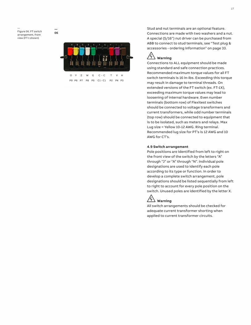
4.9 Switch arrangementPole positions are identified from left to right on the front view of the switch by the letters “A” through “J” or “A” through “N”. Individual pole designations are used to identify each pole according to its type or function. In order to develop a complete switch arrangement, pole designations should be listed sequentially from left to right to account for every pole position on the switch. Unused poles are identified by the letter X. WarningAll switch arrangements should be checked for adequate current transformer shorting when applied to current transformer circuits.
—Figure 06. FT switch arrangement, front view (FT-1 shown)
—06
O Y Z W G C - C T V H
P9 P6 P7 P8 P5 C1 - C1 P2 P4 P3

18 F T F LE X ITE S T ™ S W ITCH E S TH ER E IS N O EQ U I VA L ENT
5. Test plugsTest plugs used in conjunction with Flexitest switches enable easy measurement, calibration, verification and maintenance of relays, meters and instruments.
5.1 In-service series test plugThe “In-service” series test plug with a maximum of 10 positions is designed to match the pole configurations of specific styles of FT Flexitest devices (either FT-1, FT-1F, FT-1X switches or FT case relays).
This test plug is typically used to connect devices measuring the currents and voltages being applied to the switchboard relays, meters and instruments without interrupting or short-circuiting the circuit. Only current test switches with a current test jack must be opened before inserting the series test plug. Connections to the test plug must be made before inserting the test plug into a Flexitest switch or relay.
—5. Test plugs
Not every switch or relay pole configuration is suitable to accept an in-service series test plug. For available styles, see table 1, FT-1 switch selection guide 1VAC397062-SG. You may also refer to your ABB representative or ABB FT-1 configurator at spine.abb.com/ftswitch.
WarningWhen using an in-service series test plug for current measurements, connections from the test plug to the measuring instruments must be made before inserting the test plug in place.
5.2 Individual current circuit test plugThis plug consists of two conducting strips separated by an insulating strip. The ammeter is connected to these strips by terminal screws and leads carried out through holes in the back of the insulated handle. (See figures b and d on page 18-19).
The standard test plug inserts into the current test jack with the red part of the handle facing up allowing the alignment nipple and tab to guide the connector into the test jack.
5.3 SafePlug with open CT protectionThe SafePlug is an individual current circuit test plug with open current transformer (CT) protection provides a safe, simple, fast, and reliable method to test and service installed equipment while reducing risks due to operator error, incorrect equipment settings, or deviation from correct test
—a.
—Figure 07. Safe plug with open CT protection
—a. In-service series test plug b. Individual current circuit test plug c. Left) New design - ergonomic separate source test plug; Right) Old design - standard separate source test plug d. Individual current circuit test plug inserted in Flexitest relay case e. Separate source test plug inserted into FT switch f. FT test kit
—b.
—c.
—07

19
procedures. Its design prevents shock hazards, outages, and erroneous meter readings all associated with open CTs. If a CT opens during operation, the test plug shorts the CT to protect the operator, typically within 100 microseconds or less (6/1000th of a cycle). At the same time a red LED provides visual indication of the fault.
WarningWhen using an in-service series test plug for current measurements, connections from the test plug to the measuring instruments must be made before inserting the test plug in place. 5.4 Separate source test plugBoth 10 position, FT-1 and 14 position, FT-14 separate source test plugs isolate the externalconnections from the relay or equipment undertest. The test plugs accept all common size bananaplugs, ring wire connectors, and spade lugs, and have a through hole for meter probe or wire connections. The separate source test plugs provide quick circuit testing by fitting into the stationary contact jaws of any matching Flexitest type FT case or switch.
5.4.1 Ergonomic separate source test plugThe 10 and 14 position Ergonomic separate source test plugs utilize an alignment boss at each end to connect with the FT-1 and FT-14 switch cover mounting posts respectively, for secure and accurate alignment. The ergonomic separate source test plug incorporates a handle for ease of insertion into the FT test switch. The separate source test plug 45 degree connector angle makes it easy to access and connect test leads at virtually any height. The separate source test plug incorporates a unique extended isolating barrier that prevents relay and power system misoperationby performing a secure break-before-make opera-tion when inserted or disconnected. The separate source test plug design connects the relay inputs
and outputs to a set of binding banana posts on the top of the test plug. An insulated barrier along the bottom of the blades isolates the relay circuits from external connections. Test circuits can then be connected to these binding posts, which are staggered for easy accessibility. Before inserting the separate source test plug into service, all switchblades must be placed in the full open posi-tion. In a Flexitest type FT case, the 10 position separate source test plug is inserted in the bottom switch jaw with the binding posts up and in the top test switch jaw with the binding posts down.
5.4.2 Standard separate source test plugThe 10 position Standard separate source test plug utilizes L-shaped test blades to ensure quick, accu-rate alignment between the test plug and the sta-tionary contact jaws. The Standard separate source test plug is recommended for testing electrome-chanical relays in the Flexitest type FT case.
Warning(10 position, FT-1 Standard separate source test plug): in order to prevent relay misoperation, do not insert or remove the 10 position separate source test plug while the test set leads are attached. Provision is made only on current poles with shorting springs to automatically short-circuit current transformer circuits when the knife switches are opened prior to inserting the test plug. 5.5 Flexitest test kitThe ABB Flexitest test kit comes with a convenient carrying case to hold your hand held meter, test plugs, patch cords, test clips, and test probes in neat order. Flexitest test kits can be ordered with your selected quantities of test plugs, safety patch cords, test clips, and test probes. Patch cords are highly durable and flexible. Contact your local ABB representative for a quotation. For more information see “Test Plugs & Accessories -Ordering Information” on pages 33-35.
—d.
—e.
—f.
20 F T F LE X ITE S T ™ S W ITCH E S TH ER E IS N O EQ U I VA L ENT
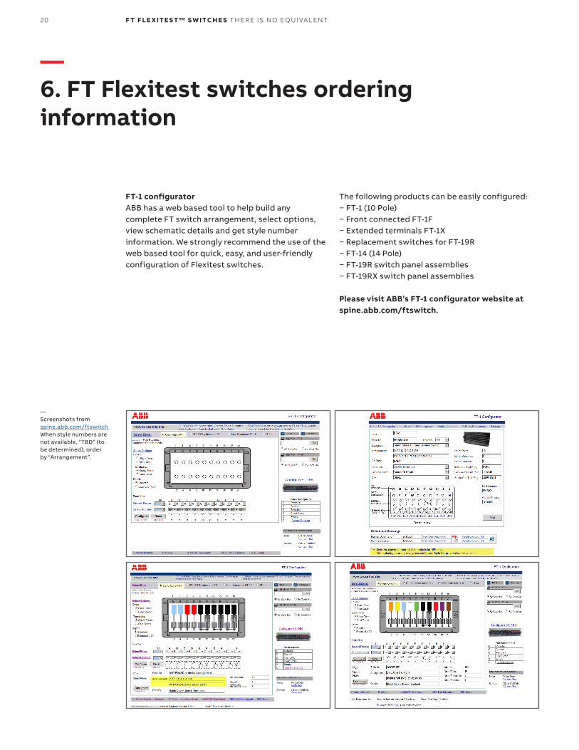
FT-1 configuratorABB has a web based tool to help build any complete FT switch arrangement, select options, view schematic details and get style number information. We strongly recommend the use of the web based tool for quick, easy, and user-friendly configuration of Flexitest switches.
—6. FT Flexitest switches ordering information
The following products can be easily configured:− FT-1 (10 Pole)− Front connected FT-1F− Extended terminals FT-1X− Replacement switches for FT-19R− FT-14 (14 Pole)− FT-19R switch panel assemblies− FT-19RX switch panel assemblies Please visit ABB’s FT-1 configurator website at spine.abb.com/ftswitch.
—Screenshots from spine.abb.com/ftswitch When style numbers are not available, “TBD” (to be determined), order by “Arrangement”.
21
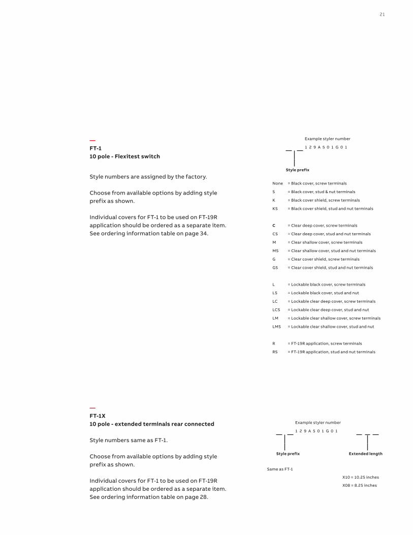
None = Black cover, screw terminals
S = Black cover, stud & nut terminals
K = Black cover shield, screw terminals
KS = Black cover shield, stud and nut terminals
C = Clear deep cover, screw terminals
CS = Clear deep cover, stud and nut terminals
M = Clear shallow cover, screw terminals
MS = Clear shallow cover, stud and nut terminals
G = Clear cover shield, screw terminals
GS = Clear cover shield, stud and nut terminals
L = Lockable black cover, screw terminals
LS = Lockable black cover, stud and nut
LC = Lockable clear deep cover, screw terminals
LCS = Lockable clear deep cover, stud and nut
LM = Lockable clear shallow cover, screw terminals
LMS = Lockable clear shallow cover, stud and nut
R = FT-19R application, screw terminals
RS = FT-19R application, stud and nut terminals
— FT-110 pole - Flexitest switch
Style numbers are assigned by the factory. Choose from available options by adding style prefix as shown. Individual covers for FT-1 to be used on FT-19R application should be ordered as a separate item. See ordering information table on page 34.
— FT-1X10 pole - extended terminals rear connected
Style numbers same as FT-1. Choose from available options by adding style prefix as shown. Individual covers for FT-1 to be used on FT-19R application should be ordered as a separate item. See ordering information table on page 28.
Same as FT-1
X10 = 10.25 inches
X08 = 8.25 inches
Example styler number
1 2 9 A 5 0 1 G 0 1
Style prefix
Example styler number
1 2 9 A 5 0 1 G 0 1
Style prefix Extended length

2222 F T F LE X ITE S T ™ S W ITCH E S TH ER E IS N O EQ U I VA L ENT
F = Black cover, screw terminals
FS = Black cover, stud & nut terminals
KF = Black cover shield, screw terminals
KSF = Black cover shield, stud & nut terminals
CF = Clear deep cover, screw terminals
CSF = Clear deep cover, stud and nut terminals
MF = Clear shallow cover, screw terminals
MSF = Clear shallow cover, stud and nut terminals
GF = Clear cover shield, screw terminals
GSF = Clear cover shield, stud and nut terminals
LF = Lockable black cover, screw terminals
LSF = Lockable black cover, stud and nut
LCF = Lockable clear deep cover, screw terminals
LCSF = Lockable clear deep cover, stud and nut
LMF = Lockable clear deep cover, screw terminals
LMSF = Lockable clear deep cover, stud and nut
— FT-1F10 pole - front connected
Style numbers are assigned by the factory. Choose from available options by adding style prefix as shown.
— FT-1414 pole - Flexitest switch
FT4 A 14 T 14 C N 4001
Base type:
FT4 = FT14
Depth
A= Standard depth (rear connected)
No. of poles:
01-14 = Total number of poles used
Terminals:
T = Standard screw terminals
S = Stud and nut terminals
No. of potentials:
00-14 = Total number of potential poles
Cover
C = Clear cover
B = Black cover
G = Clear cover shield
K = Black cover shield
M = Clear, shallow cover
L = Lockable clear cover
R = Lockable black cover
W = Lockable clear, shallow cover
N = None
Code no.:
4001-4999 = Unique code number assigned by the factory
Example styler number
1 2 9 A 5 0 1 G 0 1
Style prefix

23
— FT-14D14 pole Flexitest switch
FT4 D 14 T 14 M N 4779 - 01
Base type:
FT4 = FT14
Depth
D= Standard depth (rear connected)
No. of poles:
14 = Total number of poles used
Terminals:
T = Standard screw terminals
No. of potentials:
12-14 = Total number of potential poles
Cover
C = Clear cover
B = Black cover
G = Clear cover shield
K = Black cover shield
M = Clear, shallow cover
L = Lockable clear cover
R = Lockable black cover
W = Lockable clear, shallow cover
N = None
Code no.:
4779 - 01 = All potential blades, with lamicoid G01
4780 - 02 = 12 potential blades, 2 currents (Pos. 13&14), with lamicoid G02
FT-14D and cover options Standard style numbers
Clear shallow cover with potential terminals 13,14 FT4D14T14MN4779-01
Black cover with potential terminals 13, 14 FT4D14T14BN4779-01
Clear shallow cover with current terminals 13, 14 FT4D14T12MN4780-02
Black cover with current terminals 13, 14 FT4D14T12BN4780-02
FT-14D test harness Style no.
Quantity 3 (kit for 3 phase testing) 95A1159G01
Quantity 1 95A1159H01

2424 F T F LE X ITE S T ™ S W ITCH E S TH ER E IS N O EQ U I VA L ENT
6.1 FT-1, FT-1F and FT-1X switches are available in any combination of 1 to 10 poles. Each different configuration of poles is assigned a unique part number or style number by the factory. See ordering information chart for FT-1, FT-1X, and FT-1F on pages 21-22.
The standard FT-1 style number defines a unique pole configuration with black cover and screw terminals ex: 129A501G01. Adding a prefix and/or suffix to the standard style number allows the selection of options for FT-1 as well as the ability to create complete FT-1F and FT-1X style numbers.
Customers may also place an order by providing a complete switch arrangement definition as well as the selected options. ex: P X P C-C C-C C-C P (P1 X0 P1 C1-C1 C1-C1 C1-C1 P1), clear cover, screw terminals. For configurations -A or -E, the double character should be used.
6.1.1 Terminal connectionsAn optional FT-1 switch with stud and nut termination can be supplied at no additional charge. Style number prefix “S” is used for this option, ex: S129A501G01. For optional clear cover with stud and nut terminals use style number prefix “CS”, ex: CS129A501G01. See pages 21-22 for more ordering details.
6.1.2 CoverAn optional clear cover will be supplied instead of the black cover by using style number prefix “C,” ex: C129A501G01.
6.1.3 DepthAn FT-1X extended switch with black cover will be supplied by using suffix “X08” for 8 inches and “X10” for 10 inches, ex: 129A501G014X08 or 129A501G01X10.
An FT-1X extended switch with clear cover will be supplied by using prefix “C” and suffix “X10”, ex: C129A501G014X10
6.1.4 Front connectedAdding a prefix “F” to the standard style number is used for a front connected FT-1F switch, which allows the user to make the connections on the front of the switch.
6.2 FT-14 switch is available in any combination up to 14 poles. Each different style number is based on a smart part number system. See ordering information chart on page 22.
6.2.1 Terminal connectionsA standard FT-14 switch with screw termination will be supplied when using the normal style number. An optional FT-14 switch with stud and nut termination can be supplied at no additional charge provided when the seventh character on the smart part number is changed from “T” to “S.”
6.2.2 CoverA standard FT-14 switch with clear cover will be supplied when using the normal style number. An optional FT-14 switch with black cover can be supplied at no additional charge provided the tenth character in the above styles is changed from “C” to “B”. An optional FT-14 switch with lockable clear or black cover can be supplied at no additional charge provided the tenth character changed from “C” to either “M” (clear shallow), “L” (lockable clear), “R” (lockable black), or “W” (lockable clear shallow).

25
6.3 FT-19 and FT-22 test switch assemblies.The FT-19R and FT-19RX assemblies accommodate up to three FT-1 switches. The FT-19RS and FT-22RS assemblies accommodate up to two FT-1 switches, two FT-14 switches, or the combination of one FT-1 and one FT-14 switch.
Each different style number is based on a smart part number system. See page 26-28 for more ordering details.
6.3.1 Terminal connectionsThe Flexitest switches for FT-19R, FT-19RX, FT-19RS, and FT-22RS assemblies can be ordered with standard (#8) screw or optional stud & nut terminals. The type of terminal connection is represented by the second character of the style number.
6.3.2 Panel heightThe 19” as well as 22” wide mounting panel can be ordered in different rack unit (RU) heights: 2RU, 3RU or 4RU. The 3RU assembly is available with switch positions centered, mounted high or mounted low. The 4RU is available with switches mounted low or high.
6.3.3 Panel color & materialPanels are available in the following colors and materials: brushed finish aluminum; beige (textured surface) - steel; light sandlewood (RAL1019) - steel; thunder blue (textured) - steel; beige (RAL7032 smooth surface) - steel; ANSI 61 gray - steel; ANSI 70 gray - steel; RAL7035 gray - steel; black (smooth surface) - steel; and white (corvel30-1112 high gloss) - steel.
For visual representation of the panel colors, please visit spine.abb.com/ftswitch.
6.3.4 Flexitest switch code numbers (positions A, B, and C)Each FT-1 switch is identified by a unique three-digit code number. FT-14 switches are identified by a unique four digit code number. These “code numbers” are required for each of the positions in the assembly (positions A, B, and C).
To obtain the FT-1 or FT-14 switch style number and the three or four digit code number refer to the ABB FT-1 configurator at spine.abb.com/ftswitch or FT switch selection guide (document 1VAC397062-SG). A cover plate will be provided for unused FT-1 or FT-14 switch positions (A, B, or C) by using code number “000” or “0000” respectively.
If a particular arrangement is not listed, contact the ABB Coral Springs factory.
6.3.5 Switch replacementTo add an FT-1 switch in an unused position or to replace a switch in an FT-19R assembly, the required FT-1 switch style(s) will need to be provided. These numbers differ from the individual FT-1 style numbers by including the prefix “R” to represent screw terminals (e.g., R129A501G01) or the prefix “RS” to represent stud type terminals (e.g., RS129A501G01). For FT-19RX assemblies provide the required FT-1 switch style with an “R” or “RS” prefix plus the X08 or X10 length suffix (e.g., R129A501G01X10).
It is not necessary to add “R” prefix to the standard style number of FT-1 or FT-14 switches to be used as replacement on FT-19RS assemblies.
6.3.6 CoverFor FT-19R assemblies, the cover field should be left BLANK to order the unit with the standard full length clear cover. Optional full length black (A) or clear (N), full length shallow clear (M), individual black (B), individual deep clear (C), individual shallow clear (H), lockable full length clear (L) or black (R), lockable full length shallow clear (W), cover can be requested by indicating the assigned letter on the cover field on the smart part number.
The cover field is always required on FT-19RX, FT-19RS and FT-22RS part numbers.
6.3.7 Additional featuresWhen ordering the “Flat panel” version, please note this is meant for applications where flush panel or cabinet mounting is required.

26 F T F LE X ITE S T ™ S W ITCH E S TH ER E I S N O EQ U I VA LENT
— FT-19R Flexitest switch assembly
Typical catalog number
Pos A Pos B Pos C
F R 2 B 014 014 014
Terminal connections
Screw type (standard) R
Stud and nut type (optional) S
Panel height
Two rack units 2
Three rack units (switches centered) 3
Three rack units (switches low) X
Three rack units (switches high) Y
Four rack units (switches low) 4
Four rack units (switches high) Z
Color and material
Brushed finish aluminum A
Beige (textured surface) steel B
Light sandlewood (RAL1019) steel D
Thunder blue (textured) steel E
Beige (RAL7302 smooth surface) steel F
Gray (ANSI 61 smooth surface) steel G
Gray (ANSI 70 smooth surface) steel H
Gray (RAL7035 smooth surface) steel J
Black (smooth surface) steel K
White (corvel 30-1112 high gloss) steel W
FT-1 switch code numbers
Position A
Position B
Position C
000 = no switch (cover plate pro-
vided over switch cutout)
3-digit FT-1 code number
Cover
Full length clear deep cover (standard) Blank
Full length clear deep cover1 N
Full length black cover A
Full length clear shallow cover M
Individual black covers B
Individual clear deep covers C
Individual clear shallow covers H
Lockable full length clear deep cover L
Lockable full length black cover R
Lockable full length clear shallow cover W
Additional features
None Blank
Flat panel (panel and cabinet mount only) F
1 The cover option "N" only applies when additional features are required.
For special configurations, please contact the factory.

27
— FT-19RX Flexitest switch assembly
Typical catalog number
Pos A Pos B Pos C
F R 2 B 014 014 014 N X10
Terminal connections
Screw type (standard) R
Stud and nut type (optional) S
Panel height
Two rack units 2
Three rack units (switches centered) 3
Three rack units (switches low) X
Three rack units (switches high) Y
Four rack units (switches low) 4
Four rack units (switches high) Z
Color and material
Brushed finish aluminum A
Beige (textured surface) steel B
Light sandlewood (RAL1019) steel D
Thunder blue (textured) steel E
Beige (RAL7302 smooth surface) steel F
Gray (ANSI 61 smooth surface) steel G
Gray (ANSI 70 smooth surface) steel H
Gray (RAL7035 smooth surface) steel J
Black (smooth surface) steel K
White (corvel 30-1112 high gloss) steel W
FT-1 switch code numbers
Position A
Position B
Position C
000 = no switch (cover plate provided over FT-1 switch cutout)
3-digit FT-1 code number
Cover
Full length clear deep cover (standard) Blank
Full length clear deep cover1 N
Full length black cover A
Full length clear shallow cover M
Individual black covers B
Individual clear deep covers C
Individual clear shallow covers H
Lockable full length clear deep cover L
Lockable full length black cover R
Lockable full length clear shallow cover W
Extended length switches
8.25 inches X08
10.25 inches X10
Additional features
None Blank
Flat panel (panel and cabinet mount only) F
For special configurations, please contact the factory.

28 F T F LE X ITE S T ™ S W ITCH E S TH ER E I S N O EQ U I VA LENT
— FT-19RS and FT-22RS Flexitest switch assembly
Typical catalog number
Pos A Pos B Pos C
S R 2 B 014 - N - 4025 B
Assembly type
19 inch mounting panel S
22 inch mounting panel V
Terminal connections
Screw type (standard) R
Stud and nut type (optional) S
Panel height
Two rack units 2
Three rack units (switches centered) 3
Three rack units (switches low) X
Three rack units (switches high) Y
Four rack units (switches low) 4
Four rack units (switches high) Z
Color and material
Brushed finish aluminum A
Beige (textured surface) steel B
Light sandlewood (RAL1019) steel D
Thunder blue (textured) steel E
Beige (RAL7302 smooth surface) steel F
Gray (ANSI 61 smooth surface) steel G
Gray (ANSI 70 smooth surface) steel H
Gray (RAL7035 smooth surface) steel J
Black (smooth surface) steel K
White (corvel 30-1112 high gloss) steel W
Positions A, B, C
001-999, A01-Z99 = 3-digit FT-1 switch code number
4001-4999 = 4-digit FT-14 switch code number
S01-S99 = special equipment code (see table 1, page 24)
N = unused panel position
000 = no switch (cover plate provided over FT-1 switch cutout)
4000 = no switch (cover plate provided over FT-14 switch cutout)
Cover
Individual clear deep covers C
Individual black covers (standard) B
Lockable individual clear deep cover L
Lockable individual black cover R
Individual clear shallow cover M
Lockable individual clear shallow cover W
Additional features
None Blank
8.25 inches extended terminals (FT-1 only) W
10.25 inches extended terminals (FT-1 only) X
Flat panel F
8.25 inches extended terminals (FT-1 only), flat panel M
10.25 inches extended terminals (FT-1 only), lat panel A
For special configurations, please contact the factory.
29
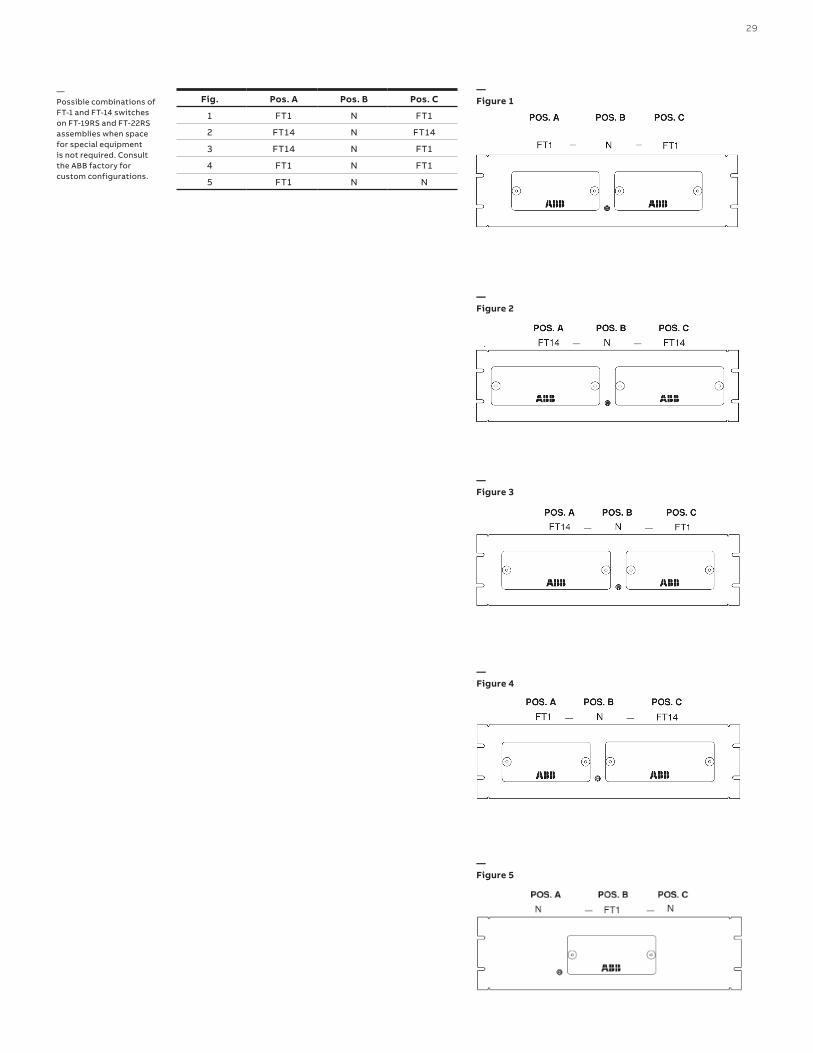
Fig. Pos. A Pos. B Pos. C
1 FT1 N FT1
2 FT14 N FT14
3 FT14 N FT1
4 FT1 N FT1
5 FT1 N N
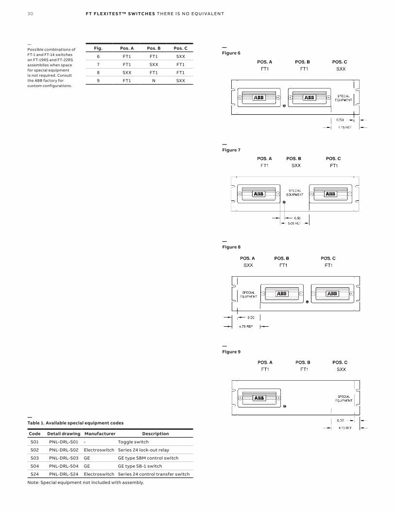
—Possible combinations of FT-1 and FT-14 switches on FT-19RS and FT-22RS assemblies when space for special equipment is not required. Consult the ABB factory for custom configurations.
—Figure 2
—Figure 3
—Figure 4
—Figure 5
—Figure 1
30 F T F LE X ITE S T ™ S W ITCH E S TH ER E I S N O EQ U I VA LENT
Fig. Pos. A Pos. B Pos. C
6 FT1 FT1 SXX
7 FT1 SXX FT1
8 SXX FT1 FT1
9 FT1 N SXX
Code Detail drawing Manufacturer Description
S01 PNL-DRL-S01 - Toggle switch
S02 PNL-DRL-S02 Electroswitch Series 24 lock-out relay
S03 PNL-DRL-S03 GE GE type SBM control switch
S04 PNL-DRL-S04 GE GE type SB-1 switch
S24 PNL-DRL-S24 Electroswitch Series 24 control transfer switch
—Table 1. Available special equipment codes
Note: Special equipment not included with assembly.
—Possible combinations of FT-1 and FT-14 switches on FT-19RS and FT-22RS assemblies when space for special equipment is not required. Consult the ABB factory for custom configurations.
—Figure 6
—Figure 7
—Figure 8
—Figure 9

31
Poles Potential Current A B C D E F G H I J Style number Code Options In-service test plug
10 10 0 P P P P P P P P P P 129A501G01 001 Black cover, screw terminals 129A062G10
10 10 0 T T T T T T T T T T 129A539G01 036 Black cover, screw terminals 129A062G10
10 10 0 P T T T T T T T T T 9688A17G01 584 Black cover, screw terminals 129A062G10
10 10 0 P P P P P P P P T T 1586C42G23 212 Black cover, screw terminals 129A062G10
10 10 0 P P P P T T T P P P 9676A14G01 452 Black cover, screw terminals 129A062G10
10 10 0 T T P P P P P P P P 1586C42G45 262 Black cover, screw terminals 129A062G10
10 4 6 P P P C - C C - C C - C P 129A514G01 014 Black cover, screw terminals 292B319G23
10 4 6 P C - C P C - C P C - C P 129A528G01 026 Black cover, screw terminals NONE
10 4 6 C - C C - C C - C P P P P 774B430G20 171 Black cover, screw terminals NONE
10 4 6 T T T T C - C C - C C - C 498A010G01 065 Black cover, screw terminals NONE
10 4 6 P P P P C - C C - C C - C 670B197G18 119 Black cover, screw terminals NONE
10 4 6 T T T C - C C - C C - C T 714B325G32 137 Black cover, screw terminals 292B319G23
10 4 6 C - C C - C C - C T T T T 774B430G24 183 Black cover, screw terminals NONE
10 3 7 P P C C - C C - C C - C P 129A535G01 033 Black cover, screw terminals 292B319G22
10 2 8 P C - C C - C C - C C - C P 129A518G01 018 Black cover, screw terminals 292B319G22
10 2 8 C - C C - C C - C C - C P P 837A407G01 083 Black cover, screw terminals NONE
10 2 8 C - C C - C C - C C - C T T 774B430G22 173 Black cover, screw terminals NONE
10 0 10 C - C C - C C - C C - C C - C 498A020G01 073 Black cover, screw terminals NONE
8 0 8 , C - C C - C C - C C - C , 129A517G01 017 Black cover, screw terminals 292B319G22
8 0 8 X R - R R - R R - R R - R X 9660A84G01 266 Black cover, screw terminals 292B319G22
6 0 6 , , , C - C C - C C - C , 129A516G01 016 Black cover, screw terminals 292B319G23
—Table 1 - FT -1 switch selection guide
— Most popular FT switches
Poles Potential Current A B C D E F G H I J K L M N Style number Code Options
14 14 0 P P P P P P P P P P P P P P FT4A14T14CN4001 4001 Clear cover, screw terminals
14 14 0 T T T T T T T T T T T T T T FT4A14T14CN4018 4018 Clear cover, screw terminals
14 6 8 P P P P P P C - C C - C C - C C - C FT4A14T06CN4046 4046 Clear cover, screw terminals
14 6 8 P P P C - C C - C C - C C - C P P P FT4A14T06CN4044 4044 Clear cover, screw terminals
14 6 8 C - C C - C C - C C - C P P P P P P FT4A14T06CN4068 4068 Clear cover, screw terminals
14 6 8 C - C C - C C - C C - C P P P P T T FT4A14T06CN4035 4035 Clear cover, screw terminals
14 6 8 T T T T C - C C - C C - C C - C T T FT4A14T06CN4052 4052 Clear cover, screw terminals
14 4 10 P P P P C - C C - C C - C C - C C - C FT4A14S04BN4151 4151 Black cover, stud terminals
14 2 12 C - C C - C C - C P P C - C C - C C - C FT4A14S02BN4177 4177 Black cover, stud terminals
14 0 14 C - C C - C C - C C - C C - C C - C C - C FT4A14T00CN4063 4063 Clear cover, screw terminals
12 4 8 T P Z W , R - R C - C 7 - 7 , 8 - 8 FT4A12T04CN4163 4163 Clear cover, screw terminals
11 3 8 P P P , C - C C - C C - C , C - C , FT4A11S03BN4127 4127 Black cover, stud terminals
—Table 2 - FT -14 switch selection guide
The above are the most popular FT configurations. For more styles please visit spine.abb.com/ftswitch

32 F T F LE X ITE S T ™ S W ITCH E S TH ER E I S N O EQ U I VA LENT
Style number Position A Position B Position C Options
FR3G001001001 001 001 001 3RU (centered), steel, ANSI 61 gray, screw terminals
FR3G171001001 171 001 001 3RU (centered), steel, ANSI 61 gray, screw terminals
FR2G001001001 001 001 001 2RU, steel, ANSI 61 gray, screw terminals
FR3H014001001 014 001 001 3RU (centered), steel, ANSI 70 gray, screw terminals
FR3H001001001 001 001 001 3RU (centered), steel, ANSI 70 gray, screw terminals
FR3G073001001 073 001 001 3RU (centered), steel, ANSI 61 gray, screw terminals
FRXG001001001 001 001 001 3RU (low), steel, ANSI 61 gray, screw terminals
FR3G014001001 014 001 001 3RU (centered), steel, ANSI 61 gray, screw terminals
FR3G001001262 001 001 262 3RU (centered), steel, ANSI 61 gray, screw terminals
FR3G183001262 183 001 262 3RU (centered), steel, ANSI 61 gray, screw terminals
FR4G001001001 001 001 001 4RU, steel, ANSI 61 gray, screw terminals
FR3G073212036 073 212 036 3RU (centered), steel, ANSI 61 gray, screw terminals
FR3G183001001 183 001 001 3RU (centered), steel, ANSI 61 gray, screw terminals
FR4G171001001 171 001 001 4RU, steel, ANSI 61 gray, screw terminals
FR3G083001001 083 001 001 3RU (centered), steel, ANSI 61 gray, screw terminals
FR3G083452000 083 452 000 3RU (centered), steel, ANSI 61 gray, screw terminals
FR2G014001001 014 001 001 2RU, steel, ANSI 61 gray, screw terminals
FR3G036036036 036 036 036 3RU (centered), steel, ANSI 61 gray, screw terminals
FR2G026001001 026 001 001 2RU, steel, ANSI 61 gray, screw terminals
FR3G026001026 026 001 026 3RU (centered), steel, ANSI 61 gray, screw terminals
FR3G171171001 171 171 001 3RU (centered), steel, ANSI 61 gray, screw terminals
FR2G001001000 001 001 000 2RU, steel, ANSI 61 gray, screw terminals
FR2G001000000 001 000 000 2RU, steel, ANSI 61 gray, screw terminals
FR3H014014014 014 014 014 3RU (centered), steel, ANSI 70 gray, screw terminals
FR3G026001001 026 001 001 3RU (centered), steel, ANSI 61 gray, screw terminals
—Table 3 - FT -19R switch assemblies
Style number Position A Position B Position C Options
SR2J183-N-183B 183 N 183 19 Inch mounting panel, screw terminals, 2RU, RAL7035 gray, steel
SR2J4037-N-4001CF 4037 N 4001 19 Inch mounting panel, screw terminals, 2RU, RAL7035 gray, steel
SR2JN-001-1NB N 001 N 19 Inch mounting panel, screw terminals, 2RU, RAL7035 gray, steel
SR3A014-N-001CF 014 N 00119 Inch mounting panel, screw terminals, 3RU (centered), brushed finish aluminum, individual clear covers, flat panel
SR3A036-S02-000C 036 S02 00019 Inch mounting panel, screw terminals, 3RU (centered), brushed finish aluminum, individual clear covers, special equipment
SR3G001-N-000C 001 N 00019 Inch mounting panel, screw terminals, 3RU (centered), ANSI 61 gray, individual clear covers
SR2JN-001-NB N 001 N19 Inch mounting panel, screw terminals, 2RU, RAL7035 gray, steel, standard individual black covers
SR2K014-N-001B 014 N 00119 Inch mounting panel, screw terminals, 2RU, black smooth surface, steel, standard individual black covers
SR3G001-N-001B 001 N 00119 Inch mounting panel, screw terminals, 2RU, ANSI 61 smooth surface, steel, standard individual black covers
—Table 3 - FT -19RS switch assemblies
The above are the most popular FT configurations. For more styles please visit spine.abb.com/ftswitch

33
—7. Test plug and accessories - ordering information
Test plugs Description Style number
In-service series test plug (order to match Flexitest FT-1 switch arrangement or FT relay case)
Reference spine.abb.com/ftswitch data sheet
Standard individual current circuit test plug - leads not included 7B4618G04
Standard individual current circuit test plug - 6’ length leads with retractable banana jacks, 13 AWG
7B4618G05
SafePlug - Individual current circuit test plug with open CT protection - leads not included
1VAC391001P001
SafePlug - Individual current circuit test plug with open CT protection - 6’ length leads with retractable banana jacks, 13 AWG Rated 600V, CatII, 20 A
1VAC391001P002
Standard separate source test plug (10 position)* Recommended for Electromechanical relay testing
1164046
Ergonomic separate source test plug (10 position) * Recommended for Flexitest FT-1 switches
1509B01G01
Separate source test plug (14 position) 1508B86G01
—7. Test plug and accessories - ordering information

34 F T F LE X ITE S T ™ S W ITCH E S TH ER E I S N O EQ U I VA LENT
FT test kit (Includes ABB bag) Items in test kit 9688A68G26 Rated voltage Rated current
1 red 6’ safety patch cord with retractable sleeve banana plug on both ends
600 VDC 32A
1 black 6’ safety patch cord with retractable sleeve banana plug on both ends
600 VDC 32A
1 red 10’ UTP cable with RJ-45 male connector on both ends 600V 30A
1 red safety plug-on test probe 1000V 10A
1 black safety plug-on test probe 1000V 10A
1 red safety plug-on alligator test clip 1000V 10A
1 black safety plug-on alligator test clip 1000V 10A
FT-1 ergonomic separate source test plug - 1509B01G01 600V 30A
FT individual current circuit test plug with open CT protection - 1VAC391001P001
600V 20A
Covers FT-1 FT-14 FT-19R
Standard individual shallow cover w/ thumb nuts - BLACK
128A973G01 128A973G05 9683A78G06
Standard individual shallow cover w/ thumb nuts - CLEAR
9669A64G01 9669A64G03 9683A78G07
Standard individual deep cover w/ thumb nuts - CLEAR 9676A32G01 9676A32G02 9683A78G01
Full length shallow cover w/ thumb nuts - BLACK Not applicable Not applicable 9676A28G06
Full length deep cover w/ thumb nuts - CLEAR Not applicable Not applicable 9676A28G01
Lockable shallow cover w/ thumb nuts & bracket- BLACK 9669A49G01 9669A49G07 Not applicable
Lockable shallow cover w/ thumb nuts & bracket- CLEAR 9669A49G05 9669A49G06 Not applicable
Lockable deep cover w/ thumb nuts & bracket - CLEAR 9669A49G02 9669A49G04 Not applicable
Full length shallow cover w/ thumb nuts - CLEAR Not applicable Not applicable 9676A28G09
Lockable full length shallow cover w/ thumb nuts & bracket - CLEAR
Not applicable Not applicable 9669A52G04
Lockable full length shallow cover w/ thumb nuts & bracket - BLACK
Not applicable Not applicable 9669A52G03
Lockable full length deep cover w/ thumb nuts & bracket - CLEAR
Not applicable Not applicable 9669A52G01
FT test kit (Includes ABB bag) Items in test kit 9688A68G25 Rated voltage Rated current
1 red 6’ safety patch cord with retractable sleeve banana plug on both ends
600 VDC 32A
1 black 6’ safety patch cord with retractable sleeve banana plug on both ends
600 VDC 32A
1 red 10’ UTP cable with RJ-45 male connector on both ends 600V 30A
1 red safety plug-on test probe 1000V 10A
1 black safety plug-on test probe 1000V 10A
1 red safety plug-on alligator test clip 1000V 10A
1 black safety plug-on alligator test clip 1000V 10A
FT-1 ergonomic separate source test plug - 1509B01G01 600V 30A
FT individual series test plug - 7B4618G04 600V 30A

35
Interlocking bars FT-1 FT-14
2 positions 1270547 9669A19G02
3 positions 1164048 9669A19G03
4 positions 02C9834G03 9669A19G04
5 positions 02C9834G04 9669A19G05
6 positions 02C9834G06 9669A19G06
7 positions Not Applicable 9669A19G07
8 positions 02C9834G07 9669A19G08
10 positions 02C9834G05 9669A19G10
14 positions Not applicable 9669A19G14
Miscellaneous Style number
FT-1 & FT-14 nut driver for stud & nut terminals 877A821G02
Unistrut adapter plate for railmount of FT-1F 9666A15H01
Label holder Sleeve (gloss polycarbonate) for FT-1 SW *To create and print custom labels, please use the template in the downloads section at this link.
1506B81H01
Banana thumbnut knobs for FT-14 separate source and FT-1 in-service series test plugs. Test plug knobs replace all older design knobs. The knobs have a 10-32 threaded brass insert that accommodates all types of test set leads and lugs
9683A91G02
36 F T F LE X ITE S T ™ S W ITCH E S TH ER E I S N O EQ U I VA LENT
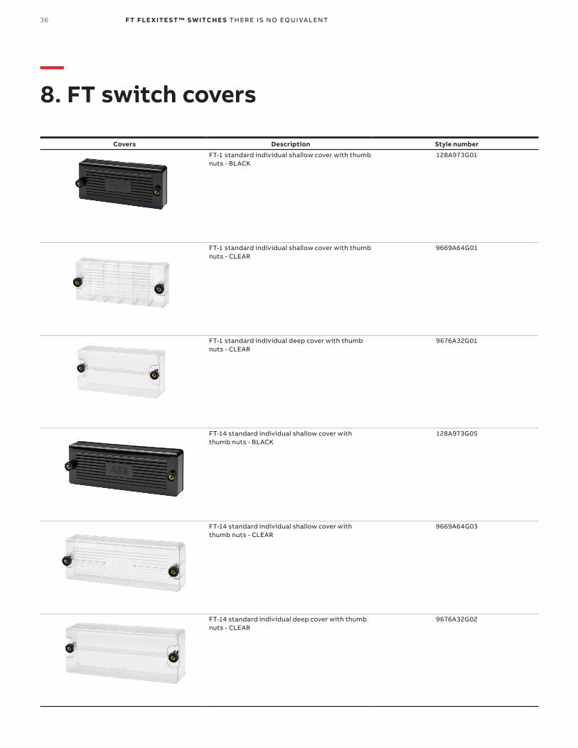
Covers Description Style number
FT-1 standard individual shallow cover with thumb nuts - BLACK
128A973G01
FT-1 standard individual shallow cover with thumb nuts - CLEAR
9669A64G01
FT-1 standard individual deep cover with thumb nuts - CLEAR
9676A32G01
FT-14 standard individual shallow cover with thumb nuts - BLACK
128A973G05
FT-14 standard individual shallow cover with thumb nuts - CLEAR
9669A64G03
FT-14 standard individual deep cover with thumb nuts - CLEAR
9676A32G02
—8. FT switch covers

37
Covers Description Style number
FT-19R individual standard individual shallow cover with thumb nuts and cover studs - BLACK
9683A78G06
FT-19R individual standard individual shallow cover with thumb nuts and cover studs - CLEAR
9683A78G07
FT-19R individual standard individual deep cover with thumb nuts and cover studs - CLEAR
9683A78G01
FT-19R full length shallow cover with thumb nuts - BLACK
9676A28G06
FT-19R full length shallow cover with thumb nuts - CLEAR
9676A28G09
FT-19R full length deep cover with thumb nuts - CLEAR
9676A28G01
38 F T F LE X ITE S T ™ S W ITCH E S TH ER E I S N O EQ U I VA LENT
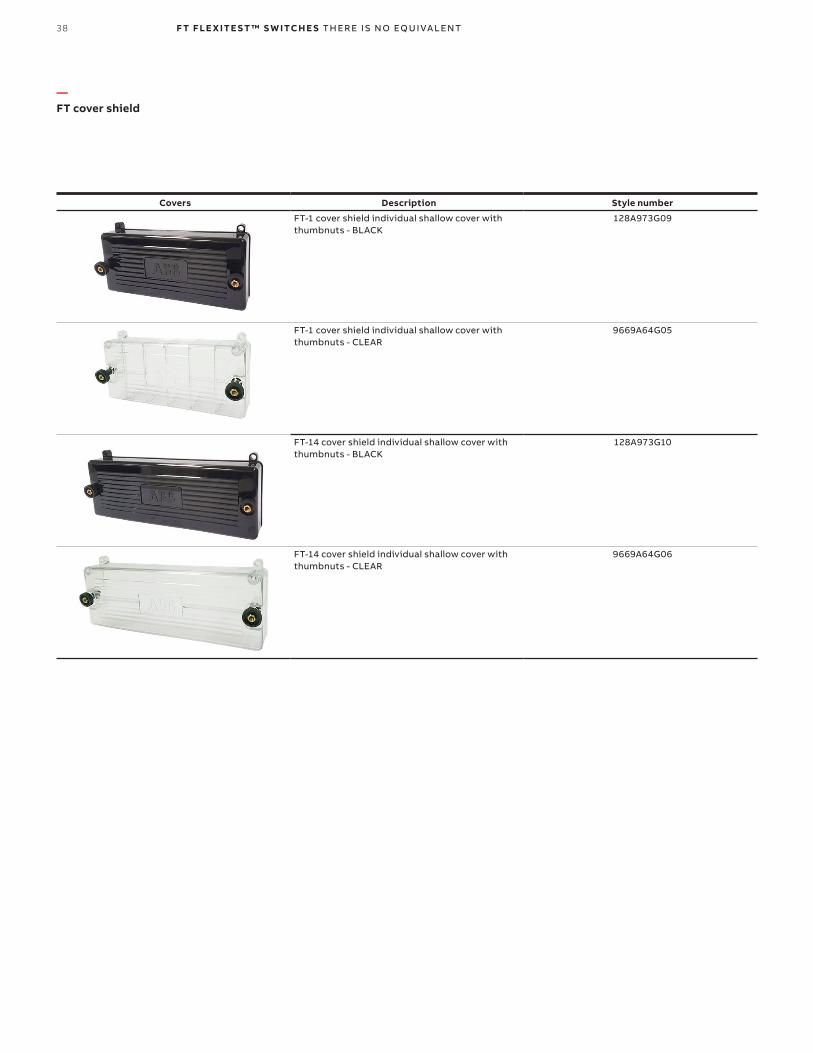
Covers Description Style number
FT-1 cover shield individual shallow cover with thumbnuts - BLACK
128A973G09
FT-1 cover shield individual shallow cover with thumbnuts - CLEAR
9669A64G05
FT-14 cover shield individual shallow cover with thumbnuts - BLACK
128A973G10
FT-14 cover shield individual shallow cover with thumbnuts - CLEAR
9669A64G06
— FT cover shield
39
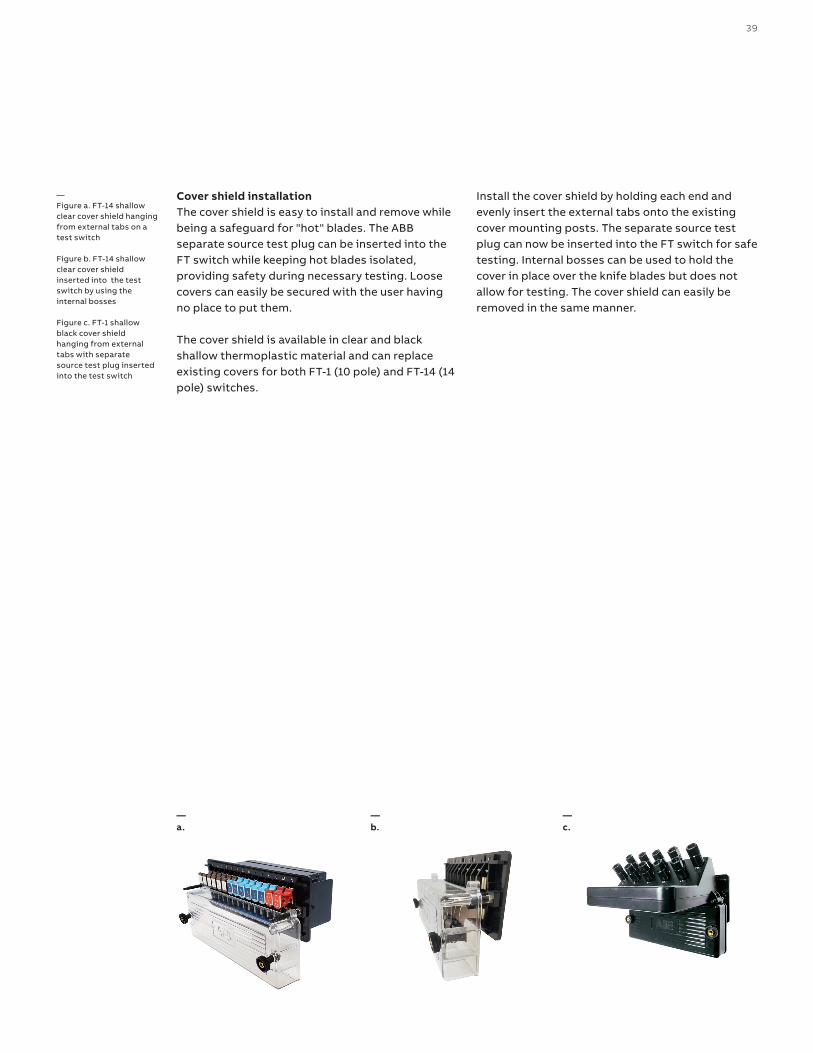
Cover shield installation The cover shield is easy to install and remove while being a safeguard for "hot" blades. The ABB separate source test plug can be inserted into the FT switch while keeping hot blades isolated, providing safety during necessary testing. Loose covers can easily be secured with the user having no place to put them.
The cover shield is available in clear and black shallow thermoplastic material and can replace existing covers for both FT-1 (10 pole) and FT-14 (14 pole) switches.
Install the cover shield by holding each end and evenly insert the external tabs onto the existing cover mounting posts. The separate source test plug can now be inserted into the FT switch for safe testing. Internal bosses can be used to hold the cover in place over the knife blades but does not allow for testing. The cover shield can easily be removed in the same manner.
—Figure a. FT-14 shallowclear cover shield hangingfrom external tabs on atest switch
Figure b. FT-14 shallowclear cover shield inserted into the test switch by using the internal bosses
Figure c. FT-1 shallow black cover shieldhanging from externaltabs with separatesource test plug insertedinto the test switch
—a.
—b.
—c.

40 F T F LE X ITE S T ™ S W ITCH E S TH ER E I S N O EQ U I VA LENT
All ABB Flexitest switches and assemblies are backed by a 12-year warranty. The quality of ABB products comes from years of experience and rigorous quality testing programs.
—9. Warranty

41
—Figure 08. FT-1 and FT-1X switch outline and drilling plan
—08 Outline
6.375 (161.9)
Fig.1 FT-1 with black cover and clear shallow cover
Fig.2 FT-1 with clear deep cover. Otherwise same as figure 1.
2.813 (71.4)
1.000 (25.4)
0.594 (15.1)
Panel
1.313 (33.3)
2.000 (50.8)
3.890 (98.8)
Panel
1.771 (45.0)
Drilling plan
1.406 (35.7)
3.125 (79.4)
2.844 (72.2)
2.844 (72.2)
2.688 (68.3)
2.688 (68.3)
1.156 (29.4)
1.156 (29.4)
0.125R (3.175)
Cutout
Panel
8.00 (203) = X08 10.00 (264) = X10
Dimensions inches (mm)
Otherwise same as figure 1.
FT-1X

42 F T F LE X ITE S T ™ S W ITCH E S TH ER E I S N O EQ U I VA LENT
—Figure 09. FT-1F switch outline and drilling plan
—09
Fig.1 FT-1F with clear deep cover
6.37 (161.91)
3.2 (81.38)
3.08 (78.36)6.06 (153.89)
0.52 (13.11) 0.31 (7.84)
2.64 (67.14)
Panel
5.75 (146.05)
3.3
(83.
82)
10-32 clearance or
10-32 tap
4.0
0 (
101.
53)
0.3
5 (8
.95)
3.6
5 (9
2.75
)
Terminal cover removed to show detail
Outline
Drilling plan
Dimensions inches (mm)
Fig.2 FT-1F with black and clear shallow cover
43
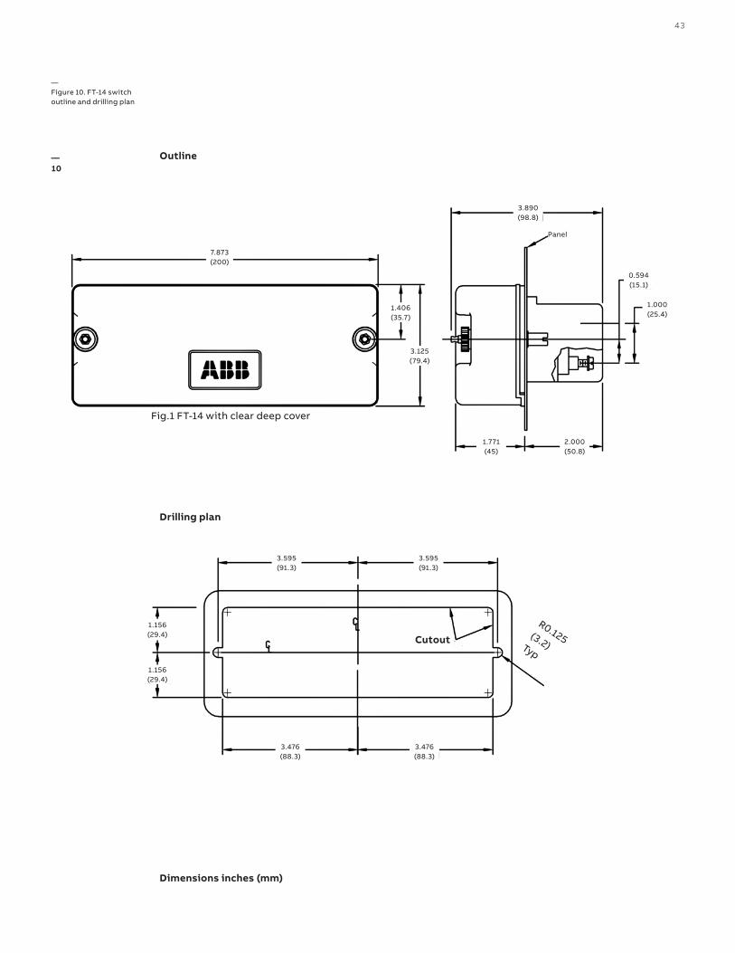
—Figure 10. FT-14 switch outline and drilling plan
—10
Dimensions inches (mm)
Outline
Drilling plan
7.873 (200)
1.406 (35.7)
3.125 (79.4)
0.594 (15.1)
1.000 (25.4)
2.000 (50.8)
1.771 (45)
3.890 (98.8)
Panel
Fig.1 FT-14 with clear deep cover
Cutout
3.595 (91.3)
3.595 (91.3)
1.156 (29.4)
3.476 (88.3)
3.476 (88.3)
1.156 (29.4)
R0.125 (3.2) Typ
44 F T F LE X ITE S T ™ S W ITCH E S TH ER E I S N O EQ U I VA LENT
3.89098.8
1.31533.4
2.00050.8
0.59415.1
1.00025.4
7.873200.0
1.40635.7
2.81371.4
6.667169.3
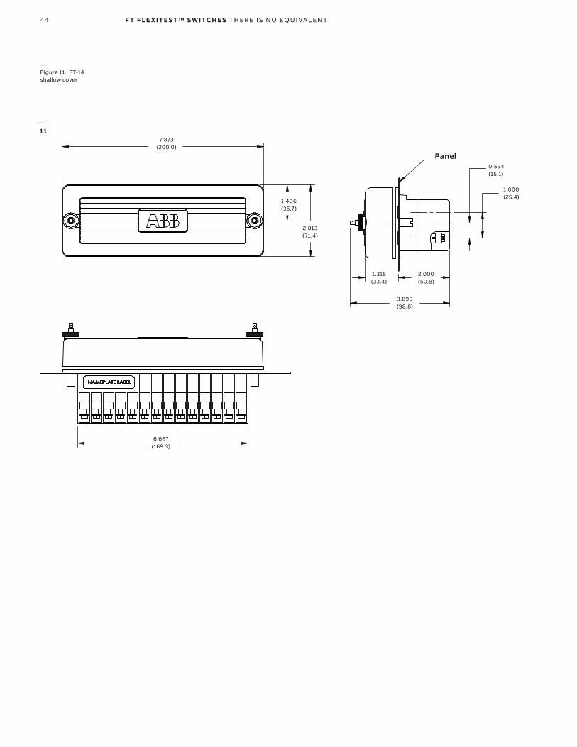
—Figure 11. FT-14 shallow cover
—11
7.873 (200.0)
1.406 (35.7)
2.813 (71.4)
0.594 (15.1)
1.000 (25.4)
2.000 (50.8)
1.315 (33.4)
3.890 (98.8)
Panel
6.667 (169.3)

45
3.46988
3.00076
19.000482.6
.875 [22]
18.186 [462]
1.73544.1
.580 [15]
2.00050.8
1.32033.5
3.32084.3
.86722.0
.82921.1
5.202132
1.28032.5
1OF2
—Figure 12. FT-19R
—12
19.000 (482.6)
3.000 (76)3.469
(88)
18.186 (462)
1.320 (33.5)
3.320 (84.3)
2.000 (50.8)
1.735 (44.1)
0.580 (15)0.875(22)
0.867 (22.0)
0.829 (21.1)
5.202 (132)
1.280 (32.5)

46 F T F LE X ITE S T ™ S W ITCH E S TH ER E I S N O EQ U I VA LENT
1.78545.3
2.00050.8
—Figure 13. FT-19R (continued)
—13
1.785 (45.3)
2.000 (50.8)

47
—Figure 14. FT-19R dimensions and layout for rack mounting
—14
0.234 (6)
19.000 (483)
18.186 (462)0.407(10)
3.469(88)
3.000(76)
0.875(22)
FT19R - 2RU
FT19R - 3RU
0.580(15)
4.250(108)
1.750 (44)
2.000 (51)
5.219(133)
1.484(38)
2.250(57)
(Otherwise same as 2RU)
FT19R - 3RU (Low switches)
4.750(121)
5.219 (133)
3.484 (89)
0.234(6)
1.764(45) Ref - Available area for user labels
FT19R - 4RU
(Otherwise same as 2RU)
Rotate this figure for 3RU with high switches
Ref - Available area for user labels2.514(64)1.484(38)
4.000(102)
6.969(177)
4.234(108)
Rotate this figure for 4RU with high switches
(Otherwise same as 2RU)
Dimensions inches (mm)

48 F T F LE X ITE S T ™ S W ITCH E S TH ER E I S N O EQ U I VA LENT
—Figure 15. Outline and drilling plan for FT-19R with flat panels (no rolled edges), rack or flush mounting for panels or cabinets
—15
18.468 (469.09)
17.500 (444.50)0.484 (12.29)
3.000 (76.20)2.750 (69.85)
0.250 (6.35) Dia 4 places
0.234 (5.94)
3.469 (88.11)
3.000 (76.20)
0.250 (6.35) Dia 4 places
18.468 (469.09)
17.500 (444.50)
18.468 (469.09)
17.500 (444.50)
18.468 (469.09)
17.500 (444.50)
0.250 (6.35) Dia 4 places
0.250 (6.35) Dia 4 places
Cutout
Cutout
Cutout
Cutout
2RU FT-19R
3RU FT-19R
3RU Off - Center FT-19R
4RU FT-19R
Ref.: Dimensions inches (mm) All figures show front view FT19R panels and cutouts
0.484 (12.29)
2.750 (69.85)2.250 (57.15)
0.375 (9.52)
1.484 (37.69)
5.219 (132.56)
2.250 (57.15)
4.750 (120.65)5.219 (132.56)
0.234 (5.94)0.484 (12.29)
4.750 (120.65)
2.750 (69.85)
0.484 (12.29)
2.750 (69.85)4.000 (101.60)
0.250 (6.35)
1.484 (37.69)
4.000 (101.60)6.968 (176.99)

49
19.000483
3.36085
3.000
76
7.873200.0
6.375161.9
1.06327.0
1.15529.3
.58015
2.00051
1.23331
.59415
1.00025
.87522
1.66442
3.11879.2
FT19RS
1OF1
—Figure 16. FT-19RS
—16
Dimensions inches (mm)
1.063 (27.0)
3.360 (85) 3.000
(76)
7.873 (200.0)
6.375 (161.9)
19.000 (483)
1.155 (29.3)
1.233 (31)
2.000 (51)
1.000 (25)
0.594 (15)
0.580 (15)
0.875 (22) 3.118
(79.2)1.664 (42)
50 F T F LE X ITE S T ™ S W ITCH E S TH ER E I S N O EQ U I VA LENT
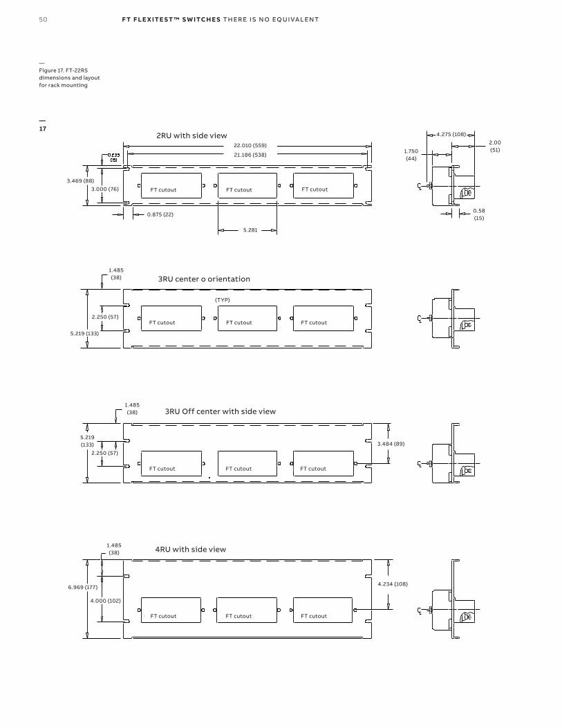
—Figure 17. FT-22RS dimensions and layout for rack mounting
—17
2RU with side view22.010 (559)
21.186 (538)
FT cutout FT cutout
3.469 (88)3.000 (76)
0.875 (22)
5.281
4.275 (108)
1.750 (44)
2.00 (51)
0.58 (15)
FT cutout FT cutout FT cutout
FT cutout FT cutout FT cutout
FT cutout FT cutout FT cutout
3RU center o orientation
3RU Off center with side view
4RU with side view
1.485 (38)
2.250 (57)
5.219 (133)
5.219 (133)
2.250 (57)
3.484 (89)
1.485 (38)
1.485 (38)
4.000 (102)
6.969 (177) 4.234 (108)
(TYP)
FT cutout

51
—Figure 18. Outline and drilling plan for FT-22RS with flat panels (no rolled edges), rack or flush mounting for panels or cabinets
—18
0.484 (12.294)
3.000 (76.200)2.750 (69.850)
21.468 (545.29)
20.500 (520.07)
Cutout
Cutout
Cutout
Cutout
21.468 (545.29)
20.500 (520.07)
21.468 (545.29)
20.500 (520.07)
21.468 (545.29)
20.500 (520.07)
0.250 (6.35) Dia 4 places
0.234 (5.944)
0.250 (6.35) Dia 4 places
0.250 (6.35) Dia 4 places
0.250 (6.35) Dia 4 places
0.234 (5.944)
2RU FT-22RS
3RU FT-22RS
3RU Off-center FT-22RS
4RU FT-22RS
3.469 (88.113)
3.000 (76.200)
1.484 (37.69)
5.219 (132.563)
2.250 (57.150)
0.484 (12.294)
2.750 (69.850)
2.750 (69.850)
5.219 (132.563)4.750 (120.650)4.750 (120.650)
0.484 (12.294)
0.484 (12.294)
2.750 (69.850)4.000 (101.60)
0.250 (6.350)
2.250 (57.150)
0.375 (9.52)
6.968 (176.987)
1.484 (37.69)
4.000 (101.60)

52 F T F LE X ITE S T ™ S W ITCH E S TH ER E I S N O EQ U I VA LENT
—Figure 19. Typical FT-1 switch connection schematic
—19
A B CFT-1*
A B C
* = FT-1 switch style No.129A514G01
FT-1 style No.129A514G01 (switch layout)
Terminal No.s (rear of Sw)
Internal schematic
Switch arrangement
Pole positions (front of Sw)
53
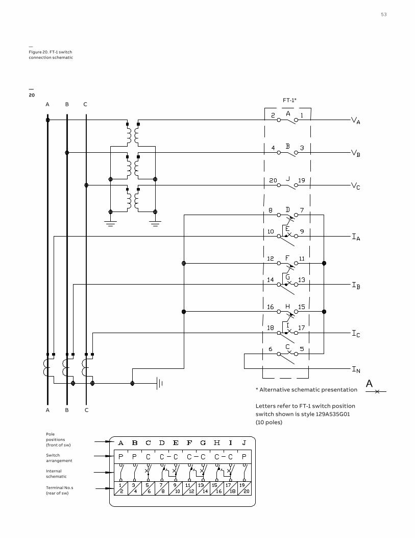
—Figure 20. FT-1 switch connection schematic
—20
Terminal No.s (rear of sw)
Internal schematic
Switch arrangement
Pole positions (front of sw)
* Alternative schematic presentation Letters refer to FT-1 switch position switch shown is style 129A535G01 (10 poles)
A B C
A B CFT-1*
54 F T F LE X ITE S T ™ S W ITCH E S TH ER E I S N O EQ U I VA LENT
PCB Mod
ule
PCB Mod
ule
A
B
G
H
L
M
N
VA(a)
VA(n)
IA(s1)
IA(s2)
VA
IA
VB
IB
VC
IC
VA(a)
VA(n)
IA(s2)
25
27
26
28
Phase ASensor
Phase ARelay
Combi Sensor
General Concept FT digital switch with Combi Sensors and REF615 Sensor Relay
A B C
Combi Sensor
Combi Sensor
IA(s1)
C
D
I
J
VB(a)
VB(n)
IB(s1)
IB(s2)
VB(a)
VB(n)
IB(s2)
Phase BSensor
Phase BRelay
IB(s1)
E
F
K
L
VC(a)
VC(n)
IC(s1)
IC(s2)
VC(a)
VC(n)
IC(s2)
Phase CSensor
Phase CRelay
IC(s1)
FT14 Digital
REF615 Relay For Sensor Application
X1
X2
P1
P2
P1
P2
P1
P2
PCB Mod
ule
PCB Mod
ule
A
B
G
H
L
M
N
VA(a)
VA(n)
IA(s1)
IA(s2)
VA
IA
VB
IB
VC
IC
VA(a)
VA(n)
IA(s2)
25
27
26
28
Phase ASensor
Phase ARelay
Combi Sensor
General Concept FT digital switch with Combi Sensors and REF615 Sensor Relay
A B C
Combi Sensor
Combi Sensor
IA(s1)
C
D
I
J
VB(a)
VB(n)
IB(s1)
IB(s2)
VB(a)
VB(n)
IB(s2)
Phase BSensor
Phase BRelay
IB(s1)
E
F
K
L
VC(a)
VC(n)
IC(s1)
IC(s2)
VC(a)
VC(n)
IC(s2)
Phase CSensor
Phase CRelay
IC(s1)
FT14 Digital
REF615 Relay For Sensor Application
P1
P2
P1
P2
P1
P2
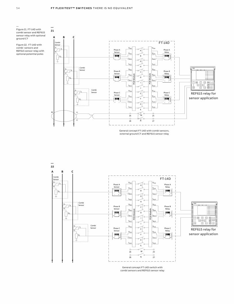
—Figure 21. FT-14D with combi sensor and REF615 sensor relay with optional ground CT Figure 22. FT-14D with combi sensors and REF615 sensor relay with optional potential poles
—22
—21
General concept FT-14D with combi sensors, external ground CT and REF615 sensor relay
General concept FT-14D switch with combi sensors and REF615 sensor relay
REF615 relay for sensor application
REF615 relay for sensor application
FT-14D
FT-14D
55
PCB Mod
ule
PCB Mod
ule
A
B
G
H
L
M
N
VA(a)
VA(n)
IA(s1)
IA(s2)
VA
IA
VB
IB
VC
IC
VA(a)
VA(n)
IA(s2)
25
27
26
28
Phase ASensor
Phase ARelay
Current Sensor
General Concept FT digital switch with Combi Sensors and REF615 Sensor Relay
A B C
IA(s1)
C
D
I
J
VB(a)
VB(n)
IB(s1)
IB(s2)
VB(a)
VB(n)
IB(s2)
Phase BSensor
Phase BRelay
IB(s1)
E
F
K
L
VC(a)
VC(n)
IC(s1)
IC(s2)
VC(a)
VC(n)
IC(s2)
Phase CSensor
Phase CRelay
IC(s1)
FT14 Digital
REF615 Relay For Sensor Application
X1
X2
P1
P2
P1
P2
P1
P2
RJ45 Adapter
Voltage Sensor
RJ45 Adapter
RJ45 Adapter
(1)
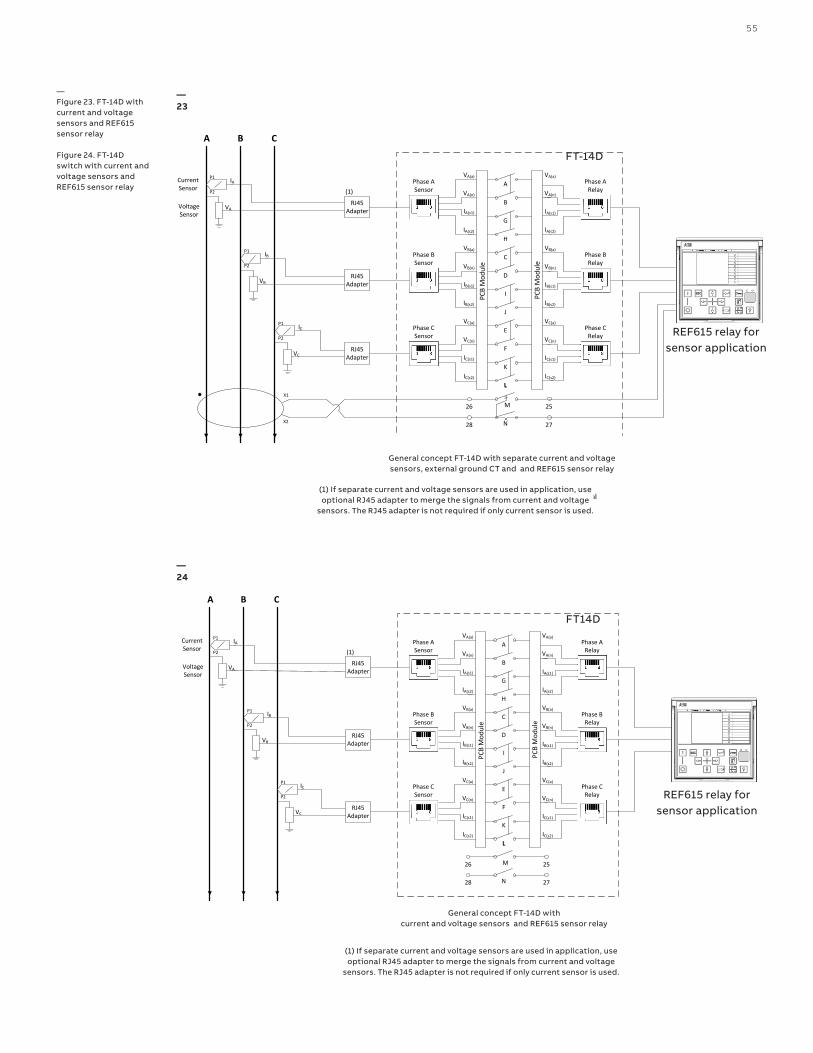
(1) – If separate current and voltage sensors are used in application, use optional RJ45 adapter to merge the signals from Current and Voltage Sensors. The RJ45 adapter is not required if only current sensor is used
PCB Mod
ule
PCB Mod
ule
A
B
G
H
L
M
N
VA(a)
VA(n)
IA(s1)
IA(s2)
VA
IA
VB
IB
VC
IC
VA(a)
VA(n)
IA(s2)
25
27
26
28
Phase ASensor
Phase ARelay
Current Sensor
General Concept FT digital switch with Combi Sensors and REF615 Sensor Relay
A B C
IA(s1)
C
D
I
J
VB(a)
VB(n)
IB(s1)
IB(s2)
VB(a)
VB(n)
IB(s2)
Phase BSensor
Phase BRelay
IB(s1)
E
F
K
L
VC(a)
VC(n)
IC(s1)
IC(s2)
VC(a)
VC(n)
IC(s2)
Phase CSensor
Phase CRelay
IC(s1)
FT14 Digital
REF615 Relay For Sensor Application
P1
P2
P1
P2
P1
P2
RJ45 Adapter
Voltage Sensor
RJ45 Adapter
RJ45 Adapter
(1)
(1) – If separate current and voltage sensors are used in application, use optional RJ45 adapter to merge the signals from Current and Voltage Sensors. The RJ45 adapter is not required if only current sensor is used
—Figure 23. FT-14D with current and voltage sensors and REF615 sensor relay Figure 24. FT-14D switch with current and voltage sensors and REF615 sensor relay
—23
—24
REF615 relay for sensor application
REF615 relay for sensor application
FT-14D
FT14D
General concept FT-14D with separate current and voltage sensors, external ground CT and and REF615 sensor relay
General concept FT-14D with current and voltage sensors and REF615 sensor relay
(1) If separate current and voltage sensors are used in application, use optional RJ45 adapter to merge the signals from current and voltage
sensors. The RJ45 adapter is not required if only current sensor is used.
(1) If separate current and voltage sensors are used in application, use optional RJ45 adapter to merge the signals from current and voltage
sensors. The RJ45 adapter is not required if only current sensor is used.

—ABB Distribution Solutions Digital Substation ProductsP.O. Box 699FI-65101 VAASA, FinlandPhone: +358 10 22 11
ABB Inc. 3022 NC 43 NorthPinetops, NC 27864Phone: +1 252 827 3212Customer support: + 1 800 929 7947 Ext 1
abb.com/mediumvoltageabb.com/relionabb.com/substationautomation1V
AC
394
64
1-P
G R
EV
H A
PR
IL 2
021
© Copyright 2021 ABB. All rights reserved. Specifications subject to change without notice.